JP5609366B2 - Winding method for hot-rolled steel sheet - Google Patents
Winding method for hot-rolled steel sheet Download PDFInfo
- Publication number
- JP5609366B2 JP5609366B2 JP2010164576A JP2010164576A JP5609366B2 JP 5609366 B2 JP5609366 B2 JP 5609366B2 JP 2010164576 A JP2010164576 A JP 2010164576A JP 2010164576 A JP2010164576 A JP 2010164576A JP 5609366 B2 JP5609366 B2 JP 5609366B2
- Authority
- JP
- Japan
- Prior art keywords
- coil
- winding
- hot
- rolled steel
- steel sheet
- Prior art date
- Legal status (The legal status is an assumption and is not a legal conclusion. Google has not performed a legal analysis and makes no representation as to the accuracy of the status listed.)
- Active
Links
- 238000004804 winding Methods 0.000 title claims description 86
- 229910000831 Steel Inorganic materials 0.000 title claims description 84
- 239000010959 steel Substances 0.000 title claims description 84
- 238000000034 method Methods 0.000 title claims description 14
- 238000001816 cooling Methods 0.000 claims description 51
- 239000000498 cooling water Substances 0.000 claims description 14
- 230000000717 retained effect Effects 0.000 claims description 3
- 230000014759 maintenance of location Effects 0.000 claims 1
- 230000002093 peripheral effect Effects 0.000 description 26
- 239000000463 material Substances 0.000 description 19
- 238000012546 transfer Methods 0.000 description 12
- XLYOFNOQVPJJNP-UHFFFAOYSA-N water Substances O XLYOFNOQVPJJNP-UHFFFAOYSA-N 0.000 description 12
- 238000004364 calculation method Methods 0.000 description 10
- 230000000694 effects Effects 0.000 description 10
- 238000005452 bending Methods 0.000 description 9
- 238000005096 rolling process Methods 0.000 description 9
- 239000008186 active pharmaceutical agent Substances 0.000 description 8
- 238000005098 hot rolling Methods 0.000 description 6
- 230000007423 decrease Effects 0.000 description 5
- 238000009826 distribution Methods 0.000 description 4
- 238000002474 experimental method Methods 0.000 description 4
- 238000002347 injection Methods 0.000 description 4
- 239000007924 injection Substances 0.000 description 4
- 238000004519 manufacturing process Methods 0.000 description 4
- 238000004458 analytical method Methods 0.000 description 3
- 230000008602 contraction Effects 0.000 description 3
- 230000007704 transition Effects 0.000 description 3
- XEEYBQQBJWHFJM-UHFFFAOYSA-N Iron Chemical compound [Fe] XEEYBQQBJWHFJM-UHFFFAOYSA-N 0.000 description 2
- 238000010586 diagram Methods 0.000 description 2
- 238000005516 engineering process Methods 0.000 description 2
- VNWKTOKETHGBQD-UHFFFAOYSA-N methane Chemical compound C VNWKTOKETHGBQD-UHFFFAOYSA-N 0.000 description 2
- 230000008569 process Effects 0.000 description 2
- 230000009467 reduction Effects 0.000 description 2
- 238000003466 welding Methods 0.000 description 2
- 230000001133 acceleration Effects 0.000 description 1
- 230000008859 change Effects 0.000 description 1
- 230000000052 comparative effect Effects 0.000 description 1
- 239000010779 crude oil Substances 0.000 description 1
- 230000003247 decreasing effect Effects 0.000 description 1
- 230000007547 defect Effects 0.000 description 1
- 230000006872 improvement Effects 0.000 description 1
- 238000011835 investigation Methods 0.000 description 1
- 229910052742 iron Inorganic materials 0.000 description 1
- 238000005259 measurement Methods 0.000 description 1
- 239000003345 natural gas Substances 0.000 description 1
- 230000003449 preventive effect Effects 0.000 description 1
- 238000012545 processing Methods 0.000 description 1
- 238000010791 quenching Methods 0.000 description 1
- 230000000171 quenching effect Effects 0.000 description 1
- 230000005855 radiation Effects 0.000 description 1
- 238000011084 recovery Methods 0.000 description 1
- 229920006395 saturated elastomer Polymers 0.000 description 1
- 239000002893 slag Substances 0.000 description 1
- 239000007921 spray Substances 0.000 description 1
- 238000005507 spraying Methods 0.000 description 1
- 239000002436 steel type Substances 0.000 description 1
- 239000002344 surface layer Substances 0.000 description 1
- 239000013077 target material Substances 0.000 description 1
- 238000012360 testing method Methods 0.000 description 1
Images


Landscapes
- Winding, Rewinding, Material Storage Devices (AREA)
Description
本発明は、熱延鋼板、特に高強度パイプの素材となる高強度厚肉熱延鋼板を安定的に製造するための巻き取り方法に関するものである。 The present invention, hot-rolled steel sheet, in which relates to a particularly high strength pipe material become high-strength hot rolled thick steel plate winding takes Way Method for producing stably a.
近年、主として大陸パイプラインでの原油や天然ガス等の資源の輸送効率化を目的に、API規格にしてX70〜X100といった大径厚肉高強度パイプ材の需要が高まっている。これらの資源を効率的に輸送するため、パイプ内部には高い内圧がかけられており、かつ寒冷地での使用や地震による地殻変動なども考慮し、高靭性、高強度といった特性がパイプ材にとって非常に重要となっている。これらのパイプラインにて使用されるパイプは肉厚が15〜25mm程度、外径は20インチ程度以上と大径であり、従来は高強度パイプとしては長手方向に縦長形状である厚鋼板の短辺側を円形に成形した後、突合せ部を長手方向にサブマージアーク溶接してパイプとするUOE鋼管が多用されている。通常、厚鋼板は熱間スラブを1基、あるいは2基の圧延機を有する厚板ミルでの多パス圧延にて略矩形形状に製造されるものであり、その製品長は最大でも30m程度である。 In recent years, demand for large-diameter, thick-walled, high-strength pipe materials such as X70 to X100 as API standards has been increasing mainly for the purpose of improving the transportation efficiency of resources such as crude oil and natural gas in continental pipelines. In order to efficiently transport these resources, high internal pressure is applied to the inside of the pipe, and characteristics such as high toughness and high strength are also considered for pipe materials in consideration of crustal deformation due to use in cold regions and earthquakes. It has become very important. The pipes used in these pipelines have a large diameter of about 15 to 25 mm and an outer diameter of about 20 inches or more. Conventionally, as a high-strength pipe, it is a short steel plate that is vertically long in the longitudinal direction. UOE steel pipes are often used in which the side is formed into a circular shape and then the butt portion is subjected to submerged arc welding in the longitudinal direction to form a pipe. Usually, a thick steel plate is manufactured in a substantially rectangular shape by multi-pass rolling in a thick plate mill having one or two hot slabs, and the product length is about 30 m at the maximum. is there.
これに対し、近年、厚鋼板を薄板圧延用の熱間圧延ラインにて圧延してコイル状に巻き取って熱延鋼帯コイルとした後、コイルを巻きほどいて電縫管に成形する他、熱延鋼板を長手方向にらせん状に成形すると同時に板幅端部の突合せ部を溶接しながらパイプに製造するスパイラル鋼管の需要が高まっている。熱延鋼板コイルは、最大45トン程度までの製造が可能であり、例えば20mm厚み、板幅1900mm程度であれば熱延鋼板の長さは151m程度となり、電縫管では成形したときのパイプ長は約151m、直径28インチのスパイラル鋼管に成形したときのパイプ長は約128mとなる。このように、パイプ成形前の母材を熱延鋼板コイルとすることにより、厚鋼板から製造する場合に比べ、連続して長いパイプの製造が可能となることから生産性の向上も期待できる。 On the other hand, in recent years, after rolling a thick steel plate in a hot rolling line for thin plate rolling and winding it into a coil shape to form a hot rolled steel strip coil, unwinding the coil and forming it into an electric resistance welded tube, There is an increasing demand for spiral steel pipes that are formed into a pipe while forming a hot-rolled steel sheet in a spiral shape in the longitudinal direction and simultaneously welding the butted portion at the end of the sheet width. The hot-rolled steel sheet coil can be manufactured up to about 45 tons. For example, if the thickness is 20 mm and the width is about 1900 mm, the length of the hot-rolled steel sheet is about 151 m. Is about 151 m and the pipe length when formed into a spiral steel pipe having a diameter of 28 inches is about 128 m. Thus, by using a hot-rolled steel sheet coil as the base material before forming the pipe, it is possible to manufacture a long pipe continuously as compared with the case of manufacturing from a thick steel sheet, and thus an improvement in productivity can be expected.
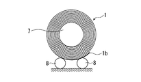
さて、高強度厚肉鋼板をコイル状に巻き取る場合、材料の剛性が高いが故に、巻き取り装置のピンチロールやラッパーロールの剛性不足、そしてマンドレルのトルク不足、その他先端部の巻き付き不良等、様々な課題が発生する。例えば、厚肉鋼板の最先端部はピンチロールやラッパーロール等によって曲げることが困難であり、最先端部の巻き付き不良を改善するため、巻き付き後3周程度まではマンドレル外径を拡大し、マンドレルと鋼板の密着性を高めてスリップを防止し巻き付きやすくする方法が提案されている(例えば、特許文献1)。 Now, when winding a high-strength thick steel sheet in a coil shape, the rigidity of the material is high, so the pinch roll or wrapper roll of the winding device is insufficient, the torque of the mandrel is insufficient, other winding defects at the tip, etc. Various issues arise. For example, it is difficult to bend the leading edge of a thick steel plate with a pinch roll or a wrapper roll, etc. In order to improve the winding failure of the leading edge, the mandrel outer diameter is increased up to about three laps after winding. A method has been proposed in which the adhesion between the steel sheet and the steel sheet is improved to prevent slipping and to facilitate winding (for example, Patent Document 1).
高強度厚肉熱延鋼板をコイル状に巻き取る場合、先端部は例えば特許文献1に開示されている技術等により対応が可能であるが、コイル外周側となるストリップ尾端部ではスプリングバックによる巻き緩みが発生しやすく、巻き緩みがひどい場合にはコイル台車に搭載した状態にてコイラーから抜き出す際にコイルが浮き上がって台車から転げ落ちるほどである。通常、熱延コイラーでのストリップの巻き取りでは、図3に示すように、最尾端部1bがコイル下側の位置にて停止するようにマンドレルの回転制御を行っており、コイルの自重にて尾端部のスプリングバック変形を抑圧している。しかしながら、近年のラインパイプ素材の高強度化・厚肉化のニーズは著しく、これらの材料を巻き取る際にはコイルの自重だけでは尾端部のスプリングバック変形を抑制できない状況となっている。このため、高強度材の圧延が可能である強圧下圧延機を具備した熱間圧延ラインにおいても、コイラーでの巻き取り可否が高強度厚肉熱延鋼板の製造可否を決定しているといっても過言ではない。なお、本発明では高強度の定義はAPI規格にてX65以上、厚肉熱延鋼板は製品厚にて19mm以上のものを対象としている。
When winding a high-strength thick-walled hot-rolled steel sheet in a coil shape, the tip portion can be handled by, for example, the technique disclosed in
図4は、従来の一般的な熱延鋼板の巻き取り装置を示している。
一般に、コイラーにて熱延鋼板1の先端部を巻き取るにあたっては、ピンチロール3、マンドレル7、ラッパーロール5a〜5dなどの各ロールの周速は、熱延鋼板1の厚さや硬さ(強度)などに応じて、熱延鋼板1の搬送速度に対し、10〜30%のリード率を持たせた値、すなわち、10〜30%速い速度に制御している。この際、マンドレル7、ラッパーロール5a〜5dのリード率は、ピンチロール3のリード率以上としている。そして、熱延鋼板1の先端部の巻き付き完了の時点でリード率はクリアされ、以降、熱延鋼板1の搬送速度と実質的(冷却による熱収縮や張力による幅縮みなどの影響を除けばという意味)に同期した周速に制御される。なお、図4ではラッパーロールの数は4個としているが、一般的に、熱延鋼板の巻き取り装置では3個のラッパーロールを具備しているものも多い。
FIG. 4 shows a conventional general hot-rolled steel sheet winding device.
Generally, when winding the front-end | tip part of the hot-rolled
コイラー内にて、熱延鋼板1の先端部に緩みが生じ、波打って巻き取られたような場合、以降の巻き取りが継続できなくなるか、運良く巻き取れても、以降の巻きが、波打って巻き取られた巻きの外方に重なることにより、巻きが太くなり、コイラーのハウジングからはみ出す大きさになってしまう結果、詰まって抜き出せなくなってしまい、ひとたびそのような事態になると、コイラーの各部が受ける損傷は大きく、復旧までに何時間もの多大な時間を要することとなる。
In the coiler, when the leading end of the hot-rolled
いずれにせよ、このような事態になるのを防止するため、コイラーにて熱延鋼板1の先端部を巻き取るにあたっては、熱延鋼板1の緩みを最小限にする目的で、熱延鋼板1の最先端部1aがマンドレル7に巻き付きを開始してから巻き付き完了までの間、ピンチロール3、マンドレル7、ラッパーロール5a〜5dの各ロールの周速にはリード率をもたせ、熱延鋼板1を引張りながら巻き取りを行うことで、熱延鋼板1の先端部に緩みが生じて波打って巻き取られるのを防止している。そして、熱延鋼板1の先端部の巻き付き完了後は、マンドレル7は、熱延鋼板1の搬送速度、すなわち、仕上圧延機の最終圧延機の出側における熱延鋼板1の搬送速度と実質的に同期しながら、ピンチロール3との間で、所望の張力に近づける張力制御を行いながら、尾端まで巻き取りを行っている。この際、先端の巻き付きが完了する5巻き程度以上では、ラッパーロール5a〜5dをコイルから退避させ、ピンチロール3とマンドレル7間の張力のみで緩み無く巻き取りを行っている。なお、熱延鋼板1の最尾端部がピンチロール3を抜けた後は、熱延鋼板1には張力が作用しないことから、一般的な熱延鋼板の巻き取り作業では、退避させておいたラッパーロール5a〜5dのうち少なくとも1つ以上のラッパーロールをコイル外周部に押圧し、コイル尾端部1bの緩みを抑制している。
In any case, in order to prevent such a situation from occurring, when winding the tip of the hot rolled
しかしながら、本発明で特に対象としているラインパイプ素材に代表される高強度厚肉材では、鋼板の断面積が大きく、かつ強度が非常に高いことから、タイトに巻き取るための張力を付与することが非常に困難となる。また、一般的に高強度材では曲げ加工後のスプリングバックが非常に大きく、コイル巻き取り完了後、クレードルロール8をコイル下方より上昇させてコイルに押圧した後、コイル抜き出しのためにラッパーロール5a〜5dを退避し、コイル回転中心となっていたマンドレルを縮径する際、マンドレル7やラッパーロール5a〜5dで固定されていた弾性歪成分が開放される、すなわちスプリングバックが発生し、コイル外周部の巻き緩みが顕著となる。図5に高強度厚肉材の巻き取り後、コイル抜き出し時での巻き姿の例を示すが、コイルの巻き緩みが大きい場合にはコイラーからの抜き出しができない、コイルカーでの搬送時のコイル振動が顕著となって姿勢が不安定となる、また、バンドがけ後、搬送時にバンドが切れるなどの問題点があった。
However, high-strength thick materials represented by the line pipe material particularly targeted in the present invention have a large cross-sectional area of the steel plate and very high strength, so that tension for winding up tightly is applied. Becomes very difficult. In general, a high-strength material has a very large spring back after bending, and after winding of the coil is completed, the
本発明は、上記のような事情に鑑みてなされたものであり、熱間圧延ラインにおける高強度厚肉熱延鋼板の巻き取り方法を提供することを目的とするものである。 The present invention has been made in view of the above circumstances, it is an object to provide a winding take Way Method of high-strength hot rolled thick steel plate in hot rolling lines.
前述したごとく、通常、熱延コイルの巻き取りでは熱延鋼板の最尾端部がコイル下側に位置するようにマンドレルの回転を停止した後、巻取り中はコイル下方にて待機しているコイル台車を上昇させてコイル尾端部に接触させ、コイルの自重で尾端部の巻き緩みを抑えこんだ状態としてからマンドレルやラッパーロールを開放し、そのままコイル台車に搭載した状態にてコイラーから抜き出している。そして、コイラーから抜き出された熱延コイルは、搬送中の巻き緩みを防止するために、コイラーに隣接して設置されているバンディング装置にて1本、あるいは複数本の帯状鋼帯で最外周部を環状に固定される。しかし、高強度厚肉熱延鋼板の巻き取りでは、外周部の巻き緩みにより、コイラーから抜き出してバンディング装置に移送するまでの間に不安定な状態になりやすく、何らかの対策技術の確立が必要であった。 As described above, normally, in winding a hot-rolled coil, after the mandrel is stopped so that the rearmost end of the hot-rolled steel sheet is located on the lower side of the coil, the coil is waiting under the coil during winding. The coil carriage is lifted and brought into contact with the tail end of the coil, and the mandrel and wrapper roll are released after the coil's own weight has suppressed the loosening of the tail end, and the coil carriage is mounted on the coil carriage as it is. I'm pulling out. The hot-rolled coil extracted from the coiler has one or more strip steel strips at the outermost periphery in a banding device installed adjacent to the coiler in order to prevent winding looseness during conveyance. The part is fixed in an annular shape. However, when winding a high-strength thick-walled hot-rolled steel sheet, due to the loosening of the outer periphery, it tends to become unstable before it is extracted from the coiler and transferred to the banding device, and some countermeasure technology needs to be established. there were.
本発明は、以上のような状況に鑑みなされたものであり、以下のとおりである。
(1)熱延鋼板の巻き取り装置にて高強度熱延鋼板をコイル状に巻き取る方法であって、熱延鋼板の先端部から尾端部までをコイル状に巻き取った後、コイルに対して遊星状に配置された複数のラッパーロールをコイルに押し付けた状態にてコイルに対して冷却水を噴射し、コイル外周部を所定の冷却時間だけ冷却した後、冷却を停止してコイルを所定の滞留時間だけ巻き取り装置内に滞留させた後にラッパーロールを解放し、巻き取り機から抜き出すことを特徴とする、熱延鋼板の巻き取り方法。
(2) 前記(1)において、コイル外周部の所定の冷却時間を5秒以上とすることを特徴とする、熱延鋼板の巻き取り方法。
(3) 前記(1)又は(2)において、冷却停止後のコイルの所定の滞留時間を20秒以上とすることを特徴とする、熱延鋼板の巻き取り方法。
The present invention has been made in view of the above situation, and is as follows.
(1) A method of winding a high-strength hot-rolled steel sheet in a coil shape with a hot-rolled steel sheet winder, after winding the hot-rolled steel sheet from the front end portion to the tail end portion in a coil shape, On the other hand, cooling water is sprayed onto the coil in a state where a plurality of wrapper rolls arranged in a planetary shape are pressed against the coil, and the coil outer periphery is cooled for a predetermined cooling time. A method for winding a hot-rolled steel sheet, wherein the wrapper roll is released after being held in the winding device for a predetermined staying time and extracted from the winding machine.
(2) The method for winding a hot-rolled steel sheet according to (1), wherein the predetermined cooling time of the outer periphery of the coil is 5 seconds or more.
(3) The method for winding a hot-rolled steel sheet according to (1) or (2) above, wherein the predetermined residence time of the coil after cooling is stopped is 20 seconds or longer .
本発明によれば、従来、スプリングバックによる巻き緩みが問題であった高強度厚肉熱延鋼板コイルを安定的に巻き取ることが可能となる。 According to the present invention, it is possible to stably wind up a high-strength thick-walled hot-rolled steel sheet coil, which has conventionally been a problem of loose winding due to springback.
以下、本発明の実施形態について説明する。
本発明者らは、前述の高強度熱延鋼板コイルのスプリングバックによるコイル巻き緩みを抑制するための技術について鋭意検討を重ねた結果、巻き取り直後の熱延鋼板の外周部を急激に冷却して熱収縮させ、コイル外周部に円周方向の伸び歪を発生させることによってスプリングバックを低減させる方法を着想した。一般に、曲げ加工では、曲げの外側では引張応力、曲げの内側では圧縮応力が作用し、加工力を除去、すなわち除荷過程において、板厚断面内の曲げモーメントが0になる位置まで弾性的に曲率が変化するスプリングバック変形が生ずる。コイル外周部から冷却した場合、コイル外周側ほど温度低下が大きく、かつ温度低下した熱延鋼板は温度低下量に応じて熱収縮をおこすが、温度低下の少ないコイル内部の熱収縮量は小さいことから、大きく熱収縮するコイル外周部では巻き形状が保持されるために収縮できずに伸び歪が発生することになる。例えば、巻き取り時の温度500℃、降伏応力σyが450MPa、ヤング率Eが160GPaの材料で、板厚25.4mm、コイル外径φ1600mmの高強度熱延鋼板コイルの場合、最外周での曲げ歪ε1は次の(1)式により約±0.016となる。
Hereinafter, embodiments of the present invention will be described.
As a result of intensive studies on the technology for suppressing coil loosening due to springback of the above-described high-strength hot-rolled steel sheet coil, the present inventors have rapidly cooled the outer periphery of the hot-rolled steel sheet immediately after winding. The idea was to reduce the springback by heat shrinking and generating circumferential strain in the outer periphery of the coil. Generally, in bending, tensile stress is applied outside the bend, and compressive stress is applied inside the bend to remove the processing force, that is, elastically up to a position where the bending moment in the plate thickness section becomes zero in the unloading process. Springback deformation with a changing curvature occurs. When cooling from the outer periphery of the coil, the temperature decrease is larger toward the outer periphery of the coil, and the hot-rolled steel sheet whose temperature has decreased causes thermal contraction according to the amount of temperature decrease, but the amount of thermal contraction inside the coil with little temperature decrease is small. Therefore, since the winding shape is maintained at the outer peripheral portion of the coil that is largely thermally contracted, it cannot be contracted, and elongation strain occurs. For example, in the case of a high-strength hot-rolled steel sheet coil having a thickness of 25.4 mm and a coil outer diameter of φ1600 mm made of a material having a winding temperature of 500 ° C., a yield stress σy of 450 MPa, a Young's modulus E of 160 GPa, bending at the outermost periphery The strain ε 1 is about ± 0.016 according to the following equation (1).

(1)式において、hは熱延鋼板の板厚、ρはコイル外周での曲率半径である。また、最外周の熱延鋼板の曲げの外表面側が引張歪、内表面側が圧縮歪であり、次の(2)式で計算される弾塑性境界歪ε0は約0.0028であり、板厚中心部近傍をのぞいて塑性状態となっている。 In equation (1), h is the thickness of the hot-rolled steel sheet, and ρ is the radius of curvature at the outer periphery of the coil. Further, the outer surface side of the outermost hot-rolled steel sheet is tensile strain and the inner surface side is compressive strain, and the elastic-plastic boundary strain ε 0 calculated by the following equation (2) is about 0.0028. It is in a plastic state except for the vicinity of the thickness center portion.
一般的に、鋼の熱膨張係数は1.2×10−5(/℃)程度であることから、例えば冷却により鋼板温度を100℃低下させることにより0.0012の熱収縮歪、また200℃低下させれば0.0024の熱収縮歪が発生する。これは、(2)式で計算された弾塑性境界歪ε0とほぼ同等であり、実際には熱収縮の小さい内部の抵抗にて収縮変形が拘束されるため、温度低下の大きい外周側の鋼板には大きな伸び歪が発生する。この際、ラッパーロール5a〜5dは所定の圧力にてコイルに押圧して冷却収縮によるコイルの動きを拘束し、かつコイル外周側を円周方向に均一に冷却するため、マンドレルを一定速度で回しておくことが望ましい。このような状態、すなわち複数のラッパーロールをコイルに押し付けた状態にてコイル外周部の曲げ状態を保持したまま、コイルに対して冷却水を噴射し、コイル外周部を所定の冷却時間だけ冷却してコイル最外周板の板厚方向に大きな温度分布を発生させた状態とした後に冷却を停止して巻き取り装置内にコイルを滞留させると、温度の高い内周側からの復熱により外周側表層の温度が急激に上昇し、数十秒後には外周側からの空冷・放射による冷却現象と内部からの復熱現象が平衡状態となり、その後はゆっくりと温度低下していく。この過程で、外周側は温度上昇により熱膨張するため、曲げ曲率が大きくなる方向、すなわち外周側の伸び率を緩和する方向に変形が生ずる。すなわち、もともと巻き取りによる曲げ変形にて生じていた外周側の引張応力−内周側の圧縮応力の分布に対し、外周側には圧縮応力、内周側には引張応力が重畳することとなり、巻き取りによる曲げによって生じた板厚方向の応力分布が大きく緩和することとなる。この状態から除荷する、すなわちコイルを巻き取り機から抜き取るためクレードルロール8を上昇させてコイルに押圧し、マンドレル7を縮径、ラッパーロール5a〜5dをコイルから離反させると、スプリングバックによるコイルの上下左右の変動を大きく低減できることを確認した。
In general, since the thermal expansion coefficient of steel is about 1.2 × 10 −5 (/ ° C.), for example, by reducing the steel plate temperature by 100 ° C. by cooling, a thermal shrinkage strain of 0.0012 or 200 ° C. If it is lowered, 0.0024 heat shrinkage strain is generated. This is almost the same as the elastoplastic boundary strain ε 0 calculated by the equation (2). In fact, the shrinkage deformation is constrained by the internal resistance with a small thermal shrinkage. A large elongation strain occurs in the steel sheet. At this time, the wrapper rolls 5a to 5d are pressed against the coil with a predetermined pressure to constrain the movement of the coil due to cooling contraction, and the coil outer periphery side is uniformly cooled in the circumferential direction so that the mandrel is rotated at a constant speed. It is desirable to keep it. In such a state, that is, in a state where a plurality of wrapper rolls are pressed against the coil, while cooling the outer periphery of the coil, the cooling water is sprayed onto the coil to cool the outer periphery of the coil for a predetermined cooling time. If the coil is retained in the winder after cooling is stopped after a large temperature distribution is generated in the thickness direction of the outermost coil of the coil, The temperature of the surface layer rises rapidly, and after several tens of seconds, the cooling phenomenon due to air cooling / radiation from the outer peripheral side and the recuperation phenomenon from the inside are in an equilibrium state, and then the temperature gradually decreases. In this process, the outer peripheral side thermally expands due to a temperature rise, so that deformation occurs in the direction in which the bending curvature increases, that is, in the direction in which the elongation on the outer peripheral side is relaxed. That is, with respect to the distribution of the tensile stress on the outer peripheral side-the compressive stress on the inner peripheral side that was originally caused by the bending deformation by winding, the compressive stress is superimposed on the outer peripheral side and the tensile stress is superimposed on the inner peripheral side, The stress distribution in the plate thickness direction caused by bending by winding is greatly relaxed. When unloading from this state, that is, when the
本発明者らの検討では、スプリングバックの低減効果は、コイル外周板の冷却時間が、コイル最外周板の外周表面と内周表面の温度差が最大となる時間と略等しい場合に発揮されることを見出した。これは、本発明によるスプリングバック低減効果が、コイル外周冷却によって発生する外周側の伸び歪に由来しているためであり、過度に冷却時間を長くする必要はないものである。例えば、図6、図7に、API規格X80、製品厚25.4mmの材料にて、目標巻き取り温度(コイル外周水冷開始温度)を470℃、冷却熱伝達率を20kW/m2Kとして、本発明によるコイル外周冷却を実施した際のコイル最外周板の外周表面と内周表面の計算温度と両者の温度差の推移例を示すが、本条件では外周表面と内周表面の温度差が最大となるためには5秒程度の冷却時間で十分であることを見出した。また、このとき行った応力計算(数値解析)によると過度に冷却時間を延ばしてもスプリングバック低減に及ぼす効果はほぼ一定であることから、冷却水や電力といったユーティリティーの原単位や生産性を落とす要因となる。 According to the study by the present inventors, the effect of reducing the springback is exhibited when the cooling time of the coil outer peripheral plate is substantially equal to the time when the temperature difference between the outer peripheral surface and the inner peripheral surface of the coil outermost peripheral plate is maximum. I found out. This is because the effect of reducing the spring back according to the present invention is derived from the outer peripheral strain generated by the outer periphery cooling of the coil, and it is not necessary to excessively increase the cooling time. For example, in FIG. 6 and FIG. 7, with API standard X80, product thickness 25.4 mm, the target winding temperature (coil outer periphery water cooling start temperature) is 470 ° C., the cooling heat transfer coefficient is 20 kW / m 2 K, An example of transition of the temperature difference between the outer peripheral surface and the inner peripheral surface of the outermost surface of the coil and the temperature difference between the outermost surface and the inner peripheral surface when performing coil outer periphery cooling according to the present invention is shown. It has been found that a cooling time of about 5 seconds is sufficient to reach the maximum. Also, according to the stress calculation (numerical analysis) performed at this time, even if the cooling time is extended excessively, the effect on reducing the springback is almost constant, so the basic unit and productivity of utilities such as cooling water and electric power are reduced. It becomes a factor.
このようなコイル巻き取り実験、温度計算、応力計算を、熱延鋼板の強度:API規格X65以上(X80以下)、板厚:19mm以上(25.4mm以下)、目標巻き取り温度:450〜600℃、冷却熱伝達係数:3〜60kW/m2Kの範囲内で各条件を種々変えて実行し、スプリングバック低減のための最適な冷却時間を求め、その結果から、本発明で対象としているAPI規格X65以上、製品厚19mm以上の材料では、本発明の(2)にてコイル外周部の所定の冷却時間を5秒以上に規定している。しかしながら、ユーティリティーロスを低減するため、15秒以内とすることが望ましい。 Such coil winding experiment, temperature calculation, stress calculation, hot rolled steel sheet strength: API standard X65 or more (X80 or less), plate thickness: 19 mm or more (25.4 mm or less), target winding temperature: 450-600 Cooling heat transfer coefficient: 3 to 60 kW / m 2 K, various conditions are changed and executed to determine the optimal cooling time for reducing the springback, and the results are the subject of the present invention. For materials with an API standard of X65 or more and a product thickness of 19 mm or more, the predetermined cooling time of the coil outer peripheral portion is defined as 5 seconds or more in (2) of the present invention. However, in order to reduce utility loss, it is desirable to make it within 15 seconds.
また、上述の実験、温度計算、応力計算の結果によると、コイル外周冷却を停止した後の復熱中に曲げ応力分布が大きく緩和するが、復熱時間(冷却を停止して内部からの復熱が完了する、すなわち最外周板内の各部の温度変化が定常状態となるまでの計算で予め算出した時間)が経過した後は、スプリングバック低減効果はほぼ一定となることから、冷却停止後コイルを巻き取り装置内の滞留させる時間(所定の滞留時間)は、復熱時間以上の時間だけ継続させることが望ましい。また、上述の実験、温度計算、応力計算の結果から得られた復熱挙動によると、本発明で対象としているAPI規格X65以上、製品厚19mm以上の材料では、復熱時間は20秒以上であるので、本発明の(3)にて所定の滞留時間(巻き取り装置内滞留時間ともいう)を20秒以上に規定している。なお、前記復熱挙動によると復熱時間は30秒を超えず、かつ、復熱時間経過後は速やかにラッパーロールを開放することが生産性の上から望ましいので、巻き取り装置内滞留時間は30秒以内が望ましい。 In addition, according to the results of the above-mentioned experiment, temperature calculation, and stress calculation, the bending stress distribution is greatly relaxed during recuperation after the coil outer periphery cooling is stopped. After the elapse of time, that is, the time calculated in advance until the temperature change of each part in the outermost peripheral plate reaches a steady state), the effect of reducing the springback becomes almost constant. It is desirable that the time (predetermined residence time) in which the slag is retained in the winding device is continued for a time longer than the recuperation time. Further, according to the recuperation behavior obtained from the results of the above-mentioned experiment, temperature calculation, and stress calculation, the recuperation time is 20 seconds or more in the material of API standard X65 or more and product thickness of 19 mm or more which is the object of the present invention. Therefore, in (3) of the present invention, a predetermined residence time (also referred to as a residence time in the winding device) is defined as 20 seconds or more. According to the recuperation behavior, the recuperation time does not exceed 30 seconds, and it is desirable from the viewpoint of productivity to open the wrapper roll immediately after the recuperation time has elapsed. Within 30 seconds is desirable.
また、巻き取り装置内にて効率的にコイル外周部を冷却するためには、スプレー等によりコイル外周部に大流量の冷却水を噴射する必要がある。一般的に、熱延鋼板の巻き取り装置では、高温状態のコイルを扱うことから、設備を高温状態から保護するための必要最小限の冷却設備が備わっているものの、本発明では、より積極的にコイルを冷却することを志向することから、通常の冷却設備では不十分である。熱延鋼板の巻き取り装置では、熱延鋼板の先端部の巻き付き性を向上させるため、ラッパーロール間のストリップガイドを積極的に利用した曲げ加工を行っており、コイル外周部に急冷を施す場合にはこのガイドが物理的な障害となっている。そこで、本発明者らはこのストリップガイドに、コイルを積極的に急冷するための冷却水噴射ノズルを具備させることを着想した。図1、図2に本ストリップガイドを具備した巻き取り装置と、ストリップガイド形状の例を示す。図2のストリップガイドでは、ガイド全面に冷却水を噴射するための複数の穴10を設置しており、図1に示すごとく、この穴を通して大量の冷却水をコイルに噴射するものである。なお、ストリップガイドは、通常、コイル先端の巻き付き完了後にはコイルから離反させる使い方が一般的であるが、本発明では少なくともコイル尾端部が巻き取られる直前までにはストリップガイドをコイル外周部近傍まで接近させ、その全面の穴10から大流量の冷却水を噴射させることを特徴としている。このことから、冷却水を噴射するノズル9を直接ストリップガイドに設置することにより、適切なコイルの冷却が可能である。
Further, in order to efficiently cool the outer periphery of the coil in the winding device, it is necessary to spray a large amount of cooling water on the outer periphery of the coil by spraying or the like. In general, a hot-rolled steel sheet take-up apparatus handles a coil in a high temperature state, and thus is equipped with a minimum necessary cooling facility for protecting the equipment from a high temperature state. Therefore, ordinary cooling equipment is not sufficient. In the hot-rolled steel sheet winding device, in order to improve the winding property of the tip of the hot-rolled steel sheet, bending is actively performed using the strip guide between the wrapper rolls, and the coil outer periphery is rapidly cooled. This guide is a physical obstacle. Therefore, the present inventors have conceived that this strip guide is provided with a cooling water injection nozzle for actively quenching the coil. FIG. 1 and FIG. 2 show an example of a winding device having the strip guide and a strip guide shape. In the strip guide of FIG. 2, a plurality of
この際、当該熱延ラインの生産ピッチを考慮して、コイル冷却水量をコントロールすることによりコイル外周温度の冷却速度を調整すればよいが、本発明者らの検討(上述の実験、温度計算、応力計算の結果)によると、本発明で対象としているAPI規格X65以上、製品厚19mm以上の材料のスプリングバックを大きく低減するためには、コイル外周冷却(水冷)時の熱伝達係数は6〜25kW/m2K程度であることが必要であり、用いる冷却水噴射ノズル9は、この熱伝達係数を実現しうるものとすることが望ましい。水冷の熱伝達係数は、一般に材料の鋼種、板厚には依存せず、概して水量密度に依存し、水量密度を増すと熱伝達係数は増加するが、その依存性は、冷却温度測定実験と伝熱計算から求めることができ、あるいは文献(例えば「鋼材の強制冷却」、S53/11、(社)日本鉄鋼協会)から知ることができて、そこから前記冷却熱伝達係数を実現しうる水量密度が求まるから、該水量密度に見合う水量を噴射可能な冷却水噴射ノズル9を(種々のノズルメーカのカタログ等を参照して)適宜選定し、本発明に用いるノズルとすればよい。なお、前記熱伝達係数の下限はスプリングバックによるコイル浮き上がり減少を防止するために必須な値であり、上限を規定しているのは厚肉材の冷却ではこれ以上の熱伝達係数を実現してもスプリングバック低減効果がほぼ飽和することから、過度の水量増によるユーティリティーロスを防止するためである。
At this time, in consideration of the production pitch of the hot rolling line, the cooling rate of the coil outer peripheral temperature may be adjusted by controlling the amount of coil cooling water, but the inventors' investigation (the above-described experiment, temperature calculation, According to the result of stress calculation), in order to greatly reduce the spring back of the material of API standard X65 or more and the product thickness of 19 mm or more, which is the object of the present invention, the heat transfer coefficient during coil outer periphery cooling (water cooling) is 6 to needs to be about 25 kW / m 2 K, the cooling
なお、本発明による効果は、上記したコイル外周部のスプリングバック低減効果の他、コイル内部の巻き締りによる巻き緩み低減にも大きな効果を有しており、両者の相乗効果によって大きなコイルの巻き緩み防止効果が得られるものである。 In addition to the effect of reducing the spring back at the outer periphery of the coil as described above, the effect of the present invention has a great effect on the reduction of winding looseness by tightening the inside of the coil. A preventive effect is obtained.
以下、本発明の実施例について説明する。対象とした材料はAPI規格X80グレードであり、厚み250mm、幅1850mm、長さ9090mmの寸法のスラブ(重量33トン)を熱間圧延ラインの粗圧延工程、仕上圧延工程を経て厚み19〜25.4mmに仕上げ、冷却テーブル上にて450〜600℃まで冷却したのちに巻き取り装置にて巻き取った。巻き取り装置は図1、図2に示したものであり、ラッパーロール5a〜5dの直径はφ440mm、マンドレル7の外径はφ750mmであり、図3のごとく緩み無く巻いた状態でのコイル外径はφ1858mmのコイルである。最終仕上圧延機出側、すなわち冷却テーブル上での熱延鋼板速度は150mpmであり、熱延鋼板先端部1aは150mpmの速度にてコイラー(巻き取り装置の意、以下同じ)に進入し巻き付きが開始される。この際、マンドレル7、ラッパーロール5a〜5dの速度は、熱延鋼板1の速度に対して所定のリード率にて巻取りが開始されるように、熱延鋼板先端部が最終仕上圧延機を抜けたタイミングあたりから加速をはじめている。そして、巻き付き開始時のマンドレル7のリード率は15%とし、ラッパーロール5a〜5dのリード率は25%に設定した。そして、巻き付き開始後、マンドレル7とラッパーロール5a〜5dの減速を開始し、5周に設定した巻付き完了時点においてマンドレル7とラッパーロール5a〜5dの速度が熱延鋼板1の通板速度に同期するように150mpmまで減速した。熱延鋼板1の尾端部1bがコイラー手前20m程度の位置から減速を開始し、熱延鋼板1の尾端部1bがコイル下側となる位置にて回転を停止した。そして、コイル下方で待機させていたクレードルロール8を上昇させ、コイル下面に押圧して上下位置を固定した後、コイル最外周に水冷にて0sec〜15secの冷却時間だけ冷却を施して冷却を停止し、その状態にて巻き取り装置内滞留時間を0〜30secの範囲で変更した。その後、ラッパーロール5a〜5dをコイルより退避させ、コイル抜き取りのためにマンドレル7を縮径した。この際、巻き取り条件によっては、スプリングバックによりコイルの巻き緩みが発生して大きく上下左右に振動するため、ビデオカメラによりこのコイルの動きを撮影し、その上下方向と左右方向の動きの詳細解析を行った。コイル内周部分は、スプリングバックにて広がることができないため形状がほとんど変化しないことから、コイルの動きは内周部の中心点の上下方向の最大移動量をコイル浮き上がり量と定義して評価を行った。なお、実機での冷却試験での外表面温度の測定結果とFEM解析結果を比較したところ、本実施例での水冷の熱伝達係数は表1に示すとおりであった。
Examples of the present invention will be described below. The target material is an API standard X80 grade, and a slab (weight: 33 tons) having a thickness of 250 mm, a width of 1850 mm, and a length of 9090 mm is subjected to a rough rolling process and a finishing rolling process of a hot rolling line to a thickness of 19 to 25. After finishing to 4 mm and cooling to 450 to 600 ° C. on a cooling table, it was wound up by a winding device. The winding device is as shown in FIG. 1 and FIG. 2, the diameter of the wrapper rolls 5a to 5d is 440 mm, the outer diameter of the
表1に結果を示すが、判定の○はコイル浮き上がり量が3mm以下、△は3〜5mm、×は5mm以上の場合である。本発明によると、いずれの板厚においても巻き取り、除荷後のスプリングバックによるコイル浮き上がり量は3mm以下と良好であった。これに対し、巻き取り後のコイル外周水冷の熱伝達係数や冷却時間、あるいはその後の巻き取り装置内滞留時間(復熱させる時間)が不十分であった比較例では、22mm、25.4mmといった厚肉材でのコイル浮き上がり低減が不十分であり、本発明による効果が確認できた。 The results are shown in Table 1. In the case of determination, “◯” indicates the case where the coil lifting amount is 3 mm or less, “Δ” is 3 to 5 mm, and “x” is 5 mm or more. According to the present invention, the coil lift by the spring back after unwinding and unloading was as good as 3 mm or less at any plate thickness. On the other hand, in the comparative example in which the heat transfer coefficient and cooling time of the coil outer periphery water cooling after winding or the subsequent residence time in the winding device (recovery time) was insufficient, 22 mm, 25.4 mm, etc. The effect of the present invention was confirmed because the coil lifting with the thick material was insufficiently reduced.
1 熱延鋼板(コイル)
1b 尾端部
2 エプロン
3a、3b ピンチロール
4 スロートガイド
5a No.1ラッパーロール
5b No.2ラッパーロール
5c No.3ラッパーロール
5d No.4ラッパーロール
6 ストリップガイド
7 マンドレル
8 クレードルロール
9 冷却水噴射ノズル
10 穴
1 Hot-rolled steel sheet (coil)
9 Cooling water injection nozzle
10 holes
Claims (3)
Priority Applications (1)
| Application Number | Priority Date | Filing Date | Title |
|---|---|---|---|
| JP2010164576A JP5609366B2 (en) | 2010-07-22 | 2010-07-22 | Winding method for hot-rolled steel sheet |
Applications Claiming Priority (1)
| Application Number | Priority Date | Filing Date | Title |
|---|---|---|---|
| JP2010164576A JP5609366B2 (en) | 2010-07-22 | 2010-07-22 | Winding method for hot-rolled steel sheet |
Publications (2)
| Publication Number | Publication Date |
|---|---|
| JP2012024793A JP2012024793A (en) | 2012-02-09 |
| JP5609366B2 true JP5609366B2 (en) | 2014-10-22 |
Family
ID=45778388
Family Applications (1)
| Application Number | Title | Priority Date | Filing Date |
|---|---|---|---|
| JP2010164576A Active JP5609366B2 (en) | 2010-07-22 | 2010-07-22 | Winding method for hot-rolled steel sheet |
Country Status (1)
| Country | Link |
|---|---|
| JP (1) | JP5609366B2 (en) |
Families Citing this family (2)
| Publication number | Priority date | Publication date | Assignee | Title |
|---|---|---|---|---|
| JP6252508B2 (en) * | 2015-02-13 | 2017-12-27 | Jfeスチール株式会社 | Manufacturing method of high strength thick hot rolled steel strip |
| EP3061535B1 (en) * | 2015-02-27 | 2019-02-27 | Primetals Technologies Austria GmbH | Reel device with asymmetric cooling of the reeled strip |
Family Cites Families (1)
| Publication number | Priority date | Publication date | Assignee | Title |
|---|---|---|---|---|
| JPS5818608U (en) * | 1981-07-27 | 1983-02-04 | 住友金属工業株式会社 | Down coiler with cooling mechanism |
-
2010
- 2010-07-22 JP JP2010164576A patent/JP5609366B2/en active Active
Also Published As
| Publication number | Publication date |
|---|---|
| JP2012024793A (en) | 2012-02-09 |
Similar Documents
| Publication | Publication Date | Title |
|---|---|---|
| JP5509665B2 (en) | Winding device and winding method for high strength thick hot rolled steel sheet | |
| US9523135B2 (en) | Method of cold-rolling steel sheet and cold-rolling facility | |
| JP5353260B2 (en) | Winding equipment and winding method for high-strength thick hot-rolled steel sheet | |
| JP2012250283A (en) | Apparatus and method for winding hot-rolled steel strip | |
| JP5609366B2 (en) | Winding method for hot-rolled steel sheet | |
| JP5353259B2 (en) | Winding method and winding device for high strength thick hot rolled steel sheet | |
| CN113562522A (en) | Method for preventing collapse of aluminum sleeve for wide foil material | |
| JP2016078045A (en) | Rough rolling device for hot rolled steel sheet, and rough rolling method therefor | |
| JP5928408B2 (en) | Method and apparatus for preventing tip warpage in hot finish rolling | |
| JP2010253482A (en) | Method of winding and carrying away thick high-strength hot-rolled steel plate | |
| JP2010005631A (en) | Device of winding hot-rolled steel strip and method of winding and pulling-out hot-rolled steel strip | |
| KR101481605B1 (en) | Skin pass mill unit | |
| JP6414108B2 (en) | Discharge method of hot rolled coil | |
| CN101844151B (en) | Stainless steel strip production equipment and discontinuous production method | |
| JP5353258B2 (en) | Winding method and winding device for high strength thick hot rolled steel sheet | |
| JP2005296973A (en) | Method and apparatus for manufacturing hot-rolled steel plate | |
| JP2010264493A (en) | Device and method for winding high-strength thick hot-rolled steel sheet | |
| JP5353257B2 (en) | Winding method of high-strength thick-walled hot-rolled steel sheet | |
| JP2018069278A (en) | Production method of thick-walled high strength hot-rolled steel plate | |
| JP5353236B2 (en) | Winding / extracting method and coiling apparatus for thick and high strength hot rolled steel sheet coil | |
| JP6922668B2 (en) | Hot rolling method and hot rolling machine line | |
| JP6252508B2 (en) | Manufacturing method of high strength thick hot rolled steel strip | |
| JP5383141B2 (en) | Coil cooling method after hot rolling | |
| KR101373137B1 (en) | Sleeve for preventing end-mark of steel plate and steel plate winding apparatus having the same | |
| JP4096842B2 (en) | Manufacturing method of hot rolled coil |
Legal Events
| Date | Code | Title | Description |
|---|---|---|---|
| RD04 | Notification of resignation of power of attorney |
Free format text: JAPANESE INTERMEDIATE CODE: A7424 Effective date: 20111114 |
|
| A621 | Written request for application examination |
Free format text: JAPANESE INTERMEDIATE CODE: A621 Effective date: 20130419 |
|
| RD03 | Notification of appointment of power of attorney |
Free format text: JAPANESE INTERMEDIATE CODE: A7423 Effective date: 20130712 |
|
| A977 | Report on retrieval |
Free format text: JAPANESE INTERMEDIATE CODE: A971007 Effective date: 20140210 |
|
| A131 | Notification of reasons for refusal |
Free format text: JAPANESE INTERMEDIATE CODE: A131 Effective date: 20140218 |
|
| A521 | Request for written amendment filed |
Free format text: JAPANESE INTERMEDIATE CODE: A523 Effective date: 20140307 |
|
| RD04 | Notification of resignation of power of attorney |
Free format text: JAPANESE INTERMEDIATE CODE: A7424 Effective date: 20140411 |
|
| TRDD | Decision of grant or rejection written | ||
| A01 | Written decision to grant a patent or to grant a registration (utility model) |
Free format text: JAPANESE INTERMEDIATE CODE: A01 Effective date: 20140805 |
|
| A61 | First payment of annual fees (during grant procedure) |
Free format text: JAPANESE INTERMEDIATE CODE: A61 Effective date: 20140818 |
|
| R150 | Certificate of patent or registration of utility model |
Ref document number: 5609366 Country of ref document: JP Free format text: JAPANESE INTERMEDIATE CODE: R150 |
|
| R250 | Receipt of annual fees |
Free format text: JAPANESE INTERMEDIATE CODE: R250 |
|
| R250 | Receipt of annual fees |
Free format text: JAPANESE INTERMEDIATE CODE: R250 |
|
| R250 | Receipt of annual fees |
Free format text: JAPANESE INTERMEDIATE CODE: R250 |
|
| R250 | Receipt of annual fees |
Free format text: JAPANESE INTERMEDIATE CODE: R250 |