JP2005296973A - Manufacturing method and apparatus for hot-rolled steel sheet - Google Patents
Manufacturing method and apparatus for hot-rolled steel sheet Download PDFInfo
- Publication number
- JP2005296973A JP2005296973A JP2004113535A JP2004113535A JP2005296973A JP 2005296973 A JP2005296973 A JP 2005296973A JP 2004113535 A JP2004113535 A JP 2004113535A JP 2004113535 A JP2004113535 A JP 2004113535A JP 2005296973 A JP2005296973 A JP 2005296973A
- Authority
- JP
- Japan
- Prior art keywords
- rolling mill
- hot
- rolled
- descaling
- steel strip
- Prior art date
- Legal status (The legal status is an assumption and is not a legal conclusion. Google has not performed a legal analysis and makes no representation as to the accuracy of the status listed.)
- Pending
Links
Images
Landscapes
- Metal Rolling (AREA)
Abstract
【課題】 表面疵の発生を抑制しながら、仕上げ温度を全長にわたって目標値に制御することが可能な熱延鋼板の製造方法及びその装置を提供する。
【解決手段】 粗圧延機でスラブに粗圧延を施して被圧延材4とするとともに、その被圧延材を複数のスタンドF1〜F7を備えた仕上げ圧延機5で圧延して熱延鋼帯100を製造する方法であって、仕上げ圧延機の少なくとも一つのスタンド間(F1/F2間、又はF2/F3間)にデスケーリング装置11と冷却装置12とをそれぞれ複数設置し、仕上げ圧延機における圧延速度に応じてデスケーリング装置と冷却装置のそれぞれの使用数を変化させることにより、被圧延材の仕上げ圧延機出側での表面温度を所定の範囲に制御する。
【選択図】 図1
PROBLEM TO BE SOLVED: To provide a method and an apparatus for manufacturing a hot-rolled steel sheet capable of controlling the finishing temperature to a target value over the entire length while suppressing the occurrence of surface flaws.
A slab is roughly rolled into a material to be rolled 4 by a rough rolling mill, and the material to be rolled is rolled by a finish rolling mill 5 having a plurality of stands F1 to F7 to obtain a hot rolled steel strip 100. A plurality of descaling devices 11 and cooling devices 12 are installed between at least one stand (between F1 / F2 or between F2 / F3) of the finish rolling mill, and rolling in the finish mill The surface temperature on the delivery side of the finish rolling mill of the material to be rolled is controlled within a predetermined range by changing the respective numbers of use of the descaling device and the cooling device according to the speed.
[Selection] Figure 1
Description
本発明は、熱延鋼帯の製造方法に関し、特に仕上げ圧延機出側温度を長手方向にわたって目標値に制御して熱延鋼帯を製造することが可能な熱延鋼帯の製造方法及びその装置に関する。 TECHNICAL FIELD The present invention relates to a method for manufacturing a hot-rolled steel strip, and in particular, a method for manufacturing a hot-rolled steel strip capable of manufacturing a hot-rolled steel strip by controlling the exit temperature of the finish rolling mill to a target value in the longitudinal direction and the method thereof Relates to the device.
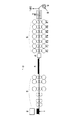
図4は、熱延鋼帯100の圧延工程を模式的に示す説明図である。連続鋳造機により製造されたスラブ1は、同図に示すように、加熱炉2に装入されて所定の温度に加熱される。スラブ1は加熱炉2により加熱された後、粗圧延機3により粗圧延を行われて被圧延材(以下「粗バー4」ともいう。)に薄く延ばされる。
FIG. 4 is an explanatory view schematically showing the rolling process of the hot-rolled
粗バー4は、図示しない搬送テーブルにより粗圧延機3から仕上げ圧延機5まで所定の搬送パターンで搬送される。この間に粗バー4は必要に応じて誘導加熱方式などの加熱装置6により加熱された後、複数スタンドから成る(図示例ではF1〜F7の7スタンド)仕上げ圧延機5により所定の板厚に仕上げ圧延され、続く冷却装置7により所定の巻き取り温度に冷却され、巻き取り機8でコイル9に巻き取られる。この巻き取り温度は、巻き取り機8の入口での熱延鋼帯100の温度である。
The
この時の仕上げ圧延機出側における熱延鋼帯の温度(以下、「仕上げ温度」ともいう。)は、熱延鋼帯100の機械的特性に大きく影響を及ぼす。特に炭素鋼を熱間圧延する場合、特性確保の観点から圧延温度をフェライト変態開始温度(Ar3温度)よりも高くする必要がある。仕上げ圧延中に被圧延材の温度がAr3変態温度以下となると、粗大粒や歪の蓄積により鋼板の強度、延性、靭性等の特性が劣化する可能性があり、仕上げ温度の下限値(仕上げ下限温度)が設定される。また、仕上げ圧延機の圧延ロールのロール肌荒れの関係から仕上げ温度の上限値(仕上げ上限温度)が決まっており、この仕上げ温度の下限値と上限値との間で目標とする機械特性値が得られるように仕上げ温度目標値が設定される。
At this time, the temperature of the hot-rolled steel strip on the delivery side of the finish rolling mill (hereinafter also referred to as “finishing temperature”) greatly affects the mechanical properties of the hot-rolled
熱延鋼帯の仕上げ圧延では、一般的に粗バーの長手方向の後方側(上流側)ほど、仕上げ圧延機に到達するまでの待ち時間が長くなるため、放熱による温度低下量が大きくなる。このため、以前より粗バーの先端部が仕上げ圧延機を通過した後に圧延速度を増加させる加速圧延を行うことにより、粗バーの長手方向の後方側の温度低下量を抑制し、仕上げ圧延機出側温度を全長にわたって確保するようにしていた。 In the finish rolling of a hot-rolled steel strip, the waiting time until reaching the finish rolling mill is generally longer toward the rear side (upstream side) of the rough bar in the longitudinal direction, so that the amount of temperature decrease due to heat radiation increases. For this reason, by performing accelerated rolling that increases the rolling speed after the leading end of the coarse bar has passed through the finish rolling mill, the amount of temperature decrease on the rear side in the longitudinal direction of the coarse bar is suppressed, and the finish rolling mill is discharged. The side temperature was ensured over the entire length.
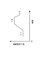
図5は、仕上げ圧延機5の通板速度の変更パターンの一例を示すグラフである。同図に示すように、仕上げ圧延機5の通板速度は、先端部の圧延不良を抑制するとともに、圧延時間の短縮も目的の一つとして先端部を圧延する際の通板速度V1から徐々に加速されて最高速度V2まで上昇され、その後に後端部を圧延する際の通板速度V3まで低下される。
FIG. 5 is a graph showing an example of a change pattern of the sheet feeding speed of the
ところで、上記熱延鋼帯の製造において、被圧延材は高温状態で搬送、圧延されるため、被圧延材の表面には酸化スケールが生成する。この酸化スケールは酸化鉄を主成分とするものであるが、金属酸化物を含むこともある。このような酸化スケール(以下において単に「スケール」ともいう。)が被圧延材の表面に存在したまま、熱間圧延を行うと、圧延時にスケールが鋼板表面に押し込まれて表面疵(一般に「うろこ状スケール」や「散砂状スケール」といわれる。)が発生する。特に、近年は熱延鋼帯の機械的性質の改善に伴い、その利用範囲が拡大されていることから高い表面品質へのニーズが高まり、スケールを原因とする表面品質劣化を防止することが重要となっている。 By the way, in manufacture of the said hot-rolled steel strip, since a to-be-rolled material is conveyed and rolled by a high temperature state, an oxide scale produces | generates on the surface of a to-be-rolled material. This oxide scale is composed mainly of iron oxide, but may contain a metal oxide. When hot rolling is performed while such an oxide scale (hereinafter, also simply referred to as “scale”) is present on the surface of the material to be rolled, the scale is pushed into the surface of the steel sheet during rolling, and surface defects (generally “scale” ”And“ sand scale ”. In particular, with the improvement of the mechanical properties of hot-rolled steel strips in recent years, the range of use has been expanded, so the need for high surface quality has increased and it is important to prevent surface quality deterioration due to scale. It has become.
こうした酸化スケール成長に起因するスケール欠陥の発生を抑制するため、仕上げ圧延機入側や仕上げスタンド間でデスケーリングを行ったり、被圧延材の表面温度を低くするための冷却等を行ったりすることが一般的であり、例えば特許文献1には仕上げスタンド間にある被圧延材の表面温度を規定する方法が、特許文献2には仕上げスタンド間でのデスケーラーと冷却装置との組み合わせにより酸化皮膜厚みを規定値以下にする方法が開示されている。
In order to suppress the generation of scale defects due to such oxide scale growth, descaling is performed between the entrance of the finishing mill and between the finishing stands, and cooling is performed to lower the surface temperature of the material to be rolled. For example,
さらに、通常スラブは加熱炉内においてスキッド上に保持された状態で加熱されるため、スキッドに接触している部分の温度が他の部分に比べて低下する加熱むらが発生する。この低温部分を「スキッドマーク」と称する。粗バーには加熱炉での加熱むらに起因するスキッドマークによる温度低下が長手方向に周期的に発生する。仕上げ温度は上下限内に入れるだけでなく極力均一な温度になることが望まれる。特許文献3や特許文献4には、仕上げ圧延機スタンド間での注水制御の方法や、粗圧延機と仕上げ圧延機間での誘導加熱によるスキッドマーク低減方法等が開示されている。
しかし、上記各特許文献に開示された方法においても被圧延材の表面温度や結果として得られる酸化皮膜厚みを規定値以下とするため、例えば被圧延材の長手方向のどの位置でデスケーリング装置及び冷却装置を使用するべきかが不明であり、加速圧延に応じたデスケーリング装置及び冷却装置の使い分けはなされていない。一般的にデスケーリング装置は噴射圧力、応答性が大きいが流量は小さく、被圧延材の表面冷却用の冷却装置は逆に噴射圧力、応答性は小さいが流量は大きく冷却能力は優れている。結果的に先端部通板時の圧延速度とある一定のレートで加速する加速圧延中(一般に4〜40mpm/s程度)、尾端部通板時の圧延速度では各々の圧延速度に応じて応答性、冷却能力により、仕上げ温度変動防止のために使い分ける必要がある。しかし、その方法は不明瞭であり、仕上げ圧延温度変動が残存、追従遅れが発生してしまうこととなる。 However, even in the methods disclosed in the above patent documents, in order to make the surface temperature of the material to be rolled and the resulting oxide film thickness below a specified value, for example, at any position in the longitudinal direction of the material to be rolled, It is unclear whether the cooling device should be used, and the descaling device and the cooling device corresponding to accelerated rolling are not used properly. In general, the descaling device has a large injection pressure and responsiveness, but the flow rate is small. On the other hand, a cooling device for surface cooling of the material to be rolled has a small injection pressure and responsiveness, but has a large flow rate and excellent cooling ability. As a result, during the accelerated rolling (generally about 4 to 40 mpm / s) that accelerates at a certain rate with the rolling speed at the time of passing the tip part, the rolling speed at the time of passing the tail end part responds according to each rolling speed. Depending on the characteristics and cooling capacity, it is necessary to use them properly to prevent fluctuations in the finishing temperature. However, the method is unclear, and the finish rolling temperature fluctuation remains and a follow-up delay occurs.
つまり、表面の酸化スケール除去のためには高圧水であるデスケーラーの使用が有効であるが、被圧延材の表面温度低下には冷却装置(以下「スプレー」ともいう。)の使用が有効である。加速圧延中の応答性を要求される場合は、長手方向の圧延速度への追従の点からは、デスケーラーを用いないと仕上げ温度の上昇を招いてしまう。最高速度に到達すると今度は応答性でなく冷却能の大きな冷却装置を用いないと冷却不足となり仕上げ温度の上昇を招くことになる。しかし、例えば冷却能力を確保するために噴射圧力を高めるだけでは特に被圧延材が圧延機に噛み込む際に上反りや下反り等の形状(平坦)崩れを引き起こす懸念もあり、先端通板時にはむやみに噴射圧力を上げることはできない。 That is, the use of a descaler that is high-pressure water is effective for removing the oxide scale on the surface, but the use of a cooling device (hereinafter also referred to as “spray”) is effective for lowering the surface temperature of the material to be rolled. . When responsiveness during accelerated rolling is required, the finish temperature rises unless a descaler is used from the standpoint of following the rolling speed in the longitudinal direction. When the maximum speed is reached, this time, if it is not responsive and a cooling device with a large cooling capacity is not used, cooling will be insufficient and the finishing temperature will rise. However, for example, when the injection pressure is only increased to ensure the cooling capacity, there is a concern that the material to be rolled will cause a shape (flat) collapse such as upper warping or lower warping when biting into the rolling mill. The injection pressure cannot be increased unnecessarily.
ここに、本発明の課題は、表面疵の発生を抑制しながら、仕上げ温度を全長にわたって目標値に制御することが可能な熱延鋼板の製造方法及びその装置を提供することにある。 Here, the subject of this invention is providing the manufacturing method and apparatus of a hot-rolled steel plate which can control finishing temperature to a target value over a full length, suppressing generation | occurrence | production of surface flaws.
本発明者らは、上記課題を解決するために種々の実験を行い、以下の知見を得た。
(1)少なくとも1つの仕上げスタンド間に噴射圧力が5〜20MPaのデスケーリング装置と噴射圧力が0.1〜2.0MPaの冷却装置とをそれぞれ複数設ける。そして、長手方向の圧延速度の変化に応じ、デスケーリング装置と冷却装置を使い分ける。これにより表面疵の発生を抑制しながら仕上げ温度を全長にわたって目標値に制御することができる。
冷却装置を複数設置するのは以下の理由による。すなわち、表面疵の発生を抑制するには、特定圧延機間での冷却水量の増加が必要となるが、冷却装置を大型化して冷却水量を増加させると、長手方向の鋼板温度変動が大きくなるからである。また、スタンド間に冷却装置を複数台設け、それぞれの冷却装置の冷却水量の増加を抑制し、全体として冷却水量を増加させることにより、表面疵の発生を抑制しながら温度変動を抑制することができるからである。
デスケーリング装置を複数設置するのは以下の理由による。すなわち、表面疵の発生を抑制するには、特定圧延機間でのデスケーリング性の向上が必要となるが、デスケーリング圧力を高めると鋼板温度変動が大きくなるといった問題や通板性が悪化するといった欠点がある。一方、スタンド間にデスケーリング装置を複数台設け、それぞれのデスケーリング圧力の増大を抑制し、全体としてデスケーリング性を高めることにより、表面疵の発生を抑制しながら温度変動を抑制することができるからである。
(2)表1にデスケーリング装置及び冷却装置の性能概要を示す。
The present inventors conducted various experiments to solve the above-mentioned problems, and obtained the following knowledge.
(1) A plurality of descaling devices having an injection pressure of 5 to 20 MPa and cooling devices having an injection pressure of 0.1 to 2.0 MPa are provided between at least one finishing stand. And according to the change of the rolling speed of a longitudinal direction, a descaling apparatus and a cooling device are used properly. Thus, the finishing temperature can be controlled to the target value over the entire length while suppressing the generation of surface flaws.
The reason for installing a plurality of cooling devices is as follows. That is, in order to suppress the occurrence of surface flaws, it is necessary to increase the amount of cooling water between specific rolling mills. However, when the cooling device is increased in size to increase the amount of cooling water, the longitudinal steel plate temperature fluctuation increases. Because. In addition, by providing a plurality of cooling devices between the stands, suppressing an increase in the cooling water amount of each cooling device, and increasing the cooling water amount as a whole, it is possible to suppress temperature fluctuations while suppressing the occurrence of surface flaws. Because it can.
The reason for installing multiple descaling devices is as follows. That is, in order to suppress the occurrence of surface flaws, it is necessary to improve the descaling property between specific rolling mills, but the problem that the steel plate temperature fluctuation increases when the descaling pressure is increased and the plate passing property deteriorate. There are disadvantages. On the other hand, by providing a plurality of descaling devices between the stands and suppressing an increase in the respective descaling pressure and improving the descaling performance as a whole, temperature fluctuations can be suppressed while suppressing the occurrence of surface flaws. Because.
(2) Table 1 shows an outline of the performance of the descaling device and the cooling device.

一般にデスケーリング装置は噴射圧力が高く、給水配管内を常に高圧状態で維持しているため開閉の応答性は非常に良い。したがって、鋼帯表面にスケール除去には効果大であるが、反面噴射される流量自体は小さいためそれに応じて鋼帯の冷却能力は小さい。一方、冷却装置は、デスケーリング装置に比べて噴射圧力が小さく、スケール除去能力はない。しかし、噴射流量は大きいので、鋼帯冷却能力は大きい。
(3)したがって、例えば、圧延速度の低い先端部には、デスケーリング装置のみ、あるいはデスケーリング装置と冷却装置とを用いる。
(4)加速圧延中は、デスケーリング装置の使用数を増加する。これにより、仕上げ温度の追従遅れが防止される。
(5)圧延速度が最高速度に到達し一定の場合には、冷却装置の使用数を増加させる。これにより仕上げ温度が上限を超えるのが抑制される。
(6)圧延速度の低い先端部では、噴射圧力を低くし、速度の増加に伴い噴射圧力を増加させる。
In general, the descaling device has a high injection pressure, and the responsiveness of opening and closing is very good because the inside of the water supply pipe is always maintained in a high pressure state. Therefore, although it is effective for removing the scale on the surface of the steel strip, on the other hand, the injected flow rate itself is small, so the cooling capacity of the steel strip is small accordingly. On the other hand, the cooling device has a smaller injection pressure than the descaling device and does not have a scale removal capability. However, since the injection flow rate is large, the steel strip cooling capacity is large.
(3) Therefore, for example, only the descaling device or the descaling device and the cooling device is used for the tip portion having a low rolling speed.
(4) The number of descaling devices used is increased during accelerated rolling. Thereby, the follow-up delay of the finishing temperature is prevented.
(5) When the rolling speed reaches the maximum speed and is constant, the number of cooling devices used is increased. Thereby, it is suppressed that finishing temperature exceeds an upper limit.
(6) At the tip portion where the rolling speed is low, the injection pressure is lowered, and the injection pressure is increased as the speed increases.
以下、本発明について説明する。なお、本発明の理解を容易にするために添付図面の参照符号を括弧書きで付記するが、それにより本発明が図示の形態に限定されるものではない。 The present invention will be described below. In addition, in order to make an understanding of this invention easy, the reference symbol of an accompanying drawing is attached in parenthesis, However, This invention is not limited to the form of illustration by it.
本発明の第1の態様は、粗圧延機(3)でスラブ(1)に粗圧延を施して被圧延材(4)とするとともに、その被圧延材を複数のスタンド(F1〜F7)を備えた仕上げ圧延機(5)で圧延して熱延鋼帯(100)を製造する方法であって、仕上げ圧延機の少なくとも一つのスタンド間(F1/F2間、又はF2/F3間)にデスケーリング装置(11)と冷却装置(12)とをそれぞれ複数設置し、仕上げ圧延機における圧延速度に応じてデスケーリング装置と冷却装置のそれぞれの使用数を変化させることにより、被圧延材の仕上げ圧延機出側での表面温度を所定の範囲に制御することを特徴とする熱延鋼帯の製造方法である。 In the first aspect of the present invention, the slab (1) is subjected to rough rolling by a rough rolling mill (3) to obtain a material to be rolled (4), and the material to be rolled is provided with a plurality of stands (F1 to F7). A method of producing a hot-rolled steel strip (100) by rolling with a finish rolling mill (5) provided, wherein the hot-rolled steel strip (100) is produced between at least one stand (between F1 / F2 or between F2 / F3) of the finishing mill. A plurality of scaling devices (11) and cooling devices (12) are installed, and the rolling of the material to be rolled is finished by changing the number of each of the descaling device and the cooling device according to the rolling speed in the finishing mill. A method for producing a hot-rolled steel strip, characterized in that the surface temperature on the machine exit side is controlled within a predetermined range.
この熱延鋼帯の製造方法によれば、スタンド間にそれぞれ複数ずつ設けられたデスケーリング装置と冷却装置とのそれぞれの使用数を鋼帯の圧延状況に応じて使い分けることにより、表面疵の発生を抑制しながら、仕上げ温度を全長にわたって目標値に制御することが可能となる。 According to this method of producing a hot-rolled steel strip, surface flaws are generated by properly using a plurality of descaling devices and cooling devices provided between the stands according to the rolling condition of the steel strip. It is possible to control the finishing temperature to the target value over the entire length while suppressing.
上記第1の態様にかかる熱延鋼帯(100)の製造方法において、さらに、圧延速度の変化に応じてデスケーリング装置(11)及び/又は冷却装置(12)の噴射圧力を調整することが好ましい。 In the manufacturing method of the hot-rolled steel strip (100) according to the first aspect, the injection pressure of the descaling device (11) and / or the cooling device (12) may be further adjusted according to the change in the rolling speed. preferable.
このようにすれば、仕上げ温度をさらに正確に制御することが可能となる。 In this way, the finishing temperature can be controlled more accurately.
また、上記第1の態様にかかる熱延鋼帯(100)の製造方法(変形例を含む。)において、仕上げ圧延機(5)の入り側にデスケーリング装置(11)を設けるとともに、該デスケーリング装置と粗圧延機(3)との間に誘導加熱装置(6)を設け、該誘導加熱装置により被圧延材を板幅方向全幅にわたって加熱することも好ましい。 Moreover, in the manufacturing method (including modifications) of the hot-rolled steel strip (100) according to the first aspect, a descaling device (11) is provided on the entrance side of the finish rolling mill (5), and It is also preferable to provide an induction heating device (6) between the scaling device and the rough rolling mill (3), and to heat the material to be rolled over the entire width in the sheet width direction by the induction heating device.
特に板厚の薄い熱延鋼帯の場合、粗バーが仕上げ圧延機により圧延される際に先端部を通過後に加速圧延となるので、先端部での温度降下量が大となる。しかし、このようにすれば、先端部の温度低下を下限値以上に確保することができるとともに、加熱炉内で生じるスキッドマークの低温部への集中加熱により、スキッドマークの低減が可能となる。これにより、冷却装置の応答を含めた誤差に対する対応が可能となり、結果的に仕上げ圧延機出側における長手方向の温度変動の少ない熱延鋼帯を得ることができる。 In particular, in the case of a hot-rolled steel strip having a thin plate thickness, accelerated rolling is performed after passing through the tip when the rough bar is rolled by a finish rolling mill, resulting in a large temperature drop at the tip. However, if this is done, the temperature drop at the tip portion can be secured above the lower limit value, and the skid mark can be reduced by the concentrated heating of the skid mark in the heating furnace to the low temperature portion. Thereby, it becomes possible to cope with errors including the response of the cooling device, and as a result, a hot-rolled steel strip with little temperature fluctuation in the longitudinal direction on the exit side of the finishing mill can be obtained.
さらに、上記第1の態様にかかる熱延鋼帯(100)の製造方法(変形例を含む。)において、デスケーリング装置(11)と冷却装置(12)とは、仕上げ圧延機の入り側第1スタンドと第2スタンドとの間、及び/又は第2スタンドと第3スタンドとの間に設置することが好ましい。 Furthermore, in the manufacturing method (including modifications) of the hot-rolled steel strip (100) according to the first aspect, the descaling device (11) and the cooling device (12) are provided on the entry side of the finish rolling mill. It is preferable to install between the first stand and the second stand and / or between the second stand and the third stand.
この様な構成によって、仕上げ前段スタンド(F1〜F3)でのスケール除去が可能になる。また、この範囲では板厚が厚いので、デスケール用の高圧水(5〜20MPa)の適用が容易である。また、熱間圧延において板平坦形状を安定させるために比較的大きな圧下率をとる前段スタンドにおけるロールの肌荒れを抑制することが可能となる。さらに、デスケーリング装置により表面スケールを除去した後、直ちに冷却装置により冷却することにより、冷却の効率を高めることもできる。 With such a configuration, it is possible to remove the scale at the stand before finishing (F1 to F3). Moreover, since the plate thickness is thick in this range, it is easy to apply high-pressure water (5 to 20 MPa) for descaling. Further, it is possible to suppress the rough surface of the roll in the front stand having a relatively large reduction ratio in order to stabilize the flat plate shape in the hot rolling. Furthermore, after removing the surface scale by the descaling device, the cooling efficiency can be increased by immediately cooling by the cooling device.
本発明の第2の態様は、粗圧延機(3)と、該粗圧延機の下流側に配置されるとともに複数のスタンド(F1〜F7)を有する仕上げ圧延機(5)とを備える熱延鋼帯(100)の製造装置であって、仕上げ圧延機の少なくとも一つのスタンド間にデスケーリング装置(11)と冷却装置(12)とをそれぞれ複数備えることを特徴とする熱延鋼帯の製造装置である。 A 2nd aspect of this invention is a hot rolling provided with a rough rolling mill (3) and a finish rolling mill (5) which is arrange | positioned in the downstream of this rough rolling mill and has a some stand (F1-F7). An apparatus for manufacturing a steel strip (100), comprising a plurality of descaling devices (11) and a plurality of cooling devices (12) between at least one stand of a finish rolling mill. Device.
上記第2の態様にかかる熱延鋼帯の製造装置において、さらに、仕上げ圧延機の入り側にデスケーリング装置を備えるとともに、該デスケーリング装置と粗圧延機との間に誘導加熱装置を設けてもよい。 In the apparatus for producing a hot-rolled steel strip according to the second aspect, a descaling device is further provided on the entrance side of the finish rolling mill, and an induction heating device is provided between the descaling device and the roughing mill. Also good.
本発明の熱延鋼帯の製造方法によれば、仕上げ圧延機の少なくとも一つ以上のスタンド間に圧力、流量レベルの異なるデスケーリング装置、冷却装置を複数配置し、被圧延材の圧延速度に応じて最適な冷却装置を使い分けることにより、結果的にコイル長手方向での表面疵の発生を抑制しながら、かつ被圧延材の仕上げ圧延機出側での表面温度を追従遅れなく所定の目標値に制御することが可能となる。これにより、表面疵発生を防ぎ、機械特性に優れた熱延鋼帯を製造することができる。本発明のこのような作用及び利得は、次に説明する発明を実施するための最良の形態から明らかにされる。 According to the method for producing a hot-rolled steel strip of the present invention, a plurality of descaling devices and cooling devices having different pressure and flow rate levels are arranged between at least one stand of a finish rolling mill, so that the rolling speed of the material to be rolled is increased. Depending on the optimum cooling device, the surface temperature at the exit side of the finished rolling mill of the material to be rolled can be controlled to a predetermined target value while suppressing the occurrence of surface flaws in the coil longitudinal direction. It becomes possible to control to. Thereby, surface flaw generation can be prevented and a hot-rolled steel strip excellent in mechanical properties can be produced. Such an operation and gain of the present invention will be made clear from the best mode for carrying out the invention described below.
以下、本発明にかかる熱延鋼板の製造方法の実施形態を、添付図面を参照しながら詳細に説明する。 Hereinafter, an embodiment of a method for producing a hot-rolled steel sheet according to the present invention will be described in detail with reference to the accompanying drawings.
連続鋳造機により、厚みが例えば250mm程度のスラブ1(図4参照)が製造される。製造されたスラブ1は、加熱炉2に装入されて所定の温度に加熱される。スラブ1は加熱炉2により加熱された後、粗圧延機3により粗圧延を行われて、板厚が例えば30mm程度の粗バー4に薄く引き延ばされる。この粗バー4は、必要に応じて誘導加熱装置6により加熱された後、複数スタンドからなる仕上げ圧延機5により所定の板厚に仕上げ圧延され、続く冷却装置7により所定の巻き取り温度に冷却され、巻き取り機8でコイル9に巻き取られる。
The slab 1 (see FIG. 4) having a thickness of about 250 mm is manufactured by the continuous casting machine. The manufactured
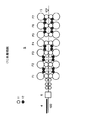
図1は、仕上げ圧延機入側から圧延機出側の間に設置されたデスケーリング装置と冷却装置の配置例を示している。この配置列は、F1−F2間とF2−F3間にそれぞれ2組のデスケーリング装置11を備え、さらにF4−F5間を除く全てのスタンド間のそれぞれに2組の冷却装置12を備えている。
FIG. 1 shows an arrangement example of a descaling device and a cooling device installed between the finishing mill entry side and the rolling mill exit side. This arrangement row includes two sets of
図1において、粗バー4は必要に応じて誘導加熱装置6により加熱された後、仕上げ圧延機5で仕上げ圧延される前に、粗バー4表面のスケールを除去、及び仕上げ温度上昇防止のために仕上げ圧延機5の入側に設けた3組のデスケーリング装置11、11、11によりスケール除去が行われる。
In FIG. 1, the
仕上げ圧延開始後はスタンド間に設けたデスケーリング装置11によるスケール除去とともに冷却装置12により、鋼帯表面温度の調整が行われる。この仕上げ圧延機間での鋼帯冷却を、「スタンド間冷却」ともいう。
After finishing rolling, the steel strip surface temperature is adjusted by the cooling
被圧延材の長手方向の仕上げ温度が製品である熱延鋼帯100の機械的特性に応じて定まる仕上げ下限温度以上となるとともに、圧延ロールのロール肌荒れ防止のため定められた仕上げ上限温度以下となるように、図5に示す仕上げ圧延機速度パターンに基づいて、誘導加熱装置6による昇温、仕上げ前や仕上げスタンド間でのデスケーリング、スタンド間冷却の各条件が決定される。
The finishing temperature in the longitudinal direction of the material to be rolled is equal to or higher than the finishing lower limit temperature determined according to the mechanical properties of the hot-rolled
仕上げ圧延機速度パターンは予め決められているため、仕上げ温度を目標値に制御するために、仕上げスタンドF1〜F7間でのデスケーリング装置11と冷却装置12(スタンド間スプレー)の使用数、並びに噴射圧力が設定される。仕上げ温度の下限値確保のためには仕上げスタンド間でのデスケーリング装置11と冷却装置12(スタンド間スプレー)の使用数を減少させる。さらに、噴射圧力を小さくして流量を減少させる。さらに誘導加熱装置6により被圧延材を加熱するのが望ましい。反面、仕上げ温度を上限値以下とするためには、圧延機速度パターンである加速圧延に追従して、各冷却装置12の使用数を増加させ、噴射圧力を増加して流量を増加させる。
Since the finishing mill speed pattern is predetermined, in order to control the finishing temperature to the target value, the number of
(第1実施形態)
圧延速度の低い長手方向先端部では、デスケーリング装置11のみ若しくは冷却装置12を併用して熱延鋼帯100の表面スケール除去と表面温度上限以下確保を行い、仕上げ圧延機5が加速を開始すると応答性の良いデスケーリング装置11の使用数を追加することにより、長手方向の仕上げ温度の追従遅れを防止させる。
(First embodiment)
At the front end of the longitudinal direction where the rolling speed is low, only the
仕上げ圧延機5が最高速度に到達して圧延速度が一定となると、冷却能力の高い冷却装置12の使用数を増加することにより長手方向での仕上げ温度の上限以上となることを防止する。
When the finishing
なお、粗バー誘導加熱装置6、仕上げ圧延機出側温度予測装置、圧延ラインの速度制御を行う圧延ライン制御装置、デスケーリング装置11・冷却装置12の出力を制御する演算装置により、仕上げ圧延機5出側での熱延鋼帯100の温度を予測演算し、各冷却装置12に制御信号を出力する。
In addition, the finish rolling mill includes a rough bar
(第2実施形態)
第1実施形態と同様に、圧延速度の低い長手方向の先端部では、デスケーリング装置11のみ若しくは冷却装置12を併用して熱延鋼帯100の表面スケール除去と表面温度上限以下確保を行う。仕上げ圧延機5が加速を開始すると応答性の良いデスケーリング装置11の使用数追加で長手方向の仕上げ温度追従遅れを防止させ、仕上げ圧延機5が最高速度に到達して圧延速度が一定となった際は冷却能力の高い冷却装置12の使用数を増加することにより長手方向での仕上げ温度上限以下を確保する。
(Second Embodiment)
Similarly to the first embodiment, at the front end portion in the longitudinal direction where the rolling speed is low, only the
この際、被圧延材の板厚や圧延速度量に対応して冷却装置12の冷却能力不足を防止するため、噴射圧力を可変とさせ圧力を増大させることで冷却能力を増加させることが好ましい。被圧延材の長手方向で先端部が圧延機に噛み込む際には圧延速度を低く、かつ、上反り、下反りを防止するため噴射圧力を低く設定する。圧延速度が上がり最高速度に到達すると各冷却装置12の使用数の増加に加えて、噴射圧力を増加させることにより、冷却能力の増大をはかることができる。
At this time, it is preferable to increase the cooling capacity by making the injection pressure variable and increasing the pressure in order to prevent insufficient cooling capacity of the
(第3実施形態)
仕上げ圧延機出側温度を長手方向に一定化させるため、上記第1実施形態及び第2実施形態に示すスタンド間の冷却に加え、仕上げ圧延機入側での誘導加熱装置6により被圧延材を加熱する。特に板厚の薄い熱延鋼帯の場合、粗バー4が仕上げ圧延機5により圧延される際に先端部を通過後に加速圧延となるので、先端部での温度降下量が大となる。先端部の温度低下を誘導加熱により下限値以上に確保することができるとともに、加熱炉2(図4参照)内で生じるスキッドマークの低温部への集中加熱により、スキッドマークの低減が可能となる。これにより、冷却装置12の応答を含めた誤差に対する対応が可能となり、結果的に仕上げ圧延機出側における長手方向の温度変動の少ない熱延鋼帯が得られる。
(Third embodiment)
In order to make the finishing mill exit temperature constant in the longitudinal direction, in addition to the cooling between the stands shown in the first and second embodiments, the material to be rolled is fed by the
図1に示す基本構成の装置列を用い、先端部を誘導加熱装置6で加熱後、圧延速度に応じてデスケーリング装置11と冷却装置12の使用数並びにその噴射圧力を調整して仕上げ温度を制御する試験を実施した。対象材は、低炭素鋼で仕上げ圧延機出側での板厚は1.6mm、板幅は1150mmであり、仕上げ出側温度の目標値は830℃(上下限±15℃)である。先端部通板速度は約640mpm、加速率40mpm/s、最高速度は1600mpmであり、仕上げ入側での誘導加熱装置6を使用した。
1 is used, and after heating the tip portion with the
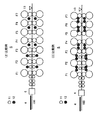
図2に、比較例にかかる仕上げ圧延機入側、圧延機間に設置された各種冷却装置(デスケーリング装置11、冷却装置12)の配置の例を示す。比較例(2)は、F1−F2間、F2−F3間、F3−F4間、F5−F6間、F6−F7間に1組の冷却装置12を設け、F1−F2間、F2−F3間に1組のデスケーリング装置11を設けた。それ以外は図1と同じ構成とした。比較例(3)は、F1−F2間、F2−F3間に1組のデスケーリング装置11を設けた。それ以外は図1と同じ構成とした。
In FIG. 2, the example of arrangement | positioning of the various cooling devices (descaling
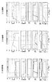
図3に本発明例(1)と比較例(2)、(3)における試験結果を示す。各図の横軸は、コイルの長手位置を示している。また、縦軸はそれぞれ上段から、温度(仕上げ出側温度、「FT」と記載)、誘導加熱装置6の投入電力、デスケーリング装置11の使用本数(「デスケ本数」と記載)、冷却装置12の本数(「スプレー本数」と記載)、冷却装置12の噴射圧力(供給ポンプの圧力を「供給水圧力」と記載)、仕上げ圧延機最終スタンド速度(F7速度)を示す。
FIG. 3 shows the test results in Example (1) of the present invention and Comparative Examples (2) and (3). The horizontal axis of each figure has shown the longitudinal position of the coil. Also, the vertical axis indicates the temperature (finishing exit side temperature, described as “FT”), the input power of the
図3に示すように、本発明例(1)は、全長にわたり、仕上げ温度を目標温度範囲内に制御することができた。また、表面疵の発生もなかった。 As shown in FIG. 3, the present invention example (1) was able to control the finishing temperature within the target temperature range over the entire length. Moreover, there was no generation of surface defects.
比較例(2)、(3)では、加速圧延中の追従遅れ、並びに最高速度到達後の冷却不足により仕上げ温度が目標温度範囲外れとなった。 In Comparative Examples (2) and (3), the finishing temperature was out of the target temperature range due to the following delay during accelerated rolling and insufficient cooling after reaching the maximum speed.
本発明により、薄物材の熱延鋼帯で先端部では誘導加熱装置6の昇温を活用し、圧延機加速開始後は応答性の良いデスケーリング装置11を補助的冷却装置として用いて追従遅れを防止し、最高速度到達後は冷却能の大きい冷却装置12(スプレー)を用いるとともに、その噴射圧力を長手方向の圧延速度に応じて可変とすることによって、仕上げ圧延機出側での仕上げ温度を全長にわたって精度良く目標値に制御することが可能となった。
According to the present invention, the hot-rolled steel strip of a thin material utilizes the temperature rise of the
以上、現時点において、最も、実践的であり、かつ、好ましいと思われる実施形態に関連して本発明を説明したが、本発明は、本願明細書中に開示された実施形態に限定されるものではなく、請求の範囲及び明細書全体から読み取れる発明の要旨あるいは思想に反しない範囲で適宜変更可能であり、そのような変更を伴う熱延鋼板の製造方法及びその装置もまた本発明の技術的範囲に包含されるものとして理解されなければならない。 Although the present invention has been described with reference to the most practical and preferred embodiments at the present time, the invention is limited to the embodiments disclosed herein. However, the invention can be changed as appropriate without departing from the spirit or concept of the invention that can be read from the claims and the entire specification, and a method and an apparatus for manufacturing a hot-rolled steel sheet with such changes are also included in the technical scope of the present invention. It should be understood as encompassed by the scope.
V1 先端部通板速度
V2 最高速度
V3 尾端部通板速度
1 スラブ
2 加熱炉
3 粗圧延機
4 粗バー
5 仕上げ圧延機
6 誘導加熱装置
7 圧延後冷却装置
8 巻き取り機
9 コイル
10 圧延工程全体
11 デスケーリング装置
12 冷却装置
13 仕上げ圧延機出側温度計
100 熱延鋼帯
V1 Tip passage speed V2 Maximum speed V3
Claims (7)
The descaling device and the cooling device are provided between the first stand and the second stand on the entrance side of the finish rolling mill and / or between the second stand and the third stand. The apparatus for manufacturing a hot-rolled steel strip according to claim 5 or 6.
Priority Applications (1)
| Application Number | Priority Date | Filing Date | Title |
|---|---|---|---|
| JP2004113535A JP2005296973A (en) | 2004-04-07 | 2004-04-07 | Manufacturing method and apparatus for hot-rolled steel sheet |
Applications Claiming Priority (1)
| Application Number | Priority Date | Filing Date | Title |
|---|---|---|---|
| JP2004113535A JP2005296973A (en) | 2004-04-07 | 2004-04-07 | Manufacturing method and apparatus for hot-rolled steel sheet |
Publications (1)
| Publication Number | Publication Date |
|---|---|
| JP2005296973A true JP2005296973A (en) | 2005-10-27 |
Family
ID=35329155
Family Applications (1)
| Application Number | Title | Priority Date | Filing Date |
|---|---|---|---|
| JP2004113535A Pending JP2005296973A (en) | 2004-04-07 | 2004-04-07 | Manufacturing method and apparatus for hot-rolled steel sheet |
Country Status (1)
| Country | Link |
|---|---|
| JP (1) | JP2005296973A (en) |
Cited By (10)
| Publication number | Priority date | Publication date | Assignee | Title |
|---|---|---|---|---|
| CN103042055A (en) * | 2012-12-27 | 2013-04-17 | 攀钢集团西昌钢钒有限公司 | Hot-rolled billet steel rough-rolling descaling method |
| JP2014214324A (en) * | 2013-04-23 | 2014-11-17 | Jfeスチール株式会社 | Method for manufacturing hot rolled steel plate |
| CN104226683A (en) * | 2014-09-24 | 2014-12-24 | 首钢总公司 | Method for solving surface color difference defect of hot-rolled pickled plates |
| WO2020184372A1 (en) * | 2019-03-11 | 2020-09-17 | 日本製鉄株式会社 | Hot-rolled steel sheet |
| WO2020184356A1 (en) * | 2019-03-11 | 2020-09-17 | 日本製鉄株式会社 | Hot-rolled steel sheet |
| CN113996656A (en) * | 2021-10-30 | 2022-02-01 | 日照宝华新材料有限公司 | Iron scale control device and method for low-carbon low-silicon plate strip production line |
| EP4101552A1 (en) * | 2021-06-09 | 2022-12-14 | Primetals Technologies Austria GmbH | Method for producing of a microalloyed steel, a microalloyed steel produced by means of the method, and an integrated casting-rolling system |
| CN116060463A (en) * | 2021-11-01 | 2023-05-05 | 宝山钢铁股份有限公司 | A Variable Descaling Control Method Between Stands of Hot Continuous Rolling Finishing Mill |
| CN116900049A (en) * | 2023-07-26 | 2023-10-20 | 江苏省沙钢钢铁研究院有限公司 | Production method for improving surface quality of hot-rolled strip steel |
| CN117019869A (en) * | 2023-06-28 | 2023-11-10 | 首钢京唐钢铁联合有限责任公司 | A kind of preparation method of 65Mn steel plate |
-
2004
- 2004-04-07 JP JP2004113535A patent/JP2005296973A/en active Pending
Cited By (16)
| Publication number | Priority date | Publication date | Assignee | Title |
|---|---|---|---|---|
| CN103042055B (en) * | 2012-12-27 | 2015-06-10 | 攀钢集团西昌钢钒有限公司 | Hot-rolled billet steel rough-rolling descaling method |
| CN103042055A (en) * | 2012-12-27 | 2013-04-17 | 攀钢集团西昌钢钒有限公司 | Hot-rolled billet steel rough-rolling descaling method |
| JP2014214324A (en) * | 2013-04-23 | 2014-11-17 | Jfeスチール株式会社 | Method for manufacturing hot rolled steel plate |
| CN104226683A (en) * | 2014-09-24 | 2014-12-24 | 首钢总公司 | Method for solving surface color difference defect of hot-rolled pickled plates |
| US12503743B2 (en) | 2019-03-11 | 2025-12-23 | Nippon Steel Corporation | Hot-rolled steel sheet |
| WO2020184372A1 (en) * | 2019-03-11 | 2020-09-17 | 日本製鉄株式会社 | Hot-rolled steel sheet |
| WO2020184356A1 (en) * | 2019-03-11 | 2020-09-17 | 日本製鉄株式会社 | Hot-rolled steel sheet |
| JPWO2020184356A1 (en) * | 2019-03-11 | 2021-10-21 | 日本製鉄株式会社 | Hot-rolled steel sheet |
| JPWO2020184372A1 (en) * | 2019-03-11 | 2021-10-21 | 日本製鉄株式会社 | Hot-rolled steel sheet |
| JP7111246B2 (en) | 2019-03-11 | 2022-08-02 | 日本製鉄株式会社 | hot rolled steel |
| EP4101552A1 (en) * | 2021-06-09 | 2022-12-14 | Primetals Technologies Austria GmbH | Method for producing of a microalloyed steel, a microalloyed steel produced by means of the method, and an integrated casting-rolling system |
| CN113996656A (en) * | 2021-10-30 | 2022-02-01 | 日照宝华新材料有限公司 | Iron scale control device and method for low-carbon low-silicon plate strip production line |
| CN113996656B (en) * | 2021-10-30 | 2023-12-05 | 日照宝华新材料有限公司 | An iron oxide scale control device and method for a low-carbon and low-silicon plate and strip production line |
| CN116060463A (en) * | 2021-11-01 | 2023-05-05 | 宝山钢铁股份有限公司 | A Variable Descaling Control Method Between Stands of Hot Continuous Rolling Finishing Mill |
| CN117019869A (en) * | 2023-06-28 | 2023-11-10 | 首钢京唐钢铁联合有限责任公司 | A kind of preparation method of 65Mn steel plate |
| CN116900049A (en) * | 2023-07-26 | 2023-10-20 | 江苏省沙钢钢铁研究院有限公司 | Production method for improving surface quality of hot-rolled strip steel |
Similar Documents
| Publication | Publication Date | Title |
|---|---|---|
| WO2011111663A1 (en) | Hot-rolled steel sheet manufacturing method and manufacturing device | |
| KR20130099091A (en) | Method for producing steel strips by continuous rolling or semi-continuous rolling | |
| US20130263634A1 (en) | Rolling mill for producing steel for tubes and thin strip | |
| JP6137109B2 (en) | Rough rolling method for hot-rolled steel sheet | |
| JP5577655B2 (en) | Hot-rolled steel sheet cooling equipment and cooling method | |
| JP2005296973A (en) | Manufacturing method and apparatus for hot-rolled steel sheet | |
| JP6233613B2 (en) | Production line for hot-rolled steel strip and method for producing hot-rolled steel strip | |
| JP5609407B2 (en) | Manufacturing method and manufacturing equipment for hot-rolled steel sheet | |
| JP3551129B2 (en) | Manufacturing method and manufacturing equipment for hot rolled steel strip | |
| JP6233614B2 (en) | Production line for hot-rolled steel strip and method for producing hot-rolled steel strip | |
| JP2002178004A (en) | Hot rolling equipment and method for hot rolled steel strip | |
| JP2005169454A (en) | Steel strip manufacturing equipment and manufacturing method | |
| JP4552731B2 (en) | Hot rolling method for steel strip | |
| JP4054328B2 (en) | Hot rolled long coil manufacturing method | |
| JP3698088B2 (en) | Manufacturing method of hot-rolled steel strip | |
| JP5609703B2 (en) | Manufacturing method of hot-rolled steel sheet | |
| JP5839181B2 (en) | Method for cooling hot steel sheet and its cooling equipment | |
| JP3620464B2 (en) | Manufacturing method and manufacturing apparatus for hot-rolled steel sheet | |
| JP3975954B2 (en) | Conveying method of hot-rolled steel strip | |
| JP5935541B2 (en) | Manufacturing method of hot-rolled steel sheet | |
| JP4065251B2 (en) | Hot finish rolling method that prevents drawing wrinkles | |
| JP2005296978A (en) | Manufacturing method and equipment for thick steel plate | |
| JP2012250281A (en) | Method for cooling hot-rolled steel sheet | |
| RU2686504C1 (en) | Method for production of rolled strip on wide-band rolling mill | |
| JP3307213B2 (en) | Hot rolled steel strip manufacturing method |
Legal Events
| Date | Code | Title | Description |
|---|---|---|---|
| A621 | Written request for application examination |
Effective date: 20060626 Free format text: JAPANESE INTERMEDIATE CODE: A621 |
|
| A977 | Report on retrieval |
Free format text: JAPANESE INTERMEDIATE CODE: A971007 Effective date: 20061121 |
|
| A131 | Notification of reasons for refusal |
Free format text: JAPANESE INTERMEDIATE CODE: A131 Effective date: 20081014 |
|
| A521 | Written amendment |
Effective date: 20081212 Free format text: JAPANESE INTERMEDIATE CODE: A523 |
|
| A02 | Decision of refusal |
Effective date: 20090120 Free format text: JAPANESE INTERMEDIATE CODE: A02 |