JP5609096B2 - Blank media and transfer foil - Google Patents
Blank media and transfer foil Download PDFInfo
- Publication number
- JP5609096B2 JP5609096B2 JP2009284216A JP2009284216A JP5609096B2 JP 5609096 B2 JP5609096 B2 JP 5609096B2 JP 2009284216 A JP2009284216 A JP 2009284216A JP 2009284216 A JP2009284216 A JP 2009284216A JP 5609096 B2 JP5609096 B2 JP 5609096B2
- Authority
- JP
- Japan
- Prior art keywords
- image
- image display
- scattered light
- pixels
- display body
- Prior art date
- Legal status (The legal status is an assumption and is not a legal conclusion. Google has not performed a legal analysis and makes no representation as to the accuracy of the status listed.)
- Active
Links
Images


Description
本発明は、例えば個人認証に利用可能な画像表示技術に関する。 The present invention relates to an image display technique that can be used for personal authentication, for example.
パスポート及びID(identification)カードなどの個人認証媒体の多くは、目視による個人認証を可能とするために、顔画像を使用している。 Many personal authentication media such as passports and ID (identification) cards use facial images to enable visual personal authentication.
例えば、パスポートでは、従来、顔画像を焼き付けた印画紙を冊子体に貼り付けていた。しかしながら、そのようなパスポートには、写真印画の貼り替えによる改竄のおそれがある。 For example, in a passport, conventionally, photographic paper on which a face image is printed is pasted on a booklet. However, such passports may be tampered with by reprinting photographic prints.
このような理由で、近年では、顔画像の情報をデジタル化し、これを冊子体上に再現する傾向にある。この画像再現方法としては、例えば、転写リボンを用いた感熱転写記録法が検討されている。 For these reasons, in recent years, there is a tendency to digitize facial image information and reproduce it on a booklet. As this image reproduction method, for example, a thermal transfer recording method using a transfer ribbon has been studied.
しかしながら、昨今、昇華性染料又は着色した熱可塑性樹脂を使用する感熱転写記録方式のプリンタは広く普及している。この状況を考慮すると、パスポートから顔画像を取り除き、そこに別の顔画像を記録することは、必ずしも困難ではない。 However, recently, thermal transfer recording type printers using sublimation dyes or colored thermoplastic resins are widely used. Considering this situation, it is not always difficult to remove a face image from a passport and record another face image on the face image.
特許文献1には、上述した方法で顔画像を記録し、その上に蛍光インキを用いて顔画像を記録することが記載されている。また、特許文献2には、無色又は淡色の蛍光染料と有色の顔料とを含有したインキを用いて顔画像を記録することが記載されている。更に、特許文献3には、通常の顔画像と、パール顔料を用いて形成した顔画像とを並べて配置することが記載されている。
これら技術をパスポートに適用すると、その改竄がより困難になる。しかしながら、蛍光材料を用いて記録した顔画像は、紫外線ランプなどの特殊な光源を使用しない限り観察することはできない。また、パール顔料を用いて形成した顔画像は、肉眼で視認することはできるものの、パール顔料は粒径が大きいため、これを用いて高精細な画像を形成することは困難である。 When these technologies are applied to a passport, the alteration becomes more difficult. However, a face image recorded using a fluorescent material cannot be observed unless a special light source such as an ultraviolet lamp is used. In addition, although a face image formed using a pearl pigment can be visually recognized with the naked eye, it is difficult to form a high-definition image using this because the pearl pigment has a large particle size.
ところで、立体画像は、平面画像と比較して、改竄又は偽造がより困難である。立体画像を表示させる手法の1つとして、回折格子からなるパターンを用いる方法がある。例えば、特許文献4及び5には、長さ方向が互いに異なった回折格子を各々が備えた複数のセルを用いて視差画像を表示することにより、立体表示を可能とする技術が記載されている。
By the way, a stereoscopic image is more difficult to falsify or counterfeit than a planar image. One method for displaying a stereoscopic image is to use a pattern made of a diffraction grating. For example,
しかしながら、回折格子からなるパターンを用いて視差画像を表示する場合、立体画像を視認することができる観察条件は、比較的限られている。それゆえ、この場合、観察条件の変動による立体画像の視認性の変化が比較的大きい。そして、この視認性の変化は、立体画像のチラつき、即ち、立体画像の画質の低下の原因となることがある。 However, when displaying a parallax image using a pattern made of a diffraction grating, the viewing conditions under which a stereoscopic image can be viewed are relatively limited. Therefore, in this case, the change in the visibility of the stereoscopic image due to the change in the observation condition is relatively large. This change in visibility may cause flickering of the stereoscopic image, that is, cause the image quality of the stereoscopic image to deteriorate.
本発明の目的は、画質が高い立体画像を表示可能とする技術を提供することにある。 An object of the present invention is to provide a technique capable of displaying a stereoscopic image with high image quality.
本発明の第1側面は、立体画像を表示する画像表示体であって、特定の照明条件のもとで指向性を有している散乱光を互いに異なる方向に射出して各々が視差画像を表示する複数の要素領域を含み、観察者が前記立体画像を知覚する条件のもとで、前記複数の要素領域の各々が射出する前記散乱光は、前記観察者の左右の眼を結ぶ直線に平行な第1面内で発散する散乱光である画像表示体である。 A first aspect of the present invention is an image display body that displays a stereoscopic image, and emits scattered light having directivity in different directions under specific illumination conditions, and each displays a parallax image. The scattered light emitted from each of the plurality of element regions includes a plurality of element regions to be displayed, under a condition that the observer perceives the stereoscopic image, in a straight line connecting the left and right eyes of the observer It is an image display body which is the scattered light which diverges in the parallel 1st surface.
本発明の第2側面は、3つ以上の前記要素領域を含み、前記要素領域の各々は、前記散乱光を、前記第1面内における角度範囲が部分的に重なり合うように射出する第1側面に係る画像表示体である。 The second aspect of the present invention includes three or more element regions, and each of the element regions emits the scattered light so that the angular ranges in the first surface partially overlap. It is the image display body which concerns on this.
本発明の第3側面は、前記観察者が前記立体画像を知覚する前記条件のもとで、前記複数の要素領域の各々が射出する前記散乱光は、前記第1面内において2乃至7°の角度範囲で発散する散乱光である第1又は第2側面に係る画像表示体である。 According to a third aspect of the present invention, the scattered light emitted from each of the plurality of element regions is 2 to 7 ° within the first surface under the condition where the observer perceives the stereoscopic image. It is the image display body which concerns on the 1st or 2nd side surface which is the scattered light which diverges in this angle range.
本発明の第4側面は、前記観察者が前記立体画像を知覚する前記条件のもとで、前記複数の要素領域の各々が射出する前記散乱光は、前記直線に垂直な第2面内で更に発散する散乱光である第1乃至第3側面の何れか1つに係る画像表示体である。 According to a fourth aspect of the present invention, the scattered light emitted from each of the plurality of element regions is in a second plane perpendicular to the straight line under the condition that the observer perceives the stereoscopic image. Furthermore, it is an image display body which concerns on any one of the 1st thru | or 3rd side surface which is the scattered light which diverges.
本発明の第5側面は、前記観察者が前記立体画像を知覚する前記条件のもとで、前記複数の要素領域の各々が射出する前記散乱光は、前記第2面内において10°以上の角度範囲で発散する散乱光である第4側面に係る画像表示体である。 According to a fifth aspect of the present invention, the scattered light emitted from each of the plurality of element regions is 10 ° or more in the second surface under the condition where the observer perceives the stereoscopic image. It is an image display body which concerns on the 4th side surface which is the scattered light which diverges in an angle range.
本発明の第6側面は、前記複数の要素領域の各々は、前記照明条件のもとで入射する照明光から前記散乱光を生成する複数の凹部又は凸部を含んだ第1乃至第5側面の何れか1つに係る画像表示体である。 According to a sixth aspect of the present invention, each of the plurality of element regions includes first to fifth side surfaces including a plurality of concave portions or convex portions that generate the scattered light from illumination light incident under the illumination conditions. The image display body which concerns on any one of these.
本発明の第7側面は、前記観察者が前記立体画像を知覚する前記条件のもとで、前記直線に垂直な面と表示面との交線に平行な方向を縦方向とした場合に、前記複数の要素領域の各々において、前記複数の凹部又は凸部の前記縦方向における空間周波数はゼロより大きい第6側面に係る画像表示体である。 The seventh aspect of the present invention, when the observer is perceiving the stereoscopic image, the vertical direction is a direction parallel to the intersection of the surface perpendicular to the straight line and the display surface, In each of the plurality of element regions, the image display body according to the sixth aspect has a spatial frequency in the vertical direction of the plurality of concave portions or convex portions that is greater than zero.
本発明の第8側面は、前記空間周波数は500mm-1以上である第7側面に係る画像表示体である。 The eighth aspect of the present invention is the image display body according to the seventh aspect, wherein the spatial frequency is 500 mm −1 or more.
本発明の第9側面は、前記複数の凹部又は凸部は計算機ホログラムとしての複数の溝又は筋である第6乃至第8側面に係る画像表示体である。 A ninth aspect of the present invention is the image display body according to the sixth to eighth aspects, wherein the plurality of concave portions or convex portions are a plurality of grooves or lines as a computer generated hologram.
本発明の第10側面は、前記複数の凹部又は凸部の一部と他の一部とは深さ又は高さが互いに異なっている第6乃至第9側面の何れか1つに係る画像表示体である。 According to a tenth aspect of the present invention, there is provided the image display according to any one of the sixth to ninth aspects, wherein a part of the plurality of recesses or protrusions and another part have different depths or heights. Is the body.
本発明の第11側面は、前記複数の凹部又は凸部の一部と他の一部とは占有面積の大きさが互いに異なっている第6乃至第10側面の何れか1つに係る画像表示体である。 According to an eleventh aspect of the present invention, there is provided an image display according to any one of the sixth to tenth aspects, wherein a part of the plurality of recesses or protrusions and another part have different occupied areas. Is the body.
本発明の第12側面は、互いに交差する第1及び第2方向に配列した複数の画素を備え、前記複数の画素の各々は複数のサブ画素を含み、前記複数の画素の各々において、前記複数のサブ画素はそれぞれ前記複数の要素領域の一部を構成している第1乃至第11側面の何れか1つに係る画像表示体である。 A twelfth aspect of the present invention includes a plurality of pixels arranged in first and second directions intersecting each other, each of the plurality of pixels including a plurality of sub-pixels, and each of the plurality of pixels includes the plurality of pixels. Each of the sub-pixels is an image display body according to any one of the first to eleventh side surfaces constituting a part of the plurality of element regions.
本発明の第13側面は、第1乃至第12側面の何れか1つに係る画像表示体と、前記画像表示体を支持した基材とを具備した物品である。 A thirteenth aspect of the present invention is an article comprising an image display body according to any one of the first to twelfth aspects and a base material supporting the image display body.
本発明の第14側面は、前記基材は粗面を有しており、前記画像表示体は前記粗面に貼り付けられている第13側面に係る物品である。 In a fourteenth aspect of the present invention, the base material has a rough surface, and the image display body is an article according to the thirteenth side surface attached to the rough surface.
本発明の第15側面は、立体画像を表示する画像表示体の製造に使用するブランク媒体であって、互いに交差する第1及び第2方向に配列した複数の画素を備え、前記複数の画素の各々は、特定の照明条件のもとで指向性を有している散乱光を互いに異なる方向に射出する複数のサブ画素を含んだブランク媒体である。 A fifteenth aspect of the present invention is a blank medium used for manufacturing an image display body that displays a stereoscopic image, and includes a plurality of pixels arranged in first and second directions intersecting each other, and the plurality of pixels Each is a blank medium including a plurality of sub-pixels that emit scattered light having directivity under specific illumination conditions in different directions.
本発明の第16側面は、立体画像を表示する画像表示体の製造に使用する転写箔であって、転写材層と、前記転写材層を剥離可能に支持した支持体とを具備し、前記転写材層は、互いに交差する第1及び第2方向に配列した複数の画素を備え、前記複数の画素の各々は、特定の照明条件のもとで指向性を有している散乱光を互いに異なる方向に射出する複数のサブ画素を含んだ転写箔である。 A sixteenth aspect of the present invention is a transfer foil used for manufacturing an image display body that displays a stereoscopic image, comprising a transfer material layer and a support that releasably supports the transfer material layer, The transfer material layer includes a plurality of pixels arranged in first and second directions intersecting each other, and each of the plurality of pixels emits scattered light having directivity under a specific illumination condition. The transfer foil includes a plurality of sub-pixels that emit in different directions.
本発明によると、画質が高い立体画像を表示することが可能となる。 According to the present invention, it is possible to display a stereoscopic image with high image quality.
本発明の第1側面に係る画像表示体は、立体画像を表示する。この画像表示体は、特定の照明条件のもとで指向性を有している散乱光を互いに異なる方向に射出して各々が視差画像を表示する複数の要素領域を含んでいる。観察者が上記の立体画像を知覚する条件のもとで、複数の要素領域の各々が射出する散乱光は、観察者の左右の眼を結ぶ直線に平行な第1面内で発散する散乱光である。 The image display body according to the first aspect of the present invention displays a stereoscopic image. The image display body includes a plurality of element regions that each display a parallax image by emitting scattered light having directivity in different directions under specific illumination conditions. Under the condition that the observer perceives the stereoscopic image, the scattered light emitted from each of the plurality of element regions is scattered light that diverges in a first plane parallel to a straight line connecting the left and right eyes of the observer. It is.
この散乱光は、回折格子などから射出される非発散性の回折光と比較して、視認可能な観察範囲がより広い。それゆえ、この画像表示体では、観察条件の変動による立体画像の視認性の変化が生じ難い。即ち、この画像表示体は、画質が高い立体画像を表示する。 This scattered light has a wider viewing range than non-divergent diffracted light emitted from a diffraction grating or the like. Therefore, in this image display body, it is difficult for a change in the visibility of a stereoscopic image due to a change in observation conditions. That is, this image display body displays a stereoscopic image with high image quality.
本発明の第2側面に係る画像表示体は、上記の要素領域を3つ以上含んでいる。それゆえ、この画像表示体は、より広い角度範囲で視認可能な立体画像の表示を可能とする。即ち、この画像表示体では、観察条件の変動による立体画像の視認性の変化がより生じ難い。 The image display body according to the second aspect of the present invention includes three or more element regions. Therefore, this image display body can display a stereoscopic image that can be viewed in a wider angle range. That is, in this image display body, the change in the visibility of the stereoscopic image due to the change in the observation condition is less likely to occur.
加えて、この画像表示体では、これら要素領域の各々は、散乱光を、第1面内における角度範囲が部分的に重なり合うように射出する。従って、この画像表示体では、観察者の左右の眼に、各視差画像を連続的に視認させることができる。それゆえ、この画像表示体では、観察角度を連続的に変化させた場合に、立体画像が突然視認できなくなる可能性を抑制できる。即ち、この画像表示体は、画像のチラつきが特に少ない立体画像を表示する。 In addition, in this image display body, each of these element regions emits the scattered light so that the angular ranges in the first surface partially overlap. Therefore, with this image display body, each parallax image can be visually recognized by the left and right eyes of the observer. Therefore, in this image display body, when the observation angle is continuously changed, the possibility that the stereoscopic image cannot be suddenly visually recognized can be suppressed. That is, the image display body displays a stereoscopic image with particularly little flickering of the image.
本発明の第3側面に係る画像表示体では、観察者が上記の立体画像を知覚する条件のもとで、複数の要素領域の各々が射出する散乱光は、第1面内において2乃至7°の角度範囲で発散する散乱光である。 In the image display body according to the third aspect of the present invention, the scattered light emitted from each of the plurality of element regions is 2 to 7 in the first surface under the condition that the observer perceives the stereoscopic image. Scattered light that diverges in the angle range of °.
観察者の左右の眼を結ぶ線分の長さが65mmであり、画像表示体の表示面と第1面との距離が500mmであるとする。この場合、この観察者の左右の眼の視線が為す角度は、約7.4゜である。それゆえ、上記の角度範囲を7゜以下とすると、複数の要素領域の各々が射出する散乱光は、左右の眼に同時に入射することはない。従って、こうすると、一方の眼によって視認させるべき視差画像が他方の眼によって視認させるべき視差画像のノイズとなるのを防止できる。それゆえ、こうすると、立体画像の画質を更に向上させることができる。 It is assumed that the length of a line segment connecting the left and right eyes of the observer is 65 mm, and the distance between the display surface of the image display body and the first surface is 500 mm. In this case, the angle formed by the eyes of the observer's left and right eyes is about 7.4 °. Therefore, when the angle range is set to 7 ° or less, the scattered light emitted from each of the plurality of element regions does not enter the left and right eyes simultaneously. Therefore, in this way, it is possible to prevent the parallax image to be viewed by one eye from becoming noise of the parallax image to be viewed by the other eye. Therefore, in this way, the image quality of the stereoscopic image can be further improved.
他方、観察者の左右の眼の各々の入射瞳径が5mmであり、画像表示体の表示面と第1面との距離が500mmであるとする。この場合、左右の眼の各々の見込み角は0.6゜である。それゆえ、上記の角度範囲を2゜以上とすると、この見込み角の2倍以上の視域を確保することが可能となり、安定した画像表示を行うことができる。また、こうすると、視差画像の数を過度に多くする必要がなくなる。即ち、こうすると、画像表示体の作製が容易となると共に、視差画像の数を増やすことによる精細度又は明るさの低下を抑制できる。 On the other hand, the entrance pupil diameter of each of the left and right eyes of the observer is 5 mm, and the distance between the display surface of the image display body and the first surface is 500 mm. In this case, the prospective angle of each of the left and right eyes is 0.6 °. Therefore, when the above angle range is 2 ° or more, it is possible to secure a viewing area that is twice or more of the expected angle, and stable image display can be performed. In this case, it is not necessary to excessively increase the number of parallax images. That is, this makes it easy to produce an image display body and suppresses a decrease in definition or brightness due to an increase in the number of parallax images.
本発明の第4側面に係る画像表示体では、観察者が立体画像を知覚する条件のもとで、複数の要素領域の各々が射出する散乱光は、観察者の左右の眼を結ぶ直線に垂直な第2面内で更に発散する散乱光である。こうすると、上記の第2面内で観察角度を変化させた場合であっても、幅広い範囲で立体画像が観察できる。即ち、この画像表示体では、観察条件の変動による立体画像の視認性の変化がより生じ難い。 In the image display body according to the fourth aspect of the present invention, the scattered light emitted from each of the plurality of element regions is a straight line connecting the left and right eyes of the observer under the condition that the observer perceives a stereoscopic image. The scattered light further diverges in the vertical second plane. In this way, even when the observation angle is changed within the second surface, a stereoscopic image can be observed in a wide range. That is, in this image display body, the change in the visibility of the stereoscopic image due to the change in the observation condition is less likely to occur.
本発明の第5側面に係る画像表示体では、観察者が立体画像を知覚する条件のもとで、複数の要素領域の各々が射出する散乱光は、上記の第2面内において10°以上の角度範囲で発散する散乱光である。こうすると、上記の第2面内で観察角度を変化させた場合であっても、幅広い範囲で立体画像が観察できる。また、こうすると、後述する計算機ホログラムなどを用いて回折光に基づいた散乱光を射出させる場合であっても、安定した白色表示を行うことが可能となる。 In the image display body according to the fifth aspect of the present invention, the scattered light emitted from each of the plurality of element regions is 10 ° or more in the second surface under the condition that the observer perceives a stereoscopic image. It is the scattered light which diverges in the angle range. In this way, even when the observation angle is changed within the second surface, a stereoscopic image can be observed in a wide range. In addition, this makes it possible to perform stable white display even when scattered light based on diffracted light is emitted using a computer-generated hologram, which will be described later.
本発明の第6側面に係る画像表示体では、複数の要素領域の各々は、上記の照明条件のもとで入射する照明光から散乱光を生成する複数の凹部又は凸部を含んでいる。この場合、これら凹部又は凸部の構成を変化させることにより、散乱光の射出方向などを容易に設計することができる。 In the image display body according to the sixth aspect of the present invention, each of the plurality of element regions includes a plurality of concave portions or convex portions that generate scattered light from illumination light incident under the illumination conditions described above. In this case, it is possible to easily design the emission direction of the scattered light by changing the configuration of the concave portions or the convex portions.
本発明の第7側面に係る画像表示体では、観察者が立体画像を知覚する条件のもとで、観察者の左右の眼を結ぶ直線に垂直な面と表示面との交線に平行な方向を縦方向とした場合に、複数の要素領域の各々において、複数の凹部又は凸部の上記縦方向における空間周波数がゼロより大きい。この場合、正反射光などの非散乱光が観察可能となる条件と、視差画像を表示する散乱光が観察可能となる条件とを分離することが可能となる。即ち、この場合、散乱光に基づいた立体画像を観察する際に、非散乱光による悪影響を被り難い。従って、この画像表示体は、高品位な立体画像を表示する。 In the image display body according to the seventh aspect of the present invention, under the condition that the observer perceives a stereoscopic image, the image display body is parallel to the intersection line between the plane perpendicular to the straight line connecting the left and right eyes of the observer and the display surface. When the direction is the vertical direction, the spatial frequency in the vertical direction of the plurality of recesses or projections is greater than zero in each of the plurality of element regions. In this case, it is possible to separate a condition that enables observation of non-scattered light such as regular reflection light and a condition that enables observation of scattered light that displays a parallax image. That is, in this case, when observing a stereoscopic image based on scattered light, it is difficult to suffer from the adverse effects of non-scattered light. Therefore, this image display body displays a high-quality stereoscopic image.
本発明の第8側面に係る画像表示体では、複数の凹部又は凸部の上記縦方向における空間周波数は500mm-1以上である。可視光の最短波長を400nmとすると、複数の凹部又は凸部が射出するこの波長の散乱光の射出方向とこの波長の正反射光の射出方向とが為す分離角は11.5゜である。従って、このような構成を採用すると、可視光波長の全域に亘って、上記の分離角を10゜以上とすることができる。それゆえ、この画像表示体は、更に高品位な立体画像を表示する。 In the image display body according to the eighth aspect of the present invention, the spatial frequency in the vertical direction of the plurality of concave portions or convex portions is 500 mm −1 or more. When the shortest wavelength of visible light is 400 nm, the separation angle formed by the emission direction of the scattered light having this wavelength emitted by the plurality of concave portions or the convex portions and the emission direction of the regular reflection light having this wavelength is 11.5 °. Therefore, when such a configuration is adopted, the separation angle can be set to 10 ° or more over the entire visible light wavelength range. Therefore, this image display body displays a higher-quality stereoscopic image.
本発明の第9側面に係る画像表示体では、複数の凹部又は凸部は、計算機ホログラムとしての複数の溝又は筋である。計算機ホログラムとしての複数の溝又は筋には、予め設定した所望の角度範囲に散乱光を射出させることができる。また、このような構成を採用すると、立体画像の表示に寄与しないか又は立体画像の表示に悪影響を与えるノイズ光の射出を抑制することができる。従って、この画像表示体は、画質がより高い立体画像を表示する。 In the image display body according to the ninth aspect of the present invention, the plurality of recesses or projections are a plurality of grooves or lines as a computer generated hologram. Scattered light can be emitted in a desired angle range set in advance to a plurality of grooves or lines as a computer generated hologram. In addition, when such a configuration is adopted, it is possible to suppress emission of noise light that does not contribute to the display of the stereoscopic image or adversely affects the display of the stereoscopic image. Therefore, this image display body displays a stereoscopic image with higher image quality.
本発明の第10側面に係る画像表示体では、複数の凹部又は凸部の一部と他の一部とは、深さ又は高さが互いに異なっている。この場合、複数の凹部又は凸部の一部と他の一部とは、その散乱効率が互いに異なっている。それゆえ、この画像表示体は、階調表示を行うことができる。また、深さ又は高さが互いに異なった複数の凹部又は凸部の分布を解析することは、極めて困難である。それゆえ、この画像表示体は、改竄又は偽造が特に困難である。 In the image display body according to the tenth aspect of the present invention, a part of the plurality of recesses or protrusions and the other part are different in depth or height. In this case, a part of the plurality of concave portions or convex portions and the other portion have different scattering efficiencies. Therefore, this image display body can perform gradation display. In addition, it is extremely difficult to analyze the distribution of a plurality of concave portions or convex portions having different depths or heights. Therefore, the image display body is particularly difficult to falsify or forge.
本発明の第11側面に係る画像表示体では、複数の凹部又は凸部の一部と他の一部とは、占有面積の大きさが互いに異なっている。この場合、複数の凹部又は凸部の一部と他の一部とは、その散乱効率が互いに異なっている。それゆえ、この画像表示体は、階調表示を行うことができる。また、この場合、複数の凹部又は凸部の占有面積の大きさの差異のみに基づいて階調表示を行うことができる。即ち、この画像表示体は、比較的簡便に作製することができる。 In the image display body according to the eleventh aspect of the present invention, the size of the occupied area is different between a part of the plurality of recesses or protrusions and the other part. In this case, a part of the plurality of concave portions or convex portions and the other portion have different scattering efficiencies. Therefore, this image display body can perform gradation display. In this case, gradation display can be performed based only on the difference in the size of the occupied areas of the plurality of concave portions or convex portions. That is, this image display body can be produced relatively easily.
本発明の第12側面に係る画像表示体は、互いに交差する第1及び第2方向に配列した複数の画素を備えている。これら複数の画素の各々は、複数のサブ画素を含んでいる。複数の画素の各々において、これら複数のサブ画素は、それぞれ複数の要素領域の一部を構成している。このような構成を採用すると、オンデマンドでの画像表示が容易となる。 An image display body according to a twelfth aspect of the present invention includes a plurality of pixels arranged in first and second directions that intersect each other. Each of the plurality of pixels includes a plurality of sub-pixels. In each of the plurality of pixels, the plurality of sub-pixels respectively constitute a part of the plurality of element regions. Employing such a configuration facilitates on-demand image display.
本発明の第13側面に係る物品は、第1乃至第12側面に係る画像表示体と、これを支持した基材とを具備している。それゆえ、この物品は、画質の優れた立体画像を表示する。また、この物品は、改竄又は偽造が困難である。 An article according to a thirteenth aspect of the present invention includes the image display body according to the first to twelfth aspects and a base material that supports the image display body. Therefore, this article displays a stereoscopic image with excellent image quality. Also, this article is difficult to falsify or counterfeit.
本発明の第14側面に係る物品では、上記基材は粗面を有しており、画像表示体は、この粗面に貼り付けられている。この画像表示体は、観察者の左右の眼を結ぶ直線に平行な第1面内で発散する散乱光を射出し、この散乱光に基づいて立体画像を表示する。それゆえ、この画像表示体は、回折格子などを用いた非発散性の回折光に基づいて立体画像を表示する画像表示体と比較して、粗面に貼り付けられることに起因した表示への悪影響を被り難い。従って、この物品は、基材の粗面の質感等を維持しつつ、画質の高い立体画像を表示することができる。 In the article according to the fourteenth aspect of the present invention, the substrate has a rough surface, and the image display body is attached to the rough surface. The image display emits scattered light that diverges in a first surface parallel to a straight line connecting the left and right eyes of the observer, and displays a stereoscopic image based on the scattered light. Therefore, compared with an image display body that displays a stereoscopic image based on non-divergent diffracted light using a diffraction grating or the like, this image display body can display a display caused by being attached to a rough surface. Hard to suffer from adverse effects. Therefore, this article can display a high-quality stereoscopic image while maintaining the texture of the rough surface of the substrate.
本発明の第15側面に係るブランク媒体は、立体画像を表示する画像表示体の製造に用いられる。このブランク媒体は、互いに交差する第1及び第2方向に配列した複数の画素を備えている。これら複数の画素の各々は、特定の照明条件のもとで指向性を有している散乱光を互いに異なる方向に射出する複数のサブ画素を含んでいる。 The blank medium according to the fifteenth aspect of the present invention is used for manufacturing an image display body that displays a stereoscopic image. This blank medium includes a plurality of pixels arranged in first and second directions intersecting each other. Each of the plurality of pixels includes a plurality of sub-pixels that emit scattered light having directivity in different directions under a specific illumination condition.
このブランク媒体は、例えば、以下のようにして用いる。即ち、第1に、複数のサブ画素の一部について、このサブ画素が射出する散乱光の散乱効率をゼロとするか又は低減する。これにより、第1視差画像を記録する。第2に、他のサブ画素について、このサブ画素が射出する散乱光の散乱効率をゼロとするか又は低減する。これにより、第2視差画像を記録する。 This blank medium is used as follows, for example. That is, first, the scattering efficiency of the scattered light emitted from a plurality of subpixels is set to zero or reduced for a part of the plurality of subpixels. Thereby, the first parallax image is recorded. Secondly, with respect to other sub-pixels, the scattering efficiency of scattered light emitted by the sub-pixels is reduced to zero or reduced. Thereby, the second parallax image is recorded.
こうすると、オンデマンドで、複数の視差画像に基づいた立体画像を記録することができる。また、このブランク媒体は、散乱光に基づいた立体画像の記録を可能とする。従って、このブランク媒体は、画質が高い立体画像の記録を可能とする。 Thus, a stereoscopic image based on a plurality of parallax images can be recorded on demand. In addition, this blank medium enables recording of a stereoscopic image based on scattered light. Therefore, this blank medium enables recording of a stereoscopic image with high image quality.
本発明の第16側面に係る転写箔は、立体画像を表示する画像表示体の製造に用いられる。この転写箔は、転写材層と、転写材層を剥離可能に支持した支持体とを具備している。この転写材層は、互いに交差する第1及び第2方向に配列した複数の画素を備えている。これら複数の画素の各々は、特定の照明条件のもとで指向性を有している散乱光を互いに異なる方向に射出する複数のサブ画素を含んでいる。 The transfer foil according to the sixteenth aspect of the present invention is used for manufacturing an image display body that displays a stereoscopic image. This transfer foil includes a transfer material layer and a support that supports the transfer material layer in a peelable manner. The transfer material layer includes a plurality of pixels arranged in first and second directions intersecting each other. Each of the plurality of pixels includes a plurality of sub-pixels that emit scattered light having directivity in different directions under a specific illumination condition.
この転写箔は、例えば、以下のようにして用いる。即ち、基材のうち第1の視差画像を表示させたい位置に複数のサブ画素の一部を転写すると共に、基材のうち第2の視差画像を表示させたい位置に複数のサブ画素の他の一部を転写する。 This transfer foil is used as follows, for example. That is, a part of the plurality of sub-pixels is transferred to the position where the first parallax image is to be displayed on the substrate, and the plurality of sub-pixels are moved to the position where the second parallax image is displayed on the substrate. Transcript part of
こうすると、オンデマンドで、所望の立体画像を表示可能な画像表示体を形成することが可能となる。また、この転写箔は、散乱光に基づいた立体画像を表示する画像表示体の形成を可能とする。従って、この転写箔は、画質が高い立体画像を表示する画像表示体の形成を可能とする。 This makes it possible to form an image display body that can display a desired stereoscopic image on demand. In addition, this transfer foil enables formation of an image display body that displays a stereoscopic image based on scattered light. Therefore, this transfer foil makes it possible to form an image display body that displays a stereoscopic image with high image quality.
以下、本発明の態様について、図面を参照しながら詳細に説明する。なお、同様又は類似した機能を発揮する構成要素には全ての図面を通じて同一の参照符号を付し、重複する説明は省略する。また、ここでは、「散乱光」には、ランダムな位相を有した回折構造が射出する発散性の光も含まれることとする。 Hereinafter, embodiments of the present invention will be described in detail with reference to the drawings. In addition, the same referential mark is attached | subjected to the component which exhibits the same or similar function through all the drawings, and the overlapping description is abbreviate | omitted. Here, “scattered light” includes divergent light emitted from a diffractive structure having a random phase.
図1は、本発明の一態様に係る物品を概略的に示す平面図である。
図1に示す物品100は、個人認証媒体であり、パスポートなどの冊子体である。図1には、開いた状態の冊子体を描いている。
FIG. 1 is a plan view schematically showing an article according to an aspect of the present invention.
An
この物品100は、折り丁1と表紙2とを含んでいる。
折り丁1は、1枚以上の紙片11からなる。典型的には、紙片11上には、文字列及び地紋などの印刷パターン12が設けられている。折り丁1は、1枚の紙片11を又は複数枚の紙片11の束を二つ折りにすることによって形成されている。紙片11は、個人情報が記録されるIC(integrated circuit)チップや、このICチップとの非接触での通信を可能とするアンテナなどを内蔵していてもよい。
This
The
表紙2は、二つ折りされている。表紙2と折り丁1とは、冊子体を閉じた状態で折り丁1が表紙2によって挟まれるように重ね合わされており、それらの折り目の位置で綴じ合わせなどによって一体化されている。
The
表紙2は、個人情報を含んだ画像を表示する。この個人情報は、個人の認証に利用する個人認証情報を含んでいる。この個人情報は、例えば、生体情報と非生体個人情報とに分類することができる。
The
生体情報は、生体の特徴のうち、その個体に特有なものである。典型的には、生体情報は、光学的手法によって識別可能な特徴である。例えば、生体情報は、顔、指紋、静脈及び虹彩の少なくとも1つの画像又はパターンである。 The biological information is unique to the individual among the characteristics of the biological body. Typically, biometric information is a feature that can be identified by optical techniques. For example, the biometric information is at least one image or pattern of a face, fingerprint, vein, and iris.
非生体個人情報は、生体情報以外の個人情報である。例えば、非生体個人情報は、氏名、生年月日、年齢、血液型、性別、国籍、住所、本籍地、電話番号、所属及び身分の少なくとも1つである。非生体個人情報は、タイプ打ちによって入力された文字を含んでいてもよく、署名などの手書きを機械読み取りすることによって入力された文字を含んでいてもよく、それらの双方を含んでいてもよい。 Non-biological personal information is personal information other than biological information. For example, the non-biological personal information is at least one of name, date of birth, age, blood type, gender, nationality, address, permanent address, telephone number, affiliation, and status. The non-biological personal information may include characters input by typing, may include characters input by machine reading a handwriting such as a signature, or may include both of them. .
図1において、表紙2は、画像I1a、I1b、I2及びI3を表示している。
画像I1a、I2及びI3は、光の吸収を利用して表示される画像である。具体的には、画像I1a、I2及びI3は、白色光で照明し、肉眼で観察した場合に視認可能な画像である。画像I1a、I2及びI3の1つ以上を省略してもよい。
In FIG. 1, the
The images I1a, I2 and I3 are images displayed using light absorption. Specifically, the images I1a, I2, and I3 are images that are visible when illuminated with white light and observed with the naked eye. One or more of the images I1a, I2 and I3 may be omitted.
画像I1a、I2及びI3は、例えば、染料及び顔料で構成することができる。この場合、画像I1a、I2及びI3の形成には、サーマルヘッドを用いた熱転写記録法、インクジェット記録法、電子写真法、又はそれらの2つ以上の組み合わせを利用することができる。或いは、画像I1a、I2及びI3は、感熱発色剤を含んだ層を形成し、この層にレーザビームで描画することにより形成することができる。或いは、これら方法の組み合わせを利用することができる。画像I2及びI3の少なくとも一部は、ホットスタンプを用いた熱転写記録法によって形成してもよく、印刷法によって形成してもよく、それらの組み合わせを利用して形成してもよい。 The images I1a, I2 and I3 can be composed of, for example, dyes and pigments. In this case, the images I1a, I2 and I3 can be formed by a thermal transfer recording method using a thermal head, an ink jet recording method, an electrophotographic method, or a combination of two or more thereof. Alternatively, the images I1a, I2 and I3 can be formed by forming a layer containing a thermal color former and drawing on this layer with a laser beam. Alternatively, a combination of these methods can be used. At least a part of the images I2 and I3 may be formed by a thermal transfer recording method using a hot stamp, may be formed by a printing method, or may be formed using a combination thereof.
画像I1bは、後述する画像表示体が表示する立体画像である。
画像I1a及びI1bは、同一人物の顔画像を含んでいる。画像I1aが含んでいる顔画像と、画像I1bが含んでいる顔画像とは、同一であってもよく、異なっていてもよい。画像I1aが含んでいる顔画像と、画像I1bが含んでいる顔画像とは、寸法が等しくてもよく、異なっていてもよい。また、画像I1a及びI1bの各々は、顔画像の代わりに他の生体情報を含んでいてもよく、顔画像に加えて顔画像以外の生体情報を更に含んでいてもよい。
The image I1b is a stereoscopic image displayed by an image display body described later.
The images I1a and I1b include face images of the same person. The face image included in the image I1a and the face image included in the image I1b may be the same or different. The face image included in the image I1a and the face image included in the image I1b may have the same or different dimensions. Each of the images I1a and I1b may include other biological information instead of the face image, and may further include biological information other than the face image in addition to the face image.
画像I1bは、生体情報の代わりに非生体個人情報を含んでいてもよく、生体情報に加えて非生体個人情報を更に含んでいてもよい。また、画像I1bは、個人情報の代わりに非個人情報を含んでいてもよく、個人情報に加えて非個人情報を更に含んでいてもよい。 The image I 1b may include non-biological personal information instead of the biological information, and may further include non-biological personal information in addition to the biological information. Further, the image I 1b may include non-personal information instead of personal information, and may further include non-personal information in addition to the personal information.
画像I2は、非生体個人情報と非個人情報とを含んでいる。画像I2は、例えば、文字、記号、符号及び標章の1つ以上を構成している。 The image I2 includes non-biological personal information and non-personal information. The image I2 forms, for example, one or more of characters, symbols, codes, and marks.
画像I3は、地紋である。例えば、画像I3と画像I1a及びI1bの少なくとも一方とを組み合わせると、物品100の改竄をより困難にすることができる。
The image I3 is a background pattern. For example, the combination of at least one of the image I3 and the image I 1a and I 1b, can be more difficult tampering of
次に、表紙2の構造について説明する。
図2は、図1に示す個人認証媒体の一部を拡大して示す平面図である。図3は、図1に示す物品の一部を更に拡大して示す平面図である。図4は、図3に示す物品のIV−IV線に沿った断面図である。なお、図2乃至図4に示す構造は、表紙2のうち画像I1bに対応した部分である。
Next, the structure of the
FIG. 2 is an enlarged plan view showing a part of the personal authentication medium shown in FIG. FIG. 3 is a plan view showing a part of the article shown in FIG. 1 further enlarged. 4 is a cross-sectional view of the article shown in FIG. 3 taken along line IV-IV. The structure shown in FIGS. 2 to 4 is a portion corresponding to the image I1b in the
表紙2は、図4に示すように、表紙本体21と画像表示体22とを含んでいる。
表紙本体21は、物品100の基材であって、典型的には紙片である。表紙本体21は、単層構造を有していてもよく、多層構造を有していてもよい。表紙本体21は、物品100を閉じた状態において、折り丁1を挟み込むように二つ折りされている。
As shown in FIG. 4, the
The
画像表示体22は、多層構造を有している層である。画像表示体22は、物品100を閉じた状態において折り丁1と向き合う表紙本体21の主面に貼り付けられている。
The
画像表示体22は、画像I1a、I2及びI3の少なくとも一部を表示する画像表示層(図示せず)を含んでいる。この画像表示層が表示する画像は、典型的には画像I1aを含んでいる。
The
この画像表示層は、光の吸収を利用して画像I1a、I2及びI3の少なくとも一部を表示する。この画像表示層は、画像I1a、I2及びI3の少なくとも一部に対応したパターン形状を有している。この画像表示層は、染料及び顔料の少なくとも一方と任意の樹脂とで構成することができる。このような画像表示層は、例えば、サーマルヘッドを用いた熱転写記録法、インクジェット記録法、電子写真法、又はそれらの2つ以上の組み合わせを利用することにより得ることができる。また、この画像表示層の少なくとも一部は、ホットスタンプを用いた熱転写記録法によって形成してもよく、印刷法によって形成してもよく、それらの組み合わせを利用して形成してもよい。 The image display layer displays at least a part of the images I1a, I2 and I3 using light absorption. The image display layer has a pattern shape corresponding to at least a part of the images I1a, I2 and I3. This image display layer can be composed of at least one of a dye and a pigment and an arbitrary resin. Such an image display layer can be obtained, for example, by using a thermal transfer recording method using a thermal head, an ink jet recording method, an electrophotographic method, or a combination of two or more thereof. Further, at least a part of the image display layer may be formed by a thermal transfer recording method using a hot stamp, may be formed by a printing method, or may be formed by using a combination thereof.
この画像表示層は、パターニングされていなくてもよい。即ち、この画像表示層は、連続膜であってもよい。この場合、画像表示層は、例えば、感熱発色剤を含んだ層を形成し、この層にレーザビームで描画することにより得ることができる。 This image display layer may not be patterned. That is, the image display layer may be a continuous film. In this case, the image display layer can be obtained, for example, by forming a layer containing a heat-sensitive color former and drawing on this layer with a laser beam.
この画像表示層は、省略することができる。例えば、この画像表示層は、画像表示体22の構成要素とせずに、表紙本体21上に設けてもよい。
This image display layer can be omitted. For example, the image display layer may be provided on the
画像表示体22は、図4に示すように、画像表示層220a及び保護層227を更に含んでいる。
画像表示層220aは、散乱構造形成層223と反射層224と接着層225とを含んでいる。
As shown in FIG. 4, the
The
散乱構造形成層223は、一方の主面に、特定の照明条件のもとで指向性を有している散乱光を射出可能とする構造(以下、散乱構造ともいう)を備えた透明層である。この散乱構造形成層223は、特定の照明条件のもとで上記の散乱光を互いに異なる方向に射出する第1及び第2部分を含んでいる。図3及び図4には、一例として、これら第1及び第2部分の各々が不規則的に配列した複数の溝からなり且つそれら溝の長さ方向が互いに異なっている場合を描いている。このような構成に起因した光学効果については、後で詳しく説明する。
The scattering
散乱構造形成層223の材料としては、例えば、ポリウレタン樹脂、ポリカーボネート樹脂、ポリスチレン樹脂及びポリ塩化ビニル樹脂などの熱可塑性樹脂、不飽和ポリエステル樹脂、メラミン樹脂、エポキシ樹脂、ウレタンアクリレート、ウレタンメタクリレート、ポリオールアクリレート、ポリオールメタクリレート、メラミンアクリレート、メラミンメタクリレート、トリアジンアクリレート及びトリアジンメタアクリレートなどの熱硬化性樹脂、これらの混合物、又はラジカル重合性不飽和基を有する熱成形性材料を使用することができる。散乱構造形成層223は、光硬化性を有している樹脂を使用して形成してもよい。
Examples of the material of the scattering
反射層224は、散乱構造形成層223の上に形成されている。反射層224は、散乱構造形成層223の散乱構造が設けられた面の少なくとも一部を被覆している。反射層224は省略することができるが、反射層224を設けると、回折構造が表示する画像の視認性が向上する。
The
反射層224としては、透明反射層又は不透明な金属反射層を使用することができる。反射層224は、例えば、真空蒸着やスパッタリングなどの真空成膜法によって形成することができる。反射層224が樹脂を含んでいる場合、反射層224は、塗布又は印刷を利用して形成してもよい。
As the
反射層224として透明反射層を使用すると、反射層224の背面側に絵柄及び文字等のパターンを配置した場合であっても、これを画像表示体22の前面側から視認することができる。他方、反射層224として不透明な金属反射層を使用すると、輝度が高く視認性に優れた画像の表示が可能となる。
When a transparent reflective layer is used as the
透明反射層としては、例えば、散乱構造形成層223とは屈折率が異なる透明材料からなる層を使用することができる。透明材料からなる透明反射層は、単層構造を有していてもよく、多層構造を有していてもよい。後者の場合、透明反射層は、繰り返し反射干渉を生じるように設計されていてもよい。この透明材料としては、例えば、硫化亜鉛及び二酸化チタンなどの透明誘電体を使用することができる。
As the transparent reflective layer, for example, a layer made of a transparent material having a refractive index different from that of the scattering
或いは、透明反射層として、厚さが20nm未満の金属層を使用してもよい。金属層の材料としては、例えば、クロム、ニッケル、アルミニウム、鉄、チタン、銀、金及び銅などの単体金属又はそれらの合金を使用することができる。 Alternatively, a metal layer having a thickness of less than 20 nm may be used as the transparent reflective layer. As a material of the metal layer, for example, a single metal such as chromium, nickel, aluminum, iron, titanium, silver, gold, and copper, or an alloy thereof can be used.
不透明な金属反射層としては、より厚いこと以外は透明反射層について上述したのと同様の金属層を使用することができる。不透明な金属反射層は、連続膜であってもよい。或いは、不透明な金属反射層は、パターニングされていてもよい。例えば、不透明な金属反射層の少なくとも一部をパターニングして、画像表示体22に、網点、万線、他の図形、又はそれらの組み合わせを表示させてもよい。このようなパターンは、例えば、画像表示体22又は物品100の真偽判定に利用することができる。
As the opaque metal reflection layer, the same metal layer as described above for the transparent reflection layer can be used except that it is thicker. The opaque metal reflective layer may be a continuous film. Alternatively, the opaque metal reflective layer may be patterned. For example, at least a part of the opaque metal reflective layer may be patterned to display halftone dots, lines, other graphics, or a combination thereof on the
透明反射層又は不透明な反射層として、透明樹脂とこの中で分散した粒子とを含んだ層を使用してもよい。この粒子としては、例えば、単体金属及び合金などの金属材料からなる粒子、又は、透明金属酸化物及び透明樹脂などの透明誘電体からなる粒子を使用することができる。透明樹脂中には、粒子を分散させる代わりに、薄片を分散させてもよい。 A layer containing a transparent resin and particles dispersed therein may be used as the transparent reflective layer or the opaque reflective layer. As the particles, for example, particles made of a metal material such as a single metal and an alloy, or particles made of a transparent dielectric such as a transparent metal oxide and a transparent resin can be used. In the transparent resin, flakes may be dispersed instead of dispersing the particles.
接着層225は、反射層224と表紙本体21との間に介在している。接着層225は、例えば熱可塑性樹脂からなる。
The
接着層225の材料としては、例えば、ウレタン樹脂、ブチラール樹脂、ポリエステル樹脂、ポリ塩化ビニル及び塩化ビニル−酢酸ビニル共重合体などの塩化ビニル系樹脂、ポリウレタン樹脂、エポキシ樹脂、塩素化ポリプロピレン、アクリル樹脂、ポリスチレン、ポリビニルベンゼン、スチレン−ブタジエン共重合樹脂、スチレンとメタクリル酸アルキル(但し、アルキル基の炭素数は2乃至6)とから得られるポリビニル樹脂などのビニル樹脂、ゴム系材料、又は、これらの2種以上を含んだ混合物を使用することができる。
Examples of the material of the
接着層225には、ワックス、ステアリン酸などの高級脂肪酸、その金属塩及びエステル、可塑剤、ポリテトラフルオロエチレン、ポリエチレン、シリコーン樹脂及びポリアクリロニトリルなどの有機材料からなる有機フィラー、並びにシリカからなどの無機材料からなる無機フィラーの1つ以上を添加してもよい。
For the
接着層225は、画像表示体22の構成要素であってもよく、画像表示体22の構成要素でなくてもよい。また、接着層225は、省略することができる。
The
保護層227は、画像表示層220aを被覆している。保護層227は、光透過性を有しており、典型的には透明である。保護層227は、省略することができる。
The
保護層227は、例えば、熱可塑性樹脂、熱硬化性樹脂、及び紫外線又は電子硬化樹脂などの樹脂からなる。転写箔を利用して画像表示体22を表紙本体21に貼り付ける場合は、柔軟性及び箔切れ性の観点で熱可塑性樹脂を使用することが好ましい。
The
この熱可塑性樹脂としては、例えば、ポリアクリル酸エステル樹脂、塩化ゴム系樹脂、塩化ビニル−酢酸ビニル共重合樹脂、セルロース系樹脂、塩素化ポリプロピレン系樹脂、エポキシ樹脂、ポリエステル樹脂、ニトロセルロース系樹脂、スリレンアクリレート系樹脂、ポリエーテル系樹脂、ポリカーボネート系樹脂、又はそれらの混合物を使用することができる。箔切れ性や耐摩性を考慮して、この樹脂に、石油系ワックス及び植物系ワックスなどのワックス、ステアリン酸などの高級脂肪酸、その金属塩、エステル及びシリコーンオイルなどの滑材、ポリテトラフルオロエチレン、ポリエチレン、シリコーン樹脂及びポリアクリロニトリルなどの有機材料からなる有機フィラー、並びにシリカなどの無機材料からなる無機フィラーの1つ以上を添加してもよい。 Examples of this thermoplastic resin include polyacrylate resin, chlorinated rubber resin, vinyl chloride-vinyl acetate copolymer resin, cellulose resin, chlorinated polypropylene resin, epoxy resin, polyester resin, nitrocellulose resin, A thylene acrylate resin, a polyether resin, a polycarbonate resin, or a mixture thereof can be used. In consideration of foil cutting properties and abrasion resistance, this resin includes waxes such as petroleum waxes and plant waxes, higher fatty acids such as stearic acid, metal salts thereof, esters and silicone oils and other lubricants, polytetrafluoroethylene One or more of an organic filler made of an organic material such as polyethylene, silicone resin and polyacrylonitrile, and an inorganic filler made of an inorganic material such as silica may be added.
画像表示体22は、図2に示すように、複数の画素PEを含んでいる。これら画素PEは、互いに交差するX及びY方向に配列している。即ち、これら画素PEは、X及びY方向に沿って互いに隣り合っている。これら画素PEは、互いに隣接していてもよく、互いから離間していてもよい。図2には、一例として、これら画素PEが、X及びY方向に沿って互いに隣接している場合を描いている。
As shown in FIG. 2, the
なお、X及びY方向は、表紙本体21の主面に対して平行な方向である。X方向とY方向とが為す角度は任意である。ここでは、一例として、X及びY方向は直交していることとする。
The X and Y directions are parallel to the main surface of the
画素PEは、典型的には、形状及び寸法が互いに等しい。画素PEは小さな寸法を有しており、典型的には、肉眼で観察した場合にそれら画素PEを互いから区別することはできない。例えば、画素PEの各々のX方向についての寸法は、約50μmである。 The pixels PE typically have the same shape and dimensions. The pixels PE have small dimensions and typically cannot be distinguished from each other when viewed with the naked eye. For example, the dimension of each pixel PE in the X direction is about 50 μm.
以下、画像表示体22が含んでいる画素PEの構成について詳しく説明する。
図5乃至図8は、図1に示す物品の他の一部を拡大して示す平面図である。図5乃至図8は、画像表示体22が含んでいる画素PEの例を示している。
Hereinafter, the configuration of the pixel PE included in the
5 to 8 are enlarged plan views showing another part of the article shown in FIG. 5 to 8 show examples of the pixel PE included in the
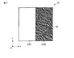
画像表示体22が含んでいる複数の画素PEの各々は、図3及び図5乃至図8に示すように、第1サブ画素SPE1と第2サブ画素SPE2とを含んでいる。これら図には、一例として、これらサブ画素SPE1及びSPE2が、X方向に互いに隣接している場合を描いている。X方向に隣接した画素PE間の境界は、散乱構造形成層223について上述した第1及び第2部分の境界に対応している。
Each of the plurality of pixels PE included in the
図3に示す画素PEでは、第1サブ画素SPE1は、特定の照明条件のもとで、指向性を有している散乱光を射出する複数の第1溝G1からなる。また、この画素PEでは、第2サブ画素SPE2は、上記の照明条件のもとで、指向性を有している散乱光を第1サブ画素SPE1とは異なる方向に射出する複数の第2溝G2からなる。 In the pixel PE shown in FIG. 3, the first sub-pixel SPE1 includes a plurality of first grooves G1 that emit scattered light having directivity under a specific illumination condition. Further, in this pixel PE, the second sub-pixel SPE2 has a plurality of second grooves for emitting scattered light having directivity in a direction different from that of the first sub-pixel SPE1 under the above illumination conditions. Consists of G2.
図5に示す画素PEでは、第1サブ画素SPE1は、複数の第1溝G1を備えていない。他方、この画素PEでは、第2サブ画素SPE2は、複数の第2溝G2からなる。図6(a)乃至(c)に示す画素PEでは、第1サブ画素SPE1は、複数の第1溝G1を備えていない。他方、これら画素PEでは、第2サブ画素SPE2は、複数の第2溝G2を部分的に備えている。即ち、これら画素PEでは、第2サブ画素SPE2は、複数の第2溝G2からなる領域と、複数の第2溝G2を備えていない他の領域とを含んでいる。 In the pixel PE shown in FIG. 5, the first sub-pixel SPE1 does not include a plurality of first grooves G1. On the other hand, in the pixel PE, the second sub-pixel SPE2 includes a plurality of second grooves G2. In the pixel PE shown in FIGS. 6A to 6C, the first sub-pixel SPE1 does not include a plurality of first grooves G1. On the other hand, in these pixels PE, the second sub-pixel SPE2 partially includes a plurality of second grooves G2. That is, in these pixels PE, the second sub-pixel SPE2 includes a region composed of a plurality of second grooves G2 and another region that does not include the plurality of second grooves G2.
図7に示す画素PEでは、第1サブ画素SPE1は、複数の第1溝G1からなる。他方、この画素PEでは、第2サブ画素SPE2は、複数の第2溝G2を備えていない。図8(a)乃至(c)に示す画素PEでは、第1サブ画素SPE1は、複数の第1溝G1を部分的に備えている。即ち、これら画素PEでは、第1サブ画素SPE1は、複数の第1溝G1からなる領域と、複数の第2溝G2を備えていない他の領域とを含んでいる。他方、これら画素PEでは、第2サブ画素SPE2は、複数の第2溝G2を備えていない。 In the pixel PE shown in FIG. 7, the first sub-pixel SPE1 includes a plurality of first grooves G1. On the other hand, in this pixel PE, the second sub-pixel SPE2 does not include a plurality of second grooves G2. In the pixel PE shown in FIGS. 8A to 8C, the first sub-pixel SPE1 partially includes a plurality of first grooves G1. That is, in these pixels PE, the first sub-pixel SPE1 includes a region composed of a plurality of first grooves G1 and another region that does not include the plurality of second grooves G2. On the other hand, in these pixels PE, the second sub-pixel SPE2 does not include a plurality of second grooves G2.
図3及び図5乃至図8に例示したように、第1サブ画素SP1は、複数の第1溝G1からなるか、これら溝G1を部分的に備えているか、又は、これら溝G1を備えていない。また、第2サブ画素SP2は、複数の第2溝G2からなるか、これら溝G2を部分的に備えているか、又は、これら溝G2を備えていない。そして、画素PEの各々は、これら第1サブ画素SPE1と第2サブ画素SPE2との任意の組み合わせを含んでいる。 As illustrated in FIGS. 3 and 5 to 8, the first sub-pixel SP <b> 1 includes a plurality of first grooves G <b> 1, partially includes these grooves G <b> 1, or includes these grooves G <b> 1. Absent. In addition, the second sub-pixel SP2 includes a plurality of second grooves G2, partially includes these grooves G2, or does not include these grooves G2. Each of the pixels PE includes any combination of the first subpixel SPE1 and the second subpixel SPE2.
第1サブ画素SPE1は、特定の照明条件のもとで第1視差画像を表示する第1要素領域を構成している。この第1視差画像は、例えば、観察者の右眼に視認させるための画像である。 The first sub-pixel SPE1 constitutes a first element region that displays a first parallax image under a specific illumination condition. This first parallax image is, for example, an image that is visually recognized by the right eye of the observer.
第2サブ画素SPE2は、特定の照明条件のもとで第2視差画像を表示する第2要素領域を構成している。この第2視差画像は、例えば、観察者の左眼に視認させるための画像である。 The second sub-pixel SPE2 constitutes a second element region that displays the second parallax image under a specific illumination condition. This second parallax image is, for example, an image that is visually recognized by the left eye of the observer.
このように、画像表示体22は、特定の照明条件のもとで第1視差画像を表示する第1要素領域と、この照明条件のもとで第2視差画像を表示する第2要素領域とを含んでいる。それゆえ、この画像表示体22は、特定の照明条件のもとで立体画像を表示する。
As described above, the
観察者が立体画像を知覚する条件のもとで、第1及び第2要素領域の各々が射出する散乱光は、観察者の左右の眼を結ぶ直線に平行な第1面内で発散する散乱光である。この散乱光は、回折格子などから射出される非発散性の回折光と比較して、視認可能な観察範囲がより広い。それゆえ、この画像表示体22では、観察条件の変動による立体画像の視認性の変化が生じ難い。即ち、この画像表示体22は、画質が高い立体画像を表示する。
Scattered light emitted from each of the first and second element regions is scattered in a first plane parallel to a straight line connecting the left and right eyes of the observer under the condition that the observer perceives a stereoscopic image. Light. This scattered light has a wider viewing range than non-divergent diffracted light emitted from a diffraction grating or the like. Therefore, in the
また、上述した通り、表紙本体21は、典型的には紙片である。即ち、図1に示す物品100では、典型的には、基材として紙を用いる。紙は、典型的には、粗面を有している。それゆえ、画像表示体22は、典型的には、基材の粗面上に貼り付けられている。
Further, as described above, the cover
本発明者らは、回折格子などを用いた非発散性の回折光に基づいて立体画像を表示する画像表示体を粗面に貼り付けると、局所的な濃淡や色変化を生じ、立体画像の画質に悪影響を生じる場合があることを見出している。これに対し、画像表示体22は、散乱構造を備えているため、非発散性の回折光に基づいて立体画像を表示する画像表示体と比較して、粗面に貼り付けられることに起因した表示への悪影響を被り難い。従って、物品100は、基材の粗面の質感等を維持しつつ、画質の高い立体画像を表示することができる。
When the image display body that displays a stereoscopic image based on non-divergent diffracted light using a diffraction grating or the like is attached to a rough surface, the present inventors produce local shading and color change, and the stereoscopic image It has been found that image quality may be adversely affected. On the other hand, since the
なお、ここで「粗面」とは、日本工業規格JIS B0601:2001(国際規格ISO 4287:1997)に準拠して測定された算術平均粗さRaが1乃至10μmの範囲内にある面を意味することとする。 Here, the “rough surface” means a surface having an arithmetic average roughness Ra measured in accordance with Japanese Industrial Standard JIS B0601: 2001 (international standard ISO 4287: 1997) in the range of 1 to 10 μm. I decided to.
紙などの粗面は、典型的には、大きな周期の凹凸構造、即ちうねりを有している。例えば、算術平均粗さRaが約2.0μmである紙の表面を調べたところ、このうねりの主成分は0.1乃至1.0mm程度の周期を有しており、その凹凸の深さは0.01乃至0.5mm程度であった。この深さは、例えば、非発散性の回折光に基づいて立体画像を表示する画像表示体に用いられる回折格子の高さ又は深さと比較してより大きい。従って、このような回折格子を用いた画像表示体は、粗面に貼り付けられることに起因した表示への悪影響を比較的被り易い。 A rough surface such as paper typically has a concavo-convex structure having a large period, that is, undulation. For example, when the surface of the paper whose arithmetic average roughness Ra is about 2.0 μm is examined, the main component of this undulation has a period of about 0.1 to 1.0 mm, and the depth of the unevenness is It was about 0.01 to 0.5 mm. This depth is larger than, for example, the height or depth of a diffraction grating used in an image display body that displays a stereoscopic image based on non-divergent diffracted light. Therefore, an image display using such a diffraction grating is relatively susceptible to the adverse effect on the display caused by being attached to a rough surface.
第1及び第2要素領域の各々が射出する散乱光は、例えば、上記第1面内において2乃至7°の角度範囲で発散する散乱光である。
観察者の左右の眼を結ぶ線分の長さが65mmであり、画像表示体22の表示面と上記第1面との距離が500mmであるとする。この場合、観察者の左右の眼の視線が為す角度は、約7.4゜である。それゆえ、上記の角度範囲を7゜以下とすると、第1及び第2要素領域の各々が射出する散乱光は、左右の眼に同時に入射することはない。従って、こうすると、一方の眼によって視認させるべき視差画像が他方の眼によって視認させるべき視差画像のノイズとなるのを防止できる。即ち、こうすると、立体画像の画質を向上させることができる。
The scattered light emitted from each of the first and second element regions is, for example, scattered light that diverges in an angle range of 2 to 7 ° within the first surface.
It is assumed that the length of a line segment connecting the left and right eyes of the observer is 65 mm, and the distance between the display surface of the
他方、観察者の左右の眼の各々の入射瞳径が5mmであり、画像表示体22の表示面と上記第1面との距離が500mmであるとする。この場合、左右の眼の各々の見込み角は0.6゜である。それゆえ、上記の角度範囲を2゜以上とすると、この見込み角の2倍以上の視域を確保することが可能となり、安定した画像表示を行うことができる。また、こうすると、視差画像の数を過度に多くする必要がなくなる。即ち、こうすると、画像表示体22の作製が容易となると共に、視差画像の解像度の低下に起因した画質の低下を抑制できる。
On the other hand, it is assumed that the entrance pupil diameter of each of the left and right eyes of the observer is 5 mm, and the distance between the display surface of the
また、第1及び第2要素領域の各々が射出する散乱光は、観察者が立体画像を知覚する条件のもとで、観察者の左右の眼を結ぶ直線に垂直な第2面内で更に発散する散乱光であってもよい。この場合、上記第2面内で観察角度を変化させた場合であっても、幅広い範囲で立体画像が観察できる。即ち、この場合、観察条件の変動による立体画像の視認性の変化を更に生じ難くすることができる。 Further, the scattered light emitted from each of the first and second element regions is further transmitted in a second plane perpendicular to a straight line connecting the left and right eyes of the observer under the condition that the observer perceives a stereoscopic image. It may be scattered light that diverges. In this case, even when the observation angle is changed in the second surface, a stereoscopic image can be observed in a wide range. That is, in this case, the change in the visibility of the stereoscopic image due to the change in the viewing condition can be further prevented.
第1及び第2要素領域の各々が射出する散乱光が上記第2面内で更に発散する散乱光である場合、上記の第2面内における散乱光の角度範囲は、例えば、10゜以上とする。この角度範囲を10゜未満とすると、後述する計算機ホログラムなどを用いて回折光に基づいた散乱光を射出させる場合に、安定した白色表示を行うことが困難となる場合がある。 When the scattered light emitted from each of the first and second element regions is scattered light that further diverges in the second surface, the angular range of the scattered light in the second surface is, for example, 10 ° or more. To do. If this angle range is less than 10 °, it may be difficult to perform stable white display when scattered light based on diffracted light is emitted using a computer generated hologram or the like to be described later.
なお、「散乱光の角度範囲」は、以下のようにして定める。即ち、ある面内において、当該散乱光の最大強度の10%以上の強度を有した散乱光が射出される範囲を、上記の角度範囲とする。 The “angle range of scattered light” is determined as follows. That is, a range in which scattered light having an intensity of 10% or more of the maximum intensity of the scattered light is emitted within a certain plane is defined as the above-described angle range.
第1及び第2要素領域の各々は、上述した通り、散乱構造としての複数の溝を備えている。観察者が立体画像を知覚する条件のもとで、観察者の左右の眼を結ぶ直線に垂直な面と表示面との交線に平行な方向を縦方向とする。この縦方向は、例えば、図2乃至図8におけるY方向に平行である。 Each of the first and second element regions includes a plurality of grooves as a scattering structure as described above. Under the condition that the observer perceives a stereoscopic image, the direction parallel to the line of intersection between the surface perpendicular to the straight line connecting the left and right eyes of the observer and the display surface is defined as the vertical direction. This vertical direction is, for example, parallel to the Y direction in FIGS.
このとき、第1及び第2要素領域の各々において、複数の溝の上記縦方向における空間周波数は、典型的には、ゼロより大きくする。こうすると、正反射光などの非散乱光が観察可能となる条件と、視差画像を表示する散乱光が観察可能となる条件とを互いに分離することができる。即ち、こうすると、散乱光に基づいた立体画像を観察する際に、非散乱光による悪影響を抑制することが可能となる。従って、こうすると、画像表示体22に、高品位な立体画像を表示させることが可能となる。
At this time, in each of the first and second element regions, the spatial frequency in the vertical direction of the plurality of grooves is typically made larger than zero. By doing this, it is possible to separate a condition that enables observation of non-scattered light such as specularly reflected light and a condition that enables observation of scattered light that displays a parallax image. That is, in this way, when observing a stereoscopic image based on scattered light, it is possible to suppress an adverse effect due to non-scattered light. Therefore, this makes it possible to display a high-quality stereoscopic image on the
複数の溝の上記縦方向における空間周波数は、例えば、500mm-1以上とする。可視光の最短波長を400nmとすると、複数の溝が射出するこの波長の散乱光の射出方向とこの波長の正反射光の射出方向とが為す分離角は11.5゜である。従って、このような構成を採用すると、可視光波長の全域に亘って、上記の分離角を10゜以上とすることができる。それゆえ、こうすると、画像表示体22は、更に高品位な立体画像を表示する。
The spatial frequency in the vertical direction of the plurality of grooves is, for example, 500 mm −1 or more. Assuming that the shortest wavelength of visible light is 400 nm, the separation angle formed by the emission direction of the scattered light having this wavelength emitted by the plurality of grooves and the emission direction of the regular reflection light having this wavelength is 11.5 °. Therefore, when such a configuration is adopted, the separation angle can be set to 10 ° or more over the entire visible light wavelength range. Therefore, in this way, the
なお、ここで「散乱光の射出方向」とは、散乱光を構成する成分のうちその強度が最大であるものの射出方向を意味している。 Here, “the direction of emission of scattered light” means the direction of emission of the component constituting the scattered light having the maximum intensity.
第1及び第2要素領域の各々が備えている複数の溝の少なくとも一方は、例えば、計算機ホログラム(Computer Generated Hologram)の手法で設計してもよい。即ち、第1及び第2要素領域の各々は、計算機ホログラムとしての複数の溝を備えていてもよい。こうすると、これら第1及び第2要素領域の各々に、予め設定した所望の角度範囲に散乱光を射出させることができる。また、このような構成を採用すると、立体画像の表示に寄与しないか又は立体画像の表示に悪影響を与えるノイズ光の射出を抑制することができる。 At least one of the plurality of grooves provided in each of the first and second element regions may be designed by, for example, a computer generated hologram method. That is, each of the first and second element regions may include a plurality of grooves as a computer generated hologram. In this case, the scattered light can be emitted to each of the first and second element regions in a predetermined desired angle range. In addition, when such a configuration is adopted, it is possible to suppress emission of noise light that does not contribute to the display of the stereoscopic image or adversely affects the display of the stereoscopic image.
計算機ホログラムとしては、例えば、キノフォーム(Kinoform)を用いる。こうすると、共役像の表示を抑制できるため、画像表示体22に、高品位な立体画像を表示させることができる。或いは、計算機ホログラムとして、バイナリ型計算機ホログラムを用いてもよい。この場合であっても、再生像と共役像とが同時に観察されないような設計とすることにより、画像表示体22に、高品位な立体画像を表示させることができる。
As the computer generated hologram, for example, a kinoform is used. In this way, since the display of the conjugate image can be suppressed, a high-quality stereoscopic image can be displayed on the
計算機ホログラムを用いた場合、光の回折により波長分散が生じる。以下、回折格子を例にして、微細周期構造による回折現象について説明する。 When a computer generated hologram is used, wavelength dispersion occurs due to light diffraction. Hereinafter, the diffraction phenomenon due to the fine periodic structure will be described using a diffraction grating as an example.
照明光の正反射角度をα、回折格子によって回折した1次回折光の射出角度をβ、光の波長をλ、回折格子のピッチ(空間周波数の逆数)をdとすると、下式が成り立つ。 If the regular reflection angle of the illumination light is α, the emission angle of the first-order diffracted light diffracted by the diffraction grating is β, the wavelength of the light is λ, and the pitch of the diffraction grating (reciprocal of the spatial frequency) is d, the following equation holds.
λ=d{sin (α)−sin (β)}
即ち、白色光が特定の角度|α|でピッチがdである回折格子に入射すると、1次回折光は、波長λ毎に異なる射出角度βで射出する。
λ = d {sin (α) −sin (β)}
That is, when white light is incident on a diffraction grating having a specific angle | α | and a pitch d, the first-order diffracted light is emitted at a different emission angle β for each wavelength λ.
この回折格子に白色光を照明した場合、この回折格子を特定の観察方向から観察すると、可視波長の中の特定の波長が観察され、特定の色が認識できる。それゆえ、白色光を射出する光源と回折格子との位置を固定して、その観察角度を次第に変化させると、回折格子は、赤から青の範囲で虹色に変化して見える。 When this diffraction grating is illuminated with white light, when the diffraction grating is observed from a specific observation direction, a specific wavelength among visible wavelengths is observed, and a specific color can be recognized. Therefore, when the position of the light source that emits white light and the diffraction grating is fixed and the observation angle is gradually changed, the diffraction grating appears to change from rainbow to red in the range from red to blue.
計算機ホログラムは、ランダムな位相を有した回折構造を有している。このような構成を採用すると、所望の角度範囲に、種々の波長λを有した回折光が混合されてなる光を射出させることができる。即ち、計算機ホログラムを用いると、例えば、特定の角度範囲に、白色光を射出させることが可能となる。 The computer generated hologram has a diffractive structure having a random phase. By adopting such a configuration, it is possible to emit light in which diffracted light having various wavelengths λ is mixed in a desired angle range. That is, when a computer generated hologram is used, for example, white light can be emitted in a specific angle range.
第1及び第2要素領域の各々が備えている複数の溝が計算機ホログラムである場合、この計算機ホログラムが射出する散乱光は、典型的には、上記第2面内で更に発散する散乱光である。この場合、上記第2面内における散乱光の角度範囲は、例えば、10゜以上とする。こうすると、安定した白色表示を行うことが可能となる。他方、上記第2面内における散乱光の角度範囲を9゜以下とすると、通常の室内光源下において、回折光に起因した色づきが観察されることがある。即ち、こうすると、白色表示に悪影響を生ずることがある。 When the plurality of grooves provided in each of the first and second element regions is a computer generated hologram, the scattered light emitted from the computer generated hologram is typically scattered light further diverging in the second surface. is there. In this case, the angle range of the scattered light in the second surface is, for example, 10 ° or more. In this way, stable white display can be performed. On the other hand, if the angle range of scattered light in the second surface is 9 ° or less, coloring caused by diffracted light may be observed under a normal indoor light source. That is, this may adversely affect the white display.
上では、複数の画素PEの各々が2つのサブ画素SPE1及びSPE2からなる場合について説明したが、画素PEの各々に含まれるサブ画素の数は、3以上であってもよい。 Although the case where each of the plurality of pixels PE includes two subpixels SPE1 and SPE2 has been described above, the number of subpixels included in each of the pixels PE may be three or more.
図9は、図3に示す物品の一部の一変形例を示す平面図である。図9には、図3に示す画素の一変形例に係る画素PEを描いている。 FIG. 9 is a plan view showing a modification of a part of the article shown in FIG. FIG. 9 shows a pixel PE according to a modification of the pixel shown in FIG.
図9に示す画素PEは、第1サブ画素SPE1と、第2サブ画素SPE2と、第3サブ画素SPE3と、第4サブ画素SPE4とを含んでいる。図9には、一例として、これらサブ画素SPE1乃至SPE4が、X方向に互いに隣接している場合を描いている。 The pixel PE shown in FIG. 9 includes a first sub-pixel SPE1, a second sub-pixel SPE2, a third sub-pixel SPE3, and a fourth sub-pixel SPE4. In FIG. 9, as an example, a case where these sub-pixels SPE1 to SPE4 are adjacent to each other in the X direction is illustrated.
これらサブ画素SPE1乃至SPE4の各々は、特定の照明条件のもとで、指向性を有している散乱光を互いに異なった方向に射出する散乱構造を備えている。サブ画素SPE1乃至SPE4のうちこの散乱構造を備えているものは、それぞれ、特定の照明条件のもとで第1乃至第4視差画像を表示する第1乃至第4要素領域を構成している。 Each of the sub-pixels SPE1 to SPE4 includes a scattering structure that emits directional scattered light in different directions under a specific illumination condition. Of the sub-pixels SPE1 to SPE4, those having this scattering structure constitute first to fourth element regions for displaying first to fourth parallax images under specific illumination conditions, respectively.
ここで、画像表示体22の観察位置を、図9に示すX方向に沿って次第に変化させていった場合を考える。この場合、第1に、第4視差画像が観察者の左眼に視認されると共に第3視差画像が観察者の右眼に視認されることにより、立体画像が観察できる。第2に、第3視差画像が観察者の左眼に視認されると共に第2視差画像が観察者の右眼に視認されることにより、立体画像が観察できる。第3に、第2視差画像が観察者の左眼に視認されると共に第1視差画像が観察者の右眼に視認されることにより、立体画像が観察できる。このように、図9に例示した構成を採用した場合、画像表示体22は、より広い角度範囲で視認可能な立体画像を表示することができる。
Here, a case is considered where the observation position of the
これら第1乃至第4要素領域の各々は、典型的には、上記第1面内における角度範囲が部分的に重なり合うように、散乱光を射出する。こうすると、観察角度を連続的に変化させた場合に、左右の眼に、各視差画像を連続的に視認させることができる。即ち、こうすると、観察角度を連続的に変化させた場合に、立体画像が突然視認できなくなる可能性を抑制できる。従って、このような構成を採用すると、画像のチラつきが特に少ない立体画像を表示することが可能となる。 Each of the first to fourth element regions typically emits scattered light so that the angular ranges in the first surface partially overlap. In this way, when the observation angle is continuously changed, each parallax image can be visually recognized by the left and right eyes. That is, in this way, when the observation angle is continuously changed, the possibility that the stereoscopic image cannot be suddenly visually recognized can be suppressed. Therefore, when such a configuration is adopted, it is possible to display a stereoscopic image with particularly little flickering.
図10は、散乱光の強度分布の関係を概略的に示す図である。図10には、要素領域の各々から射出される散乱光の特定の面内における強度分布を概略的に描いている。図10には、一例として、第2要素領域が射出する散乱光の強度分布C2と、第1要素領域が射出する散乱光の強度分布C1とを描いている。 FIG. 10 is a diagram schematically showing the relationship of the intensity distribution of scattered light. FIG. 10 schematically shows an intensity distribution in a specific plane of scattered light emitted from each element region. FIG. 10 illustrates, as an example, an intensity distribution C2 of scattered light emitted from the second element region and an intensity distribution C1 of scattered light emitted from the first element region.
なお、これら強度分布を測定する「特定の面」は、観察者の左右の眼を結ぶ直線に平行な第1面のうち、画像表示体22の表示面に平行であり且つこの表示面からの距離が500mmの面であるとする。以下、この「特定の面」を「第3面」と呼ぶ。
The “specific surface” for measuring the intensity distribution is parallel to the display surface of the
強度分布C2及びC1の交点ISにおける各散乱光の強度は、典型的には、当該散乱光の最大強度の10%以上である。即ち、第1及び第2要素領域の各々は、典型的には、第3面内における角度範囲が部分的に重なり合うように、散乱光を射出する。また、強度分布C2及びC1の交点ISにおける各散乱光の強度は、典型的には、当該散乱光の最大強度の50%以下とする。この強度が過度に大きいと、各要素領域が射出する散乱光の角度範囲の重複が大きくなり、画像のぼけが生じることがある。即ち、こうすると、コントラストの低下による画質の低下を生じることがある。 The intensity of each scattered light at the intersection IS of the intensity distributions C2 and C1 is typically 10% or more of the maximum intensity of the scattered light. That is, each of the first and second element regions typically emits scattered light so that the angular ranges in the third plane partially overlap. The intensity of each scattered light at the intersection IS of the intensity distributions C2 and C1 is typically 50% or less of the maximum intensity of the scattered light. If this intensity is excessively large, the overlapping of the angular range of the scattered light emitted from each element region becomes large, and the image may be blurred. In other words, this may cause a reduction in image quality due to a decrease in contrast.
なお、ここでは、画素PEの各々が4つのサブ画素SPE1乃至SPE4を含んでいる場合について説明したが、画素PEの各々が含んだサブ画素の数が3以上であれば、上述した効果を達成することができる。 Here, the case where each of the pixels PE includes four sub-pixels SPE1 to SPE4 has been described. However, if the number of sub-pixels included in each of the pixels PE is three or more, the above-described effect is achieved. can do.
図2乃至図9を参照しながら説明した画素PEでは、複数のサブ画素は、X方向に互いに隣り合っている。しかしながら、上述した通り、画素PEは小さな寸法を有しており、典型的には、肉眼で観察した場合にそれら画素PEを互いから区別することはできない。従って、画素PE内におけるサブ画素の配置は、任意である。例えば、これら複数のサブ画素は、Y方向に隣り合っていてもよい。 In the pixel PE described with reference to FIGS. 2 to 9, the plurality of sub-pixels are adjacent to each other in the X direction. However, as described above, the pixels PE have small dimensions and typically cannot be distinguished from each other when viewed with the naked eye. Therefore, the arrangement of the sub-pixels in the pixel PE is arbitrary. For example, the plurality of sub-pixels may be adjacent to each other in the Y direction.
画素PEが備えている散乱構造には、種々の変形が可能である。
図11は、図3に示す物品の一部に採用可能な構造の例を示す断面図である。図12は、図3に示す物品の一部に採用可能な構造の他の例を示す平面図である。
Various modifications can be made to the scattering structure of the pixel PE.
FIG. 11 is a cross-sectional view showing an example of a structure that can be adopted for a part of the article shown in FIG. FIG. 12 is a plan view showing another example of a structure that can be adopted for a part of the article shown in FIG.
図11の(a)及び(b)には、散乱構造形成層223と反射層224との積層構造を描いている。図11(b)に示す構造は、図11(a)に示す構造と比較して、複数の溝の深さ又は高さがより小さい。従って、図11(b)に示す構造は、図11(a)に示す構造と比較して、より暗い像の表示を可能とする。それゆえ、これら構造を組み合わせて用いることにより、階調表示を行うことができる。また、深さ又は高さが互いに異なった複数の溝の分布を解析することは、極めて困難である。それゆえ、こうすると、改竄又は偽造が特に困難な画像表示体22を形成することができる。
11A and 11B illustrate a laminated structure of the scattering
図12の(a)及び(b)には、サブ画素における複数の溝の分布の例を示している。図12(a)に示すサブ画素では、サブ画素に占める複数の溝の占有面積は100%である。他方、図12(b)に示すサブ画素では、サブ画素に占める複数の溝の占有面積は50%である。このように、サブ画素に占める複数の溝の占有面積を異ならせることにより、表示すべき画像の輝度を容易に調整することができる。また、これら構造を組み合わせて用いることにより、階調表示を行うことができる。加えて、この場合、複数の溝の占有面積の大きさの差異のみに基づいて、階調表示を行うことができる。即ち、この場合、階調表示が可能な画像表示体22を比較的簡便に作製することができる。
FIGS. 12A and 12B show examples of the distribution of a plurality of grooves in the sub-pixel. In the subpixel shown in FIG. 12A, the occupied area of the plurality of grooves in the subpixel is 100%. On the other hand, in the subpixel shown in FIG. 12B, the area occupied by the plurality of grooves in the subpixel is 50%. In this way, the luminance of the image to be displayed can be easily adjusted by making the occupied areas of the plurality of grooves occupying the sub-pixels different. Moreover, gradation display can be performed by using a combination of these structures. In addition, in this case, gradation display can be performed based only on the difference in size of the occupied areas of the plurality of grooves. That is, in this case, the
図13は、図3に示す物品の一部に採用可能な構造の他の例を示す平面図である。図14は、図13に示す構造をフーリエ変換して得られる像を示す平面図である。図13及び図14から分かるように、図13に示す複数の溝は、照明光を照射すると、図13に示すX方向に垂直な方向に、指向性を有している散乱光を射出することができる。従って、図13に示すような構造も、上記の散乱構造として採用することができる。 FIG. 13 is a plan view showing another example of a structure that can be adopted for a part of the article shown in FIG. FIG. 14 is a plan view showing an image obtained by Fourier transform of the structure shown in FIG. As can be seen from FIGS. 13 and 14, the plurality of grooves shown in FIG. 13 emits scattered light having directivity in the direction perpendicular to the X direction shown in FIG. 13 when irradiated with illumination light. Can do. Therefore, a structure as shown in FIG. 13 can also be adopted as the scattering structure.
上では、散乱構造として複数の溝を用いる場合について説明したが、この散乱構造は、他の構成を有していてもよい。例えば、この散乱構造として、複数の筋を用いてもよい。或いは、散乱構造として、溝又は筋以外の複数の凹部又は凸部を用いてもよい。或いは、散乱構造として、複数の凹部又は凸部以外の構成を採用してもよい。 Although the case where a plurality of grooves are used as the scattering structure has been described above, the scattering structure may have other configurations. For example, a plurality of streaks may be used as the scattering structure. Or you may use several recessed part or convex part other than a groove | channel or a line | wire as a scattering structure. Alternatively, a configuration other than a plurality of concave portions or convex portions may be adopted as the scattering structure.
図15及び図16は、図3に示す物品の一部に採用可能な構造の他の例を示す斜視図である。
図15及び図16に示す構造は、複数の凸部を備えている。これら複数の凸部の各々は、一方向に延びた形状を有している。また、これら複数の凸部は、典型的には、長手方向が揃っている。従って、これら複数の凸部は、指向性を有している散乱光の射出を可能とする。
15 and 16 are perspective views showing other examples of structures that can be employed in a part of the article shown in FIG.
The structure shown in FIGS. 15 and 16 includes a plurality of convex portions. Each of the plurality of convex portions has a shape extending in one direction. The plurality of convex portions are typically aligned in the longitudinal direction. Therefore, these plurality of convex portions enable emission of scattered light having directivity.
図15に示す構造は、基準面SF上に、直方体形状の複数の凸部P1を含んでいる。複数の凸部P1の長辺の長さは、例えば、その短辺の長さの1倍より大きく且つ5倍より小さい。これら複数の凸部P1の長辺は、X方向に平行である。即ち、これら複数の凸部P1は、X方向に異方性を有している。従って、これら複数の凸部P1は、特定の照明条件において、X方向に垂直な方向に、指向性を有している散乱光を射出することができる。 The structure shown in FIG. 15 includes a plurality of rectangular parallelepiped convex portions P1 on the reference plane SF. The length of the long side of the plurality of convex portions P1 is, for example, greater than 1 time and less than 5 times the length of the short side. The long sides of the plurality of convex portions P1 are parallel to the X direction. That is, the plurality of convex portions P1 are anisotropic in the X direction. Therefore, the plurality of convex portions P1 can emit scattered light having directivity in a direction perpendicular to the X direction under a specific illumination condition.
図16に示す構造は、基準面SF上に、楕円柱形状の複数の凸部P2を含んでいる。複数の凸部P2の長軸の長さは、例えば、その短軸の長さの1倍より大きく且つ5倍より小さい。これら複数の凸部P2の長軸は、X方向に平行である。即ち、これら複数の凸部P2は、X方向に異方性を有している。従って、これら複数の凸部P2は、特定の照明条件において、X方向に垂直な方向に、指向性を有している散乱光を射出することができる。 The structure shown in FIG. 16 includes a plurality of convex portions P2 having an elliptic cylinder shape on the reference plane SF. The length of the major axis of the plurality of convex portions P2 is, for example, greater than one time and less than five times the length of the minor axis. The major axes of the plurality of convex portions P2 are parallel to the X direction. That is, the plurality of convex portions P2 have anisotropy in the X direction. Therefore, the plurality of convex portions P2 can emit scattered light having directivity in a direction perpendicular to the X direction under a specific illumination condition.
次に、図17乃至図19を参照しながら、物品100の製造方法を説明する。
図17は、図1に示す物品の製造に使用可能なブランク媒体の一例を概略的に示す平面図である。図18は、図17に示すブランク媒体の一部を拡大して示す断面図である。
Next, a method for manufacturing the
FIG. 17 is a plan view schematically showing an example of a blank medium that can be used for manufacturing the article shown in FIG. 18 is an enlarged cross-sectional view of a part of the blank medium shown in FIG.
図18に示すように、ブランク媒体200は、保護層227と散乱構造形成層223と反射層224とを含んでいる。これら層としては、例えば、先に図4を参照しながら説明したのと同様の構成を採用する。
As shown in FIG. 18, the
図17に示すように、ブランク媒体200は、互いに交差するX及びY方向に配列した複数の画素PEを含んでいる。これら複数の画素PEの各々は、サブ画素SPE1及びSPE2を含んでいる。これらサブ画素SPE1及びSPE2の各々は、特定の照明条件のもとで、指向性を有している散乱光を互いに異なる方向に射出する。これら画素PE並びにサブ画素SPE1及びSPE2としては、例えば、先に図3を参照しながら説明したのと同様の構成を採用する。
As shown in FIG. 17, the
物品100の製造においては、例えば、まず、複数の撮像装置を用いて、互いに異なった方向から、人物の顔を同時に撮影する。この顔画像は、必要に応じて画像処理する。
In manufacturing the
次に、複数の第1サブ画素SPE1の一部に対して、レーザビームを照射する。これにより、複数の第1サブ画素SPE1の一部について、散乱構造の一部又は全部を変形又は破壊する。このようにして、複数の第1サブ画素SPE1の一部について、第1サブ画素SPE1が射出する散乱光の散乱効率をゼロとするか又は低減する。これにより、特定の照明条件のもとで第1視差画像を表示する第1要素領域を形成する。 Next, a laser beam is irradiated to some of the plurality of first sub-pixels SPE1. Accordingly, a part or all of the scattering structure is deformed or destroyed with respect to some of the plurality of first sub-pixels SPE1. In this way, the scattering efficiency of the scattered light emitted from the first subpixel SPE1 is set to zero or reduced for some of the plurality of first subpixels SPE1. Thereby, a first element region for displaying the first parallax image under a specific illumination condition is formed.
加えて、複数の第2サブ画素SPE2の一部に対しても、レーザビームを照射する。これにより、複数の第2サブ画素SPE2の一部について、散乱構造の一部又は全部を変形又は破壊する。このようにして、複数の第2サブ画素SPE2の一部について、第2サブ画素SPE2が射出する散乱光の散乱効率をゼロとするか又は低減する。これにより、特定の照明条件のもとで第2視差画像を表示する第2要素領域を形成する。 In addition, a laser beam is also applied to some of the plurality of second sub-pixels SPE2. Thereby, a part or all of the scattering structure is deformed or destroyed with respect to a part of the plurality of second sub-pixels SPE2. In this way, the scattering efficiency of the scattered light emitted by the second subpixel SPE2 is set to zero or reduced for a part of the plurality of second subpixels SPE2. Thereby, the 2nd element field which displays the 2nd parallax picture under specific lighting conditions is formed.
次いで、得られた構造を、接着層225を介して、表紙本体21に貼り付ける。その後、必要な工程を適宜実施する。このようにして、物品100を得る。
Next, the obtained structure is attached to the
この方法によると、オンデマンドで、複数の視差画像に基づいた立体画像を記録することができる。従って、この方法は、個別の像を少量ずつ記録する必要がある個人認証媒体等の用途において、特に有用である。また、散乱構造を変形又は破壊する部分の面積を複数のサブ画素間で互いに異ならせることにより、立体画像に階調を付与することもできる。こうすると、更に高品位な立体画像が得られる。 According to this method, a stereoscopic image based on a plurality of parallax images can be recorded on demand. Therefore, this method is particularly useful in applications such as personal authentication media that require individual images to be recorded in small amounts. In addition, gradation can be given to a stereoscopic image by making the area of a portion that deforms or destroys the scattering structure different among a plurality of subpixels. In this way, a higher quality stereoscopic image can be obtained.
なお、上では、散乱光の散乱効率をゼロとするか又は低減する工程をレーザビームを用いて行う方法について説明したが、この工程は、レーザビーム以外のエネルギービームを用いて行ってもよい。例えば、この工程は、電子ビームなどの荷電粒子ビームを照射することによって行ってもよい。電子ビーム描画装置によると、レーザと比較して、より小さなビーム径を達成できる。従って、例えばサブ画素の寸法が小さい場合、電子ビーム照射を利用すると、レーザビームを利用した場合と比較して、より高い画質を達成できる。 In the above description, the method of using the laser beam to perform the step of reducing or reducing the scattering efficiency of the scattered light has been described. However, this step may be performed using an energy beam other than the laser beam. For example, this step may be performed by irradiating a charged particle beam such as an electron beam. According to the electron beam drawing apparatus, a smaller beam diameter can be achieved as compared with the laser. Therefore, for example, when the size of the sub-pixel is small, higher image quality can be achieved when electron beam irradiation is used compared to when a laser beam is used.
散乱光の散乱効率をゼロとするか又は低減する工程は、他の方法によって行ってもよい。例えば、この工程は、サーマルヘッドなどの加熱及び/又は加圧手段を用いて散乱構造を変形又は破壊することにより行ってもよい。或いは、この工程は、インクジェット法などを用いて、散乱構造上に、散乱構造形成層223の材料を溶解可能な液を供給することにより行ってもよい。或いは、この工程は、インクジェット法などを用いて、散乱構造上に、散乱構造形成層223の材料と屈折率が同一であるか屈折率の差が小さい材料を供給することにより行ってもよい。或いは、この工程は、インクジェット法などを用いて、散乱構造上に、黒色インキなどの光吸収剤を供給することにより行ってもよい。
The step of reducing or reducing the scattering efficiency of the scattered light may be performed by other methods. For example, this step may be performed by deforming or destroying the scattering structure using heating and / or pressing means such as a thermal head. Alternatively, this step may be performed by supplying a liquid capable of dissolving the material of the scattering
図19は、図1に示す物品の製造に使用可能な転写箔の一例を概略的に示す平面図である。
図19に示す転写箔201は、ブランク媒体としての転写材層220a’と、これを剥離可能に支持した支持体221とを含んでいる。
FIG. 19 is a plan view schematically showing an example of a transfer foil that can be used for manufacturing the article shown in FIG.
A
支持体221は、例えば樹脂フィルム又はシートである。支持体221は、例えば、ポリエチレンテレフタレート(PET)などの耐熱性に優れた材料からなる。支持体221の転写材層220a’を支持している主面には、例えばフッ素樹脂又はシリコーン樹脂を含んだ離型層が設けられていてもよい。
The
転写材層220a’は、保護層227と散乱構造形成層223と反射層224とを含んでいる。保護層227と散乱構造形成層223と反射層224は、支持体221上にこの順に形成されている。これら層としては、例えば、先に図4を参照しながら説明したのと同様の構成を採用する。転写材層220a’の全体又は一部は、画像表示層220aの製造に利用する。
The
物品100の製造においては、まず、例えば先に述べたのと同様にして、顔画像を得る。
次に、表紙本体21に対し、転写材層220a’の一部を、サーマルヘッドなどの加熱及び/又は加圧手段を用いて転写する。具体的には、表紙本体21のうち上記の第1視差画像を表示させるべき位置に、複数の第1サブ画素の一部を転写すると共に、表紙本体21のうち上記の第2視差画像を表示させるべき位置に、複数の第2サブ画素の一部を転写する。なお、この転写は、反射層224上に接着層225を形成した後に行ってもよい。
In manufacturing the
Next, a part of the
このようにして、表紙本体21上に、画像表示層220aを形成する。その後、必要な工程を適宜実施する。このようにして、物品100を得る。
In this way, the
この方法によると、オンデマンドで、複数の視差画像に基づいた立体画像を記録することができる。従って、この方法は、個別の像を少量ずつ記録する必要がある個人認証媒体等の用途において、特に有用である。また、表紙本体21上に転写する部分の面積を複数のサブ画素間で互いに異ならせることにより、立体画像に階調を付与することもできる。こうすると、更に高品位な立体画像が得られる。
According to this method, a stereoscopic image based on a plurality of parallax images can be recorded on demand. Therefore, this method is particularly useful in applications such as personal authentication media that require individual images to be recorded in small amounts. Further, gradation can be imparted to the stereoscopic image by making the area of the portion transferred onto the cover
なお、上では、複数の画素PEを含んだ画像表示体22について説明したが、画像表示体22は、このような構成を有していなくてもよい。即ち、画像表示体22は、特定の照明条件のもとで、指向性を有している散乱光を互いに異なる方向に射出して各々が視差画像を表示する複数の要素領域を含んでいればよい。従って、画像表示体22は、例えば、これら複数の要素領域に対応した構造を備えた原版を準備し、この原版を用いて散乱構造形成層223を形成することによって製造してもよい。
Although the
以上、パスポートとしての物品100を例示したが、物品100について上述した技術は、他の物品に適用することも可能である。例えば、この技術は、査証及びIDカードなどの各種カードに適用することも可能である。或いは、この技術は、紙幣及び商品券などの有価証券に適用することも可能である。
The
画像表示体22を貼り付ける基材の材質は、天然の紙及び合成紙などの紙でなくてもよい。例えば、画像表示体22を貼り付ける基材の材質は、ポリエチレンテレフタレート樹脂(熱可塑性PET)、ポリ塩化ビニル樹脂、熱硬化性ポリエステル樹脂、ポリカーボネート樹脂、ポリメタクリル樹脂及びポリスチレン樹脂などの合成樹脂、ガラス、陶器及び磁器などのセラミックス、又は、単体金属及び合金などの金属材料であってもよい。
The material of the base material to which the
上では、物品としてパスポートなどの個人認証媒体を例示したが、物品100について上述した技術は、個人認証媒体以外の物品に適用することも可能である。即ち、上述した技術は、個人認証以外の目的で利用してもよい。例えば、この技術は、パッケージ用途に用いてもよい。
In the above, a personal authentication medium such as a passport is exemplified as the article. However, the technology described above for the
図20は、本発明の他の態様に係る物品を概略的に示す斜視図である。図20に示す物品300は、商品のパッケージである。この物品300には、上述した構成に基づいて立体画像の表示を可能とする画像表示体22が貼り付けられている。従って、例えば、画像表示体22にロゴマーク及び商品名などを立体画像として表示させることにより、消費者の注意を強く喚起することが可能となる。また、画像表示体22を用いると、物品300が紙などの粗面を含んでいる場合であっても、これに画質の高い立体画像を表示させることができる。
FIG. 20 is a perspective view schematically showing an article according to another aspect of the present invention. An
1…折り丁、2…表紙、11…紙片、12…印刷パターン、21…表紙本体、22…画像表示体、、100…物品、200…ブランク媒体、201…転写箔、220a…画像表示層、220a’…転写材層221…支持体層、223…散乱構造形成層、224…反射層、225…接着層、227…保護層300…物品、C1…強度分布、C2…強度分布、G1…溝、G2…溝、I1a…画像、I1b…画像、I2…画像、I3…画像、IS…交点、PE…画素、P1…凸部、P2…凸部、SF…基準面、SPE1…第1サブ画素、SPE2…第2サブ画素、SPE3…第3サブ画素、SPE4…第4サブ画素。
DESCRIPTION OF
Claims (2)
Priority Applications (1)
| Application Number | Priority Date | Filing Date | Title |
|---|---|---|---|
| JP2009284216A JP5609096B2 (en) | 2009-12-15 | 2009-12-15 | Blank media and transfer foil |
Applications Claiming Priority (1)
| Application Number | Priority Date | Filing Date | Title |
|---|---|---|---|
| JP2009284216A JP5609096B2 (en) | 2009-12-15 | 2009-12-15 | Blank media and transfer foil |
Related Child Applications (1)
| Application Number | Title | Priority Date | Filing Date |
|---|---|---|---|
| JP2014179215A Division JP5949860B2 (en) | 2014-09-03 | 2014-09-03 | Image display body, article |
Publications (2)
| Publication Number | Publication Date |
|---|---|
| JP2011126029A JP2011126029A (en) | 2011-06-30 |
| JP5609096B2 true JP5609096B2 (en) | 2014-10-22 |
Family
ID=44289167
Family Applications (1)
| Application Number | Title | Priority Date | Filing Date |
|---|---|---|---|
| JP2009284216A Active JP5609096B2 (en) | 2009-12-15 | 2009-12-15 | Blank media and transfer foil |
Country Status (1)
| Country | Link |
|---|---|
| JP (1) | JP5609096B2 (en) |
Families Citing this family (4)
| Publication number | Priority date | Publication date | Assignee | Title |
|---|---|---|---|---|
| JP6037103B2 (en) * | 2012-05-22 | 2016-11-30 | 大日本印刷株式会社 | Uneven structure |
| JP2014134739A (en) * | 2013-01-11 | 2014-07-24 | Toppan Printing Co Ltd | Image display body and information medium |
| CN105313528B (en) * | 2014-08-01 | 2017-12-29 | 中钞特种防伪科技有限公司 | A kind of full parallax diffraction light change image optical anti-counterfeit element |
| KR101874282B1 (en) * | 2018-01-08 | 2018-07-03 | 주식회사 엘지화학 | Decoration element and preparing method thereof |
Family Cites Families (4)
| Publication number | Priority date | Publication date | Assignee | Title |
|---|---|---|---|---|
| JP4269537B2 (en) * | 2001-05-07 | 2009-05-27 | 凸版印刷株式会社 | Light scatterer and light scattering pattern and display using the same |
| JP5157121B2 (en) * | 2006-10-24 | 2013-03-06 | 凸版印刷株式会社 | Display and printed matter |
| JP5082378B2 (en) * | 2006-10-24 | 2012-11-28 | 凸版印刷株式会社 | Display and printed matter |
| KR101105912B1 (en) * | 2008-04-18 | 2012-01-17 | 도판 인사츠 가부시키가이샤 | Labeling material and labeled goods item |
-
2009
- 2009-12-15 JP JP2009284216A patent/JP5609096B2/en active Active
Also Published As
| Publication number | Publication date |
|---|---|
| JP2011126029A (en) | 2011-06-30 |
Similar Documents
| Publication | Publication Date | Title |
|---|---|---|
| US11618275B2 (en) | Optical switch devices | |
| US11861966B2 (en) | Optical switch devices | |
| US9931883B2 (en) | Image display and labeled device | |
| EP2157458B1 (en) | Display and information-printed matter | |
| JP2011133677A (en) | Blank medium, image display body, and information medium | |
| JP6380100B2 (en) | Hologram transfer foil, method for producing image display, image display and personal authentication medium | |
| JP5637371B2 (en) | Image display body, transfer foil, and labeled article | |
| JP5493978B2 (en) | Image display body and information medium | |
| JP5515713B2 (en) | Image display body, transfer foil, and personal authentication medium | |
| JP5609096B2 (en) | Blank media and transfer foil | |
| JP5724175B2 (en) | Image display body, transfer foil, and personal authentication medium | |
| JP5949860B2 (en) | Image display body, article | |
| JP2011194837A (en) | Image-displaying body and labeled article | |
| JP5834466B2 (en) | Display and printed information | |
| JP5482391B2 (en) | Image display body and information medium | |
| JP5919621B2 (en) | Image display body and information medium |
Legal Events
| Date | Code | Title | Description |
|---|---|---|---|
| A621 | Written request for application examination |
Free format text: JAPANESE INTERMEDIATE CODE: A621 Effective date: 20121120 |
|
| RD03 | Notification of appointment of power of attorney |
Free format text: JAPANESE INTERMEDIATE CODE: A7423 Effective date: 20130919 |
|
| RD07 | Notification of extinguishment of power of attorney |
Free format text: JAPANESE INTERMEDIATE CODE: A7427 Effective date: 20131004 |
|
| A977 | Report on retrieval |
Free format text: JAPANESE INTERMEDIATE CODE: A971007 Effective date: 20131030 |
|
| A131 | Notification of reasons for refusal |
Free format text: JAPANESE INTERMEDIATE CODE: A131 Effective date: 20131112 |
|
| A521 | Request for written amendment filed |
Free format text: JAPANESE INTERMEDIATE CODE: A523 Effective date: 20131227 |
|
| TRDD | Decision of grant or rejection written | ||
| A01 | Written decision to grant a patent or to grant a registration (utility model) |
Free format text: JAPANESE INTERMEDIATE CODE: A01 Effective date: 20140805 |
|
| A61 | First payment of annual fees (during grant procedure) |
Free format text: JAPANESE INTERMEDIATE CODE: A61 Effective date: 20140818 |
|
| R150 | Certificate of patent or registration of utility model |
Ref document number: 5609096 Country of ref document: JP Free format text: JAPANESE INTERMEDIATE CODE: R150 |
|
| R250 | Receipt of annual fees |
Free format text: JAPANESE INTERMEDIATE CODE: R250 |
|
| R250 | Receipt of annual fees |
Free format text: JAPANESE INTERMEDIATE CODE: R250 |
|
| R250 | Receipt of annual fees |
Free format text: JAPANESE INTERMEDIATE CODE: R250 |
|
| R250 | Receipt of annual fees |
Free format text: JAPANESE INTERMEDIATE CODE: R250 |