JP5607151B2 - Sealing member and container having the same - Google Patents
Sealing member and container having the same Download PDFInfo
- Publication number
- JP5607151B2 JP5607151B2 JP2012515992A JP2012515992A JP5607151B2 JP 5607151 B2 JP5607151 B2 JP 5607151B2 JP 2012515992 A JP2012515992 A JP 2012515992A JP 2012515992 A JP2012515992 A JP 2012515992A JP 5607151 B2 JP5607151 B2 JP 5607151B2
- Authority
- JP
- Japan
- Prior art keywords
- sealing
- container
- locking
- sealing member
- protrusion
- Prior art date
- Legal status (The legal status is an assumption and is not a legal conclusion. Google has not performed a legal analysis and makes no representation as to the accuracy of the status listed.)
- Active
Links
Images


Classifications
-
- B—PERFORMING OPERATIONS; TRANSPORTING
- B65—CONVEYING; PACKING; STORING; HANDLING THIN OR FILAMENTARY MATERIAL
- B65D—CONTAINERS FOR STORAGE OR TRANSPORT OF ARTICLES OR MATERIALS, e.g. BAGS, BARRELS, BOTTLES, BOXES, CANS, CARTONS, CRATES, DRUMS, JARS, TANKS, HOPPERS, FORWARDING CONTAINERS; ACCESSORIES, CLOSURES, OR FITTINGS THEREFOR; PACKAGING ELEMENTS; PACKAGES
- B65D51/00—Closures not otherwise provided for
- B65D51/18—Arrangements of closures with protective outer cap-like covers or of two or more co-operating closures
-
- B—PERFORMING OPERATIONS; TRANSPORTING
- B65—CONVEYING; PACKING; STORING; HANDLING THIN OR FILAMENTARY MATERIAL
- B65D—CONTAINERS FOR STORAGE OR TRANSPORT OF ARTICLES OR MATERIALS, e.g. BAGS, BARRELS, BOTTLES, BOXES, CANS, CARTONS, CRATES, DRUMS, JARS, TANKS, HOPPERS, FORWARDING CONTAINERS; ACCESSORIES, CLOSURES, OR FITTINGS THEREFOR; PACKAGING ELEMENTS; PACKAGES
- B65D45/00—Clamping or other pressure-applying devices for securing or retaining closure members
- B65D45/32—Clamping or other pressure-applying devices for securing or retaining closure members for applying radial or radial and axial pressure, e.g. contractible bands encircling closure member
- B65D45/322—Clamping or other pressure-applying devices for securing or retaining closure members for applying radial or radial and axial pressure, e.g. contractible bands encircling closure member the clamping device being an annular member moved axially to clamp the closure by using radial pressure
-
- B—PERFORMING OPERATIONS; TRANSPORTING
- B65—CONVEYING; PACKING; STORING; HANDLING THIN OR FILAMENTARY MATERIAL
- B65D—CONTAINERS FOR STORAGE OR TRANSPORT OF ARTICLES OR MATERIALS, e.g. BAGS, BARRELS, BOTTLES, BOXES, CANS, CARTONS, CRATES, DRUMS, JARS, TANKS, HOPPERS, FORWARDING CONTAINERS; ACCESSORIES, CLOSURES, OR FITTINGS THEREFOR; PACKAGING ELEMENTS; PACKAGES
- B65D47/00—Closures with filling and discharging, or with discharging, devices
- B65D47/04—Closures with discharging devices other than pumps
- B65D47/20—Closures with discharging devices other than pumps comprising hand-operated members for controlling discharge
- B65D47/26—Closures with discharging devices other than pumps comprising hand-operated members for controlling discharge with slide valves, i.e. valves that open and close a passageway by sliding over a port, e.g. formed with slidable spouts
- B65D47/28—Closures with discharging devices other than pumps comprising hand-operated members for controlling discharge with slide valves, i.e. valves that open and close a passageway by sliding over a port, e.g. formed with slidable spouts having linear movement
- B65D47/283—Closures with discharging devices other than pumps comprising hand-operated members for controlling discharge with slide valves, i.e. valves that open and close a passageway by sliding over a port, e.g. formed with slidable spouts having linear movement between tubular parts
-
- B—PERFORMING OPERATIONS; TRANSPORTING
- B65—CONVEYING; PACKING; STORING; HANDLING THIN OR FILAMENTARY MATERIAL
- B65D—CONTAINERS FOR STORAGE OR TRANSPORT OF ARTICLES OR MATERIALS, e.g. BAGS, BARRELS, BOTTLES, BOXES, CANS, CARTONS, CRATES, DRUMS, JARS, TANKS, HOPPERS, FORWARDING CONTAINERS; ACCESSORIES, CLOSURES, OR FITTINGS THEREFOR; PACKAGING ELEMENTS; PACKAGES
- B65D41/00—Caps, e.g. crown caps or crown seals, i.e. members having parts arranged for engagement with the external periphery of a neck or wall defining a pouring opening or discharge aperture; Protective cap-like covers for closure members, e.g. decorative covers of metal foil or paper
- B65D41/02—Caps or cap-like covers without lines of weakness, tearing strips, tags, or like opening or removal devices
- B65D41/16—Snap-on caps or cap-like covers
-
- B—PERFORMING OPERATIONS; TRANSPORTING
- B65—CONVEYING; PACKING; STORING; HANDLING THIN OR FILAMENTARY MATERIAL
- B65D—CONTAINERS FOR STORAGE OR TRANSPORT OF ARTICLES OR MATERIALS, e.g. BAGS, BARRELS, BOTTLES, BOXES, CANS, CARTONS, CRATES, DRUMS, JARS, TANKS, HOPPERS, FORWARDING CONTAINERS; ACCESSORIES, CLOSURES, OR FITTINGS THEREFOR; PACKAGING ELEMENTS; PACKAGES
- B65D41/00—Caps, e.g. crown caps or crown seals, i.e. members having parts arranged for engagement with the external periphery of a neck or wall defining a pouring opening or discharge aperture; Protective cap-like covers for closure members, e.g. decorative covers of metal foil or paper
- B65D41/02—Caps or cap-like covers without lines of weakness, tearing strips, tags, or like opening or removal devices
- B65D41/28—Caps combined with stoppers
-
- B—PERFORMING OPERATIONS; TRANSPORTING
- B65—CONVEYING; PACKING; STORING; HANDLING THIN OR FILAMENTARY MATERIAL
- B65D—CONTAINERS FOR STORAGE OR TRANSPORT OF ARTICLES OR MATERIALS, e.g. BAGS, BARRELS, BOTTLES, BOXES, CANS, CARTONS, CRATES, DRUMS, JARS, TANKS, HOPPERS, FORWARDING CONTAINERS; ACCESSORIES, CLOSURES, OR FITTINGS THEREFOR; PACKAGING ELEMENTS; PACKAGES
- B65D41/00—Caps, e.g. crown caps or crown seals, i.e. members having parts arranged for engagement with the external periphery of a neck or wall defining a pouring opening or discharge aperture; Protective cap-like covers for closure members, e.g. decorative covers of metal foil or paper
- B65D41/62—Secondary protective cap-like outer covers for closure members
-
- B—PERFORMING OPERATIONS; TRANSPORTING
- B65—CONVEYING; PACKING; STORING; HANDLING THIN OR FILAMENTARY MATERIAL
- B65D—CONTAINERS FOR STORAGE OR TRANSPORT OF ARTICLES OR MATERIALS, e.g. BAGS, BARRELS, BOTTLES, BOXES, CANS, CARTONS, CRATES, DRUMS, JARS, TANKS, HOPPERS, FORWARDING CONTAINERS; ACCESSORIES, CLOSURES, OR FITTINGS THEREFOR; PACKAGING ELEMENTS; PACKAGES
- B65D47/00—Closures with filling and discharging, or with discharging, devices
- B65D47/04—Closures with discharging devices other than pumps
- B65D47/06—Closures with discharging devices other than pumps with pouring spouts or tubes; with discharge nozzles or passages
- B65D47/061—Closures with discharging devices other than pumps with pouring spouts or tubes; with discharge nozzles or passages with telescopic, retractable or reversible spouts, tubes or nozzles
- B65D47/063—Closures with discharging devices other than pumps with pouring spouts or tubes; with discharge nozzles or passages with telescopic, retractable or reversible spouts, tubes or nozzles with flexible parts
-
- B—PERFORMING OPERATIONS; TRANSPORTING
- B65—CONVEYING; PACKING; STORING; HANDLING THIN OR FILAMENTARY MATERIAL
- B65D—CONTAINERS FOR STORAGE OR TRANSPORT OF ARTICLES OR MATERIALS, e.g. BAGS, BARRELS, BOTTLES, BOXES, CANS, CARTONS, CRATES, DRUMS, JARS, TANKS, HOPPERS, FORWARDING CONTAINERS; ACCESSORIES, CLOSURES, OR FITTINGS THEREFOR; PACKAGING ELEMENTS; PACKAGES
- B65D47/00—Closures with filling and discharging, or with discharging, devices
- B65D47/04—Closures with discharging devices other than pumps
- B65D47/06—Closures with discharging devices other than pumps with pouring spouts or tubes; with discharge nozzles or passages
- B65D47/12—Closures with discharging devices other than pumps with pouring spouts or tubes; with discharge nozzles or passages having removable closures
- B65D47/127—Snap-on caps
- B65D47/128—Snap-on caps with internal parts
-
- B—PERFORMING OPERATIONS; TRANSPORTING
- B65—CONVEYING; PACKING; STORING; HANDLING THIN OR FILAMENTARY MATERIAL
- B65D—CONTAINERS FOR STORAGE OR TRANSPORT OF ARTICLES OR MATERIALS, e.g. BAGS, BARRELS, BOTTLES, BOXES, CANS, CARTONS, CRATES, DRUMS, JARS, TANKS, HOPPERS, FORWARDING CONTAINERS; ACCESSORIES, CLOSURES, OR FITTINGS THEREFOR; PACKAGING ELEMENTS; PACKAGES
- B65D47/00—Closures with filling and discharging, or with discharging, devices
- B65D47/04—Closures with discharging devices other than pumps
- B65D47/20—Closures with discharging devices other than pumps comprising hand-operated members for controlling discharge
- B65D47/24—Closures with discharging devices other than pumps comprising hand-operated members for controlling discharge with poppet valves or lift valves, i.e. valves opening or closing a passageway by a relative motion substantially perpendicular to the plane of the seat
- B65D47/241—Closures with discharging devices other than pumps comprising hand-operated members for controlling discharge with poppet valves or lift valves, i.e. valves opening or closing a passageway by a relative motion substantially perpendicular to the plane of the seat the valve being opened or closed by actuating a cap-like element
- B65D47/243—Closures with discharging devices other than pumps comprising hand-operated members for controlling discharge with poppet valves or lift valves, i.e. valves opening or closing a passageway by a relative motion substantially perpendicular to the plane of the seat the valve being opened or closed by actuating a cap-like element moving linearly, i.e. without rotational motion
Description
本発明は、密閉部材と、それを有する容器に関し、特に、水、飲料等の液体を入れる容器に使用され、ワンタッチで開閉して簡便に使用され、良好な気密性を確保する密閉部材と、これを有する容器に関する。 The present invention relates to a sealing member and a container having the same, in particular, a sealing member that is used in a container for storing a liquid such as water or beverage, is used simply by opening and closing with one touch, and ensures good airtightness, It relates to a container having this.
飲料、粉体、あるいは他の内容物を入れる容器は、容器の用途あるいは、容器に入れられる内容物に依存する種々の機能を有することが要求される密閉部材を一般的に備える。 Containers that contain beverages, powders, or other contents generally include a sealing member that is required to have a variety of functions depending on the application of the container or the contents contained in the container.
例えば、炭酸飲料の容器は、周囲圧に対して内部圧を維持しなくてはならないので、流通の過程で密閉部材の気密性を維持することが重要である。 For example, since a carbonated beverage container must maintain an internal pressure with respect to the ambient pressure, it is important to maintain the airtightness of the sealing member in the course of distribution.
比較的に大きな容量を持つ容器の場合、容器が開封された後、容器内に残された内容物が劣化しないように、都合よく再封止できる密閉部材を有することが望ましい。 In the case of a container having a relatively large capacity, it is desirable to have a sealing member that can be conveniently resealed so that the contents left in the container do not deteriorate after the container is opened.
他の例として、一般的な飲み物の容器にしばしば使用されるスクリュートップは、回転しなければならないという不便さを有する。特に、多くの子供達は、スクリュートップを回転して容器を開閉することに未経験であり、スクリュートップを用いることに不便さを感じる。 As another example, screw tops often used in common drink containers have the inconvenience of having to rotate. In particular, many children are inexperienced in turning the screw top to open and close the container, and feel inconvenient to use the screw top.
スクリュートップは、内容物が漏れないように強く閉めなければならない。しかし、この場合、閉められたスクリュートップを再度開けることは容易ではない。反対に、スクリュートップが、容易に再度開けられるようにしっかりと閉められていない場合は、容器の内容物が漏れてくる。 The screw top must be tightly closed so that the contents do not leak. In this case, however, it is not easy to reopen the closed screw top. Conversely, if the screw top is not securely closed so that it can be easily reopened, the contents of the container will leak.
上記の問題を解決する為に、本願発明の発明者は、韓国特許10-575259(April 24, 2006発行)、韓国特許10-757795(September 5, 2007発行)及び実用新案登録20-385497 (May 21, 2005発行)において開示した様に、簡便な使用を可能にする密閉構造を提案している。上記文献に開示した密閉部材は、ワンタッチで開閉が可能で、スクリュートップに較べ、より簡便に使用可能である。 In order to solve the above problems, the inventor of the present invention has developed Korean Patent 10-575259 (issued April 24, 2006), Korean Patent 10-757795 (issued September 5, 2007) and Utility Model Registration 20-385497 (May 21, 2005)), a sealing structure that enables easy use is proposed. The sealing member disclosed in the above document can be opened and closed with one touch, and can be used more easily than a screw top.
したがって、本願発明は、従来の密閉構造の改良を意図するものである。そのために、本願発明は、所定の圧力の下で容器に内容物が入れられる場合であっても、充分な気密性を確保するとともに、簡便に使用ができる密閉部材とそれを有する容器を提供することに向けられている。 Therefore, this invention intends the improvement of the conventional sealing structure. Therefore, the present invention provides a sealing member that can ensure sufficient airtightness and can be used easily even when contents are put into the container under a predetermined pressure, and a container having the same. Is directed to.
本発明の一側面において、容器の開口に取り付けられ前記容器を封止する封止部と、それぞれ前記封止部の下側縁から延びるヒンジに結合し、内側に突起し、前記容器に形成された係止縁に固定される、複数の係止突起と、リング状で、前記封止部に対して垂直に動くように前記封止部の外側に取り付けられるカバー部と、前記カバー部の内側円周面から突き出て前記係止突起を支持する複数の固定突起を有する密閉部材が提供される。 In one aspect of the present invention, a sealing portion that is attached to the opening of the container and seals the container, and a hinge that extends from a lower edge of the sealing portion, respectively, protrudes inward, and is formed on the container. A plurality of locking projections fixed to the locking edges, a ring-shaped cover portion attached to the outside of the sealing portion so as to move perpendicularly to the sealing portion, and an inner side of the cover portion A sealing member having a plurality of fixing protrusions protruding from the circumferential surface and supporting the locking protrusions is provided.
本発明の他の側面において、容器本体の開口の外周面から突き出た係止縁を有する容器本体と、前記開口に結合して前記容器を封止する密閉部材を有し、前記密閉部材は、前記容器の開口に取り付けられ前記容器本体を封止する封止部と、それぞれ前記封止部の下側縁から延びるヒンジに結合し、内側に突起し、前記容器に形成された係止縁に固定される、複数の係止突起と、リング状で、前記封止部に対して垂直に動くように前記封止部の外側に取り付けられるカバー部と、前記カバー部の内側円周面から突き出て前記係止突起を支持する複数の固定突起を有する容器が提供される。 In another aspect of the present invention, a container body having a locking edge protruding from the outer peripheral surface of the opening of the container body, and a sealing member that is coupled to the opening and seals the container, the sealing member includes: A sealing part that is attached to the opening of the container and seals the container main body, and a hinge extending from a lower edge of the sealing part, respectively, projects inward, and a locking edge formed on the container A plurality of locking projections to be fixed, a ring-shaped cover part attached to the outside of the sealing part so as to move perpendicularly to the sealing part, and protruding from an inner circumferential surface of the cover part And a container having a plurality of fixing protrusions for supporting the locking protrusions.
本発明に従う密閉部材あるいはそれを有する容器が使用されると、封止部分とカバー部分の相対的な上下方向への動きによってワンタッチで密閉部材の開閉が可能で、それにより簡便な操作と良好な気密性を確実にする。 When the sealing member or the container having the same according to the present invention is used, the sealing member can be opened and closed with a single touch by the relative vertical movement of the sealing portion and the cover portion. Ensure airtightness.
以降に、本発明の実施例を添付の図面を参照して説明する。 Hereinafter, embodiments of the present invention will be described with reference to the accompanying drawings.
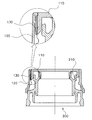
図1を参照すると、本発明に従う密閉部材は、射出成形により全体が樹脂材料で形成される。密閉部材は、気密封止用の容器の開口部を囲んで取り付けられた封止部110と、前記封止部110に対して縦方向に可動な封止部110の外側に取り付けたカバー部120を有する。
Referring to FIG. 1, the sealing member according to the present invention is entirely formed of a resin material by injection molding. The sealing member includes a
封止部110の下端は、薄い帯状に形成された結合バンド130によりカバー部120の上端に結合され、結合バンドは折り曲げられる様な薄さである。
The lower end of the sealing
封止部110は、回転対称に形成された係止突起112を有し、これにより係止突起112が容器に形成された係止縁に固定される。係止突起112の数は、容器の大きさ、気密度等を考慮して決められる。
The sealing
それぞれの係止突起112は、封止部110の下部縁から延びているヒンジ111に結合し、内部に突き出るように形成される。
Each
ヒンジ111は、係止突起112に比較してより薄く、各係止突起112は、回転軸として作用する対応のヒンジ111の周りを回転できる。
The
それぞれの係止突起112は、係止突起の下端に内側に凹んだ溝112aを有し、カバー部120の内側に形成された固定突起121が、溝112aにより支持される。
Each
カバー部120は、カバー部120の外周面の下端で外側で突き出た把持突起122を有し、ユーザが容器の開閉操作をする際に、カバー部120を容易に掴むことができる。好ましくは、二つの把持突起が互いに対向して位置づけられる。
The
例えば、図1は、本発明に従う容器の全体構成を示すために、カバー部から封止部を引き抜いた状態を示す。封止部がカバー部に挿入されている際に、密閉部材の開閉操作が可能であり、他の図面を参照して詳細に説明する。 For example, FIG. 1 shows a state in which the sealing portion is pulled out from the cover portion in order to show the overall configuration of the container according to the present invention. When the sealing portion is inserted into the cover portion, the sealing member can be opened and closed, which will be described in detail with reference to other drawings.
図2を参照すると、封止部110の下端に備えられた係止突起112は、容器に形成された係止縁に固定され、それぞれの係止突起112が好ましくは容器の係止縁に対向する凹曲面112bを有する。それにより、係止突起112が係止縁に固定又は開放される時に、係止突起112が容易に弾性的に変形される。
Referring to FIG. 2,
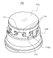
図3は、密閉部材が閉じた状態になる様に容器に密閉部材が取り付けられた状態を示す。封止部110の下端の係止突起112が容器200の係止縁210に固定され、容器が気密状態に保たれる。このとき、封止部110の上端はカバー部120の上端と一致し、封止部110の上端がカバー部120の上端とぴったり重なる。
FIG. 3 shows a state in which the sealing member is attached to the container so that the sealing member is in a closed state. The
封止部110の外側に位置するカバー部120のそれぞれの固定突起121は、全ての係止突起112が、外側に広がらず、容器200の係止縁210に確実に固定される様に、対応する係止突起112の下端の対応する溝112に位置する。
The
それぞれの係止突起112の下部内面は傾斜面112cを有し、密閉部材を取り付けを可能とするとともに、傾斜面112cにより各係止突起112が容器の係止縁210に固定されるのを防ぐ。
The lower inner surface of each
リブ113が封止部110の下部面に付加的に形成され、リブ113が容器の開口部に挿入され、気密状態を高めることができる。
The
カバー部120は、封止部110の外側にピッタリと取り付けられ、カバー部120が封止部110に対して上下に動く様にされる。そして、封止部110とカバー部120の間の上下方向の操作により密閉部材を開閉できるようにしている。
The
カバー部120と封止部110との間の隙間は、カバー部120と封止部110が容易に互いに上下方向に動ける限り、最小化されている。
The gap between the
図4に示す様に、薄い帯状に形成された結合バンド130がカバー部120の上端と封止部110の下端の間に備えられ、カバー部120と封止部110が一体化するように相互に結合されている。結合バンドは結合バンド130がカバー部と封止部間で相対的な上方向及び下方向の動きを妨げることなく折り曲げられる。
As shown in FIG. 4, a
以下、上記の構成の本発明に従う密閉部材の簡単な使用を説明する。 Hereinafter, a simple use of the sealing member according to the present invention having the above-described configuration will be described.
図5に示す様に、密閉部材100が容器200に取り付けられているときに、ユーザが、把持突起122を把持し、カバー部120を上方向に動かし、上方から封止部110を押すと、対応する係止突起112を支持する固定突起121が、カバー部120が上方向に動くので、カバー部120とともに上方向に動かされる。このとき、固定突起121が対応する係止突起112上を動くので、容器200の係止縁210の固定されている係止突起112が、軸として作用するヒンジ111に対して外方向に広げられ、密閉部材100を開けることができる。
As shown in FIG. 5, when the sealing
一方、ユーザが、密閉部材を開ける為に封止部110を押すことも固定することもなくカバー部120のみを引き上げると、カバー部120及び封止部110は、係止突起112が固定突起121により支持されている状態で上方向に動かされる。しかし、この時、係止突起112は固定突起121により支持されているので、係止突起112は係止縁210から容易に離されない。
On the other hand, when the user lifts only the
この様に、ユーザが、密閉部材を開ける為に封止部110を押すことも固定することもなくカバー部120のみを引き上げるときは、密閉部材は開けられない。反対に、密閉部材は封止部とカバー部が同時に上記した様に操作される正常な開封操作を通してのみ開けられる。この様に、本発明に従う密閉部材は、上記説明のように密閉部材の正常な開封操作によってのみ開けられる安全な密閉部材として機能する。
In this way, when the user pulls up only the
次に、図6は、それぞれの固定突起121が対応するヒンジ111の外側に位置する場合に密閉部材が開けられる状態を示している。この時、封止部110の上端はカバー部120の上端の下に位置している。
Next, FIG. 6 shows a state in which the sealing member is opened when each fixing
容器上の密閉部材を押すことにより、密閉部材が容器に取り付けられる。このとき、容器の係止縁210の上端が、それぞれの係止突起112の下端面に対応する傾斜面112cに接触し、それぞれの係止突起112は容器の係止縁210上に動き固定される。同時に、カバー部120が下方向に動き、それぞれの固定突起121が係止突起112の対応する溝112aに挿入される。そうして、それぞれの固定突起121は、係止突起112を支持してそれぞれの係止突起112が外側に広がるのを防ぎ、容器が閉められる(図5参照)。
By pushing the sealing member on the container, the sealing member is attached to the container. At this time, the upper end of the locking
図7は、本発明に従う密閉部材に使用される係止突起の変形例を示す図である。 FIG. 7 is a view showing a modification of the locking projection used in the sealing member according to the present invention.
図7は、図3に示す係止突起の一部分を示す拡大図である。上記に説明した様に、密閉部材を開くためにユーザがカバー部を上方向に動かし、同時に封止部を押すと、密閉部材が開けられる。 FIG. 7 is an enlarged view showing a part of the locking projection shown in FIG. 3. As described above, when the user moves the cover portion upward in order to open the sealing member and simultaneously presses the sealing portion, the sealing member is opened.
この開封処理において、係止突起112を支持する固定突起121が、係止突起112の溝部112aから上方向に動き、固定突起121が溝部112から外れる。この開封処理の間、固定突起121と係止突起112が圧縮され、弾性的に変形される。
In this unsealing process, the fixing
したがって、密閉部材を開ける為に、固定突起121が係止突起112の溝部112aから完全に離れる程の変位d1において、大きな操作力が要求される。
Therefore, in order to open the sealing member, a large operating force is required at a displacement d1 such that the fixing
図8は、図7に示される様に係止突起を有する密閉部が開いている時のカバー部と封止部間における操作力Fと垂直方向変位の関係を示すグラフである。ここでは、ユーザは、密閉部材を開けるための縦方向変位d1まで、大きな操作力が必要であることを示している。 FIG. 8 is a graph showing the relationship between the operating force F and the vertical displacement between the cover part and the sealing part when the sealing part having the locking projection is open as shown in FIG. Here, the user indicates that a large operating force is required up to the longitudinal displacement d1 for opening the sealing member.
上述した様に、密閉部材を開く為の操作力は、固定突起の大きさ(突起の程度)と係止突起の溝の深さ等に依存して決められる。従って、操作力は、密閉部材の用途に従って選択される。例えば、容器の内容物が、炭酸飲料の様な大きな内部圧を有する場合、密閉部材は、容易に開かないように好ましく設計される。この場合、固定突起の大きさ及び係止突起の溝の深さ等は、大きな操作力を有する様に選択される。さもなければ、密閉部材における固定突起の数及び係止突起の数を増加しても良い。 As described above, the operation force for opening the sealing member is determined depending on the size of the fixing protrusion (the degree of the protrusion), the depth of the groove of the locking protrusion, and the like. Therefore, the operating force is selected according to the application of the sealing member. For example, if the contents of the container have a large internal pressure, such as a carbonated beverage, the sealing member is preferably designed so that it does not open easily. In this case, the size of the fixing protrusion, the depth of the groove of the locking protrusion, and the like are selected so as to have a large operating force. Otherwise, the number of fixing protrusions and the number of locking protrusions in the sealing member may be increased.
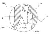
図9は、本発明に従う密閉部材に用いられる係止突起の一変形例を示す。本発明の密閉部材において、係止突起112は、係止突起112の下端で垂直方向に対して傾いた傾斜面112dを有し、固定突起121が前記傾斜面112dにより支持される。
FIG. 9 shows a modification of the locking projection used in the sealing member according to the present invention. In the sealing member of the present invention, the locking
図10は、図9に示される様に係止突起を有する密閉部が開いている時のカバー部と封止部間における操作力Fと垂直方向変位dの関係を示すグラフである。ここで、開封処理の間、係止突起112の傾斜面に沿って、固定突起121が動くので、図7の実施例と比較すると、ユーザは、傾斜面の境界線に対応する垂直位置変位d1まで比較的小さな操作力F2で、密閉部材を開けることができる。
FIG. 10 is a graph showing the relationship between the operating force F and the vertical displacement d between the cover part and the sealing part when the sealing part having the locking projection is open as shown in FIG. Here, since the fixing
上記した様に、密閉部材を開く為の操作力の大きさは、係止突起の形状に依存して変えられる。したがって、操作力は密閉部材の用途によって選択される。 As described above, the magnitude of the operating force for opening the sealing member can be changed depending on the shape of the locking projection. Therefore, the operating force is selected according to the application of the sealing member.
例えば、密閉部材の容易な開閉のみが容器にとって重要と考えられる場合は、容器は、図9の変形例で示した様に比較的小さな操作力で容易に開閉される様に設計される。しかし、容器が薬品や化学物を収容する場合は、子供が容易に開けられないように、あるいは炭酸飲料等の比較的に大きな内部圧力を有する内容物である場合は、密閉部材は図7に示す変形例のように大きな操作力を有する様に設計される。 For example, when it is considered that only easy opening and closing of the sealing member is important for the container, the container is designed to be easily opened and closed with a relatively small operating force as shown in the modification of FIG. However, when the container contains chemicals or chemicals, the sealing member is shown in FIG. 7 so that the child cannot easily open it or the contents have a relatively large internal pressure such as carbonated drinks. It is designed to have a large operating force as in the modification shown.
図7及び図9を参照して、密閉部材を開くための操作力の大きさが係止突起の形状の変更により変わることを示した。しかし、追加的あるいは、代替的に、密閉部材を開くのに要する操作力は、固定突起の大きさ及び又は形状を変えることにより、種々の方法をとり得ることは当業者により自明である。 7 and 9, it has been shown that the magnitude of the operating force for opening the sealing member is changed by changing the shape of the locking protrusion. However, it will be apparent to those skilled in the art that the operating force required to open the sealing member additionally or alternatively may take various ways by changing the size and / or shape of the fixing protrusion.
さて、図11乃至図13は、本発明に従う他の実施例を示している。本発明に従う密閉部材100において、係止突起112の上端から上方向に突き出るレバー突起114を追加的に備えることもできる。
11 to 13 show another embodiment according to the present invention. In the sealing
図11に示す様に、二つのレバー突起114がヒンジ111に隣接する係止突起112の両サイドの上端部から上方向に突き出ている。
As shown in FIG. 11, the two
密閉部材が開けられた後、開けられた密閉部材を容器に再び取り付ける過程で、それぞれのレバー突起114が係止突起と容器の係止縁との干渉を防ぐことができる。それにより、密閉部材は何ら不都合なしに、容器に容易に再び取り付けできる。
In the process of reattaching the opened sealing member to the container after the sealing member is opened, each
例えば、図6は、密閉部材が開けられた後、係止突起112が内側に折り曲げられないことを示している。係止突起112が内側に折り曲げられると、開けられた密閉部材を再取り付けする処理の過程で、係止突起112は容器の係止縁210により固定され、そうして密閉部材は閉じられなくなる。
For example, FIG. 6 shows that the locking
このように、密閉部材が開けられた後、レバー突起114が係止突起112を永久に外方向に広げ、容器に密閉部材を再び取り付ける過程で、レバー突起114が係止突起と容器の係止縁間の干渉を防ぐことができる。これにより、密閉部材が容器に誤って取り付けられることを防ぐことができる。
As described above, after the sealing member is opened, the
より具体的に、図12は、上記に説明したと同じ処理により密閉部材を開けた後、固定突起121がヒンジの近傍に位置し、固定突起121がレバー突起114が内側方向に押され、ヒンジ111に結合した係止突起112が外方向に広がるのを許容することを示している。
More specifically, in FIG. 12, after opening the sealing member by the same process as described above, the fixed
上記した様に密閉部材が開けられた後、係止突起が永久に外方向に広げられるので、容器の係止縁210は、開けられた密閉部材の再取り付けの過程で、係止突起112の下端で傾斜面112cと常に接触する。それにより、密閉部材は、容易に容器に取り付けられる。
After the sealing member is opened as described above, the locking projection is permanently spread outward, so that the locking
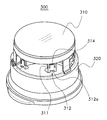
図13は、本発明に従う密閉部材において使用されるレバー突起の変型例であり、一つのレバー突起314が2つのヒンジ311により結合する係止突起312の中心近傍に上方に突き出ることができる。
FIG. 13 is a modification of the lever projection used in the sealing member according to the present invention, and one
固定突起が挿入される溝312aはレバー突起314が位置する係止突起312の下端近傍に形成される。密閉部材の開閉処理は、上記した実施例と同様である。
The
図14乃至図16は、本発明に従う密閉部材の更に他の実施例を示す。 14 to 16 show still another embodiment of the sealing member according to the present invention.
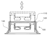
図14に示す様に、本発明に従う密閉部材において、少なくとも2本の案内バー140が垂直下方向に封止部110の下部リムに追加的に固定される。それにより案内バー140の下端がカバー部120の内周面に接触される。
As shown in FIG. 14, in the sealing member according to the present invention, at least two
参考として、図14は、図1に示したように射出成型により製造される密閉部材の開口を示している。密閉部材の射出成型された初めの状態において、封止部110は上部に位置する。しかし、封止部110が、上記した様に密閉部材が容器に結合され、閉じられると、封止部110の上端は、カバー部120の上端にぴったり重なる(図3参照)。
For reference, FIG. 14 shows an opening of a sealing member manufactured by injection molding as shown in FIG. In the initial state where the sealing member is injection-molded, the sealing
図14に示す様に、射出成型により製造された密閉部材において、封止部及びカバー部は薄い結合バンドのみにより相互に結合されている。このように、封止部とカバー部を支持する為に追加的な補助手段を有しない場合、薄い結合バンドが弱いために、結合バンドは、射出成型で製造された密閉部材が容器に取り付けられるまでの密閉部材の取り扱いあるいは運搬処理を通して容易に裂けたり、傷付けられる。 As shown in FIG. 14, in the sealing member manufactured by injection molding, the sealing portion and the cover portion are coupled to each other only by a thin coupling band. As described above, when there is no additional auxiliary means for supporting the sealing portion and the cover portion, since the thin binding band is weak, the sealing member manufactured by injection molding is attached to the container. It can be easily torn or damaged through the handling or transportation process of the sealing member up to.
したがって、本発明に従う密閉部材に備えられる案内バーは、上記のように製造された密閉部材が容器に取り付けられるまでの密閉部材の取り扱い中に結合バンドが傷つけられるのを防止する。そして、容器に密閉部材が取り付けられた後、封止部とカバー部間の相対的な上下方向の動きをガイドする。 Therefore, the guide bar provided in the sealing member according to the present invention prevents the binding band from being damaged during the handling of the sealing member until the sealing member manufactured as described above is attached to the container. Then, after the sealing member is attached to the container, the relative vertical movement between the sealing portion and the cover portion is guided.
図15を参照すると、射出成型により、封止部110に固定された案内バー140の上端140aは、上端140aが封止部110にしっかりと固定される様に厚く、カバー部120の上端の内円周面に固定された案内バー140の下端140bは下端140bが上端140aと較べてカバー部120の上端部に弱く固定される様に薄い。
Referring to FIG. 15, the
一方、射出成型された密閉部材を容器に初めて取り付ける処理において、強く下方向に押され、封止部110が容器の開口に予備的に取り付けられると、封止部110が下方向に動かされ、容器に取り付けられ、案内バー140の下端140bとカバー部120の間の結合が壊される。
On the other hand, in the process of attaching the injection-molded sealing member to the container for the first time, when strongly pressed downward and the sealing
図16に示す様に、密閉部材が容器に取り付けられた後、案内バー140は封止部110とともに垂直方向に動かされる。案内バー140がカバー部120の内面壁に沿って動かされるので、案内バー140は封止部とカバー部との間に隙間を形成する。それにより案内バー140は封止部とカバー部の上下方向の動きを容易にする案内機能を果たす。
As shown in FIG. 16, after the sealing member is attached to the container, the
図17は、本発明に従う密閉部材の更なる実施例を示す。先の実施例は、封止部とカバー部が結合バンドで互いに結合されていることを示しているが、封止部とカバー部はこの実施例では結合バンドで結合されていることを必要としない。 FIG. 17 shows a further embodiment of a sealing member according to the present invention. The previous example shows that the sealing part and the cover part are coupled to each other by a coupling band, but the sealing part and the cover part need to be coupled by a coupling band in this example. do not do.
封止部410とカバー部420が別個のプロセスにより製造され、図17に示す様に密閉部材として一体に組み立てられるが、密閉部材は先の実施例で述べられたと同じ方法で操作されることは当業者にとって明らかである。
The sealing
一方、カバー部と結合バンドとの間に弱く結合された補助バンドが付加的に備えられ、あるレベルの操作力を与えることで密閉部材が初めて開けられる時、その補助バンドが切られる。 On the other hand, a weakly coupled auxiliary band is additionally provided between the cover part and the coupling band, and when the sealing member is opened for the first time by applying a certain level of operating force, the auxiliary band is cut.
ユーザは、補助バンドが切られているか否かを判定することで、容器の内容物が既に使用された否かをチェックすることができる。 The user can check whether the contents of the container have already been used by determining whether the auxiliary band is cut.
上記の実施例は、本発明の思想を詳細に示す為の単なる例として理解されるべきであり、従って、本発明の範囲は、図面及び実施例のいずれにも限定されるものではない。 The above embodiments should be understood as merely examples for illustrating the concept of the present invention in detail, and therefore the scope of the present invention is not limited to either the drawings or the embodiments.
Claims (8)
容器の開口に取り付けられ前記容器を封止する封止部と、
それぞれ前記封止部の下側縁から延びるヒンジに結合し、内側に突起し、前記容器に形成された係止縁に固定される、複数の係止突起と、
リング状で、前記封止部に対して垂直に動くように前記封止部の外側に取り付けられるカバー部と、
前記カバー部の内側円周面から突き出て前記係止突起を支持する複数の固定突起と、
さらに、前記係止突起の上端から上方向に突き出たレバー突起を有する密閉部材。 A sealing member,
A sealing part attached to the opening of the container and sealing the container;
A plurality of locking projections, each coupled to a hinge extending from a lower edge of the sealing portion, protruding inward, and fixed to a locking edge formed on the container;
A cover portion attached to the outside of the sealing portion so as to move in a ring shape and perpendicular to the sealing portion;
A plurality of fixing protrusions protruding from the inner circumferential surface of the cover portion and supporting the locking protrusions ;
Further, a sealing member having a lever protrusion protruding upward from the upper end of the locking protrusion .
前記係止突起は、前記係止縁に対面する凹曲面を有する密閉部材。 In claim 1,
The locking projection is a sealing member having a concave curved surface facing the locking edge.
容器の開口に取り付けられ前記容器を封止する封止部と、
それぞれ前記封止部の下側縁から延びるヒンジに結合し、内側に突起し、前記容器に形成された係止縁に固定される、複数の係止突起と、
リング状で、前記封止部に対して垂直に動くように前記封止部の外側に取り付けられるカバー部と、
前記カバー部の内側円周面から突き出て前記係止突起を支持する複数の固定突起を有し、
さらに、前記カバー部の外周面の下端に、外側に突き出た把持突起を有する密閉部材。 A sealing member,
A sealing part attached to the opening of the container and sealing the container;
A plurality of locking projections, each coupled to a hinge extending from a lower edge of the sealing portion, protruding inward, and fixed to a locking edge formed on the container;
A cover portion attached to the outside of the sealing portion so as to move in a ring shape and perpendicular to the sealing portion;
A plurality of fixing protrusions protruding from the inner circumferential surface of the cover portion and supporting the locking protrusions;
Furthermore, the sealing member which has the holding | grip protrusion protruded outside at the lower end of the outer peripheral surface of the said cover part.
前記係止突起は、その下端に溝を有し、前記固定突起を支持する密閉部材。 In claim 1,
The locking protrusion has a groove at a lower end thereof, and is a sealing member that supports the fixing protrusion.
前記係止突起はその下端に、前記固定突起を支持する傾斜面を有し、前記傾斜面は垂直方向に対して傾斜している密閉部材。 In claim 1,
The locking protrusion has an inclined surface supporting the fixed protrusion at a lower end thereof, and the inclined surface is inclined with respect to a vertical direction.
容器の開口に取り付けられ前記容器を封止する封止部と、
それぞれ前記封止部の下側縁から延びるヒンジに結合し、内側に突起し、前記容器に形成された係止縁に固定される、複数の係止突起と、
リング状で、前記封止部に対して垂直に動くように前記封止部の外側に取り付けられるカバー部と、
前記カバー部の内側円周面から突き出て前記係止突起を支持する複数の固定突起を有し、
少なくとも2本の案内バーが、更に前記封止部の下端縁に垂直に下方向に固定され、前記案内バーの下端が前記カバー部の内周面に接触される密閉部材。 A sealing member,
A sealing part attached to the opening of the container and sealing the container;
A plurality of locking projections, each coupled to a hinge extending from a lower edge of the sealing portion, protruding inward, and fixed to a locking edge formed on the container;
A cover portion attached to the outside of the sealing portion so as to move in a ring shape and perpendicular to the sealing portion;
A plurality of fixing protrusions protruding from the inner circumferential surface of the cover portion and supporting the locking protrusions;
A sealing member in which at least two guide bars are further fixed vertically downward to the lower end edge of the sealing portion, and the lower end of the guide bar is in contact with the inner peripheral surface of the cover portion.
容器の開口に取り付けられ前記容器を封止する封止部と、
それぞれ前記封止部の下側縁から延びるヒンジに結合し、内側に突起し、前記容器に形成された係止縁に固定される、複数の係止突起と、
リング状で、前記封止部に対して垂直に動くように前記封止部の外側に取り付けられるカバー部と、
前記カバー部の内側円周面から突き出て前記係止突起を支持する複数の固定突起と、
さらに、前記カバー部の上端と前記封止部の下端に結合する複数の結合バンドを有する密閉部材。 A sealing member,
A sealing part attached to the opening of the container and sealing the container;
A plurality of locking projections, each coupled to a hinge extending from a lower edge of the sealing portion, protruding inward, and fixed to a locking edge formed on the container;
A cover portion attached to the outside of the sealing portion so as to move in a ring shape and perpendicular to the sealing portion;
A plurality of fixing protrusions protruding from the inner circumferential surface of the cover portion and supporting the locking protrusions;
Furthermore, the sealing member which has a some coupling | bonding band couple | bonded with the upper end of the said cover part, and the lower end of the said sealing part.
容器本体の開口の外周面から突き出た係止縁を有する容器本体と、
前記開口に結合して前記容器を封止する密閉部材を有し、
前記密閉部材は、
前記容器の開口に取り付けられ前記容器本体を封止する封止部と、
それぞれ前記封止部の下側縁から延びるヒンジに結合し、内側に突起し、前記容器に形成された係止縁に固定される、複数の係止突起と、
リング状で、前記封止部に対して垂直に動くように前記封止部の外側に取り付けられるカバー部と、
前記カバー部の内側円周面から突き出て前記係止突起を支持する複数の固定突起と、
さらに、前記係止突起の上端から上方向に突き出たレバー突起を有する容器。 A container,
A container body having a locking edge protruding from the outer peripheral surface of the opening of the container body;
A sealing member that is coupled to the opening and seals the container;
The sealing member is
A sealing part that is attached to the opening of the container and seals the container body;
A plurality of locking projections, each coupled to a hinge extending from a lower edge of the sealing portion, protruding inward, and fixed to a locking edge formed on the container;
A cover portion attached to the outside of the sealing portion so as to move in a ring shape and perpendicular to the sealing portion;
A plurality of fixing protrusions protruding from the inner circumferential surface of the cover portion and supporting the locking protrusions ;
Furthermore, the container which has the lever protrusion protruded upwards from the upper end of the said latching protrusion .
Applications Claiming Priority (3)
| Application Number | Priority Date | Filing Date | Title |
|---|---|---|---|
| KR1020090055409A KR101121860B1 (en) | 2009-06-22 | 2009-06-22 | Stopper and a container having the same |
| KR10-2009-0055409 | 2009-06-22 | ||
| PCT/KR2010/003957 WO2010151009A2 (en) | 2009-06-22 | 2010-06-18 | Stopper and container having stopper |
Publications (2)
| Publication Number | Publication Date |
|---|---|
| JP2012530654A JP2012530654A (en) | 2012-12-06 |
| JP5607151B2 true JP5607151B2 (en) | 2014-10-15 |
Family
ID=43387013
Family Applications (1)
| Application Number | Title | Priority Date | Filing Date |
|---|---|---|---|
| JP2012515992A Active JP5607151B2 (en) | 2009-06-22 | 2010-06-18 | Sealing member and container having the same |
Country Status (10)
| Country | Link |
|---|---|
| US (1) | US8919595B2 (en) |
| EP (1) | EP2447180B1 (en) |
| JP (1) | JP5607151B2 (en) |
| KR (1) | KR101121860B1 (en) |
| CN (1) | CN102803089B (en) |
| ES (1) | ES2523352T3 (en) |
| MY (1) | MY155490A (en) |
| PL (1) | PL2447180T3 (en) |
| TW (1) | TWI454410B (en) |
| WO (1) | WO2010151009A2 (en) |
Families Citing this family (10)
| Publication number | Priority date | Publication date | Assignee | Title |
|---|---|---|---|---|
| JP6253407B2 (en) * | 2013-12-28 | 2017-12-27 | 日本クロージャー株式会社 | Easy-opening type cap and its plugging method |
| JP6322446B2 (en) * | 2014-03-04 | 2018-05-09 | 日本クロージャー株式会社 | Plastic container lid |
| JP6468793B2 (en) * | 2014-10-21 | 2019-02-13 | 日本クロージャー株式会社 | Plastic container lid |
| JP6503215B2 (en) * | 2015-03-31 | 2019-04-17 | 日本クロージャー株式会社 | Method and apparatus for attaching a container lid to the mouth and neck of a container |
| JP6438824B2 (en) * | 2015-03-31 | 2018-12-19 | 日本クロージャー株式会社 | Plastic container lid |
| JP6503238B2 (en) * | 2015-06-22 | 2019-04-17 | 日本クロージャー株式会社 | Plastic container lid |
| CN106672423B (en) * | 2016-12-14 | 2018-08-10 | 林颖 | Bottle cap connection structure and water bottle |
| FR3086277B1 (en) * | 2018-09-24 | 2021-05-28 | Albea Services | REMOVABLE COVER FOR DISTRIBUTION BOTTLE |
| FR3098505B1 (en) * | 2019-07-09 | 2021-06-04 | A Raymond Et Cie | snap-off locking cap for neck container |
| KR102096794B1 (en) | 2019-11-18 | 2020-04-03 | 채동석 | One-touch opening and closing structure of stopper and container |
Family Cites Families (26)
| Publication number | Priority date | Publication date | Assignee | Title |
|---|---|---|---|---|
| US3952901A (en) * | 1974-07-02 | 1976-04-27 | Dairy Cap Corporation | Tamper-proof overcap construction |
| FR2352718A1 (en) * | 1976-05-26 | 1977-12-23 | Probst Edgar | Bottle closure cooperating with groove in bottle neck - has press down closing ring kept in closed position by tear off tab between ring and closure flange |
| CH643201A5 (en) * | 1979-11-07 | 1984-05-30 | Createchnic Patent Ag | SEALING CAP AND METHOD FOR THEIR PRODUCTION. |
| US4364483A (en) * | 1981-02-02 | 1982-12-21 | Erich Golde | Child proof screw cap |
| US4366921A (en) * | 1981-09-28 | 1983-01-04 | Ethyl Products Company | Child-resistant closure device |
| JPS5993660A (en) * | 1982-11-22 | 1984-05-30 | 株式会社 大井製作所 | Singly operated vessel cover |
| US4519514A (en) * | 1984-03-20 | 1985-05-28 | Robert Linkletter Associates, Inc. | Tamper resistant and tamper evident closures |
| US4516684A (en) * | 1984-04-10 | 1985-05-14 | Continental Packaging Company, Inc. | Resealable closure |
| DE3715175C1 (en) * | 1987-05-07 | 1988-11-24 | Pohl Metall Kunststoff | Cap for infusion and transfusion bottles |
| US5314084A (en) * | 1992-08-21 | 1994-05-24 | The West Company, Incorporated | Two piece all plastic seal |
| DE4314923C2 (en) * | 1993-05-06 | 1998-08-27 | West Company Deutschland Gmbh | Cap for closing a bottle |
| GB9322113D0 (en) * | 1993-10-27 | 1993-12-15 | Sturk Ron | Closure for containers |
| JPH09278051A (en) * | 1996-04-09 | 1997-10-28 | Taisei Kako Kk | Crown-form lid having locking mechanism |
| US5927529A (en) * | 1996-08-19 | 1999-07-27 | Magenta Corporation | Child resistant container |
| US5960972A (en) * | 1996-11-15 | 1999-10-05 | Constancio Larguia, Sr. | Container cap with interlocked safety closure |
| BR9707313A (en) * | 1996-11-25 | 1999-05-25 | Diseno Ind Mago S L | Airtight closing cap |
| WO2004108549A1 (en) * | 2003-06-03 | 2004-12-16 | Taisei Kako Co., Ltd. | Cap of container |
| KR100575259B1 (en) | 2003-07-25 | 2006-04-28 | 채동석 | One touch-type stopper and a container having the same |
| JP4504370B2 (en) * | 2003-07-25 | 2010-07-14 | チェイ、ドン−シュク | One-touch stopper and container having one-touch stopper |
| NZ547489A (en) * | 2003-11-25 | 2010-04-30 | Nci Holdings Pty Ltd | A reusable closure for a container with a locking ring that engadges securing lugs to clamp the lid to the container |
| US7401706B2 (en) * | 2004-09-27 | 2008-07-22 | Rexam Prescription Products Inc. | Closure and package having child-resistant and non-child-resistant modes of operation |
| KR200385497Y1 (en) | 2005-03-11 | 2005-05-27 | 채동석 | Stopper and a container having the same |
| KR200394215Y1 (en) * | 2005-06-03 | 2005-09-01 | 장재수 | Vessel for Cyanoacrylate adhesive |
| EP1971531B1 (en) * | 2005-11-30 | 2009-08-19 | Biocorp Recherche et Developpement | Plug device for a container and container provided with one such device |
| KR100757795B1 (en) * | 2006-06-21 | 2007-09-11 | 채동석 | Closure and a container having the same |
| EP2205502A1 (en) * | 2007-10-18 | 2010-07-14 | Medical Instill Technologies, Inc. | Container having a closure and removable resealable stopper for sealing a substance therein, and related method |
-
2009
- 2009-06-22 KR KR1020090055409A patent/KR101121860B1/en active IP Right Grant
-
2010
- 2010-06-18 JP JP2012515992A patent/JP5607151B2/en active Active
- 2010-06-18 ES ES10792291.6T patent/ES2523352T3/en active Active
- 2010-06-18 PL PL10792291T patent/PL2447180T3/en unknown
- 2010-06-18 MY MYPI2011006216A patent/MY155490A/en unknown
- 2010-06-18 CN CN201080027445.9A patent/CN102803089B/en active Active
- 2010-06-18 US US13/379,423 patent/US8919595B2/en active Active
- 2010-06-18 WO PCT/KR2010/003957 patent/WO2010151009A2/en active Application Filing
- 2010-06-18 EP EP10792291.6A patent/EP2447180B1/en active Active
- 2010-06-21 TW TW099120034A patent/TWI454410B/en not_active IP Right Cessation
Also Published As
| Publication number | Publication date |
|---|---|
| EP2447180A2 (en) | 2012-05-02 |
| KR101121860B1 (en) | 2012-03-20 |
| ES2523352T3 (en) | 2014-11-25 |
| EP2447180B1 (en) | 2014-08-13 |
| CN102803089A (en) | 2012-11-28 |
| JP2012530654A (en) | 2012-12-06 |
| CN102803089B (en) | 2015-02-11 |
| WO2010151009A3 (en) | 2011-03-31 |
| MY155490A (en) | 2015-10-30 |
| US20120103993A1 (en) | 2012-05-03 |
| US8919595B2 (en) | 2014-12-30 |
| EP2447180A4 (en) | 2013-07-03 |
| WO2010151009A2 (en) | 2010-12-29 |
| TWI454410B (en) | 2014-10-01 |
| TW201119914A (en) | 2011-06-16 |
| PL2447180T3 (en) | 2015-01-30 |
| KR20100137135A (en) | 2010-12-30 |
Similar Documents
| Publication | Publication Date | Title |
|---|---|---|
| JP5607151B2 (en) | Sealing member and container having the same | |
| JP5426692B2 (en) | Container lid | |
| US8567621B2 (en) | Closure and container having the same | |
| CN101267993B (en) | Sealing device for a container | |
| KR20060015011A (en) | A reclosable package | |
| MXPA06009299A (en) | Dispensing closure. | |
| JP2011522751A (en) | Beverage can lid seal | |
| US20120006824A1 (en) | Sealing Lid For A Container | |
| JP4721219B2 (en) | cap | |
| KR101876732B1 (en) | Container structure | |
| WO2001056899A1 (en) | Cover body of container | |
| WO2007148853A1 (en) | Easy opening airtight container | |
| JP2009502689A (en) | Container lid for storage container | |
| JP2005047511A (en) | Container | |
| JP2022535777A (en) | Closed container with soft hinge and double injection structure | |
| KR200395480Y1 (en) | A cover of a vessel | |
| KR200261828Y1 (en) | a cap for airtight instrument | |
| KR101845361B1 (en) | Tray container structure | |
| KR200390444Y1 (en) | A lid of a drinking bottle | |
| KR100787298B1 (en) | Resealable sliding can end | |
| KR200253340Y1 (en) | Vacuum receptacle | |
| KR200339588Y1 (en) | One touch cap of bottle | |
| KR200213038Y1 (en) | structure for coupling a bottle and a cap | |
| KR200210342Y1 (en) | Open-tab having stopper | |
| KR200379451Y1 (en) | A device for mixing drinks |
Legal Events
| Date | Code | Title | Description |
|---|---|---|---|
| A621 | Written request for application examination |
Free format text: JAPANESE INTERMEDIATE CODE: A621 Effective date: 20121012 |
|
| A977 | Report on retrieval |
Free format text: JAPANESE INTERMEDIATE CODE: A971007 Effective date: 20130930 |
|
| A131 | Notification of reasons for refusal |
Free format text: JAPANESE INTERMEDIATE CODE: A131 Effective date: 20131203 |
|
| A521 | Request for written amendment filed |
Free format text: JAPANESE INTERMEDIATE CODE: A523 Effective date: 20140219 |
|
| TRDD | Decision of grant or rejection written | ||
| A01 | Written decision to grant a patent or to grant a registration (utility model) |
Free format text: JAPANESE INTERMEDIATE CODE: A01 Effective date: 20140805 |
|
| A61 | First payment of annual fees (during grant procedure) |
Free format text: JAPANESE INTERMEDIATE CODE: A61 Effective date: 20140827 |
|
| R150 | Certificate of patent or registration of utility model |
Ref document number: 5607151 Country of ref document: JP Free format text: JAPANESE INTERMEDIATE CODE: R150 |
|
| R250 | Receipt of annual fees |
Free format text: JAPANESE INTERMEDIATE CODE: R250 |
|
| R250 | Receipt of annual fees |
Free format text: JAPANESE INTERMEDIATE CODE: R250 |
|
| R250 | Receipt of annual fees |
Free format text: JAPANESE INTERMEDIATE CODE: R250 |
|
| R250 | Receipt of annual fees |
Free format text: JAPANESE INTERMEDIATE CODE: R250 |
|
| R250 | Receipt of annual fees |
Free format text: JAPANESE INTERMEDIATE CODE: R250 |
|
| R250 | Receipt of annual fees |
Free format text: JAPANESE INTERMEDIATE CODE: R250 |
|
| R250 | Receipt of annual fees |
Free format text: JAPANESE INTERMEDIATE CODE: R250 |