JP5606451B2 - Clutch device - Google Patents
Clutch device Download PDFInfo
- Publication number
- JP5606451B2 JP5606451B2 JP2011545623A JP2011545623A JP5606451B2 JP 5606451 B2 JP5606451 B2 JP 5606451B2 JP 2011545623 A JP2011545623 A JP 2011545623A JP 2011545623 A JP2011545623 A JP 2011545623A JP 5606451 B2 JP5606451 B2 JP 5606451B2
- Authority
- JP
- Japan
- Prior art keywords
- plate
- clutch
- clutch device
- carrier
- casing
- Prior art date
- Legal status (The legal status is an assumption and is not a legal conclusion. Google has not performed a legal analysis and makes no representation as to the accuracy of the status listed.)
- Active
Links
Images


Classifications
-
- F—MECHANICAL ENGINEERING; LIGHTING; HEATING; WEAPONS; BLASTING
- F16—ENGINEERING ELEMENTS AND UNITS; GENERAL MEASURES FOR PRODUCING AND MAINTAINING EFFECTIVE FUNCTIONING OF MACHINES OR INSTALLATIONS; THERMAL INSULATION IN GENERAL
- F16D—COUPLINGS FOR TRANSMITTING ROTATION; CLUTCHES; BRAKES
- F16D13/00—Friction clutches
- F16D13/58—Details
- F16D13/60—Clutching elements
- F16D13/64—Clutch-plates; Clutch-lamellae
- F16D13/68—Attachments of plates or lamellae to their supports
- F16D13/683—Attachments of plates or lamellae to their supports for clutches with multiple lamellae
-
- F—MECHANICAL ENGINEERING; LIGHTING; HEATING; WEAPONS; BLASTING
- F16—ENGINEERING ELEMENTS AND UNITS; GENERAL MEASURES FOR PRODUCING AND MAINTAINING EFFECTIVE FUNCTIONING OF MACHINES OR INSTALLATIONS; THERMAL INSULATION IN GENERAL
- F16D—COUPLINGS FOR TRANSMITTING ROTATION; CLUTCHES; BRAKES
- F16D21/00—Systems comprising a plurality of actuated clutches
- F16D21/02—Systems comprising a plurality of actuated clutches for interconnecting three or more shafts or other transmission members in different ways
- F16D21/06—Systems comprising a plurality of actuated clutches for interconnecting three or more shafts or other transmission members in different ways at least two driving shafts or two driven shafts being concentric
-
- F—MECHANICAL ENGINEERING; LIGHTING; HEATING; WEAPONS; BLASTING
- F16—ENGINEERING ELEMENTS AND UNITS; GENERAL MEASURES FOR PRODUCING AND MAINTAINING EFFECTIVE FUNCTIONING OF MACHINES OR INSTALLATIONS; THERMAL INSULATION IN GENERAL
- F16D—COUPLINGS FOR TRANSMITTING ROTATION; CLUTCHES; BRAKES
- F16D25/00—Fluid-actuated clutches
- F16D25/06—Fluid-actuated clutches in which the fluid actuates a piston incorporated in, i.e. rotating with the clutch
- F16D25/062—Fluid-actuated clutches in which the fluid actuates a piston incorporated in, i.e. rotating with the clutch the clutch having friction surfaces
- F16D25/063—Fluid-actuated clutches in which the fluid actuates a piston incorporated in, i.e. rotating with the clutch the clutch having friction surfaces with clutch members exclusively moving axially
- F16D25/0635—Fluid-actuated clutches in which the fluid actuates a piston incorporated in, i.e. rotating with the clutch the clutch having friction surfaces with clutch members exclusively moving axially with flat friction surfaces, e.g. discs
- F16D25/0638—Fluid-actuated clutches in which the fluid actuates a piston incorporated in, i.e. rotating with the clutch the clutch having friction surfaces with clutch members exclusively moving axially with flat friction surfaces, e.g. discs with more than two discs, e.g. multiple lamellae
-
- F—MECHANICAL ENGINEERING; LIGHTING; HEATING; WEAPONS; BLASTING
- F16—ENGINEERING ELEMENTS AND UNITS; GENERAL MEASURES FOR PRODUCING AND MAINTAINING EFFECTIVE FUNCTIONING OF MACHINES OR INSTALLATIONS; THERMAL INSULATION IN GENERAL
- F16D—COUPLINGS FOR TRANSMITTING ROTATION; CLUTCHES; BRAKES
- F16D25/00—Fluid-actuated clutches
- F16D25/10—Clutch systems with a plurality of fluid-actuated clutches
-
- F—MECHANICAL ENGINEERING; LIGHTING; HEATING; WEAPONS; BLASTING
- F16—ENGINEERING ELEMENTS AND UNITS; GENERAL MEASURES FOR PRODUCING AND MAINTAINING EFFECTIVE FUNCTIONING OF MACHINES OR INSTALLATIONS; THERMAL INSULATION IN GENERAL
- F16F—SPRINGS; SHOCK-ABSORBERS; MEANS FOR DAMPING VIBRATION
- F16F15/00—Suppression of vibrations in systems; Means or arrangements for avoiding or reducing out-of-balance forces, e.g. due to motion
- F16F15/10—Suppression of vibrations in rotating systems by making use of members moving with the system
- F16F15/14—Suppression of vibrations in rotating systems by making use of members moving with the system using masses freely rotating with the system, i.e. uninvolved in transmitting driveline torque, e.g. rotative dynamic dampers
- F16F15/1407—Suppression of vibrations in rotating systems by making use of members moving with the system using masses freely rotating with the system, i.e. uninvolved in transmitting driveline torque, e.g. rotative dynamic dampers the rotation being limited with respect to the driving means
- F16F15/145—Masses mounted with play with respect to driving means thus enabling free movement over a limited range
-
- F—MECHANICAL ENGINEERING; LIGHTING; HEATING; WEAPONS; BLASTING
- F16—ENGINEERING ELEMENTS AND UNITS; GENERAL MEASURES FOR PRODUCING AND MAINTAINING EFFECTIVE FUNCTIONING OF MACHINES OR INSTALLATIONS; THERMAL INSULATION IN GENERAL
- F16D—COUPLINGS FOR TRANSMITTING ROTATION; CLUTCHES; BRAKES
- F16D21/00—Systems comprising a plurality of actuated clutches
- F16D21/02—Systems comprising a plurality of actuated clutches for interconnecting three or more shafts or other transmission members in different ways
- F16D21/06—Systems comprising a plurality of actuated clutches for interconnecting three or more shafts or other transmission members in different ways at least two driving shafts or two driven shafts being concentric
- F16D2021/0661—Hydraulically actuated multiple lamellae clutches
-
- F—MECHANICAL ENGINEERING; LIGHTING; HEATING; WEAPONS; BLASTING
- F16—ENGINEERING ELEMENTS AND UNITS; GENERAL MEASURES FOR PRODUCING AND MAINTAINING EFFECTIVE FUNCTIONING OF MACHINES OR INSTALLATIONS; THERMAL INSULATION IN GENERAL
- F16D—COUPLINGS FOR TRANSMITTING ROTATION; CLUTCHES; BRAKES
- F16D3/00—Yielding couplings, i.e. with means permitting movement between the connected parts during the drive
- F16D3/50—Yielding couplings, i.e. with means permitting movement between the connected parts during the drive with the coupling parts connected by one or more intermediate members
- F16D3/78—Yielding couplings, i.e. with means permitting movement between the connected parts during the drive with the coupling parts connected by one or more intermediate members shaped as an elastic disc or flat ring, arranged perpendicular to the axis of the coupling parts, different sets of spots of the disc or ring being attached to each coupling part, e.g. Hardy couplings
- F16D3/79—Yielding couplings, i.e. with means permitting movement between the connected parts during the drive with the coupling parts connected by one or more intermediate members shaped as an elastic disc or flat ring, arranged perpendicular to the axis of the coupling parts, different sets of spots of the disc or ring being attached to each coupling part, e.g. Hardy couplings the disc or ring being metallic
Description
本発明は、重畳して配置された2つの湿式クラッチとねじり振動吸振器とを備えたクラッチ装置に関する。 The present invention relates to a clutch device including two wet clutches and a torsional vibration damper arranged in a superimposed manner.
例えば遠心力振り子といったねじり振動吸振器をパワートレインにおいて使用することが、ドイツ連邦共和国特許出願公開第10310831号明細書において公知になっている。さらに湿式クラッチを備えたクラッチ装置が公知になっている。例えばドイツ連邦共和国特許出願公開第102005027610号明細書には、半径方向に重畳して配置されている2つの湿式クラッチを備えたクラッチ装置が開示されている。 The use of a torsional vibration absorber, for example a centrifugal pendulum, in a power train is known from DE 10310831 A1. Furthermore, a clutch device having a wet clutch is known. For example, German Offenlegungsschrift DE 102005027610 discloses a clutch device comprising two wet clutches arranged in a radial overlap.
クラッチ装置の湿室にねじり振動吸振器を収納することは、共振領域の十分な調整を保証する必要があるので困難である。共振領域への障害には、特にトルクを伝達する接続部分の回動遊びが関与する。 It is difficult to accommodate the torsional vibration absorber in the wet chamber of the clutch device because it is necessary to ensure sufficient adjustment of the resonance region. The obstacle to the resonance region particularly involves the rotational play of the connecting portion that transmits torque.
本発明の目的は、特にケーシングに収納された湿式クラッチと関連した、自動車のパワートレインにおけるねじり振動吸振器の使用を改良することである。 The object of the present invention is to improve the use of torsional vibration absorbers in motor vehicle powertrains, particularly in connection with wet clutches housed in a casing.
上記目的は、駆動ユニット及び下流側に配置されている伝動装置を備えたパワートレインのためのクラッチ装置であって、入力側及び出力側のプレートキャリアに取り付けられていてかつ軸線方向に交互に配置されているプレート及び摩擦プレートを有する、駆動ユニットによって駆動されるケーシング内に配置されている少なくとも1つの湿式クラッチを備えており、入力側のプレートキャリアはクラッチボスに不動に取り付けられているキャリアディスクに不動に接合されており、キャリアディスクにねじり振動吸振器、例えば遠心力振り子が配置されていることにより達成される。有利には、少なくとも1つの湿式クラッチとケーシングとの間において有効に配置することができるねじり振動減衰器を、ねじり振動吸振器に並列に接続することができる。例えば湿式クラッチの入力部分は同時にねじり振動減衰器の出力部分であってよい。 The above object is a clutch device for a power train having a drive unit and a transmission device arranged on the downstream side, which is attached to the input and output side plate carriers and arranged alternately in the axial direction. Carrier plate having at least one wet clutch disposed in a casing driven by a drive unit, wherein the plate carrier on the input side is fixedly attached to the clutch boss. This is achieved by arranging a torsional vibration absorber such as a centrifugal pendulum on the carrier disk. Advantageously, a torsional vibration attenuator that can be arranged effectively between the at least one wet clutch and the casing can be connected in parallel to the torsional vibration absorber. For example, the input part of the wet clutch may simultaneously be the output part of the torsional vibration attenuator.
本発明において、少なくとも1つの湿式クラッチの入力部分とのねじり振動吸振器の接合は、入力側のプレートキャリアを介して行われる。金属薄板変形方法により製造された、例えば深絞り加工されたプレートキャリアを使用する場合、トルクを伝達する接続構成部分に対する遊びを伴う接合は、不十分又は高い製造コストによってのみ達成可能な形状接続に基づき十分に排除することはできないので、特に少なくとも1つの湿式クラッチの操作中に振動問題が発生することがある。例えばがたつき音、振動音又は、不快でさらにねじり振動吸振器の機能に不都合に作用する他の振動作用が発生することがあるので、場合によっては上記位置においてねじり振動吸振器を使用することが全くできない。したがって、少なくとも1つのプレートキャリア、例えば少なくとも1つの湿式クラッチの入力側のプレートキャリアを組立て式のプレートキャリアとして構成すると、特に有利であることが分かった。プレートキャリアは軸線方向に平坦に形成可能な接触面を、入力部分のフランジ部分と、ねじり振動吸振器のキャリアディスクとの間に有している。 In the present invention, the torsional vibration absorber is joined to the input portion of at least one wet clutch through a plate carrier on the input side. When using, for example, deep-drawn plate carriers manufactured by sheet metal deformation methods, joining with play to connecting components transmitting torque results in a shape connection that can only be achieved with insufficient or high manufacturing costs. Vibration problems may occur, particularly during the operation of at least one wet clutch, since it cannot be sufficiently eliminated. For example, rattling noise, vibration noise, or other vibration effects that may be uncomfortable and adversely affect the function of the torsional vibration absorber may occur. I can not do at all. Accordingly, it has been found to be particularly advantageous if at least one plate carrier, for example the plate carrier on the input side of at least one wet clutch, is configured as a prefabricated plate carrier. The plate carrier has a contact surface that can be formed flat in the axial direction between the flange portion of the input portion and the carrier disk of the torsional vibration absorber.
有利な構成によれば、組立て式のプレートキャリアは周方向に亘って分配された、少なくとも1つの湿式クラッチのフランジ部分として構成されている入力部分を、キャリアディスクに軸線方向に離間して遊びなしで接合する接合エレメントから形成されている。フランジ部分若しくはキャリアディスクにおける接合エレメントの平坦な接触面により、キャリアディスクと湿式クラッチの入力部分との特に堅固な接合がもたらされるので、入力部分からねじり振動吸振器へのトルクの伝達は規定され、遊びなしで行うことができる。これによりねじり振動吸振器、例えば遠心力振り子は、特に良好に所望の共振周波数若しくは狭い共振領域に合わせて設計することができる。 According to an advantageous configuration, the assembly-type plate carrier is distributed circumferentially and the input part, which is configured as a flange part of at least one wet clutch, is spaced apart from the carrier disk in the axial direction without play. It is formed from the joining element joined by. Since the flat contact surface of the joining element at the flange part or carrier disk provides a particularly tight joint between the carrier disk and the input part of the wet clutch, the transmission of torque from the input part to the torsional vibration absorber is defined, Can be done without play. Thereby, a torsional vibration absorber, for example, a centrifugal pendulum, can be designed particularly well for a desired resonance frequency or narrow resonance region.
本構成において、ねじり振動吸振器にねじり振動減衰器を並列に接続することが特に有利であることが分かった。ねじり振動減衰器はケーシングと少なくとも1つの湿式クラッチとの間に配置されていて、湿式クラッチの出力部分は同様に、少なくとも1つの湿式クラッチの入力部分のフランジ部分により形成されている。さらに例えば半径方向に重畳して配置されている2つの湿式クラッチから成る少なくとも1つの湿式クラッチ装置は、ツインクラッチ伝動装置のために設けられていてよい。本構成において、2つの湿式クラッチの、有利には半径方向外側のプレートキャリア又は両入力側のプレートキャリアが組み立てられていてよい。 In this configuration, it has been found that it is particularly advantageous to connect a torsional vibration attenuator in parallel to the torsional vibration absorber. The torsional vibration attenuator is arranged between the casing and the at least one wet clutch, and the output portion of the wet clutch is likewise formed by the flange portion of the input portion of the at least one wet clutch. Furthermore, for example, at least one wet clutch device comprising two wet clutches arranged in the radial direction may be provided for the twin clutch transmission. In this configuration, the two wet clutches, preferably the radially outer plate carrier or the plate carriers on both inputs, can be assembled.
こうして組立て式に構成されたプレートキャリアは、有利にはフランジ部分及びキャリアディスクにリベット留めされている接合エレメントを備えている。これと同時に接合エレメントは、例えば鋼から製造されているプレートのための回動連行部を、軸線方向の移動性を同時に制限しながら形成する。これにより、プレートと、少なくとも1つの湿式クラッチに対応配置された、摩擦パッドを備えた摩擦プレートの出力側との交互の配置において、上述のように形成されたプレートセットの軸線方向の加圧に基づき、例えばフランジ部分によって形成された定置式の端部プレートに対して押圧可能なピストンにより湿式クラッチを適切に開閉することができると共に、スリップ運転することができる。回動連行は、接合エレメントの横断面輪郭に対して相補的なプレートの切欠きにより、特にプレートの外周に亘って行われるので、入力側のプレートを接合エレメントに、周方向において形状接続式にかつ軸線方向に制限されて移動可能に懸架することができる。 The plate carrier thus constructed is advantageously provided with a joining element which is riveted to the flange part and the carrier disk. At the same time, the joining element forms a rotational entrainment for a plate made of steel, for example, while simultaneously limiting the axial mobility. As a result, in the alternating arrangement of the plate and the output side of the friction plate with the friction pad arranged corresponding to the at least one wet clutch, the plate set formed as described above can be pressed in the axial direction. Based on this, for example, the wet clutch can be appropriately opened and closed by a piston that can be pressed against a stationary end plate formed by a flange portion, and a slip operation can be performed. Rotational entrainment is performed by the notch of the plate complementary to the cross-sectional contour of the joining element, particularly over the outer periphery of the plate, so that the input side plate is connected to the joining element in a shape connection type in the circumferential direction. In addition, it can be suspended so as to be limited in the axial direction.
特に安定性の理由から、接合エレメントは端部側において互いに周方向に隣り合う2つのリベットピンを夫々有することができる。これらのリベットピンはフランジ部分及びキャリアディスクにおける対応する開口に貫通係合して、リベット留めされる。組付けの理由から、フランジ部分から形成された端部プレートを備えた有利な構成において、キャリアディスクが接合エレメントとリベット留めにより接合される前に、プレート及び摩擦プレートは、既にフランジ部分にリベット留めにより接合されている接合エレメントに繋がれる。 For reasons of stability in particular, the joining element can have two rivet pins which are adjacent to each other in the circumferential direction on the end side. These rivet pins are riveted through through engagement with corresponding openings in the flange portion and carrier disk. For assembly reasons, in an advantageous configuration with an end plate formed from a flange part, the plate and the friction plate are already riveted to the flange part before the carrier disk is joined by riveting to the joining element. Are connected to the joining elements joined together.
さらに特にプレートキャリアの安定性の理由から、接合エレメントがフランジ部分及び/又はキャリアディスクとのリベット留めのために、多角形の横断面を備えたリベットピンを有していると有利であることが分かった。上述のリベットピンは、フランジ部分及びキャリアディスクに、リベットピンに対して相補的に設けられた切欠きに貫通係合し、接合エレメントに相対するフランジ部分及びキャリアディスクの側に夫々リベット留めされる。本構成において、多角形は既にリベットピンの製造により設けられていてよい。 More particularly, for reasons of plate carrier stability, it may be advantageous for the joining element to have a rivet pin with a polygonal cross-section for riveting with the flange part and / or the carrier disk. I understood. The above-described rivet pin penetrates and engages a notch provided in the flange portion and the carrier disk in a complementary manner to the rivet pin, and is riveted to the flange portion and the carrier disk side facing the joining element, respectively. . In this configuration, the polygon may already be provided by manufacturing rivet pins.
接合エレメントは、例えば切削加工された段付きピンから製造されていてよい。プレートは、有利には横断面において円形の段付きピンに直接的に懸架される。本構成において、少なくとも3個、例えば6〜36個、有利には9〜24個の段付きピンが周方向に亘って分配されていてよい。択一的又は付加的には、接合エレメントは、例えば3〜16個、有利には12個の金属薄板部分から製造されていてよい。これらの金属薄板部分は周方向側の端部において半径方向外側に折り曲げられているので、金属薄板部分は横断面において、プレートを相対回動不能にかつ移動可能に取り付けることができる歯面輪郭を有している。本構成において、金属薄板部分のリベットピンを、金属薄板部分の平ら及び/又は折り曲げられた領域に設けることができる。 The joining element may be manufactured from, for example, a machined stepped pin. The plate is preferably suspended directly on a circular stepped pin in cross section. In this configuration, at least 3, for example 6 to 36, preferably 9 to 24 stepped pins may be distributed over the circumferential direction. As an alternative or in addition, the joining element may be produced, for example, from 3 to 16, preferably 12 sheet metal parts. Since these thin metal plate portions are bent radially outward at the end on the circumferential side, the thin metal plate portion has a tooth profile that allows the plate to be mounted in a non-rotatable and movable manner in the cross section. Have. In this configuration, the rivet pin of the sheet metal portion can be provided in a flat and / or folded region of the sheet metal portion.
少なくとも1つ、有利には周方向に分配された複数の接合エレメントは、ケーシングに向かって軸線方向に拡張されていて、ねじり振動減衰器に並列接続された摩擦装置を制御する少なくとも1つのピンを有していてよい。本構成において、上述のピンは、ケーシングに緊締されている摩擦ディスクを制御することができるので、プレートキャリアに対するケーシングの回動時に、ひいてはねじり振動減衰器の入力・出力部分の間において摩擦モーメントが発生する。この摩擦モーメントは、例えばピンが周方向に亘って配向されている摩擦ディスクの長手方向スリットに係合する場合、引きずられた摩擦を実現するために回動遊びを有していてもよい。 At least one, preferably a plurality of circumferentially distributed joining elements are extended axially towards the casing and have at least one pin for controlling a friction device connected in parallel to the torsional vibration damper. You may have. In this configuration, the above-described pin can control the friction disk fastened to the casing, so that when the casing rotates with respect to the plate carrier, a frictional moment is generated between the input and output portions of the torsional vibration attenuator. Occur. This friction moment may have a rotational play to achieve dragged friction, for example when the pin engages the longitudinal slit of the friction disk oriented circumferentially.
さらにねじり振動減衰器が、プライマリといった入力側のフライホイールマスに連結されて、及びセカンダリといった出力側のフライホイールマスに連結されると有利であることが分かった。このために有利な構成によれば、少なくとも1つの湿式クラッチのケーシングをプライマリ側のフライホイールマスとして設計し、少なくとも1つの湿式クラッチをセカンダリ側のフライホイールマスとして設計することができる。 Furthermore, it has been found advantageous if the torsional vibration attenuator is connected to an input flywheel mass such as primary and to an output flywheel mass such as secondary. According to an advantageous configuration for this purpose, the casing of at least one wet clutch can be designed as a primary flywheel mass and at least one wet clutch can be designed as a secondary flywheel mass.
少なくとも1つの湿式クラッチはあらゆる形状において、湿式クラッチの周辺の構成に関係なく有利に使用することができる。湿式クラッチは、例えばピストンの冷却及び操作のために圧力媒体が使用されるケーシング内に収納されていてよい。本構成において、少なくとも1つの湿式クラッチは、ケーシングによって形成されている回転する湿室内に収納されていてよい。さらに少なくとも1つの湿式クラッチがケーシング内に収納されていてよい。本構成において、少なくとも1つの湿式クラッチは、液圧式に操作されるピストンによってではなく、例えば電気式のアクチュエータによって操作されるので、圧力媒体を冷却媒体として適量、分配するだけでよく、これに応じて回転式の湿室は必要ではない。特にねじり振動吸振器は遠心力振り子として、圧力媒体に関係なく設計することができる。 The at least one wet clutch can be advantageously used in any shape, regardless of the configuration around the wet clutch. The wet clutch may be housed in a casing in which a pressure medium is used, for example, for cooling and operating the piston. In this configuration, the at least one wet clutch may be accommodated in a rotating wet chamber formed by the casing. Furthermore, at least one wet clutch may be housed in the casing. In this configuration, the at least one wet clutch is operated not by a hydraulically operated piston but by, for example, an electric actuator, so that only an appropriate amount of pressure medium needs to be distributed as a cooling medium. A rotating wet chamber is not necessary. In particular, the torsional vibration absorber can be designed as a centrifugal pendulum regardless of the pressure medium.
本発明を図1〜15に示す実施の形態に基づいて詳細に説明する。 The present invention will be described in detail based on the embodiment shown in FIGS.
図1に、組み合わされた状態のクラッチ装置1を回転軸線2の上側の部分断面図にして示す。このクラッチ装置1は単にクランクシャフト20だけを示してある駆動ユニットと、単に伝動装置ケーシング22だけを示してある伝動装置との間に配置されている。クラッチ装置1のケーシング8は、クランクシャフト20の軸線方向の振動及び歳差振動を補償する、フレックスプレートといった軸線方向に柔軟な駆動金属薄板21を介してクランクシャフト20に取り付けられており、クランクシャフト20及び駆動金属薄板21により駆動される。さらに、ケーシング8は転がり軸受23により回動可能に伝動装置ケーシング22に支持されている。ケーシング部分7の環状の軸線方向の突設部24と転がり軸受23との間には、クラッチ装置1の圧力媒体を循環させることもできる伝動装置オイルポンプのための歯付きリム25がスリーブ状の突設部を介して配置されており、この突設部24によって歯付きリム25は駆動される。歯付きリム25と、この歯付きリム25を介してケーシング8のための支承部も伝動装置ケーシング22のケーシング壁部に形成する転がり軸受23とから形成されているポンプ駆動装置は、有利には伝動装置ケーシング22に予め組み付けられている。クラッチ装置1と伝動装置との接合時にすくい管14は供給装置においてセンタリングされ、ガイドピン83は上述の供給装置に貫通係合し、また軸線方向に移動可能にかつすくい管14を相対回動不能に支承しながら伝動装置ケーシング22に取り付けられる。軸線方向の突設部24に、伝動装置ケーシング22に対するケーシング8のシーリングのために、突設部24に対してラジアルシールリングといったシール27を備えた、例えば金属薄板又はプラスチックから成るシールディスク26が設けられている。
FIG. 1 shows the clutch device 1 in a combined state as a partial sectional view on the upper side of the rotation axis 2. The clutch device 1 is arranged between a drive unit, which shows only the
ねじり振動減衰器12と、半径方向に重畳して配置されている2つの湿式クラッチ28,29とが、圧力媒体によって少なくとも部分的に充填されたケーシング8の内側に収容されている。本発明においてねじり振動減衰器12の入力部分は、図示の実施の形態においては、半径方向に入れ子式に接続されている2つの円弧ばね30,31を夫々備えた、有利には周方向に亘って配置されている2つの円弧ばね群から形成された、周方向において有効なエネルギ貯蔵体11を、円弧ばね30,31の端面に半径方向に係合する連行体17,18により周方向に加圧するケーシングによって形成される。本実施の形態において連行体17は、周方向に亘って配置されているケーシング部分6の加工成形部から形成されており、連行体18は環状フランジ部分16の突き出た領域により形成されている。環状フランジ部分16は円弧ばね30,31の挿入後に、ケーシング部分6の半径方向の段部32に接触し、例えば溶接により軸線方向に固定され、組付け前に円弧ばね30,31を失わないように収容するために働くと共に、運転中に円弧ばね30,31を軸線方向に案内するために働く。円弧ばね30とケーシング部分6の半径方向外側の領域との間には、磨耗保護シェル33が設けられている。この磨耗保護シェル33は2つの部分から成り、周方向において連行体17の間に配置されていて、ケーシング8に対して浮動可能に支承されていてよい。
The
ねじり振動減衰器12はトルク伝達経路において、湿式クラッチ28,29の上流側で有効であるので、ねじり振動減衰器12の出力部分は同時に湿式クラッチ28,29の共通の入力部分13である。さらに入力部分13は、ねじり振動減衰器12の出力側の連行体19を備えたフランジ部分13aを有している。連行体19はフランジ部分13aの半径方向に拡張されたアームとして形成されており、円弧ばね30,31が緊縮していない状態において、連行体17,18の同じ周方向に沿って円弧ばね30,31の端面を加圧し、もって湿式クラッチ28,29の入力部分13に対するケーシング8の相対回動時に、円弧ばね30,31の緊縮がもたらされる。その結果、エネルギ貯蔵体11として有効な円弧ばねが、トルクピークのエネルギを短時間蓄えることにより、上述の相対回動を引き起こすトルクピークは減衰される。
Since the
ねじり振動減衰器12を介して、駆動ユニットのトルクは入力部分13にもたらされる。入力部分13はトルクを湿式クラッチ28,29の入力側のプレートキャリア34,35に分配する。これらのプレートキャリア34,35は、クラッチボス37に溶接により不動に接合されている共通のキャリアディスク36を介してセンタリングされて支承されている。本実施の形態において、半径方向外側のプレートキャリア34は組立て式に製造されている一方で、半径方向内側のプレートキャリア35は深絞り加工されている。ねじり振動吸振体50、例えば上述のように、キャリアディスク36に対して周方向にかつ半径方向に制限されて移動可能な調進機おもり52を備えた遠心力振り子51が、半径方向外側に、有利には軸線方向に離間されて半径方向において同じ高さでキャリアディスク36に配置されている。入力側のプレートキャリア34,35にプレート38,39が夫々取り付けられている。これらのプレート38,39は出力側の摩擦プレート40,41と軸線方向において交互に配置されており、軸線方向の加圧時には摩擦係合を形成する。出力側の摩擦プレート40,41はプレートキャリア42,43に取り付けられている。これらのプレートキャリア42,43は夫々、歯列46.47を備えたボス44,45によって、伝動装置入力軸48若しくはこの伝動装置入力軸48の周囲に配置されている、中空軸として形成されている伝動装置入力軸49と溶接により接合されているので、2つの伝動装置入力軸48,49に支承されてかつセンタリングされている。
Via the
クラッチ装置1が組み付けられていない状態において、2つの湿式クラッチ28,29はクラッチボス37と共に構成ユニットとして形成されている。組付け後にクラッチボス37は転がり軸受53,54を介して伝動装置入力軸49に軸線方向に浮動に支承される。伝動装置入力軸49は転がり軸受55を介して、軸線方向にかつ半径方向に不動に、伝動装置ケーシング22において支承されている。
In a state where the clutch device 1 is not assembled, the two
クラッチボス37の浮動の支承は、2つのスラストワッシャ56,57により制限されている。このスラストワッシャ56はプラスチックから一体部品として形成されており、クラッチボス37の端面に挿入されている支持部分58を含み、潤滑油溝59が形成されている。ボス45はボス44に対して、転がり軸受60により軸線方向に接触していると共に回動可能に接触している。ボス44は転がり軸受61によりケーシング部分6に軸線方向に不動に回動可能に支持されるので、クラッチボス37はシムディスク(Shimmscheibe)67を介して軸線方向に支持されている。その結果、例えばシムディスク67により所定の遊びが調節される。軸受60,61に必要な軸線方向への予めの付勢は、軸線方向に有効なエネルギ貯蔵体45a、例えば波形ばねにより調節される。エネルギ貯蔵体45aは固定ディスク45bにより伝動装置入力軸49に支持される。段部63においてクラッチボス37に固定リング64を介して軸線方向に不動にシール金属薄板62が配置されており、シール金属薄板62により、反対方向にクラッチボス37はすくい管14に支持される。このすくい管14はまた、転がり軸受として形成されていてよいスラストワッシャ65によりケーシング部分7に軸線方向において支持される。シール金属薄板62とすくい管14との間に、軸線方向に有効なスラストワッシャ57が配置されている。ケーシング部分7へのクラッチボス37の作用に抗した、クラッチボス37の軸線方向に制限された移動がスラストワッシャ57に許容されるので、クラッチボス37は軸線方向に両方向でケーシング8に対して制限されて移動可能でありかつ浮動に支承されている。スラストワッシャ57はシール金属薄板62と噛み合ったキャリアディスク66と、このキャリアディスク66に不動に取り付けられたシムディスク67とから形成されている。このシムディスク67はすくい管14と噛み合ったスラストワッシャ68と接触する。
The floating support of the
2つの湿式クラッチ28,29は、圧力媒体により軸線方向に移動可能なピストン69,70により加圧される。これらのピストン69,70はプレート38若しくは39を軸線方向に摩擦プレート40若しくは41と共に端部プレート71,72に対して押し付けることで、摩擦係合を形成する。さらに圧力媒体は回動導入器(Drehdurchfuehrung)73,74を夫々介して供給管路75,76に導入されかつ圧力室77,78内へと適量、配分される。これによりピストン69,70は軸線方向に有効なエネルギ貯蔵体79,80の作用に抗して移動して、湿式クラッチ28,29は接している圧力媒体の圧力に応じて閉鎖される。圧力室77,78内の圧力が逃がされると、湿式クラッチはエネルギ貯蔵体79,80の弛緩により再び自動的に開放される。供給管路81,82は湿式クラッチ28,29、特に摩擦プレート40,41の摩擦パッドの冷却のために働く。摩擦パッドは特に湿式クラッチ28,29がスリップする条件下において、異常な熱ストレスにさらされている。配分された圧力媒体は摩擦プレート40,41を冷却して、半径方向外側に流れ、そこから圧力媒体はガイドピン83によって不動に伝動装置ケーシング22に接合されているすくい管14によりすくい取られ、排出管路84を介して伝動装置オイルパンに供給される。
The two
ねじり振動減衰器12と湿式クラッチ28,29の入力部分13との間には、摩擦装置85が設けられていてよい。さらに周方向に亘って分配されている、軸線方向に突出したプレートキャリア34のピン86により、摩擦リング87を加圧することができる。摩擦リング87はケーシング部分6に固定されている保持リング88によりセンタリングされており、例えば図示のように皿ばねであってよい、軸線方向に有効なエネルギ貯蔵体89によりケーシング部分6に対して緊締されている。付加的に又は択一的に摩擦装置85が伝動装置入力軸49にまだセンタリングされていない場合、摩擦装置85は最終組付け前には、ケーシング8における2つの湿式クラッチ28,29のセンタリング部として働く。
A
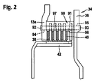
図2に、図1に示した組立て式のプレートキャリア34を断面図にして詳細に示す。プレートキャリア34はフランジ部分13a、キャリアディスク36及びフランジ部分13aとキャリアディスク36との軸線方向の間に配置された、周方向に亘って分配された接合エレメント90から形成される。図示の実施の形態においては、接合エレメント90はあらかじめ曲げられた金属薄板部分91から形成されている。金属薄板部分91は軸線方向に延在しているリベットピン92,93を有しており、これらのリベットピン92,93は、フランジ部分13a若しくはキャリアディスク36における対応する開口94,95を通って案内されており、外側から上述のフランジ部分13a若しくはキャリアディスク36に対してリベット留めされている。周方向を向いている金属薄板部分91の端部は歯面96を形成するために、半径方向内側にエッジ付けされているか又は折り曲げられている。これにより金属薄板部分91の横断面において、プレート38が懸架されている、歯面輪郭が形成される。プレート38は懸架のために相補的な外側輪郭を有している。その結果、プレート38はプレートキャリア34においてセンタリングされており、プレートキャリア34に加わるトルクはプレート38に伝達される。出力側のプレートキャリア42に相対回動不能にかつ軸線方向に制限されて移動可能に懸架されている摩擦プレート40とプレート38は交互に積層されている。
FIG. 2 is a detailed sectional view of the assembly-
図3に、プレートキャリア35aの形式において、図1の深絞り加工されたプレートキャリア35に対して択一的な形態を組み立てた状態において示す。プレートキャリア35aは図2の接合エレメント90と同一に形成された接合エレメント98を有している。この接合エレメント98は端部プレート72aとキャリアディスク36aとの間においてリベット留めされている。さらに図3に、軸線方向に伸ばされたピン86を備えた接合エレメント90aを示す。この接合エレメント90aは、例えば複数の周方向位置において図2の接合エレメント90の代わりを担い、これによりプレートキャリア34(図1)の摩擦装置85への係合が可能になる。これにより、ピン86は摩擦リング87をクラッチ装置のケーシング8(図1)に対して周方向に連行するので、摩擦装置を制御する。
FIG. 3 shows an alternative form of the
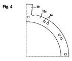
図4に、ねじり振動減衰器12(図1)のエネルギ貯蔵体11のための連行体19と、図2のリベットピン92を介して接合エレメント90を収容するための開口94とを備えたフランジ部分13aの一部分を示す。開口94の横断面は多角形であり、本実施の形態においては、リベットピン92(図1)の方形の横断面に対して相補的である方形である。同様に各接合エレメント90(図2)は、図示の実施の形態においては、隣り合う2つのリベットピンを有しているので、接合エレメントごとに夫々、隣り合う少なくとも2つの開口94が設けられている。
FIG. 4 shows a flange with an
図5には、図1のプレート38と類似のプレート38aの一部分を示す。このプレート38aは、例えば鋼から製造されている。図1のクラッチ装置1の実施の形態に対してプレート38aは、半径方向外側の湿式クラッチ28のプレートキャリア34の接合エレメント90,90a及び/又は半径方向内側の湿式クラッチ29のプレートキャリア35の接合エレメント98とは異なる、段付きピン99から形成されている接合エレメント90bに懸架されている。さらにプレート38aには段付きピン99の数だけ、周方向に亘って分配された円弧状の切欠き100が設けられている。これによりプレート38aはプレートキャリア(図示せず)において段付きピン99を介してセンタリングされかつ連行される。プレート38aの接触面における、切欠き100aにより提供される図1〜4の接合エレメントに比べて小さい段付きピン99の接触面により、上述の接合エレメントの数と比べて段付きピン99の数は多くなっていて、図示の実施の形態においては24個である。
FIG. 5 shows a portion of a
図6に、図1〜4のプレート38の一部分を示す。プレート38には周方向に亘って分配された、接合エレメント90に対して相補的な切欠き100が設けられている。これらの切欠き100は夫々、半径方向外側に傾いて延びている接触面101を有している。これらの接触面101は金属薄板部分91の歯面96と共に周方向に形状接続を形成する。これによりプレート38の回動連行は接合エレメント90の回動加圧時にプレートキャリア(図示せず)により行われる。さらに、リベットピン92若しくはリベットピン93(図2)は、別方向から見た場合には、フランジ部分13aの開口94若しくはキャリアディスク36(図2,4)の開口95にリベット留めされている。
FIG. 6 shows a portion of the
図7〜9に、図1〜4において組み付けられた、つまりリベット留めされた状態において示されている接合エレメント90を、まだリベット留めされていな状態において3つの方向から示す。打抜き成形及び予め成形された金属薄板91から形成されている接合エレメント90は端面側の端部に夫々、リベット留めするための少なくとも2つのリベットピン92,93を有している。これらのリベットピン92,93は横断面において有利に、また上述のように方形に形成されている。本実施の形態においては、リベットピン92,93は平坦なベース面102から軸線方向に拡張されていて、ベース面102に対して歯面96が角度付けされて形成されている。
FIGS. 7 to 9 show the joining
図10〜12に、リベットピン92a,93aに比べて夫々拡幅されたリベットピン103,104によってリベット留めされた状態における、図7〜9に示した接合エレメント90に対して択一的な接合エレメント90cの実施の形態を3つの方向から見て示す。図7〜9の接合エレメント90とは異なり、リベットピン92a,93aは歯面96に配置されているので、比較的大きな間隔を互いに夫々有している。この広幅な間隔により、接合エレメント90cのフランジ部分13a若しくはキャリアディスク36における固定は高い安定性を持って達成することができる。
10 to 12 are alternative joining elements to the joining
図13に、図1〜3の接合エレメント90aをリベット留めした状態において示す。図1〜3の摩擦装置85の加圧及び制御のためのピン86は、歯面96から軸線方向に拡張されている。
FIG. 13 shows the joining
図14及び図15に、両側に配置されたリベットピン92b,93bによってリベット留めされていない状態若しくはリベット留めされた状態における図5の段付きピン99、及びリベット留めされた状態におけるリベットヘッド103a,104aを示す。この段付きピン99は、有利には切削加工されるので、リベットピン92b,93bは横断面において円形に形成されている。
14 and 15, the stepped
1 クラッチ装置、 2 回転軸線、 6 ケーシング部分、 7 ケーシング部分、 8 ケーシング、 11 エネルギ貯蔵体、 12 ねじり振動減衰器、 13 入力部分、 13a フランジ部分、 14 すくい管、 16 環状フランジ部分、 17 連行体、 18 連行体、 19 連行体、 20 クランクシャフト、 21 駆動金属薄板、 22 伝動装置ケーシング、 23 転がり軸受、 24 軸線方向の突設部、 25 歯付きリム、 26 シールディスク、 27 シール、 28 湿式クラッチ、 29 湿式クラッチ、 30 円弧ばね、 31 円弧ばね、 32 段部、 33 磨耗保護シェル、 34 プレートキャリア、 35 プレートキャリア、 35a プレートキャリア、 36 キャリアディスク、 37 クラッチボス、 38 プレート、 38a プレート、 39 プレート、 40 摩擦プレート、 41 摩擦プレート、 42 プレートキャリア、 43 プレートキャリア、 44 ボス、 45 ボス、 45a エネルギ貯蔵体、 45b 固定ディスク、 46 歯列、 47 歯列、 48 伝動装置入力軸、 49 伝動装置入力軸、 50 ねじり振動吸振器、 51 遠心力振り子、 52 調速機おもり、 53 転がり軸受、 54 転がり軸受、 55 転がり軸受、 56 スラストワッシャ、 57 スラストワッシャ、 58 キャリア部分、 59 潤滑油溝、 60 転がり軸受、 61 転がり軸受、 62 シール金属薄板、 63 段部、 64 固定リング、 65 スラストワッシャ、 66 キャリア部分、 67 シムプレート、 68 スラストワッシャ、 69 ピストン、 70 ピストン、 71 端部プレート、 72 端部プレート、 72a 端部プレート、 73 回動導入器、 74 回動導入器、 75 供給管路、 76 供給管路、 77 圧力室、 78 圧力室、 79 エネルギ貯蔵体、 80 エネルギ貯蔵体、 81 供給管路、 82 供給管路、 83 ガイドピン、 84 排出管路、 85 摩擦装置、 86 ピン、 87 摩擦リング、 88 保持リング、 89 エネルギ貯蔵体、 90 接合エレメント、 90a 接合エレメント、 90b 接合エレメント、 90c 接合エレメント、 91 金属薄板部分、 92 リベットピン、 92a リベットピン、 92b リベットピン、 93 リベットピン、 93b リベットピン、 94 開口、 95 開口、 96 歯面、 97 外側輪郭、 98 接合エレメント、 99 段付きピン、 100 切欠き、 100a 切欠き、 101 接触面、 102 ベース面、 103 リベットヘッド、 103a リベットヘッド、 104 リベットヘッド、 104a リベットヘッド DESCRIPTION OF SYMBOLS 1 Clutch apparatus, 2 Rotating axis, 6 Casing part, 7 Casing part, 8 Casing, 11 Energy storage body, 12 Torsional vibration attenuator, 13 Input part, 13a Flange part, 14 Rake pipe, 16 Annular flange part, 17 Entrainment body , 18 entrained body, 19 entrained body, 20 crankshaft, 21 drive metal thin plate, 22 transmission device casing, 23 rolling bearing, 24 projecting portion in axial direction, 25 rim with teeth, 26 seal disc, 27 seal, 28 wet clutch 29 wet clutch, 30 arc spring, 31 arc spring, 32 step, 33 wear protection shell, 34 plate carrier, 35 plate carrier, 35a plate carrier, 36 carrier disk, 37 clutch boss, 8 plate, 38a plate, 39 plate, 40 friction plate, 41 friction plate, 42 plate carrier, 43 plate carrier, 44 boss, 45 boss, 45a energy storage, 45b fixed disk, 46 tooth row, 47 tooth row, 48 transmission Device input shaft, 49 Transmission device input shaft, 50 Torsional vibration absorber, 51 Centrifugal pendulum, 52 Speed governor weight, 53 Rolling bearing, 54 Rolling bearing, 55 Rolling bearing, 56 Thrust washer, 57 Thrust washer, 58 Carrier part 59, lubricating oil groove, 60 rolling bearing, 61 rolling bearing, 62 seal metal thin plate, 63 stepped portion, 64 fixing ring, 65 thrust washer, 66 carrier part, 67 shim plate, 68 thrust washer 70 piston, 70 piston, 71 end plate, 72 end plate, 72a end plate, 73 rotation introducer, 74 rotation introducer, 75 supply line, 76 supply line, 77 pressure chamber, 78 Pressure chamber, 79 energy storage, 80 energy storage, 81 supply line, 82 supply line, 83 guide pin, 84 discharge line, 85 friction device, 86 pin, 87 friction ring, 88 retaining ring, 89 energy storage Body, 90 joining element, 90a joining element, 90b joining element, 90c joining element, 91 metal thin plate part, 92 rivet pin, 92a rivet pin, 92b rivet pin, 93 rivet pin, 93b rivet pin, 94 opening, 95 opening, 96Tooth surface, 97 outer contour, 98 joint element, 99 stepped pin, 100 notch, 100a notch, 101 contact surface, 102 base surface, 103 rivet head, 103a rivet head, 104 rivet head, 104a rivet head
Claims (9)
半径方向に重畳して配置されていて、入力側及び出力側のプレートキャリア(34,35,35a,42,43)に取り付けられ、軸線方向に交互に配置されているプレート(38,38a,39)及び摩擦プレート(40,41)を有する、前記駆動ユニットによって駆動されるケーシング(8)内に配置されている少なくとも1つの湿式クラッチ(28,29)を備えている、パワートレインのためのクラッチ装置において、
前記入力側のプレートキャリア(34,35)はクラッチボス(37)に不動に取り付けられているキャリアディスク(36)に不動に接合されており、前記キャリアディスク(36)にねじり振動吸振器(50)が配置されており、
前記ねじり振動吸振器(50)は遠心力振り子(51)であることを特徴とする、パワートレインのためのクラッチ装置。 A clutch device (1) for a power train comprising a drive unit and a transmission device arranged downstream of the drive unit,
Plates (38, 38a, 39) that are arranged in the radial direction, are attached to the input and output plate carriers (34, 35, 35a, 42, 43), and are alternately arranged in the axial direction. And at least one wet clutch (28, 29) arranged in a casing (8) driven by the drive unit, having a friction plate (40, 41) In the device
The plate carrier (34, 35) on the input side is fixedly joined to a carrier disk (36) fixedly attached to a clutch boss (37), and a torsional vibration absorber (50) is attached to the carrier disk (36). ) Is placed ,
The clutch device for a power train, wherein the torsional vibration absorber (50) is a centrifugal pendulum (51) .
Applications Claiming Priority (3)
| Application Number | Priority Date | Filing Date | Title |
|---|---|---|---|
| DE102009005075 | 2009-01-19 | ||
| DE102009005075.2 | 2009-01-19 | ||
| PCT/DE2009/001810 WO2010081455A1 (en) | 2009-01-19 | 2009-12-22 | Clutch unit |
Publications (2)
| Publication Number | Publication Date |
|---|---|
| JP2012515308A JP2012515308A (en) | 2012-07-05 |
| JP5606451B2 true JP5606451B2 (en) | 2014-10-15 |
Family
ID=42027604
Family Applications (1)
| Application Number | Title | Priority Date | Filing Date |
|---|---|---|---|
| JP2011545623A Active JP5606451B2 (en) | 2009-01-19 | 2009-12-22 | Clutch device |
Country Status (6)
| Country | Link |
|---|---|
| US (1) | US8235192B2 (en) |
| EP (1) | EP2387673B2 (en) |
| JP (1) | JP5606451B2 (en) |
| CN (1) | CN102282382B (en) |
| DE (2) | DE112009003886A5 (en) |
| WO (1) | WO2010081455A1 (en) |
Families Citing this family (17)
| Publication number | Priority date | Publication date | Assignee | Title |
|---|---|---|---|---|
| DE102010018774B4 (en) * | 2009-05-06 | 2020-06-18 | Schaeffler Technologies AG & Co. KG | Double clutch with torsional vibration damper |
| WO2012013173A1 (en) * | 2010-07-29 | 2012-02-02 | Schaeffler Technologies Gmbh & Co. Kg | Clutch device |
| CN103797262A (en) | 2011-07-15 | 2014-05-14 | 舍弗勒技术有限两合公司 | Clutch |
| KR102073315B1 (en) * | 2012-03-16 | 2020-02-03 | 섀플러 테크놀로지스 아게 운트 코. 카게 | Friction clutch with centrifugal-force pendulum |
| US9541139B2 (en) | 2012-12-17 | 2017-01-10 | Schaeffler Technologies AG & Co. KG | Clutch |
| DE112014003386A5 (en) * | 2013-07-25 | 2016-04-21 | Schaeffler Technologies AG & Co. KG | Powertrain for a motor vehicle |
| DE112015001087A5 (en) * | 2014-03-05 | 2017-02-09 | Schaeffler Technologies AG & Co. KG | Torque transfer device |
| JP2017525914A (en) * | 2014-08-29 | 2017-09-07 | シェフラー テクノロジーズ アー・ゲー ウント コー. カー・ゲーSchaeffler Technologies AG & Co. KG | Dual clutch |
| FR3027077B1 (en) * | 2014-10-09 | 2018-01-26 | Valeo Embrayages | TRANSMISSION SYSTEM COMPRISING A WET DOUBLE CLUTCH MECHANISM |
| DE102015215897A1 (en) * | 2015-08-20 | 2017-02-23 | Schaeffler Technologies AG & Co. KG | Coupling device for hybrid drive |
| DE102017206227A1 (en) * | 2017-04-11 | 2018-10-11 | Zf Friedrichshafen Ag | Clutch assembly, dual clutch transmission assembly and motor vehicle |
| AT520016B1 (en) * | 2017-04-21 | 2019-02-15 | Miba Frictec Gmbh | plate carrier |
| CN107504092B (en) * | 2017-09-30 | 2024-04-16 | 中国第一汽车股份有限公司 | Sliding support piece and push disc assembly |
| DE102018104652A1 (en) * | 2018-03-01 | 2019-09-05 | Schaeffler Technologies AG & Co. KG | Production method of a corrugated spring washer for a centrifugal pendulum device; Centrifugal pendulum device; Clutch disc and drive train |
| WO2020164650A1 (en) * | 2019-02-13 | 2020-08-20 | Schaeffler Technologies AG & Co. KG | Clutch device comprising a fastening unit, which has a clamping element, between a torsional vibration damper and a disconnect clutch |
| DE102019112602A1 (en) * | 2019-05-14 | 2020-11-19 | Schaeffler Technologies AG & Co. KG | Coupling device, hybrid module and drive arrangement for a motor vehicle |
| WO2022207253A1 (en) * | 2021-03-29 | 2022-10-06 | Magna Pt B.V. & Co. Kg | Multi-unit multi-plate clutch arrangement having a bearing arrangement, and method for assembling a multi-unit multi-plate clutch |
Family Cites Families (20)
| Publication number | Priority date | Publication date | Assignee | Title |
|---|---|---|---|---|
| US2080395A (en) * | 1931-03-02 | 1937-05-18 | Midland Steel Prod Co | Brake drum and backing plate combination |
| FR2682439A1 (en) * | 1991-10-09 | 1993-04-16 | Carbone Ind | CLUTCH WITH STRUCTURAL DISCS, PARTICULARLY CARBON-CARBON. |
| JPH0592543U (en) † | 1992-05-15 | 1993-12-17 | 株式会社フジユニバンス | Clutch device |
| US5295411A (en) † | 1993-06-22 | 1994-03-22 | Speckhart Frank H | Torsional vibration absorber system |
| JP2606292Y2 (en) * | 1993-08-18 | 2000-10-10 | ヴァレオユニシアトランスミッション株式会社 | Flywheel |
| DE19804227B4 (en) † | 1998-02-04 | 2006-03-09 | Zf Sachs Ag | Lock-up clutch with a balancing mass on the torsional vibration damper |
| DE10034730B4 (en) * | 1999-09-30 | 2010-10-14 | Zf Sachs Ag | Multiple coupling device, possibly in combination with a torsional vibration damper assembly and / or an electric machine |
| DE10005548A1 (en) * | 2000-02-09 | 2001-08-16 | Mannesmann Sachs Ag | Friction clutch or coupling including flywheel and drive shaft also housing arrangement and pressure plate with diaphragm spring acting on pressure plate and disengagement power transmission acting against this |
| JP4797176B2 (en) † | 2001-06-12 | 2011-10-19 | シェフラー テクノロジーズ ゲゼルシャフト ミット ベシュレンクテル ハフツング ウント コンパニー コマンディートゲゼルシャフト | Torque transmission device |
| DE10310831A1 (en) | 2002-04-10 | 2003-11-06 | Luk Lamellen & Kupplungsbau | Vehicle drive train, includes divided flywheel with relatively-rotating weights between crank shaft and input to gearbox |
| DE10236752A1 (en) † | 2002-08-10 | 2004-02-19 | Daimlerchrysler Ag | Motor vehicle drive train, has spring-mass damper system in parallel with drive train interacting with torsional vibrations with energy exchange with drive train between start-up element, output shaft |
| JP2005098446A (en) * | 2003-09-26 | 2005-04-14 | Aisin Seiki Co Ltd | Damper device and clutch device |
| ATE419477T1 (en) * | 2004-06-21 | 2009-01-15 | Luk Lamellen & Kupplungsbau | TORQUE TRANSMISSION DEVICE |
| DE102005027610A1 (en) | 2004-06-21 | 2005-12-29 | Luk Lamellen Und Kupplungsbau Beteiligungs Kg | Torque transmission system for drive train of vehicle, comprising dual clutch with input shaft of transmission unit coupled with crankshaft |
| DE102006026373A1 (en) † | 2005-07-01 | 2007-01-04 | Luk Lamellen Und Kupplungsbau Beteiligungs Kg | Torque transmission equipment for use in motor vehicle drive train, radially and flexibly engages outer peripheral region of clutch cover against transmission housing such that initial biasing force of equipment reduces to zero |
| CN101300435B (en) † | 2005-11-04 | 2011-11-23 | 博格华纳公司 | Torsional-vibration damper connected to a crankshaft and a combination of a torsional-vibration damper and a clutch |
| WO2007079714A1 (en) † | 2006-01-12 | 2007-07-19 | Luk Lamellen Und Kupplungsbau Beteiligungs Kg | Torque converter with a lockup clutch between two dampers |
| DE502006007921D1 (en) * | 2006-07-28 | 2010-11-04 | Hoerbiger & Co | Disk carrier of a friction clutch |
| WO2009152800A1 (en) * | 2008-06-16 | 2009-12-23 | Luk Lamellen Und Kupplungsbau Beteiligungs Kg | Double clutch |
| CN102575722B (en) * | 2009-11-20 | 2019-05-28 | 舍弗勒技术股份两合公司 | Clutch apparatus |
-
2009
- 2009-12-22 DE DE112009003886T patent/DE112009003886A5/en not_active Ceased
- 2009-12-22 CN CN200980154965.3A patent/CN102282382B/en active Active
- 2009-12-22 WO PCT/DE2009/001810 patent/WO2010081455A1/en active Application Filing
- 2009-12-22 JP JP2011545623A patent/JP5606451B2/en active Active
- 2009-12-22 DE DE102009059943A patent/DE102009059943A1/en not_active Withdrawn
- 2009-12-22 EP EP09806172.4A patent/EP2387673B2/en active Active
-
2011
- 2011-07-19 US US13/185,763 patent/US8235192B2/en not_active Expired - Fee Related
Also Published As
| Publication number | Publication date |
|---|---|
| WO2010081455A1 (en) | 2010-07-22 |
| EP2387673A1 (en) | 2011-11-23 |
| DE102009059943A1 (en) | 2010-07-22 |
| JP2012515308A (en) | 2012-07-05 |
| US20110272233A1 (en) | 2011-11-10 |
| EP2387673B1 (en) | 2013-10-16 |
| DE112009003886A5 (en) | 2012-05-31 |
| US8235192B2 (en) | 2012-08-07 |
| EP2387673B2 (en) | 2021-12-29 |
| CN102282382A (en) | 2011-12-14 |
| CN102282382B (en) | 2014-12-10 |
Similar Documents
| Publication | Publication Date | Title |
|---|---|---|
| JP5606451B2 (en) | Clutch device | |
| KR102490875B1 (en) | torque transmission assembly | |
| WO2011122130A1 (en) | Fluid transmission device | |
| JP6626506B2 (en) | Fluid dynamic torque coupling with turbine-piston lockup clutch and associated method | |
| CN108350981B (en) | Torsional vibration damper with series connected inner and outer elastic damping members for a hydrokinetic torque coupling device | |
| JP2017075694A (en) | Torque transmission device of automobile | |
| KR20080065646A (en) | Multi-plate clutch and hydrodynamic torque converter device having said multi-plate clutch | |
| WO2016087200A1 (en) | Torque converter and hydrokinetic torque coupling device having core lockup clutch, and related methods | |
| US6193037B1 (en) | Hydrodynamic torque converter | |
| JP2017062029A (en) | Torsional damping device for motor vehicle transmission system | |
| US6264018B1 (en) | Lockup device of a torque converter | |
| KR101377254B1 (en) | Torque converter for vehicle | |
| KR101866035B1 (en) | Damper of Toque Convertor For Vehicle | |
| US5682972A (en) | Torsional vibration dampening device | |
| JPH07502325A (en) | Dampers and bypass clutches for fluid torque converters | |
| US6099434A (en) | Torsional vibration damper with an axial securing device | |
| JP7014775B2 (en) | Automotive clutch assembly with shock absorber to facilitate clutch engagement | |
| KR101405448B1 (en) | Torque converter for vehicle | |
| US20180202514A1 (en) | Torsional vibration damper for hydrodynamic torque converter, and torque converter including the same | |
| CN106468341B (en) | Torque transmission device | |
| KR20140009849A (en) | Torque convertor for vehicle | |
| CN107923480B (en) | Centrifugal force pendulum and hydrodynamic torque converter with a centrifugal force pendulum | |
| CN106468326B (en) | Centrifugal force pendulum and hydrodynamic torque converter with a centrifugal force pendulum | |
| KR101878199B1 (en) | Torque Converter for Vehicle | |
| KR101794907B1 (en) | The planetary gear as a semi-resonant torsional vibration damper is equipped with a torque converter |
Legal Events
| Date | Code | Title | Description |
|---|---|---|---|
| A621 | Written request for application examination |
Free format text: JAPANESE INTERMEDIATE CODE: A621 Effective date: 20121219 |
|
| A977 | Report on retrieval |
Free format text: JAPANESE INTERMEDIATE CODE: A971007 Effective date: 20131108 |
|
| A131 | Notification of reasons for refusal |
Free format text: JAPANESE INTERMEDIATE CODE: A131 Effective date: 20131216 |
|
| A521 | Request for written amendment filed |
Free format text: JAPANESE INTERMEDIATE CODE: A523 Effective date: 20140314 |
|
| TRDD | Decision of grant or rejection written | ||
| A01 | Written decision to grant a patent or to grant a registration (utility model) |
Free format text: JAPANESE INTERMEDIATE CODE: A01 Effective date: 20140728 |
|
| A61 | First payment of annual fees (during grant procedure) |
Free format text: JAPANESE INTERMEDIATE CODE: A61 Effective date: 20140826 |
|
| R150 | Certificate of patent or registration of utility model |
Ref document number: 5606451 Country of ref document: JP Free format text: JAPANESE INTERMEDIATE CODE: R150 |
|
| S111 | Request for change of ownership or part of ownership |
Free format text: JAPANESE INTERMEDIATE CODE: R313111 |
|
| R350 | Written notification of registration of transfer |
Free format text: JAPANESE INTERMEDIATE CODE: R350 |
|
| R250 | Receipt of annual fees |
Free format text: JAPANESE INTERMEDIATE CODE: R250 |
|
| R250 | Receipt of annual fees |
Free format text: JAPANESE INTERMEDIATE CODE: R250 |
|
| R250 | Receipt of annual fees |
Free format text: JAPANESE INTERMEDIATE CODE: R250 |
|
| R250 | Receipt of annual fees |
Free format text: JAPANESE INTERMEDIATE CODE: R250 |
|
| R250 | Receipt of annual fees |
Free format text: JAPANESE INTERMEDIATE CODE: R250 |
|
| R250 | Receipt of annual fees |
Free format text: JAPANESE INTERMEDIATE CODE: R250 |
|
| R250 | Receipt of annual fees |
Free format text: JAPANESE INTERMEDIATE CODE: R250 |