JP5605934B2 - VEHICLE RECORDING DEVICE HAVING COMMUNICATION FUNCTION AND VEHICLE INFORMATION MANAGEMENT DEVICE HAVING COMMUNICATION FUNCTION - Google Patents
VEHICLE RECORDING DEVICE HAVING COMMUNICATION FUNCTION AND VEHICLE INFORMATION MANAGEMENT DEVICE HAVING COMMUNICATION FUNCTION Download PDFInfo
- Publication number
- JP5605934B2 JP5605934B2 JP2009101653A JP2009101653A JP5605934B2 JP 5605934 B2 JP5605934 B2 JP 5605934B2 JP 2009101653 A JP2009101653 A JP 2009101653A JP 2009101653 A JP2009101653 A JP 2009101653A JP 5605934 B2 JP5605934 B2 JP 5605934B2
- Authority
- JP
- Japan
- Prior art keywords
- vehicle
- information
- vehicle information
- unit
- vehicles
- Prior art date
- Legal status (The legal status is an assumption and is not a legal conclusion. Google has not performed a legal analysis and makes no representation as to the accuracy of the status listed.)
- Expired - Fee Related
Links
Images


Classifications
-
- Y02T10/7077—
Description
本発明は、ドライブレコーダ等の車両の記録装置に関し、さらに詳しくは通信機能を備えた車両の記録装置およびこれと連携する車両情報管理装置に関する。 The present invention relates to a vehicle recording device such as a drive recorder, and more particularly to a vehicle recording device having a communication function and a vehicle information management device linked therewith.
近年、車両走行の安全のために種々の提案がなされている。走行状況や運転状況を記録することによって事故等の際の証拠にするためのドライブレコーダはその例である。また、単に証拠として過去の記録を残すだけでなく、将来への前向きの改善を行うため提案もなされている。例えば運転者の運転技術を効率的に診断できるシステム(特許文献1)や、乗務員に対して的確な運転指導および運転評価を行うことができるドライブレコーダ(特許文献2)が提案されている。一方、通信機能を有する車両の記録装置も提案されており、例えば車両における種々の動作履歴に関する履歴情報を暗号化して送信することにより情報の改竄等を防止することができる車両履歴情報管理システム(特許文献3)が提案されている。 In recent years, various proposals have been made for the safety of vehicle travel. An example of this is a drive recorder for recording the driving situation and driving situation as evidence in the event of an accident. Proposals have also been made to make positive improvements to the future, not just leaving records of the past as evidence. For example, a system (Patent Document 1) capable of efficiently diagnosing a driver's driving technology and a drive recorder (Patent Document 2) capable of performing accurate driving guidance and driving evaluation for a crew member have been proposed. On the other hand, a vehicle recording apparatus having a communication function has also been proposed. For example, a vehicle history information management system that can prevent falsification of information by encrypting and transmitting history information about various operation histories in the vehicle ( Patent Document 3) has been proposed.
しかしながら、本来記録には監視と管理の側面があり、車両の記録装置搭載が一般に広く受け容れられ、普及していくためにはまだ種々検討すべき課題が多い。 However, recording originally has monitoring and management aspects, and mounting of a recording device on a vehicle is generally widely accepted, and there are still many problems to be examined in order to spread.
本発明の課題は、上記に鑑み、一般に広く受け容れやすい車両の記録装置およびこれを促進する車両情報管理装置を提供することにある。 In view of the above, an object of the present invention is to provide a vehicle recording apparatus that is generally widely accepted and a vehicle information management apparatus that promotes the recording apparatus.
上記課題を解決するため、本発明は、車両情報取得部と、車両情報を外部に送信する送信部と、多数の車両から集結する車両情報の統計情報を受信する受信部と、受信した統計情報と車両情報取得部が取得した車両情報を比較する制御部とを有する通信機能を備えた車両の記録装置を提供する。これによって、客観的な統計情報との関係で自車の情報を把握することができ比較結果に対する関心が高まるとともに比較結果が受け容れられやすくなる。 In order to solve the above problems, the present invention provides a vehicle information acquisition unit, a transmission unit that transmits vehicle information to the outside, a reception unit that receives statistical information of vehicle information gathered from a large number of vehicles, and received statistical information There is provided a vehicle recording apparatus having a communication function including a control unit that compares vehicle information acquired by the vehicle information acquisition unit. As a result, the vehicle information can be grasped in relation to the objective statistical information, and the interest in the comparison result is increased and the comparison result is easily accepted.
本発明の具体的な特徴によれば、情報取得部は燃費計を含むとともに、統計情報は多数の車両から集結する燃費情報の平均値を含む。これによって、自社の燃費の位置づけを平均値との関係で客観的に知ることができ、コストへの関心に基づいて環境に優しい運転を心がけることができる。 According to a specific feature of the present invention, the information acquisition unit includes a fuel consumption meter, and the statistical information includes an average value of fuel consumption information gathered from a large number of vehicles. This makes it possible to objectively know the position of the company's fuel economy in relation to the average value, and to keep environmentally friendly driving based on the interest in cost.
本発明の他の具体的な特徴によれば、車両情報取得部は燃費計を含むとともに、統計情報は多数の車両から集結する燃費情報の分布状態を示すものを含む。これによって、自社の燃費の位置づけを分布の中の位置づけとして客観的に知ることができ、コストへの関心に基づいて環境に優しい運転を心がけることができる。 According to another specific feature of the present invention, the vehicle information acquisition unit includes a fuel consumption meter, and the statistical information includes information indicating a distribution state of the fuel consumption information gathered from a large number of vehicles. As a result, the position of the company's fuel consumption can be objectively known as the position in the distribution, and environmentally friendly driving can be attempted based on the interest in cost.
本発明の他の具体的な特徴によれば、統計情報に用いられる多数の車両のデータは車種を問わない。これによって、車種を問わない絶対的な統計データの中での自車の位置づけを客観的に知ることができる。 According to another specific feature of the present invention, the data of a large number of vehicles used for the statistical information may be of any vehicle type. This makes it possible to objectively know the position of the vehicle in absolute statistical data regardless of the vehicle type.
本発明の他の具体的な特徴によれば、統計情報に用いられる多数の車両のデータは同一車種に限定される。この場合は、同一条件にある同一車種内での自車の位置づけを客観的に知ることができ、この場合は自車の位置づけが低ければすべて自己責任となるので、結果を厳粛に受け止めることができる。 According to another specific feature of the present invention, data of a large number of vehicles used for statistical information is limited to the same vehicle type. In this case, it is possible to objectively know the position of the vehicle within the same vehicle type under the same conditions. In this case, if the position of the vehicle is low, it will be self-responsibility. it can.
本発明の他の具体的な特徴によれば、車両情報取得部は燃費計を含むとともに、統計情報は多数の車両から集結する燃費情報の車種別平均値を含む。この場合は、自車の位置づけに関する情報ではないが、統計作りのために情報提供することにより、客観的な実績としての車種別平均燃費を知ることができ、性能としての自車の評価と将来車種変更の情報として活用することができる。 According to another specific feature of the present invention, the vehicle information acquisition unit includes a fuel consumption meter, and the statistical information includes a vehicle type average value of the fuel consumption information gathered from a large number of vehicles. In this case, it is not information about the positioning of the vehicle, but by providing information for the purpose of making statistics, it is possible to know the average fuel consumption by type as an objective performance, and to evaluate the vehicle's performance as a performance and the future It can be used as vehicle type change information.
本発明の他の具体的な特徴によれば、車両情報取得部は走行情報検知部および燃費計を含み、送信部は走行情報検知部が検知する特定の走行状態に関する燃費情報を送信するとともに、統計情報は多数の車両から集結する特定の走行状態に関する燃費情報の平均値を含む。これによって例えば、平地定速度走行状態、平地加速走行状態、平地減速走行状態、登坂状態、下坂状態、および発進時など特定の走行状態毎に燃費の平均値と自車の燃費の関係を知ることができ、運転操作改善の参考にすることができる。 According to another specific feature of the present invention, the vehicle information acquisition unit includes a travel information detection unit and a fuel consumption meter, and the transmission unit transmits fuel consumption information related to a specific travel state detected by the travel information detection unit, and The statistical information includes an average value of fuel consumption information related to a specific traveling state gathered from a large number of vehicles. By this, for example, knowing the relationship between the average value of fuel consumption and the fuel consumption of the vehicle for each specific driving state such as a flat ground constant speed driving state, a flat ground acceleration traveling state, a flat ground deceleration traveling state, an uphill state, a downhill state, and a start It can be used as a reference for improving driving operations.
本発明の他の具体的な特徴によれば、車両情報取得部は全走行中に占める平地定速走行状態比率の取得部を含むとともに、統計情報は多数の車両から集結する全走行中に占める平地定速走行状態比率の平均値を含む。これによって、燃費に影響する平地定速走行状態比率について世間平均と自車の状況とを客観的に比較でき、急加速や急停止の少ない環境に優しく安全な運転を自発的に心がけることができる。 According to another specific feature of the present invention, the vehicle information acquisition unit includes an acquisition unit of a flat land constant speed traveling state ratio that occupies during all traveling, and the statistical information occupies during all traveling that gathers from a large number of vehicles. Including the average value of the flat land constant speed running state ratio. This makes it possible to objectively compare the average of the world and the situation of the vehicle with respect to the ratio of constant-speed driving on flat terrain that affects fuel consumption, and can voluntarily strive for safe driving that is gentle to environments with few sudden accelerations or sudden stops. .
本発明の他の具体的な特徴によれば、車両情報取得部は車両操作データ記録部を含むとともに、統計情報は多数の車両から集結する車両操作データの平均値を含む。ここで車両操作データとは例えばブレーキ操作、アクセル操作、ハンドル操作の少なくとも一つの操作記録である。これによって、自分の運転操作を客観的に世間水準と比較することができ環境に優しく安全な運転を自発的に心がけることができる。 According to another specific feature of the present invention, the vehicle information acquisition unit includes a vehicle operation data recording unit, and the statistical information includes an average value of vehicle operation data collected from a number of vehicles. Here, the vehicle operation data is, for example, at least one operation record of a brake operation, an accelerator operation, and a steering wheel operation. As a result, it is possible to objectively compare one's driving operation with the world level, and to voluntarily try safe driving that is friendly to the environment.
本発明の他の具体的な特徴によれば、制御部による比較結果に基づいて告知を行う告知部が車両の記録装置に設けられる。これによって、上記のようにして制御部が比較する種々の情報の比較結果を必要に応じて知ることができる。 According to another specific feature of the present invention, a notification unit that makes a notification based on a comparison result by the control unit is provided in the recording device of the vehicle. As a result, it is possible to know, as necessary, the comparison results of various information that the control unit compares as described above.
本発明は上記のように外部との通信によって統計データを得るものである。従って本発明によれば、車両側における記録装置と併せ、このような車両の記録装置とともに用いられる外部の車両情報管理装置が提供される。 As described above, the present invention obtains statistical data by communication with the outside. Therefore, according to the present invention, an external vehicle information management device used with such a vehicle recording device is provided in addition to the recording device on the vehicle side.
本発明が提供する車両情報管理装置は、多数の車両から集結する車両情報を受信する受信部と、受信した車両情報に基づいて統計情報を作成する制御部と、制御部が作成した統計情報を多数の車両に送信する送信部とを有することを特徴とする。 The vehicle information management device provided by the present invention includes a receiving unit that receives vehicle information gathered from a large number of vehicles, a control unit that creates statistical information based on the received vehicle information, and statistical information created by the control unit. It has a transmission part which transmits to many vehicles.
本発明によれば、上記の車両情報管理装置に関しても種々の具体的な特徴が提案される。その内容は、車両の記録装置に関して上記に具体的に述べた種々の具体的な特徴に対応したものであり、車両の記録装置と連携して機能することができる。 According to the present invention, various specific features are also proposed for the vehicle information management device. The contents correspond to the various specific features specifically described above with respect to the vehicle recording device, and can function in cooperation with the vehicle recording device.
上記のように本発明によれば、統計データへの関心に絡めて情報を取得できるなど、運転者にとって受け容れやすい形の車両の記録装置が提供できる。 As described above, according to the present invention, it is possible to provide a vehicle recording apparatus that is easily accepted by the driver, such as being able to acquire information related to the interest in statistical data.
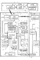
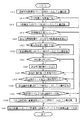
図1は、本発明の実施の形態に係るドライブレコーダシステムの第1実施例を示すブロック図である。本実施例のドライブレコーダシステムは、事故前後の情報を記録するドライブレコーダを備えたガソリンエンジン車または電気自動車またはガソリンエンジンとモーターを併用するいわゆるハイブリッドタ車のいずれかである車両2を中心とするものであるが、さらに信号機4、および給油/給電スタンド6と共同するシステムを構成している。
FIG. 1 is a block diagram showing a first example of the drive recorder system according to the embodiment of the present invention. The drive recorder system of the present embodiment is centered on a
車両2は、車両全体を制御するコンピュータからなる車両制御部8を有し、車両の運転者による操作部10の操作に応じて、車両機能部12を制御する。この車両制御部8の機能は記憶部14に格納されたソフトウエアによって実行される。記憶部14は、さらに両全体の制御に必要な種々のデータを一時的に格納する。また、車両制御部8は、表示部16を制御し、操作部10の操作に必要なGUI表示を行うとともに制御結果の表示を行う。なお、車両制御部8は時計部18を有し、種々の機能においてこの時計部8の時刻情報が利用される。また、後述のようにこの時計部18の時刻は外部の時刻情報により適宜正しい時刻に自動修正される。
The
GPS部20は、GPSシステムに基づいて衛星および最寄の放送局より車両2の絶対位置情報である緯度、経度、および高度の情報を得て車両制御部8に送る。カーナビゲーション機能部22は、車両制御部8経由で得られるGPS部20からの絶対位置情報を処理し、地図上での車両2の位置を表示部16に表示する。車両2は、さらに車両近距離通信部24を備えており、後述のように、信号機4および給油/給電スタンド6に接近したとき、これらとの間で電波または光により情報の授受を行う。
The
次にドライブレコーダに関する構成を、必要に応じ上記の構成とも関連づけて説明する。カメラ26およびマイク28には、車両が運行状態にあるとき常時車両前方等の画像および周囲の音が入力される。なお、運行状態とは実際に走行している場合だけでなく信号待ちで一時停車している状態など、車両の走行に伴って交通事故が発生する可能性のある状態全てを含む。この状況にあるかどうかをチェックするためにカメラ26で撮影された画像に基づく画像処理によって動体の有無が検知され、エンジンを停止しても、その後画像中に動体が検知されていない状態が所定時間続くことが確認されない限りカメラ26およびマイク28への画像および音の入力が継続される。
Next, a configuration related to the drive recorder will be described in association with the above configuration as necessary. The
車両制御部8は20秒程度の容量の不揮発性バッファメモリを備えており、カメラ26およびマイク28から入力された画像および音の情報を先入れ先出し(FIFO)で記憶する。つまり最新20秒の情報が常時上書き記憶され続ける。そして、加速度検知部30が衝突などによる大きな加速度変化を検知したときまたは操作部10により手動操作があったとき、カメラ26およびマイク28が破壊されずに情報入力が継続していれば、その時点からさらに10秒程度のバッファメモリへの記憶を続ける。これによってバッファメモリには、加速度変化の検知または手動操作の時点の前後それぞれ10秒程度の画像および音情報が最終的に保持される。この前後10秒程度の画像および音情報は、車両制御部8によって所定の処理が行われた後、デジタル圧縮動画情報として車両の異なる部分に設けられた第一記録部32および第二記録部34にそれぞれ記録されるよう構成する。第一記録部32および第二記録部34はそれぞれ不揮発メモリで構成され、事故等によってこれらの記憶部への給電が断たれても記録が保持される。第一記録部32および第二記録部34はそれぞれデジタル圧縮動画情報10件分の容量を持っており、FIFOで上書きされていく。
The
第一記録部32は、例えば車両前部に設けられるとともに、第二記録部34は、例えば車両後部に設けられ、これらに同じ情報を記録するよう構成することによって、事故により万一その一方が破壊されても他方が生き残って記録可能となることを期待している。また、記録済みの情報についても、少なくとも一方には残ることを期待している。なお、ドライブレコーダ機能の大半が破壊された場合でも、不揮発性バッファメモリさえ無事ならば、事故前20秒程度の記録が残されることになる。
The
ここで、第一記録部32および第二記録部34に画像及び音情報をそれぞれ記録する際に車両制御部8によって行われる処理について説明する。この処理は、通常の音声つきデジタル圧縮動画情報を作成する処理に加え、この音声つきデジタル圧縮動画情報の改ざんやすり替えを防止して証拠力を高めるとともに、証拠としての情報をより豊富にするための処理を含んでいる。
Here, processing performed by the
信号機4は、証拠情報を豊富にするための構成であって、信号機制御部36は赤・青・黄の信号灯38を制御している。そして、信号機近距離通信部40は交差する道路のどちら向きの信号灯が今どの色であるかの情報を信号機4近辺に発信している。この信号機近距離通信部40は、信号機システム通信部42から得られる車両情報通信システムからの渋滞情報などを信号機4近辺に発信するための構成を兼用したものである。従って、これらの情報は信号機4のある交差点近辺に車両2が存在すれば車両近距離通信部24によって受信され、車両制御部8に送られる。これによって車両2が交差点を通過中または信号待ち停車中に加速度変化の検知または手動操作があったときには、車両2の進行方向の信号灯38の状態が情報として取得できる。このようにして、カメラ26の画角の限界やカメラ26と信号灯38の同期が原因で信号灯38の状態がカメラ26の画像からは得られない場合であっても、加速度変化の検知または手動操作(以下その代表的な場合として「事故発生」と称する)に至るまでの信号灯38の状況を把握することができるようになる。方位検知部44は、事故発生の直前に車が向いていた方向を検出するもので、上記の信号機4からの情報との組合せで事故発生時に車両2に信号無視があったかどうかの証拠を提供するものである。
The
車両制御部8は、速度計46の速度情報を受け、これを不揮発性バッファメモリにおける20秒程度分の容量にFIFOで順次上書き記録していく。これによって、事故発生時の速度と制限速度との関係および事故発生前20秒程度の間のブレーキ操作履歴などを把握することが可能となる。このような事故発生時の速度情報やブレーキ操作履歴は、上記の事故発生時の進行方向の信号灯情報、時計18からの事故発生時刻情報、ならびにGPS部20からの事故発生地点情報とともに電子透かし処理部48に送られ、電子透かしデータとして扱われる。なお、ブレーキなどの操作情報は、上記のように速度情報から間接的に把握できる他、操作部10から直接車両操作部8に送ることもできるので、これらの操作情履歴も不揮発性バッファメモリにFIFOで順次上書き記録することもできる。
The
電子透かし処理部48にはバッファメモリに一時記憶されている事故発生前後それぞれ10秒程度の画像および音情報が送られ、上記の速度情報、ブレーキ操作履歴、信号灯情報、時刻情報、地点情報よりなる電子透かしデータが埋め込まれる。なお、この埋め込みの際には、記憶部14に保持されている電子透かし処理キー情報が設定されて用いられる。このようにして電子透かし処理キー情報を用いて電子透かしデータが埋め込まれた画像および音情報は、車両制御部8に戻されてデジタル圧縮され、それぞれ第一記録部32および第二記録部34に送られる。以上のように、事故発生前後それぞれ10秒程度の画像および音情報には電子透かし処理キー情報を用いて事故発生に関連する電子透かし情報が埋め込まれているので、画像情報および音情報を改ざんすることは困難となる。また、電子透かし情報自体もこれらを抽出することによって事故発生時点の証拠情報が豊富になる。
The digital
以上、ドライブレコーダ機能については、その制御が車両制御部8で行われるよう説明したが、全ての機能を車両制御部8に負担させる代わりに、ドライブレコーダ機能を担当する専用の制御部を別に設け、機能を分担させてもよい。この場合も、ドライブレコーダ専用制御部は車両制御部8と連携し、全体として上記に説明したような機能を実行する。
As described above, the drive recorder function is described as being controlled by the
また、万一の事故が起こったときにドライブレコーダに情報が記録されていないことを防ぎ、記録の信頼性を高めるため、上記のドライブレコーダ機能を達成する構成部分は車両2の所有者にはアクセスできない部分に納められており、車検等の際に資格のある者だけがアクセスできる。またカメラ26やマイク28と車両制御部8を結ぶケーブル等も車両2の所有者には見えない部分に納められる。ドライブレコーダ機能を車両2に後から追加する場合であっても、その取り付けは資格のある者に限られ、ケーブル等も車両2の所有者が勝手に取り外すことができないよう設置される。さらに、誤ってこれらのケーブルが切断される等してドライブレコーダ機能が損なわれたときには、車外表示部50がこれを車両2の外部に表示し、この表示が警察に発見されたときには交通違反となる。
In addition, in order to prevent information from being recorded on the drive recorder in the event of an accident and to improve the reliability of recording, the components that achieve the drive recorder function described above are It is stored in an inaccessible part and can only be accessed by qualified personnel during vehicle inspections. Further, a cable connecting the
一方で、車両2を始動させる毎にドライブレコーダ機能の初期チェックが行われ、正常である旨の表示を表示部16に行う。これに代えてアナウンスによりチェック結果が正常である旨を通知するようにしてもよく、また両者を併用してもよい。交通事故は本来起こってはならないことであり、安全運転者にとっては実際、何年も何事も起こらない可能性が高い。この間、ドライブレコーダが働く機会は一度もないことになるが、上記のように構成することにより、日常的に機能が正常であることが確認でき、万一の場合に情報が記録されないような事態を未然に防止できる。
On the other hand, every time the
給油/給電スタンド6は、給油または給電のためにスタンドに立ち寄った車両との交信を行うためのスタンド近距離通信部52を備えている。スタンド制御部54はスタンドシステム通信部56から車両2のID情報及び車両2に適用すべき最新の電子透かし処理キー情報を取得している。この最新の電子透かし処理キー情報はスタンド近距離通信部52と車両近距離通信部24の交信により車両2に伝えられ、車両制御部8経由で記憶部14に送られて旧い電子透かし処理キー情報を更新する。このような電子透かし処理キー情報の更新はドライブレコーダによる画像および音情報の改ざんやすり替えを防止するためのものであり、各車両の電子透かし処理キー情報の更新履歴はそれぞれドライブレコーダ管理センターに個別に登録されているので、万一電子透かし処理キー情報が漏洩したとしても、期限切れの電子透かし処理キーで作成したデジタル画像情報は真正の記録とは認められない。なお、この電子透かし処理キー情報の更新は信号機4から頻繁に行うよう構成してもよい。
The refueling / power supply stand 6 includes a stand short-
給油/給電部58は、給油/給電部ライン60を介して車両2の給油/給電部口62に給油/給電を行う。このとき、車両2が電気自動車またはハイブリッド車であった場合は、給油/給電部ライン60を介した電力線通信(PLC)により、電子透かし処理キー情報をスタンド制御部54から車両制御部8に伝達することができる。
The oil supply /
なお、上記のように本発明の第1実施例におけるドライブレコーダ情報は車両2の所有者自身が変更することができないものであるが、所有者がパスワードを入力することにより、車両制御部8のカードスロットに挿入したメモリカードにコピーして取り出しするのは自由である。従ってこのようにして取り出したデータを自身の携帯電話やパソコンで見ることは可能である。
Note that, as described above, the drive recorder information in the first embodiment of the present invention cannot be changed by the owner of the
また、図1では、車両2が給油/給電スタンド6との近距離通信によって電子透かし処理キー情報の更新を行う場合を図示しているが、このような電子透かし処理キー情報の更新はこのような場合に限るものではない。例えば、「給油/給電スタンド6」を「道路通行料自動徴収システム(ETC)6」と読替えるとともにその内部構成52、54および56における「スタンド」を「ETC」に読替えれば、ETC6を通過する毎に電子透かし処理キー情報の更新を行う形でも本発明が実施できることが理解できる。この場合、車両2における車両近距離通信部24とETC6におけるETC近距離通信部52が電子透かし処理キー情報の交信にも兼用されることになる。
FIG. 1 illustrates the case where the
なお、上記のETC6のように車両2との契約関係に基づいて近距離通信を行うよう構成され、個人情報管理がしっかりと行われているようなシステムの近距離通信部を兼用する場合は、さらに次のような情報交信を行うことも可能である。つまり、第一記録部32または第二記録部34に何らかのドライブレコーダ情報が記録されている場合にはこれが自動的に車両近距離通信部24からETC近距離通信部52に自動送信され、これがさらにETCシステム通信部56からETCの管理センターに転送されるよう構成することができる。但し、このような転送を自動的に行うかどうかは予め運転者の同意を得ることを条件とし、同意すれば高速道路料金を割り引く等のインセンティブをつける。これによって、運転者の同意の下にひき逃げや当て逃げの証拠がETCの管理センターに蓄積されることになるので、運転者の安全運転への自覚を高めることも可能となる。
In addition, when it is configured to perform near field communication based on the contractual relationship with the
図2は、図1の第1実施例における車両2の車両制御部8の機能を示す基本フローチャートである。このフローは車両2が走行可能状態になることによってスタートする。具体的には、ガソリンエンジン車の場合はイグニションのオン、ハイブリッド車や電気自動車では走行準備スイッチのオンによって走行可能状態となり、フローがスタートする。なお、走行可能状態とは実際に走行している状態も含む。フローがスタートすると、まずステップS2でドライブレコーダ機能を含む車両機能を初期チェックする。この処理は、チェック結果の表示またはアナウンスによる通知を含む。
FIG. 2 is a basic flowchart showing functions of the
次いでステップS4でカメラ26およびマイク28からの情報に基づき画像と音の記録が行われる。また、ステップS6では、その時点におけるGPS部20からのGPS情報、速度計46からの速度情報、方位検知部44からの進行方向情報、時計18からの時刻情報および操作部10よりの操作情報をそれぞれ取得してステップS8に至る。
Next, in step S4, an image and sound are recorded based on information from the
ステップS8では、車両近距離通信部24に信号機灯4からの信号灯情報が着信しているかどうかのチェックが行われる。そして車両が交差点に差しかかっていて信号灯情報の着信がある場合にはステップS10に進み、信号灯情報を取得してステップS12に移行する。なお、信号機4は車両2にとっての進行方向およびこれに直行する方向の両者についてそれぞれ信号灯38がどのような状態にあるかの情報を発信しており、ステップS10では、車両近距離通信部24により、これらの情報をすべてそのまま取得する。一方、車両が交差点に差しかかっていないか、または交差点にさしかかっていているが信号機に信号灯情報発信機能がなく、この結果信号等情報の着信がない場合には、ステップS8から直接ステップS12に移行する。
In step S8, it is checked whether signal light information from the
ステップS12では、ステップS4、ステップS6およびステップS10で得られる情報を車両制御部8内の不揮発性バッファメモリにおける20秒程度分の容量にFIFOで上書き記録する。その詳細は後述する。ステップS12においてその時点で得られた情報の記録が終わるとステップS14に移行し、車両近距離通信部24による通信相手が通信可能距離範囲に存在して近距離通信が可能かどうかのチェックが行われる。なお、ステップS14では、電力線通信(PLC)により通信が可能かどうかも併せてチェックしている。この場合の通信相手とは、例えば給油/給電スタンド6またはETC6であるが、信号機4についても信号灯情報受信以外の通信が可能であれば、この場合の通信相手に該当する。
In step S12, the information obtained in steps S4, S6, and S10 is overwritten and recorded by FIFO in the capacity of about 20 seconds in the nonvolatile buffer memory in the
ステップS14で近距離通信または電力線通信が可能と判断されたときはステップS16に進み、近距離通信または電力線通信による情報交信処理を行ってステップS18に移行する。この場合のステップS16での情報交信処理の内容は、具体的には電子透かし処理キー情報の更新情報の受信であるが、この他、既に述べたように第一記録部32または第二記録部34に記録されているドライブレコーダ情報の送信もステップS16での情報交信処理に該当する。これらの詳細は後述する。なお、ステップS14で近距離通信または電力線通信のいずれも可能ではないと判断されれば直接ステップS18に移行する。
When it is determined in step S14 that near field communication or power line communication is possible, the process proceeds to step S16, information communication processing by near field communication or power line communication is performed, and the process proceeds to step S18. In this case, the content of the information communication process in step S16 is specifically the reception of the update information of the digital watermark processing key information. In addition, as described above, the
ステップS18では、操作部10による手動操作または加速度検知部30による所定以上の加速度変化検知があったかどうかのチェックが行われる。ここで、所定以上の加速度変化とは正面衝突のような同一方向での急減速、衝突による進行方向の変化等の車両走行中の加速度変化が含まれるが、車両2自身が停止中であったとしても他車両に衝突された場合の衝撃なども含まれる。
In step S <b> 18, it is checked whether a manual operation by the
ステップS18で手動操作または所定以上の加速度変化が検出されたときはステップS20に進み、記憶部14から車両2として最新の電子透かし処理キーを読出す。そしてステップS22で種々の電子透かしデータを電子透かし処理キーに基づいて動画の画像/音情報に埋め込む電子透かし処理を行う。そしてステップS24に進み、電子透かしが埋め込まれた画像/音情報を圧縮し、第一記録部32および第二記録部34に記録する処理を行い、ステップ26に移行する。なお、ステップS18で手動操作および所定以上の加速度変化のいずれも検出されないときは直接ステップS26に移行する。上記のステップS22およびステップS24の詳細については、それぞれ後述する。
When a manual operation or a change in acceleration exceeding a predetermined value is detected in step S18, the process proceeds to step S20, and the latest digital watermark processing key is read from the
ステップS26では車両2が走行可能状態であるかどうかチェックし、該当すればステップS4に戻る。一方、イグニションのオフまたは走行準備スイッチのオフによって走行準備状態でなくなっているときはステップS28に進み、カメラ26で取得される画像に基づいて画像中に動体が含まれているどうかの検知を行う。そして動体が検知されれば、ステップS4に戻る。動体が検知されるということは、自分の動力はオフになっているが車両2が惰性または坂道下降によって走行している状態にあるか、または、車両2自身は停止しているが周囲を車両が走行していて車両2が道路の中にあることを意味し、車両2はまだ安全な状態にはないからである。
In step S26, it is checked whether or not the
一方、ステップ28で動体が検出されない場合はステップ30に進み、動体を検出しない状態が所定時間以上続いているかどうかをチェックする。そしてまだ所定時間に達していない場合はステップ4に戻る。事故直後の場合や、車両2が道路中に停止しているがたまたま周囲を車両が走行していない場合は、動体が検出されないことがあるからである。以上のようにして、ステップ26からステップ30のいずれかからステップ4に戻ったときには、ステップ4の画像/音記録からの処理が行われ、以下、ステップ30で所定時間以上動体が無検知で車両2が安全な場所に停止していると看做されるまではステップS4からステップS30が繰り返される。そして、画像/音情報ならびに所定情報の取得、およびそのFIFO記録が継続され、その間所定以上の加速度が検知される毎に電子透かしが埋め込まれた画像/音情報の圧縮データの記録が行われていく。一方、ステップS30で所定時間以上動体が無検知であることが検知されるとステップS32に進み、動画/音記録および諸情報取得を停止してフローを終了する。
On the other hand, if no moving object is detected in
図3は、図2のステップS22における電子透かし処理の詳細を示すフローチャートである。フローがスタートすると、ステップS42で記憶部14から車両2のIDデータを読み出す。このIDは後述のように、電子透かしデータとして使用されるとともに、現在車両2に適用されている電子透かし処理キーのバージョンを特定するデータとしても利用される。つまり、どのバージョンの電子透かし処理キーが現在車両2に適用されているかはドライブレコーダ管理センターに個別に登録されているので、読み出した車両2のIDを付加することにより、登録された真正の電子透かし処理キーによって電子透かしが埋め込まれた画像/音情報の圧縮データであることの証とすることができる。
FIG. 3 is a flowchart showing details of the digital watermark processing in step S22 of FIG. When the flow starts, the ID data of the
次いで、ステップS44では、図2のステップS20で読み出された電子透かし処理キーが電子透かし処理部48に設定される。次にステップS46では、加速度変化検知後に車両制御部8の不揮発性バッファメモリが破壊されず無事に残っているかどうかのチェックが行われる。そして無事ならばステップS48に進み、加速度変化検知時のGPS情報および時刻情報がバッファメモリから抽出される。さらにステップS50では、加速度変化検知時の進行方向情報をバッファメモリから抽出してステップS52に進む。
Next, in step S44, the digital watermark processing key read in step S20 of FIG. Next, in step S46, it is checked whether the nonvolatile buffer memory of the
ステップS52では、バッファメモリ中に信号灯情報が存在するかどうかチェックする。信号灯情報があるということは加速度変化検知時点近辺に車両2が交差点近辺にあったことを意味するのでステップS54に進み、加速度変化検知時までの信号灯情報を抽出する。そしてステップS56では、ステップS50で抽出された進行方向情報を参照して加速度変化検知時までの進行方向の信号灯情報を選別してステップS58に移行する。一方、ステップS52でバッファメモリ中に信号灯情報が存在しないと判断されたときは直接ステップS58に移行する。
In step S52, it is checked whether signal lamp information exists in the buffer memory. The presence of the signal light information means that the
ステップS58では、加速度変化検知時までのバッファメモリ内の全速度情報履歴が取り出され、ステップS60でこれらをもとにブレーキ操作の様子を分析してステップS62に進む。以上のようにステップS56およびステップS58の時点で取り出すバッファメモリのデータとしては加速度検知時点前20秒のデータが利用できる。これに対し、画像および音情報については、カメラ26およびマイク28の機能が無事であるかぎり加速度変化検知後もFIFO記録が継続されるので、加速度検知時点前20秒から10秒のデータは加速度検知後10秒のデータで上書きされて消失する。
In step S58, the entire speed information history in the buffer memory up to the time of acceleration change detection is taken out. In step S60, the state of the brake operation is analyzed based on these, and the process proceeds to step S62. As described above, the data of 20 seconds before the acceleration detection time can be used as the buffer memory data extracted at the time of step S56 and step S58. On the other hand, for image and sound information, as long as the functions of the
ステップS62では、加速度変化検知後にカメラ26およびマイク28の機能が破壊されず無事に残っているかどうかのチェックが行われる。そして、いずれか一方でも無事ならばステップS64に進む。カメラ26およびマイク28の機能のいずれか一方でも無事ならば加速度変化検知後でも少なくともそのいずれかから情報が送り続けられているのでバッファメモリへのFIFO記録が継続されている。そこでステップS64では加速度変化検知後に設定されている所定時間(10秒程度)の録画および録音が終了したかどうかチェックして終了を待つ。そして所定時間が経過し、録画および録音が終了するとステップS66に進む。一方、ステップS62で、カメラ26およびマイク28の機能がいずれも破壊され、もはや加速度変化検知後の情報を送りえない状態であることが検知されたときは、直ちにステップS66に移行する。この場合は画像および音情報についてもバッファメモリ内の情報は加速度変化検知前20秒のデータとなる。
In step S62, it is checked whether or not the functions of the
ステップS66では、ステップS42、ステップS48、ステップS56およびステップS60で得られた諸情報を埋め込むべき電子透かしデータに変換する。そして、ステップS68で、バッファメモリ内の全ての画像情報および音情報を取り出してステップS70に移行する。ステップS70では、ステップS66およびステップS68で得られた情報に基づき、ステップS44での設定に従って、電子透かしデータの画像および音情報への埋め込み処理を行ってこれが完了するとフローを終了する。なお、ステップS46においてバッファメモリが破壊されていることが検知された場合は、直ちにフローを終了する。 In step S66, various information obtained in step S42, step S48, step S56, and step S60 is converted into digital watermark data to be embedded. In step S68, all image information and sound information in the buffer memory are extracted, and the process proceeds to step S70. In step S70, on the basis of the information obtained in steps S66 and S68, the process of embedding the digital watermark data into the image and sound information is performed according to the setting in step S44. If it is detected in step S46 that the buffer memory is destroyed, the flow is immediately terminated.
図4は、図2のステップS12におけるバッファメモリFIFO記録処理による記録のタイムチャートである。時間軸は図の左から右に流れて現在に至っている。時計18からは車両制御部8の不揮発性バッファメモリに記憶される各情報にタイムスタンプとして貼り付けるための時刻情報72が刻々出力される。また、カメラ26からは画像情報74が、マイク28からは音情報76がそれぞれ刻々出力される。不揮発性バッファメモリは20秒間の記憶容量を持っており、現在を基準として示した画像/音FIFO容量78は20秒前から現在までの画像と音を連続して記憶している。また、15秒前を基準として示した画像/音FIFO容量80は35秒前から15秒前までの画像と音を連続して記憶していたことになる。
FIG. 4 is a time chart of recording by the buffer memory FIFO recording process in step S12 of FIG. The time axis flows from the left to the right in the figure and reaches the present. From the
つまり、15秒前を基準として示した画像/音FIFO容量80から出発して考えると、15秒前から現在までに順次入力される新しい画像情報74および音情報76が、35秒前から20秒前までの画像情報74および音情報76を刻々古いものから順に置き換えていく。この結果、現在を基準として示した画像/音FIFO容量78では、画像/音FIFO容量80の時点で記憶されていた35秒前から20秒前までの画像情報74および音情報76が捨てられ、15秒前から現在までの画像情報74および音情報76に置き換わっている。
In other words, starting from the image /
図4におけるドライプレコードは、方位検知部44からの進行方向情報82からわかるように、南に向いていた車両が時刻t4の時点で西に向きを変えたものである。この様子は、GPS情報84からより詳細にわかり、南下移動してきた車両がほぼ15秒の時点で一時停止し、再発進して回転した後、西行移動となっている。これは、後述するように、信号で一時停車して右折待ちをした後、発信して右折したことに対応する。なお、図4では簡単のためGPS情報84を概略で示したが、実際には緯度、軽度、高度等の数値で車両の位置情報が示される。上記の車両状況を速度計46からの速度情報86で見ると、定速走行していた車両が一時減速して再加速し、その後減速して停止して再発進して加速している。なお、図4では簡単のため速度情報86を概略で示したが、実際には時速等の数値で情報が示される。以上の進行方向情報82、GPS情報84および速度情報86は、それぞれ連続して刻々不揮発性バッファメモリに入力され、画像情報74および音情報76と同様にして時刻情報が貼り付けられてFIFOで最新の20秒間の情報に順次置き換わっていく。
As can be seen from the traveling
画像情報74は、車両制御部8で刻々画像処理され、カメラ26で撮像される進行方向画像から信号灯画像が抽出されないかどうかチェックする。このチェックは信号灯の光強度が画像の中で一際強いことを手がかりの一つとして行われる。図4の信号画像抽出情報88では、進行方向に信号灯があることを示す画像信号画像抽出信号Dが得られている。このようにして信号画像が抽出されると車両近距離通信部24において信号灯からの電波を受信するための感度が上げられる。
The
一方、GPS情報84は、地図情報の中に信号灯の位置情報を持っており、その地図内の車両位置もわかるので、両者の情報より車両の進行方向の所定範囲内にある信号位置を抽出する。図4の信号位置抽出情報90では信号位置抽出信号S1およびS2がそれぞれ対応する時間帯において得られている。このようにしてGPS情報84において信号位置が抽出された場合においても、車両近距離通信部24において信号灯からの電波を受信するための感度が上げられる。
On the other hand, the GPS information 84 has signal lamp position information in the map information, and the vehicle position in the map is also known. Therefore, the signal position within a predetermined range in the traveling direction of the vehicle is extracted from both pieces of information. . In the signal
図4の92、94、96および98は、車両近距離通信部24が受信できた信号灯情報であり、それぞれ東行車両用、西行車両用、南行車両用および北行車両用の信号がどの色で点灯しているかを示している。例えば、時刻t1とt2の間の時間帯で受信できた信号灯情報において、東西方向は赤、南北方向は青である。車両は南下移動しているので進行方向は青であり、この信号は定速で通過している。なお、この信号の存在はGPS情報84から抽出した信号位置抽出信号S1によって予め検知されており、信号灯情報受信前に、受信感度が上げられている。なお、この領域においては画像情報からは信号画像が抽出されていない。
In FIG. 4, 92, 94, 96 and 98 are signal light information that the vehicle short-
一方、時刻t3とt5の間の時間帯で受信できた信号灯情報では、t3時点で東西方向は赤、南北方向は青である。しかし、車両はこの信号のある交差点を右折するため、減速して停止し、時差信号制御によって北行信号98が黄から赤に変わった結果、対向車線の流れが止まったのを見て南行信号が青の状態で右折している。なお、この信号灯の存在はGPS情報84から抽出した信号位置抽出信号S2によって予め検知されており、さらに画像情報88から抽出した信号画像抽出信号Dによっても信号灯の存在が予め検知されており、この場合は信号画像抽出信号Dの方が早いので、これによって信号灯情報受信前に、受信感度が上げられている。
On the other hand, in the signal light information that can be received in the time zone between the times t3 and t5, the east-west direction is red and the north-south direction is blue at the time point t3. However, since the vehicle turns right at the intersection with this signal, the vehicle decelerates and stops, and the
ウインカ操作情報100における右折信号およびブレーキ操作情報102におけるブレーキ信号B1およびB2は、それぞれ車両を右折させるに際して行われた操作履歴を示す。このように、図4の履歴では、車両がt1からt2の時間帯において正規に交差点を通過し、t3からt5の時間帯において正規に右折を行ったことがわかる。なお、信号灯情報は東西南北すべて受信されるのでこれだけでは正規な通行かどうかがわからないが、進行方向情報82との組合せによりその判断が可能となる。ヘッドライト情報104はヘッドライトの点灯状況を示し、図4は例えば夜間運行の場合であって、通常点灯状態にあるが、交差点で右折待ちの停車中、車幅灯の点灯状態は保ったままヘッドライトは消灯(または減光)している状態を示す。このようなヘッドライトの点灯状態もドライブレコーダの履歴としてFIFO記録される。なお、ヘッドライトの点灯消灯についてはドライブレコーダ機能と連動して自動制御することも可能であるが、これについては後述する。
The right turn signal in the turn
以上の信号画像抽出情報88、信号位置抽出情報90、信号灯情報92、94、96および98、ウインカ操作情報100、およびブレーキ捜査情報102は、ある状況が生じたときのみ存在する情報であり、連続して刻々発生するものではない。従ってこれらの情報は、同種の情報がユニットとして発生した時点で一番古いユニットのものが消去されるごとくFIFOで発生した不揮発性バッファメモリに記録される。なお、これらの情報にも時刻情報が貼り付けられる。具体的に言うと、例えば、不揮発性バッファメモリに記憶されたt1からt2の一つのユニットの信号灯情報は、例えばt3からt5の一つのユニットの信号灯情報が発生したとき、ユニット単位でまとめて新しいものに置き換わっていく。これによって、これらの情報のための記憶領域に意味のない情報が記憶されることを防止する。
The above signal
図5は、図2のステップS12におけるバッファメモリFIFO記録処理の詳細を示すフローチャートである。フローがスタートするとステップS82で各情報への時刻情報貼付けの準備が行われる。そしてステップS84、S86、S88およびS90において、それぞれ連続的に発生する情報である画像/音情報、速度情報、進行方向情報およびGPS情報がリアルタイムのFIFOで不揮発性バッファメモリに記憶される。 FIG. 5 is a flowchart showing details of the buffer memory FIFO recording process in step S12 of FIG. When the flow starts, preparation for attaching time information to each information is made in step S82. In steps S84, S86, S88, and S90, image / sound information, speed information, traveling direction information, and GPS information, which are continuously generated information, are stored in the nonvolatile buffer memory by a real-time FIFO.
次いで、ステップS92では最新のGPS情報の分析が行われ、次いでステップS94で車両位置の進行方向所定距離以内に信号灯位置が抽出されるかどうかチェックする。ステップS94でGPS信号位置が抽出されなければステップS96に進み、最新の画像情報の分析が行われ、車両位置の進行方向に信号灯の画像が抽出されるかどうかチェックする。そして信号灯画像が抽出されるとステップS100に移行する。また、ステップS94でGPS信号位置が検出されたときは直接ステップS100に移行する。ステップS100では車両近距離通信部24が信号灯情報を受信中かどうかチェックし、受信中でなければステップS102に進んで近距離通信部の受信感度をアップさせ、ステップS104に移行する。なお、ステップS98で信号灯画像抽出がなければ、ステップS94およびステップS98のいずれでも信号灯の予備検出ができなかったことを意味するので、感度アップをせずにステップS104に移行する。またステップS100で信号灯情報を受信中のときは、既に感度アップが行われた結果であるかまたは感度アップをするまでもなく信号灯情報が受信できていることを意味するので、この場合も感度アップをせずにステップS104に移行する。
Next, in step S92, the latest GPS information is analyzed, and then in step S94, it is checked whether the signal lamp position is extracted within a predetermined distance in the traveling direction of the vehicle position. If the GPS signal position is not extracted in step S94, the process proceeds to step S96, where the latest image information is analyzed to check whether an image of the signal lamp is extracted in the traveling direction of the vehicle position. When the signal lamp image is extracted, the process proceeds to step S100. If the GPS signal position is detected in step S94, the process directly proceeds to step S100. In step S100, it is checked whether the vehicle short-
ステップS104では、信号灯情報が受信されるかどうかチェックし、受信されていればステップS106に進み、受信した信号灯情報をユニット単位のFIFOで不揮発性バッファメモリに記憶し、ステップS108に移行する。なお、ステップS104で信号灯情報が得られなかった時は直接ステップS108に移行する。 In step S104, it is checked whether or not signal lamp information is received. If it is received, the process proceeds to step S106, the received signal lamp information is stored in the nonvolatile buffer memory by a unit-unit FIFO, and the process proceeds to step S108. In addition, when signal light information is not obtained by step S104, it transfers to step S108 directly.
ステップS108では、ウインカ操作やブレーキ操作などの操作情報が検出されるかどうかチェックし、検出があればステップS110に進み、検出した操作情報毎にそれぞれユニット単位のFIFOで不揮発性バッファメモリに記憶してフローを終了する。なお、ステップS108で操作情報が得られなかった時は直ちにフローを終了する。 In step S108, it is checked whether or not operation information such as a blinker operation or a brake operation is detected. If there is a detection, the process proceeds to step S110, and each detected operation information is stored in the nonvolatile buffer memory in a unit unit FIFO. To end the flow. If no operation information is obtained in step S108, the flow is immediately terminated.
図6は、図2のステップS24における圧縮記録処理の詳細を示すフローチャートである。フローがスタートするとステップS122で、車両制御部8の不揮発性バッファメモリが破壊されずに無事かどうかのチェックが行われる。そして無事であればステップS124に進み、第一記録部32が破壊されずに無事かどうかのチェックが行われる。そして無事であればステップS126に進み、第一記録部32への情報転送を許可状態としてステップS128に移行する。一方、ステップS124で第一記録部32が無事でなかったときはステップS130に進み、異常状態にあることを報知する信号を出力してステップS128へ移行する。このとき当然ながら第一記録部への情報転送は許可されない。
FIG. 6 is a flowchart showing details of the compression recording process in step S24 of FIG. When the flow starts, in step S122, it is checked whether or not the nonvolatile buffer memory of the
ステップS128では、第二記録部34が破壊されずに無事かどうかのチェックが行われる。そして無事であればステップS132に進み、第二記録部34への情報転送を許可状態としてステップS134に移行する。一方、ステップS128で第一記録部32が無事でなかったときはステップS136に進み、異常状態にあることを報知する信号を出力してステップS134へ移行する。このとき当然ながら第二記録部34への情報転送は許可されない。
In step S128, it is checked whether the
ステップS134では、上記の経過を経て、第一記録部32および第二記録部34の少なくとも一方への転送が許可状態となっているかどうかチェックする。そして許可状態が確認できればステップS136に進んで、電子透かし処理済みのデータを圧縮処理する。次いで、ステップS138で第一記録部32への転送が許可されているかどうかチェックし、許可されていればステップS140に進む。ステップS140では、ステップS136で圧縮処理されたデータをデータ単位のFIFOで第一記録部32に記録し、ステップS142に移行する。なお、ステップS138で第一記録部32への転送許可が検出できない時は直接ステップS142に移行する。
In step S134, it is checked whether the transfer to at least one of the
ステップS142では、第二記録部34への転送が許可されているかどうかチェックし、許可されていればステップS144に進む。ステップS144では、ステップS136で圧縮処理されたデータをデータ単位のFIFOで第二記録部34に記録し、フローを終了する。なお、ステップS142で第二記録部34への転送許可が検出できない時は直ちにフローを終了する。また、ステップS122で不揮発性バッファメモリが破壊されて無事でないときは、以後の機能は無意味なので、直ちにフローを終了する。さらに、ステップS134で第一記録部32および第二記録部34のいずれも転送許可状態でないことが検出されたときも、データ圧縮処理以後の処理は無意味なので直ちにフローを終了する。
In step S142, it is checked whether transfer to the
図7は、図2のステップS2における初期機能チェック処理の詳細を示すフローチャートである。フローがスタートすると、ステップS152で通常車両機能のチェックを行う。次いでステップS154に進み、ドライブレコーダ関連部をつなぐ情報ラインが断線していないかどうかチェックする。そして断線がなければステップS156以下のドライブレコーダ関連各部の種々のチェックに入る。すなわち、ステップS156のGPS部チェック、ステップS158の近距離通信部チェック、ステップS160の操作部チェック、ステップS162の速度計チェック、ステップS164の方位検知部チェック、ステップS166の加速度検知部チェック、ステップS168のカメラおよびマイクのチェックなどの情報取得部分のチェックが順次行われる。 FIG. 7 is a flowchart showing details of the initial function check process in step S2 of FIG. When the flow starts, the normal vehicle function is checked in step S152. Next, the process proceeds to step S154, and it is checked whether or not the information line connecting the drive recorder related parts is disconnected. If there is no disconnection, various checks of each part related to the drive recorder in step S156 and after are entered. That is, the GPS unit check in step S156, the short-range communication unit check in step S158, the operation unit check in step S160, the speedometer check in step S162, the azimuth detection unit check in step S164, the acceleration detection unit check in step S166, step S168 The information acquisition part such as the camera and microphone check is sequentially checked.
さらに、ステップS170では不揮発性バッファメモリのチェックを行って、上記種々の情報取得部分からの情報を正しくFIFOで蓄積できるかどうか確認する。さらに、ステップS172では車外表示部172をチェックし車両外部との連携が取れるかどうか確認する。また、ステップS174の電子透かし処理部チェック、ステップS176の第一記憶部チェックおよびステップS178の第二記憶部チェック近距離通信部チェックを行って、事故発生時等の動作を確認し、ステップS180に移行する。 Further, in step S170, the nonvolatile buffer memory is checked to confirm whether or not the information from the various information acquisition portions can be correctly stored in the FIFO. Further, in step S172, the vehicle outside display unit 172 is checked to confirm whether or not cooperation with the outside of the vehicle can be achieved. In addition, the electronic watermark processing unit check in step S174, the first storage unit check in step S176, and the second storage unit check in step S178 are performed. Transition.
ステップS180では、以上のチェックの結果が全て正常であるかどうかチェックし、正常ならばステップS182に進んで正常である旨のアナウンスおよび表示を行ってフローを終了する。これによって、日常的に機能が正常であることが確認でき、万一の場合にドライブレコーダが機能しないような事態を未然に防止できる。一方、ステップS180で何らかの異常が発見された時はステップS184に進み、該当する異常状況をアナウンスするとともにその表示を行い、フローを終了する。なお、ステップS154で断線が発見されたときは以後のチェックが正しく行われる保証がないので直ちにステップS184に移行し、断線のアナウンスと表示を行ってフローを終了する。 In step S180, it is checked whether or not the results of the above checks are all normal. If normal, the process proceeds to step S182 to announce and display normality, and the flow ends. As a result, it can be confirmed that the function is normal on a daily basis, and a situation where the drive recorder does not function in the unlikely event can be prevented. On the other hand, if any abnormality is found in step S180, the process proceeds to step S184, where the corresponding abnormal condition is announced and displayed, and the flow is terminated. If a disconnection is found in step S154, there is no guarantee that the subsequent checks will be performed correctly, so the process immediately proceeds to step S184, where the disconnection is announced and displayed, and the flow ends.
図8は、図2のステップS16における情報交信処理の詳細を示すフローチャートである。フローがスタートすると、まずステップS192において、車両2と給油/給電スタンド6またはETC6との間で車両IDの認証を行い、OKであることを確認してステップS194に進む。ステップS194では、記憶部14に保持されている電子透かし処理キーのバージョンチェックを行いステップS196で更新の必要な新規の電子透かしキーが給油/給電スタンド6またはETC6側にあるかどうかチェックする。
FIG. 8 is a flowchart showing details of the information communication process in step S16 of FIG. When the flow starts, first, in step S192, the vehicle ID is authenticated between the
ステップS196で更新すべき新規の電子透かしキーがあることが確認されるとステップS198に進み、その新電子透かし処理キーを給油/給電スタンド6またはETC6から受信する。次いでステップS200で、記憶部14の電子透かし処理キーを受信した新電子透かし処理キーに更新する。そしてステップS202で電子透かし処理キー更新済の報告を給油/給電スタンド6またはETC6に送信してステップS204に移行する。一方ステップS196で更新すべき新規の電子透かしキーがあることが確認されない場合は、直接ステップS204に移行する。
When it is confirmed in step S196 that there is a new digital watermark key to be updated, the process proceeds to step S198, and the new digital watermark processing key is received from the fueling / power supply station 6 or the ETC 6. In step S200, the digital watermark processing key in the
ステップ204では、第一記録部32または第二記録部34のドライブレコーダ情報を送信して蓄積管理してもらうための情報保管契約をETCの管理センター等を締結しているかどうかチェックする。そして、ステップS204においてこのような契約情報が記憶部14に記憶されていることが確認されるとステップS206に進み、未送信の圧縮データが第一記録部32または第二記録部34にあるかどうかチェックする。そして該当するデータがあればステップS208に進み、これをETC6等に送信してフローを終了する。なおステップS204で情報保管契約が確認できない場合、またはステップS206で未送信の圧縮データがない場合は直ちにフローを終了する。さらに、ステップS192において車両IDの認証ができない場合も直ちにフローを終了する。
In
図9は、本発明の実施の形態に係るドライブレコーダシステムの第2実施例における車両制御部8の機能を示す基本フローチャートである。第2実施例は基本的には図1の第1実施例と共通の構成であるが、第1実施例における第一記録部32がデジタル圧縮動画情報10件分の容量であるのに対し、第2実施例における第一記録部32の記録容量は、デジタル圧縮動画情報10件分のFIFO容量に加え、信号灯情報を含むデジタル圧縮動画情報1000件分の累積記録容量を持っている。第二記録部34については、第2実施例でもデジタル圧縮動画情報10件分のFIFO容量のみでよいが、これをより容量の大きいもので構成することは任意である。
FIG. 9 is a basic flowchart showing functions of
図9のフローは基本的には図2のフローと共通であり、同一のステップには同一ステップ番号を付して説明を省略する。図9のフローが図2のフローと異なる部分は太字で示したステップであり、これらを概説すると、図2では、ステップS18で手動操作または所定以上の加速度が検出されてからステップS22の電子透かし処理およびステップS24の圧縮記録処理に入っているのに対し、図9では、得られた情報をステップS210でバッファに入力した後、直ちにステップS212の電子透かし処理キー読出し以下の処理に入り、常時第一記録部32および第二記録部34に圧縮データを転送する。これによって複数の記録部によって不揮発性バッファメモリの情報が常時バックアップされることになり、事故等の際に、車両制御部8の不揮発性バッファメモリ、第一記録部32および第二記録部34のいずれかが破壊を免れて残る確立が高まる。また、信号灯情報を含むデジタル圧縮動画情報が累積記録されるので、車両2の交差点通過履歴が1000件分残される。この交差点通過履歴の処理については後述する。
The flow in FIG. 9 is basically the same as the flow in FIG. 2, and the same steps are denoted by the same step numbers and description thereof is omitted. The steps in FIG. 9 that are different from the flow in FIG. 2 are the steps shown in bold. In brief, in FIG. 2, the digital watermark in step S22 is detected after a manual operation or a predetermined acceleration is detected in step S18. In contrast to the processing and the compression recording processing of step S24, in FIG. 9, after the obtained information is input to the buffer in step S210, the processing immediately following the reading of the digital watermark processing key in step S212 is entered. The compressed data is transferred to the
以下、図9において図2と異なるステップを具体的に説明する。上記のようにステップS210ではバッファメモリに得られた情報を入力するが、図2のステップS12が20秒間の容量を持つ不揮発性メモリへのFIFO記録処理であったのに対し、ステップS210は後の処理のために得られたデータを一旦バッファメモリに入力する処理となっている。なお、ステップS210においてはさらに図5のステップS94からステップS102におけるような信号灯受信のための近距離通信部感度調節が行われる。この調節は、ステップS8において信号灯情報が着信しなかった場合でもGPS情報または画像処理により信号灯への接近が検出されたとき受信感度をアップさせて次にステップS8に至った時に受信を容易にするものである。次いで、ステップS212で電子透かし処理キーを読出し、ステップS214ではこの処理キーに基づいて種々の電子透かしデータを動画の画像/音情報に埋め込む電子透かし処理を行う。さらにステップS216に進み、電子透かしが埋め込まれた画像/音情報を圧縮し、第一記録部32および第二記録部34に記録する処理を行い、ステップ218に移行する。
Hereinafter, steps different from FIG. 2 in FIG. 9 will be described in detail. As described above, in step S210, the obtained information is input to the buffer memory, but step S12 in FIG. 2 is a FIFO recording process to a nonvolatile memory having a capacity of 20 seconds, whereas step S210 is performed later. In this process, the data obtained for the process is temporarily input to the buffer memory. In step S210, the short-range communication unit sensitivity adjustment for signal lamp reception as in steps S94 to S102 of FIG. 5 is further performed. This adjustment increases reception sensitivity when proximity to the signal light is detected by GPS information or image processing even when signal light information does not arrive at step S8, and facilitates reception when the next step S8 is reached. Is. In step S212, the digital watermark processing key is read out. In step S214, digital watermark processing for embedding various types of digital watermark data in the image / sound information of the moving image is performed based on the processing key. In step S216, the image / sound information in which the digital watermark is embedded is compressed and recorded in the
ステップS218では、車両近距離通信部24による通信相手が通信可能距離範囲に存在して近距離通信が可能かどうかのチェックが行われる。なお、ステップS218でも、電力線通信(PLC)により通信が可能かどうか併せてチェックしている。この場合の通信相手とは、例えば給油/給電スタンド6またはETC6であるが、信号機4についても信号灯情報受信以外の通信が可能であれば、この場合の通信相手に該当する。
In step S218, it is checked whether the communication partner by the vehicle short-
ステップS218で近距離通信または電力線通信が可能と判断されたときはステップS220に進み、近距離通信または電力線通信による情報交信処理を行ってステップS222に移行する。この場合のステップS220での情報交信処理の内容は、電子透かし処理キー情報の更新情報の受信および第一記録部32に記録されているドライブレコーダ情報の送信である。これらの詳細は後述する。なお、ステップS218で近距離通信または電力線通信のいずれも可能ではないと判断されれば直接ステップS222に移行する。
When it is determined in step S218 that near field communication or power line communication is possible, the process proceeds to step S220, information communication processing by near field communication or power line communication is performed, and the process proceeds to step S222. The contents of the information communication process in step S220 in this case are reception of update information of digital watermark processing key information and transmission of drive recorder information recorded in the
ステップS222では、加速度検知部30による所定以上の加速度変化検知があったかどうかのチェックが行われる。ここで、所定以上の加速度変化とは、図2のステップS18と同様、正面衝突のような同一方向での急減速、衝突による進行方向の変化等の車両走行中の加速度変化、および車両2自身が停止中の際の他車両の衝突衝撃などが含まれる。ステップS222で所定以上の加速度変化が検出されないときはステップS26に進む。ステップS26以下については図2と同様であるので説明は省略する。一方、ステップS222で所定以上の加速度変化が検出されたときはステップS224に移行し、第一記録部32および第二記録部34の更新を停止してフローを終了する。
In step S222, it is checked whether or not the
図10は、図9のステップS216における圧縮記録処理の詳細を示すフローチャートである。図10のフローは太字で示したステップを除き、基本的には図6のフローと共通である。従って同一のステップには同一ステップ番号を付して説明を省略する。図10のフローでは、ステップS138で第一記録部32への転送が許可状態になっていることが検出されてステップS140でデータ単位のFIFO記録を行った後ステップS232で、記録したデータに信号灯情報が含まれているかどうかチェックする。
FIG. 10 is a flowchart showing details of the compression recording process in step S216 of FIG. The flow in FIG. 10 is basically the same as the flow in FIG. 6 except for the steps shown in bold. Therefore, the same step number is assigned to the same step, and the description is omitted. In the flow of FIG. 10, it is detected in step S138 that transfer to the
ステップS138においてデータに信号灯情報が含まれていることが検出されたときは、ステップS234に進み、第一記録部32における1000件分の累積記録容量部分にこの信号灯情報を含むデジタル圧縮動画データを累積記録し、ステップS142に進む。このように、信号灯情報を含むデジタル圧縮動画データについてはそのデータの記録後10件以上の新しいデータが到来してもFIFOで破棄されず、1000件の容量が満杯にならないかぎり、累積記録して保存される。なお、ステップS138において第一記録部への転送が許可状態になっていることの検出ができないときは直接ステップS142に至る。ステップS142以下の動作は図6と共通なので説明を省略する。
When it is detected in step S138 that the signal lamp information is included in the data, the process proceeds to step S234, and the digital compressed moving image data including the signal lamp information is included in the cumulative recording capacity portion of 1000 records in the
図11は、図9のステップS220における情報交換処理の詳細を示すフローチャートである。図11のフローは太字で示したステップを除き、基本的には図8のフローと共通である。従って同一のステップには同一ステップ番号を付して説明を省略する。図11のフローでは、ステップS208で未送信圧縮データの送信を行った後ステップS242に進み、送信データステップS208で送信したデータが信号灯情報を含むデータであったかどうかチェックする。そして該当すればステップS244に進み、送信済みデータを第一記録部32における1000件分の累積記録容量部分から消去してステップS246に移行する。第一記録部32の累積記録部分はFIFOによる古いデータの破棄は行わないので、このようにして送信済後においてデータを消去し、容量を空ける。一方ステップS242において信号灯情報を含むデータの送信が検出されなければ直接ステップS246に進む。また、図11では、ステップS206で未送信圧縮データがない場合でもフローを終了せずステップS246に進む。
FIG. 11 is a flowchart showing details of the information exchange process in step S220 of FIG. The flow in FIG. 11 is basically the same as the flow in FIG. 8 except for the steps shown in bold. Therefore, the same step number is assigned to the same step, and the description is omitted. In the flow of FIG. 11, after transmitting untransmitted compressed data in step S208, the process proceeds to step S242, and it is checked whether or not the data transmitted in transmission data step S208 is data including signal lamp information. If applicable, the process proceeds to step S244, where the transmitted data is deleted from the cumulative recording capacity portion of 1000 records in the
ステップS208において車両2から送信される交差点通過履歴データは、ETC近距離通信部52に自動送信され、これがさらにETCシステム通信部56からETCの管理センターに転送される。ETCの管理センターでは、契約者の長年の交差点通過データを分析し、所定期間内における所定レベル以上の順法通過実績が確認できるとその期間についての「優良運転者証明」を発行する。ステップS246ではこのような「優良運転者証明」がETCの管理センターに準備されているかどうかチェックし、該当すればステップS248に進んで「優良運転者証明」を受信してフローを終了する。この「優良運転者証明」は車両2の記憶部14に保存され、交差点での取り締まりにおける軽微な違反行為の情状酌量要素となる。従って、常々交差点の順法通行の実績を重ねていくことへのインセンティブが高まり、交通事故を未然に防止する効果が期待できる。一方、ステップS246で、まだ実績がなく「優良運転者証明」が発行される状況に至っていないことが確認されると、直ちにフローを終了する。
The intersection passing history data transmitted from the
図12は、図9のステップS214における電子透かし処理の詳細を示すフローチャートである。このフローは、基本的には図3のフローと同様のものであるが、処理の対象がFIFO記録されている20秒間の走行データではなく、処理の最小単位としてバッファに入力されている走行データである。フローがスタートすると、ステップS252で記憶部14から車両2のIDデータを読み出す。
FIG. 12 is a flowchart showing details of the digital watermark processing in step S214 of FIG. This flow is basically the same as the flow of FIG. 3, but is not the 20-second running data in which the processing target is FIFO-recorded, but the running data input to the buffer as the minimum unit of processing. It is. When the flow starts, the ID data of the
次いで、ステップS254では、図9のステップS212で読み出された電子透かし処理キーが電子透かし処理部48に設定される。次にステップS256では、車両制御部8の不揮発性バッファメモリが無事かどうかのチェックが行われる。事故などによってバッファメモリが破壊されていれば以後の処理は意味がないからである。ステップS256でバッファメモリが無事であることが確認されるとステップS258に進み、バッファメモリ内のGPS情報および時刻情報が読み出される。さらにステップS260では、バッファメモリ内の進行方向情報を読み出してステップS262に進む。
Next, in step S254, the digital watermark processing key read in step S212 of FIG. Next, in step S256, it is checked whether or not the nonvolatile buffer memory of the
ステップS262では、バッファメモリ中に信号灯情報が存在するかどうかチェックする。信号灯情報があるということは処理対象データ取得時に車両2が交差点近辺にあったことを意味するのでステップS264に進み、バッファメモリ内の信号灯情報を抽出する。そしてステップS266では、ステップS260で読み出された各時刻の進行方向情報を参照して各時刻における進行方向の信号灯情報を選別してステップS268に移行する。一方、ステップS262でバッファメモリ中に信号灯情報が存在しないと判断されたときは直接ステップS268に移行する。
In step S262, it is checked whether signal lamp information exists in the buffer memory. The presence of the signal light information means that the
ステップS268では、バッファメモリ内の速度情報が読み出されるとともに、ステップS270ではブレーキ操作情報等の操作情報を読み出す。次いでステップS272では、ステップS252、ステップS258、ステップS260、ステップS266、ステップS268およびステップS270で得られた諸情報にステップS258で得られた時刻情報を付加して埋め込むべき電子透かしデータに変換する。そして、ステップS274で、バッファメモリ内の画像情報および音情報を読み出して取り出してステップS276に移行する。ステップS276では、ステップS272およびステップS274で得られた情報に基づき、ステップS254での設定に従って、画像および音情報への電子透かしデータ埋め込み処理を行ってこれが完了するとフローを終了する。なお、ステップS256においてバッファメモリが無事であることが検知されない場合は、直ちにフローを終了する。 In step S268, speed information in the buffer memory is read, and in step S270, operation information such as brake operation information is read. Next, in step S272, the time information obtained in step S258 is added to the various information obtained in step S252, step S258, step S260, step S266, step S268, and step S270 to convert the digital watermark data to be embedded. In step S274, the image information and sound information in the buffer memory are read and extracted, and the process proceeds to step S276. In step S276, on the basis of the information obtained in steps S272 and S274, the digital watermark data embedding process is performed in the image and sound information according to the setting in step S254, and when this is completed, the flow ends. If it is not detected in step S256 that the buffer memory is safe, the flow is immediately terminated.
なお、上記第1実施例と第2実施例は、ハード的には第一記録部32の記録容量が異なっているだけなので、必ずしも両者を別々の車両として構成する必要はない。たとえば第一記録部32の記録容量が大きい第2実施例をベースにして第1実施例の機能も可能なよう構成し、第1実施例の機能を「イベント記録モード」、第2実施例における機能を「連続記録モード」として一台の車両において両モードを任意に選択可能とすることも可能である。
Since the first embodiment and the second embodiment are different only in the recording capacity of the
本発明の上記種々の特長の実施は、以上の実施例に限るものではない。例えば図3のステップSステップS56又はステップ図12のステップS266では、車両の進行方向情報に基づき、各方向の信号灯情報の中から進行方向の信号灯情報を選別している。しかしながらこれに換えて、例えば図5のバッファメモリFIFO記録処理の段階において、ステップS104において信号灯情報されたことが検出された段階でステップS88で記録されている進行方向情報に基づいて進行方向の信号灯情報の選別を済ませ、ステップS106では、選別された進行方向の信号灯情報をユニット単位でFIFO記録するようにしてもよい。 The implementation of the various features of the present invention is not limited to the above embodiments. For example, in step S56 in FIG. 3 or step S266 in FIG. 12, the signal light information in the traveling direction is selected from the signal light information in each direction based on the vehicle traveling direction information. However, instead of this, for example, at the stage of the buffer memory FIFO recording process of FIG. 5, when the signal lamp information is detected at step S104, the signal lamp in the direction of travel is based on the direction of travel information recorded at step S88. After selecting the information, in step S106, the selected signal light information in the traveling direction may be FIFO-recorded in units.
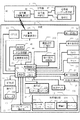
図13は、本発明の実施の形態に係るドライブレコーダシステムの第3実施例を示すブロック図である。第3実施例は基本的には図1の第1実施例と同様の構成なので、共通する部分には同一の番号を付し、特に必要のない限り説明は省略する。また、図13では、図1におけるよりも詳細に構成が図示されている部分があるが、これらは第1実施例においても備えられているものであり、特に断らない限り、第3実施例のみに備えられている特有の構成ではない。図13では、簡単のため図1の給油/給電スタンド6の図示を省略しているが、第3実施例も同様の構成を持っている。 FIG. 13 is a block diagram showing a third example of the drive recorder system according to the embodiment of the present invention. Since the third embodiment is basically the same as the first embodiment shown in FIG. 1, the same reference numerals are given to the common parts, and the description is omitted unless particularly required. Further, in FIG. 13, there is a portion whose configuration is shown in more detail than in FIG. 1, but these are also provided in the first embodiment, and unless otherwise specified, only the third embodiment. It is not a specific configuration provided in In FIG. 13, for the sake of simplicity, the illustration of the oil supply / power supply stand 6 of FIG. 1 is omitted, but the third embodiment also has the same configuration.
図13では、車両制御部8の不揮発性バッファメモリ202が図示されているとともに、操作部10のブレーキ204が図示されているが、これらは既に第1、第2実施例において言及してきた構成である。また、表示部16には表示パネル206およびスピーカ208が図示されているが、表示部16の機能に関連してアナウンスによる報知を行ってもよいことは既に説明したとおりであり、スピーカ208はこのようなアナウンスによる報知機能を担うものである。なお、図13では画像処理圧縮部210が図示されているが、これは、図1では車両制御部8が負担していた機能を分担する専用機能部である。従って、第3実施例では、今まで説明してきたフローにおける画像処理および圧縮機能は、車両制御部8と連携して画像処理圧縮部210により実行される。
In FIG. 13, the
図13では、さらに、車両機能部12における車両2のランプ関連の構成の詳細が図示されており、ブレーキランプ212および、ウインカ214は既にのべたブレーキ操作またはウインカ操作を行ったときに点灯または点滅するものである。車両機能部12にはさらにヘッドライト216および車幅灯218が図示されている。図13の第3実施例はさらに照度センサ220を備えており、これによって外部の明るさが測定され、夕闇がせまったことや車両がトンネルに入ったことなどが検知される。第3実施例は、このような照度センサ220とドライブレコーダシステムとの連携により、ヘッドライト216や車幅灯218の自動制御を行う機能を備えているものであるが、以下、これについて説明する。
FIG. 13 further shows details of the lamp-related configuration of the
図14は、図13の第3実施例における車両制御部8の機能を示す基本フローチャートである。その内容は、基本的には図9のフローチャートと共通であり、同一のステップには同一ステップ番号を付して説明を省略する。図14のフローが図9のフローと異なる部分は上記のヘッドライト216や車幅灯218の自動制御を行う機能が付加されていることであり、太字で示したステップがそれに該当する。また、ステップS282の電子透かし関連処理/圧縮記録処理は、図9のステップS210からステップS216をまとめて図示したものであり、その内容は図9と共通である。
FIG. 14 is a basic flowchart showing functions of the
ステップS282で圧縮記録処理が終了するとステップS284の通常運行関連処理に進む。ここでは、操作部10の操作や車両2への負荷や加速度変化に応じた通常運行に関する処理が行われる。そしてこれらの処理が終了するとステップS286のランプ制御処理に入る。その詳細は後述する。次いでステップS218に進むが、以下の処理は図9と同様である。なお、車両が走行可能状態である限り、ステップS26からステップS4に戻ってフローが繰り返され、その都度ステップS282からステップS286を経由するので、これらのステップでは最新の状況変化に応じた処理が実効される。ランプ制御処理も同様であって、フローの繰返しに伴ってステップS286に至る毎に、その時点の照度センサ220とドライブレコーダシステムの状況変化に即応し、ヘッドライト214や車幅灯216の点灯や消灯についての自動制御が行われる。
When the compression recording process ends in step S282, the process proceeds to the normal operation related process in step S284. Here, the process regarding the normal operation according to operation of the
図15は、図14のステップS286におけるランプ制御処理の詳細を示すフローチャートである。フローがスタートすると、ステップS292において、車両2のランプ関連の制御について操作部10によって自動制御設定がされているかどうかチェックする。そして自動制御設定であればステップS294に進み、照度センサ220によって検知される車外の明るさが中照度限界以下かどうかチェックする。中照度限界とは夕刻において、車幅灯218を点灯させたほうが安全上適切であると判断される限界の照度である。ステップSで中照度限界以下であることが検出されるとステップS296に進み車幅灯218を自動点灯させてステップS298に進む。
FIG. 15 is a flowchart showing details of the lamp control process in step S286 of FIG. When the flow starts, in step S292, it is checked whether or not automatic control is set by the
ステップS298では、照度センサ220によって検知される車外の明るさが低照度限界以下かどうかチェックする。低照度限界とは夜間またはトンネル進入等の状態であって、車幅灯218に加えヘッドライト216も点灯させるべきであると判断される限界の照度である。これに該当すると判断された場合はステップS300に進む。
In step S298, it is checked whether the brightness outside the vehicle detected by the
ステップS300では、車両2が停車中か否かをチェックし、停車中でなければ走行中であることを意味するのでステップS302に進み、直ちにヘッドライト点灯を指示してフローを終了する。上記のように図15のランプ制御処理が終了すると図14のステップS218以下に進み、車両が走行可能状態である限りフローが繰り返されて、その都度ステップS286に至り、図15のフローが再スタートする。従って、短時間の間に図15のフローが繰返し機能し、照度センサ220とドライブレコーダシステムの状況変化に即応し、例えばヘッドライト214を消灯すべき状態にないかどうかや消灯後に再点灯させるべき状態にないかどうかをチェックして自動制御する。次にステップS300以下の機能に基づいてこのような制御を説明する。
In step S300, it is checked whether or not the
ステップS300で停車中であることが検出されるとステップS304に進み、ドライブレコーダ機能において車両近距離通信部24が信号灯情報を取得しているかどうかチェックする。そして取得があればステップS306に進み、その情報を流用するとともにステップS308でドライブレコーダ機能における方位検知部44の情報を流用してステップS310に移行する。ステップS310では、これらの情報の流用により車両進行方向の信号灯の色がわかるのでそれが赤かどうかチェックする。
If it is detected in step S300 that the vehicle is stopped, the process proceeds to step S304, and it is checked whether the vehicle short-
ステップS310で進行方向の信号灯が赤であることが検知されるとステップS312に進み、ブレーキ204が操作中であるかどうかチェックする。そして操作中であればステップS314に進んでブレーキ操作により車両が停止してから所定時間(例えば2秒)が経過したかどうかチェックする。これに該当すればステップS316に進み、ヘッドライト消灯を指示してフローを終了する。すなわち、進行方向の信号が赤でブレーキを踏んで停車し、2秒程度経過して運転者が交差点でのエチケットとしてヘッドライトを消灯したいと感じたころに自動的にヘッドライトの消灯が指示される。なお、この場合、停車後初めてステップS316に至ったのであれば、以前にステップS302によりヘッドライトが点灯状態にあるので、消灯指示が実行される。これに対し、既にステップS316によってヘッドライト消灯が指示され、その状態が継続していてフローの繰返しにより再びステップS316に至ったのであれば、ヘッドライトの消灯が継続されることになる。
If it is detected in step S310 that the signal lamp in the traveling direction is red, the process proceeds to step S312 to check whether the
一方、ステップS304で信号灯情報が取得されていないときは、停車中であってもステップS302に進んでヘッドライト点灯が指示される。この場合も、以前にステップS302によりヘッドライトが点灯状態にあればヘッドライトの点灯が継続されることになる。これは、例えば信号灯のないところで車両2が停車したとき少なくともエチケット上はヘッドライトを消灯する必要がないので、運転者の意向に任せて自動消灯は控えることを意味する。一方、以前にステップS316によりヘッドライトが消灯状態にあってステップS304経由でステップS302に至った時はヘッドライトの点灯が実行されるが、これは、何らかの事情により信号灯の情報が得られなくなったときには運行上の安全のためヘッドライトの自動消灯を中止するのが適当だからである。
On the other hand, when the signal light information is not acquired in step S304, the process proceeds to step S302 even when the vehicle is stopped, and the headlight lighting is instructed. In this case as well, if the headlight has been previously turned on in step S302, the headlight is continuously turned on. This means that, for example, when the
また、ステップS310で信号灯情報が赤でないときは、停車中であってもステップS302に進んでヘッドライト点灯が指示される。この場合も、以前にステップS302によりヘッドライトが点灯状態にあればヘッドライトの点灯が継続される。これは、車両が停止したとしても信号灯が赤でない場合はヘッドライトを自動消灯するのが不適当だからである。一方、以前にステップS316によりヘッドライトが消灯状態にあってステップS310経由でステップS302に至った時はヘッドライトの点灯が実行されるが、これは、信号が赤から青に変わった場合に該当し、その場合は、運転者のブレーキ操作の如何にかかわらず運行上の安全のためヘッドライトを点灯させることが適当だからである。運転者が信号の変化に気づくのが遅れ、ブレーキ操作を解除しなかった場合でも、信号灯の変化により対向車が発信している可能性があり、ヘッドライトの消灯が継続することは危険だからである。 If the signal light information is not red in step S310, the process proceeds to step S302 even when the vehicle is stopped, and the headlight lighting is instructed. Also in this case, if the headlight has been turned on previously in step S302, the lighting of the headlight is continued. This is because it is inappropriate to automatically turn off the headlight if the signal light is not red even if the vehicle stops. On the other hand, when the headlight was previously turned off in step S316 and reached step S302 via step S310, the headlight is turned on, which corresponds to the case where the signal changes from red to blue. In this case, it is appropriate to turn on the headlight for safety in operation regardless of the driver's brake operation. Even if the driver is late in noticing the change in the signal and does not release the brake operation, the oncoming vehicle may be transmitting due to the change in the signal light, and it is dangerous to keep the headlights off. is there.
さらに、ステップS312でブレーキ操作中でなければ、進行方向信号灯が赤であってもステップS302に進んでヘッドライト点灯が指示される。この場合も、以前にステップS302によりヘッドライトが点灯状態にあればヘッドライトの点灯が継続される。これは、信号灯が赤であってもブレーキ操作が行われていなければヘッドライトを自動消灯するのは危険と考えられるからである。一方、以前にステップS316によりヘッドライトが消灯状態にあってステップS312経由でステップS302に至った時はヘッドライトの点灯が実行されるが、これも、進行方向信号が赤であるにもかかわらずブレーキ操作が中止されたときは車両が発信する可能性があり、ヘッドライトを速やかに点灯させることが適当だからである。 Further, if the brake is not being operated in step S312, the process proceeds to step S302 and the headlight lighting is instructed even if the traveling direction signal lamp is red. Also in this case, if the headlight has been turned on previously in step S302, the lighting of the headlight is continued. This is because even if the signal light is red, it is considered dangerous to automatically turn off the headlight if the brake operation is not performed. On the other hand, when the headlight was previously turned off in step S316 and the process reached step S302 via step S312, the headlight is turned on, even though the traveling direction signal is red. This is because when the brake operation is stopped, the vehicle may make a transmission, and it is appropriate to turn on the headlight promptly.
ブレーキ操作中であっても、ステップS314でブレーキ操作により車両が停止してから所定時間(例えば2秒)が経過していなければステップS302に進んでヘッドライト点灯が指示される。この場合も、以前にステップS302によりヘッドライトが点灯状態にあればヘッドライトの点灯が継続される。これは、ブレーキ操作があっても、その後間を置かずに信号灯が赤から青に変わる可能性があり、ブレーキ操作直後に間髪を入れずヘッドライトの消灯を指示するのは適当でないからである。上記ステップS312においてブレーキ操作中止直後にステップS302に進んでヘッドライト点灯を指示する場合とは対照的である。なお、以前にステップS316によりヘッドライトが消灯状態にあってステップS314経由でステップS302に至る場合というのは存在しない。 Even during the brake operation, if a predetermined time (for example, 2 seconds) has not elapsed since the vehicle was stopped by the brake operation in step S314, the process proceeds to step S302 and the headlight lighting is instructed. Also in this case, if the headlight has been turned on previously in step S302, the lighting of the headlight is continued. This is because even if there is a brake operation, the signal light may change from red to blue without a pause, and it is not appropriate to instruct to turn off the headlight without putting a short hair immediately after the brake operation. . This is in contrast to the case where the process proceeds to step S302 immediately after stopping the brake operation in step S312 and the headlight lighting is instructed. Note that there is no case where the headlight was previously turned off in step S316 and the process reaches step S302 via step S314.
ステップS292において、車両2のランプ関連の制御について操作部10による自動制御設定が検出されなかった時はステップS318に移行し、手動制御処理が行われる。これは手動でランプ関連の点灯または消灯操作があったときこれに応じる処理である。そしてステップS320において、ヘッドライト216の自動消灯モードが設定されているかどうかがチェックされる。自動消灯モードとは手動でヘッドライトを点灯させた場合でも交差点等におけるエチケットのための自動消灯を行うモードである。そしてこのモードが設定されていなければ直ちにフローを終了する。一方、ステップS320において自動消灯モードが設定されていることが検出されたときはステップS322に進み、操作部10がヘッドライト点灯位置にセットされているかどうかチェックする。そして点灯位置にセットされていなければ、直ちにフローを終了する。
In step S292, when the automatic control setting by the
これに対し、ステップS322で操作部10がヘッドライト点灯位置にセットされていることが検出された場合はステップS300に移行し、以下、自動制御設定がされている場合と同様の信号灯設置場所における停車時のヘッドライト自動消灯制御が行われる。そして、自動消灯された場合は、再度ステップ292からステップS322を経由してステップS300に戻り、ステップS300以下の条件に従って自動的に点灯状態に復帰する。このように第3実施例では、明るさに応じたヘッドライトの自動制御を行わない場合でも、交差点等におけるエチケットのための自動消灯を行うことができる。
On the other hand, when it is detected in step S322 that the
なお、ステップS294において車外の照度が中照度限界以下であることが検出されなかったときは日中の戸外での運行と考えられるので、ステップS324に進んで車幅灯218の消灯を指示し、次いでステップS326でヘッドライト216の消灯を指示してフローを終了する。また、ステップS298において車外の照度が低照度限界以下であることが検出されなかったときはステップS326に移行してヘッドライト216の消灯を指示し、フローを終了する。この場合、ステップS296において指示された車幅灯218の点灯は維持される。なお、以上の場合において、車幅灯218またはヘッドライト216が点灯していた場合は指示に応じて消灯が実行されるが、これらがすでに消灯しているときは、消灯指示に応答してそれら消灯状態が継続される。
In addition, when it is not detected in step S294 that the illuminance outside the vehicle is below the middle illuminance limit, it is considered that the vehicle is operating outdoors during the day, so the process proceeds to step S324 to instruct to turn off the
図16は、図14のステップS286におけるランプ制御処理の他の例の詳細を示すフローチャートである。図16のフローは太字で示したステップを除き、基本的には図15のフローと共通である。従って同一のステップには同一ステップ番号を付して説明を省略する。図16のフローでは、ステップS300に至って停車中であることが検出されたとき、ヘッドライトを点灯または消灯させる指示を出す処理が図15と異なっているので、この点について説明する。 FIG. 16 is a flowchart showing details of another example of the lamp control process in step S286 of FIG. The flow in FIG. 16 is basically the same as the flow in FIG. 15 except for the steps shown in bold. Therefore, the same step number is assigned to the same step, and the description is omitted. In the flow of FIG. 16, the processing for issuing an instruction to turn on or off the headlight when it is detected that the vehicle is stopped at step S300 is different from that in FIG. 15, and this point will be described.
ステップS300で停車中であることが検出されるとステップS322に進み、ブレーキ204が操作中であるかどうかチェックする。そして操作中であればステップS334に進んでブレーキ操作により車両が停止してから所定時間(例えば2秒)が経過したかどうかチェックする。これに該当すればステップS336に移行して停車中のGPS情報の分析が行われ、次いでステップS94で停車位置にGPSの信号灯位置が抽出されるかどうかチェックする。そして検出があれば信号待ちのために所定時間以上停車していると看做してステップS316に移行し、ヘッドライト消灯を指示する。
If it is detected in step S300 that the vehicle is stopped, the process proceeds to step S322 to check whether the
一方、ステップS338でGPSによる信号灯位置の抽出ができなかった場合は、ステップS340に進み、不揮発バッファメモリ202にFIFO記録されている停車直線の画像情報を分析し、ステップS342で停車直前の車両位置の進行方向に信号灯の画像が抽出されるかどうかチェックする。そして信号灯画像が抽出されると、運転者がその信号を見て停車し、信号の変わるのを待って所定時間以上停車を続けていると看做してステップS316に移行し、ヘッドライト消灯を指示する。
On the other hand, if the signal light position cannot be extracted by GPS in step S338, the process proceeds to step S340, where the image information of the stopping straight line recorded in the FIFO in the
なお、ステップS332でブレーキ操作中でない場合、または、ブレーキ操作停止後所定時間経過していない場合はステップS302に移行してヘッドライト点灯指示を行う。また、ステップS342で信号灯画像が抽出できなかったときは、停車が信号待ちであることが確認できないのでステップS302に移行し、ヘッドライト点灯指示を行う。 If the brake operation is not being performed in step S332, or if the predetermined time has not elapsed since the brake operation was stopped, the process proceeds to step S302 and a headlight lighting instruction is issued. If the signal light image cannot be extracted in step S342, it cannot be confirmed that the stop is waiting for the signal, so the process proceeds to step S302, and a headlight lighting instruction is issued.
図16のフローも、図14のフローがステップS26からステップS4に戻ることによって繰り返されるが、ステップS316の指示によるヘッドライト消灯状態で再度ステップS332に至り、ブレーキ操作が解除されたことが検出されればステップS302に移行し、ヘッドライトが再点灯する。また、以前ステップS334に至った時は所定時間が経過しておらず、その結果ステップS302の指示によるヘッドライト点灯状態となり、その後再度ステップS334に至ってブレーキ操作停止後所定時間経過が検出されたときはステップS336移行に進み、信号灯の検出があればステップS316の指示によるヘッドライト消灯となることもある。 The flow of FIG. 16 is also repeated by returning the flow of FIG. 14 from step S26 to step S4. However, it is detected that the brake operation has been released by reaching step S332 again in the headlight extinguishing state according to the instruction of step S316. Then, the process proceeds to step S302, and the headlight is turned on again. Further, when step S334 has been reached before, the predetermined time has not elapsed, and as a result, the headlight is turned on according to the instruction in step S302, and then after step S334 again, the predetermined time has elapsed after stopping the brake operation. The process proceeds to step S336, and if a signal lamp is detected, the headlight may be turned off according to the instruction in step S316.
上記のような図15または図16のランプ制御処理の詳細は車両2の設計思想によりいずれか一方のみを採用することも可能であるが、両者を一台の車両2に備えておき、運転者の判断でいずれか一方を予め選択しておけるように構成してもよい。なお、図15または図16におけるステップS316ではヘッドライトを消灯させる指示が行われているが、本発明の実施はヘッドライトの消灯に限るものではなく、ヘッドライトの減光、または前方の照射を和らげるための照射方向の変更であってもよい。このようなエチケットのためのヘッドライトの消灯、減光および照射方向の変更等について、本発明では「点灯中のヘッドライトの状態変化」と総称するものとする。なお、この場合、図15または図16のステップS302において行われるヘッドライトの「点灯」とは通常走行中のヘッドライトの点灯を意味するものとする。
As for the details of the lamp control process of FIG. 15 or FIG. 16 as described above, it is possible to adopt only one of them depending on the design concept of the
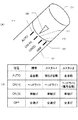
図17は、図13の第3実施例における操作部10の要部斜視図および機能説明図である。図17(A)は、操作部10における車両2のランプ関連の制御に関する設定操作部を示し、ウインカ操作レバー302はこれを上下させることにより、左または右のウインカを点滅させる。ウインカ操作レバー302の先端には、ランプ制御設定ダイヤル304が設けられており、これを回転させて指標306をOFF位置308、ON(S)位置310、ON(H)位置312およびAUTO位置314のいずれかに合わせることによりランプ制御設定が可能となっている。図17(B)は各位置の機能を示す機能説明図であり、各機能の標準設定の内容とともに機能のカスタム設定が可能なことを示している。カスタム設定は、別に設けられた操作部10の設定ボタンと表示パネル206によるGUIにより変更および選択可能である。
FIG. 17 is a perspective view and a function explanatory diagram of the main part of the
まず、標準設定について説明すると、図17(A)の指標306を、OFF位置308に合わせた場合、ヘッドライト216および車幅灯218が全てオフとなる。また、ON(S)位置310およびON(H)位置312は手動制御位置であり、指標306をON(S)位置310に合わせた場合は、車幅灯218のみがオンとなる。一方、指標306をON(H)位置312に合わせた場合はヘッドライト216および車幅灯218の両者がオンとなる。AUTO位置314は全自動制御位置であり、指標306をAUTO位置314に合わせた時は、図15または図16に示したような車外の明るさに応じたヘッドライト216の自動点灯および自動消灯、ならびに信号灯設置場所における停車/発進時のヘッドライト216の自動消灯および自動再点灯の制御が行われる。この配置により、手動によるON(S)位置310とON(H)位置312の手動切換えはランプ制御設定ダイヤル304の一ステップの回転で可能になるとともに、AUTO位置314への設定のままで信号灯設置場所におけるヘッドライト216の消灯および再点灯の制御が可能となる。
First, the standard setting will be described. When the
図17(B)のカスタムAは、AUTO位置314において、車外の明るさに応じたヘッドライト216の自動点灯および自動消灯のみが行われる在来の機能設定であり、運転者が望む場合にはこのような設定も可能となっている。ここで、注意すべきは、AUTO位置314がON(H)位置312を挟んでON(S)位置310の反対側に設けられていることである。従って、指標306をAUTO位置314に合わせている状態において信号灯設置場所に至り、手動でヘッドライトを消灯しようとすれば、AUTO位置314からがON(H)位置312を経由してON(S)位置310までランプ制御設定ダイヤル304を二ステップ回転させる必要があり、誤ってOFF位置308まで回しきってしまう恐れもある。また、手動再点灯の際AUTO位置314に戻すにはON(S)位置310からランプ制御設定ダイヤル304を再度二ステップ回転させる必要がある。このため信号灯設置場所で停止したときに手動でこまめにヘッドライトを消灯する習慣のある運転者にとっては、AUTO位置314が利用しにくい設定となる。これに対し、標準設定では、上記のようにAUTO位置314に設定したままで、車外の明るさおよび信号灯に応じたヘッドライト216の自動消灯および自動再点灯の制御が可能となる。
The custom A in FIG. 17B is a conventional function setting in which the
図17(B)のカスタムBは、ON(H)位置312以外の機能は標準設定と同様である。カスタムBにおけるON(H)位置312では、車外の明るさに応じたヘッドライト216の自動制御はせず、基本的に手動のヘッドライトオン機能とする。しかしながら、これに加え、信号灯設置場所における停車/発進時のヘッドライト216の自動消灯および自動再点灯についてはAUTO位置と同様の自動機能とする。従って、何らかの理由により手動でヘッドライト216の消灯および点灯操作をしようとすれば、ON(H)位置312とON(S)位置310の間でランプ制御設定ダイヤル304を一ステップ回転だけ回転させればよく、さらに、信号灯設置場所でのヘッドライト216の消灯および再点灯についてはAUTO位置314に指標306を合わせた場合と同様、操作の必要がないものとなる。これは、図15、または図16のステップS320からステップS322を経由してステップS300に至る機能に該当する。このように、カスタムBでは、点灯が自動的に行われたか手動でおこなわれたかに係らず、信号灯の存在の検出に基づいて通常点灯中のヘッドライトの状態を自動的に変化させる。
In the custom B of FIG. 17B, functions other than the ON (H)
図18は、本発明の実施の形態に係るドライブレコーダシステムの第4実施例を示すブロック図である。第4実施例では、特にドライブレコーダに記録される車両2の走行状況と燃費との関係を把握する構成について詳細に説明される。第4実施例は、ブロック構成としては、図1を援用する第2実施例、ならびに図13に示される第3実施例と同様であり、共通する部分には同一の番号を付すとおもに、特に必要のない限り説明は省略する。また、図18では、図13の第3実施例と同様にして、図1におけるよりも詳細に構成が図示されている部分があるが、これらは第1実施例や第2実施例のブロック構成においても備えられているものであり、特に断らない限り、第4実施例のブロックのみに備えられている特有の構成ではない。また、図14では、簡単のため図1の給油/給電スタンド6の図示を省略しているが、第3実施例と同様にして、第4実施例も同様の構成を持っている。
FIG. 18 is a block diagram showing a fourth example of the drive recorder system according to the embodiment of the present invention. In the fourth embodiment, a configuration for grasping the relationship between the traveling state of the
図18の第4実施例では、その機能の説明に必要ないくつかのブロックが図18中に追加されている。まず、操作部10はブレーキ204だけでなく、ハンドル402およびアクセル404が図示されている。さらに、車両の走行情報を検知する検知部として傾斜検知部406が追加されている。この傾斜検知部406は車両2が平地走行中であるか、または登坂中であるか、または下坂中であるかを検知するものであり、その検知結果は燃費に関係する走行情報となる。
In the fourth embodiment shown in FIG. 18, several blocks necessary for explaining the function are added in FIG. First, the
車両機能部12のランプ系408は、図13のブレーキランプ212、ウインカ214、ヘッドライト216および車幅灯218をまとめて図示したものであり、その構成は図13と同じである。図18の車両機能部12はさらに、エンジン410へのガソリン噴射状況および速度計46がモニタする走行メカ412の速度から瞬間燃費を算出する瞬間燃費計414を有する。
The
さらに図18では、信号灯4の制御および信号灯4を介して車両2と通信しているサーバ416が図示されている。サーバ416は、サーバ制御部420の制御に基づいてインターネット422を介し信号機システム通信部42と通信するサーバ通信部424を有する。サーバ制御部420は、信号機4の系統点灯を制御するとともに、既に説明したように信号機4を介して車両2に渋滞情報などを伝達する。さらに、サーバ制御部420は、図1の給油/給電スタンド6のスタンド制御部54(またはこれを読替えたETC6のETC制御部54)と同様にして、信号機4を介して電子透かし処理キー情報や「優良運転者証明」を車両2に伝達することができる。なお、信号機システム通信部42とサーバ通信部424との通信はインターネット422に限るものではなく、専用回線を介して行うことも可能である。
Further, in FIG. 18, a
図19は、図18の第4実施例における車両制御部8の機能を示す基本フローチャートである。その内容は、基本的には図14のフローチャートと共通であり、同一のステップには同一ステップ番号を付して説明を省略する。図19のフローが図9のフローと異なる部分は、ドライブレコーダに記録される車両2の走行状況と燃費との関係を示すドライブ解析およびその結果のドライバーへの告知に関する部分であり、太字で示したステップがそれに該当する。
FIG. 19 is a basic flowchart showing functions of the
図2、図9、図14と同様にして、イグニションのオンまたは走行準備スイッチのオンによってフローがスタートすると、まずステップS352でドライブレコーダ機能を含む車両機能を初期チェックする。この処理は、図2、図9、図14のステップS2と同様のものであり、チェック結果の表示またはアナウンスによる通知を含む。ステップS352では、さらに車両2の走行状況と燃費との関係を示すドライブ解析の結果の告知処理が行われる。これは、車両2の運転の始業時点においてそれまでに解析が完了して記憶されているドライブ解析結果があればこれを告知するものであるが、その詳細については後述する。ステップS352の処理が終了するとステップS4に進むことは、図2、図9、図14と同様である。
As in FIG. 2, FIG. 9, and FIG. 14, when the flow is started by turning on the ignition or turning on the travel preparation switch, first, vehicle functions including the drive recorder function are initially checked in step S352. This process is the same as step S2 in FIG. 2, FIG. 9, and FIG. 14, and includes notification of a check result display or announcement. In step S352, a notification process of the result of the drive analysis indicating the relationship between the traveling state of the
ステップS4においてカメラ26およびマイク28からの情報に基づく画像と音の記録が行われてステップS354に進む。ステップS354は図2、図9、図14のステップS6と同様にしてその時点におけるGPS部20からのGPS情報、方位検知部44からの進行方向情報、時計18からの時刻情報および操作部10よりの操作情報をそれぞれ取得するものであるが、走行情報としては、速度計46からの速度情報の他、加速度検知部30からの加速度(カーブ走行時や方向転換時の角加速度も含む)および傾斜検知部406からの車両2の傾斜情報も取得する。さらにステップS354では瞬間燃費計414からの燃費情報も取得する。
In step S4, an image and sound are recorded based on information from the
次いで、ステップS356では、ステップS354で取得された各種の情報に基づく車両2の走行状況と燃費との関係を解析するためのドライブ解析処理を行ってステップS8に移行する。ステップS356の詳細は後述する。図19では、図14と同様のステップS10とステップS210の間にステップS358およびステップS360が挿入されている。ステップS358は、ステップS354で得られた各種の情報にステップS10で得られた信号灯情報を加味して車両2の走行状況と燃費との関係を解析するためのドライブ解析処理を行う。その詳細はステップS356と一括して後述する。また、ステップS360は、車両外からの情報受信およびステップS354およびステップS10で得られた各種の情報(必要に応じてステップS358における解析結果)の車両外への送信を行うための情報交信処理である。ここにステップS358およびステップS360が置かれている理由は、これらの機能をステップS8における信号灯情報着信によってトリガーし、信号灯4を介してサーバ416と通信するためである。
Next, in step S356, drive analysis processing is performed to analyze the relationship between the traveling state of the
図19では、図14と同様にして、ステップS284の通常運行関係処理が終わるとステップS362のランプ制御処理に入る。図19のステップS362では、さらにここで解析告知処理を行う。これは、ランプ制御処理において停車時にヘッドライトを消灯する際、ドライブ解析結果があればこれを告知するためであるが、その詳細についてはステップS352の解析告知処理の詳細とも関連させて後述する。運転開始後のドライブ解析結果の告知は車両走行中にこれを行うと煩わしいばかりか危険ですらあるので、このように信号待ち中など運転に支障のないタイミングを図って実行する。 In FIG. 19, similarly to FIG. 14, when the normal operation related process in step S <b> 284 ends, the lamp control process in step S <b> 362 is entered. In step S362 of FIG. 19, an analysis notification process is further performed here. This is to notify if there is a drive analysis result when the headlight is turned off when the vehicle is stopped in the lamp control process, and details thereof will be described later in connection with the details of the analysis notification process in step S352. Since the notification of the drive analysis result after the start of driving is bothersome and dangerous if it is performed while the vehicle is running, it is executed at a timing that does not hinder driving such as waiting for a signal.
図19におけるステップS220は、図14と同様の情報交換処理であるが、図14で述べた情報交換の他、ステップS354およびステップS10で得られた各種の情報(および必要に応じてステップS356またはステップS358における解析結果)のサーバ416への送信を行う。図19においてここにステップS220が存在する意義は、ステップS354およびステップS10で得られた各種の情報(および必要に応じてドライブ解析結果)の送信をステップS218における通信可能状態検知によってトリガーし、信号灯4以外の手段によってもサーバ416との通信を行えることである。
Step S220 in FIG. 19 is an information exchange process similar to that in FIG. 14, but in addition to the information exchange described in FIG. 14, various information obtained in steps S354 and S10 (and step S356 or as necessary). The analysis result in step S358 is transmitted to the
図19に図示されているステップS364は、図14におけるステップS26からステップS30の各ステップでチェックしている内容を簡単のため「停止条件」としてまとめたものであり、チェックしている内容は図14と全く同じである。図14と同様にして走行可能状態でなく(ステップS26のチェックに該当)、かつ動体検知もなく(ステップS28のチェックに該当)、かつ所定時間無検知が継続すると停止条件に該当することとなり、ステップS366に移行する。ステップS366は、図14のステップS32と同様、動画/音記録および諸情報取得を停止するものであるが、ステップS366ではさらにドライブ解析結果があればこれを告知するものである。これは、車両を停止して運転を終了する際においてドライバーへの告知を行うためのものであるが、その詳細は、ステップS352の詳細説明に関連して後述する。ステップS366の処理が終わると図19のフローは終了する。 Step S364 shown in FIG. 19 summarizes the contents checked in steps S26 to S30 in FIG. 14 as “stop conditions” for the sake of simplicity. 14 is exactly the same. As in FIG. 14, the vehicle is not in a travelable state (corresponding to the check in step S26), no moving object is detected (corresponding to the check in step S28), and if no detection continues for a predetermined time, the stop condition is satisfied. The process proceeds to step S366. Step S366 stops moving image / sound recording and acquisition of various information as in step S32 of FIG. 14. In step S366, if there is a drive analysis result, this is notified. This is for notifying the driver when the vehicle is stopped and the driving is ended, and details thereof will be described later in connection with the detailed description of step S352. When the process of step S366 ends, the flow of FIG. 19 ends.
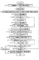
図20は、図19のステップS356およびステップS358におけるドライブ解析処理の詳細を示すフローチャートである。フローがスタートするとステップS372で前回の評価確定後、評価単位となる走行距離(例えば5キロ)に達しているかどうかをチェックする。そして評価単位走行距離に達していればステップS374に進み、現在の評価ファイルを確定する。評価ファイルとは、図19のステップS354およびステップS10で得られる諸情報および図20のステップS378で更新されるデータを評価単位走行距離分蓄積したものである。さらに、ステップS376で次の単位評価走行距離用の新評価ファイルを作成してステップS378に移行する。一方、ステップS372で評価単位走行距離に到達していなければ直接ステップS378に移行する。このようにして、ステップS372で評価単位走行距離到達が検出されるとステップS378以下のデータの更新は新評価ファイルに対して行われるとともに、ステップS372で評価単位走行距離到達が検出されない場合は、ステップS378以下のデータの更新は現評価ファイルに対して行われることになる。 FIG. 20 is a flowchart showing details of the drive analysis processing in steps S356 and S358 of FIG. When the flow starts, it is checked in step S372 whether or not the travel distance (for example, 5 km) that is an evaluation unit has been reached after the previous evaluation is confirmed. If the evaluation unit travel distance has been reached, the process proceeds to step S374 to determine the current evaluation file. The evaluation file is obtained by accumulating various pieces of information obtained in steps S354 and S10 in FIG. 19 and data updated in step S378 in FIG. 20 for the evaluation unit travel distance. Further, in step S376, a new evaluation file for the next unit evaluation travel distance is created, and the process proceeds to step S378. On the other hand, if the evaluation unit travel distance has not been reached in step S372, the process directly proceeds to step S378. In this manner, when the evaluation unit travel distance arrival is detected in step S372, the data update in step S378 and subsequent steps is performed on the new evaluation file, and when the evaluation unit travel distance arrival is not detected in step S372, The update of data after step S378 is performed on the current evaluation file.
ステップS378では、評価ファイルに蓄積されている燃費計情報にステップS354で新たに得られた燃費計情報を加味して平均燃費を計算し直し、評価ファイルの平均燃費データを更新する。ついでステップS380では、平地を定速走行中以外の状態における燃費データを評価ファイルから抽出する。これは、平地定速度走行状態の燃費は比較的ドライブテクニックに影響されないのでそれ以外の走行状態における燃費データを抽出して分析するためである。そして、次のステップS382において、まず抽出した燃費データ中に新規に取得された発進時の燃費データがあるかどうかチェックする。 In step S378, the average fuel consumption is recalculated by adding the fuel consumption meter information newly obtained in step S354 to the fuel consumption meter information accumulated in the evaluation file, and the average fuel consumption data in the evaluation file is updated. In step S380, fuel consumption data in a state other than traveling at a constant speed on a flat ground is extracted from the evaluation file. This is because the fuel consumption in the flat-level constant-speed driving state is relatively unaffected by the drive technique, so that the fuel consumption data in other driving states is extracted and analyzed. Then, in the next step S382, first, it is checked whether or not the fuel consumption data at the start is newly acquired in the extracted fuel consumption data.
ステップS382で新規発進燃費データが検出されないときはステップS384に進み、ステップS380で抽出した燃費データ中に新規に取得された平地加速時の燃費データがあるかどうかチェックする。ステップS384で新規平地加速燃費データが検出されないときはステップS386に進み、ステップS380で抽出した燃費データ中に新規に取得された登坂中の燃費データがあるかどうかチェックする。登坂中かどうかは図18の傾斜検知部406からの情報により判断される。ステップS386で新規登坂燃費データが検出されないときはステップS388に進み、ステップS380で抽出した燃費データ中に新規に取得された平地減速時の燃費データがあるかどうかチェックする。ステップS388で新規平地原則燃費データが検出されないときはステップS390に進み、ステップS380で抽出した燃費データ中に新規に取得された下坂中の燃費データがあるかどうかチェックする。下坂中かどうかについても、図18の傾斜検知部406からの情報により判断される。
If new starting fuel consumption data is not detected in step S382, the process proceeds to step S384, and it is checked whether or not there is newly acquired fuel acceleration data during flat ground acceleration in the fuel consumption data extracted in step S380. When the new flat acceleration fuel consumption data is not detected in step S384, the process proceeds to step S386, and it is checked whether or not the newly acquired fuel consumption data on the uphill is included in the fuel consumption data extracted in step S380. Whether or not the vehicle is climbing is determined based on information from the
ステップS390で新規下坂中の燃費データが新規取得燃費データ中にあることが検出された場合はステップS392に進み、エンジンブレーキ状態発生データを下坂中の燃費データと関連付けて更新する。次いでステップS392では、ブレーキ操作データを下坂中の燃費データと関連付けて更新し、ステップS396に移行する。なお、ステップS392およびステップS394は該当するデータが発生するものと看做して設けられているが、該当するデータがなければ結果的に直接ステップS396に移行することになる。 If it is detected in step S390 that the fuel consumption data during the new downhill is in the newly acquired fuel consumption data, the process proceeds to step S392, and the engine brake state occurrence data is updated in association with the fuel consumption data during the downhill. Next, in step S392, the brake operation data is updated in association with the fuel economy data during the downhill, and the process proceeds to step S396. Note that steps S392 and S394 are provided assuming that the corresponding data is generated, but if there is no corresponding data, the process directly proceeds to step S396.
一方、ステップS382で発進時の新規燃費データがあることが検出されたとき、またはステップS384で平地加速中の新規燃費データあることが検出された時、またはステップS386で登坂中の新規燃費データがあることが検出された時はいずれもステップS398に移行し、アクセル操作データをそれぞれ対応する燃費データと関連付けて更新してステップS396に移行する。また、ステップS388で平地減速中の新規燃費データがあることが検出されたときは、ステップS394に進み、ブレーキ操作データを平地減速中の燃費データと関連付けて更新してステップS396に移行する。さらに、ステップS390で下坂中の燃費データが新規取得燃費データ中にあることが検出されない場合は直接ステップS396に移行する。 On the other hand, when it is detected in step S382 that there is new fuel consumption data at the time of starting, or when it is detected in step S384 that there is new fuel consumption data during acceleration on flat ground, or in step S386, new fuel consumption data during climbing is updated. When it is detected that there is, the process proceeds to step S398, the accelerator operation data is updated in association with the corresponding fuel consumption data, and the process proceeds to step S396. If it is detected in step S388 that there is new fuel consumption data during deceleration on the flat ground, the process proceeds to step S394, the brake operation data is updated in association with the fuel consumption data during deceleration on the flat ground, and the process proceeds to step S396. Furthermore, if it is not detected in step S390 that the fuel economy data for the downhill is in the newly acquired fuel consumption data, the process directly proceeds to step S396.
ステップS396では、ステップS380で抽出した燃費データ中に新規に取得されたカーブ走行は方向転換による角加速度発生中の燃費データがあるかどうかチェックする。各加速度の発生は加速度検知部30により検知される。ステップS396で角加速度発生中の新規燃費データがあることが検出されたときは、ステップS400に進み、ハンドル操作データを角加速度発生中の燃費データと関連付けて更新してステップS402に移行する。一方、ステップS396で角加速度発生中の燃費データが新規取得燃費データ中にあることが検出されない場合は直接ステップS402に移行する。ステップS402では、以上の操作や状況において実際に発生した加速度データをその状況における燃費データと関連付けて更新し、ステップS404に移行する。ステップS404は以上の処理に基づいてドライブ解析データを作成する処理であるがその詳細は後述する。ステップS404のドライブ解析データ作成処理の後、フローは終了する。
In step S396, it is checked whether or not the newly acquired curve traveling in the fuel consumption data extracted in step S380 has fuel consumption data in which angular acceleration is being generated due to a turn. Generation of each acceleration is detected by the
図21は、図20のステップS404におけるドライブ解析データ作成処理の詳細を示すフローチャートである。フローがスタートするとステップS412で更新平均燃費をドライブ解析データとして上書記憶する。この更新平均燃費は図20のステップS378で得られたものである。次いでステップS414において更新した平均燃費が同車種平均よりも低いかどうかチェックする。この同車種平均燃費は、車両2を含む多数の同車種から集結される燃費データに基づいて図18のサーバ416が算出し車両2にフィードバックされたものである。車両2の平均燃費が同車種平均より低い場合はステップS416に進み、告知のための「燃費低下」を解析データとして上書記憶してステップS418に移行する。一方、車両2の平均燃費が同車種平均を上回る場合は直接ステップS418に移行する。
FIG. 21 is a flowchart showing details of the drive analysis data creation processing in step S404 of FIG. When the flow starts, the updated average fuel consumption is overwritten and stored as drive analysis data in step S412. This updated average fuel efficiency is obtained in step S378 of FIG. Next, in step S414, it is checked whether or not the updated average fuel consumption is lower than the same vehicle type average. The average vehicle type fuel efficiency is calculated by the
ステップS418では、図20のステップS374によって新規に確定された評価ファイルがあるかどうかチェックする。これは新規確定評価ファイルに累積された例えば5キロの所定走行距離分の諸情報に基づいて、ステップS418以下のドライブ解析を行う必要があるかどうかを見るためである。ドライブ解析の必要な新規確定評価ファイルがある場合はステップS420に進み、図20のステップS382からステップS390でチェックされるそれぞれの状況およびステップS396でチェックされる角加速度の有無の組合せによって分類される平地定速度走行以外の各状況についての累積燃費データが平均燃費に寄与する率をそれぞれ算出する。これは燃費の低下への寄与が大きい状況の抽出とその状況における運転操作の分析を行うためである。 In step S418, it is checked whether there is an evaluation file newly confirmed in step S374 of FIG. This is for checking whether it is necessary to perform the drive analysis in step S418 and the subsequent steps based on various information for a predetermined travel distance of, for example, 5 km accumulated in the new finalized evaluation file. If there is a new definitive evaluation file that requires drive analysis, the process proceeds to step S420, and is classified according to the combination of the respective situations checked in steps S382 to S390 in FIG. 20 and the presence or absence of angular acceleration checked in step S396. A rate at which the accumulated fuel consumption data for each situation other than the flat land constant speed traveling contributes to the average fuel consumption is calculated. This is to extract a situation that greatly contributes to a decrease in fuel consumption and to analyze driving operations in that situation.
ステップS420において各状況累積燃費データの平均燃費に対する寄与率が算出されるとステップS422に進み、平地定速度走行以外の各状況の寄与率の合計がサーバに集結している全ての車両のデータによってもとめられた統計による平均を上回っているかどうかチェックする。平地定速度走行以外の各状況の燃費の平均燃費に対する寄与率の合計が大きいということは、全走行状況に占める平地定速度走行の割合がそれだけ少ないことを意味する。従って、寄与率合計が統計平均より大きい時はステップS424に進み、告知のための「定速運転奨励」を解析データとして上書記憶してステップS426に移行する。一方、寄与率合計が統計平均より小さい時は、定速運転状況の割合が多いエコ運転であることを意味するので直接ステップS426に移行する。 When the contribution ratio of each situation cumulative fuel consumption data to the average fuel consumption is calculated in step S420, the process proceeds to step S422, and the sum of contribution ratios of each situation other than the flat land constant speed traveling is obtained from the data of all the vehicles gathered in the server. Check to see if it is above the average from the statistic that was determined. A large sum of the contribution ratios of the fuel efficiency of each situation other than the flat land constant speed traveling to the average fuel efficiency means that the proportion of the flat ground constant speed traveling in the entire traveling state is so small. Therefore, when the contribution rate total is larger than the statistical average, the process proceeds to step S424, and “constant speed driving encouragement” for notification is overwritten and stored as analysis data, and the process proceeds to step S426. On the other hand, when the contribution ratio total is smaller than the statistical average, it means that the driving is eco-friendly with a large proportion of the constant speed driving situation, and the process directly proceeds to step S426.
ステップS426では、各状況についての累積燃費データのうち平均燃費に対する個別の寄与率が所定以上(例えば5%以上)のものがあるかどうかチェックする。これは累積燃費データの寄与率が高い個々の状況につきステップS428以下において個別にドライブ分析を行うためである。ステップS426において該当するものがあれば、まずステップS428でその累積燃費データを個別に抽出する。次いでステップS430に進み、抽出された該当累積燃費が同車種平均より低いかどうかチェックし、該当すればさらにステップS432において、その状況下での該当操作データの適正度が同車種平均より低いかどうかチェックする。そしてこれに該当する場合はステップS434に進み、告知のための「該当操作改善」を解析データとして上書記憶してステップS436に移行する。ここで上書記憶される解析データは、例えば「急ブレーキの回数が標準以上です。早めの判断を心がけましょう。」、「急加速が多く燃費が悪くなっています。」などのアナウンス又は表示データである。一方、ステップS430で該当燃費が同車種平均より良好な場合、または、ステップS432において該当操作データの適正度が同車種平均より良好な場合は、運転者に対する新たな勧告はないので直接ステップS436に移行する。 In step S426, it is checked whether or not there is an individual contribution rate with respect to the average fuel consumption that is greater than or equal to a predetermined value (for example, 5% or more) among the accumulated fuel consumption data for each situation. This is because individual drive analysis is performed in step S428 and subsequent steps for each situation where the contribution ratio of the accumulated fuel consumption data is high. If there is a corresponding item in step S426, first, in step S428, the accumulated fuel consumption data is individually extracted. Next, the process proceeds to step S430, where it is checked whether or not the extracted corresponding accumulated fuel consumption is lower than the same vehicle type average, and if applicable, in step S432, whether or not the appropriateness of the corresponding operation data under the situation is lower than the same vehicle type average. To check. If this is the case, the process proceeds to step S434, where “corresponding operation improvement” for notification is overwritten as analysis data, and the process proceeds to step S436. The analysis data that is overwritten and stored here is, for example, an announcement or display such as “The number of sudden braking is higher than the standard. Try to judge early.” It is data. On the other hand, if the corresponding fuel consumption is better than the vehicle type average in step S430, or if the appropriateness of the operation data is better than the vehicle type average in step S432, there is no new recommendation for the driver, so the process directly goes to step S436. Transition.
ステップS436では、今回分析した評価ファイルにおける操作データの適正度が前回分析した評価ファイルよりも向上しているかどうかチェックし、該当すればステップS438で告知のための「該当操作向上賞賛激励」を解析データとして上書記憶してステップS440に移行する。一方、前評価ファイルよりの向上が認められなければ直接ステップS440に移行する。また、ステップS418で新規確定ファイルが検出されない場合は、以後の分析は不要なので直接ステップS440に移行する。ステップS440では、自車の平均燃費がサーバ416にデータをアップしている全車両による絶対燃費ランキングおよびそのうちの同社種内燃費ランキング中においてどこに位置づけられるかの評価を更新し、フローを終了する。
In step S436, it is checked whether or not the appropriateness of the operation data in the evaluation file analyzed this time is higher than the evaluation file analyzed last time. If applicable, in step S438, the “corresponding operation improvement award encouragement” for notification is analyzed. The overwriting is stored as data, and the process proceeds to step S440. On the other hand, if improvement from the previous evaluation file is not recognized, the process directly proceeds to step S440. If no new confirmed file is detected in step S418, the subsequent analysis is unnecessary, and the process directly proceeds to step S440. In step S440, the absolute fuel consumption ranking of all vehicles whose average fuel consumption of the own vehicle has been updated in the
平均燃費のみによるランキングは単位走行距離単位での解析は不要なので、ステップS412において刻々更新される平均燃費の上書記憶に基づいてステップS440におけるランキングの更新も刻々行うことが可能である。これは、ステップS414およびS416を通じて行われる「燃費低下」の解析データ上書記憶についても同様である。なお、ステップS416、S424および434でそれぞれ上書記憶されたドライブ解析データは、後述する種々のタイミングにおいて運転者に告知される。 Since ranking based only on average fuel consumption does not require analysis in units of mileage, it is possible to update the ranking in step S440 on the basis of the overwriting storage of average fuel consumption updated every moment in step S412. The same applies to the analysis data overwrite storage of “fuel consumption reduction” performed through steps S414 and S416. The drive analysis data overwritten and stored in steps S416, S424, and 434 are notified to the driver at various timings to be described later.
図22は、図19のステップS352における初期機能チェック処理/解析告知処理の詳細を示すフローチャートである。図22において、フロースタート後のステップS452からステップS462は、図7の初期チェック処理の詳細フローにおける全ステップ(ステップS152からステップS184)と共通である。なお、図22のステップS456における「各部チェック」は、図7におけるステップS154からステップS178までのチェックをまとめて図示したものである。図7ではステップS182の正常アナウンス/表示またはステップS184の異常アナウンスでフローを終了しているが、図22ではステップS460の正常アナウンス/表示またはステップS462の異常アナウンスの後にステップS464からステップS482の解析告知処理が続いている。これらの解析告知処理は、図22では運転開始時点において解析告知を行うために初期機能チェック処理の後に置かれているが、後述のように信号での停車時または運転終了時の告知の際において同様のフローが実行される。 FIG. 22 is a flowchart showing details of the initial function check process / analysis notification process in step S352 of FIG. 22, steps S452 to S462 after the flow start are common to all steps (steps S152 to S184) in the detailed flow of the initial check process of FIG. Note that “check each part” in step S456 of FIG. 22 collectively shows the checks from step S154 to step S178 in FIG. In FIG. 7, the flow ends with the normal announcement / display in step S182 or the abnormal announcement in step S184, but in FIG. 22, the analysis from step S464 to step S482 is performed after the normal announcement / display in step S460 or the abnormal announcement in step S462. Announcement processing continues. In FIG. 22, these analysis notification processes are placed after the initial function check process in order to perform an analysis notification at the start of driving. However, as described later, at the time of stopping at a signal or at the end of driving, A similar flow is executed.
図22における解析告知処理では、図19のステップS360またはステップS220において新たに受信した統計データがあるかどうかが、まずステップS464においてチェックされる。受信がなければステップS466に進み、図21のフローによって新規に上書記憶されたドライブ解析データがあるかどうかチェックされる。そして該当する新規上書記憶ドライブ解析データがあればステップS468に進む。これは、新規受信データはないが図20のフローによって評価ファイルが新規データで更新され、これに基づいてドライブ解析データが新規上書きされている場合に相当する。また、ステップS464で新規受信統計データがあることが検出された場合は、直接ステップS468に進む。これは、評価ファイルの更新の有無にかかわらず、比較相手の統計データが新規に受信されたことによりこれとの比較を通じてドライブ解析データが上書記憶されていると考えられるからである。なお、ステップS466で新規上書記憶ドライブ解析データがない場合は、特に告知すべき新情報はないので直ちにフローを終了する。 In the analysis notification process in FIG. 22, it is first checked in step S464 whether there is statistical data newly received in step S360 or step S220 in FIG. If there is no reception, the process proceeds to step S466, and it is checked whether there is drive analysis data newly overwritten by the flow of FIG. If there is corresponding new overwrite storage drive analysis data, the process proceeds to step S468. This corresponds to the case where there is no new reception data, but the evaluation file is updated with new data according to the flow of FIG. 20, and the drive analysis data is newly overwritten based on this. If it is detected in step S464 that there is new reception statistical data, the process proceeds directly to step S468. This is because it is considered that the drive analysis data is overwritten and stored through the comparison with the newly received statistical data of the comparison partner regardless of whether or not the evaluation file is updated. If there is no new overwrite storage drive analysis data in step S466, there is no new information to be notified, and the flow is immediately terminated.
ステップS468では、全てのドライブ解析データを呼出す。このとき呼出されるのは新規上書記憶されたものだけでなく記憶されているデータすべてである。出されたドライブ解析データは全てドライバーへの告知を必要とするものである。次いで、ステップS470で呼出されたドライブ解析データのうち所定の告知優先ルール(例えば燃費改善効果順、緊急度順など)に基づいて最優先のドライブ解析データを一つ選択する。そしてステップS472においてそのドライブ解析データについて告知拒否設定がされているかどうかチェックする。告知拒否設定が検知されなければステップS474に進み、告知中止操作が所定回数以上行われているかどうかチェックする。 In step S468, all the drive analysis data are called. At this time, not only newly overwritten data but also all stored data are called. All the drive analysis data that is issued requires notification to the driver. Next, one of the highest priority drive analysis data is selected based on a predetermined notification priority rule (for example, fuel efficiency improvement effect order, urgency order, etc.) among the drive analysis data called in step S470. In step S472, it is checked whether notification rejection setting is set for the drive analysis data. If notification refusal setting is not detected, it will progress to step S474 and it will be checked whether notification stop operation is performed more than predetermined times.
ステップS474で告知中止操作が所定回数以上行われたことの検知がなければステップS476に進み、選択されたドライブ解析データに基づく告知アナウンスと表示の開始を指示する。そしてステップS478で告知アナウンスが終了したかどうかチェックし、終了していなければ次のステップS480でアナウンスを強制的に自動停止させる信号が入ったかどうかをチェックする。強制停止信号が検知されなければステップS482に進み、告知中止操作がドライバーにより手動で行われたかどうかチェックする。そして告知中止操作の検知がなければフローはステップS478に戻り、以下、これらの検知がない限りステップS478からステップS482を繰り返し、選択されたドライブ解析データに基づく告知アナウンスと表示を継続する。 If it is not detected in step S474 that the notification stop operation has been performed a predetermined number of times or more, the process proceeds to step S476, where a notification announcement based on the selected drive analysis data and a start of display are instructed. Then, in step S478, it is checked whether or not the announcement announcement has been completed. If it has not been completed, it is checked in step S480 whether or not a signal for forcibly automatically stopping the announcement has been received. If the forced stop signal is not detected, the process proceeds to step S482, and it is checked whether or not the notification stop operation has been manually performed by the driver. If no notification stop operation is detected, the flow returns to step S478, and thereafter, unless these detections are detected, step S478 to step S482 are repeated, and the announcement announcement and display based on the selected drive analysis data are continued.
ステップS482で告知中止操作が検出されるとステップS484に移行し、告知中止操作回数を更新してステップS486に移行し、選択されたドライブ解析データに基づく告知を停止する。ステップS484で更新された告知中止操作回数は次回の告知処理においてステップS474で用いられる。また、ステップS478で告知アナウンスが終了したとき、およびステップS480で強制停止信号が検出されたときはいずれも直接ステップS486に移行し告知を停止する。ステップS480によって検知される強制停止信号は、例えば車両2の発信操作に連動して自動的に発生させられるものであり、ドライバーの走行操作を妨げないための配慮となっている。
When the notification stop operation is detected in step S482, the process proceeds to step S484, the number of notification stop operations is updated, and the process proceeds to step S486, where the notification based on the selected drive analysis data is stopped. The number of notification stop operations updated in step S484 is used in step S474 in the next notification process. Further, when the announcement announcement is completed in step S478 and when the forced stop signal is detected in step S480, the process directly proceeds to step S486 to stop the announcement. The forced stop signal detected in step S480 is automatically generated in conjunction with the transmission operation of the
ステップS486で告知が停止されるとステップS488に移行する。また、ステップS472で告知拒否設定が検知されたとき、ステップS474で告知中止操作が所定回数以上であることが検知されたときは選択されたドライブ解析データに基づく告知の処理に入ることなく直接ステップS488に移行する。以上のようにして、ドライバーにとって告知が煩わしい場合にこれを行わないための種々の措置が講じられる。ステップS474について補足すると、このステップはステップS482およびステップS484と協同し、所定回数(例えば3回)の告知中止操作が行われると以後同一のドライブ解析データに基づくアナウンスおよび表示が自動的に控えられるようにしている。 When the notification is stopped in step S486, the process proceeds to step S488. Further, when the notification refusal setting is detected in step S472, if it is detected in step S474 that the notification stop operation is a predetermined number of times or more, it is directly performed without entering the notification processing based on the selected drive analysis data. The process proceeds to S488. As described above, various measures are taken so as not to perform the notification when the notification is troublesome for the driver. Supplementing step S474, this step cooperates with step S482 and step S484, and when a predetermined number of times (for example, three times) of the notification stop operation is performed, announcements and displays based on the same drive analysis data are automatically refrained thereafter. I am doing so.
ステップS488では、ステップS470によってまだ選択されていないドライブ解析データがあるかどうかチェックする。そして未選択データがあることが検知されるとフローはステップS470に戻り、未選択データの中から次の最優先ドライブ解析データを一つ選択する。以下、上記と同様にしてステップS472からステップS488が実行され、ステップS488で未選択データが検知されなくなるまで順次一つずつドライブ解析データを選択してステップS470からステップS488を実行する。そしてステップS488で未選択データがないことが検知されるとフローを終了する。なお、上記の動作の中で、車両2の発進があり、強制停止信号が発生すると、それ以後の全てのドライブ解析データについては、ステップS476で告知アナウンス/表示を開始する指示が行われてもステップS480からステップS486に進んで直ちに告知停止の指示が出るので、見かけ上、告知が一切行われずにフローが終了する。
In step S488, it is checked whether there is drive analysis data not yet selected in step S470. If it is detected that there is unselected data, the flow returns to step S470, and the next highest priority drive analysis data is selected from the unselected data. Thereafter, Steps S472 to S488 are executed in the same manner as described above, and drive analysis data is selected one by one until Step S488 no longer detects unselected data, and Steps S470 to S488 are executed. If it is detected in step S488 that there is no unselected data, the flow ends. In the above operation, when the
図23は、図19のランプ制御処理/解析告知処理の詳細を示すフローチャートである。図23は基本的には図15のランプ制御処理の詳細を示すフローチャートと共通であり、同一のステップには同一ステップ番号を付して説明を省略する。図23のフローが図15のフローと異なる部分は、図23に太字で示したステップである。すなわち第一の相違点は、ステップS314とステップS316の間に解析告知指示を行うステップS492が挿入されていることである。また、第二の相違点は、ステップS300とステップS302の間に、告知中かどうかをチェックするためのステップS494および告知中の場合に強制停止信号を発生するステップS496が挿入されていることである。 FIG. 23 is a flowchart showing details of the lamp control process / analysis notification process of FIG. FIG. 23 is basically the same as the flowchart showing details of the lamp control process of FIG. 15, and the same steps are denoted by the same step numbers and description thereof is omitted. 23 is different from the flow in FIG. 15 in the steps shown in bold in FIG. That is, the first difference is that step S492 for performing an analysis notification instruction is inserted between step S314 and step S316. The second difference is that between step S300 and step S302, step S494 for checking whether notification is in progress and step S496 for generating a forced stop signal when notification is in progress are inserted. is there.
図23は、このような構成であるので、ステップS300で停車中であることが検知され、且つステップS304で信号灯情報が取得されてステップS310で進行方向が赤であることが確認され、なおかつステップS312でブレーキ操作が検出されてステップS314でブレーキ操作停止後所定時間経過が確認されたとき、ステップS492で解析告知の指示が行われる。これは、ステップS316においてヘッドライト消灯指示を行うための条件と共通である。このようにして、信号待ちで停止していることが確認され、走行操作に支障がない場合に解析告知処理が行われる。ステップS492で指示された解析告知の具体的なないようは、図22のステップS464からステップS488と同様である。 Since FIG. 23 has such a configuration, it is detected in step S300 that the vehicle is stopped, signal light information is acquired in step S304, and it is confirmed that the traveling direction is red in step S310. When a brake operation is detected in S312, and it is confirmed that a predetermined time has elapsed after the brake operation is stopped in Step S314, an analysis notification instruction is issued in Step S492. This is the same as the condition for performing the headlight turn-off instruction in step S316. In this way, it is confirmed that the vehicle is stopped while waiting for a signal, and the analysis notification process is performed when there is no trouble in the traveling operation. It is the same as that from step S464 to step S488 in FIG. 22 so that there is no specific analysis notification instructed in step S492.
また、ステップS300で停車中でないことが検知されるとステップS494に進み、解析告知中かどうかのチェックが行われるとともに、告知中であればステップS496に進んで告知を自動的に強制停止するための強制停止信号を発生させてステップS302に以降する。解析告知中でなければステップS494から直接ステップS302に進むので、図15と同様の動作となる。図23のステップS496で発生させられる強制停止信号は、図22のステップS480で検知されるので、ステップS492において開始された解析告知処理はステップS496に応じて強制的に停止させられることになる。このようにして、図23の動作によれば、信号待ち状態に入ったときに告知が開始されるとともに信号が青になって車両2が発進するとき自動的に告知が停止させられる。
If it is detected in step S300 that the vehicle is not stopped, the process proceeds to step S494 to check whether or not the analysis notification is being performed. If the notification is being performed, the process proceeds to step S496 to automatically stop the notification. The forced stop signal is generated and the process goes to step S302. If the analysis notification is not in progress, the process proceeds directly from step S494 to step S302, and the operation is the same as that in FIG. Since the forced stop signal generated in step S496 in FIG. 23 is detected in step S480 in FIG. 22, the analysis notification process started in step S492 is forcibly stopped in accordance with step S496. In this way, according to the operation of FIG. 23, the notification is started when the signal waiting state is entered, and the notification is automatically stopped when the signal turns blue and the
図24は、図19のステップS360およびステップS220における情報交信処理の詳細を示すフローチャートである。図24は図11のステップS192からステップS248にさらに機能を付け加えたものである。具体的に言うと、図24のフローがスタートするとステップS502において、車両2とサーバ416との間で車両IDの認証を行い、OKであることを確認してステップS504に進む。これは、図11のステップS192と同様の機能である。また、図24のステップS504は、図11のステップS194からステップS202における処理を電子透かし処理キー更新処理としてまとめたものである。同様に、図24のステップS506は、図11のステップS204からステップS244における処理を圧縮データ送信管理処理としてまとめたものである。さらに、図24のステップS508は図11のステップS246およびステップS248における処理を「優良運転者証明」受信処理としてまとめたものである。
FIG. 24 is a flowchart showing details of the information communication process in steps S360 and S220 of FIG. FIG. 24 is obtained by further adding functions to steps S192 to S248 in FIG. Specifically, when the flow of FIG. 24 is started, in step S502, the vehicle ID is authenticated between the
図24は、ステップS508の「優良運転者照明」受信処理の後にさらに処理が続き、ステップS510で未送信の確定評価ファイルの有無をチェックする。そして該当する評価ファイルがあればステップS512に進み、これをサーバ416に送信してステップS514に移行する。また、ステップS512で該当する評価ファイルがなければ直接ステップS514に移行する。ステップS514では、サーバ416から未受信の最新の統計平均データの有無をサーバ416との交信によりチェックする。そして該当する未受信統計平均データがあればステップS516に進み、これをサーバ416から受信してステップS518に移行する。また、ステップS514で該当する統計平均データがなければ直接ステップS518に移行する。
In FIG. 24, the process continues after the “excellent driver lighting” reception process in step S508, and in step S510, the presence / absence of an unsent finalized evaluation file is checked. If there is a corresponding evaluation file, the process proceeds to step S512, which is transmitted to the
ステップS518では、サーバ416から未受信の絶対燃費ランキングデータの有無をサーバ416との交信によりチェックする。そして該当する未受信の最新の絶対燃費ランキングデータがあればステップS520に進み、これをサーバ416から受信してステップS524に移行する。また、ステップS518で該当する絶対燃費ランキングデータがなければ直接ステップS524に移行する。ステップS524では、サーバ416から未受信の同一車種内燃費ランキングデータの有無をサーバ416との交信によりチェックする。そして該当する未受信の最新の同一車種内燃費ランキングデータがあればステップS526に進み、これをサーバ416から受信してステップS528に移行する。また、ステップS524で該当する同一車種内燃費ランキングデータがなければ直接ステップS528に移行する。
In step S518, presence / absence of absolute fuel consumption ranking data not received from
ステップS528では、サーバ416から未受信の車種別平均燃費ランキングデータの有無をサーバ416との交信によりチェックする。そして該当する未受信の最新の車種別平均燃費ランキングデータがあればステップS530に進み、これをサーバ416から受信してステップS532に移行する。また、ステップS528で該当する車種別平均燃費ランキングデータがなければ直接ステップS532に移行する。ここで受信するデータは車両2自体とは直接関係がないが、平均で見た車種別の燃費がわかるので次の車両購入の情報となるとともに単なる好奇心に照らしても興味ある情報となる。
In step S <b> 528, the presence or absence of vehicle type average fuel efficiency ranking data not received from
ステップS532では、サーバ416から未受信の解析処理ソフトの有無をサーバ416との交信によりチェックする。そして該当する未受信の解析処理ソフトの最新バージョンがあればステップS534に進み、これをサーバ416から受信するとともに車両制御部8をこの最新バージョンで更新してフローを終了する。また、ステップS532で該当する解析処理ソフトがなければ直ちにフローを終了する。なお、ステップS502において車両IDの認証ができない場合も直ちにフローを終了する。
In step S532, the presence of analysis processing software not received from the
図25は、図18の第4実施例におけるサーバ制御部420の機能を示す基本フローチャートである。その内容は、車両2との交信およびそのための各種データの準備に関するものなので、今までのべた車両制御部8の機能を示すフローチャートと対応させて理解するのが好ましい。図25のフローはいずれかの車両からアクセスがあるとスタートする。フローがスタートすると、ステップS542において、まずアクセスしてきた車両との交信によりその車両IDの認証を行い、OKであることを確認してステップS544に進む。これは、図24の車両制御部側のフローではステップS502に対応する。
FIG. 25 is a basic flowchart showing functions of the
ステップS544では、ステップS542における認証データに基づいてアクセスしてきた車両2の車種を特定する。この車種特定はサーバ制御部420内での統計処理に必要なものである。次いで、ステップS546で、アクセスしてきた車両2に未受信状態にある電子透かし処理キーの新バージョンがあるかどうかを車両2との交信によりチェックする。そして該当する未受信の電子透かし処理キーの最新バージョンがあればステップS548に進み、これを車両2に送信してステップS550に移行する。また、ステップS546で該当する電子透かし処理キーの最新バージョンがなければ直接ステップS550に移行する。
In step S544, the vehicle type of the
ステップS546では、アクセスしてきた車両2から新規の圧縮データを受信したかどうかチェックする。そして圧縮データを受信していればステップS552に進み、これをサーバ416内に補間してステップS554に移行する。また、ステップS546で圧縮データの受信がなければ直接ステップS554に移行する。ステップS554では、アクセスしてきた車両2に未受信状態にある「優良運転者証明」があるかどうかを車両2との交信によりチェックする。そして該当する未受信の最新「優良運転者証明」があればステップS556に進み、これを車両2に送信してステップS558に移行する。また、ステップS554で該当する「優良運転者証明」がなければ直接ステップS558に移行する。
In step S546, it is checked whether or not new compressed data has been received from the accessed
ステップS558では、アクセスしてきた車両2から新規の確定評価ファイルを受信したかどうかチェックする。そして確定評価ファイルを新規に受信していればステップS560に進み、確定評価ファイルの情報を加味して統計平均データを更新する。さらにステップS562では、確定評価ファイルの情報を加味して絶対燃費ランキングデータを更新する。次いでステップS564では、確定評価ファイルの情報を加味して統計平均データを更新する。またステップS566では、確定評価ファイルの情報を加味して車種別平均燃費ランキングデータを更新する。
In step S558, it is checked whether a new definitive evaluation file has been received from the accessed
以上のような種々のデータの更新を行った後、ステップS568に進み、これらの更新された統計データを含め、車両2に未送信の種々の統計的データがあればこれを車両2に送信してステップS570に至る。なお、ステップS558において確定評価ファイルを新規に受信していなければ直接ステップS570に移行する。ステップS570では、車両2に未送信の解析処理ソフトの新バージョンの有無を車両2との交信によりチェックする。そして該当する未送信の解析処理ソフトの最新バージョンがあればステップS572に進み、これを車両2に送信する。また、ステップS570で該当する未送信の解析処理ソフトの新バージョンがなければ直ちにフローを終了する。なお、ステップS542において車両IDの認証ができない場合も直ちにフローを終了する。
After updating the various data as described above, the process proceeds to step S568, and if there are various statistical data not transmitted to the
上記の種々の特徴の実施は、上記の実施例に限るものではなく、他の実施態様においても適宜実施可能である。例えば、図21ではステップS420において、平地定速度走行以外の各状況についての累積燃費データが平均燃費に寄与する率をそれぞれ算出し、ステップS422でこれらの寄与率の合計を求めることにより平地定速度走行状態とそれ以外の状態を区分しその比率を求めている。これと同様の結果は、平地定速走行状態についての累積燃費データが平均燃費に寄与する率を算出することで平地定速度走行状態とそれ以外の状態を区分し、その比率を求めることによっても得ることができる。この場合は、ステップS420をステップS426の直前に置くとともに、ステップS420の位置に「平地定速走行状態累積燃費データの対平均燃費寄与率算出」とのステップを置き、ステップS422を「平地定速走行状態寄与率<統計平均?」とのステップに置き換えることになる。 The implementation of the various features described above is not limited to the above-described examples, and can be appropriately implemented in other embodiments. For example, in FIG. 21, in step S420, the rate at which the accumulated fuel consumption data for each situation other than the flat land constant speed traveling contributes to the average fuel consumption is calculated, and the sum of these contribution rates is obtained in step S422, thereby calculating the flat land constant speed. The driving condition and other conditions are classified and the ratio is calculated. The same result can be obtained by calculating the rate at which the cumulative fuel efficiency data for the flat terrain driving state contributes to the average fuel mileage, and by dividing the flat terrain driving state from the other states and obtaining the ratio. Can be obtained. In this case, step S420 is placed immediately before step S426, a step of “calculation of average fuel efficiency contribution ratio of flat land constant speed running state fuel consumption data” is placed at the position of step S420, and step S422 is set to “land land constant speed. It will be replaced with a step of “running state contribution ratio <statistical average?”.
また、上記実施例で「ランキング」と称するものは、社会全体の車の中における自車の位置付けを意味するので、狭義に全何台中の第何位という表現に限るものではない。例えば、燃費のランキングの場合、燃費を10のランクに分け、自社がどのランクに位置するかの表現をとってもよい。また、社会全体の車の燃費分布を表示し、自車がこの分布のどこに位置するのかを示す表現をとってもよい。 In addition, what is referred to as “ranking” in the above embodiments means the position of the vehicle in the car of the whole society, and is not limited to the expression of what number in all cars in a narrow sense. For example, in the case of fuel efficiency ranking, the fuel efficiency may be divided into 10 ranks and an expression of which rank the company is located in may be taken. Moreover, the fuel consumption distribution of the vehicle of the whole society may be displayed, and the expression which shows where the own vehicle is located in this distribution may be taken.
本発明は、ドライブレコーダなどの車両用の記録装置およびこれと連携するサーバなどの車両情報管理装置を提供するものである。 The present invention provides a vehicle recording device such as a drive recorder and a vehicle information management device such as a server linked with the recording device.
20、24、30、44、46、406 414 車両情報取得部
24、40、422 送信部
24、40、422 受信部
414 燃費計
20、24、30、44、46、406 走行情報検知部
8 制御部
16 告知部
8、10 操作データ記録部
20, 24, 30, 44, 46, 406 414 Vehicle
Claims (10)
Priority Applications (5)
| Application Number | Priority Date | Filing Date | Title |
|---|---|---|---|
| JP2009101653A JP5605934B2 (en) | 2009-04-20 | 2009-04-20 | VEHICLE RECORDING DEVICE HAVING COMMUNICATION FUNCTION AND VEHICLE INFORMATION MANAGEMENT DEVICE HAVING COMMUNICATION FUNCTION |
| CN2009801239924A CN102067191A (en) | 2008-06-30 | 2009-06-29 | Vehicle traveling information recording device |
| US13/001,827 US9804012B2 (en) | 2008-06-30 | 2009-06-29 | Vehicle traveling information recording device |
| EP09773443A EP2299418A4 (en) | 2008-06-30 | 2009-06-29 | Vehicle traveling information recording device |
| PCT/JP2009/061875 WO2010001865A1 (en) | 2008-06-30 | 2009-06-29 | Vehicle traveling information recording device |
Applications Claiming Priority (1)
| Application Number | Priority Date | Filing Date | Title |
|---|---|---|---|
| JP2009101653A JP5605934B2 (en) | 2009-04-20 | 2009-04-20 | VEHICLE RECORDING DEVICE HAVING COMMUNICATION FUNCTION AND VEHICLE INFORMATION MANAGEMENT DEVICE HAVING COMMUNICATION FUNCTION |
Publications (3)
| Publication Number | Publication Date |
|---|---|
| JP2010250719A JP2010250719A (en) | 2010-11-04 |
| JP2010250719A5 JP2010250719A5 (en) | 2012-06-07 |
| JP5605934B2 true JP5605934B2 (en) | 2014-10-15 |
Family
ID=43312947
Family Applications (1)
| Application Number | Title | Priority Date | Filing Date |
|---|---|---|---|
| JP2009101653A Expired - Fee Related JP5605934B2 (en) | 2008-06-30 | 2009-04-20 | VEHICLE RECORDING DEVICE HAVING COMMUNICATION FUNCTION AND VEHICLE INFORMATION MANAGEMENT DEVICE HAVING COMMUNICATION FUNCTION |
Country Status (1)
| Country | Link |
|---|---|
| JP (1) | JP5605934B2 (en) |
Families Citing this family (5)
| Publication number | Priority date | Publication date | Assignee | Title |
|---|---|---|---|---|
| JP5782252B2 (en) | 2010-12-01 | 2015-09-24 | 現代自動車株式会社Hyundaimotor Company | Vehicle driver fuel efficiency ranking method and system |
| KR101251788B1 (en) * | 2010-12-06 | 2013-04-08 | 기아자동차주식회사 | System for displaying fuel efficiency and method thereof |
| JP5797173B2 (en) * | 2012-08-30 | 2015-10-21 | ソフトバンク株式会社 | Vehicle information system and center side device |
| CN103714585B (en) * | 2013-12-20 | 2016-08-31 | 北京握奇智能科技有限公司 | A kind of board units supporting to travel writing function |
| CN103700158B (en) * | 2013-12-20 | 2016-08-31 | 北京握奇智能科技有限公司 | A kind of board units supporting to travel the band display screen of writing function |
Family Cites Families (7)
| Publication number | Priority date | Publication date | Assignee | Title |
|---|---|---|---|---|
| JP3229297B2 (en) * | 1998-10-12 | 2001-11-19 | 株式会社データ・テック | Method for analyzing operation tendency of moving object, operation management system and its constituent devices, recording medium |
| JP2002296040A (en) * | 2001-03-29 | 2002-10-09 | Mazda Motor Corp | Information delivery system |
| JP4077632B2 (en) * | 2002-01-16 | 2008-04-16 | クラリオン株式会社 | Information providing service system, information providing method, and terminal device |
| JP4116896B2 (en) * | 2003-02-07 | 2008-07-09 | 株式会社堀場製作所 | Vehicle operation management system |
| JP4135525B2 (en) * | 2003-02-20 | 2008-08-20 | 株式会社デンソー | Driving technology evaluation device |
| JP2007024833A (en) * | 2005-07-21 | 2007-02-01 | Denso Corp | On-vehicle navigation apparatus |
| JP2007100671A (en) * | 2005-10-07 | 2007-04-19 | Toyota Motor Corp | Drive state evaluation system and drive state evaluation method |
-
2009
- 2009-04-20 JP JP2009101653A patent/JP5605934B2/en not_active Expired - Fee Related
Also Published As
| Publication number | Publication date |
|---|---|
| JP2010250719A (en) | 2010-11-04 |
Similar Documents
| Publication | Publication Date | Title |
|---|---|---|
| WO2010001865A1 (en) | Vehicle traveling information recording device | |
| US11450206B1 (en) | Vehicular traffic alerts for avoidance of abnormal traffic conditions | |
| US11676213B1 (en) | Vehicle ignition control | |
| US11526167B1 (en) | Autonomous vehicle component maintenance and repair | |
| US10395319B1 (en) | Encouraging safe driving using a remote vehicle starter and personalized insurance rates | |
| US20230325936A1 (en) | Collision risk-based engagement and disengagement of autonomous control of a vehicle | |
| US10324463B1 (en) | Autonomous vehicle operation adjustment based upon route | |
| JP5582717B2 (en) | Vehicle recording device | |
| JP5605934B2 (en) | VEHICLE RECORDING DEVICE HAVING COMMUNICATION FUNCTION AND VEHICLE INFORMATION MANAGEMENT DEVICE HAVING COMMUNICATION FUNCTION | |
| EP2830921A1 (en) | Method and system for spacing adjustment in a moving vehicle train | |
| CN105427646A (en) | Beidou meter-scale differential CORS (Continuous Operational Reference System) positioning terminal and positioning method thereof | |
| JP2010111146A (en) | Automatic control apparatus for vehicular headlight | |
| JP2010102601A (en) | Vehicle traveling information recording device | |
| JP2010102524A (en) | Vehicle traveling information recording device | |
| US20210213889A1 (en) | Apparatus and method for camera view selection/suggestion | |
| US20210142590A1 (en) | System generated damage analysis using scene templates |
Legal Events
| Date | Code | Title | Description |
|---|---|---|---|
| A521 | Written amendment |
Free format text: JAPANESE INTERMEDIATE CODE: A523 Effective date: 20120412 |
|
| A621 | Written request for application examination |
Free format text: JAPANESE INTERMEDIATE CODE: A621 Effective date: 20120413 |
|
| A131 | Notification of reasons for refusal |
Free format text: JAPANESE INTERMEDIATE CODE: A131 Effective date: 20130806 |
|
| A521 | Written amendment |
Free format text: JAPANESE INTERMEDIATE CODE: A523 Effective date: 20131004 |
|
| A131 | Notification of reasons for refusal |
Free format text: JAPANESE INTERMEDIATE CODE: A131 Effective date: 20140204 |
|
| A521 | Written amendment |
Free format text: JAPANESE INTERMEDIATE CODE: A523 Effective date: 20140331 |
|
| TRDD | Decision of grant or rejection written | ||
| A01 | Written decision to grant a patent or to grant a registration (utility model) |
Free format text: JAPANESE INTERMEDIATE CODE: A01 Effective date: 20140729 |
|
| A61 | First payment of annual fees (during grant procedure) |
Free format text: JAPANESE INTERMEDIATE CODE: A61 Effective date: 20140825 |
|
| R150 | Certificate of patent or registration of utility model |
Ref document number: 5605934 Country of ref document: JP Free format text: JAPANESE INTERMEDIATE CODE: R150 |
|
| LAPS | Cancellation because of no payment of annual fees |