JP5604371B2 - Liquid processing apparatus and liquid processing method - Google Patents
Liquid processing apparatus and liquid processing method Download PDFInfo
- Publication number
- JP5604371B2 JP5604371B2 JP2011129241A JP2011129241A JP5604371B2 JP 5604371 B2 JP5604371 B2 JP 5604371B2 JP 2011129241 A JP2011129241 A JP 2011129241A JP 2011129241 A JP2011129241 A JP 2011129241A JP 5604371 B2 JP5604371 B2 JP 5604371B2
- Authority
- JP
- Japan
- Prior art keywords
- nozzle
- substrate
- liquid
- cover mechanism
- wafer
- Prior art date
- Legal status (The legal status is an assumption and is not a legal conclusion. Google has not performed a legal analysis and makes no representation as to the accuracy of the status listed.)
- Active
Links
Images


Classifications
-
- H—ELECTRICITY
- H01—ELECTRIC ELEMENTS
- H01L—SEMICONDUCTOR DEVICES NOT COVERED BY CLASS H10
- H01L21/00—Processes or apparatus adapted for the manufacture or treatment of semiconductor or solid state devices or of parts thereof
- H01L21/67—Apparatus specially adapted for handling semiconductor or electric solid state devices during manufacture or treatment thereof; Apparatus specially adapted for handling wafers during manufacture or treatment of semiconductor or electric solid state devices or components ; Apparatus not specifically provided for elsewhere
- H01L21/67005—Apparatus not specifically provided for elsewhere
- H01L21/67011—Apparatus for manufacture or treatment
- H01L21/67017—Apparatus for fluid treatment
- H01L21/67028—Apparatus for fluid treatment for cleaning followed by drying, rinsing, stripping, blasting or the like
- H01L21/6704—Apparatus for fluid treatment for cleaning followed by drying, rinsing, stripping, blasting or the like for wet cleaning or washing
- H01L21/67051—Apparatus for fluid treatment for cleaning followed by drying, rinsing, stripping, blasting or the like for wet cleaning or washing using mainly spraying means, e.g. nozzles
-
- H—ELECTRICITY
- H01—ELECTRIC ELEMENTS
- H01L—SEMICONDUCTOR DEVICES NOT COVERED BY CLASS H10
- H01L21/00—Processes or apparatus adapted for the manufacture or treatment of semiconductor or solid state devices or of parts thereof
- H01L21/67—Apparatus specially adapted for handling semiconductor or electric solid state devices during manufacture or treatment thereof; Apparatus specially adapted for handling wafers during manufacture or treatment of semiconductor or electric solid state devices or components ; Apparatus not specifically provided for elsewhere
- H01L21/67005—Apparatus not specifically provided for elsewhere
- H01L21/67011—Apparatus for manufacture or treatment
- H01L21/67017—Apparatus for fluid treatment
- H01L21/67063—Apparatus for fluid treatment for etching
- H01L21/67075—Apparatus for fluid treatment for etching for wet etching
- H01L21/6708—Apparatus for fluid treatment for etching for wet etching using mainly spraying means, e.g. nozzles
-
- H—ELECTRICITY
- H01—ELECTRIC ELEMENTS
- H01L—SEMICONDUCTOR DEVICES NOT COVERED BY CLASS H10
- H01L21/00—Processes or apparatus adapted for the manufacture or treatment of semiconductor or solid state devices or of parts thereof
- H01L21/67—Apparatus specially adapted for handling semiconductor or electric solid state devices during manufacture or treatment thereof; Apparatus specially adapted for handling wafers during manufacture or treatment of semiconductor or electric solid state devices or components ; Apparatus not specifically provided for elsewhere
- H01L21/677—Apparatus specially adapted for handling semiconductor or electric solid state devices during manufacture or treatment thereof; Apparatus specially adapted for handling wafers during manufacture or treatment of semiconductor or electric solid state devices or components ; Apparatus not specifically provided for elsewhere for conveying, e.g. between different workstations
- H01L21/67739—Apparatus specially adapted for handling semiconductor or electric solid state devices during manufacture or treatment thereof; Apparatus specially adapted for handling wafers during manufacture or treatment of semiconductor or electric solid state devices or components ; Apparatus not specifically provided for elsewhere for conveying, e.g. between different workstations into and out of processing chamber
- H01L21/67748—Apparatus specially adapted for handling semiconductor or electric solid state devices during manufacture or treatment thereof; Apparatus specially adapted for handling wafers during manufacture or treatment of semiconductor or electric solid state devices or components ; Apparatus not specifically provided for elsewhere for conveying, e.g. between different workstations into and out of processing chamber horizontal transfer of a single workpiece
Description
本発明は、基板を加熱するとともに基板を回転させながら基板に処理液を供給することにより基板に所定の液処理例えば洗浄処理またはエッチング処理を行う液処理装置および液処理方法に関する。 The present invention relates to a liquid processing apparatus and a liquid processing method for performing predetermined liquid processing, for example, cleaning processing or etching processing, on a substrate by supplying the processing liquid to the substrate while heating the substrate and rotating the substrate.
半導体デバイスの製造工程において、基板例えば半導体ウエハ(以下単に「ウエハ」と称する)に形成された処理対象膜の上に所定のパターンでレジスト膜が形成され、このレジスト膜をマスクとしてエッチング、イオン注入等の処理が前記処理対象膜に施される。処理後、不要となったレジスト膜はウエハ上から除去される。 In a semiconductor device manufacturing process, a resist film is formed in a predetermined pattern on a processing target film formed on a substrate such as a semiconductor wafer (hereinafter simply referred to as “wafer”), and etching and ion implantation are performed using this resist film as a mask. And the like are applied to the film to be processed. After the processing, the resist film that has become unnecessary is removed from the wafer.
最近では、レジスト膜の除去方法として、SPM処理がよく用いられている。SPM処理は、硫酸と過酸化水素水とを混合して得たSPM(Sulfuric Acid Hydrogen Peroxide Mixture)液を加熱してレジスト膜に供給することにより行われる。 Recently, SPM treatment is often used as a method for removing a resist film. The SPM treatment is performed by heating and supplying a SPM (Sulfuric Acid Hydrogen Peroxide Mixture) solution obtained by mixing sulfuric acid and hydrogen peroxide solution to the resist film.
SPM処理においては、一般に、高温に加熱されたSPM液がウエハに向けて吐出される。このため、SPM液が蒸発してヒューム(fume)が発生する。このヒュームは、レジスト除去装置のチャンバ内の広範囲に拡散して、チャンバ内壁およびチャンバ内部品を汚染しあるいは腐食させて、ウエハ汚染の原因物質を発生させうる。 In the SPM process, generally, an SPM liquid heated to a high temperature is discharged toward a wafer. For this reason, the SPM liquid evaporates and fume is generated. This fume can diffuse over a wide area within the chamber of the resist removal apparatus, contaminating or corroding the chamber inner wall and the chamber components, generating a material that causes wafer contamination.
ヒュームがチャンバ内の広範囲に拡散して、チャンバ内壁およびチャンバ内部品を汚染しあるいは腐食するのを防ぐため、特許文献1において、ウエハを保持する基板保持部と、基板保持部に保持されたウエハの周囲を取り囲むとともに当該ウエハの上方に開口部を有する遮蔽壁と、この遮蔽壁の上方に設けられたカバー部材と、遮蔽壁とカバー部材との間の隙間を通して側方から差し入れられ、ウエハに向けてSPM液を吐出するノズルと、を備えたレジスト除去装置が提案されている。特許文献1に記載のレジスト除去装置によれば、上記遮蔽壁およびカバー部材により、ヒュームがチャンバ内の広範囲に拡散することが防がれている。 In order to prevent fume from diffusing extensively in the chamber and contaminating or corroding the chamber inner wall and the chamber components, a substrate holding unit for holding a wafer and a wafer held by the substrate holding unit in Patent Document 1 Is inserted from the side through a shielding wall having an opening above the wafer, a cover member provided above the shielding wall, and a gap between the shielding wall and the cover member. There has been proposed a resist removal apparatus that includes a nozzle that discharges an SPM liquid. According to the resist removal apparatus described in Patent Document 1, the shielding wall and the cover member prevent fumes from diffusing over a wide range in the chamber.
特許文献1に記載のレジスト除去装置においては、カバー部材がヒュームやSPM液によって汚染されることが考えられる。例えば、カバー部材によって抑え込まれたヒュームがカバー部材上で凝縮し、カバー部材上に液滴が付着することや、ウエハに向けて吐出されたSPM液が飛散し、SPM液の飛沫がカバー部材に付着することが考えられる。この場合、SPM処理の後に実施される工程の際、カバー部材に付着している液滴や飛沫がウエハ上に落下し、これによってウエハが汚染されることが考えられる。また、カバー部材に付着した液滴が乾燥すると、乾燥した部分の一部がパーティクルとなってウエハ上を漂い、このパーティクルがウエハWに付着し、これによってウエハが汚染されることも考えられる。 In the resist removing apparatus described in Patent Document 1, it is conceivable that the cover member is contaminated with fume or SPM liquid. For example, the fumes constrained by the cover member condense on the cover member, droplets adhere to the cover member, or the SPM liquid discharged toward the wafer scatters, and the splash of the SPM liquid is covered by the cover member. It is thought that it adheres to. In this case, in the process performed after the SPM process, it is conceivable that droplets or splashes adhering to the cover member fall on the wafer, thereby contaminating the wafer. Further, when the droplets adhering to the cover member are dried, a part of the dried portion becomes particles and drifts on the wafer, and the particles adhere to the wafer W, which may contaminate the wafer.
本発明は、このような課題を効果的に解決し得る液処理装置および液処理方法を提供する。 The present invention provides a liquid processing apparatus and a liquid processing method that can effectively solve such problems.
本発明の第1の観点によれば、基板を水平に保持する基板保持部と、
前記基板の上面の上方に設けられ、前記基板の上面に薬液を吐出する吐出口を有する処理流体ノズルと、前記処理流体ノズルに薬液を供給する処理流体供給機構と、前記処理流体ノズルにより前記基板の上面に薬液が吐出される際に前記基板を上方から覆うことができるカバー機構と、前記カバー機構を、前記処理流体ノズルにより前記基板の上面に薬液が吐出される際に前記カバー機構が前記基板を上方から覆う下降位置と、前記下降位置よりも上方に位置する上昇位置との間で上下方向に駆動する昇降駆動機構と、前記基板保持部、前記処理流体ノズルおよび前記カバー機構が内部に配置されるチャンバと、前記カバー機構が前記上昇位置にある時に前記基板を前記カバー機構から上下方向において遮蔽することができ、清浄ガスのダウンフローを生成するエアフードと、前記エアフードを、前記エアフードが前記基板を前記カバー機構から上下方向において遮蔽する進出位置と、退避位置との間で水平方向に駆動する水平駆動機構と、を備えた液処理装置が提供される。
According to a first aspect of the present invention, a substrate holding unit that horizontally holds a substrate;
A processing fluid nozzle provided above the upper surface of the substrate and having a discharge port for discharging a chemical solution on the upper surface of the substrate; a processing fluid supply mechanism for supplying the chemical solution to the processing fluid nozzle; and the substrate by the processing fluid nozzle A cover mechanism capable of covering the substrate from above when a chemical solution is discharged onto the upper surface of the substrate; and the cover mechanism, wherein the cover mechanism is configured to discharge the chemical solution onto the upper surface of the substrate by the processing fluid nozzle. An elevating drive mechanism that drives in the vertical direction between a lowered position that covers the substrate from above and a raised position that is located above the lowered position, the substrate holding portion, the processing fluid nozzle, and the cover mechanism are provided inside. When the chamber disposed and the cover mechanism are in the raised position, the substrate can be shielded from the cover mechanism in the vertical direction, so An air hood that generates a flow; and a horizontal drive mechanism that drives the air hood horizontally between an advancing position where the air hood shields the substrate from the cover mechanism in a vertical direction and a retracted position. A liquid processing apparatus is provided.
また、本発明の第2の観点によれば、パターン形成面が上面となるように基板を水平姿勢で保持することと、前記基板を上方からカバー機構により覆うことと、
薬液を前記基板の上面に供給することと、前記カバー機構を上方に移動させることと、上方に移動した前記カバー機構と前記基板との間に、前記基板を前記カバー機構から遮蔽するエアフードを配置することと、前記エアフードにより清浄ガスのダウンフローを生成することと、を備えた液処理方法が提供される。
Further, according to the second aspect of the present invention, holding the substrate in a horizontal posture so that the pattern forming surface is an upper surface, covering the substrate with a cover mechanism from above,
An air hood that shields the substrate from the cover mechanism is provided between the substrate and the cover mechanism that has moved upward, the chemical mechanism is supplied to the upper surface of the substrate, the cover mechanism is moved upward. There is provided a liquid processing method comprising: arranging and generating a downflow of clean gas by the air hood.
本発明によれば、カバー機構が上昇位置に位置する際に基板をカバー機構から上下方向において遮蔽するようエアフードを配置することにより、カバー機構に付着している液が基板上に落下することを防ぐことができる。また、エアフードが清浄ガスのダウンフローを生成することにより、パーティクルによって基板が汚染されることを防ぐことができる。 According to the present invention, by arranging the air hood so as to shield the substrate in the vertical direction from the cover mechanism when the cover mechanism is in the raised position, the liquid adhering to the cover mechanism falls on the substrate. Can be prevented. Further, since the air hood generates a clean gas downflow, the substrate can be prevented from being contaminated by particles.
処理システム
以下、図面を参照して本発明の実施の形態について説明する。まず、図1を用いて、本発明の実施形態に係る液処理装置を含む処理システムについて説明する。図1に示すように、処理システムは、外部から被処理基板としての半導体ウエハW(以下単に「ウエハW」と称する)を収容したキャリアを載置するための載置台101と、キャリアに収容されたウエハWを取り出すための搬送アーム102と、搬送アーム102によって取り出されたウエハWを載置するための棚ユニット103と、棚ユニット103に載置されたウエハWを受け取り、当該ウエハWを液処理装置10内に搬送する搬送アーム104と、を備えている。図1に示すように、液処理システムには、複数(図1に示す態様では4個)の液処理装置10が組み込まれている。
Processing system will be described with reference to the accompanying drawings embodiments of the present invention. First, a processing system including a liquid processing apparatus according to an embodiment of the present invention will be described with reference to FIG. As shown in FIG. 1, the processing system includes a mounting table 101 for mounting a carrier containing a semiconductor wafer W (hereinafter simply referred to as “wafer W”) as a substrate to be processed from the outside, and a carrier. A
液処理装置
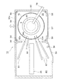
次に、液処理装置10の概略的な構成について図1乃至図3を用いて説明する。図1に示すように、本実施の形態による液処理装置10は、ウエハWが収容され、この収容されたウエハWの液処理が行われるチャンバ20と、チャンバ20に隣接して形成された待機室80と、を備えている。ここでチャンバ20内には、図2および図3に示すように、ウエハWと、ウエハWの上方に配置されたカバー機構60と、が設けられている。このうちカバー機構60は、ウエハWを上方から覆う下降位置(図2参照)と、下降位置よりも上方に位置する上昇位置(図3参照)との間で上下方向に移動自在となっている。カバー機構60は、後に詳細に説明するように、ウエハWの上面にSPM液などの薬液が吐出される際、薬液がチャンバ20内の広範囲に拡散するのを防ぐためにウエハWを上方から覆うためのものである。
Liquid Processing Apparatus Next, a schematic configuration of the
カバー機構60を上下方向に移動自在とするための具体的な手段は特には限定されないが、例えば、カバー機構60は、図2および図3に示すように、チャンバ20の外部に設けられ、上下方向に延びる支持部78cと、支持部78cに沿って上下方向に駆動される可動部78bと、一端が可動部78bに取り付けられ、他端がカバー機構60に取り付けられたアーム78aと、を有する昇降駆動機構78によって上下方向に動かされるようになっている。この場合、可動部78bを上下方向に駆動するための具体的な手段が特に限られることはなく、例えば、エアシリンダ、モータなどの公知の駆動手段が用いられ得る。またチャンバ20の側壁のうち昇降駆動機構78のアーム78aが通る領域には開口(図示せず)が形成されている。
Specific means for making the
また図2および図3に示すように、液処理装置10は、チャンバ20内の位置(後述する進出位置)と、待機室80内の位置(後述する退避位置)との間で水平方向に移動自在に設けられた遮蔽機構30をさらに備えている。遮蔽機構30は、後に詳細に説明するように、ウエハWに対して洗浄・乾燥処理を施す際、清浄ガスのダウンフローを生成してウエハWを清浄状態にするエアフード31と、エアフード31の上方に設けられた洗浄用容器32と、を有している。図3に示すように、遮蔽機構30がチャンバ20内に配置されるとき、遮蔽機構30はウエハWとカバー機構60との間に位置付けられる。このため、遮蔽機構30によって、上下方向において、ウエハWをカバー機構60から遮蔽することができる。従って、仮にSPM処理の際にSPM液の液滴や飛沫がカバー機構60に付着した場合であっても、そのようなSPM液の液滴や飛沫がウエハWに落下することを、遮蔽機構30によって遮ることができる。
As shown in FIGS. 2 and 3, the
遮蔽機構30を水平方向に移動自在とするための具体的な手段は特には限定されないが、例えば、遮蔽機構30は、図2および図3に示すように、チャンバ20の外部に設けられ、水平方向に延びる支持部35cと、支持部35cに沿って水平方向に駆動される可動部35bと、一端が可動部35bに取り付けられ、他端が遮蔽機構30に取り付けられたアーム35aと、を有する水平駆動機構35によって水平方向に動かされるようになっている。この場合、可動部35bを水平方向に駆動するための具体的な手段が特に限られることはなく、例えば、エアシリンダ、モータなどの公知の駆動手段が用いられ得る。またチャンバ20の側壁のうち水平駆動機構35のアーム35aおよび遮蔽機構30が通る領域には開口(図示せず)が形成されている。
Specific means for making the
本実施の形態によれば、ウエハWにSPM処理を施す際、カバー機構60は、SPM液により発生するヒュームがチャンバ20内の広範囲に拡散することを防ぐことができる。またウエハWに洗浄・乾燥処理を施す際、遮蔽機構30は、カバー機構60に付着した薬液の液滴や飛沫によってウエハWが汚染されることを防ぐことができる。このため本実施の形態によれば、SPM処理と洗浄・乾燥処理とを同一のチャンバ20内で実施することが可能となっている。
According to the present embodiment, when performing the SPM process on the wafer W, the
以下、このような特長を有する液処理装置10の構成について、図4A乃至図5Bを参照して詳細に説明する。図4Aおよび図4Bは、カバー機構60が下降位置にあり、かつ遮蔽機構30が退避位置にあるときの液処理装置10を示す平面図および縦断面図であり、図5Aおよび図5Bは、カバー機構60が上昇位置にあり、かつ遮蔽機構30が進出位置にあるときの液処理装置10を示す平面図および縦断面図である。
Hereinafter, the configuration of the
図4Bに示すように、液処理装置10は、ウエハWを水平状態で保持して回転させるための基板保持部21と、ウエハWの処理状況に応じて上下方向に移動可能な上述のカバー機構60と、ウエハWの処理状況に応じて水平方向に移動可能な上述の遮蔽機構30と、を備えている。また後述するように、カバー機構60には、上方からウエハWの上面にSPM液を吐出する吐出口を有する処理流体ノズル65が取り付けられている。この処理流体ノズル65は、後述するように、SPM液だけでなくDIWやガスなどのその他の処理流体をウエハWの上面に吐出する吐出口を有していてもよい。処理流体ノズル65には、処理流体ノズル65に薬液やその他の処理流体を供給する処理流体供給機構70が接続されている。
As shown in FIG. 4B, the
また図4Bに示すように、基板保持部21の周囲には、上部に開口を有し、基板保持部21を囲むように、かつ基板保持部21と一緒に回転するように設けられた回転カップ40が配設されている。この回転カップ40および上述のカバー機構60は、カバー機構60が下降位置にあるときに、カバー機構60が回転カップ40の上部の開口を覆うよう構成されている。
Further, as shown in FIG. 4B, a rotating cup is provided around the
また図4Aおよび図4Bに示すように、回転カップ40の周囲には、ウエハW、基板保持部21および回転カップ40を囲むように設けられた円筒状のカップ外周筒50が配設されている。このカップ外周筒50は、ウエハWの処理状況に応じて、図4Bに示すカップ下降位置と図5Bに示すカップ上昇位置との間で上下方向に移動可能となっている。カップ外周筒50の詳細な構造については後に説明する。
As shown in FIGS. 4A and 4B, a cylindrical cup outer
また、液処理装置10には、基板保持部21に保持されたウエハWに対してウエハWの上方から処理液やN2ガス等の流体を供給するためのノズル(進退ノズル)82aおよびこのノズル82aを支持するノズル支持アーム82が設けられている。図4Aおよび図5Aに示すように、1つの液処理装置10には複数(具体的には例えば4つ)のノズル支持アーム82が設けられており、各ノズル支持アーム82の先端にノズル82aが設けられている。また、図4Bおよび図5Bに示すように、各ノズル支持アーム82にはアーム支持部84が設けられており、各アーム支持部84はアーム駆動機構(図示せず)によって図4Bおよび図5Bにおける左右方向に駆動されるようになっている。このことにより、各ノズル支持アーム82は、ノズル82aがチャンバ20内に進出したノズル進出位置と、ノズル82aがチャンバ20から退避したノズル退避位置との間で水平方向に直線運動を行うようになっている(図4A乃至図5Bにおける各ノズル支持アーム82に設けられた矢印参照)。また、図4Bおよび図5Bに示すように、各ノズル支持アーム82には表面処理液供給管82mが設けられており、各表面処理液供給管82mは表面処理液供給部89に接続されている。そして、表面処理液供給部89から各表面処理液供給管82mを介して各ノズル支持アーム82のノズル82aに処理液やN2ガス等の流体が供給されるようになっている。
Further, the
図4Aおよび図4Bに示すように、各ノズル支持アーム82および上述の遮蔽機構30は、ウエハWの処理状況に応じて、チャンバ20に隣接して形成された待機室80において待機するよう制御される。
As shown in FIGS. 4A and 4B, each
なお、水平方向に移動可能な上述のノズル82aだけでなく、図4Bに示すように、チャンバ20内に固定された固定ノズル92がさらに設けられていてもよい。この固定ノズル92は、カップ外周筒50よりも内側に位置するよう設けられている。固定ノズル92は、後述するように、遮蔽機構30が水平方向に移動している間にウエハWに対してDIWなどの処理液を供給するよう構成されている。なお図4Bにおいては、固定ノズル92が後述するドレインカップ42に取り付けられている例が示されている。しかしながら、固定ノズル92が取り付けられる部材がドレインカップ42に限られることはなく、カップ外周筒50よりも内側に位置する様々な部材に取り付けられ得る。
In addition to the above-described
また、図4A乃至図5Bに示すように、チャンバ20の底部におけるカップ外周筒50の外側には排気部56が設けられており、この排気部56によりチャンバ20内の雰囲気の排気が行われる。具体的には、排気部56により、待機室80内の雰囲気がカップ外周筒50内に入り込むことが抑止される。また、この排気部56により、カップ外周筒50内の雰囲気が待機室80に出てしまうことが抑止される。
As shown in FIGS. 4A to 5B, an
また、図4A乃至図5Bに示すように、待機室80の底部には排気部58が設けられており、この排気部58により待機室80内の雰囲気の排気が行われる。例えば、各ノズル支持アーム82を駆動する際に発生しうるパーティクルを排気部58により排出することができるようになっている。
As shown in FIGS. 4A to 5B, an
また、図4Aおよび図5Aに示すように、液処理装置10のチャンバ20および待機室80の出入口にはそれぞれメンテナンス用のシャッター57、59が設けられている。チャンバ20および待機室80にそれぞれメンテナンス用のシャッター57、59が設けられていることにより、チャンバ20内や待機室80内の機器を個別にメンテナンスすることが可能となる。
As shown in FIGS. 4A and 5A,
また、図4Aおよび図5Aに示すように、チャンバ20の側壁には、搬送アーム104によりチャンバ20内へウエハWを搬入したりチャンバ20からウエハWを搬出したりするための開口94aが設けられている。この開口94aには、当該開口94aを開閉するためのシャッター94が設けられている。
As shown in FIGS. 4A and 5A, the side wall of the
次に、液処理装置10の各構成要素の詳細について以下に説明する。
Next, details of each component of the
(基板保持部)
はじめに図6を参照して、基板保持部21について説明する。図6は、液処理装置10の各構成要素のうち、基板保持部21およびその周辺に位置する構成要素を示す縦断面図である。
(Substrate holder)
First, the
図6に示すように、基板保持部21は、ウエハWを保持するための円板形状の保持プレート26と、保持プレート26の上方に設けられた円板形状のリフトピンプレート22とを備えている。リフトピンプレート22の上面には、ウエハWを下方から支持するためのリフトピン23が周方向に等間隔で3つ設けられている。なお、図6では2つのリフトピン23のみを表示している。また、リフトピンプレート22にはピストン機構24が設けられており、このピストン機構24によりリフトピンプレート22が昇降するようになっている。より具体的には、搬送アーム104(図1参照)によりウエハWをリフトピン23上に載置したりリフトピン23上からウエハWを取り出したりするときには、ピストン機構24によりリフトピンプレート22が図6に示すような位置から上方に移動させられ、このリフトピンプレート22は回転カップ40よりも上方に位置するようになる。一方、チャンバ20内でウエハWの液処理を行う際には、ピストン機構24によりリフトピンプレート22が図6に示すような下降位置に移動させられ、ウエハWの周囲に回転カップ40が位置するようになる。
As shown in FIG. 6, the
保持プレート26には、ウエハWを側方から支持するための保持部材25が周方向に等間隔で3つ設けられている。なお、図6では2つの保持部材25のみを表示している。各保持部材25は、リフトピンプレート22が上方位置から図6に示すような下降位置に移動したときにこのリフトピン23上のウエハWを支持し、このウエハWをリフトピン23からわずかに離間させるようになっている。
The holding
保持プレート26には、図6に示すように上述の回転カップ40が取り付けられており、これによって、回転カップ40は、保持プレート26と一体的に回転することができる。この回転カップ40は、図6に示すように、保持プレート26の各保持部材25により支持されたウエハWを側方から囲うよう設けられている。このため、回転カップ40は、ウエハWの液処理を行う際にこのウエハWから側方に飛散した処理液を受けることができる。
As shown in FIG. 6, the above-described
(ドレインカップおよび案内カップ)
また、回転カップ40の周囲には、ドレインカップ42、第1案内カップ43、第2案内カップ44および第3案内カップ45が上方から順に設けられている。ドレインカップ42および各案内カップ43、44、45はそれぞれリング状に形成されている。ドレインカップ42および各案内カップ43,44,45は各々、上部に開口を有している。ここで、ドレインカップ42はチャンバ20において固定されている。一方、各案内カップ43、44、45にはそれぞれ昇降シリンダ(図示せず)が連結されており、これらの案内カップ43、44、45は対応する昇降シリンダにより互いに独立して昇降自在となっている。
(Drain cup and guide cup)
In addition, a
図6に示すように、ドレインカップ42や各案内カップ43、44、45の下方には、第1処理液回収用タンク46a、第2処理液回収用タンク46b、第3処理液回収用タンク46cおよび第4処理液回収用タンク46dがそれぞれ設けられている。そして、各案内カップ43、44、45の上下方向における位置により、ウエハWの液処理を行う際にこのウエハWから側方に飛散した処理液が、この処理液の種類に基づいて、4つの処理液回収用タンク46a、46b、46c、46dのうちいずれか一つの処理液回収用タンクに選択的に送られるようになっている。具体的には、全ての案内カップ43、44、45が全て上方位置にあるときには(図6に示すような状態)、ウエハWから側方に飛散した所定の処理液が第4処理液回収用タンク46dに送られるようになっている。一方、第3案内カップ45のみが下方位置にあるときには、ウエハWから側方に飛散した所定の処理液、例えば後述するSC−1液が第3処理液回収用タンク46cに送られるようになっている。また、第2案内カップ44および第3案内カップ45が下方位置にあるときには、ウエハWから側方に飛散した所定の処理液、例えば後述するDHF液が第2処理液回収用タンク46bに送られるようになっている。また、全ての案内カップ43、44、45が下方位置にあるときには、ウエハWから側方に飛散した所定の処理液、例えばSPM液が第1処理液回収用タンク46aに送られるようになっている。
As shown in FIG. 6, below the
また、図6に示すように、第4処理液回収用タンク46dの内側には排気部48が設けられている。そして、各案内カップ43、44、45の上下方向における位置が所定の位置となることにより、ウエハWの周囲の雰囲気が、排気部48により排気されるようになっている。この排気部48は、ウエハWの周囲の雰囲気だけでなく、チャンバ20内の雰囲気を排気し、これによってチャンバ20内の雰囲気を置換することもできる。
Further, as shown in FIG. 6, an
(カップ外周筒)
また図6に示すように、ドレインカップ42や各案内カップ43、44、45の周囲には、上述のカップ外周筒50が設けられている。このカップ外周筒50について、図7を参照して詳細に説明する。図7は、カップ外周筒50を示す斜視図である。
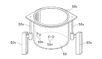
(Cup outer cylinder)
As shown in FIG. 6, the cup outer
図7に示すように、カップ外周筒50の側面には、ノズル支持アーム82が通過可能な側部開口50mが、ノズル支持アーム82の本数に応じて設けられている。例えばノズル支持アーム82が4本の場合、4つの側部開口50mが設けられている。また、カップ外周筒50の上部には、このカップ外周筒50を支持するための支持部材50aが連結されており、支持部材50aには当該支持部材50aを昇降させる駆動機構50bが設けられている。そして、駆動機構50bにより支持部材50aを昇降させることにより、この支持部材50aに支持されるカップ外周筒50も昇降するようになっている。
As shown in FIG. 7,
またカップ外周筒50の上部には、開口(上部開口)が形成されている。この上部開口は、カップ外周筒50がカップ上昇位置にある時、進出位置にある遮蔽機構30のエアフード31に近接するまたは接するように構成されている。すなわち、遮蔽機構30が進出位置にある時にエアフード31およびカップ外周筒50の内側に形成される空間は、外部から隔離される。後述するように、ノズル82aからDIWなどの処理液をウエハWに吐出することにより実施される様々な処理は、このようにエアフード31とカップ外周筒50とによって外部から隔離された条件の下で実施される。以下の説明において、エアフード31およびカップ外周筒50の内側に形成される、外部から隔離された空間のことを「処理空間」と称する。
An opening (upper opening) is formed in the upper part of the cup outer
上述のような処理空間を形成することにより得られる利点として、主に以下の2つの利点が考えられる。1つは、外部から隔離されていることにより、処理空間内の雰囲気が外部に出るのを防ぐことができ、かつ、外部の雰囲気が処理空間内に入るのを防ぐことができるという利点である。もう1つは、処理空間が閉空間となっていることにより、処理が実施される空間の容積を小さくすることができ、これによって、処理の効率を上げることができるという利点である。例えば、処理の際に処理空間内の清浄ガスへの置換効率を上げることができるという利点である。 As advantages obtained by forming the processing space as described above, the following two advantages are mainly conceivable. One is an advantage that the atmosphere in the processing space can be prevented from going outside by being isolated from the outside, and the outside atmosphere can be prevented from entering the processing space. . The other is that the processing space is a closed space, so that the volume of the space in which the processing is performed can be reduced, thereby increasing the processing efficiency. For example, there is an advantage that the efficiency of replacement with clean gas in the processing space can be increased during processing .
なお、図5Bに示す液処理装置10において、チャンバ20内におけるカップ外周筒50の内部の領域はクリーンルームに対して微陽圧となっており、一方、チャンバ20内におけるカップ外周筒50の外部の領域はクリーンルームに対して微陰圧となっている。このため、チャンバ20内において、カップ外周筒50の内部の領域の気圧はカップ外周筒50の外部の領域の気圧よりも高くなっている。
In the
また図7に示すように、カップ外周筒50の上部には、遮蔽機構30が進出位置にある時にカップ外周筒50とエアフード31との間に介在されるシール部材が取り付けられている。このようなシール部材を設けることにより、エアフード31およびカップ外周筒50の内側に形成される処理空間をより強固に外部から隔離することができる。シール部材の具体的な構成は特には限定されないが、例えばシール部材は、図7に示すように、カップ外周筒50の上面に取り付けられたOリング50cからなっている。
Further, as shown in FIG. 7, a seal member interposed between the cup outer
(カバー機構)
次に、カバー機構60について詳細に説明する。図4Bおよび図5Bに示すように、カバー機構60は、少なくともウエハWの直径より大きい直径を有する円板状の天板61を有している。この天板61は、好ましくは、上述の回転カップ40の上部に形成された開口およびドレインカップ42の上部に形成された開口を完全に覆うのに十分な形状および寸法を有している。例示された実施形態においては、天板61は、ドレインカップ42の上部に形成された開口の直径よりやや大きい直径を有する円板状の形状を有している。
(Cover mechanism)
Next, the
図8Aおよび図8Bは、それぞれ天板61を示す平面図および底面図である。図8Aおよび図8Bに示すように、天板61には、ウエハWの上面にSPM液を吐出する吐出口を有する処理流体ノズル65が組み込まれている。この処理流体ノズル65は、図8Bに示すように、天板61の中心部に設けられたセンターノズル67と、天板61の中心部から天板61の周縁部に向かって延びるバーノズル(多連ノズル)66と、を含んでいる。このうちセンターノズル67は、天板61の中心部に設けられ、ウエハWの上面にSPM液を吐出するセンター吐出口67aを含んでいる。またバーノズル66は、天板61の中心部から天板61の周縁部の間に配列され、ウエハWの上面にSPM液を吐出する複数の吐出口66aを含んでいる。すなわち各吐出口66aは、ウエハWの中心部に対向する位置からウエハWの周縁部に対向する位置の間に配列されている。このような処理流体ノズル65の構造の詳細については後述する。
8A and 8B are a plan view and a bottom view showing the
図8Bに示すように、センターノズル67のセンター吐出口67aの近傍には、不活性ガスをウエハWの上面に吹き付けるガス吐出口68aと、高温に熱せられた純水(HOT−DIW)をウエハWの上面に吐出する洗浄液吐出口68bと、がさらに設けられていてもよい。
As shown in FIG. 8B, in the vicinity of the
(処理流体供給機構)
また図8Aに示すように、天板61の近傍には、処理流体ノズル65にSPM液、不活性ガスおよびHOT−DIWを供給する処理流体供給機構70が設けられている。以下、図8Aおよび図9Aを参照して、処理流体供給機構70について詳細に説明する。
(Processing fluid supply mechanism)
Further, as shown in FIG. 8A, a processing
[SPM液]
はじめに、処理流体供給機構70から処理流体ノズル65へ供給されるSPM液について説明する。SPM液は、硫酸(第1の薬液)と過酸化水素水(第2の薬液)とを混合することにより得られる混合薬液である。好ましくは、硫酸と過酸化水素との混合は、処理流体ノズル65の近傍若しくは処理流体ノズル65の内部において実施される。
[SPM solution]
First, the SPM liquid supplied from the processing
[供給源および供給管]
図8Aに示すように、処理流体供給機構70は、硫酸(第1の薬液)を収容する第1供給源71と、硫酸を第1供給源71から処理流体ノズル65に供給する第1供給管72と、過酸化水素水(第2の薬液)を収容する第2供給源73と、過酸化水素水を第2供給源73から処理流体ノズル65に供給する第2供給管74と、を有している。このうち第1供給管72は、硫酸をバーノズル66に供給するバーノズル用第1供給管72aと、硫酸をセンターノズル67に供給するセンターノズル用第1供給管72bと、からなっている。また第2供給管74は、過酸化水素水をバーノズル66に供給するバーノズル用第2供給管74aと、過酸化水素水をセンターノズル67に供給するセンターノズル用第2供給管74bと、からなっている。各供給源71,73は、チャンバ20の内部または外部の所定の位置に固定されている。
[Supply source and supply pipe]
As shown in FIG. 8A, the processing
第1供給源71からバーノズル用第1供給管72aを介してバーノズル66に供給される硫酸の流量、および第1供給源71からセンターノズル用第1供給管72bを介してセンターノズル67に供給される硫酸の流量は、互いに独立に制御可能となっている。同様に、第2供給源73からバーノズル用第2供給管74aを介してバーノズル66に供給される過酸化水素水の流量、および第2供給源73からセンターノズル用第2供給管74bを介してセンターノズル67に供給される過酸化水素水の流量は、互いに独立に制御可能となっている。
The flow rate of sulfuric acid supplied from the
また処理流体供給機構70は、不活性ガス供給源(図示せず)からの不活性ガスをガス吐出口68aに供給するガス供給管75aと、HOT−DIW供給源(図示せず)からのHOT−DIWを洗浄液吐出口68bに供給する洗浄液供給管75bと、をさらに含んでいてもよい。
Further, the processing
各供給管72a,72b,74a,74b,75a,75bは、上下方向におけるカバー機構60の移動に追従できるよう、所定の柔軟性を有する材料から構成されている。また後述するように、処理流体ノズル65に供給される硫酸は、140〜200度の高温に加熱された状態で第1供給管72を通る。このため、第1供給管72のバーノズル用第1供給管72aおよびセンターノズル用第1供給管72bを構成する材料は、所定の柔軟性を有するとともに、所定の耐熱性を有する材料から構成されている。例えば、PFA(テトラフルオロエチレン・パーフルオロアルキルビニルエーテル共重合体)から構成されている。
Each of the
図9Aは、カバー機構60および処理流体供給機構70を側方から見た場合を示す図である。図9Aに示すように、各供給管72a,72b,74a,74b,75a,75bは、略水平方向に延びている。ここで「略水平に延びている」とは、例えば図9Aにおいてバーノズル用第1供給管72aに関して示されているように、第1供給源71と処理流体ノズル65との間において、バーノズル用第1供給管72aの水平方向における延在範囲l1が上下方向における延在範囲l2よりも大きくなっていることを意味している。
FIG. 9A is a diagram illustrating a case where the
なお図8Aに示す例においては、各供給管72a,72b,74a,74b,75a,75bが昇降駆動機構78のアーム78aに部分的に固定されている例を示した。しかしながら、各供給源から処理流体ノズル65に至る供給管72a,72b,74a,74b,75a,75bの引き回し方法が特に限られることはなく、各供給源の配置などに応じて適宜設定され得る。
In the example shown in FIG. 8A, an example is shown in which each
(処理流体ノズル)
次に図9Bおよび図9Cを参照して、処理流体ノズル65について詳細に説明する。図9Bは、天板61に組み込まれた処理流体ノズル65を下方から見た場合を示す底面図である。
(Processing fluid nozzle)
Next, the
[バーノズル]
はじめにバーノズル66について説明する。図9Bにおいて破線で示すように、バーノズル66には、硫酸を供給するバーノズル用第1供給管72aに連通している流体通路(硫酸通路)66bと、過酸化水素水を供給するバーノズル用第2供給管74aに連通している流体通路(過酸化水素水通路)66cと、が形成されている。図9Bに破線で示すように、硫酸通路66bおよび過酸化水素水通路66cは、天板61の中心部側から天板61の周縁部側に至るまで、バーノズル66の長手方向に沿って、水平に、かつ互いに平行に延びている。
[Bar nozzle]
First, the
次に図9Cを参照して、バーノズル66の吐出口66aがSPM液を吐出するための機構について説明する。図9Cは図9BにおけるIXc−IXc線に沿ったバーノズル66の内部構造を示す断面図である。
Next, with reference to FIG. 9C, a mechanism for the
図9Cに示すように、バーノズル66においては、各吐出口66aに対応して、硫酸通路66bに1つの硫酸吐出路66dが、過酸化水素水通路66cに一つの過酸化水素水吐出路66eがそれぞれ接続されている。また図9Cに示すように、硫酸吐出路66dが終端する吐出口66aよりも手前の位置で、過酸化水素水吐出路66eが硫酸吐出路66dに合流している。従って、各吐出口66aから、硫酸と過酸化水素水とを混合することにより生成された直後のSPM液が吐出される。このように各吐出口66aの近傍において硫酸と過酸化水素水とを混合することにより、混合に起因する化学反応によって温度上昇した直後のSPM液を各吐出口66aから吐出することができる。
As shown in FIG. 9C, in the
[センターノズル]
次にセンターノズル67について説明する。センターノズル67においても、バーノズル66の場合と同様に、硫酸を供給するセンターノズル用第1供給管72bに連通している硫酸通路(図示せず)と、過酸化水素水を供給するセンターノズル用第2供給管74bに連通している過酸化水素水通路とが設けられている。そして、センター吐出口67aの近傍で硫酸と過酸化水素水とを混合することにより生成されたSPM液が、センター吐出口67aから吐出されるようになっている。
[Center nozzle]
Next, the
(ヒーター)
次に、天板61に設けられるヒーターについて説明する。SPM液は、ウエハWの上面に設けられたレジスト膜を除去するためにウエハWの上面に吐出される。この際、SPM液がレジスト膜を除去する能力は、SPM液の温度が高いほど高められる。このため、SPM処理の際、ウエハWおよびレジスト膜の周辺環境を加熱することにより、SPM処理温度が高められていることが好ましい。例えば、ウエハWおよびレジスト膜の周辺環境の温度を各吐出口66aから吐出されるSPM液の温度よりも高くしておくことが好ましい。これによって、ウエハW上に供給されたSPM液の温度をさらに高めることができ、SPM液がレジスト膜を除去する能力を向上させることができる。このような加熱を実現するため、本実施の形態においては、周囲環境を介してウエハWおよびレジスト膜を加熱するためのヒーターがカバー機構60の天板61に設けられている。以下、このようなヒーターについて、図8Bおよび図9Dを参照して説明する。
(heater)
Next, the heater provided in the
図8Bにおいて破線で示すように、天板61には、ウエハWを加熱するためのヒーター、例えばLEDランプ63が組み込まれている。図9Dは、天板61を示す縦断面図である。図9Dに示すように、このLEDランプ63は、天板61の内部に設けられている。例示された実施形態においては、複数のLEDランプ63を有する1つのLEDランプアレイが設けられている。LEDランプ63は、ウエハWを加熱するために適した波長、具体的には例えば880nmの波長の光を放射するものが用いられている。またLEDランプ63は、880nmの波長の光を良く透過し、かつ耐食性の高い石英やテフロン(登録商標)からなるカバー64に覆われて保護されている。
As indicated by a broken line in FIG. 8B, a heater for heating the wafer W, for example, an
なお図8Bおよび図9Dにおいては、ウエハWのサイズに概ね等しいサイズの1つのLEDランプアレイが設けられている例が示されているが、これに限定されるものではなく、ウエハ中央部に対向する位置に1または複数のLEDランプアレイを設け、ウエハ周縁部に対向する位置に1または複数のLEDランプアレイを設け、ウエハ中央部とウエハ周縁部との間のウエハ中間部に対向する位置に1または複数のLEDランプアレイを設けてもよい。この場合、これらの各LEDランプアレイを個別に制御することにより、ウエハWの部位毎に温度制御をする(いわゆるゾーン制御)ことも可能である。なお、ウエハWの回転に伴い生じる気流によりウエハWの外周部が冷えやすい傾向にあるため、LEDの出力もしくはLEDランプの数(発光素子数)を外周部ほど多くすることが好ましい。これによって、ウエハWの全面を均一に加熱することができる。 8B and 9D show an example in which one LED lamp array having a size substantially equal to the size of the wafer W is provided. However, the present invention is not limited to this and faces the wafer center. One or a plurality of LED lamp arrays are provided at a position to be opposed to each other, one or a plurality of LED lamp arrays are provided at a position opposed to the wafer peripheral edge, and a position opposed to the wafer intermediate portion between the wafer central portion and the wafer peripheral edge is provided. One or more LED lamp arrays may be provided. In this case, it is also possible to control the temperature for each part of the wafer W (so-called zone control) by individually controlling each of these LED lamp arrays. Since the outer peripheral portion of the wafer W tends to be easily cooled by the air flow generated as the wafer W rotates, it is preferable to increase the number of LED outputs or the number of LED lamps (the number of light emitting elements) as the outer peripheral portion. Thereby, the entire surface of the wafer W can be heated uniformly.
LEDランプ63の上方において、天板61の内部には、熱に弱いLEDランプ63を冷却して保護するために、冷媒通路62aが設けられていてもよい。冷媒通路62aは、平面視で、螺旋状または同心円状等に配置することができる。冷媒通路62aには、冷媒供給源、例えば冷却水供給源(図示せず)に接続された冷媒供給管(図示せず)が接続されている。
Above the
(遮蔽機構)
次に、遮蔽機構30について詳細に説明する。はじめに、遮蔽機構30のエアフード31について説明する。エアフード31は、クリーンエア等の清浄ガスをダウンフローでウエハWの上面に吹き付けるよう構成されている。図10は、エアフード31を示す断面図である。エアフード31は、FFU(ファンフィルタユニット)33と、FFU33の下方に設けられ、多数の孔34aが形成されたパンチングプレート34と、を含んでいる。このうちFFU33の内部には、図示はしないが、空気を送風する送風機、空気を清浄化してクリーンエアにするフィルタ等が設けられている。またパンチングプレート34の各孔34aは、パンチングプレート34の全域にわたって均等に分布するよう構成されている。このため、FFU33によって生成されるクリーンエアが、パンチングプレート34の各孔34aによって整流される。このような構成のエアフード31を用いることにより、クリーンエアの整流されたダウンフローをウエハWの上面に対して吹き付けることができる。なお、エアフード31において用いられる清浄ガスがクリーンエアに限られることはなく、N2ガス(窒素ガス)等の不活性ガスが用いられてもよい。
(Shielding mechanism)
Next, the
(洗浄用容器)
また図4Bおよび図5Bに示すように、エアフード31の上方には、エアフード31とともに水平方向に移動するとともに、洗浄液(カバー機構用の洗浄液、例えばDIW)などの液体を収容することができる収容部32aが形成された洗浄用容器32が取り付けられていてもよい。このような洗浄用容器32をエアフード31の上方に設けることにより、後述するように、遮蔽機構30が進出位置にある際、エアフード31の上方にあるカバー機構60の天板61を洗浄用容器32の洗浄液によって洗浄することが可能となる。また洗浄用容器32は、上述のカバー機構60の天板61よりも大きい直径からなる円形の輪郭を有している。このため、エアフード31とともに洗浄用容器32を進出位置に配置することにより、カバー機構60の天板61に付着している液滴などがウエハWに落下することを遮ることができる。
(Cleaning container)
As shown in FIGS. 4B and 5B, the
洗浄用容器32の収容部32aには、収容部32aに収容された洗浄液などの液体を適切に排出するための排水管(図示せず)が接続されていてもよい。排水管の具体的な構成が特に限られることはなく、例えば排水管は、エアフード31および洗浄用容器32に追従して水平方向に移動または伸縮するよう構成されていてもよい。若しくは、排水管は、エアフード31および洗浄用容器32が進出位置または退避位置のいずれかにある際に収容部32aと連通するよう、チャンバ20内または待機室80内の所定の位置に固定されていてもよい。
A drainage pipe (not shown) for appropriately discharging a liquid such as a cleaning liquid stored in the
(コントローラ)
液処理装置10は、その全体の動作を統括制御するコントローラ200を有している。コントローラ200は、液処理装置10の全ての機能部品(例えば基板保持部21、ピストン機構24、遮蔽機構30の水平駆動機構35、カップ外周筒50の駆動機構50b、カバー機構60の昇降駆動機構78、処理流体供給機構70など)の動作を制御する。コントローラ200は、ハードウエアとして例えば汎用コンピュータと、ソフトウエアとして当該コンピュータを動作させるためのプログラム(装置制御プログラムおよび処理レシピ等)とにより実現することができる。ソフトウエアは、コンピュータに固定的に設けられたハードディスクドライブ等の記憶媒体に格納されるか、或いはCDROM、DVD、フラッシュメモリ等の着脱可能にコンピュータにセットされる記憶媒体に格納される。このような記憶媒体が参照符号201で示されている。プロセッサ202は必要に応じて図示しないユーザーインターフェースからの指示等に基づいて所定の処理レシピを記憶媒体201から呼び出して実行させ、これによってコントローラ200の制御の下で液処理装置10の各機能部品が動作して所定の処理が行われる。コントローラ200は、図1に示す液処理システム全体を制御するシステムコントローラであってもよい。
(controller)
The
次に、上述した液処理装置10を用いて、ウエハWの上面にある不要なレジスト膜を除去する洗浄処理の一連の工程について説明する。
Next, a series of cleaning processing steps for removing an unnecessary resist film on the upper surface of the wafer W using the above-described
<ウエハ搬入および設置工程>
はじめに、カバー機構60が上昇位置に配置されていることを確認する。次に、水平駆動機構35によって遮蔽機構30をチャンバ20内へ水平移動させる。これによって、図11(a)に示すように、遮蔽機構30が、カバー機構60とウエハWとの間でウエハWをカバー機構60から遮蔽する進出位置に配置される。この状態で、遮蔽機構30のエアフード31によってクリーンエア等の清浄ガスのダウンフローが生成される。
<Wafer loading and installation process>
First, it is confirmed that the
その後、基板保持部21におけるリフトピンプレート22および処理液供給管28を図6に示す位置から上方に移動させ、また、シャッター94を移動させて開口94aを形成する。次に、液処理装置10の外部からウエハWが搬送アーム104により開口94aを介してチャンバ20内に搬送され、このウエハWがリフトピンプレート22のリフトピン23上に載置される。この際、カップ外周筒50は図6に示すようなカップ下降位置に位置している。また、各ノズル支持アーム82はチャンバ20から退避したノズル退避位置に位置している。すなわち、各ノズル支持アーム82は待機室80内で待機している。また、エアフード31からクリーンエア等の清浄ガスが常にダウンフローで送られ、この清浄ガスが排気部48により排気されることにより、チャンバ20内の雰囲気の置換が行われる。
Thereafter, the
次に、リフトピンプレート22および処理液供給管28を下方に移動させ、これらのリフトピンプレート22および処理液供給管28を図6に示すような下方位置に位置させる。この際に、保持プレート26に設けられた各保持部材25が、リフトピン23上のウエハWを支持し、このウエハWをリフトピン23からわずかに離間させる。
Next, the
なお、ウエハWは、その「表面」(パターンが形成される面)が「上面」となり、その「裏面」(パターンが形成されない面)が「下面」となっている状態で、液処理装置10内に搬入される。 Note that the wafer W has a “front surface” (surface on which a pattern is formed) as an “upper surface” and a “back surface” (surface on which no pattern is formed) as a “lower surface”. It is carried in.
<SPM洗浄処理>
次に、遮蔽機構30のエアフード31からのクリーンエアのダウンフローを停止させ、その後、遮蔽機構30をチャンバ20の外部へ向けて水平移動させる。これによって、図11(b)に示すように、遮蔽機構30がチャンバ20の外部に位置する退避位置に配置される。次に、上昇位置で待機していたカバー機構60を下降させて、ウエハWの近傍においてウエハWの上方を覆う下降位置に移動させる。この状態で、基板保持部21の保持プレート26を回転させる。これに伴って、各保持部材25により支持されているウエハWも回転する。
<SPM cleaning process>
Next, the downflow of clean air from the
ウエハWの回転開始と同時またはその後に、カバー機構60の天板61に取り付けられたLEDランプ63を点灯させ、これによって、ウエハWの上面(デバイス形成面)からウエハWを加熱する。このとき例えばウエハWは200℃程度に加熱される。ウエハWが所定温度まで昇温したら、第1供給源71からバーノズル用第1供給管72aに200℃程度に加熱した硫酸を供給し、かつ、第2供給源73からバーノズル用第2供給管74aに常温の過酸化水素水を供給する。供給された硫酸および過酸化水素水は、図9Cに示すように、バーノズル66の各吐出口66aの直前で混合され、SPM液としてウエハWの上面に向けて吐出される。同様に、第1供給源71からセンターノズル用第1供給管72bに200℃程度に加熱した硫酸を供給し、かつ、第2供給源73からセンターノズル用第2供給管74bに常温の過酸化水素水を供給する。供給された硫酸および過酸化水素水は、センターノズル67のセンター吐出口67aの直前で混合され、SPM液としてウエハWの上面の中心部に向けて吐出される。
At the same time as or after the start of rotation of the wafer W, the
なお、硫酸および過酸化水素水が混合される際に反応熱により温度が上昇する。各吐出口66aおよびセンター吐出口67aから吐出されるSPM液の温度は200〜250℃程度となっている。供給されたSPM液により、ウエハWのレジスト膜が剥離される。なお、ウエハ温度より低い温度のSPM液がウエハWに掛かるとウエハ温度が下がるので、SPM液を間欠的に吐出してウエハ温度の低下を防止してもよい。
The temperature rises due to reaction heat when sulfuric acid and hydrogen peroxide are mixed. The temperature of the SPM liquid discharged from each
除去されたレジスト膜および反応生成物は、SPM液と一緒に遠心力によりウエハWの上面上を半径方向外側に流れ、ウエハWの外側に流出し、回転カップ40により受け止められて下方に向きを変える。その後、SPM液は、上述の第1処理液回収用タンク46aに送られる。
The removed resist film and reaction product flow together with the SPM solution on the upper surface of the wafer W in the radial direction by centrifugal force, flow out to the outside of the wafer W, and are received by the rotating
このときウエハWの周囲にヒュームが発生するが、ウエハWの上方および回転カップ40の上部の開口がカバー機構60の天板61によって覆われているため、天板61の上方のチャンバ20内にヒュームが拡散することを防ぐことができる。ヒュームは工場排気系に接続された(すなわち微陰圧状態にある)排液管すなわち負圧空間に吸い込まれ、SPM液から分離されて排気部48から排出される。
At this time, fume is generated around the wafer W, but the opening above the wafer W and the upper portion of the
<第1のDIWリンス処理>
SPM洗浄処理を所定時間実行した後、各吐出口66aおよびセンター吐出口67aからのSPM液の吐出を停止し、また、LEDランプ63によるウエハWの加熱を停止する。次いで、引き続きウエハWを回転させたまま、HOT−DIW供給源(図示せず)から洗浄液供給管75bに比較的大流量(例えば毎分1500ml)で高温(例えば約80度)のDIW(以下、HOT−DIW)を供給し、天板61の中心部近傍にある洗浄液吐出口68bからHOT−DIWをウエハWの中心部に向けて吐出させる。これによって、ウエハWの上面上に残っているSPM液やレジストの残渣などが、ウエハWの上面上を半径方向外側に流れるHOT−DIWにより洗い流される。HOT−DIWの排液は、SPM液の場合と同様に第1処理液回収用タンク46aに送られる。なお、この時も引き続きウエハWの上方および回転カップ40の上部の開口がカバー機構60によって覆われているため、チャンバ20内にヒュームが拡散することを防ぐことができる。
<First DIW rinse treatment>
After executing the SPM cleaning process for a predetermined time, the discharge of the SPM liquid from each
<第2のDIWリンス処理>
次に、下降位置にあるカバー機構60を上昇させて上昇位置に配置し、その後、遮蔽機構30をチャンバ20内へ水平移動させる。これによって、図11(c)に示すように、遮蔽機構30が、カバー機構60とウエハWとの間でウエハWをカバー機構60から遮蔽する進出位置に配置される。なお、遮蔽機構30が移動している間、固定ノズル92がウエハWの上面に向けてDIWなどの処理液を吐出していてもよい。これによって、遮蔽機構30が移動している間にウエハWの上面に不要な液やパーティクルが付着することを防ぐことができる。
<Second DIW rinse treatment>
Next, the
次に、カップ外周筒50を上昇させ、カップ外周筒50を図11(d)に示すようなカップ上昇位置に配置する。この際、カップ外周筒50とエアフード31とがOリング50cを介して接するよう、カップ外周筒50が上昇する。これによって、エアフード31およびカップ外周筒50の内側に形成される空間が、外部から強固に隔離される。その後、待機室80で待機している4つのノズル支持アーム82のうちDIWを供給するためのノズル82aを支持するノズル支持アーム82を、カップ外周筒50の側部開口50mを通して、チャンバ20内のノズル進出位置へ進出させる。その後、エアフード31により、クリーンエア等の清浄ガスをダウンフローでウエハWの上面に吹き付ける。
Next, the cup outer
次に、引き続きウエハWを回転させたまま、ノズル82aから低温(例えば約20度)のDIWをウエハWの上面に向けて吐出させる。これによって、ウエハWの上面上にSPM液やレジストの残渣などが残っていたとしても、これらSPM液やレジストの残渣などをより確実に洗い流すことができ、かつ、ウエハWを冷却することができる。
Next, while the wafer W is continuously rotated, DIW at a low temperature (for example, about 20 degrees) is discharged from the
<スピン乾燥処理>
第2のDIWリンス処理を所定時間実行した後、ノズル82aからのDIWの吐出を停止する。次いで、引き続きウエハWを回転させたまま(回転速度を増大させることが好ましい)、エアフード31により、クリーンエア等の清浄ガスをダウンフローでウエハWの上面に吹き付ける。これにより、ウエハWの上面上に残留していたDIWが遠心力により振り切られるとともに、清浄ガスにより乾燥が促進される。
<Spin drying process>
After the second DIW rinse process is executed for a predetermined time, the discharge of DIW from the
<ウエハ搬出工程>
スピン乾燥処理が終了したら、ウエハWの回転を停止させ、そして、ノズル82aを水平移動させて待機室80内のノズル退避位置へ戻す。またカップ外周筒50を下降させてカップ下降位置に戻す。なお、エアフード31からはクリーンエアが引き続きダウンフローでウエハWの上面に吹き付けられている。
<Wafer unloading process>
When the spin drying process is completed, the rotation of the wafer W is stopped, and the
その後、基板保持部21におけるリフトピンプレート22および処理液供給管28を図6に示す位置から上方に移動させる。この際に、保持プレート26の保持部材25により支持されたウエハWがリフトピンプレート22のリフトピン23上に受け渡される。次に、シャッター94を移動させて開口94aを形成する。その後、エアフード31によりクリーンエアのダウンフローが生成されている中で、液処理装置10の外部から開口94aを介して、搬送アーム104によりウエハWを取り出す。搬送アーム104により取り出されたウエハWは液処理装置10の外部に搬送される。このようにして、一連のウエハWの液処理が完了する。
Thereafter, the
上記の実施形態によれば、ウエハWの上面上のレジスト膜を高温SPM洗浄処理により除去する際、ウエハWの上方がカバー機構60の天板61によって覆われている。このため、ウエハW上で発生したSPM液および被処理物体由来のガスまたはミストからなるヒュームがウエハWの上方に拡散することを防止することができる。このため、ヒュームがウエハWの上方のチャンバ20の内壁およびチャンバ20内の部品を汚染しあるいは腐食させ、ウエハ汚染の原因物質を発生させることを防止することができる。
さらに、SPM洗浄処理の後に実施される第2のDIWリンス処理およびスピン乾燥処理の際、カバー機構60とウエハWとの間には、チャンバ20内へ進出されたエアフード31が配置されている。このエアフード31の上方には、カバー機構60の天板61よりも大きい直径からなる円形の輪郭を有する洗浄用容器32が設けられている。このため、第2のDIWリンス処理およびスピン乾燥処理の際、天板61に付着している可能性のあるSPM液の液滴や飛沫がウエハW上に落下することを防ぐことができる。
According to the above embodiment, when the resist film on the upper surface of the wafer W is removed by the high temperature SPM cleaning process, the upper portion of the wafer W is covered with the
Further, the
また上記の実施形態によれば、エアフード31を設けることにより、カバー機構60に付着した薬液の液滴や飛沫がウエハW上に落下することを防ぎながら、エアフード31からのクリーンエアのダウンフローをウエハWの上面に吹き付けることができる。このため、上述の第2のDIWリンス処理、スピン乾燥処理またはウエハ搬出工程の際、ウエハW上を漂っているパーティクルがウエハWに付着することを防ぐことができる。このため、ウエハWを汚染させることなく様々な処理を実施することが可能となる。
Further, according to the above-described embodiment, by providing the
また上記の実施形態によれば、SPM洗浄処理の際、回転カップ40の上部の開口およびドレインカップ42の上部の開口がカバー機構60の天板61により覆われている。このため、ヒュームの上方への漏出をさらに確実に防止することができる。
Further, according to the above embodiment, the upper opening of the
また上記の実施形態によれば、上述の第2のDIWリンス処理またはスピン乾燥処理の際、カップ外周筒50の上部の開口がエアフード31により封止される。このため、エアフード31およびカップ外周筒50の内側に、外部から隔離された処理空間が形成されている。この処理空間の容積は、チャンバ20の容積よりも小さくなっている。このような処理空間において第2のDIWリンス処理およびスピン乾燥処理を実施することにより、清浄ガスへの置換効率を向上させることができ、これによって、処理効率を高めることができる。このため、ウエハWを汚染させることなく様々な処理を実施することが可能となる。またカップ外周筒50とエアフード31との間にはOリング50cが介在されている。このため、エアフード31およびカップ外周筒50により形成される処理空間をより強固に外部から隔離することができる。
Further, according to the above embodiment, the upper opening of the cup
また上記の実施形態によれば、ウエハWの上面に向けてSPM液を吐出する処理流体ノズル65は、カバー機構60の天板61と一体に上下方向に移動自在となるよう天板61に取り付けられている。また、処理流体供給機構70からの硫酸および過酸化水素水を処理流体ノズル65に送る第1供給管72および第2供給管74は、処理流体供給機構70と処理流体ノズル65との間で略水平方向に延びるよう引き回されている。このように、処理流体ノズル65が移動する方向と、処理流体ノズル65に接続された第1供給管72および第2供給管74が主に延在する方向との間には直交関係が成立している。このことにより、天板61とともに処理流体ノズル65が上下方向に移動する際に第1供給管72および第2供給管74に生じる曲げ応力を小さくすることができる。このため、所定の耐熱性を有するPFAなどの材料から第1供給管72が構成されている場合であっても、処理流体ノズル65の上下方向における移動に起因して第1供給管72が損傷することを防ぐことができる。これによって、第1供給管72の信頼性を向上させることができ、このことにより、高温に加熱された硫酸を処理流体ノズル65へ第1供給管72を介して安定して供給することができる。
Further, according to the above embodiment, the
また上記の実施形態によれば、SPM洗浄処理において、ウエハWの中央部に対向する位置からウエハWの周縁部に対向する位置の間に沿って配列されて各々から同じ処理流体を吐出する複数の吐出口66aを有するバーノズル66が使用される。このため、ウエハWの上面を高い面内均一性でSPM処理することができる。
Further, according to the above-described embodiment, in the SPM cleaning process, a plurality of nozzles that are arranged between a position facing the central portion of the wafer W and a position facing the peripheral portion of the wafer W and discharge the same processing fluid from each of them. A
また上記の実施形態によれば、SPM洗浄処理において、バーノズル66に加えて、ウエハWの中央部に対向する位置に設けられたセンター吐出口67aを有するセンターノズル67が使用される。またセンターノズル67に供給される硫酸および過酸化水素水の流量は、バーノズル66に供給される硫酸および過酸化水素水の流量から独立して制御されている。このため、バーノズル66およびセンターノズル67から吐出されるSPM液の流量を互いに独立に調整することができる。例えば、ウエハWの回転速度やウエハWまたはSPM液の温度などの条件に応じて、バーノズル66およびセンターノズル67から吐出されるSPM液の流量の比率を適切に決定することができる。このことにより、ウエハWの回転速度やウエハWまたはSPM液の温度などの条件に依らず、ウエハWの上面を高い面内均一性でSPM処理することができる。
Further, according to the above embodiment, in the SPM cleaning process, in addition to the
また上記の実施形態によれば、カバー機構60の天板61に設けたヒーターによりウエハWを加熱するため、SPM処理を促進することができる。また、天板61にヒュームの遮蔽機能とウエハWの加熱機能を同時に持たせることにより、部品点数を削減することができる。また、ヒーターとして、所定波長の光を発するLEDランプ63が使用されており、このため、処理流体に熱を奪われることなくウエハWのみを迅速に昇温することができる。
Further, according to the above embodiment, since the wafer W is heated by the heater provided on the
また上記の実施形態によれば、バーノズル66の各吐出口66aは、吐出の直前に硫酸と過酸化水素水とを混合してSPM液を生成するように構成されている。このため、硫酸と過酸化水素水とを混合したことにより生じる熱が吐出の直前に生じる。これによって、吐出口66aの直前まで硫酸と過酸化水素水を低温(予め混合する場合と比較して)で流すことができ、このことにより、硫酸および過酸化水素水の供給管の負担を低減することができる。
Further, according to the above embodiment, each
また上記の実施形態によれば、SPM洗浄処理の後、はじめに、天板61に取り付けられた処理流体ノズル65から吐出されるHOT−DIWによる第1のDIWリンス処理が実施される。次に、エアフード31およびカップ外周筒50によって隔離された空間内において、低温のDIWによる第2のDIWリンス処理が実施される。このように段階的にDIWリンス処理を実施することにより得られる効果について説明する。
Further, according to the above-described embodiment, after the SPM cleaning process, first, the first DIW rinsing process using the HOT-DIW discharged from the
第1に、チャンバ20内の汚染をより確実に防ぐという効果を得ることができる。
上述のように、SPM洗浄処理においては高温のSPM液がウエハWの上面に対して吐出され、かつ、ウエハWが天板61に取り付けられたヒーターにより加熱されている。このため、SPM洗浄処理が終了した直後のウエハWの温度は高くなっており、例えば100度以上となっている。この場合、SPM洗浄処理が終了した直後にカバー機構60の天板61を上昇させると、SPM液に含まれる硫酸などの成分の蒸気がチャンバ20内に拡散し、これによってチャンバ20が汚染されることが考えられる。
これに対して上記の実施形態によれば、SPM洗浄処理が終了した後、ウエハWが天板61によって上方から覆われた状態のままで、天板61に取り付けられた処理流体ノズル65から吐出されるHOT−DIWによって第1のDIWリンス処理が実施される。これによって、SPM液に含まれる硫酸などの成分の蒸気がチャンバ20内に拡散するのを防ぎながら、ウエハWの上面を洗浄し、かつウエハWの温度を下げることができる。
First, the effect of preventing the contamination in the
As described above, in the SPM cleaning process, the high-temperature SPM liquid is discharged onto the upper surface of the wafer W, and the wafer W is heated by the heater attached to the
On the other hand, according to the above-described embodiment, after the SPM cleaning process is completed, the wafer W is discharged from the
第2に、ウエハWの洗浄効率をより高くするという効果を得ることができる。
一般に、吐出されるDIWの温度が高くなるほど、ウエハW上に残っているSPM液を除去する効果が高くなる。このため上記の実施形態によれば、HOT−DIWによって第1のDIWリンス処理を実施することにより、ウエハW上に残っているSPM液を効率よく除去することができる。
Second, the effect of increasing the cleaning efficiency of the wafer W can be obtained.
Generally, the higher the temperature of the discharged DIW, the higher the effect of removing the SPM liquid remaining on the wafer W. Therefore, according to the above-described embodiment, the SPM liquid remaining on the wafer W can be efficiently removed by performing the first DIW rinsing process using HOT-DIW.
第3に、ウエハWの反りを抑制するという効果を得ることができる。
上述のように、SPM洗浄処理が終了した直後のウエハWの温度は高くなっている。この場合、ウエハWに対して低温のDIWを吐出すると、ウエハWとDIWの温度差に起因してウエハWに反りが生じてしまうことが考えられる。
これに対して上記の実施形態によれば、SPM洗浄処理が終了した後、はじめに第1のDIWリンス処理において高温のHOT−DIWがウエハWに対して吐出される。次に、第2のDIWリンス処理において、第1のDIWリンス処理の場合よりも低い温度でDIWがウエハWに対して吐出される。このため、段階的にウエハWを冷却することができ、これによって、DIWリンス処理の際にウエハWに反りが生じることを抑制することができる。
Third, the effect of suppressing the warpage of the wafer W can be obtained.
As described above, the temperature of the wafer W immediately after the completion of the SPM cleaning process is high. In this case, when low-temperature DIW is discharged onto the wafer W, it is considered that the wafer W is warped due to the temperature difference between the wafer W and DIW.
On the other hand, according to the above-described embodiment, after the SPM cleaning process is completed, first, high-temperature HOT-DIW is discharged onto the wafer W in the first DIW rinse process. Next, in the second DIW rinsing process, DIW is discharged onto the wafer W at a lower temperature than in the first DIW rinsing process. For this reason, it is possible to cool the wafer W in stages, thereby suppressing the warpage of the wafer W during the DIW rinse process.
<天板洗浄処理>
なお上述のように、SPM洗浄処理の際、SPM液の液滴などがカバー機構60の天板61の下面に付着することが考えられる。この場合、SPM液の液滴などが付着した天板61を洗浄する処理がさらに実施されてもよい。以下、天板61を洗浄する処理について説明する。
<Top plate cleaning treatment>
As described above, it is conceivable that droplets of SPM liquid or the like adhere to the lower surface of the
図12は、カバー機構60の天板61を洗浄するための一形態を示す図である。図12においては、エアフード31の上方に設けられた洗浄用容器32の収容部32a内にDIWが貯留されており、このDIWによってカバー機構60の天板61が洗浄される例が示されている。この際、カバー機構60は、上述の上昇位置(図5B)から下降された位置(洗浄位置)に配置されている。
FIG. 12 is a view showing an embodiment for cleaning the
収容部32a内のDIWにより天板61が十分に洗浄された後、天板61は上昇位置に戻される。その後、天板61に取り付けられたヒーター自身の熱によって天板61が加熱される。これによって、天板61に付着しているDIWが蒸発する。このようにして、SPM液の液滴などが付着した天板61が洗浄される。その後、収容部32a内のDIWが排水管(図示せず)を介して排水される。なお、天板61を洗浄する際に発生しうるSPM液やDIWの蒸気などがチャンバ20内に拡散することを防ぐため、図12に示されるように、天板61の上方に、SPM液やDIWの蒸気を外部に排出する排気機構95が設けられていてもよい。このような排気機構95を設けることにより、チャンバ20が汚染されることを防ぐだけでなく、天板洗浄処理の際に天板61の周囲環境を保温し、これによって天板61の洗浄効率を高めることができる。また、天板61の周囲に熱が漏出し、これによって周囲の他の部品が加熱されてしまうことを防ぐことができる。
After the
洗浄用容器32の収容部32a内に、天板61を洗浄するためのDIWを供給する方法は特には限られない。例えば、天板61に取り付けられている処理流体ノズル65の洗浄液吐出口68bを介してDIWが収容部32aに供給されてもよい。または、遮蔽機構30が待機室80内に退避している際に、洗浄液吐出口68bとは別に設けられたDIW供給機構(図示せず)から洗浄用容器32の収容部32aにDIWが供給されてもよい。
The method for supplying DIW for cleaning the
なお、天板洗浄処理が実施される時期が特に限られることはない。例えば、第1のDIWリンス処理と第2のDIWリンス処理との間に天板洗浄処理が実施されてもよく、第2のDIWリンス処理と同時に天板洗浄処理が実施されてもよい。また、第2のDIWリンス処理とスピン乾燥処理との間に天板洗浄処理が実施されてもよく、スピン乾燥処理と同時に天板洗浄処理が実施されてもよい。若しくは、ウエハ搬出工程の後に天板洗浄処理が実施されてもよい。 The time when the top plate cleaning process is performed is not particularly limited. For example, the top plate cleaning process may be performed between the first DIW rinse process and the second DIW rinse process, or the top plate cleaning process may be performed simultaneously with the second DIW rinse process. Further, the top plate cleaning process may be performed between the second DIW rinsing process and the spin drying process, or the top plate cleaning process may be performed simultaneously with the spin drying process. Alternatively, the top plate cleaning process may be performed after the wafer unloading step.
<天板洗浄処理のその他の形態>
なお図12においては、収容部32a内に貯留されたDIWによって天板61が洗浄される例を示したが、これに限られることはなく、その他の方法によって天板61が洗浄されてもよい。例えば、図13に示すように、天板61の下面に向けてDIWなどの洗浄液を吐出する吐出口32cを有する洗浄ノズル32bが洗浄用容器32に設けられていてもよい。また図13に示すように、天板61の下面に付着した洗浄液を乾燥させるための乾燥手段32dがさらに洗浄用容器32に設けられていてもよい。乾燥手段32dは、例えば図13に示すように、天板61の下面に向けてエアを吹き付けるスリット32eを有していてもよい。洗浄用容器32にこれらの洗浄ノズル32bおよび乾燥手段32dが設けられている場合の天板61の洗浄方法について、図14(a)〜(d)を参照して以下に説明する。
<Other forms of top plate cleaning treatment>
In addition, in FIG. 12, although the example in which the
はじめに図14(a)に示すように、洗浄用容器32の洗浄ノズル32bを用いて、天板61の端部のうち洗浄用容器32側の端部の近傍、すなわち待機室80側の端部の近傍に向けて洗浄液32fを吐出する。吐出された洗浄液32fは、洗浄用容器32の収容部32a内に収容される。次に、洗浄ノズル32bを用いて天板61に向けて洗浄液32fを吐出しながら、洗浄用容器32を含む遮蔽機構30を、天板61に向けて、すなわち上述の進出位置に向けて移動させる(図14(a)の矢印参照)。例えば、図14(b)に示すように、洗浄ノズル32bから吐出される洗浄液32fが、天板61の端部のうち待機室80側の端部と反対側の端部の近傍に到達するようになるまで、洗浄用容器32を含む遮蔽機構30を進出位置に向けて移動させる。これによって、天板61の下面が全域にわたって洗浄液32fにより洗浄される。この洗浄の間、吐出された洗浄液32fは全て洗浄用容器32の収容部32a内に収容される。このため、チャンバ20内に洗浄液を飛散させること無く、天板61の下面を洗浄することができる。
First, as shown in FIG. 14 (a), using the
その後、洗浄ノズル32bからの洗浄液32fの吐出を停止させ、次に、図14(c)に示すように、洗浄用容器32の乾燥手段32dを用いて、天板61の端部のうち待機室80側の端部と反対側の端部の近傍にエア32gを吹き付ける。次に、乾燥手段32dを用いて天板61に向けてエア32gを吐出しながら、洗浄用容器32を含む遮蔽機構30を、待機室80に向けて、すなわち上述の退避位置に向けて移動させる(図14(c)の矢印参照)。例えば、図14(d)に示すように、乾燥手段32dからのエア32gが、天板61の端部のうち待機室80側の端部の近傍に到達するようになるまで、洗浄用容器32を含む遮蔽機構30を退避位置に向けて移動させる。これによって、天板61の下面に付着した洗浄液が全域にわたってエア32gにより除去される。このようにして、洗浄液32fにより洗浄された後の天板61を乾燥させることができる。
Thereafter, the discharge of the cleaning liquid 32f from the cleaning
上述のように、本実施の形態において、洗浄用容器32の収容部32aは、図12に示されるように収容部32a内に貯留された洗浄液によって天板61を洗浄するものであってもよく、若しくは、図13および図14(a)〜(d)に示すように天板61の下面に向けて吐出された洗浄液を回収して収容するものであってもよい。
As described above, in the present embodiment, the
なお図13および図14(a)〜(d)においては、乾燥手段32dが、天板61の下面に向けてエアを吹き付けるスリット32eにより実現されている例を示した。しかしながら、天板61を乾燥させるための具体的な手段がエアに限られることはない。例えば、乾燥手段32dは、ゴムなどの弾性体を天板61の下面に当接させ、そして当該弾性体を天板61の下面に沿って移動させることにより、天板61の下面に付着した洗浄液32fを物理的に除去するよう構成されていてもよい。
13 and 14A to 14D show an example in which the
<その他の処理>
上記の実施形態は例えば下記のように改変することができる。
<Other processing>
The above embodiment can be modified as follows, for example.
上記実施形態においては、SPM液による薬液洗浄処理、第1のDIWリンス処理、第2のDIWリンス処理、スピン乾燥処理を順次行うことによりレジスト膜を除去した。しかし、上記実施形態に係る液処理装置により実施される処理はこれに限定されるものではない。例えば薬液洗浄処理を、混酸(硫酸と硝酸の混合物)を用いたウエットエッチング処理とすることができる。この場合も、その後のリンス処理およびN2スピン乾燥処理を同様に行うことができる。 In the above embodiment, the resist film is removed by sequentially performing the chemical cleaning process using the SPM liquid, the first DIW rinse process, the second DIW rinse process, and the spin drying process. However, the process performed by the liquid processing apparatus according to the above embodiment is not limited to this. For example, the chemical cleaning process can be a wet etching process using a mixed acid (a mixture of sulfuric acid and nitric acid). Also in this case, the subsequent rinse treatment and N 2 spin drying treatment can be performed similarly.
<DHF洗浄処理>
また、SPM洗浄処理の前に、さらなる洗浄液、例えばフッ酸を純水で希釈した希フッ酸(DHF液)を用いてウエハWを洗浄するDHF洗浄処理が実施されてもよい。この場合、DHF洗浄処理は、第2のDIWリンス処理およびスピン乾燥処理の場合と同様に、カバー機構60が上昇位置にあり、遮蔽機構30が進出位置にあり、かつカップ外周筒50がカップ上昇位置にある状態で実施される。すなわちDHF洗浄処理は、ウエハWの周囲の空間がエアフード31およびカップ外周筒50によって強固に隔離されている状態で実施される。またDHF液は、待機室80で待機している4つのノズル支持アーム82のうちDHF液を供給するためのノズル82aからウエハWに向けて吐出される。DHF液の排液は、処理液回収用タンク46a〜46dのうちDHF液用のタンク46bに貯留され排液される。
<DHF cleaning treatment>
Further, before the SPM cleaning process, a DHF cleaning process for cleaning the wafer W using a further cleaning liquid, for example, a diluted hydrofluoric acid (DHF liquid) obtained by diluting hydrofluoric acid with pure water may be performed. In this case, in the DHF cleaning process, as in the case of the second DIW rinse process and the spin drying process, the
<SC−1洗浄処理>
また、第2のDIWリンス処理とスピン乾燥処理との間に、さらなる洗浄液、例えばアンモニアと過酸化水素と水の混合溶液(SC−1液)を用いてウエハWを洗浄するSC−1洗浄処理が実施されてもよい。この場合、SC−1洗浄処理は、第2のDIWリンス処理およびスピン乾燥処理の場合と同様に、カバー機構60が上昇位置にあり、遮蔽機構30が進出位置にあり、かつカップ外周筒50がカップ上昇位置にある状態で実施される。すなわちSC−1洗浄処理は、ウエハWの周囲の空間がエアフード31およびカップ外周筒50によって強固に隔離されている状態で実施される。またSC−1液は、待機室80で待機している4つのノズル支持アーム82のうちSC−1液を供給するためのノズル82aからウエハWに向けて吐出される。SC−1液の排液は、処理液回収用タンク46a〜46dのうちSC−1液用のタンク46cに貯留される。
<SC-1 cleaning treatment>
Further, an SC-1 cleaning process for cleaning the wafer W using a further cleaning liquid, for example, a mixed solution of ammonia, hydrogen peroxide and water (SC-1 liquid) between the second DIW rinsing process and the spin drying process. May be implemented. In this case, in the SC-1 cleaning process, as in the case of the second DIW rinse process and the spin drying process, the
<物理洗浄処理>
また、SC−1洗浄処理とスピン乾燥処理との間に、ウエハWの上面に物理力を印加してウエハWを洗浄する物理洗浄処理が実施されてもよい。例えば、二流体ノズル(図示せず)を用いて、ミスト化されたDIWとN2ガスとの混相流からなる二流体スプレー(液滴)をウエハWの上面に向けて吐出するAS洗浄処理が実施されてもよい。AS洗浄処理によれば、二流体スプレーの衝突エネルギーにより、ウエハ上面上に残留するレジスト残渣、パーティクル等の物質を除去することができる。
<Physical cleaning treatment>
Further, a physical cleaning process for cleaning the wafer W by applying a physical force to the upper surface of the wafer W may be performed between the SC-1 cleaning process and the spin drying process. For example, there is an AS cleaning process in which a two-fluid spray (droplet) composed of a mixed phase flow of misted DIW and N 2 gas is discharged toward the upper surface of the wafer W using a two-fluid nozzle (not shown). May be implemented. According to the AS cleaning process, substances such as resist residues and particles remaining on the upper surface of the wafer can be removed by the collision energy of the two-fluid spray.
物理洗浄処理は、第2のDIWリンス処理およびスピン乾燥処理の場合と同様に、カバー機構60が上昇位置にあり、遮蔽機構30が進出位置にあり、かつカップ外周筒50がカップ上昇位置にある状態で実施される。すなわち物理洗浄処理は、ウエハWの周囲の空間がエアフード31およびカップ外周筒50によって強固に隔離されている状態で実施される。また、待機室80で待機している4つのノズル支持アーム82のうちの1つに二流体ノズルが取り付けられており、そして、二流体ノズルにDIWとN2ガスとが供給される。
In the physical cleaning process, as in the case of the second DIW rinse process and the spin drying process, the
その他の形態
上記の実施形態において、ウエハWを加熱するために天板61に取り付けられるヒーターとしてLEDランプ63が用いられる例を示したが、これに限られることはなく、LEDランプ以外の加熱ランプ例えばハロゲンランプ等を使用することも可能である。しかしながら、ウエハWを選択的に加熱するという観点、およびスペース効率の観点からはLEDランプを用いることが望ましい。
Other Embodiments In the above-described embodiment, the example in which the
また上記の実施形態において、ウエハWの上面に薬液を供給する処理流体ノズル65が、バーノズル66とセンターノズル67とを含む例を示したが、これに限られることはない。バーノズル66のみが用いられてもよく、若しくは、センターノズル67のみが用いられてもよい。
In the above embodiment, the
また上記の実施形態において、ウエハWを保持して回転させる機構であるいわゆる「スピンチャック」の基板保持部として、リフトピンプレート22と回転カップ40と一体化された保持プレート26とを有する形式のものを用いた。しかしながら、様々な形式のスピンチャックと組み合わせて液処理装置10が構成されていてもよい。
In the above embodiment, the substrate holding portion of a so-called “spin chuck” that is a mechanism for holding and rotating the wafer W includes a
また上記の実施形態において、処理流体ノズル65が天板61に組み込まれている例を示した。しかしながら、これに限られることはなく、処理流体ノズル65が天板61から離れた位置に設けられていてもよい。この場合、処理流体ノズル65および天板61が昇降駆動機構78によってともに上下方向に駆動されるよう、処理流体ノズル65と天板61との間に何らかの接続部材(図示せず)が介在されていてもよい。若しくは、処理流体ノズル65が天板61とは別個に上下方向に移動自在となるよう、処理流体ノズル65用の昇降駆動機構(図示せず)が設けられていてもよい。
Further, in the above-described embodiment, the example in which the
また上記の実施形態において、カバー機構60が上昇位置にある際、エアフード31および洗浄用容器32を有する遮蔽機構30をカバー機構60とウエハWとの間の進出位置に配置することにより、天板61に付着したSPM液の液滴等がウエハW上に落下することが遮られる例を示した。しかしながら、遮蔽機構30が、上述のエアフード31および洗浄用容器32の両方を必ずしも有している必要はなく、様々な形態の遮蔽機構30が用いられ得る。
In the above-described embodiment, when the
例えば、洗浄用容器32を有さず、エアフード31を有する遮蔽機構30により、天板61に付着したSPM液の液滴等がウエハW上に落下することが遮られてもよい。この場合、エアフード31の形状は、平面視において少なくともカバー機構60の天板61を包含する輪郭を有するよう設計される。これによって、エアフード31がカバー機構60とウエハWとの間の進出位置にあるとき、ウエハWをカバー機構60から遮蔽することができる。すなわち、エアフード31が遮蔽機構30として機能することができる。
For example, the SPM liquid droplets or the like attached to the
10 液処理装置
20 チャンバ
21 基板保持部
30 遮蔽機構
31 エアフード
32 洗浄用容器
32a 収容部
32b 洗浄ノズル
32d 乾燥手段
40 回転カップ
50 カップ外周筒
60 カバー機構
61 天板
63 LEDランプ
65 処理流体ノズル
66 バーノズル
67 センターノズル
70 処理流体供給機構
71 第1供給源
72 第1供給管
73 第2供給源
74 第2供給管
80 待機室
82 ノズル支持アーム
82a ノズル
95 排気機構
W 基板(半導体ウエハ)
DESCRIPTION OF
Claims (11)
前記基板の上面の上方に設けられ、前記基板の上面に薬液を吐出する吐出口を有する処理流体ノズルと、
前記処理流体ノズルに薬液を供給する処理流体供給機構と、
前記処理流体ノズルにより前記基板の上面に薬液が吐出される際に前記基板を上方から覆うことができるカバー機構と、
前記カバー機構を、前記処理流体ノズルにより前記基板の上面に薬液が吐出される際に前記カバー機構が前記基板を上方から覆う下降位置と、前記下降位置よりも上方に位置する上昇位置との間で上下方向に駆動する昇降駆動機構と、
前記基板保持部、前記処理流体ノズルおよび前記カバー機構が内部に配置されるチャンバと、
前記カバー機構が前記上昇位置にある時に前記基板を前記カバー機構から上下方向において遮蔽することができ、清浄ガスのダウンフローを生成するエアフードと、
前記エアフードを、前記エアフードが前記基板を前記カバー機構から上下方向において遮蔽する進出位置と、退避位置との間で水平方向に駆動する水平駆動機構と、を備え、
前記処理流体ノズルは、前記カバー機構に取り付けられており、
前記カバー機構が前記下降位置にある時に、前記カバー機構に取り付けられた前記処理流体ノズルが、前記基板の上面に薬液を吐出することを特徴とする液処理装置。 A substrate holder for horizontally holding the substrate;
A processing fluid nozzle provided above the upper surface of the substrate and having a discharge port for discharging a chemical on the upper surface of the substrate;
A processing fluid supply mechanism for supplying a chemical to the processing fluid nozzle;
A cover mechanism capable of covering the substrate from above when the chemical liquid is discharged onto the upper surface of the substrate by the processing fluid nozzle;
The cover mechanism is arranged between a lowered position where the cover mechanism covers the substrate from above when the chemical liquid is discharged onto the upper surface of the substrate by the processing fluid nozzle, and an elevated position located above the lowered position. Elevating drive mechanism that drives up and down with,
A chamber in which the substrate holder, the processing fluid nozzle, and the cover mechanism are disposed;
An air hood capable of shielding the substrate in the vertical direction from the cover mechanism when the cover mechanism is in the raised position, and generating a downflow of clean gas;
A horizontal drive mechanism for driving the air hood in a horizontal direction between an advancing position where the air hood shields the substrate from the cover mechanism in the vertical direction and a retracted position ;
The processing fluid nozzle is attached to the cover mechanism;
The liquid processing apparatus , wherein when the cover mechanism is in the lowered position, the processing fluid nozzle attached to the cover mechanism discharges a chemical onto the upper surface of the substrate .
前記カップ外周筒が前記カップ上昇位置にある時、前記カップ外周筒の前記上部開口が、前記進出位置にある前記エアフードに近接し、または接し、これによって、前記エアフードおよび前記カップ外周筒の内側に処理空間が形成されることを特徴とする請求項1に記載の液処理装置。 A rotating cup disposed around the substrate holding part, and a rotating cup disposed around the rotating cup, and movable in a vertical direction between a cup raised position and a cup lowered position. A cup outer peripheral cylinder formed,
When the cup outer cylinder is in the cup raised position, the upper opening of the cup outer cylinder is close to or in contact with the air hood in the advanced position, whereby the air hood and the cup outer cylinder The liquid processing apparatus according to claim 1, wherein a processing space is formed inside.
前記進退ノズルを支持するノズル支持アームであって、前記進退ノズルが前記チャンバ内に進出したノズル進出位置と、前記進退ノズルが前記チャンバから退避したノズル退避位置との間で移動可能なノズル支持アームと、をさらに備え、
前記カップ外周筒に、前記ノズル支持アームが通過可能な側部開口が設けられていることを特徴とする請求項1または2に記載の液処理装置。 When the air hood is in the advance position, the advance and retreat nozzle that advances into the chamber and discharges the cleaning liquid onto the upper surface of the substrate;
A nozzle support arm that supports the advance / retreat nozzle, and is movable between a nozzle advance position where the advance / retreat nozzle advances into the chamber and a nozzle retract position where the advance / retreat nozzle retracts from the chamber. And further comprising
The liquid processing apparatus according to claim 1, wherein the cup outer peripheral cylinder is provided with a side opening through which the nozzle support arm can pass.
前記処理流体供給機構は、前記第1の薬液を収容する第1供給源と、前記第1の薬液を前記第1供給源から前記処理流体ノズルに供給する第1供給管と、前記第2の薬液を収容する第2供給源と、前記第2の薬液を前記第2供給源から前記処理流体ノズルに供給する第2供給管と、を有し、
前記第1および第2の薬液のうち少なくとも第1の薬液は、加熱された状態で前記第1供給管を介して前記第1供給源から前記処理流体ノズルに供給され、
前記第1供給管は、前記第1供給源と前記処理流体ノズルとの間で水平方向に延びていることを特徴とする請求項1乃至4のいずれか一項に記載の液処理装置。 The chemical liquid is a mixed chemical liquid obtained by mixing the first chemical liquid and the second chemical liquid,
The processing fluid supply mechanism includes a first supply source that stores the first chemical solution, a first supply pipe that supplies the first chemical solution from the first supply source to the processing fluid nozzle, and the second supply source. A second supply source that stores a chemical solution, and a second supply pipe that supplies the second chemical solution from the second supply source to the processing fluid nozzle,
At least the first chemical liquid among the first and second chemical liquids is supplied from the first supply source to the processing fluid nozzle via the first supply pipe in a heated state.
The first supply pipe, the liquid processing apparatus according to any one of claims 1 to 4, characterized in that extending in the horizontal direction between said first source and said processing fluid nozzles.
前記基板を上方からカバー機構により覆うことと、
薬液を前記基板の上面に供給することと、
前記カバー機構を上方に移動させることと、
上方に移動した前記カバー機構と前記基板との間に、前記基板を前記カバー機構から遮蔽するエアフードを配置することと、
前記エアフードにより清浄ガスのダウンフローを生成することと、
前記カバー機構用の洗浄液を用いて前記カバー機構を洗浄することと、を備え、
薬液を前記基板の上面に供給することは、前記カバー機構に取り付けられた処理流体ノズルが前記基板の上面に薬液を吐出することによって行われ、
前記カバー機構用の洗浄液は、前記エアフードに取り付けられた洗浄用容器に収容されることを特徴とする液処理方法。 Holding the substrate in a horizontal position so that the pattern formation surface is the upper surface;
Covering the substrate with a cover mechanism from above;
Supplying a chemical to the upper surface of the substrate;
Moving the cover mechanism upward;
Disposing an air hood that shields the substrate from the cover mechanism between the cover mechanism and the substrate moved upward;
Generating a downflow of clean gas with the air hood;
Cleaning the cover mechanism with a cleaning liquid for the cover mechanism ,
Supplying the chemical liquid to the upper surface of the substrate is performed by discharging a chemical liquid onto the upper surface of the substrate by a processing fluid nozzle attached to the cover mechanism,
The cleaning liquid for the cover mechanism is stored in a cleaning container attached to the air hood .
前記エアフードは、前記エアフードが前記基板を前記カバー機構から遮蔽する進出位置と、退避位置との間で水平方向に移動可能となっており、
カップ上昇位置とカップ下降位置との間で上下方向に移動可能であり、かつ上部に上部開口が形成されたカップ外周筒が、前記基板の周囲に配設されており、
薬液を前記基板の上面に供給することの際、前記エアフードは前記退避位置にあり、前記カバー機構は前記下降位置にあり、前記カップ外周筒は前記カップ下降位置にあり、かつ、前記カバー機構に取り付けられた前記処理流体ノズルから前記基板の上面に前記薬液が供給され、
薬液を前記基板の上面に供給することの後、前記基板を乾燥させることをさらに備え、 前記基板を乾燥させることの際、前記エアフードは前記進出位置にあり、前記カバー機構は前記上昇位置にあり、かつ、前記カップ外周筒は前記カップ上昇位置にあることを特徴とする請求項9に記載の液処理方法。 The cover mechanism is movable in a vertical direction between a lowered position where the cover mechanism covers the substrate from above and an elevated position located above the lowered position.
The air hood is movable in a horizontal direction between an advancing position where the air hood shields the substrate from the cover mechanism and a retracted position,
A cup outer peripheral cylinder that is movable in the vertical direction between the cup rising position and the cup lowering position and having an upper opening formed in the upper part is disposed around the substrate,
When supplying a chemical solution to the upper surface of the substrate, the air hood is in the retracted position, the cover mechanism is in the lowered position, the cup outer peripheral cylinder is in the cup lowered position, and the cover mechanism The chemical solution is supplied from the processing fluid nozzle attached to the upper surface of the substrate,
After supplying the chemical solution to the upper surface of the substrate, the method further comprises drying the substrate, and when the substrate is dried, the air hood is in the advanced position, and the cover mechanism is in the raised position. The liquid processing method according to claim 9 , wherein the cup outer peripheral cylinder is in the cup rising position.
前記進退ノズルは、前記進退ノズルが前記基板の近傍に位置するノズル進出位置と、前記進退ノズルが前記基板の近傍から退避したノズル退避位置との間で移動可能なノズル支持アームにより支持されており、
前記カップ外周筒が前記カップ上昇位置にあり、前記エアフードが前記進出位置にある時、前記カップ外周筒は前記エアフードに近接し、または接し、これによって、前記エアフードおよび前記カップ外周筒の内側に処理空間が形成され、
前記カップ外周筒に、前記ノズル支持アームが前記ノズル進出位置と前記ノズル退避位置との間で移動する際に前記ノズル支持アームが通過する側部開口が設けられており、
前記基板の上面に進退ノズルから洗浄液を吐出することの際、前記進退ノズルが前記処理空間内に位置するよう、前記エアフードが前記進出位置にあり、前記カバー機構が前記上昇位置にあり、前記カップ外周筒が前記カップ上昇位置にあり、前記ノズル支持アームが前記ノズル進出位置にあることを特徴とする請求項10に記載の液処理方法。 After supplying the chemical liquid to the upper surface of the substrate and before drying the substrate, further comprising discharging a cleaning liquid from the advance / retreat nozzle to the upper surface of the substrate;
The advance / retreat nozzle is supported by a nozzle support arm that is movable between a nozzle advance position where the advance / retreat nozzle is located in the vicinity of the substrate and a nozzle retract position where the advance / retreat nozzle is retracted from the vicinity of the substrate. ,
When the cup outer cylinder is in the cup raised position and the air hood is in the advanced position, the cup outer cylinder is close to or in contact with the air hood, whereby the air hood and the cup outer cylinder A processing space is formed inside,
The cup outer cylinder is provided with a side opening through which the nozzle support arm passes when the nozzle support arm moves between the nozzle advance position and the nozzle retracted position,
When discharging the cleaning liquid from the advance / retreat nozzle to the upper surface of the substrate, the air hood is in the advance position, and the cover mechanism is in the ascending position so that the advance / retreat nozzle is located in the processing space, The liquid processing method according to claim 10 , wherein the cup outer cylinder is at the cup rising position, and the nozzle support arm is at the nozzle advance position.
Priority Applications (3)
| Application Number | Priority Date | Filing Date | Title |
|---|---|---|---|
| JP2011129241A JP5604371B2 (en) | 2011-06-09 | 2011-06-09 | Liquid processing apparatus and liquid processing method |
| KR1020120046818A KR101694568B1 (en) | 2011-06-09 | 2012-05-03 | Liquid processing apparatus and liquid processing method |
| US13/490,799 US9064908B2 (en) | 2011-06-09 | 2012-06-07 | Substrate liquid processing apparatus, liquid processing method, and storage medium |
Applications Claiming Priority (1)
| Application Number | Priority Date | Filing Date | Title |
|---|---|---|---|
| JP2011129241A JP5604371B2 (en) | 2011-06-09 | 2011-06-09 | Liquid processing apparatus and liquid processing method |
Related Child Applications (1)
| Application Number | Title | Priority Date | Filing Date |
|---|---|---|---|
| JP2014168678A Division JP5855721B2 (en) | 2014-08-21 | 2014-08-21 | Liquid processing apparatus and liquid processing method |
Publications (3)
| Publication Number | Publication Date |
|---|---|
| JP2012256745A JP2012256745A (en) | 2012-12-27 |
| JP2012256745A5 JP2012256745A5 (en) | 2013-07-25 |
| JP5604371B2 true JP5604371B2 (en) | 2014-10-08 |
Family
ID=47292100
Family Applications (1)
| Application Number | Title | Priority Date | Filing Date |
|---|---|---|---|
| JP2011129241A Active JP5604371B2 (en) | 2011-06-09 | 2011-06-09 | Liquid processing apparatus and liquid processing method |
Country Status (3)
| Country | Link |
|---|---|
| US (1) | US9064908B2 (en) |
| JP (1) | JP5604371B2 (en) |
| KR (1) | KR101694568B1 (en) |
Cited By (2)
| Publication number | Priority date | Publication date | Assignee | Title |
|---|---|---|---|---|
| KR20160027800A (en) * | 2014-09-02 | 2016-03-10 | 주식회사 제우스 | Liquid processing method for substrate and liquid processing apparatus |
| KR20170007988A (en) * | 2015-07-13 | 2017-01-23 | 주식회사 제우스 | Substrate liquid processing apparatus and substrate liquid processing method |
Families Citing this family (11)
| Publication number | Priority date | Publication date | Assignee | Title |
|---|---|---|---|---|
| JP5496966B2 (en) * | 2011-08-05 | 2014-05-21 | 東京エレクトロン株式会社 | Liquid processing equipment |
| US20140026926A1 (en) * | 2012-07-30 | 2014-01-30 | Lam Research Ag | Method and apparatus for liquid treatment of wafer-shaped articles |
| US9966282B2 (en) * | 2014-09-30 | 2018-05-08 | Shibaura Mechatronics Corporation | Substrate processing apparatus and substrate processing method |
| JP6426499B2 (en) * | 2015-02-27 | 2018-11-21 | 株式会社Screenホールディングス | Substrate processing apparatus, substrate processing system and substrate processing method |
| TWI661479B (en) | 2015-02-12 | 2019-06-01 | 日商思可林集團股份有限公司 | Substrate processing apparatus, substrate processing system, and substrate processing method |
| JP6748524B2 (en) * | 2015-09-30 | 2020-09-02 | 芝浦メカトロニクス株式会社 | Substrate processing apparatus and substrate processing method |
| US9964863B1 (en) | 2016-12-20 | 2018-05-08 | Applied Materials, Inc. | Post exposure processing apparatus |
| CN108695214B (en) * | 2018-05-21 | 2020-09-04 | 新昌县皇骐电子科技有限公司 | Wet etching device for wafer |
| US11139183B2 (en) * | 2018-05-24 | 2021-10-05 | Taiwan Semiconductor Manufacturing Co., Ltd. | Systems and methods for dry wafer transport |
| JP7253955B2 (en) * | 2019-03-28 | 2023-04-07 | 東京エレクトロン株式会社 | SUBSTRATE PROCESSING APPARATUS AND SUBSTRATE PROCESSING METHOD |
| JP2022072072A (en) * | 2020-10-29 | 2022-05-17 | 株式会社Screenホールディングス | Substrate processing device |
Family Cites Families (10)
| Publication number | Priority date | Publication date | Assignee | Title |
|---|---|---|---|---|
| JPH1133467A (en) * | 1997-07-22 | 1999-02-09 | Dainippon Screen Mfg Co Ltd | Method for washing scattering preventive cup, and coating apparatus |
| DE10036867B4 (en) * | 1999-07-30 | 2006-04-13 | Tokyo Electron Ltd. | Substrate processing method and apparatus |
| JP3643954B2 (en) * | 2001-08-29 | 2005-04-27 | 東京エレクトロン株式会社 | Cleaning processing equipment |
| JP2003163147A (en) | 2001-11-27 | 2003-06-06 | Hitachi Electronics Eng Co Ltd | Substrate liquid treatment unit |
| JP2004266212A (en) * | 2003-03-04 | 2004-09-24 | Tadahiro Omi | Processing system of substrate |
| JP4191009B2 (en) * | 2003-11-05 | 2008-12-03 | 大日本スクリーン製造株式会社 | Substrate processing apparatus and substrate processing method |
| JP4504884B2 (en) | 2005-07-26 | 2010-07-14 | 大日本スクリーン製造株式会社 | Substrate processing equipment |
| JP5090089B2 (en) * | 2006-10-19 | 2012-12-05 | 大日本スクリーン製造株式会社 | Substrate processing equipment |
| JP2008183532A (en) * | 2007-01-31 | 2008-08-14 | Dainippon Screen Mfg Co Ltd | Substrate processing apparatus and substrate processing method |
| KR101258002B1 (en) * | 2010-03-31 | 2013-04-24 | 다이닛뽕스크린 세이조오 가부시키가이샤 | Substrate treatment apparatus and substrate treatment method |
-
2011
- 2011-06-09 JP JP2011129241A patent/JP5604371B2/en active Active
-
2012
- 2012-05-03 KR KR1020120046818A patent/KR101694568B1/en active IP Right Grant
- 2012-06-07 US US13/490,799 patent/US9064908B2/en active Active
Cited By (5)
| Publication number | Priority date | Publication date | Assignee | Title |
|---|---|---|---|---|
| KR20160027800A (en) * | 2014-09-02 | 2016-03-10 | 주식회사 제우스 | Liquid processing method for substrate and liquid processing apparatus |
| KR101927478B1 (en) | 2014-09-02 | 2018-12-10 | 주식회사 제우스 | Liquid processing method for substrate and liquid processing apparatus |
| KR20170007988A (en) * | 2015-07-13 | 2017-01-23 | 주식회사 제우스 | Substrate liquid processing apparatus and substrate liquid processing method |
| CN107078083A (en) * | 2015-07-13 | 2017-08-18 | 杰宜斯科技有限公司 | Substrate liquid processing device and substrate liquid processing method |
| KR101880232B1 (en) * | 2015-07-13 | 2018-07-19 | 주식회사 제우스 | Substrate liquid processing apparatus and substrate liquid processing method |
Also Published As
| Publication number | Publication date |
|---|---|
| US20120312336A1 (en) | 2012-12-13 |
| KR101694568B1 (en) | 2017-01-17 |
| JP2012256745A (en) | 2012-12-27 |
| US9064908B2 (en) | 2015-06-23 |
| KR20120137222A (en) | 2012-12-20 |
Similar Documents
| Publication | Publication Date | Title |
|---|---|---|
| JP5604371B2 (en) | Liquid processing apparatus and liquid processing method | |
| JP5606992B2 (en) | Liquid processing apparatus and liquid processing method | |
| KR101925173B1 (en) | Substrate processing apparatus and heater cleaning method | |
| JP5951444B2 (en) | Substrate processing apparatus and substrate processing method | |
| JP6017262B2 (en) | Substrate processing apparatus and substrate processing method | |
| US9105671B2 (en) | Liquid processing apparatus and liquid processing method | |
| JP5496966B2 (en) | Liquid processing equipment | |
| JP6329428B2 (en) | Substrate processing apparatus, deposit removal method for substrate processing apparatus, and storage medium | |
| JP7138539B2 (en) | SUBSTRATE PROCESSING APPARATUS AND SUBSTRATE PROCESSING METHOD | |
| JP5602691B2 (en) | Liquid processing apparatus and top plate cleaning method | |
| KR101668139B1 (en) | Liquid processing apparatus and liquid processing method | |
| KR101678268B1 (en) | Liquid processing apparatus and liquid processing method | |
| JP5964372B2 (en) | Liquid processing apparatus and liquid processing method | |
| JP5855721B2 (en) | Liquid processing apparatus and liquid processing method | |
| JP5420596B2 (en) | Liquid processing apparatus and liquid processing method | |
| JP5420597B2 (en) | Liquid processing apparatus and liquid processing method | |
| JP5795396B2 (en) | Liquid processing equipment | |
| JP5602690B2 (en) | Liquid processing apparatus and liquid processing method | |
| JP2013201236A (en) | Substrate processing apparatus and heater cleaning method | |
| JP2019134000A (en) | Substrate processing apparatus |
Legal Events
| Date | Code | Title | Description |
|---|---|---|---|
| A521 | Request for written amendment filed |
Free format text: JAPANESE INTERMEDIATE CODE: A523 Effective date: 20130610 |
|
| A621 | Written request for application examination |
Free format text: JAPANESE INTERMEDIATE CODE: A621 Effective date: 20130610 |
|
| A977 | Report on retrieval |
Free format text: JAPANESE INTERMEDIATE CODE: A971007 Effective date: 20140312 |
|
| A131 | Notification of reasons for refusal |
Free format text: JAPANESE INTERMEDIATE CODE: A131 Effective date: 20140516 |
|
| A521 | Request for written amendment filed |
Free format text: JAPANESE INTERMEDIATE CODE: A523 Effective date: 20140704 |
|
| TRDD | Decision of grant or rejection written | ||
| A01 | Written decision to grant a patent or to grant a registration (utility model) |
Free format text: JAPANESE INTERMEDIATE CODE: A01 Effective date: 20140725 |
|
| A61 | First payment of annual fees (during grant procedure) |
Free format text: JAPANESE INTERMEDIATE CODE: A61 Effective date: 20140825 |
|
| R150 | Certificate of patent or registration of utility model |
Ref document number: 5604371 Country of ref document: JP Free format text: JAPANESE INTERMEDIATE CODE: R150 |
|
| R250 | Receipt of annual fees |
Free format text: JAPANESE INTERMEDIATE CODE: R250 |
|
| R250 | Receipt of annual fees |
Free format text: JAPANESE INTERMEDIATE CODE: R250 |
|
| R250 | Receipt of annual fees |
Free format text: JAPANESE INTERMEDIATE CODE: R250 |
|
| R250 | Receipt of annual fees |
Free format text: JAPANESE INTERMEDIATE CODE: R250 |
|
| R250 | Receipt of annual fees |
Free format text: JAPANESE INTERMEDIATE CODE: R250 |