JP5602683B2 - Compressor cutting method - Google Patents
Compressor cutting method Download PDFInfo
- Publication number
- JP5602683B2 JP5602683B2 JP2011132773A JP2011132773A JP5602683B2 JP 5602683 B2 JP5602683 B2 JP 5602683B2 JP 2011132773 A JP2011132773 A JP 2011132773A JP 2011132773 A JP2011132773 A JP 2011132773A JP 5602683 B2 JP5602683 B2 JP 5602683B2
- Authority
- JP
- Japan
- Prior art keywords
- cutting
- compressor
- cutting blade
- cut
- outer shell
- Prior art date
- Legal status (The legal status is an assumption and is not a legal conclusion. Google has not performed a legal analysis and makes no representation as to the accuracy of the status listed.)
- Expired - Fee Related
Links
- 238000005520 cutting process Methods 0.000 title claims description 168
- 238000000034 method Methods 0.000 title description 13
- 238000010586 diagram Methods 0.000 description 4
- 238000004064 recycling Methods 0.000 description 3
- 230000003247 decreasing effect Effects 0.000 description 2
- 230000002159 abnormal effect Effects 0.000 description 1
- 238000001514 detection method Methods 0.000 description 1
- 230000002542 deteriorative effect Effects 0.000 description 1
Images


Landscapes
- Processing Of Solid Wastes (AREA)
Description
この発明は、歪な形状を有する圧縮機を切断する圧縮機の切断方法に関するものである。 The present invention relates to a cutting method of the compressors you cut the compressor having a distorted shape.
従来、資源リサイクルの観点から、エアコンや冷蔵庫から取り外された密閉型圧縮機を解体するリサイクル工程においては、門型構造をした稼働アームに2枚ずつ取り付けた切断刃を回転する圧縮機に押し当てて、稼働アームに取り付けられた油圧センサーで圧縮機から切断刃にかかる反力の変化を検知して、油圧の圧力値を調整することで切断力の増減を行うことにより、圧縮機の外殻形状に切断刃を追従させて切断を行う切断装置として、例えば特許文献1に記載するような圧縮機の切断装置と圧縮機の切断方法が提案されている。
Conventionally, from the viewpoint of resource recycling, in the recycling process of disassembling a hermetic compressor that has been removed from an air conditioner or refrigerator, two cutting blades attached to a working arm with a portal structure are pressed against the rotating compressor. By detecting the change in reaction force applied from the compressor to the cutting blade with the hydraulic sensor attached to the operating arm and adjusting the hydraulic pressure value, the cutting force is increased or decreased. As a cutting device that performs cutting by following the shape of the cutting blade, for example, a compressor cutting device and a compressor cutting method as described in
従来の圧縮機の切断装置では、圧縮機の外殻形状に合わせた切断刃の切断力の増減を油圧で制御しているため切断刃の追従速度が遅く、特に圧縮機が歪な形状を有している場合には圧縮機を高速回転させると切断刃が追従出来ないので、回転速度を高速化することが出来ず、切断に時間を要していた。 In a conventional compressor cutting device, the increase / decrease of the cutting force of the cutting blade according to the outer shell shape of the compressor is controlled by hydraulic pressure, so that the following speed of the cutting blade is slow, and the compressor has a particularly distorted shape. In this case, if the compressor is rotated at a high speed, the cutting blade cannot follow, so the rotational speed cannot be increased, and it takes time to cut.
この発明は上述のような課題を解決する為になされたものであり、歪な形状を有する圧縮機であっても、圧縮機を高速回転させて短時間で切断を完了することの出来る圧縮機の切断方法の提供を目的とする。 The present invention has been made to solve the problems as described above, even in the compressor having a distorted shape, Ru can of the compressor to complete the cutting in a short time by high speed pressure The purpose is to provide a cutting method for a compacting machine.
この発明に係る圧縮機の切断方法は、
回転台に保持された圧縮機にサーボモータにより位置制御される切断刃を接触させるステップと、
圧縮機に切断刃を接触させつつ圧縮機を回転させ、各回転角度における切断刃の位置を記憶するステップと、
圧縮機を回転させ、各回転角において記憶された位置から切断刃を切り込ませて圧縮機を切断するステップとを備えたものである。
Cutting method of the compressor according to this invention,
Contacting a cutting blade whose position is controlled by a servo motor to a compressor held on a turntable;
Rotating the compressor while bringing the cutting blade into contact with the compressor, and storing the position of the cutting blade at each rotation angle;
And a step of cutting the compressor by rotating the compressor and cutting the cutting blade from the position stored at each rotation angle.
この発明に係る圧縮機の切断方法は、
回転台に保持された圧縮機にサーボモータにより位置制御される切断刃を接触させるステップと、
圧縮機に切断刃を接触させつつ圧縮機を回転させ、各回転角度における切断刃の位置を記憶するステップと、
圧縮機を回転させ、各回転角において記憶された位置から切断刃を切り込ませて圧縮機を切断するステップとを備えたものなので、
歪な形状を有する圧縮機であっても、切断刃をサーボモータにより位置制御しながら圧縮機の外殻形状に高速で追従させて切断を行えるので、短時間で圧縮機の切断を完了することが出来るだけでなく、被切断対象物の幅や直径等のパラメータ入力が自動化できるので、被切断対象物の形状が変わる度に手動で入力する必要がなく、切断工程にかかる時間を大幅に短縮することが出来る。
Cutting method of the compressor according to this invention,
Contacting a cutting blade whose position is controlled by a servo motor to a compressor held on a turntable;
Rotating the compressor while bringing the cutting blade into contact with the compressor, and storing the position of the cutting blade at each rotation angle;
A step of rotating the compressor and cutting the compressor by cutting the cutting blade from the position stored at each rotation angle,
Even a compressor with a distorted shape can be cut by following the outer shell shape of the compressor at high speed while controlling the position of the cutting blade with a servo motor, so the cutting of the compressor can be completed in a short time. In addition to being able to automate parameter input such as the width and diameter of the object to be cut, there is no need to manually input each time the shape of the object to be cut changes, greatly reducing the time required for the cutting process. I can do it.
実施の形態1.
以下、この発明の実施の形態を図を用いて説明する。
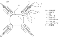
図1は、本実施の形態に係る切断装置100の側面図であり、図2はその平面図である。
被切断対象物を切断する円板形状の切断刃1は、シャフト2により切断刃1の円中心を通され、このシャフト2を回転中心軸として回転可能に支持されている。
本実施の形態では、切断刃1を4個としているが必ずしもこの限りではない。
Embodiments of the present invention will be described below with reference to the drawings.
FIG. 1 is a side view of a
A disc-
In the present embodiment, four
シャフト2の両端部は、切断刃1を挟み込むように切断刃1の上下に配置された板3にそれぞれ接続されていて、この板3はブロック4により固定されている。
この切断刃1、シャフト2、板3、ブロック4で構成される機構部を、切断ユニット5と呼ぶ。
切断ユニット5の基部を構成するブロック4は、台形ネジ6のネジ軸上に設置されている。
Both ends of the shaft 2 are respectively connected to
The mechanism portion composed of the
The block 4 constituting the base of the
台形ネジ6は自在継手を介してサーボモータ7のシャフト8へと連結されており、サーボモータ7の回転が台形ネジ6へ伝達される構造となっている。
サーボモータ7が駆動して台形ネジ6が回転すると、台形ネジ6の回転運動がネジ軸上の直線運動に変換されてネジ軸上に搬送力が生じるので、台形ネジ6のネジ軸上に設置された切断ユニット5はサーボモータ7の回転方向に合わせてネジの先端部から基端部にかけて前進および後退運動をする。
The
When the
こうして、サーボモータ7の回転数と回転方向を制御する事により、切断刃1の台形ネジ6のネジ軸上の位置を制御することが可能な構造となっている。
サーボモータ7には、その回転角度および回転速度を検出するエンコーダが設けられている。
検出された回転角度および回転速度は、制御装置にフィードバックされ、指令値と一致するよう制御される。
こうして4つの切断ユニット5はそれぞれが有するサーボモータ7によって、個々独立して台形ネジ6のネジ軸上の位置を制御される。
Thus, the position of the
The
The detected rotation angle and rotation speed are fed back to the control device and controlled to coincide with the command value.
Thus, the position of the
また、台形ネジ6の両側には、ネジ軸に並行にリニアガイド9が設置されていて、切断ユニット5を支持している。これにより、切断ユニット5の台形ネジ6のネジ軸上でのスムーズな前進後退運動が可能である。
Further,
回転台10は被切断対象物である圧縮機11を載置する台であり、油圧チャック12は圧縮機11を挟み込み固定する為の伸縮可能な保持部である。
圧縮機11はレーストラック状または小判状の形状を有している。
回転台10の回転軸は、対象物用サーボモータ13と連結しており、圧縮機11を任意の回転方向に任意の速度で回転させることが可能である。
The rotary table 10 is a table on which a
The
The rotating shaft of the
以上のように構成された切断装置100の使用手順を図3、図4、図5を用いて説明する。
図3は、切断ユニット5が圧縮機11の外殻形状に合わせて追従している状態を表す図である。
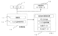
図4は、切断装置100のブロック図である。
図5は、切断装置100を構成する制御装置14の動作フロー図である。
A procedure for using the
FIG. 3 is a diagram illustrating a state in which the
FIG. 4 is a block diagram of the
FIG. 5 is an operation flowchart of the control device 14 constituting the
制御装置14は、切断装置100の動作制御をおこなう制御処理部である。
メモリ15は、圧縮機11の切断工程におけるサーボモータ7と対象物用サーボモータ13のそれぞれの回転角度および回転速度や、その他の切断に必要なデータを格納する記憶装置である。
The control device 14 is a control processing unit that controls the operation of the
The
切断処理を開始するにあたって、被切断対象物である圧縮機11の外殻の肉厚を予め制御装置14に設定しておく必要がある。しかし、圧縮機11の外殻の肉厚はメーカーによる違いも少なくほぼ3mm〜4mm厚であるので、ディフォルト値として3mm又は4mmを一度設定しておけば、この値はメモリ15に保存され切断処理開始時に呼び出される為、切断工程毎に設定する必要は無い。
When starting the cutting process, it is necessary to set the thickness of the outer shell of the
まず、切断ユニット5を台形ネジ6の基端部まで後退させた状態で、圧縮機11を回転台10上に載置し、油圧チャック12で圧縮機11を保持する(ステップ1〜2)。
制御装置14はエンコーダで検出されたサーボモータ7の回転角度から、切断ユニット5の台形ネジ6のネジ軸上の位置(以降、位置データという)を算出する演算部17を備えており、切断ユニット5を台形ネジ6の基端部まで後退させた時の位置データを初期位置としてメモリ15に格納する(ステップ3)。
First, with the
The control device 14 includes a
次に4つの切断ユニット5をそれぞれ台形ネジ6の先端部側に向けて前進させる(ステップ4)。
この時、切断刃1の刃先が圧縮機11に接触した際の負荷で、切断ユニット5の前進が停止するように、サーボモータ7のトルク値は低く自動設定されている。
そして、4枚の切断刃1の刃先が全て圧縮機11に接触して、切断ユニット5の前進が停止した際の切断ユニット5の位置データを取得してメモリ15に格納する(ステップ5、6)。
Next, the four
At this time, the torque value of the
Then, all the cutting edges of the four
こうして切断刃1が圧縮機11に軽圧で接触した状態で、圧縮機11から各切断刃1の刃先が離れず、且つ切断刃1が圧縮機11の形状に十分追従できる5秒/1回転程度の低速で、回転台10を360度回転させる(ステップ7)。
この時、切断刃1が圧縮機11の外殻形状に合わせて刃先を追従するため、切断ユニット5は台形ネジ6のネジ軸上で前進後退運動をおこなう。
図3は、切断ユニット5が圧縮機11の外殻形状に合わせて追従する状態を示す図である。
この時、回転台10が対象物用サーボモータ13によって回転する際の回転中の各角度における切断ユニット5の位置データをメモリ15に記録する。この位置データはエンコーダの回転角で検出可能である(ステップ8)。
これにより、圧縮機11の外殻の形状を、制御装置14の演算部17によりデータ化して、メモリ15に格納することが可能となる(ステップ9)。
Thus, in a state where the
At this time, since the
FIG. 3 is a diagram illustrating a state in which the
At this time, the position data of the
Thereby, the shape of the outer shell of the
また本実施の形態では、圧縮機11の外殻全周を切断刃1にてトレースする工程において、回転台10を360度回転させているが、切断刃1が複数である場合の回転台10の回転角度を、360度÷切断刃1の数(本例では360度÷4個=90度)、としても圧縮機11の外殻形状の全周のトレースは可能であるので問題は無い。
In this embodiment, in the process of tracing the entire outer shell of the
圧縮機11の外殻形状のトレースが終了すると、サーボモータ7のトルク値は、圧縮機11の外殻シェルを切断出来る程度の高い値に自動設定される。これにより、トルク値に比例した切り込み量が設定される。
そして回転台10の回転速度を上げて圧縮機11を回転させ、各回転角度において圧縮機11の外殻形状をトレースした際の切断ユニット5の位置データと一致する位置に切断ユニット5の位置をサーボモータ7で制御し、且つ各切断刃1から常時均等な量の切り込みを圧縮機11に与えて切断する(ステップ10〜12)。
When the outer shell-shaped trace of the
Then, the rotation speed of the
例えば、3mmの外殻の厚さを有する歪な形状の圧縮機において、切断刃1の切り込み予定量を0.5mm/1回転と設定すると、圧縮機11の外殻から0.5mmの切断刃1の切り込み量を維持するようなトルク量で切断ユニット5を圧縮機11の外殻形状に追従させて制御し、外殻シェルを切断する。こうすることで、6〜7周程度の回転台10の回転で、切断を完了することが出来る。
For example, in a distorted compressor having an outer shell thickness of 3 mm, when the planned cutting amount of the
また、制御装置14はトルク量制御手段16を有している。
このトルク量制御手段16は、メモリ15内に記録されている切断時の切り込み量を維持する為に、サーボモータ7に流れる切断中の電流の増減を検知することでサーボモータ7の負荷値を検知する手段と、それに対応してトルク量の増減を制御する手段とを備えた処理部である。
例えば0.5mm/1回転の切り込み予定量をもって切断している場合において、圧縮機11の外殻が予定より強固である等の理由によって、この切り込み量が切断中に維持出来ていない場合には、0.5mmの切り込み量が得られるまでトルク量を増加させるものである(ステップ13)。
In addition, the control device 14 has torque amount control means 16.
This torque amount control means 16 detects the increase / decrease of the current during cutting flowing in the
For example, in the case of cutting with a planned cutting amount of 0.5 mm / 1 rotation, when the cutting amount cannot be maintained during cutting because the outer shell of the
また、メモリ15内には切断時における切断刃1への負荷を考慮した、トルク量制限値が予め記録されている。
トルク量制御手段16は、このトルク量制限値を超えることがないように、動作中のサーボモータ7の負荷を監視する。
例えば、0.5mm/1回転の切り込み予定量を持って切断中に、大きな負荷が刃物Bにかかり、サーボモータ7のトルク値がトルク量制限値を超えた場合には、予め設定された切り込み量が大きく適切で無いと判断し、切り込み量の設定を例えば0.3mm/1回転となるようにトルク量を自動で減少させて調節するものである(ステップ14)。
このように負荷値をモニターして切り込み量の制御が可能なので、切断刃1への負荷を低減して刃物寿命の低下を防ぐことが可能である。
In the
The torque amount control means 16 monitors the load on the
For example, if a large load is applied to the blade B during cutting with a scheduled cutting amount of 0.5 mm / 1 rotation, and the torque value of the
In this way, since the load value can be monitored and the cutting amount can be controlled, it is possible to reduce the load on the
また、トルク量制御手段16が切り込み量を減少させた場合においても、サーボモータ7のトルク量がトルク量制限値を尚も超える場合には、回転台10の回転速度を低速化させる(ステップ14)。
このように、切り込み量を減少させ、且つ回転台10の回転を低速化した場合でも、サーボモータ7のトルク量がトルク量制限値を超える場合には、異常状態であると判断し、切断工程を停止する(ステップ15、17、18)。
またステップ14の工程にて、切り込み量を減少させ且つ回転台10の回転を低速化させて、所定の時間経過後にサーボモータ7のトルク量がトルク量制限値以下となった場合には、通常切断処理を続行する(ステップ16)。
Even when the torque amount control means 16 reduces the cutting amount, if the torque amount of the
As described above, even when the cutting amount is reduced and the rotation speed of the
In step 14, when the amount of cutting is reduced and the rotation of the
一方、ステップ13の工程において検出された負荷に対応するトルク量が制限値以下である場合には、切り込み量の調節や回転台10の回転速度の処理は行わず、通常の切断処理を続行する(ステップ19〜21)。
On the other hand, when the torque amount corresponding to the load detected in the
設定された肉厚値分だけ切断ユニット5が台形ネジ6のネジ軸を移動し、切断刃1にかかる負荷が無くなったのを検知すると、切断完了と判断して、切断ユニット5を初期位置まで後退させて、回転台10の回転を停止し切断処理を終了する(ステップ22〜25)。
When the
こうして、被切断対象物が歪な形状を有していても、圧縮機に押圧する切断力の制御をサーボモータで行うために、被切断対象物の外殻形状に合わせて切断刃1を高速で移動させることが出来るので、回転台10を高速回転させても切断刃1が被切断対象物の外殻形状に十分追従でき、切断に要する時間を短縮することが出来る。
Thus, even if the object to be cut has a distorted shape, in order to control the cutting force pressed against the compressor by the servo motor, the
また、切断前に被切断対象物の外殻形状をトレースして、外殻形状をデータ化して記録しておくので、この記録した外殻形状のデータに基づいて切断時に素早く切断刃1を移動させることが出来る。
また、圧縮機のように形状に規格が無く、三角や四角など無数の種類の形状が存在する被切断対象物において、被切断対象物の幅や直径等の諸処のパラメータを、被切断対象物の形状が変わる度に手動で入力する必要がなく自動化されているため、切断工程にかかる時間を大幅に短縮出来る。
In addition, the outer shell shape of the object to be cut is traced before cutting, and the outer shell shape is recorded and recorded. Therefore, the
In addition, the parameters of various parts such as the width and diameter of the object to be cut can be set in the object to be cut which has no standard shape such as a compressor and there are countless kinds of shapes such as triangles and squares. Since there is no need to input manually every time the shape of the plate changes, the time required for the cutting process can be greatly reduced.
また、レシプロ圧縮機の外殻の切断装置などで従来から多く使用される、非接触式センサーなどでは、圧縮機の外殻と切断物との距離を検知する際の検知ミスが発生していたが、本実施の形態では、実際に切断を行う切断ユニット5にて被切断対象物の外殻形状の検知を行うため、切断時の誤差の発生が抑えられ、確実に所望の切り込み量を圧縮機11に与える事が出来る。
In addition, non-contact sensors, which have been used in many cases in the reciprocating compressor outer shell cutting device, have caused a detection error when detecting the distance between the compressor outer shell and the cut object. However, in the present embodiment, since the outer shell shape of the object to be cut is detected by the
従来の切断刃を2枚一組とした門型構造の切断機構では切断刃の稼働範囲が規制されるため、被切断物の外殻全周に渡って均一な切断力がかけられず、切断刃の切り込み量が不均一となり、本来切断が完了すべき時点においても、殆ど切り込みが入っていない「未切断箇所」が生じることがあり、この残った未切断箇所を切断する為に時間を要していた。
しかし、本実施の形態にかかる切断刃1の切断機構は、切断刃毎に独立して切り込み量の制御が可能であるので、個々の切断刃1の稼働範囲が規制されることが無く、被切断対象物の全周に渡り均一な切り込み量を与えることができ、大きな未切断箇所が生ずることが無いため、従来に比べて切断に要する時間を短縮出来る。
In the conventional gate-type structure with two cutting blades as a set, the operating range of the cutting blade is restricted, so a uniform cutting force cannot be applied over the entire outer shell of the object to be cut. Even when the cutting should be completed, there may be an “uncut portion” that has almost no cut, and it takes time to cut the remaining uncut portion. It was.
However, since the cutting mechanism of the
また従来では、未切断箇所が切断の後半課程にて大きく残った場合に、この未切断箇所に切断刃が大きく乗り上げることがあり、切断刃の刃先へ大きな衝撃がかかり、刃物寿命の低下が懸念されていた。
本実施の形態では、未切断箇所が切断課程後半で大きく残る事が無いために、このような切断刃への衝撃を低減することが出来る。
また、被切断対象物の外殻の肉厚、切断刃1の切り込み量および回転台10の回転速度を比較することにより、切断に要する時間の予測が可能になることから、リサイクル工程における工程設計が容易となる。
Also, in the past, when a large portion of the uncut portion remains in the latter half of the cutting process, the cutting blade may ride over the uncut portion, and a large impact is applied to the cutting edge of the cutting blade, which may reduce the tool life. It had been.
In this embodiment, since the uncut portion does not remain largely in the latter half of the cutting process, it is possible to reduce such an impact on the cutting blade.
In addition, it is possible to predict the time required for cutting by comparing the thickness of the outer shell of the object to be cut, the amount of cutting of the
なお以上で述べた実施の形態は本発明の好適な具体例であるから、技術的に好ましい種々の限定が付されているが、本発明の範囲は以上の説明において特に本発明を限定する旨の記載がない限りこれらの形態に限られるものではない。
また切断刃1の数が多い程、切断工程に要する時間を短縮出来ることは言うまでもない。
Since the embodiments described above are preferred specific examples of the present invention, various technically preferable limitations are attached, but the scope of the present invention is particularly limited in the above description. Unless otherwise described, the present invention is not limited to these forms.
Needless to say, the larger the number of
このように、サーボモータで切断刃の位置制御が行うことで、歪な形状を有する被切断対象物であっても、圧縮機を高速回転させて短時間で切断を完了することの出来る圧縮機の切断装置と切断方法を提供することが出来る。 Thus, by controlling the position of the cutting blade with a servo motor, a compressor that can complete cutting in a short time by rotating the compressor at a high speed even for an object to be cut having a distorted shape. A cutting device and a cutting method can be provided.
1 切断刃、2 シャフト、3 板、4 ブロック、5 切断ユニット、
6 台形ネジ、7 サーボモータ、8 シャフト、9 リニアガイド、10 回転台、
11 圧縮機、12 油圧チャック、13 対象物用サーボモータ、14 制御装置、
15 メモリ、16 トルク量制御手段、17 演算部、100 切断装置。
1 cutting blade, 2 shafts, 3 plates, 4 blocks, 5 cutting units,
6 trapezoidal screws, 7 servo motors, 8 shafts, 9 linear guides, 10 turntables,
11 Compressor, 12 Hydraulic chuck, 13 Servo motor for object, 14 Control device,
15 memory, 16 torque amount control means, 17 calculation unit, 100 cutting device.
Claims (1)
前記圧縮機に前記切断刃を接触させつつ前記圧縮機を回転させ、各回転角度における前記切断刃の位置を記憶するステップと、Rotating the compressor while bringing the cutting blade into contact with the compressor, and storing the position of the cutting blade at each rotation angle;
前記圧縮機を回転させ、各回転角度において前記記憶された位置から前記切断刃を切り込ませて前記圧縮機を切断するステップとを備えた圧縮機の切断方法。And a step of cutting the compressor by rotating the compressor and cutting the cutting blade from the stored position at each rotation angle.
Priority Applications (1)
| Application Number | Priority Date | Filing Date | Title |
|---|---|---|---|
| JP2011132773A JP5602683B2 (en) | 2011-06-15 | 2011-06-15 | Compressor cutting method |
Applications Claiming Priority (1)
| Application Number | Priority Date | Filing Date | Title |
|---|---|---|---|
| JP2011132773A JP5602683B2 (en) | 2011-06-15 | 2011-06-15 | Compressor cutting method |
Publications (3)
| Publication Number | Publication Date |
|---|---|
| JP2013000821A JP2013000821A (en) | 2013-01-07 |
| JP2013000821A5 JP2013000821A5 (en) | 2013-11-21 |
| JP5602683B2 true JP5602683B2 (en) | 2014-10-08 |
Family
ID=47669947
Family Applications (1)
| Application Number | Title | Priority Date | Filing Date |
|---|---|---|---|
| JP2011132773A Expired - Fee Related JP5602683B2 (en) | 2011-06-15 | 2011-06-15 | Compressor cutting method |
Country Status (1)
| Country | Link |
|---|---|
| JP (1) | JP5602683B2 (en) |
Families Citing this family (6)
| Publication number | Priority date | Publication date | Assignee | Title |
|---|---|---|---|---|
| KR101323643B1 (en) * | 2013-05-06 | 2013-11-05 | 주식회사 우리산업 | Cutting machine for refrigeration compressor |
| CN103706883B (en) * | 2013-12-17 | 2015-10-21 | 新昌县澄潭镇康成机械配件厂 | A kind of Manual type shell disintegration device of little compressor |
| KR200478631Y1 (en) | 2015-07-16 | 2015-10-29 | 방의석 | Compressors for refrigeration using a rotary knife cutting machine |
| KR101832061B1 (en) | 2016-07-13 | 2018-02-23 | 김명호 | A dismantle machine for trash air compressor motor and use methods of the machine for use |
| KR101881836B1 (en) * | 2017-07-24 | 2018-07-26 | 이상태 | Automatic cutting device for refrigerator waste compressor housing |
| CN110624942B (en) * | 2019-10-28 | 2020-07-10 | 常州市第一人民医院 | Dry powder jar centralized processing breaks and tears flowing back sorter open |
Family Cites Families (4)
| Publication number | Priority date | Publication date | Assignee | Title |
|---|---|---|---|---|
| JP3422576B2 (en) * | 1994-11-10 | 2003-06-30 | 三菱重工業株式会社 | How to cut steel pipe |
| FI20045377A (en) * | 2004-10-08 | 2006-04-20 | Plantool Oy | Method and apparatus for cutting a thick-walled pipe |
| JP2008105142A (en) * | 2006-10-26 | 2008-05-08 | Eishin Giken:Kk | Cutting device |
| JP5349926B2 (en) * | 2008-12-01 | 2013-11-20 | 昭和電工株式会社 | Pipe cutting method and photosensitive drum substrate manufacturing method |
-
2011
- 2011-06-15 JP JP2011132773A patent/JP5602683B2/en not_active Expired - Fee Related
Also Published As
| Publication number | Publication date |
|---|---|
| JP2013000821A (en) | 2013-01-07 |
Similar Documents
| Publication | Publication Date | Title |
|---|---|---|
| JP5602683B2 (en) | Compressor cutting method | |
| JP4261563B2 (en) | Machining origin setting method and machine tool for implementing the method | |
| CN102248435B (en) | Automatic turn-over device for workpieces | |
| TW201632294A (en) | Intelligent control system of machine tool and control method thereof | |
| JP2009262289A (en) | Cutting device | |
| US20120325061A1 (en) | Machining device | |
| CN114728429A (en) | Cutting machine for products made of cellulosic material and relative method | |
| JP5534189B2 (en) | Machining robot and its machining control method | |
| JP2009196022A (en) | Grinding method and grinding device | |
| JP2007175827A (en) | Drilling device for resin part, drilling robot system for resin part and drilling method for resin part | |
| JP4534847B2 (en) | Cutting method and cutting apparatus | |
| CN207616102U (en) | A kind of bipolar plate edge cutting machine | |
| CN207858930U (en) | A kind of automatic gas cutting machine | |
| JP4692046B2 (en) | Control method and apparatus for tailstock | |
| JP2014067220A (en) | Numerical control apparatus and rotation table position adjustment method | |
| JP6549641B2 (en) | Machine tool and waiting time changing method | |
| TWI392570B (en) | Verfahren und vorrichtung zum optimieren von querbearbei-tungsvorgaengen | |
| JP2012148352A (en) | Phase adjustment device and method for gear grinding machine | |
| JP6904941B2 (en) | Control device and control method | |
| JP2508051B2 (en) | Processing device with correction function | |
| JP4387752B2 (en) | Raw wood cutting method and apparatus | |
| JP4685560B2 (en) | Rotary blade polishing equipment | |
| JP2563025B2 (en) | Cutting control method for parts | |
| KR101498303B1 (en) | Appratus and Method for Controlling Rigid Tapping Retract | |
| JP2686510B2 (en) | Whetstone repair device for double-headed grinder |
Legal Events
| Date | Code | Title | Description |
|---|---|---|---|
| A521 | Request for written amendment filed |
Free format text: JAPANESE INTERMEDIATE CODE: A523 Effective date: 20131004 |
|
| A621 | Written request for application examination |
Free format text: JAPANESE INTERMEDIATE CODE: A621 Effective date: 20131004 |
|
| A131 | Notification of reasons for refusal |
Free format text: JAPANESE INTERMEDIATE CODE: A131 Effective date: 20140624 |
|
| A977 | Report on retrieval |
Free format text: JAPANESE INTERMEDIATE CODE: A971007 Effective date: 20140625 |
|
| A521 | Request for written amendment filed |
Free format text: JAPANESE INTERMEDIATE CODE: A523 Effective date: 20140703 |
|
| TRDD | Decision of grant or rejection written | ||
| A01 | Written decision to grant a patent or to grant a registration (utility model) |
Free format text: JAPANESE INTERMEDIATE CODE: A01 Effective date: 20140723 |
|
| A61 | First payment of annual fees (during grant procedure) |
Free format text: JAPANESE INTERMEDIATE CODE: A61 Effective date: 20140820 |
|
| R150 | Certificate of patent or registration of utility model |
Ref document number: 5602683 Country of ref document: JP Free format text: JAPANESE INTERMEDIATE CODE: R150 |
|
| R250 | Receipt of annual fees |
Free format text: JAPANESE INTERMEDIATE CODE: R250 |
|
| R250 | Receipt of annual fees |
Free format text: JAPANESE INTERMEDIATE CODE: R250 |
|
| R250 | Receipt of annual fees |
Free format text: JAPANESE INTERMEDIATE CODE: R250 |
|
| R250 | Receipt of annual fees |
Free format text: JAPANESE INTERMEDIATE CODE: R250 |
|
| R250 | Receipt of annual fees |
Free format text: JAPANESE INTERMEDIATE CODE: R250 |
|
| R250 | Receipt of annual fees |
Free format text: JAPANESE INTERMEDIATE CODE: R250 |
|
| LAPS | Cancellation because of no payment of annual fees |