JP5602673B2 - Fluid control valve - Google Patents
Fluid control valve Download PDFInfo
- Publication number
- JP5602673B2 JP5602673B2 JP2011098743A JP2011098743A JP5602673B2 JP 5602673 B2 JP5602673 B2 JP 5602673B2 JP 2011098743 A JP2011098743 A JP 2011098743A JP 2011098743 A JP2011098743 A JP 2011098743A JP 5602673 B2 JP5602673 B2 JP 5602673B2
- Authority
- JP
- Japan
- Prior art keywords
- piston
- fluid control
- control valve
- knob
- cam
- Prior art date
- Legal status (The legal status is an assumption and is not a legal conclusion. Google has not performed a legal analysis and makes no representation as to the accuracy of the status listed.)
- Active
Links
Images


Classifications
-
- F—MECHANICAL ENGINEERING; LIGHTING; HEATING; WEAPONS; BLASTING
- F16—ENGINEERING ELEMENTS AND UNITS; GENERAL MEASURES FOR PRODUCING AND MAINTAINING EFFECTIVE FUNCTIONING OF MACHINES OR INSTALLATIONS; THERMAL INSULATION IN GENERAL
- F16K—VALVES; TAPS; COCKS; ACTUATING-FLOATS; DEVICES FOR VENTING OR AERATING
- F16K31/00—Actuating devices; Operating means; Releasing devices
- F16K31/44—Mechanical actuating means
- F16K31/52—Mechanical actuating means with crank, eccentric, or cam
- F16K31/524—Mechanical actuating means with crank, eccentric, or cam with a cam
- F16K31/52491—Mechanical actuating means with crank, eccentric, or cam with a cam comprising a diaphragm cut-off apparatus
-
- F—MECHANICAL ENGINEERING; LIGHTING; HEATING; WEAPONS; BLASTING
- F16—ENGINEERING ELEMENTS AND UNITS; GENERAL MEASURES FOR PRODUCING AND MAINTAINING EFFECTIVE FUNCTIONING OF MACHINES OR INSTALLATIONS; THERMAL INSULATION IN GENERAL
- F16K—VALVES; TAPS; COCKS; ACTUATING-FLOATS; DEVICES FOR VENTING OR AERATING
- F16K7/00—Diaphragm valves or cut-off apparatus, e.g. with a member deformed, but not moved bodily, to close the passage ; Pinch valves
- F16K7/12—Diaphragm valves or cut-off apparatus, e.g. with a member deformed, but not moved bodily, to close the passage ; Pinch valves with flat, dished, or bowl-shaped diaphragm
- F16K7/14—Diaphragm valves or cut-off apparatus, e.g. with a member deformed, but not moved bodily, to close the passage ; Pinch valves with flat, dished, or bowl-shaped diaphragm arranged to be deformed against a flat seat
- F16K7/16—Diaphragm valves or cut-off apparatus, e.g. with a member deformed, but not moved bodily, to close the passage ; Pinch valves with flat, dished, or bowl-shaped diaphragm arranged to be deformed against a flat seat the diaphragm being mechanically actuated, e.g. by screw-spindle or cam
Description
本発明は、第1ポートと第2ポートとを連通する流体の流路に形成された弁座と、前記弁座に当接又は離間して流体の流れを制御する弁体と、前記弁体と連結するピストンと、前記ピストンを前記弁体の開閉方向に移動させるノブとを有する流体制御弁に関する。 The present invention provides a valve seat formed in a fluid flow path that communicates between a first port and a second port, a valve body that contacts or separates from the valve seat and controls the flow of fluid, and the valve body And a knob for moving the piston in the opening and closing direction of the valve body.
従来、この種の技術として、下記の特許文献1に記載される流体制御弁300がある。図22に、特許文献1に記載される流体制御弁300の断面図を示す。図22に示すように、流体制御弁300は、弁座301に当接又は離間する弁体302を有する主軸303を備え、スプリング304が主軸303を下(弁閉)方向に付勢している。主軸303がスプリング304により付勢されることで弁体302を弁座301に押圧シールしている。
また、流体制御弁300には、ハンドル305が形成され、ハンドル305内にはカム部材306が固定されている。流体制御弁300を開弁する際には、ハンドル305を回動し主軸303をカム部材306により上昇させ、弁体302を弁座301から離間させる。具体的には、カム部材306内には2つの鋼球307が備えられ、2つの鋼球307はハンドル305が回動することによりその間隔が狭くなる。また、主軸303の外周であって、2つの鋼球307と当接する部分には上側から下側に向かって狭いテーパ部が成形されている。そのため、ハンドル305を回動させることにより、2つの鋼球307の間隔が狭まり、テーパ部を持ちあげる形となり主軸303を上昇させている。
Conventionally, as this type of technology, there is a
In addition, a
特許文献2及び3には、本出願人が行ったカム部材を使用しない流体制御弁に関するものである。カム部材を使用しないものであるため、詳細な説明を割愛する。
しかしながら、従来技術には、以下の問題があった。
すなわち、スプリング304は、弁体302を弁座301に押圧シールするためのものであり高荷重(高反発力)のスプリングとなる。そのため、第1に、スプリング304が高荷重のものであるため、ハンドル305を回動させ2つの鋼球307の間隔を狭め主軸303を持ちあげるのに、非常に強いトルクを加える必要があるため問題となる。ハンドルと主軸の螺合している部分を増やし、ハンドルを多く回すことにより強いトルクを加えることができるが、流体制御弁が大型化するため、また問題となる。そのため、市場にあるものはスプリングで流体制御弁を開弁し、手動で閉弁(人間の力で閉弁)するタイプがほとんどである。
さらに、ハンドルを多く回すことにより閉弁又は開弁した場合、ハンドルの位置が定まらない。そのため、ハンドルの位置を確認することにより一見して流体制御弁の開閉状態を確認することが困難な場合がある。
However, the prior art has the following problems.
That is, the
Furthermore, when the valve is closed or opened by turning the handle many times, the position of the handle is not fixed. Therefore, it may be difficult to confirm the open / close state of the fluid control valve at a glance by confirming the position of the handle.
また、第2に、主軸303を2つの鋼球307が間隔を狭めて持ちあげるため、主軸303の強度も上げる必要がある。しかし、流体制御弁は樹脂製であるため強度を上げるためには流体制御弁を大型化してしまうという問題がある。また、樹脂製の流体制御弁はもともと金属に比べ強度が弱いために使用状況によっては破損しやすいという問題もある。
Secondly, since the two
そこで、本発明は、上記問題点を解決するためになされたものであり、その目的は流体制御弁を開閉する際に必要なトルクを軽減できる流体制御弁の提供することを目的とする。 Therefore, the present invention has been made to solve the above-described problems, and an object of the present invention is to provide a fluid control valve that can reduce the torque required for opening and closing the fluid control valve.
上記目的を達成するために、本発明の一態様における流体制御弁は、以下の構成を有する。
(1)第1ポートと第2ポートが形成され、前記第1ポートと前記第2ポートとを連通する流体の流路に弁座を形成されたボディ部と、前記ボディ部に連結されるシリンダと、シリンダ内に弁座方向と反弁座方向に摺動可能な状態で配置されるピストンと、前記ピストンに連結され、前記弁座に当接又は離間して流体の流れを制御する弁体と、前記シリンダに連結されるカバーと、前記カバーを貫通して前記カバーに回動可能な状態で配置されるノブ連結部材と、前記ノブ連結部材が前記カバーの外部に突出する部分に連結されて、前記ノブ連結部材と連動して回転することにより、前記ピストンを前記弁体の開閉方向に移動させるノブとを有する流体制御弁において、前記ノブ連結部材と前記ピストンの間に、前記ノブ連結部材と前記ピストンとを連結するカム部材が介在していること、前記カム部材は、シリンダ内に弁座方向及び反弁座方向に移動可能に配置されると共に、前記ノブ連結部材と一体的に回動可能に配置されていること、前記カム部材のノブ連結部材側の端面に対して当接した状態で配置されて前記カム部材を弁座方向に付勢する第1付勢部材を有すること、前記ピストンを反弁座方向に付勢する第2付勢部材を有すること、前記シリンダ内の、弁が全開状態の場合に前記カム部材に当接する位置に形成され、前記カム部材の弁座方向への移動を制限する内筒段部を有すること、(1)前記カム部材の前記ピストンと当接する当接端面に、凹形状のカム面が形成されていること、及び、前記ピストンの前記カム面と当接する部分には凸形状のピストン係合部が形成されていること、又は、(2)前記カム部材の前記ピストンと当接する当接端面に、凸形状のカム面が形成されていること、及び、前記ピストンの前記カム面と当接する部分には凹形状のピストン係合部が形成されていること、のいずれか一つの組み合わせを有すること、前記カム部材は、弁が全開状態である場合には、前記第1付勢部材に付勢されて前記内筒段部に当接し、前記第1付勢部材の荷重を前記ピストンに伝達せず、弁が全閉状態である場合には、前記内筒段部から離間して前記第1付勢部材に押圧され、前記ピストンを弁座方向へと押圧し、前記第1付勢部材の荷重により前記弁体を前記弁座に押圧すること、を特徴とする。
In order to achieve the above object, a fluid control valve according to an aspect of the present invention has the following configuration.
(1) first and second ports are formed, wherein a body portion formed with a valve seat in a flow path of the fluid between the first port communicating with said second port, a cylinder connected to said body portion A piston that is slidable in the valve seat direction and the counter valve seat direction in the cylinder, and a valve body that is connected to the piston and controls the flow of fluid by contacting or separating from the valve seat A cover coupled to the cylinder, a knob coupling member disposed in a rotatable manner through the cover, and the knob coupling member coupled to a portion protruding from the cover. Te, wherein by rotating in conjunction with the knob coupling member, the fluid control valve and a knob for moving the piston in the closing direction of the valve body, between the said knob coupling member piston, the knob Connecting member and the pipe The cam member for connecting the emission is interposed, the cam member, while being movably disposed in the valve seat direction and Hanben seat direction in the cylinder, the knob coupling member integrally rotatably A first urging member disposed in contact with an end face of the cam member on the knob connecting member side and urging the cam member in a valve seat direction, the piston A second urging member that urges the cam member in the valve seat direction, and is formed at a position in the cylinder that contacts the cam member when the valve is fully open. having a cylindrical stepped portion in limiting the movement, (1) to the piston and abutting abutment end face of the cam member, the concave cam surface is formed, and said cam surface of said piston and A convex piston engaging part is formed at the abutting part. Or (2) a convex cam surface is formed on the contact end surface of the cam member that contacts the piston, and a portion of the piston that contacts the cam surface. The cam member is biased by the first biasing member when the valve is fully open, having a combination of any one of a concave piston engaging portion and a valve. The first urging member is separated from the inner tube step portion when it contacts the inner tube step portion, does not transmit the load of the first urging member to the piston, and the valve is in a fully closed state. Pressed by a member, pressing the piston toward the valve seat, and pressing the valve body against the valve seat by a load of the first urging member .
(2)(1)に記載する流体制御弁において、前記カム部材に前記カム面が2か所以上形成されていること、が好ましい。
(3)(1)又は(2)に記載する流体制御弁において、前記カム面は2以上の傾斜角度を有するテーパ面を有すること、が好ましい。
(2) In the fluid control valve described in (1), it is preferable that two or more cam surfaces are formed on the cam member.
(3) In the fluid control valve described in (1) or (2), it is preferable that the cam surface has a tapered surface having an inclination angle of 2 or more.
(4)(1)乃至(3)に記載するいずれか一つの流体制御弁において、前記流体制御弁は、前記ノブと前記カム部材が約90度回動することにより、前記弁座に前記弁体が当接又は離間すること、が好ましい。
(5)(1)乃至(4)に記載するいずれか一つの流体制御弁において、前記カム部材の前記当接端面に前記ピストンが閉方向にスライドした際に前記ピストン係合部と係合する当接端面係合部が形成されていること、が好ましい。
(4) In any one of the fluid control valves described in (1) to (3), the fluid control valve is configured so that the valve and the cam member are rotated about 90 degrees, and the valve seat is moved to the valve seat. It is preferred that the body abuts or separates.
(5) In any one of the fluid control valves according to (1) to (4), the piston engages with the piston engaging portion when the piston slides in the closing direction on the contact end surface of the cam member. It is preferable that an abutting end surface engaging portion is formed.
(6)(1)乃至(5)に記載するいずれか一つの流体制御弁において、前記ボディ部と前記シリンダと前記カバーにより弁本体を形成し、前記ノブは、前記カム部材が内蔵される前記弁本体の外形寸法よりも小さいこと、が好ましい。
(7)(1)乃至(6)に記載するいずれか一つの流体制御弁において、前記ピストンの移動を前記ノブによる駆動に代えて、モータ駆動又はシリンダ駆動を用いること、が好ましい。
(6) In any one of the fluid control valves according to (1) to (5), a valve main body is formed by the body portion, the cylinder, and the cover, and the knob includes the cam member. It is preferably smaller than the outer dimension of the valve body.
(7) In any one of the fluid control valves described in (1) to (6), it is preferable to use motor drive or cylinder drive instead of the movement of the piston by the knob.
上記流体制御弁の作用及び効果について説明する。
(1)第1ポートと第2ポートが形成され、前記第1ポートと前記第2ポートとを連通する流体の流路に弁座を形成されたボディ部と、前記ボディ部に連結されるシリンダと、シリンダ内に弁座方向と反弁座方向に摺動可能な状態で配置されるピストンと、前記ピストンに連結され、前記弁座に当接又は離間して流体の流れを制御する弁体と、前記シリンダに連結されるカバーと、前記カバーを貫通して前記カバーに回動可能な状態で配置されるノブ連結部材と、前記ノブ連結部材が前記カバーの外部に突出する部分に連結されて、前記ノブ連結部材と連動して回転することにより、前記ピストンを前記弁体の開閉方向に移動させるノブとを有する流体制御弁において、前記ノブ連結部材と前記ピストンの間に、前記ノブ連結部材と前記ピストンとを連結するカム部材が介在していること、前記カム部材は、シリンダ内に弁座方向及び反弁座方向に移動可能に配置されると共に、前記ノブ連結部材と一体的に回動可能に配置されていること、前記カム部材のノブ連結部材側の端面に対して当接した状態で配置されて前記カム部材を弁座方向に付勢する第1付勢部材を有すること、前記ピストンを反弁座方向に付勢する第2付勢部材を有すること、前記シリンダ内の、弁が全開状態の場合に前記カム部材に当接する位置に形成され、前記カム部材の弁座方向への移動を制限する内筒段部を有すること、(1)前記カム部材の前記ピストンと当接する当接端面に、凹形状のカム面が形成されていること、及び、前記ピストンの前記カム面と当接する部分には凸形状のピストン係合部が形成されていること、又は、(2)前記カム部材の前記ピストンと当接する当接端面に、凸形状のカム面が形成されていること、及び、前記ピストンの前記カム面と当接する部分には凹形状のピストン係合部が形成されていること、のいずれか一つの組み合わせを有すること、前記カム部材は、弁が全開状態である場合には、前記第1付勢部材に付勢されて前記内筒段部に当接し、前記第1付勢部材の荷重を前記ピストンに伝達せず、弁が全閉状態である場合には、前記内筒段部から離間して前記第1付勢部材に押圧され、前記ピストンを弁座方向へと押圧し、前記第1付勢部材の荷重により前記弁体を前記弁座に押圧することにより、高荷重の第1付勢部材に対してカム部材を回動させる小さなトルクで圧縮することができ、小さなトルクで閉弁することができる。すなわち、カム部材の凹凸形状のカム面を利用しカム部材を回動させるトルクにより、ピストンに弁体が弁座に当接移動するための直線的な動きを与えることができる。
The operation and effect of the fluid control valve will be described.
(1) first and second ports are formed, wherein a body portion formed with a valve seat in a flow path of the fluid between the first port communicating with said second port, a cylinder connected to said body portion A piston that is slidable in the valve seat direction and the counter valve seat direction in the cylinder, and a valve body that is connected to the piston and controls the flow of fluid by contacting or separating from the valve seat A cover coupled to the cylinder, a knob coupling member disposed in a rotatable manner through the cover, and the knob coupling member coupled to a portion protruding from the cover. Te, wherein by rotating in conjunction with the knob coupling member, the fluid control valve and a knob for moving the piston in the closing direction of the valve body, between the said knob coupling member piston, the knob Connecting member and the pipe The cam member for connecting the emission is interposed, the cam member, while being movably disposed in the valve seat direction and Hanben seat direction in the cylinder, the knob coupling member integrally rotatably A first urging member disposed in contact with an end face of the cam member on the knob connecting member side and urging the cam member in a valve seat direction, the piston A second urging member that urges the cam member in the valve seat direction, and is formed at a position in the cylinder that contacts the cam member when the valve is fully open. having a cylindrical stepped portion in limiting the movement, (1) to the piston and abutting abutment end face of the cam member, the concave cam surface is formed, and said cam surface of said piston and A convex piston engaging part is formed at the abutting part. Or (2) a convex cam surface is formed on the contact end surface of the cam member that contacts the piston, and a portion of the piston that contacts the cam surface. The cam member is biased by the first biasing member when the valve is fully open, having a combination of any one of a concave piston engaging portion and a valve. The first urging member is separated from the inner tube step portion when it contacts the inner tube step portion, does not transmit the load of the first urging member to the piston, and the valve is in a fully closed state. The cam is pressed against the high-load first biasing member by being pressed by the member, pressing the piston in the valve seat direction, and pressing the valve body against the valve seat by the load of the first biasing member. Can be compressed with a small torque that rotates the member, and closed with a small torque. Can be said. That is, it is possible to give the piston a linear movement for the valve body to contact and move to the valve seat by the torque that rotates the cam member using the concave and convex cam surface of the cam member.
また、カム面及びピストン係合部を使用し流体制御弁の開閉を行うことができるため、従来技術のように鋼球を使用する場合と比較して流体制御弁の強度を上げる必要がない。そのため、流体制御弁の素材を全て樹脂とすることができるため、流体制御弁の大型化を防止することができる。
また、作業者がノブとカム部材を少ない回動動作をするだけの簡単な一つの動作で流体制御弁を開閉することができるため、作業者は流体制御弁の開閉を容易にすることができる。
また、少ない回動動作をするだけの簡単な一つの動作で流体制御弁を開閉させることができるため、作動に必要なトルクを軽減することができる。
Further, since the fluid control valve can be opened and closed using the cam surface and the piston engaging portion, it is not necessary to increase the strength of the fluid control valve as compared with the case of using a steel ball as in the prior art. Therefore, since all the materials of the fluid control valve can be made of resin, an increase in the size of the fluid control valve can be prevented.
In addition, the operator can easily open and close the fluid control valve because the fluid control valve can be opened and closed by a single simple operation that allows the operator to rotate the knob and the cam member with less rotation. .
In addition, since the fluid control valve can be opened and closed by a simple operation that requires only a small amount of rotation, the torque required for the operation can be reduced.
(2)(1)に記載する作用及び効果の他、カム部材にカム面が2か所以上形成されていることにより、カム部材の傾きを抑制できる。また、2か所以上カム面を形成することにより、カム面に掛かる1か所当たりの負荷を軽減できるため作業者が容易に流体制御弁の開閉を行うことができる。すなわち、ピストンと当接するカム面に2か所以上形成されていることにより、カム部材が安定するためカム部材の傾きを抑制することができる。カム部材が安定することにより、弁体を均等のトルクで弁座に対して押圧することができる。そのため、弁体に対してシール力を均一に与えることができ、確実にシールすることができる。
また、カム面に掛かる1か所当たりの負荷を軽減できるため、カムの耐久性を向上させることができ、カムを有する流体制御弁の耐久性を向上させることができる。
(2) In addition to the functions and effects described in (1), the cam member is formed with two or more cam surfaces, whereby the inclination of the cam member can be suppressed. In addition, by forming two or more cam surfaces, the load per site on the cam surface can be reduced, so that the operator can easily open and close the fluid control valve. That is, since the cam member is stabilized by being formed at two or more locations on the cam surface in contact with the piston, the inclination of the cam member can be suppressed. When the cam member is stabilized, the valve body can be pressed against the valve seat with an equal torque. Therefore, the sealing force can be uniformly applied to the valve body, and the sealing can be performed reliably.
Further, since the load per place on the cam surface can be reduced, the durability of the cam can be improved, and the durability of the fluid control valve having the cam can be improved.
(3)(1)又は(2)に記載する作用及び効果の他、カム面は2以上の傾斜角度を有するテーパ面を有することにより、ノブに掛かるトルクを傾斜角度により変更することができる。トルクが掛からないノブの前半回動時において傾斜角度を急な角度とすることで、ノブに掛かるトルクは結果として小さくなる。また、トルクが掛かるノブの後半回転時の傾斜角度を緩やかな角度とすることで、ノブに掛かるトルクを小さくすることができる。よって、ノブを回転させるトルクを全体を通して小さくすることができる。 (3) In addition to the functions and effects described in (1) or (2), the cam surface has a tapered surface having an inclination angle of 2 or more, whereby the torque applied to the knob can be changed by the inclination angle. By making the inclination angle steep during the first half rotation of the knob where no torque is applied, the torque applied to the knob is reduced as a result. Moreover, the torque applied to the knob can be reduced by setting the inclination angle during the second half rotation of the knob to which the torque is applied to a gentle angle. Therefore, the torque for rotating the knob can be reduced throughout.
(4)(1)乃至(3)に記載する作用効果の他、流体制御弁は、ノブとカム部材が約90度回動することにより、弁座に弁体が当接又は離間することができる。
約90度回動させるだけの簡単な一つの動作で流体制御弁を開閉させることができるため、作動に必要なトルクを軽減することができる。
また、約90度回動させることにより流体制御弁を開閉することができるので、ノブの向きを外観から見るだけで開状態か閉状態かを一見して認識することができる。一見して開閉状態を確認できるので、作業者の確認作業が容易になり、確認するためのコストを低減することができる。
(5)(1)乃至(4)に記載する作用効果の他、カム部材の当接端面にピストンが閉方向にスライドした際にピストン係合部と係合する当接端面係合部が形成されていること、により、流体制御弁を開状態又は閉状態で維持することができる。すなわち、ピストンのピストン係合部とカムの当接端面係合部が係合することにより、ピストンとカムは維持される。ピストンとカムが維持される状態を流体制御弁が全開状態又は全閉状態とすることで、流体制御弁を全開状態又は全閉状態で維持することができる。
(4) In addition to the functions and effects described in (1) to (3), the fluid control valve can cause the valve body to contact or separate from the valve seat when the knob and the cam member rotate about 90 degrees. it can.
Since the fluid control valve can be opened and closed by a simple operation that only rotates about 90 degrees, the torque required for the operation can be reduced.
Further, since the fluid control valve can be opened and closed by turning about 90 degrees, it can be recognized at a glance whether the knob is open or closed simply by looking at the direction of the knob. Since the open / closed state can be confirmed at a glance, the operator's confirmation work is facilitated, and the cost for confirmation can be reduced.
(5) In addition to the effects described in (1) to (4), a contact end surface engaging portion that engages with the piston engaging portion when the piston slides in the closing direction is formed on the contact end surface of the cam member. As a result, the fluid control valve can be maintained in an open state or a closed state. That is, the piston and the cam are maintained by the engagement of the piston engaging portion of the piston and the contact end surface engaging portion of the cam. By setting the fluid control valve to the fully open state or the fully closed state in which the piston and the cam are maintained, the fluid control valve can be maintained in the fully open state or the fully closed state.
(6)(1)乃至(5)に記載する作用及び効果の他、ボディ部とシリンダとカバーにより弁本体を形成し、ノブは、カム部材が内蔵される弁本体の外形寸法よりも小さいことにより、流体制御弁を小型化し、マニホールドにした場合省スペース化を図ることができる。すなわち、ノブを例えば約90度回動するだけで流体制御弁の開閉を行うことができるため、作業者がノブを回動するのに必要なトルクが小さくて済む。そのため、ノブを小型化することができ、流体制御弁を小型化することができる。
(7)(1)乃至(6)に記載する作用及び効果の他、ピストンの移動をノブによる駆動に代えて、モータ駆動又はシリンダ駆動を用いること、モータ又はシリンダの駆動力を小さくすることができる。そのため、モータ又はシリンダを小型化することができる。
さらに、駆動源をモータとした場合において、カム部材及びピストンを用いることで、操作トルクを軽減できる。したがって、駆動源をモータとした場合、小さな電力でモータを作動させることができるため省エネルギーとすることができる。また、シリンダを用いた場合も同様にエアの出力を小さくすることができるため省エネルギーとすることができる。
(6) In addition to the operations and effects described in (1) to (5), a valve body is formed by the body portion, the cylinder, and the cover, and the knob is smaller than the outer dimension of the valve body in which the cam member is incorporated. Thus, when the fluid control valve is downsized and a manifold is used, space can be saved. That is, since the fluid control valve can be opened and closed simply by rotating the knob by, for example, about 90 degrees, the torque required for the operator to rotate the knob can be reduced. Therefore, the knob can be reduced in size, and the fluid control valve can be reduced in size.
(7) In addition to the operations and effects described in (1) to (6), the movement of the piston may be replaced with the driving by the knob, and the motor driving or the cylinder driving may be used, or the driving force of the motor or the cylinder may be reduced. it can. Therefore, a motor or a cylinder can be reduced in size.
Further, when the drive source is a motor, the operation torque can be reduced by using the cam member and the piston. Therefore, when the drive source is a motor, the motor can be operated with a small amount of electric power, so that energy can be saved. Similarly, when a cylinder is used, the air output can be reduced, so that energy can be saved.
次に、本発明に係る流体制御弁の一実施の形態について図面を参照して説明する。 Next, an embodiment of a fluid control valve according to the present invention will be described with reference to the drawings.
(第1実施形態)
<流体制御弁の全体構成>
図1には、流体制御弁1(全開時)の断面図を示す。図2には、流体制御弁1(動作時(1))の断面図を示す。図3には、流体制御弁1(動作時(2))の断面図を示す。図4には、流体制御弁1(全閉時)の断面図を示す。
本実施形態においては、流体制御弁を手動弁として説明するが、駆動源を手動以外の電動、又はエア等とすることもできる。
(First embodiment)
<Overall configuration of fluid control valve>
FIG. 1 shows a cross-sectional view of the fluid control valve 1 (when fully opened). FIG. 2 shows a cross-sectional view of the fluid control valve 1 (operation (1)). In FIG. 3, sectional drawing of the fluid control valve 1 (at the time of operation | movement (2)) is shown. FIG. 4 shows a cross-sectional view of the fluid control valve 1 (when fully closed).
In the present embodiment, the fluid control valve is described as a manual valve, but the drive source may be electric other than manual, air, or the like.
本実施の形態の流体制御弁1は、半導体製造装置の流体制御機器の一つとして用いられる。図1に示すように、流体制御弁1の弁本体2は、ボディ部3、シリンダ4、カバー5などを連結したものである。ボディ部3、シリンダ4、カバー5は、樹脂により構成されている。
ボディ部3には、第1ポート13と第2ポート14が形成され、それらを連通する弁室18内に弁孔17が設けられている。弁孔17の周縁部には、凸形状の弁座16が円周状に形成されている。
ダイアフラム弁体15は、その周縁部がボディ部3とシリンダ4との間で狭持され、中央部にピストン10の一端が螺設されている。
The
A
The peripheral edge of the
<ピストンの構成>
ピストン10は、略円柱形状である図1に示す大円柱部102及び小円柱部103が接合することにより形成されている。大円柱部102はカム部材6側に形成され、小円柱部103は弁座16側に形成されている。またピストン10は、シリンダ4内に形成された略中空円筒部41に上下方向に摺動可能な状態で配置されている。ピストン10の小円柱部103の一端はダイアフラム弁体15と螺設され、大円柱部102はカム部材6と当接している。
ピストン10の大円柱部102のうち、カム部材6と当接する部分に凸形状のピストン係合部101が成形されている。ピストン係合部101は、先端部101Aを有する断面三角形状をなす。図11に、ピストン10の上面図を示す。図11に示すように、ピストン10のピストン係合部101は、ピストン10の上面の中心を横断するように形成されている。
さらに、図1のカム部材6と当接する面と反対の大円柱部102の面には、第2付勢部材12の一端が固定されている。第2付勢部材12の他端はシリンダ4に固定されている。したがって、ピストン10は第2付勢部材12によりノブ20方向に付勢された状態となる。そのため、ピストン10のピストン係合部101は、カム面62に当接した状態となる。
なお、本実施形態においてはピストン係合部101を凸形状としたが、カム面62を凸形状とした場合には、ピストン係合部101を凹形状とする。
<Piston configuration>
The
A convex
Further, one end of the second urging
In this embodiment, the
<カム部材の構成>
カム部材6の構成について説明する。
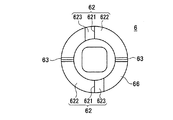
図5に、カム部材6の上面図を示す。図6に、図5に示すカム部材6をA方向から見た側面図を示す。図7に、カム部材6の下面図を示す。図8に、カム部材6の外観上方斜視図を示す。図9に、図5に示すカム部材6をB方向から見た側面図を示す。図10に、カム部材6の外観下方斜視図を示す。
<Composition of cam member>
The configuration of the
FIG. 5 shows a top view of the
図1に示すように、カム部材6は、シリンダ4内に形成された略中空円筒部41内に回動可能な状態で配置されている。図8及び図10に示すように、カム部材6の形状は、略円筒形状である。また、カム部材6のうち円筒部下面はピストン10と当接する当接端面66であり、カム部材6のうち円筒部上面はノブ連結部材19と連結する連結端面65である。当接端面66と連結端面65は平行な面である。
As shown in FIG. 1, the
図8及び図10に示すように、当接端面66には、凹凸形状であるカム面62及びピストン10のピストン係合部101と係合する当接端面係合部63が形成されている。
カム面62は、底部621、摺動テーパ面622及び逃げ部テーパ面623を有する。底部621は、当接端面66から最も奥まった部分に形成されている。また、底部621から当接端面66へ向かってテーパ形状の摺動テーパ面622及び逃げ部テーパ面623が続いている。摺動テーパ面622は、ピストン10のピストン係合部101が当接しスライドする面である。他方逃げ部テーパ面623は、ピストン10のピストン係合部101と当接することはない面である。図9に示すように、摺動テーパ面622の当接端面66に対する角度αは、本実施形態においては約15度である。角度αを約15度と緩い角度にすることにより、ノブ20を回動させピストン10を下(弁閉)方向へ移動させるときのトルクを小さくすることができる。
なお、本実施形態においては角度αを約15度としたが、角度αは角度を緩くすることにより操作トルクを低減できるため、角度αはできるだけ小さい角度であることが好ましい。
As shown in FIGS. 8 and 10, the
The
In the present embodiment, the angle α is set to about 15 degrees. However, the angle α is preferably as small as possible because the operating torque can be reduced by loosening the angle α.
図9に示すように、当接端面係合部63は、摺動テーパ面622の続きに形成されている。当接端面係合部63はピストン10を係合固定するために形成されており、ピストン10が摺動テーパ面622へと戻らないように維持するためのものである。ピストン10のピストン係合部101が当接端面係合部63と係合することにより、流体制御弁1を図4に示す閉弁した状態で維持することができる。本実施形態においては閉弁状態で維持することとしたが、開弁状態において維持することもできる。
As shown in FIG. 9, the contact end
図5に示すように、連結端面65の中心には、ノブ連結部材19が挿入される略四角形状の挿入孔61が形成されている。本実施形態においては略四角形状としたが、ノブ連結部材19と係合できる多角形状であればよい。
また、図1に示すように連結端面65には、第1付勢部材11の一端が係合されている。また、第1付勢部材11の他端は、ノブ連結部材19に形成されている付勢部材固定部191に係合されている。そのため、カム部材6は第1付勢部材11により弁座16方向へ付勢される。そのため、カム部材6はピストン10のピストン係合部101と当接した状態となる。図1においては、カム部材6は、シリンダ4内に形成された内筒段部42に当接した状態にあり、カム部材6は内筒段部42よりも下(弁閉)方向へは移動できない状態にある。
なお、本実施形態においてはカム面62を凹形状としたが、ピストン係合部101を凸形状とした場合には、カム面62を凸形状とする。
As shown in FIG. 5, a substantially
As shown in FIG. 1, one end of the first urging
In the present embodiment, the
<ノブの構成>
図20に、流体制御弁1(全開時)の上面図を示す。図21に、流体制御弁1(全閉時)の上面図を示す。
図1に示すように、流体制御弁1上端には、約90度回動可能なノブ20が形成されている。図20の状態からノブ20を約90度回動させることにより図21のノブ20の状態になる。ノブ20は、長軸Xと短軸Yを有する縦長の六角形形状である。ノブ20が六角形形状であることにより角部201が6か所に形成されている。角部201が6か所に形成されていることにより、作業者が手を滑らせることなくノブ20を回動させることができる。
<Configuration of knob>
FIG. 20 shows a top view of the fluid control valve 1 (when fully opened). FIG. 21 shows a top view of the fluid control valve 1 (when fully closed).
As shown in FIG. 1, a
また、ノブ20は、図21に示すように長軸X及び短軸Yを有する縦長形状である。そのため、図20に示すように開弁状態にある場合は、ノブ20の長軸Xは、第1ポート13及び第2ポート14と同じライン上にある。また、図21の閉弁時にはノブ20の長軸Xは、第1ポート13及び第2ポート14と垂直のライン上にある。したがって、閉弁時と開弁時のノブ20の位置が異なることが外観上一見して認識することができる。そのため、作業者は一目で流体制御弁1の開閉状態を認識することができるため、確認作業の時間を短縮することができ、確認作業に係るコストを低減することができる。
Further, the
また、ノブ20の長軸Xにより約90度回動させるだけのトルクは小さくて流体制御弁1の開弁及び閉弁することができるので、作業者の力が小さくて済む。そのため、ノブ20を小型化することができる。
ノブ20を小型化することができることにより、例えば図示しないが、ノブ20の長軸X及び短軸Yをカム部材6が内蔵される弁本体2の外形寸法よりも小さくすることができる。ノブ20を弁本体2の外形寸法よりも小さくすることで、開弁状態及び閉弁状態のどちらにおいても弁本体2の投影面積からはみ出すことがない。そのため、流体制御弁1を小型化することができる。流体制御弁1を小型化することができることにより、マニホールド(連設)にした場合省スペース化を図ることができる。
Further, since the torque required to rotate about 90 degrees by the long axis X of the
Since the
図1に示すように、ノブ20の中心部に、ノブ連結部材19の上端が固定連結されている。ノブ連結部材19は略円筒形状である。ノブ連結部材19は、ノブ20の中心部に固定連結されており、さらに略円筒形状であるため、ノブ20を回動させた場合、ノブ連結部材19はノブ20に連動して回動する。ノブ連結部材19は、カバー5内の中空部51内に回動可能な状態で配置されている。ノブ連結部材19の下端の形状は四角形形状である。ノブ連結部材19の下端は、カム部材6の中心に形成された挿入孔61に挿入されている。本実施形態においては四角形形状としたが、カム6の挿入孔61の多角形形状に合わせた形状とすることにより、ノブ連結部材19とカム6を連動して回動することができる。ノブ連結部材19の円筒側面には円周状に付勢部材固定部191が形成されており、第1付勢部材11の一端は付勢部材固定部191に係合されている。また、第1付勢部材11の他端はカム部材6の連結端面65に係合されている。
As shown in FIG. 1, the upper end of the
第1付勢部材11の付勢力は、ピストン10に固定されたダイアフラム弁体15を弁座16に押圧するためのものである。第2付勢部材12の付勢力はピストン10をカム部材6に押圧させるためのものである。第1付勢部材11は、図1中下方にある第2付勢部材12の付勢力に打ち勝ちダイアフラム弁体15を弁座16に押圧させる。そのため、第1付勢部材11の付勢力は、第2付勢部材12の付勢力よりも大きい。なお、第1付勢部材11及び第2付勢部材12は、本実施形態においては弾性力を有する金属バネ部材を使用している。
The urging force of the first urging
<流体制御弁の作用効果>
図1の流体制御弁1は開弁状態にある。そのため、第1ポート13から流入した流体は、弁孔17、弁室18を通り、第2ポート14へと流出する。第2ポート14への出力を停止する場合には、図1に示す流体制御弁1のノブ20を約90度回動させ、図4に示す閉弁状態にする。図4の閉弁状態となることにより、弁座16に対してダイアフラム弁体15が当接した状態になるため、第1ポート13から流入した流体は、弁孔17を通ることができないため、第2ポート14へ流体は流入しない。
<Effect of fluid control valve>
The
図1の流体制御弁1の全開状態から、図4の流体制御弁1の全閉状態への変化について図1乃至図4を用いて詳細に説明する。
The change from the fully open state of the
<全開状態>
図1に示す流体制御弁1が全開状態にあるとき、ピストン10のピストン係合部101がカム部材6のカム面62のうち当接端面66から最も奥まった部分である底部621と当接している。ピストン係合部101とカム面62の底部621が当接することにより、ピストン10とカム部材6は最も係合安定した位置になる。そのため、ピストン10を付勢する第2付勢部材12も最も伸びた状態にあり、第2付勢部材12により付勢されているピストン10は最も上がった位置(弁座から離れた位置)になる。
また、カム部材6を付勢する第1付勢部材11は最も伸びた状態にあり、第1付勢部材11により付勢されているカム部材6は最も下がった位置になる。そのため、図1においては、カム部材6は、シリンダ4内に形成された内筒段部42に当接した状態にあり、カム部材6は内筒段部42よりも下(弁閉)方向へは移動できない状態にある。カム部材6は内筒段部42に当接した状態にあり、さらに、ピストン10のピストン係合部101がカム面62の底部621と当接した状態にあるため、第1付勢部材11の付勢力はピストン10に伝達されていない。したがって、ピストン10がカム部材6により押圧され弁座16方向へ移動することがないため、ダイアフラム弁体15は弁座16から離間した状態にある。よって、流体制御弁1は全開状態にある。
<Fully open state>
When the
The
<全閉状態への移行>
図2に示す流体制御弁1は、全開状態から全閉状態へ移行し弁座16とダイアフラム弁体15が当接し始めたときである。具体的には、図2に示すようにノブ20が、本実施形態においては、図中右回りに約70度回動する。それに伴い、ノブ20に固設されたノブ連結部材19が回動し、係合するカム部材6も同様に約70度回動した状態になる。
<Transition to fully closed state>
The
第1に、図1に示す状態からノブ20が回動し始めると、図2に示すようにピストン10は、カム部材6の摺動テーパ面621に沿って押圧され弁座16方向へ移動する。図2に示すように、ノブ20を約70度回動させた状態においては、ピストン10に螺設されたダイアフラム弁体15は、弁座16に当接し始めた状態となる。図2では、第1付勢部材11の付勢力が第2付勢部材12の付勢力よりも勝っているため、第2付勢部材12は付勢され縮んだ状態になりピストン10が弁座16方向へと押圧される。図2では、第1付勢部材11はほぼ伸びきった状態になるため、カム部材6の位置もほとんど図1に示す状態と変化はない。
First, when the
第2に、図2に示す状態からノブ20をさらに回動させ、図3のノブ20が約87度回動させた状態にする。ノブ20及びカム部材6が約87度回動した状態において、ピストン係合部101は、当接端面係合部63に係合される直前の状態である。図2に示す状態においては、ピストン10はダイアフラム弁体15を介して弁座16に当接した状態にあるためピストン10の位置はほとんど変わらない。他方、ノブ20を図2の状態から図3の状態に回動させると、カム部材6はピストン10に押圧されてノブ20方向へ移動する。
Second, the
すなわち、カム部材6が図2の状態から図3の状態にさらに回動されると、ピストン係合部101が摺動テーパ面622を押圧しながら底部621から当接端面66方向へと移動する。ピストン係合部101が当接端面66方向へ移動することにより、カム部材6はピストン10により押し上げられノブ20方向へカム部材6は移動する。カム部材6がノブ20方向へ移動するとき第1付勢部材11はピストン10の押圧力により圧縮された状態となる。
第1付勢部材11は、本実施形態においては図2に示す約70度以上ノブ20を回動させ弁閉状態に近づく場合にのみ圧縮される構造を取る。それにより、ノブ20を約70度回動させた後から高荷重である第1付勢部材11を圧縮すればよい。そのため、大きなトルクが必要となるのは、ノブ20が約70度回動した後からだけとなる。したがって、操作トルクが必要となる範囲を軽減することができるため、作業者の力は小さくて済み作業性をさらに向上させることができる。
That is, when the
In the present embodiment, the first urging
本実施形態においては約70度以上ノブ20を回動させた場合にのみ第1付勢部材11が圧縮される構造としたが、変形例としてノブ20の回動が約90度に近い状態において第1付勢部材11が圧縮される構造とすることができる。それにより、さらに操作トルクが必要となる範囲を軽減することができる。変形例においては、ノブ20の回動が閉弁状態に近い約90度に近いほど第1付勢部材11が圧縮する構造とするのが好ましい。
In the present embodiment, the first urging
第3に、図3に示す状態からノブ20をさらに回動させ、図4の約90度回動させた状態にする。図4に示すように、ノブ20及びカム部材6が約90度回動した状態において、ピストン係合部101は、当接端面係合部63に係合された状態となる。図4に示す状態においては第1付勢部材11がカム部材6を押圧し、ピストン10を弁座16方向へと押圧する。そのため、第1付勢部材11の荷重によりダイアフラム弁体15を弁座16に対して押圧することができ安定したシール力を維持することができる。
また、ピストン係合部101が当接端面係合部63に係合された状態にあるため、図4に示す全閉状態で維持することができる。すわなち、ピストン係合部101と当接端面係合部63が係合することにより、ピストン10及びカム部材6は図4に示す位置から移動することができないため閉弁状態で維持することができる。
また、ノブ20とカム部材6が約90度回動することにより、弁座16とダイアフラム弁体15が当接又は離間できる。すなわち、作業者がノブ20を約90度回動させるだけの簡単な一つの動作で流体制御弁を開閉することができるため、流体制御弁1の開閉を容易にすることができる。さらに、約90度回動させるだけの簡単な一つの動作で流体制御弁1を開閉させることができるため、作動に必要なトルクを軽減することができる。
Thirdly, the
Further, since the
Further, when the
(第2実施形態)
図12及び図13に示す第2実施形態に係る流体制御弁200は、図1乃至図4に示す第1実施形態に係る流体制御弁1と比較して、カム部材及びピストンの形状以外異なるところがない。そのため、第2実施形態においては、第1実施形態と異なるカム部材206及びピストン210について説明することにより、その他の詳細な説明を割愛する。
なお、第2実施形態ではその他の流体制御弁200の詳細な説明を割愛するが、第1実施形態の流体制御弁1と同様の作用、及び効果を有する。
(Second Embodiment)
The
In addition, although detailed description of the other
<流体制御弁の全体構成>
図12には、流体制御弁200(全開時)の断面図を示す。図13には、流体制御弁200(全閉時)の断面図を示す。
本実施形態においては、流体制御弁200を手動弁として説明するが、駆動源を手動以外の電動、又はエア等とすることもできる。
<Overall configuration of fluid control valve>
FIG. 12 shows a cross-sectional view of the fluid control valve 200 (when fully opened). FIG. 13 shows a cross-sectional view of the fluid control valve 200 (when fully closed).
In the present embodiment, the
<ピストンの構成>
図19に、ピストン210の上面図を示す。
第2実施形態におけるピストン210は、第1実施形態におけるピストン10と比較して、ピストン係合部211の個数が異なる。すわなち、第1実施形態のピストン10のピストン係合部101は外周に対して2か所に表れていたが、第2実施形態のピストン210におけるピストン係合部211は外周に対して4か所に表れている。図19に示すように、ピストン210の上面の中心を横断交差するように2本のピストン係合部211が形成されている。ピストン210のピストン係合部211は外周面に対して4か所、90度間隔で形成される。
<Piston configuration>
FIG. 19 shows a top view of the
The
<カム部材の構成>
カム部材206の構成について説明する。
図14に、カム部材206の上面図を示す。図15に、図14に示すカム部材206をC方向から見た側面図を示す。図16に、カム部材206の下面図を示す。図17に、カム部材206の外観上方斜視図を示す。図18に、カム部材206の外観下方斜視図を示す。
<Composition of cam member>
The configuration of the
FIG. 14 shows a top view of the
第2実施形態におけるカム部材206は、第1実施形態におけるカム部材6と比較して、当接端面係合部263の個数、及びカム面250の形状及び個数が異なる。
すわなち、当接端面係合部263は、図16に示すようにカム部材206のうち円筒部下面である当接端面266に対して、90度間隔に均等に形成されている。当接端面係合部263は、90度間隔に形成されているため全周にわたり4か所に形成される。
The
That is, as shown in FIG. 16, the contact end
図15及び図16に示すように、カム面250は、底部251、摺動テーパ面252、逃げ部テーパ面253、及び連結テーパ面254を有する。カム面250は当接端面266に対して、90度間隔に均等に形成されている。カム面250は、90度間隔に形成されているため全周にわたり4か所に形成されている。
As shown in FIGS. 15 and 16, the
図15に示すように、底部251は、当接端面266から最も奥まった部分に形成されている。また、底部251から当接端面266へ向かってテーパ形状の逃げ部テーパ面253及び連結テーパ面254の一端が連結している。連結テーパ面254の他端は摺動テーパ面252に連結している。摺動テーパ面252の他端は当接端面266に連結している。
連結テーパ面254及び摺動テーパ面252は、ピストン210のピストン係合部211が当接しスライドする面である。他方逃げ部テーパ面253は、ピストン210のピストン係合部211と当接することはない面である。
As shown in FIG. 15, the
The connecting
図15に示すように、摺動テーパ面252の当接端面266に対する角度βは、約15度である。角度βを約15度と緩い角度にすることにより、ノブ220を回動させピストン210を下(弁閉)方向へ移動させるときのトルクを小さくすることができる。すなわち、第1付勢部材211を圧縮する範囲を緩い角度とすることができることにより、トルクの掛かりを小さくすることができるためである。それにより、操作トルクが軽減することができ操作性を高めることができる。特に、第2実施形態のように2か所以上にカム面を形成する場合には、連結テーパ面254が形成されていても、第1付勢部材211を圧縮する範囲において約15度の摺動テーパ面252を形成することができれば、トルクの掛かりを小さくすることができる。
As shown in FIG. 15, the angle β of the sliding tapered
また、連結テーパ面254の当接端面266に対する角度θは、約40度である。ピストン係合部211が連結テーパ面254をスライドするのは、ノブ220が約70度回転するまでの間である。ノブ220が約70度回転するまでの間は、ダイアフラム弁体15が弁座16に当接し始めるまでの時間である。ダイアフラム弁体15が弁座16に当接し始めるまでは、第1付勢部材11の付勢力が第2付勢部材12の付勢力よりも勝っているため、トルクは小さくて済む。そのため、連結テーパ面254の当接端面266に対する角度θが約40度の急角度であっても、作業者がノブ220に掛けるトルクは小さくて済む。 本実施形態において角度βを約15度と緩い角度にすることができたのは、カム部材206の円筒部外周にカム面250を形成したことによる。円筒部外周にカム面250を形成することで距離を取ることができるため角度を緩くすることができるためである。また、連結テーパ面254の角度θを急角度にしたことによる。
Further, the angle θ of the connecting tapered
<流体制御弁の作用効果>
第2実施形態における流体制御弁200は、第1実施形態における流体制御弁1と同一の作用効果を有する他、以下の特有の作用効果を有する。
流体制御弁200は、図12に示す開弁状態から図13に示す閉弁状態に移動する際、ノブ220を回動させることにより、カム部材206を同様に回動させる。カム部材206が回動することによりカム部材206のカム面250と当接するピストン210が移動する。流体制御弁200においてはカム面250とピストン210のピストン係合部211は全周にわたり4か所で当接する。そのため、ピストン210が弁座216方向へ移動する際に、4か所のピストン係合部211が4か所のカム面250に押圧されることにより移動する。ピストン210のうち均等に90度間隔で形成された4か所のピストン係合部211が押圧されることによりピストン210は平行移動することができる。そのため、ピストン210に螺設されたダイアフラム弁体215も均等のトルクで押圧され平行移動することができるため、弁座216に対して均等のトルクで押圧する。したがって、弁座216に対してダイアフラム弁体215を確実にシールすることができる。また、4か所で押圧されることによりカム部材206の傾きを防止することができる。
<Effect of fluid control valve>
The
When the
また、カム面250は傾斜角度βを有する摺動テーパ面252及び連結テーパ面254を有する。そのため、ノブ220を約70度回動させるまでは、ピストン係合部211が連結テーパ面254をスライドする。連結テーパ面254をスライドする場合、ダイアフラム弁体15が弁座16に当接し始めるまでは、第1付勢部材11の付勢力が第2付勢部材12の付勢力よりも勝っているため、ノブ220が加えるトルクは小さくて済む。そのため、連結テーパ面254の当接端面266に対する角度θが約40度の急角度であっても、作業者がノブ220に掛けるトルクは小さくて済む。他方、ノブ220を約70度以上回動させると、ピストン係合部211は、摺動テーパ面252をスライドする。摺動テーパ面252は、第1付勢部材211を圧縮する範囲であり、その範囲を緩い角度とすることができるため、トルクの掛かりを小さくすることができる。それにより、操作トルクを軽減することができ操作性を高めることができる。
したがって、カム面250を2以上の傾斜角度を有するテーパ面とすることにより、ノブ220に掛かるトルクを傾斜角度により変更することができる。本実施形態においては、トルクが掛からないノブ220を約70度回動させるまでの傾斜角度を急な角度とすることで、ノブ220に掛かるトルクは結果として小さくなる。また、トルクが掛かるノブ220を約70度以上回動させたときの傾斜角度を緩やかな角度とすることにより、ノブ220に掛かるトルクを小さくすることができる。よって、ノブ220を回転させるトルクを全体を通して小さくすることができる。
なお、実施形態により角度β及び角度θは変更することが可能である。角度β及び角度θを変更することにより、ノブに掛かるトルクを変更することができる。
The
Therefore, the torque applied to the
The angle β and the angle θ can be changed according to the embodiment. The torque applied to the knob can be changed by changing the angle β and the angle θ.
また、カム面250を4か所に形成することにより、ピストン210を押圧するための1か所の負荷が軽減される。カム面250を4か所に形成することにより、カム面250に掛かる1か所当たりの負荷を軽減できるため作業者が容易に流体制御弁1の開閉を行うことができる。すなわち、ピストン210と当接するカム面250が外周に4か所形成されていることにより、カム部材206が安定するためカム部材206の傾きを抑制することができる。カム部材206が安定することにより、弁体15を均等のトルクで弁座16に対して押圧することができる。そのため、弁体15に対してシール力を均一に与えることができ、確実にシールすることができる。
また、カム面205に掛かる1か所当たりの負荷を軽減できるため、カム部材206の耐久性を向上させることができ、カム部材206を有する流体制御弁1の耐久性を向上させることができる。
Further, by forming the
Further, since the load per place on the
尚、本発明は、上記実施の形態に限定されることなく、発明の趣旨を逸脱することのない範囲で色々な応用が可能である。
例えば、本実施形態においては、流体制御弁を手動弁として駆動源をノブを回動させる手動としたが、手動弁のほか駆動源を電動、又はシリンダ等によることができる。例えば、変形例として駆動源を電動とした場合、上記実施例のカム部材及びピストンを用いれば、操作トルクを軽減できる。したがって、駆動源を電動とした場合、小さな電力でモータを作動させることができるため省エネルギーとすることができる。また、エアシリンダを用いた場合も同様にエアの出力を小さくすることができるため省エネルギーとすることができる。また、駆動源を電動又はシリンダとした場合には、手動弁ではないため、ノブに代えてモータ又はシリンダに変える。
Note that the present invention is not limited to the above-described embodiment, and various applications are possible without departing from the spirit of the invention.
For example, in the present embodiment, the fluid control valve is a manual valve and the drive source is manually operated to rotate the knob. For example, when the drive source is electrically driven as a modification, the operation torque can be reduced by using the cam member and the piston of the above embodiment. Therefore, when the drive source is electric, the motor can be operated with a small amount of electric power, so that energy can be saved. Further, when an air cylinder is used, the air output can be similarly reduced, so that energy can be saved. When the drive source is electric or cylinder, it is not a manual valve, so it is replaced with a motor or cylinder instead of a knob.
例えば、本実施形態においてはカム部材6に形成するカムを2か所または4か所形成することを記載したが、カムは1か所又は3か所であってもよい。1か所である場合には、ピストンを動かすためにカムが当接するのが1か所となり作業者の力が必要になる。2か所以上で当接することによりカムがピストンに与える押圧力を分散することができるため、作業者の力が少なくて済む。また、ピストンを動かすためカムに当接するのが1か所となると均等なトルクでピストンを押圧することができない。ピストンを均等なトルクで押圧できないと、弁体が弁座に対して均等なトルクで押圧できず弁座全周に対して均一にシールすることができない。そのため、2か所以上のカムが必要となる。
For example, in the present embodiment, it has been described that two or four cams are formed on the
例えば、本実施形態においてノブ20の形状を六角形形状としたがノブ20の形状は、弁本体2の投影面積の中に収まる形状であり、かつ、縦長の形状のものであればどのような形状であってもよい。例えば、楕円形状、長方形形状、多角形形状であってもよい。
For example, in this embodiment, the shape of the
例えば、本実施形態においてカム部材に当接端面係合部を形成し、ピストンに凸部を形成し、凸部と当接端面係合部が係合することにより流体制御弁を開弁状態又は閉弁状態で維持することができることとしたが、構成を逆としても同様の作用効果を有する。すなわち、当接端面係合部をピストンに形成し、カム部材に凸部を形成しても同様の作用効果を得ることができる。 For example, in this embodiment, a contact end surface engaging portion is formed on the cam member, a convex portion is formed on the piston, and the fluid control valve is opened or closed by engaging the convex portion with the contact end surface engaging portion. Although the valve can be maintained in the closed state, the same effect can be obtained even if the configuration is reversed. That is, even if the contact end surface engaging portion is formed on the piston and the convex portion is formed on the cam member, the same effect can be obtained.
例えば、本実施形態においては、カム面はカム部材の外周に2か所以上形成されていることとしたが、カム面は設計条件によっては外周以外の例えば、内周に形成することもできる。なお、カム面がカム部材の外周に位置することにより、カム面とピストンの当接部を外周に持ってくることができるためカムを安定させることができる。 For example, in the present embodiment, two or more cam surfaces are formed on the outer periphery of the cam member. However, the cam surface may be formed on the inner periphery other than the outer periphery depending on design conditions. Since the cam surface is positioned on the outer periphery of the cam member, the contact portion between the cam surface and the piston can be brought to the outer periphery, so that the cam can be stabilized.
例えば、本実施形態においては、流体制御弁は、ノブとカム部材が約90度回動することにより、弁を開閉することができることとしたが、ノブとカム部材の回動角度は設計により変更することができる。すなわち、ノブとカム部材の回動角度は、摺動テーパ面の傾斜角度により決定される。傾斜角度が大きくなることによりノブとカム部材の回動する回動角度が小さくなり、傾斜角度が小さくなることによりノブとカム部材の回動する回動角度が大きくなる。よって、傾斜角度の設計を変更することによりノブとカム部材の回動角度を変更することができる。なお、傾斜角度の設計変更は、流体制御弁に用いる付勢部材により、操作トルクの掛かり具合が変わるため付勢部材により変更する。 For example, in this embodiment, the fluid control valve can be opened and closed by turning the knob and the cam member about 90 degrees, but the turning angle of the knob and the cam member is changed by the design. can do. That is, the rotation angle of the knob and the cam member is determined by the inclination angle of the sliding taper surface. Increasing the inclination angle decreases the rotation angle at which the knob and the cam member rotate, and decreasing the inclination angle increases the rotation angle at which the knob and the cam member rotate. Therefore, the rotation angle of the knob and the cam member can be changed by changing the design of the inclination angle. The design change of the inclination angle is changed by the biasing member because the degree of operation torque applied varies depending on the biasing member used for the fluid control valve.
1、200 流体制御弁
6、206 カム部材
62、250 カム面
63、263 当接端面係合部
10、210 ピストン
11、211 第1付勢部材
12、212 第2付勢部材
13、213 第1ポート
14、214 第2ポート
15、215 ダイアフラム弁体
16、216 弁座
20、220 ノブ
1,200 Fluid control valve 6,206 Cam member 62,250 Cam surface 63,263 Contact end surface engaging portion 10,210 Piston 11,211 First biasing member 12,212 Second biasing member 13,213
Claims (7)
前記ノブ連結部材と前記ピストンの間に、前記ノブ連結部材と前記ピストンとを連結するカム部材が介在していること、
前記カム部材は、シリンダ内に弁座方向及び反弁座方向に移動可能に配置されると共に、前記ノブ連結部材と一体的に回動可能に配置されていること、
前記カム部材のノブ連結部材側の端面に対して当接した状態で配置されて前記カム部材を弁座方向に付勢する第1付勢部材を有すること、
前記ピストンを反弁座方向に付勢する第2付勢部材を有すること、
前記シリンダ内の、弁が全開状態の場合に前記カム部材に当接する位置に形成され、前記カム部材の弁座方向への移動を制限する内筒段部を有すること、
(1)前記カム部材の前記ピストンと当接する当接端面に、凹形状のカム面が形成されていること、及び、前記ピストンの前記カム面と当接する部分には凸形状のピストン係合部が形成されていること、又は、(2)前記カム部材の前記ピストンと当接する当接端面に、凸形状のカム面が形成されていること、及び、前記ピストンの前記カム面と当接する部分には凹形状のピストン係合部が形成されていること、のいずれか一つの組み合わせを有すること、
前記カム部材は、弁が全開状態である場合には、前記第1付勢部材に付勢されて前記内筒段部に当接し、前記第1付勢部材の荷重を前記ピストンに伝達せず、弁が全閉状態である場合には、前記内筒段部から離間して前記第1付勢部材に押圧され、前記ピストンを弁座方向へと押圧し、前記第1付勢部材の荷重により前記弁体を前記弁座に押圧すること、
を特徴とする流体制御弁。 First and second ports are formed, wherein a body portion formed with a valve seat in a flow path of the fluid between the first port communicating with said second port, a cylinder connected to the body portion, the cylinder a piston disposed in a slidable state in the valve seat direction and Hanben seat direction within, coupled to the piston, a valve body for controlling the flow of fluid contact or apart from the valve seat, wherein A cover coupled to the cylinder, a knob coupling member disposed in a rotatable manner through the cover and the cover, and the knob coupling member coupled to a portion projecting to the outside of the cover; by rotating in conjunction with the knob coupling member, the fluid control valve and a knob for moving the piston in the closing direction of the valve body,
Between the said knob coupling member piston, the cam member for connecting the said knob coupling member piston is interposed,
The cam member is disposed in the cylinder so as to be movable in the valve seat direction and the counter valve seat direction, and is disposed so as to be rotatable integrally with the knob connecting member .
A first biasing member disposed in contact with the end surface of the cam member on the knob connecting member side and biasing the cam member in the valve seat direction;
Having a second urging member for urging the piston in the direction opposite to the valve seat;
An inner cylinder step portion that is formed at a position in contact with the cam member when the valve is fully opened in the cylinder and restricts movement of the cam member in the valve seat direction ;
(1) A concave cam surface is formed on the abutting end surface of the cam member that abuts on the piston, and a convex piston engaging portion is formed on a portion of the piston that abuts on the cam surface. Or (2) a convex cam surface is formed on the contact end surface of the cam member that contacts the piston, and a portion that contacts the cam surface of the piston. Has a concave piston engaging part, having any one combination,
When the valve is fully open, the cam member is urged by the first urging member and abuts against the inner cylinder step portion, and the load of the first urging member is not transmitted to the piston. When the valve is in a fully closed state, it is separated from the inner cylinder step portion and is pressed by the first biasing member to press the piston in the valve seat direction, and the load of the first biasing member Pressing the valve body against the valve seat by
A fluid control valve characterized by.
前記カム部材に前記カム面が2か所以上形成されていること、
を特徴とする流体制御弁。 The fluid control valve according to claim 1,
Two or more cam surfaces are formed on the cam member;
A fluid control valve characterized by.
前記カム面は2以上の傾斜角度を有するテーパ面を有すること、
を特徴とする流体制御弁。 In the fluid control valve according to claim 1 or 2,
The cam surface has a tapered surface having an inclination angle of 2 or more;
A fluid control valve characterized by.
前記流体制御弁は、前記ノブと前記カム部材が約90度回動することにより、前記弁座に前記弁体が当接又は離間すること、
を特徴とする流体制御弁。 The fluid control valve according to any one of claims 1 to 3,
The fluid control valve is configured such that the valve body comes into contact with or separates from the valve seat when the knob and the cam member rotate about 90 degrees.
A fluid control valve characterized by.
前記カム部材の前記当接端面に前記ピストンが閉方向にスライドした際に前記ピストン係合部と係合する当接端面係合部が形成されていること、
を特徴とする流体制御弁。 The fluid control valve according to any one of claims 1 to 4,
A contact end surface engaging portion that engages with the piston engaging portion when the piston slides in the closing direction is formed on the contact end surface of the cam member;
A fluid control valve characterized by.
前記ボディ部と前記シリンダと前記カバーにより弁本体を形成し、
前記ノブは、前記カム部材が内蔵される前記弁本体の外形寸法よりも小さいこと、
を特徴とする流体制御弁。 The fluid control valve according to any one of claims 1 to 5,
A valve body is formed by the body part, the cylinder and the cover,
The knob is smaller than an outer dimension of the valve body in which the cam member is incorporated;
A fluid control valve characterized by.
前記ピストンの移動を前記ノブによる駆動に代えて、モータ駆動又はシリンダ駆動を用いること、
を特徴とする流体制御弁。 The fluid control valve according to any one of claims 1 to 6,
Using a motor drive or a cylinder drive instead of driving the piston by the knob;
A fluid control valve characterized by.
Priority Applications (2)
| Application Number | Priority Date | Filing Date | Title |
|---|---|---|---|
| JP2011098743A JP5602673B2 (en) | 2011-04-26 | 2011-04-26 | Fluid control valve |
| PCT/JP2012/061057 WO2012147775A1 (en) | 2011-04-26 | 2012-04-25 | Fluid control valve |
Applications Claiming Priority (1)
| Application Number | Priority Date | Filing Date | Title |
|---|---|---|---|
| JP2011098743A JP5602673B2 (en) | 2011-04-26 | 2011-04-26 | Fluid control valve |
Publications (3)
| Publication Number | Publication Date |
|---|---|
| JP2012229755A JP2012229755A (en) | 2012-11-22 |
| JP2012229755A5 JP2012229755A5 (en) | 2013-07-11 |
| JP5602673B2 true JP5602673B2 (en) | 2014-10-08 |
Family
ID=47072293
Family Applications (1)
| Application Number | Title | Priority Date | Filing Date |
|---|---|---|---|
| JP2011098743A Active JP5602673B2 (en) | 2011-04-26 | 2011-04-26 | Fluid control valve |
Country Status (2)
| Country | Link |
|---|---|
| JP (1) | JP5602673B2 (en) |
| WO (1) | WO2012147775A1 (en) |
Families Citing this family (1)
| Publication number | Priority date | Publication date | Assignee | Title |
|---|---|---|---|---|
| KR102331094B1 (en) * | 2020-09-28 | 2021-12-01 | 김창호 | Water supply system for sanitary ceramics |
Family Cites Families (4)
| Publication number | Priority date | Publication date | Assignee | Title |
|---|---|---|---|---|
| DE693636C (en) * | 1936-04-25 | 1940-07-16 | Auergesellschaft Akt Ges | Manually operated auxiliary air valve on high altitude breathing apparatus |
| US2606450A (en) * | 1949-12-08 | 1952-08-12 | Crane Co | Valve actuating mechanism |
| JPS5590863U (en) * | 1978-12-18 | 1980-06-23 | ||
| US5103857A (en) * | 1989-10-18 | 1992-04-14 | Kohler Co. | Self closing valve assembly |
-
2011
- 2011-04-26 JP JP2011098743A patent/JP5602673B2/en active Active
-
2012
- 2012-04-25 WO PCT/JP2012/061057 patent/WO2012147775A1/en active Application Filing
Also Published As
| Publication number | Publication date |
|---|---|
| WO2012147775A1 (en) | 2012-11-01 |
| JP2012229755A (en) | 2012-11-22 |
Similar Documents
| Publication | Publication Date | Title |
|---|---|---|
| JP6774931B2 (en) | Actuator with dual drive | |
| US10415711B2 (en) | Mechanical energized sealing ball valve with a single item | |
| US7971599B2 (en) | Air-operated valve | |
| KR101730637B1 (en) | Valve assembly for a fluid injection valve and fluid injection valve | |
| US7526993B2 (en) | Fluid pressure cylinder apparatus having throttle valve | |
| JP6594007B2 (en) | Vacuum valve | |
| KR20050058440A (en) | Pinch valve | |
| TW201640043A (en) | Stepper motor operated balanced flow control valve | |
| CA2908438C (en) | Rotatable control device with axial translation | |
| WO2006051655A1 (en) | Handle with torque limiter and fluid controller having the handle | |
| US20080237509A1 (en) | Piping Member | |
| JP5602673B2 (en) | Fluid control valve | |
| US5957428A (en) | Composite-action butterfly valve | |
| JP5712053B2 (en) | Valve actuator | |
| KR20160012171A (en) | A pressurised fluid container | |
| JP2013540952A (en) | Face-sealing annular valve for fluid-operated equipment | |
| JP5467066B2 (en) | Manual valve | |
| JP5319969B2 (en) | Ball valve | |
| JP5220485B2 (en) | Valve structure and two-way and three-way valves using the same | |
| WO2005093306A1 (en) | Torque-limiter-equipped handle and fluid controller having the handle | |
| JP2006009847A (en) | Flow rate controller | |
| KR101407905B1 (en) | A piston type opening and closing valve with a linear flow path | |
| JP4989676B2 (en) | Pressure regulating valve | |
| CN108351043B (en) | Vacuum angle valve with slide way driving mechanism | |
| JP5911668B2 (en) | Valve actuator mounting structure |
Legal Events
| Date | Code | Title | Description |
|---|---|---|---|
| A521 | Written amendment |
Effective date: 20130528 Free format text: JAPANESE INTERMEDIATE CODE: A523 |
|
| A621 | Written request for application examination |
Effective date: 20130528 Free format text: JAPANESE INTERMEDIATE CODE: A621 |
|
| A131 | Notification of reasons for refusal |
Free format text: JAPANESE INTERMEDIATE CODE: A131 Effective date: 20140212 |
|
| A521 | Written amendment |
Free format text: JAPANESE INTERMEDIATE CODE: A523 Effective date: 20140414 |
|
| TRDD | Decision of grant or rejection written | ||
| A01 | Written decision to grant a patent or to grant a registration (utility model) |
Effective date: 20140819 Free format text: JAPANESE INTERMEDIATE CODE: A01 |
|
| A61 | First payment of annual fees (during grant procedure) |
Effective date: 20140820 Free format text: JAPANESE INTERMEDIATE CODE: A61 |
|
| R150 | Certificate of patent (=grant) or registration of utility model |
Ref document number: 5602673 Free format text: JAPANESE INTERMEDIATE CODE: R150 Country of ref document: JP |