JP5591526B2 - Solid oxide cell and solid oxide cell stack - Google Patents
Solid oxide cell and solid oxide cell stack Download PDFInfo
- Publication number
- JP5591526B2 JP5591526B2 JP2009274262A JP2009274262A JP5591526B2 JP 5591526 B2 JP5591526 B2 JP 5591526B2 JP 2009274262 A JP2009274262 A JP 2009274262A JP 2009274262 A JP2009274262 A JP 2009274262A JP 5591526 B2 JP5591526 B2 JP 5591526B2
- Authority
- JP
- Japan
- Prior art keywords
- solid oxide
- cell
- oxygen electrode
- manganese
- oxide cell
- Prior art date
- Legal status (The legal status is an assumption and is not a legal conclusion. Google has not performed a legal analysis and makes no representation as to the accuracy of the status listed.)
- Expired - Fee Related
Links
Images


Classifications
-
- H—ELECTRICITY
- H01—ELECTRIC ELEMENTS
- H01M—PROCESSES OR MEANS, e.g. BATTERIES, FOR THE DIRECT CONVERSION OF CHEMICAL ENERGY INTO ELECTRICAL ENERGY
- H01M8/00—Fuel cells; Manufacture thereof
- H01M8/10—Fuel cells with solid electrolytes
- H01M8/12—Fuel cells with solid electrolytes operating at high temperature, e.g. with stabilised ZrO2 electrolyte
-
- H—ELECTRICITY
- H01—ELECTRIC ELEMENTS
- H01M—PROCESSES OR MEANS, e.g. BATTERIES, FOR THE DIRECT CONVERSION OF CHEMICAL ENERGY INTO ELECTRICAL ENERGY
- H01M4/00—Electrodes
- H01M4/86—Inert electrodes with catalytic activity, e.g. for fuel cells
- H01M4/8647—Inert electrodes with catalytic activity, e.g. for fuel cells consisting of more than one material, e.g. consisting of composites
- H01M4/8652—Inert electrodes with catalytic activity, e.g. for fuel cells consisting of more than one material, e.g. consisting of composites as mixture
-
- H—ELECTRICITY
- H01—ELECTRIC ELEMENTS
- H01M—PROCESSES OR MEANS, e.g. BATTERIES, FOR THE DIRECT CONVERSION OF CHEMICAL ENERGY INTO ELECTRICAL ENERGY
- H01M4/00—Electrodes
- H01M4/86—Inert electrodes with catalytic activity, e.g. for fuel cells
- H01M4/8647—Inert electrodes with catalytic activity, e.g. for fuel cells consisting of more than one material, e.g. consisting of composites
- H01M4/8657—Inert electrodes with catalytic activity, e.g. for fuel cells consisting of more than one material, e.g. consisting of composites layered
-
- H—ELECTRICITY
- H01—ELECTRIC ELEMENTS
- H01M—PROCESSES OR MEANS, e.g. BATTERIES, FOR THE DIRECT CONVERSION OF CHEMICAL ENERGY INTO ELECTRICAL ENERGY
- H01M4/00—Electrodes
- H01M4/86—Inert electrodes with catalytic activity, e.g. for fuel cells
- H01M4/88—Processes of manufacture
- H01M4/8825—Methods for deposition of the catalytic active composition
- H01M4/8846—Impregnation
-
- H—ELECTRICITY
- H01—ELECTRIC ELEMENTS
- H01M—PROCESSES OR MEANS, e.g. BATTERIES, FOR THE DIRECT CONVERSION OF CHEMICAL ENERGY INTO ELECTRICAL ENERGY
- H01M4/00—Electrodes
- H01M4/86—Inert electrodes with catalytic activity, e.g. for fuel cells
- H01M4/90—Selection of catalytic material
- H01M4/9016—Oxides, hydroxides or oxygenated metallic salts
- H01M4/9025—Oxides specially used in fuel cell operating at high temperature, e.g. SOFC
- H01M4/9033—Complex oxides, optionally doped, of the type M1MeO3, M1 being an alkaline earth metal or a rare earth, Me being a metal, e.g. perovskites
-
- H—ELECTRICITY
- H01—ELECTRIC ELEMENTS
- H01M—PROCESSES OR MEANS, e.g. BATTERIES, FOR THE DIRECT CONVERSION OF CHEMICAL ENERGY INTO ELECTRICAL ENERGY
- H01M8/00—Fuel cells; Manufacture thereof
- H01M8/10—Fuel cells with solid electrolytes
- H01M8/12—Fuel cells with solid electrolytes operating at high temperature, e.g. with stabilised ZrO2 electrolyte
- H01M8/124—Fuel cells with solid electrolytes operating at high temperature, e.g. with stabilised ZrO2 electrolyte characterised by the process of manufacturing or by the material of the electrolyte
- H01M8/1246—Fuel cells with solid electrolytes operating at high temperature, e.g. with stabilised ZrO2 electrolyte characterised by the process of manufacturing or by the material of the electrolyte the electrolyte consisting of oxides
- H01M8/1253—Fuel cells with solid electrolytes operating at high temperature, e.g. with stabilised ZrO2 electrolyte characterised by the process of manufacturing or by the material of the electrolyte the electrolyte consisting of oxides the electrolyte containing zirconium oxide
-
- H—ELECTRICITY
- H01—ELECTRIC ELEMENTS
- H01M—PROCESSES OR MEANS, e.g. BATTERIES, FOR THE DIRECT CONVERSION OF CHEMICAL ENERGY INTO ELECTRICAL ENERGY
- H01M8/00—Fuel cells; Manufacture thereof
- H01M8/24—Grouping of fuel cells, e.g. stacking of fuel cells
-
- Y—GENERAL TAGGING OF NEW TECHNOLOGICAL DEVELOPMENTS; GENERAL TAGGING OF CROSS-SECTIONAL TECHNOLOGIES SPANNING OVER SEVERAL SECTIONS OF THE IPC; TECHNICAL SUBJECTS COVERED BY FORMER USPC CROSS-REFERENCE ART COLLECTIONS [XRACs] AND DIGESTS
- Y02—TECHNOLOGIES OR APPLICATIONS FOR MITIGATION OR ADAPTATION AGAINST CLIMATE CHANGE
- Y02E—REDUCTION OF GREENHOUSE GAS [GHG] EMISSIONS, RELATED TO ENERGY GENERATION, TRANSMISSION OR DISTRIBUTION
- Y02E60/00—Enabling technologies; Technologies with a potential or indirect contribution to GHG emissions mitigation
- Y02E60/30—Hydrogen technology
- Y02E60/36—Hydrogen production from non-carbon containing sources, e.g. by water electrolysis
-
- Y—GENERAL TAGGING OF NEW TECHNOLOGICAL DEVELOPMENTS; GENERAL TAGGING OF CROSS-SECTIONAL TECHNOLOGIES SPANNING OVER SEVERAL SECTIONS OF THE IPC; TECHNICAL SUBJECTS COVERED BY FORMER USPC CROSS-REFERENCE ART COLLECTIONS [XRACs] AND DIGESTS
- Y02—TECHNOLOGIES OR APPLICATIONS FOR MITIGATION OR ADAPTATION AGAINST CLIMATE CHANGE
- Y02E—REDUCTION OF GREENHOUSE GAS [GHG] EMISSIONS, RELATED TO ENERGY GENERATION, TRANSMISSION OR DISTRIBUTION
- Y02E60/00—Enabling technologies; Technologies with a potential or indirect contribution to GHG emissions mitigation
- Y02E60/30—Hydrogen technology
- Y02E60/50—Fuel cells
-
- Y—GENERAL TAGGING OF NEW TECHNOLOGICAL DEVELOPMENTS; GENERAL TAGGING OF CROSS-SECTIONAL TECHNOLOGIES SPANNING OVER SEVERAL SECTIONS OF THE IPC; TECHNICAL SUBJECTS COVERED BY FORMER USPC CROSS-REFERENCE ART COLLECTIONS [XRACs] AND DIGESTS
- Y02—TECHNOLOGIES OR APPLICATIONS FOR MITIGATION OR ADAPTATION AGAINST CLIMATE CHANGE
- Y02P—CLIMATE CHANGE MITIGATION TECHNOLOGIES IN THE PRODUCTION OR PROCESSING OF GOODS
- Y02P70/00—Climate change mitigation technologies in the production process for final industrial or consumer products
- Y02P70/50—Manufacturing or production processes characterised by the final manufactured product
Description
本発明は、分解生成物の形成が低減された固体酸化物セル(SOCs)に関する。より詳細には、本発明は、ランタン−ストロンチウム−マンガナイト(LSM)を含む酸素電極の分解が抑制されている固体酸化物型燃料電池及び固体酸化物型電解セルに関する。 The present invention relates to solid oxide cells (SOCs) with reduced formation of decomposition products. More specifically, the present invention relates to a solid oxide fuel cell and a solid oxide electrolytic cell in which decomposition of an oxygen electrode containing lanthanum-strontium-manganite (LSM) is suppressed.
固体酸化物セルはまた、可逆性の固体酸化物セルとしても知られており、固体酸化物型燃料電池として、及び固体酸化物型電解セルとして使用することができる。固体酸化物セルは基本的に3つの異なる層からなり、酸化物イオンを誘導する電解質である中間層は気密性であって、電極層の間に挟まれている。電極層は多孔質であって、電子とイオンを誘導し、各固体酸化物セルは酸素電極と燃料電極を有する。固体酸化物型燃料電池を以下に説明する。 Solid oxide cells are also known as reversible solid oxide cells and can be used as solid oxide fuel cells and as solid oxide electrolysis cells. A solid oxide cell is basically composed of three different layers, and an intermediate layer, which is an electrolyte for inducing oxide ions, is hermetic and is sandwiched between electrode layers. The electrode layer is porous and induces electrons and ions, and each solid oxide cell has an oxygen electrode and a fuel electrode. The solid oxide fuel cell will be described below.
固体酸化物型燃料電池(SOFC)は、電気化学反応から直接電気を発生する高温燃料電池であり、その全体は固体状態の酸化物材料、典型的にはセラミックスから構成される。この構成により、SOFCsは、他の種類の燃料電池、例えばPEM燃料電池よりもずっと高い温度で運転することが可能となる。典型的な運転温度は600℃〜1000℃である。 A solid oxide fuel cell (SOFC) is a high temperature fuel cell that generates electricity directly from an electrochemical reaction, and is entirely composed of a solid state oxide material, typically ceramics. This configuration allows SOFCs to operate at much higher temperatures than other types of fuel cells, such as PEM fuel cells. Typical operating temperatures are 600 ° C to 1000 ° C.
固体酸化物型燃料電池において酸素電極はカソードであり、そこでは酸素から酸素イオンへの還元が生じる。燃料電極はアノードであり、そこでは水素から水素イオンへの、そして水への酸化が起こる。電気化学エネルギーの変換が固体酸化物型燃料電池中で生じ、それにより、外部から供給された燃料(アノード側)と酸化剤(カソード側)から電力が発生される。そのため、これらは電解質の存在下において電極で反応する。 In a solid oxide fuel cell, the oxygen electrode is the cathode where reduction of oxygen to oxygen ions occurs. The fuel electrode is the anode where oxidation of hydrogen to hydrogen ions and to water occurs. Electrochemical energy conversion occurs in the solid oxide fuel cell, thereby generating power from externally supplied fuel (anode side) and oxidant (cathode side). Therefore, they react at the electrode in the presence of electrolyte.
通常、アノードを流れる反応物は、水素又はメタンのような燃料である。メタンが燃料として使用される場合、アノード表面において内部改質が起こり、それにより
蒸気の存在下で、メタンは水素と一酸化炭素に改質される。水素はその後電気化学反応において転化される。カソードを流れる酸化剤は、通常空気又は酸素である。
Typically, the reactant flowing through the anode is a fuel such as hydrogen or methane. When methane is used as a fuel, internal reforming occurs at the anode surface, thereby reforming methane to hydrogen and carbon monoxide in the presence of steam. The hydrogen is then converted in an electrochemical reaction. The oxidant flowing through the cathode is usually air or oxygen.
固体酸化物型燃料電池は、固体酸化物型電解セル(SOEC)が水素又は合成ガス(水素、H2及び一酸化炭素、COの混合物)を生成する、H2O及び/又はCO2の電気分解を逆行するように、可逆性モードで運転することができる。 A solid oxide fuel cell is an H 2 O and / or CO 2 electricity in which a solid oxide electrolysis cell (SOEC) produces hydrogen or synthesis gas (a mixture of hydrogen, H 2 and carbon monoxide, CO). It can be operated in a reversible mode to reverse the decomposition.
固体酸化物型電解セル中においては、酸素電極はアノードであり、そこでは酸素イオンの酸素への酸化が起こる。燃料電極はカソードであり、そこでは水から水素への還元が起こる。 In the solid oxide electrolysis cell, the oxygen electrode is the anode, where oxidation of oxygen ions to oxygen occurs. The fuel electrode is the cathode where the reduction of water to hydrogen occurs.
従来の複合酸素電極は、ランタン−ストロンチウム−マンガナイト(LSM)のような電子誘導材料、及びイットリア安定化ジルコニア(YSZ)のような酸素イオン誘導材料を用いて製造される。これら酸素電極は、YSZのような酸素イオン誘導固体酸化物から製造された密な電解質の表面上に堆積される。 Conventional composite oxygen electrodes are manufactured using an electron induction material such as lanthanum-strontium-manganite (LSM) and an oxygen ion induction material such as yttria stabilized zirconia (YSZ). These oxygen electrodes are deposited on the surface of a dense electrolyte made from an oxygen ion derived solid oxide such as YSZ.
還元−酸化反応は、主として、電極、電解質、及び酸素又は水素が相互に接触する三元相の境界で起こる。そのため、三元相の境界は、電極と電解質との間の界面で生じる反応の影響を受ける。従って、効率的なガスの拡散と、電解質と電極との間の高められた接触面積が重要である。 The reduction-oxidation reaction occurs mainly at the ternary phase boundary where the electrode, electrolyte, and oxygen or hydrogen are in contact with each other. Therefore, the boundary of the ternary phase is affected by the reaction that occurs at the interface between the electrode and the electrolyte. Therefore, efficient gas diffusion and increased contact area between the electrolyte and the electrode are important.
酸素電極の性能は、主として、酸素電極−電解質の界面に存在する抵抗によって決定される。界面の抵抗を低減し、かつ三元相の境界面の発生を高めることが望ましい。そのために、電極の分極抵抗は低減され、酸素電極の性能全体が向上する。セルの運転温度と酸素電極チャンバ中の酸素分圧もまた、酸素電極の性能に影響を与える。上記因子の不適切な制御が、三元相の境界における分解生成物の形成を招き、そのためSOFC又はSOECの性能が低減する場合がある。 The performance of the oxygen electrode is mainly determined by the resistance present at the oxygen electrode-electrolyte interface. It is desirable to reduce the interface resistance and increase the occurrence of ternary phase boundaries. Therefore, the polarization resistance of the electrode is reduced and the overall performance of the oxygen electrode is improved. The cell operating temperature and the oxygen partial pressure in the oxygen electrode chamber also affect the performance of the oxygen electrode. Inappropriate control of the above factors can lead to the formation of decomposition products at the boundaries of the ternary phase, which can reduce the performance of the SOFC or SOEC.
酸素電極と電解質との間の高められた接触抵抗による既知の分解生成物は、ジルコニウム酸ランタン、La2Zr2O7(LZOと略す)である。この望ましくない分解生成物は、ランタン−ストロンチウム−マンガナイト(LSM)酸素電極と、イットリ
ア安定化ジルコニア(YSZ)電解質との間の界面で形成され、そしてその形成は、例えば、SOFCの焼結中などの、高温でのSOFCの加熱によって増加する。LZOの形成はまた、セル試験中の高い分極のもとでも増加する。
A known decomposition product due to the increased contact resistance between the oxygen electrode and the electrolyte is lanthanum zirconate, La 2 Zr 2 O 7 (abbreviated as LZO). This undesirable decomposition product is formed at the interface between the lanthanum-strontium-manganite (LSM) oxygen electrode and the yttria-stabilized zirconia (YSZ) electrolyte, and the formation is, for example, during SOFC sintering. It is increased by heating the SOFC at a high temperature. LZO formation also increases under high polarization during cell testing.
その他の公知の分解生成物は、ジルコニウム酸ストロンチウム(SZO)、及びLa−Zr−Si、及びSr−Zr−Siの酸化物化合物類である。 Other known decomposition products are strontium zirconate (SZO), and La-Zr-Si and Sr-Zr-Si oxide compounds.
LSM−YSZの分解は、過酷な試験条件下、すなわち低温及び高い電流密度でのセル分解に対して主に寄与することが確認された。バーフォード等(Barfod et al.)の固体状態の電気化学の進歩、材料科学に関する第26回リソ国際シンポジウム、リソ国立研究所、ロスキルデ、第121頁(2005年)(非特許文献1、Barfod et al. Solid State Electrochemistry Proc. 26th Riso International Symposium on Materials Science, Riso National Laboratory, Roskilde, page 121 (2005))は、分解速度が、固体酸化物型燃料電池中のカソード側に対する酸素分圧に非常に依存し、分解速度は純粋な酸素中よりも空気中の方が著しく高いことも指摘している。 It was confirmed that the degradation of LSM-YSZ mainly contributes to the cell degradation under severe test conditions, i.e. low temperature and high current density. Barford et al., Progress in Solid State Electrochemistry, 26th Litho International Symposium on Materials Science, Lizo National Laboratory, Roskilde, p. 121 (2005) (Non-Patent Document 1, Barford et al.) al. Solid State Electrochemistry Proc. 26 th Riso International Symposium on Materials Science, Riso National Laboratories, Roschild, Page 121 It is also pointed out that the decomposition rate is significantly higher in air than in pure oxygen.
クッサー,ディー等の固体状態のイオン性78(1995年)79(非特許文献2、Kuscer, D. et al. Solid State Ionics 78 (1995) 79)、によって、LZOとLaシリケートの両方が、LaMnO3/YSZ境界面において1450℃でのエージング中に形成することが報告されている。
According to Kusser, Dee et al., Solid state ionicity 78 (1995) 79 (Non-Patent
研究(エィ・ハンゲン等の電気化学学会会議、vol.2007−07、No.1、第301〜309頁(非特許文献3、A. Hagen et al. Electrochemical Society Transactions, vol. 2007−07, No. 1, page 301−309))は、LZOが、長時間試験された固体酸化物型燃料電池中で、局所的に、そして好ましくはLSM/電解質接触領域に分布されたナノサイズの粒子として存在することを示している。カソードと電解質との間の境界面におけるナノサイズのジルコニウム酸ストロンチウム(SZO)粒子の形成もまた可能であろう。LZO相及びSZO相の両方は、ジルコニア電解質と比較した場合のそれらの低い導電性に起因する絶縁特性を有し、そしてそれらの存在によりカソードと電解質の電気接触が弱まる。 Research (Conference of Electrochemical Society of Ai Hangen et al., Vol. 2007-07, No. 1, pp. 301-309 (Non-Patent Document 3, A. Hagen et al. Electrochemical Society Transactions, vol. 2007-07, No. 1, page 301-309)), LZO is present in nano-sized particles distributed locally and preferably in the LSM / electrolyte contact area in solid oxide fuel cells that have been tested for a long time It shows that Formation of nano-sized strontium zirconate (SZO) particles at the interface between the cathode and the electrolyte would also be possible. Both LZO and SZO phases have insulating properties due to their low electrical conductivity when compared to zirconia electrolytes, and their presence weakens the electrical contact between the cathode and the electrolyte.
ジルコニウム酸ランタンの形成を抑制するべく、様々な試みがなされてきた。米国特許第7141329B2号明細書(特許文献1)は、多孔質なイオン導電性酸化セリウムの膜コーティングを備えた、拡張された三元相の境界の微小構造を有する電極を開示している。このコーティングは、CeO2ポリマーゾル又は粒子ゾルから選択される一種またはより多くのドープされた酸化物ゾルから作製され、ゾル−ゲル法を用いて低温で製造でき、その結果、望ましくない境界面反応生成物の生成を防止することができる。 Various attempts have been made to suppress the formation of lanthanum zirconate. U.S. Pat. No. 7,141,329 B2 discloses an electrode having an extended ternary phase boundary microstructure with a porous ion conductive cerium oxide membrane coating. This coating is made from one or more doped oxide sols selected from CeO 2 polymer sols or particle sols and can be produced at low temperatures using a sol-gel process, resulting in undesirable interface reactions Product formation can be prevented.
Umemura, F.等は、電極材料の焼結と反応を調査するために、劣化した空気電極の微視的特性を評価した(非特許文献4、電気化学及び工業物理化学(電気化学と工業物理化学(日本)第63巻第2号(1995年2月5日)第128頁から第133頁)(Denki Kagaku Oyobi Kogyo Butsuri Kagaku (Electrochemistry and Industrial Physical Chemistry)(Japan) v63:2.(5 Feb 1995) page 128−133))。La0.9Sr0.1MnO3と、8%Y2O3−安定化ジルコニアを添加した時に得られる8YSZによってハーフセルを作製して、測定した。YSZの添加により、電極と電解質との間の境界面におけるLa2Zr2O7の生成が制御された。 Umemura, F.M. Evaluated the microscopic properties of degraded air electrodes in order to investigate the sintering and reaction of electrode materials (Non-Patent Document 4, Electrochemistry and Industrial Physical Chemistry (Electrochemistry and Industrial Physical Chemistry (Japan) Vol. 63 No. 2 (February 5, 1995) pp. 128 to 133) (Denki Kagaku Oyobi Kogyo Butsuri Kagaku (Electrochemistry and Industrial Physi. -133)). A half cell was prepared and measured using 8YSZ obtained when La 0.9 Sr 0.1 MnO 3 and 8% Y 2 O 3 -stabilized zirconia were added. The addition of YSZ controlled the production of La 2 Zr 2 O 7 at the interface between the electrode and the electrolyte.
固体酸化物型燃料電池のためのLa1−xSrxMnO3の電気化学特性、及びジルコニウム酸ランタンの形成もまた、Lee,H.M.によって研究された(非特許文献5、材料の化学と物理、2003年、V77、N3(1月30日)、第639〜649頁(Materials Chemistry and Physics, 2003, V77,N3 (Jan 30), page 639−646))。固体酸化物型燃料電気のカソード材料のためのLa1−xSrxMnO3中のSrの最適量が、電荷移動抵抗、電気伝導度、及び電解質との反応性を観察することによって研究された。電解質とLa1−xSrxBO3(B=Cr、Mn、Co)との間の反応性が調査され、Srの置換量が50モル%の時に二次相、La2Zr2O7は形成されないことがわかった。
The electrochemical properties of La 1-x Sr x MnO 3 for solid oxide fuel cells and the formation of lanthanum zirconate are also described in Lee, H. et al. M.M. (
LZOとSZOの形成を制御するためのその他公知の試みは、SOFC中に、余剰のMnを含有するLSMカソードを利用することを含む。製造中、LSMカソードは、マンガンにおいて超化学量論的であるため、マンガン酸化物が二次相としてカソード中に存在する。 Other known attempts to control the formation of LZO and SZO include utilizing LSM cathodes containing excess Mn in the SOFC. During manufacture, LSM cathodes are superstoichiometric in manganese, so manganese oxide is present in the cathode as a secondary phase.
日本特許出願第5190183号明細書(特許文献2)は、イットリア安定化ジルコニアを含有する燃料電極を有する固体酸化物型燃料電池を開示している。続いて、粉末化イットリア安定化ジルコニア粉末とMnOx粉末とのスラリーが製造され、このスラリーが、固体電解質の表面に塗布され、その後か焼される。そのため、マンガンが、燃料電極、固体電解質、及び気相からなる三相域中に存在する。燃料電極の活性化分極はより小さくなり、SOFCセルの出力は向上した。 Japanese Patent Application No. 5190183 (Patent Document 2) discloses a solid oxide fuel cell having a fuel electrode containing yttria-stabilized zirconia. Subsequently, a slurry of powdered yttria stabilized zirconia powder and MnOx powder is produced, and this slurry is applied to the surface of the solid electrolyte and then calcined. Therefore, manganese exists in a three-phase region composed of a fuel electrode, a solid electrolyte, and a gas phase. The activation polarization of the fuel electrode became smaller and the output of the SOFC cell improved.
LSMとYSZの化学反応性及び相互拡散が、Roosmalen, J.A.M.等によって研究された(非特許文献6、固体状態イオン、52(1992年)、第303〜312頁(Roosmalen, J.A.M. et.al, Solid State Ionics 52 (1992) page 303 - 312))。彼らは、反応生成物のLZOとSZOの形成を観察し、得られたLZOとSZOを含む反応層が、SOFCのオーム抵抗と分極の両方を損失させる結果を招き得ることを提言している。彼らは、抵抗損失が反応生成物の低い導電性に起因し、そして、分分極の損失が、カソード、電解質、及び酸素間の三相境界における酸素移動の阻止に起因することを示唆している。LSM中の(La、Sr):Mn比を減少させることによって、La及び/又はSrの活性を低減することが提案されている。 The chemical reactivity and interdiffusion of LSM and YSZ is described by Roosmalen, J. et al. A. M.M. (Non-patent Document 6, Solid State Ion, 52 (1992), pages 303 to 312 (Roosmalen, JA et al., Solid State Ionics 52 (1992), pages 303-312). )). They observe the formation of the reaction products LZO and SZO and suggest that the resulting reaction layer containing LZO and SZO can result in loss of both SOFC ohmic resistance and polarization. They suggest that the resistance loss is due to the low conductivity of the reaction product and that the polarization loss is due to the blocking of oxygen transfer at the three-phase boundary between the cathode, electrolyte, and oxygen. . It has been proposed to reduce the activity of La and / or Sr by reducing the (La, Sr): Mn ratio in LSM.
しかしながら、マンガンを超化学量論量で導入するこれらの工程は、ジルコニウム酸塩の形成を低減させるのに効果的であることを示しているが、固体酸化物セルが長期間強い分極で運転される場合に、それら中のLSMを含む酸素電極とYSZ電解質との間の三元相の境界における界面でLZOとSZOとの形成を回避するには十分ではない。 However, these steps of introducing superstoichiometric amounts of manganese have been shown to be effective in reducing zirconate formation, but solid oxide cells have been operated with strong polarization for long periods of time. In that case, it is not sufficient to avoid the formation of LZO and SZO at the interface at the ternary phase boundary between the oxygen electrode containing LSM and the YSZ electrolyte.
従って、本発明の課題は、より劣化しにくい固体酸化物セルを提供することである。 Accordingly, an object of the present invention is to provide a solid oxide cell that is less prone to degradation.
本発明のさらなる課題は、向上された長期性能を示す固体酸化物セルを提供することである。 It is a further object of the present invention to provide a solid oxide cell that exhibits improved long-term performance.
これらの課題、並びにその他の課題は、
− 燃料電極層を燃料電極支持層の上に堆積させる工程、
− 安定化ジルコニアを含む電解質層を燃料電極層の上に堆積させて、燃料電極支持体、燃料電極及び電解質のアセンブリを提供する工程、
− 任意に、上記の燃料電極支持体、燃料電極及び電解質のアセンブリを一緒に焼結して、予備焼結されたハーフセルを提供する工程、
− 上記の予備焼結されたハーフセルの上記の電解質層の上に、一つ以上の酸素電極層を堆積させて、完全な固体酸化物セルを提供する工程であって、その一つ以上の酸素電極層の少なくとも一つがランタン−ストロンチウム−マンガナイト、及び安定化ジルコニアを含む、前記工程、
− 上記の一つ以上の酸素電極層を、上記の予備焼結されたハーフセルと一緒に焼結して、焼結された完全な固体酸化物セルを提供する工程、
− 上記の焼結された完全な固体酸化物セルの一つ以上の酸素電極層をマンガンで含浸して、マンガン含浸固体酸化物セルを提供する工程、
を含む方法によって得ることができる固体酸化物セルを提供することによって達成される。
These issues, as well as other issues,
-Depositing a fuel electrode layer on the fuel electrode support layer;
Depositing an electrolyte layer comprising stabilized zirconia on the fuel electrode layer to provide a fuel electrode support, fuel electrode and electrolyte assembly;
Optionally sintering the fuel electrode support, fuel electrode and electrolyte assembly described above together to provide a pre-sintered half-cell;
-Depositing one or more oxygen electrode layers on the electrolyte layer of the pre-sintered half-cell to provide a complete solid oxide cell, the one or more oxygen At least one of the electrode layers comprising lanthanum-strontium-manganite and stabilized zirconia,
-Sintering the one or more oxygen electrode layers together with the pre-sintered half cell to provide a sintered complete solid oxide cell;
-Impregnating one or more oxygen electrode layers of the sintered complete solid oxide cell with manganese to provide a manganese-impregnated solid oxide cell;
This is accomplished by providing a solid oxide cell that can be obtained by a process comprising:
予備焼結されたハーフセルを提供するために、燃料電極支持体、燃料電極、及び電解質のアセンブリを一緒に焼結することは任意である。もし、焼結が行われない場合には、燃料電極支持体、燃料電極、及び電解質のアセンブリはハーフセルを与える。 It is optional to sinter the fuel electrode support, fuel electrode, and electrolyte assembly together to provide a pre-sintered half-cell. If sintering is not performed, the fuel electrode support, fuel electrode, and electrolyte assembly provides a half cell.
この場合、後続の工程は次の通りである。
− ハーフセルの電解質層の上に、一つ以上の酸素電極層を堆積して、完全な固体酸化物セルを提供する工程であって、その一つ以上の酸素電極層の少なくとも一つがランタン−ストロンチウム−マンガナイト及び安定化ジルコニアの複合体を含む、前記工程、
− 上記の一つ以上の酸素電極層を上記のハーフセルと一緒に焼結して、焼結された完全な固体酸化物セルを提供する工程、及び、
− 上記の焼結された完全な固体酸化物セルの一つ以上の酸素電極層をマンガンで含浸して、マンガン含浸固体酸化物セルを提供する工程。
In this case, the subsequent steps are as follows.
-Depositing one or more oxygen electrode layers on the electrolyte layer of the half cell to provide a complete solid oxide cell, wherein at least one of the one or more oxygen electrode layers is lanthanum-strontium; Said process comprising a complex of manganite and stabilized zirconia,
-Sintering said one or more oxygen electrode layers together with said half cell to provide a sintered complete solid oxide cell; and
-Impregnating one or more oxygen electrode layers of the sintered complete solid oxide cell with manganese to provide a manganese-impregnated solid oxide cell.
従って、本発明は、燃料電極支持体層の上に堆積された燃料電極層及びこの燃料電極層の上に堆積された、安定化ジルコニアを含む電解質層、及び該電解質層の上に堆積された一つ以上の酸素電極層であって、その一つ以上の酸素電極層の少なくとも一つがランタン−ストロンチウム−マンガナイト及び安定化ジルコニアの複合体を含む固体酸化物セルを包含し、そして燃料電極、燃料電極支持体層、電解質層及び一つ以上の酸素電極層が同時に焼結され、そして焼結された一つ以上の酸素電極層がその後更にマンガンで含浸される。 Accordingly, the present invention provides a fuel electrode layer deposited on a fuel electrode support layer, an electrolyte layer comprising stabilized zirconia deposited on the fuel electrode layer, and deposited on the electrolyte layer. One or more oxygen electrode layers, wherein at least one of the one or more oxygen electrode layers includes a solid oxide cell comprising a composite of lanthanum-strontium-manganite and stabilized zirconia, and a fuel electrode; The fuel electrode support layer, the electrolyte layer and the one or more oxygen electrode layers are simultaneously sintered, and the sintered one or more oxygen electrode layers are then further impregnated with manganese.
従って、本発明は、次の工程を含む、固体酸化物セルの製造方法を包含する。
− 燃料電極支持層の上に、燃料電極層を堆積する工程、
− 安定化ジルコニアを含む電解質層を燃料電極層の上に堆積させて、燃料電池支持体、燃料電極及び電解質のアセンブリを提供する工程、
− 任意に、上記の燃料電極支持体、燃料電極及び電解質のアセンブリを一緒に焼結して、予備焼結されたハーフセルを提供する工程、
− 上記の予備焼結されたハーフセルの電解質層の上に、一つ以上の酸素電極層を堆積させて、完全な固体酸化物セルを提供する工程であって、その一つ以上の酸素電極層の少なくとも一つが、ランタン−ストロンチウム−マンガナイト及び安定化ジルコニアの複合体を含む、前記工程、
− 上記の一つ以上の酸素電極層を上記の予備焼結されたハーフセルと一緒に焼結して、焼結された完全な固体酸化物セルを提供する工程、
− 上記の焼結された完全な固体酸化物セルの一つ以上の酸素電極層をマンガンで含浸して、マンガン含浸固体酸化物セルを提供する工程。
Therefore, this invention includes the manufacturing method of a solid oxide cell including the following processes.
-Depositing a fuel electrode layer on the fuel electrode support layer;
Depositing an electrolyte layer comprising stabilized zirconia on the fuel electrode layer to provide a fuel cell support, fuel electrode and electrolyte assembly;
Optionally sintering the fuel electrode support, fuel electrode and electrolyte assembly described above together to provide a pre-sintered half-cell;
-Depositing one or more oxygen electrode layers on the pre-sintered half-cell electrolyte layer to provide a complete solid oxide cell, the one or more oxygen electrode layers; Wherein at least one of the above comprises a complex of lanthanum-strontium-manganite and stabilized zirconia,
-Sintering the one or more oxygen electrode layers together with the pre-sintered half-cell to provide a sintered complete solid oxide cell;
-Impregnating one or more oxygen electrode layers of the sintered complete solid oxide cell with manganese to provide a manganese-impregnated solid oxide cell.
さらに、本発明は、一つ以上の固体酸化物型燃料電池、あるいは一つ以上の固体酸化物型電解セルを含む、固体酸化物セルスタックを提供する。 Furthermore, the present invention provides a solid oxide cell stack including one or more solid oxide fuel cells or one or more solid oxide electrolytic cells.
本発明の実施態様において、一つ以上の酸素電極層の少なくとも一つは、ランタン−ストロンチウム−マンガナイト及び安定化ジルコニアの複合体を含み、マンガンと、上記のランタン−ストロンチウム−マンガナイト中のランタン及びストロンチウムとの原子比は1より大きい。この実施態様は、上記並びに下記の実施態様のいずれかと組み合わせることができる。 In an embodiment of the present invention, at least one of the one or more oxygen electrode layers comprises a complex of lanthanum-strontium-manganite and stabilized zirconia, and manganese and lanthanum in the lanthanum-strontium-manganite described above. And the atomic ratio with strontium is greater than 1. This embodiment can be combined with any of the above and below described embodiments.
本発明の実施態様において、ジルコニアは、イットリア、スカンジア(scandia)、マグネシア又は酸化カルシウムで安定化される。 In an embodiment of the invention, the zirconia is stabilized with yttria, scandia, magnesia or calcium oxide.
本発明の好ましい実施態様においては、ジルコニアはイットリアで安定化される。 In a preferred embodiment of the invention, zirconia is stabilized with yttria.
本発明の実施態様において、マンガンによる一つ以上の酸素電極層の含浸は、上記の一つ以上の酸素電極層の少なくとも一つが所定量のマンガンで含浸されるまで繰り返し行われる。 In an embodiment of the present invention, impregnation of one or more oxygen electrode layers with manganese is repeated until at least one of the one or more oxygen electrode layers is impregnated with a predetermined amount of manganese.
本発明の実施態様において、マンガンによる上記の一つ以上の酸素電極層の含浸は、ランタン−ストロンチウム−マンガナイトと安定化ジルコニアの複合体を含む上記の酸素電極層が所定量のマンガンで含浸されるまで、繰り返し行われる。この実施態様は、上記又は下記で開示される実施態様のいずれかと組み合わせることができる。 In an embodiment of the present invention, the impregnation of the one or more oxygen electrode layers with manganese is performed by impregnating the oxygen electrode layer including a complex of lanthanum-strontium-manganite and stabilized zirconia with a predetermined amount of manganese. Until it is done. This embodiment can be combined with any of the embodiments disclosed above or below.
本発明の実施態様において、上記の一つ以上の酸素電極層の少なくとも一つの表面上に、マンガンは0.5〜5mg/cm2の濃度で含浸される。 In an embodiment of the present invention, manganese is impregnated at a concentration of 0.5 to 5 mg / cm 2 on at least one surface of the one or more oxygen electrode layers.
本発明の実施態様において、マンガンは、マンガン(II)塩の水溶液を用いて含浸される。 In an embodiment of the invention, manganese is impregnated using an aqueous solution of manganese (II) salt.
本発明の実施態様において、上記の塩は硝酸塩、硫酸塩、又は塩化物である。 In an embodiment of the invention, the salt is a nitrate, sulfate, or chloride.
本発明の実施態様において、上記の一つ以上の酸素電極層は、スクリーン印刷、噴霧、テープ成形又は噴霧熱分解によって、電解質層の上に堆積される。本発明の実施態様において、固体酸化物セルスタックは一つ以上の固体酸化物セルを含む。この固体酸化物セルスタックは、少なくとも二つの固体酸化物セルを含むことができる。 In an embodiment of the invention, the one or more oxygen electrode layers are deposited on the electrolyte layer by screen printing, spraying, tape molding or spray pyrolysis. In an embodiment of the present invention, the solid oxide cell stack includes one or more solid oxide cells. The solid oxide cell stack can include at least two solid oxide cells.
本発明の実施態様において、固体酸化物セルは固体酸化物型燃料電池又は固体酸化物型電解セルである。 In an embodiment of the present invention, the solid oxide cell is a solid oxide fuel cell or a solid oxide electrolytic cell.
本発明の固体酸化物セルは、酸素電極と電解質との間に、マンガンリッチな界面を有することを特徴とする。マンガンは過剰に存在しており、これは電解質、酸素電極及び酸素ガスの間の三元相の境界に局所的に存在させるか、あるいは酸素電極と電解質の間に配置された層として存在させることができる。 The solid oxide cell of the present invention is characterized by having a manganese-rich interface between the oxygen electrode and the electrolyte. Manganese is present in excess, which must be present locally at the ternary phase boundary between the electrolyte, oxygen electrode and oxygen gas, or as a layer placed between the oxygen electrode and the electrolyte. Can do.
層として、あるいは三元相の境界に局所的にマンガンが過剰に存在することによって、酸素電極/電解質境界面は、燃料電池スタックの運転中に酸素電極中のLSMと電解質中の安定化ジルコニアとの間の反応性が低減することによって劣化するのを効果的に防止する。ジルコン酸塩形成の危険性が低減される。 Oxygen electrode / electrolyte interface, due to the presence of excess manganese locally as a layer or at the boundary of the ternary phase, causes the LSM in the oxygen electrode and the stabilized zirconia in the electrolyte during operation of the fuel cell stack. It effectively prevents deterioration due to a decrease in reactivity between the two. The risk of zirconate formation is reduced.
本発明は固体酸化物セルにおける劣化を低減させることに関する。本発明は固体酸化物型燃料電池及び固体酸化物型電解セル中のLSM/NSZ(安定化ジルコニア(ここでNは異なる安定化成分を示す))タイプの複合電極を含むランタン−ストロンチウム−マンガナイト(LSM)型の電解質における劣化の抑制に関連する。 The present invention relates to reducing degradation in solid oxide cells. The present invention relates to a lanthanum-strontium-manganite comprising a composite electrode of LSM / NSZ (stabilized zirconia, where N represents a different stabilizing component) type in solid oxide fuel cells and solid oxide electrolytic cells. It relates to the suppression of degradation in (LSM) type electrolytes.
劣化は、LSM適用範囲の損失及び三重相境界長さの損失として確認されていた。これは、絶縁相LZO、SZO及びSr−Zr−Si酸化物化合物のうちの少なくとも一つの形成に起因する個々のLSM/電解質接触領域の寸法減少及び三元相の境界長さにおける減少によって観察される。絶縁相は、局所的に、そして好ましくはLSM/電解質接触領域中に分布したナノ粒子として存在する。 Degradation has been identified as LSM coverage loss and triple phase boundary length loss. This is observed by a decrease in the size of the individual LSM / electrolyte contact regions and a decrease in the boundary length of the ternary phase due to the formation of at least one of the insulating phases LZO, SZO and Sr-Zr-Si oxide compounds. The The insulating phase is present locally and preferably as nanoparticles distributed in the LSM / electrolyte contact region.
本発明の固体酸化物セルは、固体酸化物型燃料電池又は固体酸化物型電解セルのいずれとしての使用にも適している。これは、従来の酸素電極を有する固体酸化物セルと比較した時、低減された濃度の絶縁相LZO(最重要)、SZO及びLa−Zr−Si又はSr−Zr−Si酸化物化合物の一つ以上を有する。低減された濃度は、強い分極及び延長された運転期間のような過酷な運転条件に曝される前と後の両方で観察される。 The solid oxide cell of the present invention is suitable for use as either a solid oxide fuel cell or a solid oxide electrolytic cell. This is one of the reduced concentrations of insulating phase LZO (most important), SZO and La-Zr-Si or Sr-Zr-Si oxide compounds when compared to a solid oxide cell with a conventional oxygen electrode. Have the above. Reduced concentrations are observed both before and after exposure to harsh operating conditions such as strong polarization and extended operating periods.
更に、本発明の固体酸化物セルの酸素電極と電解質との間の接着性は、LSM粒子が安定化ジルコニア電解質表面から剥離するのが防止されるため、向上する。 Furthermore, the adhesion between the oxygen electrode and the electrolyte of the solid oxide cell of the present invention is improved because the LSM particles are prevented from peeling from the stabilized zirconia electrolyte surface.
固体酸化物セルは、絶縁相の形成におけるこの低減を容易にするために特定の方法で改質された。この改質は、酸素電極層を堆積させてから酸素電極層をマンガン溶液に含浸させた後で固体酸化物セルを焼結することを含む。 The solid oxide cell was modified in a specific way to facilitate this reduction in the formation of the insulating phase. This modification includes sintering the solid oxide cell after depositing the oxygen electrode layer and then impregnating the oxygen electrode layer with a manganese solution.
本発明の固体酸化物セルの製造を、以下に詳述する。 The production of the solid oxide cell of the present invention is described in detail below.
燃料電極支持体層は、好ましくはテープ成形によって製造される。燃料電極層は、燃料電極支持層の上に、例えば噴霧や従来公知のその他の方法によって堆積される。燃料電極層と燃料電極支持体層は、固体酸化物セルの製造に有用な通常の材料のいずれかであることができる。 The fuel electrode support layer is preferably manufactured by tape molding. The fuel electrode layer is deposited on the fuel electrode support layer by, for example, spraying or other conventionally known methods. The fuel electrode layer and the fuel electrode support layer can be any of the conventional materials useful for the production of solid oxide cells.
固体酸化物セルに関して、燃料電極支持体層は、例えば、Ni−NSZ複合体であることができ、ここで、NはMg、Ca、Y、Sc、又は当該技術において公知のその他の元素、例えば、Ce及びGdを意味することができる。 For solid oxide cells, the fuel electrode support layer can be, for example, a Ni-NSZ composite, where N is Mg, Ca, Y, Sc, or other elements known in the art, such as , Ce and Gd.
あるいはまた、燃料電極層はFe−Cr合金粒子をベースとする多孔質金属であることができる。更には、この燃料電極層はドープされたSrTiO3のようなセラミックであることができる。固体酸化物型燃料電池としては好ましくは、Ni−NSZ複合体及びFe−Cr合金粒子をベースとする多孔質金属であり、そして固体酸化物型電解セルとして好ましいのは、ドープされたSrTiO3のようなセラミックである。 Alternatively, the fuel electrode layer can be a porous metal based on Fe-Cr alloy particles. Furthermore, the fuel electrode layer can be a ceramic such as doped SrTiO 3 . The solid oxide fuel cell is preferably a porous metal based on Ni-NSZ composite and Fe-Cr alloy particles, and the preferred solid oxide electrolysis cell is doped SrTiO 3 . Such a ceramic.
固体酸化物セルについて、燃料電極層は、例えば、(1)NがMg、Ca、Y、Scを意味する、Ni−NSZ複合体であり、及び(2)ドープされたSrTiO3のようなセラミックである。 For solid oxide cells, the fuel electrode layer is, for example, (1) a Ni—NSZ composite where N means Mg, Ca, Y, Sc, and (2) a ceramic such as doped SrTiO 3. It is.
固体酸化物型燃料電池として好ましいのは、1)及び2)であり、そして固体酸化物型電解セルとしては2)である。 Preferred as the solid oxide fuel cell are 1) and 2), and 2) as the solid oxide electrolytic cell.
電解質層は燃料電極層の上に堆積される。電解質層は、一般にNSZと略される安定化ジルコニアであり、ここでNは安定化させる元素を意味する。Nはイットリウム、スカンジウム、マグネシウム又はカルシウムを意味する。固体酸化物型燃
料電池及び固体酸化物型電解セルの両方に関して、好ましくはイットリア安定化ジルコニア(YSZ)であり、そしてより好ましくはY0.15Zr0.85O1.925(TZ8Yと略される)である。
An electrolyte layer is deposited on the fuel electrode layer. The electrolyte layer is a stabilized zirconia generally abbreviated as NSZ, where N means an element to be stabilized. N means yttrium, scandium, magnesium or calcium. For both solid oxide fuel cells and solid oxide electrolysis cells, it is preferably yttria stabilized zirconia (YSZ) and more preferably Y 0.15 Zr 0.85 O 1.925 (abbreviated TZ8Y). Is).
堆積は、噴霧、スクリーン印刷、噴霧熱分解、テープ成形、又は当該技術で公知のその他の方法によって好ましく行うことができる。 Deposition can preferably be performed by spraying, screen printing, spray pyrolysis, tape forming, or other methods known in the art.
燃料電極支持体層、燃料電極層、及び電解質のアセンブリは、一般にハーフセルと呼ばれる。これらの構成要素に基づいて得られるハーフセルは、任意に焼結することができ、予備焼結とも呼ばれる。典型的には、このハーフセルは焼結されて、予備焼結されたハーフセルを提供する。焼結は、1200℃を超える温度で行うことができる。この焼結工程を含むことの利点は、後続の工程のために強いハーフセルを形成させることであって、その場合には酸素電極の適用方法及び焼結温度を広い範囲内で選択することができる、。 The assembly of fuel electrode support layer, fuel electrode layer, and electrolyte is commonly referred to as a half cell. The half cells obtained on the basis of these components can be optionally sintered and are also called presintering. Typically, the half cell is sintered to provide a pre-sintered half cell. Sintering can be performed at temperatures in excess of 1200 ° C. The advantage of including this sintering step is to form a strong half-cell for the subsequent steps, in which case the oxygen electrode application method and sintering temperature can be selected within a wide range. ,.
一つ以上の酸素電極層は、その後ハーフセル又は予備焼結されたハーフセルの電解質層の上に堆積され、そして、少なくとも一つの酸素電極層は、ランタン−ストロンチウム−マンガナイトと、NSZの複合体(LSM−NSZ)を含み、ここでNは、Mg、Ca、Y、Sc及びそれら元素の混合物からなる群から選択される。LSMはマンガンに関して化学量論的又は超化学量論的である。マンガンは、そのため、酸素電極組成物中に過剰に存在し得る。好ましくは、マンガンは10重量%までの量で過剰に存在する。 One or more oxygen electrode layers are then deposited on the half-cell or pre-sintered half-cell electrolyte layer, and the at least one oxygen electrode layer comprises a lanthanum-strontium-manganite and NSZ composite ( LSM-NSZ), where N is selected from the group consisting of Mg, Ca, Y, Sc and mixtures of these elements. LSM is stoichiometric or superstoichiometric with respect to manganese. Manganese can therefore be present in excess in the oxygen electrode composition. Preferably, manganese is present in excess in an amount up to 10% by weight.
化学量論的とは、原子比Mn/(La+Sr)が1であること、すなわち、材料は、元素の濃度が完全なペロブスカイトの一つに匹敵するように合成されることを意味する。構造体(La、Sr)中のA部位になる元素、及びB部位(Mn)になる元素の等量(原子%)がある。 Stoichiometric means that the atomic ratio Mn / (La + Sr) is 1, that is, the material is synthesized so that the concentration of the element is comparable to one of the perfect perovskites. There is an equivalent amount (atomic%) of an element that becomes the A site in the structure (La, Sr) and an element that becomes the B site (Mn).
超化学量論的とは、化合物が、化学量論的化合物の1:1の比に関して過剰のMnが存在するように、すなわち、マンガンと、ランタン及びストロンチウムとの比(Mn/(La+Sr))が1より大きく(原子%)なるように合成されることを意味する。
この不均衡によって材料中に空のA部位及び/又は少量の二次Mn酸化物相、例えばMnO、MnO2又はその他が形成される。
Superstoichiometric means that the compound has an excess of Mn with respect to the 1: 1 ratio of the stoichiometric compound, ie the ratio of manganese to lanthanum and strontium (Mn / (La + Sr)). Is synthesized to be larger than 1 (atomic%).
This imbalance results in the formation of empty A sites and / or small amounts of secondary Mn oxide phases such as MnO, MnO 2 or others in the material.
酸素電極層として適当なLSM−NSZ層の例は50重量%LSM−50重量%YSZである。 An example of an LSM-NSZ layer suitable as an oxygen electrode layer is 50 wt% LSM-50 wt% YSZ.
完全な固体酸化物セルは、一つ以上の酸素電極層がハーフセル又は予備焼結されたハーフセルの電解質層の上に堆積される時に得られる。 A complete solid oxide cell is obtained when one or more oxygen electrode layers are deposited on the half-cell or pre-sintered half-cell electrolyte layer.
酸素電極層はまた、二つ又はより多くの異なる組成の層からなる複合多層であり、ここで少なくとも一つの層はLSM−NSZの複合体であり、ここでNは例えばイットリウムである。二元酸素電極層の一例は、LSM−NSZの第一の酸素電極層と、LSMの第二の酸素電極層からなることができるである。本発明の好ましい実施態様において、Nはイットリウムである。 The oxygen electrode layer is also a composite multilayer composed of two or more layers of different composition, wherein at least one layer is a composite of LSM-NSZ, where N is, for example, yttrium. An example of a binary oxygen electrode layer can consist of a first oxygen electrode layer of LSM-NSZ and a second oxygen electrode layer of LSM. In a preferred embodiment of the invention, N is yttrium.
酸素電極層は、ハーフセル又は予備焼結されたハーフセルの電解質層の上に、異なる方法、例えばスクリーン印刷、テープ成形、噴霧、噴霧熱分解又は当該技術において公知のその他の類似方法によって堆積させることができる。 The oxygen electrode layer may be deposited on the half-cell or pre-sintered half-cell electrolyte layer by different methods such as screen printing, tape forming, spraying, spray pyrolysis or other similar methods known in the art. it can.
LSM−NSZの複合体である酸素電極層は、5〜40ミクロンの厚さを有することができ、そしてLSM−NSZの複合体ではない酸素電極層は10〜100ミクロンの厚さを有することができる。電解質層は1〜20ミクロンの厚さを有することができる。燃料電極層は1〜20ミクロンの厚さを有することができ、燃料電極支持体層は、200〜1000ミクロンの厚さを有することができる。 The oxygen electrode layer that is a composite of LSM-NSZ can have a thickness of 5-40 microns, and the oxygen electrode layer that is not a composite of LSM-NSZ can have a thickness of 10-100 microns. it can. The electrolyte layer can have a thickness of 1 to 20 microns. The fuel electrode layer can have a thickness of 1 to 20 microns and the fuel electrode support layer can have a thickness of 200 to 1000 microns.
所定量の一つ以上の酸素電極層を電解質層の上に堆積させた後、一つ以上の酸素電極層が堆積されたハーフセル又は予備焼結されたハーフセルは焼結されて、焼結された完全な固体酸化物セルを提供する。この工程は酸素電極の電解質に対する接着性を確実にするために重要である。焼結は900〜1300℃、好ましくは950〜1100℃の温度で行われる。 After depositing a predetermined amount of one or more oxygen electrode layers on the electrolyte layer, the half cell on which the one or more oxygen electrode layers are deposited or the pre-sintered half cell is sintered and sintered. A complete solid oxide cell is provided. This step is important to ensure the adhesion of the oxygen electrode to the electrolyte. Sintering is performed at a temperature of 900-1300 ° C, preferably 950-1100 ° C.
焼結後、焼結された完全な固体酸化物セルの一つ以上の酸素電極層は、マンガンで含浸される。この含浸は、マンガン塩、例えば、マンガン(II)塩の水溶液であることができるマンガン溶液を用いて行うことができる。この塩は、例えば硝酸塩、硫酸塩、塩化物又はマンガン塩の水溶液の形成に適当なその他の慣用の塩であることができる。好ましくは硝酸塩である。マンガンで含浸された固体酸化物セルが得られる。 After sintering, one or more oxygen electrode layers of the sintered complete solid oxide cell are impregnated with manganese. This impregnation can be performed using a manganese solution, which can be an aqueous solution of a manganese salt, for example, a manganese (II) salt. This salt can be any other conventional salt suitable for the formation of aqueous solutions of, for example, nitrates, sulfates, chlorides or manganese salts. Nitrate is preferred. A solid oxide cell impregnated with manganese is obtained.
Mn(II)の酸素電極上への含浸はまた、燃焼合成工程によっても行うことができる。例えば次の通りである:水溶液中でグリシンとMn−硝酸塩を結合させる前駆体を、セルの加熱中に酸素電極上に滴下することができる。この前駆体はまた、過剰な水を蒸発させるために加熱され、それによって、粘性液を生じさせることができる。約180℃への更なる加熱は前駆体の液を自動発火させて、Mn(II)を酸素電極中に含浸させる。 Impregnation of Mn (II) on the oxygen electrode can also be performed by a combustion synthesis process. For example: A precursor that binds glycine and Mn-nitrate in aqueous solution can be dropped onto the oxygen electrode during heating of the cell. This precursor can also be heated to evaporate excess water, thereby producing a viscous liquid. Further heating to about 180 ° C. causes the precursor liquid to ignite automatically and impregnates the Mn (II) into the oxygen electrode.
硝酸マンガンが、酸素電極/電解質界面において、1cm2当たり0.5〜5mgMnに相当する、0.5〜5mg/cm2の濃度で酸素電極層の表面上に堆積されたものが本発明の好ましい実施態様である。この濃度において、マンガンは、電解質、酸素電極、及び酸素ガスの三元相の境界において局部的に過剰に存在するか、あるいは酸素電極と電解質との間に配置する層として存在する。より好ましくは、0.5〜3mg/cm2の濃度で堆積される。 It is preferred according to the invention that manganese nitrate is deposited on the surface of the oxygen electrode layer at a concentration of 0.5 to 5 mg / cm 2 , corresponding to 0.5 to 5 mg Mn per cm 2 at the oxygen electrode / electrolyte interface. This is an embodiment. At this concentration, manganese is present locally in excess at the boundary of the electrolyte, oxygen electrode, and oxygen gas ternary phase, or as a layer disposed between the oxygen electrode and the electrolyte. More preferably, it is deposited at a concentration of 0.5-3 mg / cm 2 .
含浸は、酸素電極層の表面上に所定濃度のマンガンを得るために繰り返し行うことができる。必要であれば、真空で行うことができる。 Impregnation can be repeated to obtain a predetermined concentration of manganese on the surface of the oxygen electrode layer. If necessary, it can be performed in vacuum.
マンガンによる含浸後、得られた固体酸化物セルは、300℃までの温度で加熱することによって乾燥される。乾燥後、得られた固体酸化物セルは、固体酸化物型燃料電池スタック又は固体酸化物電解質スタックにおいて使用するのに適している。 After impregnation with manganese, the resulting solid oxide cell is dried by heating at temperatures up to 300 ° C. After drying, the resulting solid oxide cell is suitable for use in a solid oxide fuel cell stack or a solid oxide electrolyte stack.
本発明の方法によって得られた固体酸化物型燃料電池を固体酸化物型燃料電池スタックに適用することによって、過酷な運転条件に曝された後の、酸素電極、
電解質及びガスの間の三元相の境界中の分解生成物LZO、SZO、La−Zr−Si及びSr−Zr−Si少なくとも一つの含有量が低減される。
By applying the solid oxide fuel cell obtained by the method of the present invention to a solid oxide fuel cell stack, an oxygen electrode after being exposed to harsh operating conditions,
The content of at least one of the decomposition products LZO, SZO, La-Zr-Si and Sr-Zr-Si in the ternary phase boundary between the electrolyte and the gas is reduced.
例1:過剰濃度のマンガンを含む固体酸化物セルの製造
酸素電極/電解質界面が過剰濃度のMnを含む固体酸化物セルは、以下の工程で製造される。
Example 1 Production of Solid Oxide Cell Containing Excess Concentration Manganese A solid oxide cell in which the oxygen electrode / electrolyte interface contains an excessive concentration of Mn is produced by the following steps.
(1) 燃料電極支持体層(AS)をテープ成形する、
(2) 燃料電極層(A)を燃料電極支持体層の表面上に噴霧する、
(3) 8%Y2O3−安定化ジルコニア(TZ8Y)の10ミクロン電解質層(E)を、燃料電極層の表面上に噴霧して、ハーフセルを得る、
(4) ハーフセルを1200℃を超える温度で焼結する、
(5) 電解質層の表面上に、20〜30ミクロンの厚さのLSM−YSZ酸素電極層をスクリーン印刷する、
(6) ハーフセルと、このハーフセルの上に堆積されたLSM−YSZ酸素電極層とを同時に焼結する、
(7) 100mlの蒸留水中に10gのMn−硝酸塩を溶解させることによって調製されたMn−硝酸塩水溶液を用いて、酸素電極層を含浸する。含浸されたセルにおいて0.5〜5mgMn/cm2の濃度が得られるまで含浸工程を繰り返す、
(8) 含浸されたセルを80℃の温度で加熱することによって乾燥して、固体酸化物セル得る。
(1) Tape the fuel electrode support layer (AS),
(2) spraying the fuel electrode layer (A) on the surface of the fuel electrode support layer;
(3) A 10 micron electrolyte layer (E) of 8% Y 2 O 3 -stabilized zirconia (TZ8Y) is sprayed on the surface of the fuel electrode layer to obtain a half cell.
(4) Sinter the half cell at a temperature exceeding 1200 ° C.
(5) Screen-printing an LSM-YSZ oxygen electrode layer having a thickness of 20 to 30 microns on the surface of the electrolyte layer;
(6) Sintering the half cell and the LSM-YSZ oxygen electrode layer deposited on the half cell simultaneously.
(7) The oxygen electrode layer is impregnated with an aqueous Mn-nitrate solution prepared by dissolving 10 g of Mn-nitrate in 100 ml of distilled water. Repeating the impregnation step until a concentration of 0.5-5 mg Mn / cm 2 is obtained in the impregnated cell,
(8) The impregnated cell is dried by heating at a temperature of 80 ° C. to obtain a solid oxide cell.
次の詳細な説明は、例1の製造工程に関する。
テープ成形のための懸濁液は、ポリビニルピロリドン(PVP)、ポリビニルブチラール(PVB)、及び添加剤としてのエタノール(EtOH)とメチルエチルケトン(MEK)を用いる粉末のボール粉砕によって製造される。懸濁液は、両刃型ドクターブレード機構及びテープを用いるテープ成形によって堆積され、そしてこのテープは引き続き乾燥される。
The following detailed description relates to the manufacturing process of Example 1.
Suspensions for tape forming are produced by ball milling of powder using polyvinylpyrrolidone (PVP), polyvinyl butyral (PVB), and ethanol (EtOH) and methyl ethyl ketone (MEK) as additives. The suspension is deposited by tape forming using a double-edged doctor blade mechanism and tape, and the tape is subsequently dried.
(1) AS層:懸濁液は、45体積%イットリア安定化ジルコニア(YSZ)及び55体積%NiO粉末を含んでいた。未焼結のテープ成形層の厚さは、400μmの範囲内であった。焼結及び還元後のこの層の多孔度は30%の範囲内であった。
(2) A層:A層のスラリーは、40体積%YSZ及び約60体積%NiO粉末を含んでいた。噴霧及び焼結後のA−層の厚さは約10μmであった。焼結及び還元後のこの層の多孔度は約25%であった。
(1) AS layer: The suspension contained 45% by volume yttria stabilized zirconia (YSZ) and 55% by volume NiO powder. The thickness of the green tape forming layer was in the range of 400 μm. The porosity of this layer after sintering and reduction was in the range of 30%.
(2) A layer: The slurry of A layer contained 40 volume% YSZ and about 60 volume% NiO powder. The thickness of the A-layer after spraying and sintering was about 10 μm. The porosity of this layer after sintering and reduction was about 25%.
(3) E層:E層のスラリーは、TZ8Yを含んでいた。噴霧及び焼結後のE層の厚さは、約10μmであった。 (3) E layer: The slurry of E layer contained TZ8Y. The thickness of the E layer after spraying and sintering was about 10 μm.
(4) 燃料電極支持体層、燃料電極層及び電解質層からなるハーフセルは、炉内で1200℃を超える温度で、100℃/時の上昇で焼結され、約12時間放置されて室温まで冷却されて、焼結されたハーフセルが形成された。 (4) The half cell consisting of the fuel electrode support layer, the fuel electrode layer and the electrolyte layer is sintered in the furnace at a temperature exceeding 1200 ° C. at a rate of 100 ° C./hour, and is allowed to stand for about 12 hours and cooled to room temperature As a result, a sintered half-cell was formed.
(5) 酸素電極層は、1:1の重量比のLaO.75SrO.25Mn1.05O3−δとYSZとの混合物を含むインキを電解質層(E)の表面上にスクリーン印刷することによって焼結されたハーフセルの上に堆積された。焼結前の酸素電極層の厚さは20〜30μmであった。 (5) The oxygen electrode layer is made of LaO . 75 Sr O.I. An ink containing a mixture of 25 Mn 1.05 O 3-δ and YSZ was deposited on the sintered half cell by screen printing on the surface of the electrolyte layer (E). The thickness of the oxygen electrode layer before sintering was 20 to 30 μm.
(6) 酸素電極層を堆積させたハーフセルを、炉内で約1100℃で2時間焼結して、その後室温まで冷却すること。 (6) The half cell on which the oxygen electrode layer is deposited is sintered in an oven at about 1100 ° C. for 2 hours and then cooled to room temperature.
(7) 酸素電極層をマンガンで含浸すること:Mn−硝酸塩水溶液は、10gのMn−硝酸塩(純度99.999%)を100mlの蒸留水中に溶解することによって調製された。この溶液は、点眼器によって多孔質酸素電極層の表面上に滴下された。固体酸化物セルに、酸素電極表面上に0.5〜5mgMn/cm2の濃度を与えるように含浸工程を少なくとも二回繰り返して、固体酸化物セルを得た。 (7) Impregnating oxygen electrode layer with manganese: Mn-nitrate aqueous solution was prepared by dissolving 10 g Mn-nitrate (purity 99.999%) in 100 ml distilled water. This solution was dropped on the surface of the porous oxygen electrode layer by an eye dropper. The impregnation step was repeated at least twice to give the solid oxide cell a concentration of 0.5 to 5 mg Mn / cm 2 on the surface of the oxygen electrode to obtain a solid oxide cell.
(8) 含浸された固体酸化物セルを、ホットプレート上で約80℃で5分間加熱することによって乾燥する。 (8) Dry the impregnated solid oxide cell by heating at about 80 ° C. for 5 minutes on a hot plate.
例2:過剰濃度のマンガンを含む固体酸化物セルの製造
工程7における含浸を真空で行った以外は、例1について上記で要点を述べたようにしてセルを製造した。
Example 2 Production of Solid Oxide Cell Containing Excess Concentration Manganese A cell was produced as described above for Example 1 except that the impregnation in step 7 was performed in a vacuum.
酸素電極の表面上に0.5〜5mgMn/cm2の濃度を与えるように含浸工程を少なくとも二回繰り返して、セルを得た。 The impregnation step was repeated at least twice to give a concentration of 0.5 to 5 mg Mn / cm 2 on the surface of the oxygen electrode to obtain a cell.
例3:過剰濃度のマンガンを含む固体酸化物セルの製造
工程7で真空を用いて、100mlMn−硝酸塩溶液中に1gTriton−X100を溶解することによって調製された、界面活性剤Triton−X100を含むMn−硝酸塩溶液で多孔質の酸素電極層を含浸すること以外は、例1について上記で要点を述べたようにして固体酸化物セルを製造した。
Example 3 Production of Solid Oxide Cell Containing Excess Manganese Mn with Surfactant Triton-X100, Prepared by Dissolving 1 g Triton-X100 in 100 ml Mn-Nitrate Solution Using Vacuum in Step 7 A solid oxide cell was prepared as outlined above for Example 1 except that the porous oxygen electrode layer was impregnated with a nitrate solution.
含浸工程は、最終的な固体酸化物セルのために、酸素電極表面上に0.5〜5mgMn/cm2の濃度を与えるように少なくとも二回繰り返した。 The impregnation process was repeated at least twice to give a concentration of 0.5-5 mg Mn / cm 2 on the oxygen electrode surface for the final solid oxide cell.
例4:過剰濃度のマンガンを含む固体酸化物セルの製造
工程3においてE−層がスクリーン印刷されたこと以外は、例1について上記で要点を述べたようにして固体酸化物セルを製造した。電解質層の厚さは約10μmであった。
Example 4 Production of Solid Oxide Cell Containing Excess Concentration Manganese A solid oxide cell was produced as outlined above for Example 1 except that the E-layer was screen printed in Step 3. The thickness of the electrolyte layer was about 10 μm.
工程5においては、1:1の重量比のLaO.75SrO.25Mn1.05O3−δとYSZとの混合物を含むスラリーを電解質層(E)の表面の上に噴霧することによって、焼結されたハーフセルの上に酸素電極層を堆積させた。焼結前の酸素電極層の厚さは20〜30μmであった。
In
酸素電極の表面上に0.5〜5mgMn/cm2の濃度を与えるように含浸工程を少なくとも二回繰り返して、最終的な固体酸化物セルを得た。 The impregnation process was repeated at least twice to give a concentration of 0.5-5 mg Mn / cm 2 on the surface of the oxygen electrode to obtain the final solid oxide cell.
例5:過剰濃度のマンガンを含む固体酸化物セルの製造
工程7において含浸が真空で行われたこと以外、例4のようにして固体酸化物セルを製造した。
Example 5 Production of Solid Oxide Cell Containing Excess Concentration Manganese A solid oxide cell was produced as in Example 4 except that impregnation was performed in a vacuum in step 7.
酸素電極表面上に0.5〜5mgMn/cm2の濃度を供給するように含浸工程を少なくとも二回繰り返して固体酸化物セルを得た。 The impregnation step was repeated at least twice so as to supply a concentration of 0.5 to 5 mg Mn / cm 2 on the surface of the oxygen electrode to obtain a solid oxide cell.
例6:
工程7において真空を用いて、100mlMn−硝酸塩溶液中に1gTriton−X100を溶解することによって調製された、界面活性剤Triton−X100を含むMn−硝酸塩溶液で多孔質酸素電極層を含浸した以外は、例4のようにして、固体酸化物セルを製造した。
Example 6:
Except that the porous oxygen electrode layer was impregnated with Mn-nitrate solution containing surfactant Triton-X100, prepared by dissolving 1 g Triton-X100 in 100 ml Mn-nitrate solution using vacuum in Step 7. A solid oxide cell was prepared as in Example 4.
酸素電極表面上に0.5〜5mgMn/cm2の濃度を供給するようにして含浸工程を少なくとも二回繰り返して、固体酸化物セルを得た。 The impregnation step was repeated at least twice to supply a concentration of 0.5 to 5 mg Mn / cm 2 on the surface of the oxygen electrode to obtain a solid oxide cell.
例7〜12:含浸に硫酸マンガンを用いた過剰濃度のマンガンを含む固体酸化物セルの製造
これらの例は例1〜6におけるのと同じ方法で行った。しかしながら、含浸のための水溶液を調製するのにMn−硝酸塩の代わりにMn−硫酸塩が使用された。
Examples 7-12: Production of solid oxide cells containing manganese in excess using manganese sulfate for impregnation These examples were performed in the same manner as in Examples 1-6. However, Mn-sulfate was used instead of Mn-nitrate to prepare the aqueous solution for impregnation.
例13〜18:塩化マンガンを用いた過剰濃度のマンガンを含む固体酸化物セルの製造
これらの実験は、例1〜6におけるように行ったが、含浸のための水溶液を調製するのにMn−硝酸塩の代わりにMn−塩化物が使用された。
Examples 13-18: Production of Solid Oxide Cells Containing Excess Concentration Manganese Using Manganese Chloride These experiments were performed as in Examples 1-6, but Mn- was used to prepare an aqueous solution for impregnation. Mn-chloride was used instead of nitrate.
例19:過剰濃度のマンガンを含む固体酸化物セルの製造
工程1における懸濁液がFe−Cr合金粉末、有機バインダー及び細孔形成体を含む以外は、例1のようにして、固体酸化物セルを製造した。未焼結の燃料電極支持体テープ成形層の厚さは約400μmであった。焼結後のこの層の多孔度は20〜30%の範囲内であった。
Example 19 Production of Solid Oxide Cell Containing Excess Concentration Manganese Solid Oxide as in Example 1 except that the suspension in Step 1 contains Fe—Cr alloy powder, organic binder and pore former. A cell was manufactured. The thickness of the green fuel electrode support tape molding layer was about 400 μm. The porosity of this layer after sintering was in the range of 20-30%.
酸素電極表面上に0.5〜5mgMn/cm2の濃度を供給するようにして含浸工程を少なくとも二回繰り返して固体酸化物セルを得た。 The impregnation process was repeated at least twice to supply a concentration of 0.5 to 5 mg Mn / cm 2 on the surface of the oxygen electrode to obtain a solid oxide cell.
例20:燃焼合成による過剰濃度のマンガンを含む固体酸化物セルの製造
工程7において、Mn(II)を酸素電極上に含浸させるために燃焼合成工程が使用されたこと以外は、例1のようにして固体酸化物セルを製造した。セルを加熱する間に水溶液中でグリシンをMn−硝酸塩に結合させる前駆体を、酸素電極上に滴下した。この前駆体を加熱して過剰な水を蒸発させることによって、粘性液を得た。約180℃へ更に加熱することによって前駆体液を自然発火させ、Mn(II)を酸素電極中に含浸させた。
Example 20: Production of Solid Oxide Cell Containing Excess Concentration Manganese by Combustion Synthesis As in Example 1, except that in step 7, the combustion synthesis process was used to impregnate Mn (II) onto the oxygen electrode Thus, a solid oxide cell was produced. A precursor that binds glycine to Mn-nitrate in aqueous solution while the cell was heated was dropped onto the oxygen electrode. The precursor was heated to evaporate excess water to obtain a viscous liquid. The precursor liquid was spontaneously ignited by further heating to about 180 ° C., and Mn (II) was impregnated in the oxygen electrode.
Mn(II)を含む水溶液で含浸することによって、電解質/酸素電極界面へのMn(II)の添加の肯定的な効果が、次の五つの図に記録される。 By impregnating with an aqueous solution containing Mn (II), the positive effect of the addition of Mn (II) to the electrolyte / oxygen electrode interface is recorded in the following five figures.
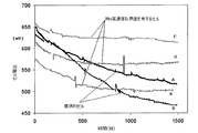
図1は、二つの標準的な(従来の)固体酸化物セルA及びB、並びに本発明の三つの固体酸化物セルC、D及びEの老化試験を示す。セル電圧は、運転時間の関数としての定電流で記録された。これらのセルは、強い分極(電流密度、i=0.75A/cm2)下の750℃の下に1500時間の試験の下で老化させた。 FIG. 1 shows an aging test of two standard (conventional) solid oxide cells A and B and three solid oxide cells C, D and E of the present invention. The cell voltage was recorded at a constant current as a function of operating time. These cells were aged under a 1500 hour test at 750 ° C. under strong polarization (current density, i = 0.75 A / cm 2 ).
本発明の三つの固体酸化物セルC、D及びEは、酸素電極層の堆積及び焼結後にマンガンで含浸されて、0.5〜5mgMn/cm2の範囲内の濃度を有していた。C、D及びEが、運転時間全体を通じてセル電圧が低下し続けるA及びBより
もずっと早くセル電圧に関して安定することがわかる。従って、本発明の固体酸化物セルの性能は、強い劣化を示す試験された標準的セルよりも良好な長期の耐久性を示す。
The three solid oxide cells C, D and E of the present invention were impregnated with manganese after deposition and sintering of the oxygen electrode layer and had a concentration in the range of 0.5-5 mg Mn / cm 2 . It can be seen that C, D and E stabilize with respect to the cell voltage much faster than A and B where the cell voltage continues to drop throughout the run time. Thus, the performance of the solid oxide cell of the present invention exhibits better long-term durability than a tested standard cell that exhibits strong degradation.
酸素電極層をMnで含浸することの有益な効果は、前述のLa−ジルコニウム酸塩及びSr−ジルコニウム酸塩、及びその他の分解生成物の形成を抑えることが推測可能であることである。標準的なセルに観察された強い分解がジルコニウム酸塩の形成に関連する可能性は、図2に再現された発見によって支持される。 The beneficial effect of impregnating the oxygen electrode layer with Mn is that it can be speculated to suppress the formation of the aforementioned La-zirconate and Sr-zirconate and other decomposition products. The possibility that the strong degradation observed in standard cells is related to zirconate formation is supported by the findings reproduced in FIG.
図2は、空気中又は窒素中での様々な加熱処理後のYSZ/LSM粉末混合物のX線回折図を示す。試料Fは、YSZ−LSM粉末混合物を、窒素中で1000℃に9週間曝した後に得られた結果を示し、一方、試料Gは、YSZ−LSM粉末混合物を、窒素中で1000℃に9週間曝した後、空気中で1000℃に4週間曝した後に得られた結果を示す。 FIG. 2 shows the X-ray diffractogram of the YSZ / LSM powder mixture after various heat treatments in air or nitrogen. Sample F shows the results obtained after exposing the YSZ-LSM powder mixture to 1000 ° C. in nitrogen for 9 weeks, while sample G shows the YSZ-LSM powder mixture in nitrogen at 1000 ° C. for 9 weeks. The results obtained after exposure to 1000 ° C. in air for 4 weeks are shown.
ここに、粉末反応性試験の結果が示されており、試料F及び試料Gの両方が、YSZについてのピーク(2θ≫30.1において)、及びLSMについてのピーク(2θ≫32.4、32.6において)を示すことがわかる。しかしながら、試料Fは、2θ≫30.9においてSrZrO3についての追加のピークを示している。同じピークはまた、試料Gについても観察された。しかしながら、これは4週間空気にさらされた後に消滅した。 Here are the results of the powder reactivity test, where both Sample F and Sample G have peaks for YSZ (at 2θ >> 30.1) and peaks for LSM (2θ >> 32.4, 32 .6). However, Sample F shows an additional peak for SrZrO 3 at 2θ >> 30.9. The same peak was also observed for sample G. However, it disappeared after being exposed to air for 4 weeks.
そのため、ジルコニウム酸塩の形成は、酸素分圧、pO2に強く依存することが示される。粉末混合物がN2中で加熱処理される場合に、ジルコニウム酸塩分解生成物が形成する。これは、粉末が引き続いて空気中で加熱処理される場合に消滅する。この発見は、分極の増加が酸素電極−粒子−電解質界面における、pO2の低減に相当するため、セルの分解速度が、分極の増加に伴って増加するという理由が、ジルコニウム酸塩の形成に関連するという作業仮説を支持する。酸素電極/電解質境界における酸素分圧、pO2が、空気の特徴に非常に近い低い電流密度(i=0.25A/cm2)において、分解は全く観察されない。 Therefore, it is shown that the formation of zirconate strongly depends on the oxygen partial pressure, pO 2 . When the powder mixture is heated in N 2, a zirconium salt decomposition products are formed. This disappears when the powder is subsequently heat treated in air. This finding is due to the fact that the increase in polarization corresponds to a decrease in pO 2 at the oxygen electrode-particle-electrolyte interface, and the reason that the cell degradation rate increases with increasing polarization is due to the formation of zirconate. Support the working hypothesis of being related. No decomposition is observed at low current densities (i = 0.25 A / cm 2 ) where the oxygen partial pressure at the oxygen electrode / electrolyte interface, pO 2, is very close to that of air.
超化学量論量のマンガンの添加は、分解の低減をもたらすことが知られている。しかしながら、この低減は、固体酸化物セルの運転が長期間又は高い分極で行われる場合には、長期間効果的ではない。 It is known that the addition of superstoichiometric amounts of manganese results in reduced decomposition. However, this reduction is not effective for a long time if the operation of the solid oxide cell is performed for a long time or with high polarization.
図3は、750℃、i=0.75A/cm2における1500時間の試験後の本発明のSOFCセルの電解質/酸素電極界面のSEM像を示す。界面の微小構造は、標準的SOFCセルとは大きく異なっている(図4を参照)。増加したMn含有量を有する層は、本発明のセルにおいてEDSによって観察されるが、標準的セルでは観察されない。本発明のセル中の酸素電極は、標準的なセルよりも良好に電解質に接着する。 FIG. 3 shows an SEM image of the electrolyte / oxygen electrode interface of the SOFC cell of the present invention after 1500 hours of testing at 750 ° C. and i = 0.75 A / cm 2 . The interface microstructure is very different from a standard SOFC cell (see FIG. 4). Layers with increased Mn content are observed by EDS in the cells of the invention, but not in standard cells. The oxygen electrode in the cell of the present invention adheres better to the electrolyte than the standard cell.
図4は、750℃、i=0.75A/cm2での1500時間の試験後の標準的なSOFCセルの電解質/酸素電極界面のSEM像を示している。 FIG. 4 shows an SEM image of the electrolyte / oxygen electrode interface of a standard SOFC cell after 1500 hours of testing at 750 ° C. and i = 0.75 A / cm 2 .
図5は、図3におけるのと同じセルの電解質/酸素電極界面のSEM像を拡大して示す。二次相が界面領域に見られる。 FIG. 5 shows an enlarged SEM image of the electrolyte / oxygen electrode interface of the same cell as in FIG. A secondary phase is seen in the interface region.
図6は、750℃、i=0.75A/cm2での1500時間の試験後の本発明のSOFCセルの、酸素電極を除去した後の電解質表面のSEM像を示す。図7に示す標準的なセルとは異なって、LSMクレーターのほとんどはナノ粒子を含まない。LSMクレーターに加えて、不規則な形状の多数のインプリントもまた存在する。これらは、Mn含浸により境界に導入された新たな相に起因し、そして酸素電極を電解質にしっかりと固定するのを助けるものと思われる。 FIG. 6 shows an SEM image of the electrolyte surface of the SOFC cell of the present invention after 1500 hours test at 750 ° C., i = 0.75 A / cm 2 after removing the oxygen electrode. Unlike the standard cell shown in FIG. 7, most of the LSM craters do not contain nanoparticles. In addition to LSM craters, there are also numerous imprints with irregular shapes. These are attributed to the new phase introduced at the boundary by Mn impregnation and are believed to help secure the oxygen electrode to the electrolyte.
図7は、750℃、i=0.75A/cm2での1500時間の試験後のセルの、酸素電極を除去した後の電解質表面のSEM像を示している。小型のLSMクレーターが、そのクレーターの縁におけるジルコニウム酸塩のナノ粒子と共に観察される。 FIG. 7 shows an SEM image of the electrolyte surface of the cell after 1500 hours of testing at 750 ° C. and i = 0.75 A / cm 2 after removing the oxygen electrode. Small LSM craters are observed with zirconate nanoparticles at the edge of the crater.
Claims (11)
− 安定化ジルコニアを含む電解質層を燃料電極層の上に堆積させて、燃料電極支持体、燃料電極及び電解質のアセンブリを提供する工程、
− 上記の燃料電極支持体、燃料電極及び電解質のアセンブリを一緒に焼結して、予備焼結されたハーフセルを提供する工程、
− 上記の予備焼結されたハーフセルの上記電解質層の上に一つ以上の酸素電極層を堆積させて、完全な固体酸化物セルを提供する工程であって、その一つ以上の酸素電極層の少なくとも一つがランタン−ストロンチウム−マンガナイト、及び安定化ジルコニアの複合体を含む、前記工程、
− 上記の一つ以上の酸素電極層を上記予備焼結されたハーフセルと一緒に焼結して、焼結された完全な固体酸化物セルを提供する工程、
− 上記の焼結された完全な固体酸化物セルの一つ以上の酸素電極層をマンガンで含浸して、マンガン含浸固体酸化物セルを提供する工程、
を含む方法によって得ることができる固体酸化物セルであって、
前記の一つ以上の酸素電極層の少なくとも一つが、ランタン−ストロンチウム−マンガナイト及び安定化ジルコニアの複合体を含み、そしてランタン−ストロンチウム−マンガナイトにおける、マンガンの、ランタン及びストロンチウムに対する原子比が1よりも大きく、そして、
前記の一つ以上の酸素電極層の少なくとも一つの表面上に、0.5〜5mg/cm2の濃度でマンガンが含浸される、上記の固体酸化物セル。 -Depositing a fuel electrode layer on the fuel electrode support layer;
Depositing an electrolyte layer comprising stabilized zirconia on the fuel electrode layer to provide a fuel electrode support, fuel electrode and electrolyte assembly;
- Fuel electrode support above SL, the assembly of fuel electrode and electrolyte by sintering together, provides a half cell which is pre-sintering process,
-Depositing one or more oxygen electrode layers on the electrolyte layer of the pre-sintered half-cell to provide a complete solid oxide cell, the one or more oxygen electrode layers Wherein at least one of the above comprises a lanthanum-strontium-manganite and stabilized zirconia complex,
-Sintering one or more oxygen electrode layers together with the pre-sintered half-cell to provide a sintered complete solid oxide cell;
-Impregnating one or more oxygen electrode layers of the sintered complete solid oxide cell with manganese to provide a manganese-impregnated solid oxide cell;
A solid oxide cell obtainable by a method comprising
At least one of the one or more oxygen electrode layers comprises a lanthanum-strontium-manganite and stabilized zirconia complex, and the atomic ratio of manganese to lanthanum and strontium in the lanthanum-strontium-manganite is 1 Bigger than and
The solid oxide cell as described above, wherein manganese is impregnated at a concentration of 0.5 to 5 mg / cm 2 on at least one surface of the one or more oxygen electrode layers.
Applications Claiming Priority (2)
| Application Number | Priority Date | Filing Date | Title |
|---|---|---|---|
| DKPA200801704 | 2008-12-03 | ||
| DKPA200801704 | 2008-12-03 |
Publications (3)
| Publication Number | Publication Date |
|---|---|
| JP2010177187A JP2010177187A (en) | 2010-08-12 |
| JP2010177187A5 JP2010177187A5 (en) | 2013-01-24 |
| JP5591526B2 true JP5591526B2 (en) | 2014-09-17 |
Family
ID=41698263
Family Applications (1)
| Application Number | Title | Priority Date | Filing Date |
|---|---|---|---|
| JP2009274262A Expired - Fee Related JP5591526B2 (en) | 2008-12-03 | 2009-12-02 | Solid oxide cell and solid oxide cell stack |
Country Status (10)
| Country | Link |
|---|---|
| US (1) | US8304128B2 (en) |
| EP (1) | EP2194597B1 (en) |
| JP (1) | JP5591526B2 (en) |
| KR (1) | KR20100063667A (en) |
| CN (1) | CN101752586B (en) |
| AU (1) | AU2009243474B2 (en) |
| CA (1) | CA2686846A1 (en) |
| DK (1) | DK2194597T3 (en) |
| ES (1) | ES2456821T3 (en) |
| RU (1) | RU2521874C2 (en) |
Families Citing this family (17)
| Publication number | Priority date | Publication date | Assignee | Title |
|---|---|---|---|---|
| WO2007145015A1 (en) * | 2006-06-16 | 2007-12-21 | Sharp Kabushiki Kaisha | Positive electrode, process for producing the same, and lithium secondary battery utilizing the positive electrode |
| KR101253956B1 (en) | 2010-12-28 | 2013-04-16 | 주식회사 포스코 | Method for manufacturing metal supported solid oxide fuel cell |
| US20130093129A1 (en) * | 2011-10-07 | 2013-04-18 | Aravind Mohanram | Method of forming a solid oxide fuel cell |
| JP5622754B2 (en) * | 2012-01-05 | 2014-11-12 | 三菱重工業株式会社 | Method for producing solid oxide fuel cell and solid oxide fuel cell |
| WO2014012673A1 (en) | 2012-07-19 | 2014-01-23 | Technical University Of Denmark | Solid oxide cell oxygen electrode with enhanced durability |
| KR20140131441A (en) * | 2013-05-03 | 2014-11-13 | 한국생산기술연구원 | Method for manufacturing solid electrolyte for solid oxide fuel cell and manufacturing method for unit cell of the solid oxide fuel cell |
| JP2015213050A (en) * | 2014-04-14 | 2015-11-26 | パナソニックIpマネジメント株式会社 | Solid oxide fuel battery and electrolysis device |
| CN104037425B (en) * | 2014-05-23 | 2016-07-20 | 景德镇陶瓷学院 | A kind of intermediate temperature SOFC flat board anode support type monocell anode construction and preparation method thereof |
| GB2524638B (en) * | 2015-02-06 | 2016-04-06 | Ceres Ip Co Ltd | Electrolyte forming process |
| KR102054537B1 (en) * | 2015-08-26 | 2019-12-10 | 주식회사 엘지화학 | Method for manufacturing solid oxide fuel cell, solid oxide fuel cell and battery module comprising the solid oxide fuel cell |
| DE112017005356T5 (en) | 2016-10-24 | 2019-07-11 | Precision Combustion, Inc. | Solid oxide cell with internal heating device |
| JP6290471B1 (en) * | 2017-02-16 | 2018-03-07 | 日本特殊陶業株式会社 | Electrochemical reaction cell and electrochemical reaction cell stack |
| KR102158619B1 (en) * | 2018-08-31 | 2020-09-25 | 대전대학교 산학협력단 | Soild-electrolyte membrane coated with oxide electrode for electrochemical oxygen generator and manufacturing method thereof |
| CN109768292B (en) * | 2019-03-15 | 2021-09-28 | 福州大学 | Method for preparing anode in situ by electrochemical polarization of solid oxide fuel cell |
| US11837766B2 (en) | 2020-11-09 | 2023-12-05 | Advanced Manufacturing LLC | System and method for continuous fabrication of graded structured units using additive manufacturing |
| CN112751041B (en) * | 2021-01-17 | 2021-12-03 | 大连理工大学 | Method for preparing NiO/apatite lanthanum silicate submicron-nano porous anode functional layer |
| EP4334503A1 (en) | 2021-05-06 | 2024-03-13 | Topsoe A/S | Interconnect for solid oxide cell (soc) |
Family Cites Families (16)
| Publication number | Priority date | Publication date | Assignee | Title |
|---|---|---|---|---|
| JPH03112057A (en) * | 1989-09-27 | 1991-05-13 | Osaka Gas Co Ltd | Solid electrolyte fuel cell |
| JPH05190183A (en) | 1992-01-13 | 1993-07-30 | Ngk Insulators Ltd | Solid electrolyte type fuel cell |
| DK171621B1 (en) * | 1993-03-01 | 1997-02-24 | Risoe Forskningscenter | Solid oxide fuel cell with cathode of LSM and YSZ |
| US5543239A (en) * | 1995-04-19 | 1996-08-06 | Electric Power Research Institute | Electrode design for solid state devices, fuel cells and sensors |
| US6682842B1 (en) | 1999-07-31 | 2004-01-27 | The Regents Of The University Of California | Composite electrode/electrolyte structure |
| RU2280297C2 (en) * | 2000-11-09 | 2006-07-20 | Трастиз Оф Дзе Юниверсити Оф Пенсильвания | Using sulfur-containing fuels for directly oxidizing fuel cells |
| KR100424194B1 (en) | 2001-11-01 | 2004-03-24 | 한국과학기술연구원 | Electrode part having microstructure of extended triple phase boundary by porous ion conductive ceria film coating and Method to manufacture the said electrode |
| US6958196B2 (en) | 2003-02-21 | 2005-10-25 | Trustees Of The University Of Pennsylvania | Porous electrode, solid oxide fuel cell, and method of producing the same |
| US7550217B2 (en) * | 2003-06-09 | 2009-06-23 | Saint-Gobain Ceramics & Plastics, Inc. | Stack supported solid oxide fuel cell |
| CA2569866C (en) * | 2004-06-10 | 2011-05-17 | Risoe National Laboratory | Solid oxide fuel cell |
| RU2403655C9 (en) | 2005-04-21 | 2011-04-20 | Члены Правления Университета Калифорнии | Parent material infiltration and coating process |
| JP2006344543A (en) * | 2005-06-10 | 2006-12-21 | Tokyo Electric Power Co Inc:The | Manufacturing method of cell for solid oxide fuel battery |
| JP5190183B2 (en) | 2006-06-09 | 2013-04-24 | 三井農林株式会社 | Floc occurrence inhibitor for tea beverage |
| EP1928049A1 (en) | 2006-11-23 | 2008-06-04 | Technical University of Denmark | Thin solid oxide cell |
| DK2378600T3 (en) * | 2006-11-23 | 2013-07-01 | Univ Denmark Tech Dtu | Process for the preparation of reversible solid oxide cells |
| KR100793155B1 (en) * | 2006-12-20 | 2008-01-10 | 주식회사 포스코 | Fabrication method for unit cell of solid oxide fuel cell |
-
2009
- 2009-11-23 DK DK09014539.2T patent/DK2194597T3/en active
- 2009-11-23 ES ES09014539.2T patent/ES2456821T3/en active Active
- 2009-11-23 EP EP09014539.2A patent/EP2194597B1/en not_active Not-in-force
- 2009-11-30 US US12/627,082 patent/US8304128B2/en not_active Expired - Fee Related
- 2009-12-02 JP JP2009274262A patent/JP5591526B2/en not_active Expired - Fee Related
- 2009-12-02 RU RU2009144531/07A patent/RU2521874C2/en not_active IP Right Cessation
- 2009-12-02 AU AU2009243474A patent/AU2009243474B2/en not_active Ceased
- 2009-12-02 CA CA2686846A patent/CA2686846A1/en not_active Abandoned
- 2009-12-02 KR KR1020090118487A patent/KR20100063667A/en not_active Application Discontinuation
- 2009-12-03 CN CN200910252698.5A patent/CN101752586B/en not_active Expired - Fee Related
Also Published As
| Publication number | Publication date |
|---|---|
| AU2009243474A1 (en) | 2010-06-17 |
| CN101752586A (en) | 2010-06-23 |
| US20100136380A1 (en) | 2010-06-03 |
| AU2009243474B2 (en) | 2011-06-02 |
| CA2686846A1 (en) | 2010-06-03 |
| JP2010177187A (en) | 2010-08-12 |
| KR20100063667A (en) | 2010-06-11 |
| US8304128B2 (en) | 2012-11-06 |
| EP2194597B1 (en) | 2014-03-05 |
| ES2456821T3 (en) | 2014-04-23 |
| EP2194597A1 (en) | 2010-06-09 |
| RU2009144531A (en) | 2011-06-10 |
| CN101752586B (en) | 2014-03-12 |
| DK2194597T3 (en) | 2014-06-16 |
| RU2521874C2 (en) | 2014-07-10 |
Similar Documents
| Publication | Publication Date | Title |
|---|---|---|
| JP5591526B2 (en) | Solid oxide cell and solid oxide cell stack | |
| JP5213589B2 (en) | Metal-supported solid oxide fuel cell | |
| Zhu et al. | A symmetrical solid oxide fuel cell prepared by dry-pressing and impregnating methods | |
| JP5430009B2 (en) | Removal of impurity phase from electrochemical devices | |
| JP5762295B2 (en) | New materials and structures for low temperature SOFC | |
| Yang et al. | Characterization of infiltrated (La0. 75Sr0. 25) 0.95 MnO3 as oxygen electrode for solid oxide electrolysis cells | |
| JP5167033B2 (en) | Electrodes based on ceria and strontium titanate | |
| US8518605B2 (en) | Ceramic material combination for an anode of a high-temperature fuel cell | |
| US20040166380A1 (en) | Porous electrode, solid oxide fuel cell, and method of producing the same | |
| Fan et al. | Infiltration of La0· 6Sr0· 4FeO3-δ nanoparticles into YSZ scaffold for solid oxide fuel cell and solid oxide electrolysis cell | |
| JP2005529464A (en) | Ceramic anode and method for producing the same | |
| JP2009110933A5 (en) | ||
| JP2009110934A5 (en) | ||
| JP2006351405A (en) | Sofc fuel electrode, and its manufacturing method | |
| KR20130047534A (en) | Solid oxide fuel cell and solid oxide electrolysis cell including ni-ysz fuel(hydrogen) electrode, and fabrication method thereof | |
| Yoo et al. | A Facile Combustion Synthesis Route for Performance Enhancement of La 0.6 Sr 0.4 Co 0.2 Fe 0.8 O 3-δ (LSCF6428) as a Robust Cathode Material for IT-SOFC | |
| JP5389378B2 (en) | Composite ceramic electrolyte structure, manufacturing method thereof and related article | |
| KR101534607B1 (en) | Porous cathode composite for solid oxide regenerative fuel cell, fabrication method thereof and solid oxide regenerative fuel cell comprising the same | |
| Gil et al. | Cathode-supported hybrid direct carbon fuel cells | |
| JP5550223B2 (en) | Ceramic electrolyte processing method and related products | |
| KR20200049068A (en) | SOFC cathodes using electrochemical technique and its manufacturing method | |
| JP7114555B2 (en) | Electrodes for water vapor electrolysis | |
| US20230420691A1 (en) | Method of manufacturing nanolayered cathodes for solid oxide fuel cell using ultrasonic spray infiltration and solid oxide fuel cell manufactured using same | |
| JP4577707B2 (en) | Electrochemical cell | |
| KR20240047293A (en) | Composition for buffer layer of solid oxide fuel cell and solid oxide fuel cell containing the same |
Legal Events
| Date | Code | Title | Description |
|---|---|---|---|
| RD04 | Notification of resignation of power of attorney |
Free format text: JAPANESE INTERMEDIATE CODE: A7424 Effective date: 20100604 |
|
| A521 | Written amendment |
Free format text: JAPANESE INTERMEDIATE CODE: A523 Effective date: 20121130 |
|
| A621 | Written request for application examination |
Free format text: JAPANESE INTERMEDIATE CODE: A621 Effective date: 20121130 |
|
| A977 | Report on retrieval |
Free format text: JAPANESE INTERMEDIATE CODE: A971007 Effective date: 20130717 |
|
| A131 | Notification of reasons for refusal |
Free format text: JAPANESE INTERMEDIATE CODE: A131 Effective date: 20130813 |
|
| A601 | Written request for extension of time |
Free format text: JAPANESE INTERMEDIATE CODE: A601 Effective date: 20131112 |
|
| A602 | Written permission of extension of time |
Free format text: JAPANESE INTERMEDIATE CODE: A602 Effective date: 20131115 |
|
| A521 | Written amendment |
Free format text: JAPANESE INTERMEDIATE CODE: A523 Effective date: 20140212 |
|
| A131 | Notification of reasons for refusal |
Free format text: JAPANESE INTERMEDIATE CODE: A131 Effective date: 20140318 |
|
| A521 | Written amendment |
Free format text: JAPANESE INTERMEDIATE CODE: A523 Effective date: 20140604 |
|
| TRDD | Decision of grant or rejection written | ||
| A01 | Written decision to grant a patent or to grant a registration (utility model) |
Free format text: JAPANESE INTERMEDIATE CODE: A01 Effective date: 20140702 |
|
| A61 | First payment of annual fees (during grant procedure) |
Free format text: JAPANESE INTERMEDIATE CODE: A61 Effective date: 20140730 |
|
| R150 | Certificate of patent or registration of utility model |
Ref document number: 5591526 Country of ref document: JP Free format text: JAPANESE INTERMEDIATE CODE: R150 |
|
| LAPS | Cancellation because of no payment of annual fees |