JP2005529464A - Ceramic anode and method for producing the same - Google Patents
Ceramic anode and method for producing the same Download PDFInfo
- Publication number
- JP2005529464A JP2005529464A JP2004512218A JP2004512218A JP2005529464A JP 2005529464 A JP2005529464 A JP 2005529464A JP 2004512218 A JP2004512218 A JP 2004512218A JP 2004512218 A JP2004512218 A JP 2004512218A JP 2005529464 A JP2005529464 A JP 2005529464A
- Authority
- JP
- Japan
- Prior art keywords
- anode
- ceramic material
- doped
- fuel cell
- ysz
- Prior art date
- Legal status (The legal status is an assumption and is not a legal conclusion. Google has not performed a legal analysis and makes no representation as to the accuracy of the status listed.)
- Pending
Links
Images


Classifications
-
- H—ELECTRICITY
- H01—ELECTRIC ELEMENTS
- H01M—PROCESSES OR MEANS, e.g. BATTERIES, FOR THE DIRECT CONVERSION OF CHEMICAL ENERGY INTO ELECTRICAL ENERGY
- H01M4/00—Electrodes
- H01M4/86—Inert electrodes with catalytic activity, e.g. for fuel cells
- H01M4/8647—Inert electrodes with catalytic activity, e.g. for fuel cells consisting of more than one material, e.g. consisting of composites
-
- H—ELECTRICITY
- H01—ELECTRIC ELEMENTS
- H01M—PROCESSES OR MEANS, e.g. BATTERIES, FOR THE DIRECT CONVERSION OF CHEMICAL ENERGY INTO ELECTRICAL ENERGY
- H01M4/00—Electrodes
- H01M4/86—Inert electrodes with catalytic activity, e.g. for fuel cells
-
- H—ELECTRICITY
- H01—ELECTRIC ELEMENTS
- H01M—PROCESSES OR MEANS, e.g. BATTERIES, FOR THE DIRECT CONVERSION OF CHEMICAL ENERGY INTO ELECTRICAL ENERGY
- H01M4/00—Electrodes
- H01M4/86—Inert electrodes with catalytic activity, e.g. for fuel cells
- H01M4/8605—Porous electrodes
- H01M4/8621—Porous electrodes containing only metallic or ceramic material, e.g. made by sintering or sputtering
-
- H—ELECTRICITY
- H01—ELECTRIC ELEMENTS
- H01M—PROCESSES OR MEANS, e.g. BATTERIES, FOR THE DIRECT CONVERSION OF CHEMICAL ENERGY INTO ELECTRICAL ENERGY
- H01M4/00—Electrodes
- H01M4/86—Inert electrodes with catalytic activity, e.g. for fuel cells
- H01M4/88—Processes of manufacture
-
- H—ELECTRICITY
- H01—ELECTRIC ELEMENTS
- H01M—PROCESSES OR MEANS, e.g. BATTERIES, FOR THE DIRECT CONVERSION OF CHEMICAL ENERGY INTO ELECTRICAL ENERGY
- H01M4/00—Electrodes
- H01M4/86—Inert electrodes with catalytic activity, e.g. for fuel cells
- H01M4/88—Processes of manufacture
- H01M4/8878—Treatment steps after deposition of the catalytic active composition or after shaping of the electrode being free-standing body
- H01M4/8882—Heat treatment, e.g. drying, baking
- H01M4/8885—Sintering or firing
-
- H—ELECTRICITY
- H01—ELECTRIC ELEMENTS
- H01M—PROCESSES OR MEANS, e.g. BATTERIES, FOR THE DIRECT CONVERSION OF CHEMICAL ENERGY INTO ELECTRICAL ENERGY
- H01M4/00—Electrodes
- H01M4/86—Inert electrodes with catalytic activity, e.g. for fuel cells
- H01M4/90—Selection of catalytic material
- H01M4/9016—Oxides, hydroxides or oxygenated metallic salts
- H01M4/9025—Oxides specially used in fuel cell operating at high temperature, e.g. SOFC
- H01M4/9033—Complex oxides, optionally doped, of the type M1MeO3, M1 being an alkaline earth metal or a rare earth, Me being a metal, e.g. perovskites
-
- Y—GENERAL TAGGING OF NEW TECHNOLOGICAL DEVELOPMENTS; GENERAL TAGGING OF CROSS-SECTIONAL TECHNOLOGIES SPANNING OVER SEVERAL SECTIONS OF THE IPC; TECHNICAL SUBJECTS COVERED BY FORMER USPC CROSS-REFERENCE ART COLLECTIONS [XRACs] AND DIGESTS
- Y02—TECHNOLOGIES OR APPLICATIONS FOR MITIGATION OR ADAPTATION AGAINST CLIMATE CHANGE
- Y02E—REDUCTION OF GREENHOUSE GAS [GHG] EMISSIONS, RELATED TO ENERGY GENERATION, TRANSMISSION OR DISTRIBUTION
- Y02E60/00—Enabling technologies; Technologies with a potential or indirect contribution to GHG emissions mitigation
- Y02E60/30—Hydrogen technology
- Y02E60/50—Fuel cells
Abstract
本発明は、一般に、固形酸化物燃料セル中での使用のためのセラミックアノードに関し、アノードは主にセラミック材料から構成される。The present invention relates generally to ceramic anodes for use in solid oxide fuel cells, where the anode is composed primarily of a ceramic material.
Description
1.発明の分野
本発明は、一般には、固形酸化物燃料セル(SOFC)及びそれらの製造方法に関する。特定すれば、本発明は、セラミックアノード及び当該セラミックアノードが伝導性金属、例えばNi,Fe及びCoに代わり電子工学的に伝導性の酸化物を含み、セラミックアノードサポート材料の孔により少なくとも一部が被覆される(deposited)。他の成分及び方法を使用することにより、燃料セルの電気伝導性及び燃料効率を改善することができる。
1. The present invention relates generally to solid oxide fuel cells (SOFCs) and methods for their production. In particular, the present invention relates to a ceramic anode and the ceramic anode comprising an electronically conductive oxide instead of a conductive metal such as Ni, Fe and Co, and at least in part by the pores of the ceramic anode support material. Deposited. By using other components and methods, the electrical conductivity and fuel efficiency of the fuel cell can be improved.
2.関連分野の記載
固形酸化物燃料セルは、実行可能な高温燃料セル技術としての認識において成長してきた。流体の電解質の使用に一般的に関連する金属腐食及び電解質の管理の問題を排除した流体の電解質は存在しない。むしろ、セルの電解質は主として固形酸化物燃料セルの操作の間に一般的に遭遇する高温環境を生き残ることができる固形セラミック材料から作成される。約600℃を超える操作温度は、内部のリフォームを可能にさせ、貴重ではない材料により速いキネティクスを促進し、そして廃熱発電のため又はボトミングサイクルにおける使用のための、高品質の副産物の熱を生じる。固形酸化物の高温は、しかしながら、その構成材料に対して厳格な要求をつきつける。慣用の固形酸化物燃料セルの高い操作温度のため(約600から1000℃)、各セルコンポーネントを構成するのに使用される材料は、酸化及び還元環境における化学安定性、接触する材料の化学安定性、伝導性及び熱化学適合性により制限される。
2. 2. Description of Related Art Solid oxide fuel cells have grown in recognition as a viable high temperature fuel cell technology. There are no fluid electrolytes that have eliminated the problems of metal corrosion and electrolyte management generally associated with the use of fluid electrolytes. Rather, the cell electrolyte is made primarily from solid ceramic materials that can survive the high temperature environments commonly encountered during operation of solid oxide fuel cells. Operating temperatures above about 600 ° C allow internal remodeling, promote faster kinetics for non-precious materials, and generate high quality by-product heat for waste heat power generation or for use in bottoming cycles. Arise. The high temperature of solid oxides, however, imposes strict requirements on its constituent materials. Due to the high operating temperature of conventional solid oxide fuel cells (approximately 600 to 1000 ° C.), the materials used to construct each cell component are chemically stable in oxidizing and reducing environments, and chemically stable in contacting materials. Limited by conductivity, conductivity and thermochemical compatibility.
固形酸化物熱セルのもっとも一般的なアノード材料はNiOの高温の焼成により製造されるニッケル(Ni)−サーメット及びイットリウム安定化ジルコニア(YSZ)粉末である。高温の焼成は、通常、YSZにおいて必要なイオン伝導性を得るのに必須であると考えられる。これらのNi−サーメットは水素(H2)燃料のためにうまく機能し、そしてアノードへの燃料(feed)の中に十分な水が存在すれば、炭化水素の内部蒸気リフォームを可能にさせる。Niは乾燥メタンの中でグラファイト繊維の形成を触媒するため、1より大きい蒸気/メタン比においてニッケルを使用して作成されたアノードを使用する必要がある。蒸気のリフォームの要求なしでの高濃度の炭化水素の直接の酸化は可能であり、とりわけ、米国特許出願公開番号20010029231及び20010053471に記載されている。 The most common anode materials for solid oxide heat cells are nickel (Ni) -cermet and yttrium stabilized zirconia (YSZ) powders produced by high temperature firing of NiO. High temperature firing is usually considered essential to obtain the necessary ionic conductivity in YSZ. These Ni-cermets work well for hydrogen (H 2 ) fuel, and allow sufficient internal steam reforming of the hydrocarbon if enough water is present in the fuel to the anode. Since Ni catalyzes the formation of graphite fibers in dry methane, it is necessary to use an anode made with nickel at a steam / methane ratio greater than 1. Direct oxidation of high concentrations of hydrocarbons without the need for steam reforming is possible and is described, inter alia, in US Patent Application Publication Nos. 20010029231 and 20010053471.
Niはグラファイトの形成を触媒して蒸気のリフォームを必要とすることが知られているため、そのような濃い蒸気/メタン比を必要としない幾つかのアノードが製造され、完全に異なる種類のアノードが製造され、ドープされたセリアに基づくか(Eguchi,K,et al.,Solid State Ionics,52,165(1992);Mogensen,G.,Journal of the Electrochemical Society,141,2122(1994);及びPutna,E.S.,et al.,Lamg,uir,11,4832(1995))、ペロブスカイトに基づくか(Baker,R.T.,et al.,Solid State Ionics,72,328(1994);Asano,K.,et al.,Journal of the Electrochemical Society,142,3241(1995);及びHiei,R.,et al.,Solid State Ionics,1267,86−88(1996))、LaCrO3及びSrTiO3に基づくか(Doshi,R.,et al.,J.Catal.140,557(1993);Sfeir,J.,et al.,J.Eur.Ceram.Cos.,19,897(1999);Weston,M.,et al.,Solid State Ionics,247,113−115(1998);及びLiu,J.,et al.,Electrochem.& Solid−State Lett.,5,A122(2002))、又は銅に基づくアノードに基づく(米国特許出願公開番号20010029231及び20010053471、それらの開示は引用によりそれらの全体を本明細書に編入する)。Co(Sammnes,N.M.,et al.,Journal of Materials Science,31,6060(1996))、Fe(Bartholomew,C.H.,CATALYSIS REVIEW−Scientific Engineering,24,67(1982)、Ag又はMn(Kawada,T.,et al.,Solid State Ionics,418,53−56,(1992))を含む他の金属をNiで置換することも考えられた。 Since Ni is known to catalyze the formation of graphite and require steam reforming, several anodes have been produced that do not require such a rich steam / methane ratio and are completely different types of anodes. Is based on doped and doped ceria (Eguchi, K, et al., Solid State Ionics, 52, 165 (1992); Mogensen, G., Journal of the Electrochemical Society, 141, 1222 (1994); Putna, ES, et al., Lamg, ir, 11, 4832 (1995)) or based on perovskites (Baker, RT, et al., Solid State Ionics, 72, 328 (1994); Asano, K , Et al, Journal of the Electrochemical Society, 142,3241 (1995);.. And Hiei, R., et al, Solid State Ionics, 1267,86-88 (1996)), or based on the LaCrO 3 and SrTiO 3 (Doshi, R., et al., J. Catal. 140, 557 (1993); Sfeir, J., et al., J. Eur. Ceram. Cos., 19, 897 (1999); , Et al., Solid State Ionics, 247, 113-115 (1998); and Liu, J., et al., Electrochem. & Solid-State Lett., 5, A122 (2002)), or copper based Based on the anode (US Patent Application Publication Nos. 20010029231 and 20010053471, the disclosures of which are incorporated herein by reference in their entirety). Co (Samnes, NM, et al., Journal of Materials Science, 31, 6060 (1996)), Fe (Bartholomew, CH, CATALYSIS REVIEW-Scientific Engineering, 24, 67, 198, or 287 (G). It was also considered that other metals including Mn (Kawada, T., et al., Solid State Ionics, 418, 53-56, (1992)) were replaced with Ni.
アノードにおいて使用できた様々な電子伝導体の触媒特性に基づいて、Cu−に基づくアノードがSOFCにおける使用のために開発された(S.Park,et al.,Nature,404,265(2000);R.J.Gorte,et al.,Adv.Materials,12,1465(2000);S.Park,et al.,J.Electrochem.Soc.,146,3603(1999);S.Park,et al.,J.Electrochem.Soc.,148,A443(2001);及びH.Kim,et al.,J.Am.Ceram.Soc.,85,1473(2002))。Niに比較して、CuはC−C結合の形成に触媒活性をもたない。その融点1083℃はNiの1453℃に比較すると低い;しかしながら、低温の操作(例えば、<800℃)のためには、Cuが十分に安定らしい。 Based on the catalytic properties of various electronic conductors that could be used in the anode, Cu-based anodes were developed for use in SOFC (S. Park, et al., Nature, 404, 265 (2000); R. J. Gorte, et al., Adv. Materials, 12, 1465 (2000); S. Park, et al., J. Electrochem. Soc., 146, 3603 (1999); J. Electrochem. Soc., 148, A443 (2001); and H. Kim, et al., J. Am. Ceram. Soc., 85, 1473 (2002)). Compared to Ni, Cu has no catalytic activity in the formation of C—C bonds. Its melting point of 1083 ° C. is low compared to 1453 ° C. of Ni; however, Cu seems to be sufficiently stable for low temperature operation (eg, <800 ° C.).
Cu2O及びCuOはYSZ電解質の稠密化(densification)に必要な温度より下の温度である、それぞれ1235℃及び1326℃において融解するため、Ni−YSZサーメットを生成する第1の工程として通常使用されるのと類似の方法、CuOとYSZの混合された粉末の高温焼成により、Cu−YSZサーメットを製造することができない。Cu−YSZサーメットの製造のための別法は、よって、孔性YSZマトリックスを最初に製造して次にCuと酸化触媒を次の加工工程において添加することが開発された(R.J.Gorte,et al.,Adv.Materials,12,1465(2000);S.Park,et al.,J.Electrochem.Soc.,148,A443(2001))。最終的なサーメット中のCu相は高度に連結してなければならないので、高金属負荷が必要であり;そしてそのときでさえ、アノード構造中の全てのCu粒子間の伝導性は保証されない。 Since Cu 2 O and CuO melt at 1235 ° C. and 1326 ° C., respectively, below the temperature required for densification of the YSZ electrolyte, they are typically used as the first step to produce Ni-YSZ cermets. Cu-YSZ cermets cannot be produced by a similar process, high temperature firing of mixed powders of CuO and YSZ. An alternative method for the production of Cu-YSZ cermets has thus been developed, where a porous YSZ matrix is first produced and then Cu and an oxidation catalyst are added in the next processing step (RJ Gorte , Et al., Adv. Materials, 12, 1465 (2000); S. Park, et al., J. Electrochem. Soc., 148, A443 (2001)). Since the Cu phase in the final cermet must be highly connected, a high metal load is required; and even then, conductivity between all Cu particles in the anode structure is not guaranteed.
固形酸化物燃料セルのアノード中で使用される伝導性材料の幾つかの報告された欠点のため、誰かが電子伝導性酸化物、例えばLaCrO3及びSrTiO3の使用を提案した。これらの酸化物は、Ni,Fe及びCoが触媒する様式にてグラファイトの形成を触媒せず、そして結果的に電子伝導性セラミック酸化物がアノード中のこれらの材料の適切な代替物として考えられた。Doshi,R.,et al.,J.Catal.,140,557(1993);Sfeir,J.,et al.,J.Eur.Ceram.Cos.,19,897(1999);Weston,M.,et al.,Solid State Ionics,247,113−115(1998);及びLiu,J.,et al.,Electrochem & Solid−State Lett.,5,A122(2002)。 Because of some reported shortcomings of conductive materials used in the anodes of solid oxide fuel cells, someone has suggested the use of electronically conductive oxides such as LaCrO 3 and SrTiO 3 . These oxides do not catalyze the formation of graphite in a manner catalyzed by Ni, Fe and Co, and consequently electronically conductive ceramic oxides are considered suitable substitutes for these materials in the anode. It was. Doshi, R .; , Et al. , J .; Catal. , 140, 557 (1993); , Et al. , J .; Eur. Ceram. Cos. , 19, 897 (1999); Weston, M .; , Et al. , Solid State Ionics, 247, 113-115 (1998); and Liu, J. et al. , Et al. Electrochem & Solid-State Lett. , 5, A122 (2002).
アノード中のこれらの種類のセラミックを使用することに付随する問題は、それらの合成が難しいことである。一般に、伝導性酸化物から作成される電極は、電解質として使用される材料と一緒のコンポジットの形態である。例えば、電解質がYSZなら、電極はYSZと伝導性酸化物の粉末を混合し、そしてそれらをYSZの稠密な層(例えば、電解質層)に付着させることにより形成されるはずである。電子伝導性酸化物及びYSZの混合物を、次に、YSZが焼結することを可能にするのに十分な温度にて焼成することにより、電解質中のYSZと電極中のYSZとの間の密接な結合を形成させる。この合成は少なくとも2つの理由により問題を含み得る。 The problem with using these types of ceramics in the anode is that they are difficult to synthesize. In general, electrodes made from conductive oxides are in the form of composites with materials used as electrolytes. For example, if the electrolyte is YSZ, the electrode should be formed by mixing YSZ and a conductive oxide powder and depositing them on a dense layer of YSZ (eg, an electrolyte layer). The mixture of the electron conductive oxide and YSZ is then calcined at a temperature sufficient to allow the YSZ to sinter, thereby providing a close contact between the YSZ in the electrolyte and the YSZ in the electrode. To form a strong bond. This synthesis can be problematic for at least two reasons.
第1に、LaとSrは高温焼結後に反応してLa2Zr2O7及びSrZrO3を形成し得る。例えば、Hirschenhofer,D.B.,et al.,”Fue Cells A Handbook (Revision 3)”,U.S.DOE,pp.5−12(1994)を参照。これら特定の材料は自然界で有害であり、SOFCの性能に有害である。第2に、電子伝導性セラミック酸化物の熱膨張係数(CTE)は、電解質として使用されるセラミック酸化物のCTEと類似か又は同じであらねばならない。電極中の酸化物のCTE間に不適合が存在するなら、電極はコンポジットの加熱及び冷却の間に誘導されるストレスのために不安定になる。CTEsのこの適合は、通常、電子伝導性酸化物の修飾を必要とし、例えばSr及びMnのLaCrO3への添加による。例えば、Liu,et al.,Electrochem.& Solid−State Lett.,5,A122(2002)を参照。この修飾は、貧困な電子特性及び触媒特性を有する材料を導くかもしれない。 First, La and Sr can react after high temperature sintering to form La 2 Zr 2 O 7 and SrZrO 3 . For example, Hirschenhofer, D.M. B. , Et al. , “Fue Cells A Handbook (Revision 3)”, U.S. Pat. S. DOE, pp. 5-12 (1994). These specific materials are harmful in nature and are detrimental to SOFC performance. Second, the coefficient of thermal expansion (CTE) of the electronically conductive ceramic oxide must be similar or the same as the CTE of the ceramic oxide used as the electrolyte. If there is a mismatch between the CTE of oxides in the electrode, the electrode becomes unstable due to stress induced during heating and cooling of the composite. This adaptation of CTEs usually requires modification of the electron conducting oxide, for example by addition of Sr and Mn to LaCrO 3 . For example, Liu, et al. Electrochem. & Solid-State Lett. 5, A122 (2002). This modification may lead to materials with poor electronic and catalytic properties.
他の刊行物において開示された様々な特性、態様、方法及び装置の利点及び欠点の本明細書における記載は、本発明を限定することを如何なる意味においても意図しない。事実、発明の特定の特徴は、本明細書にて開示された特徴、態様、方法及び装置の幾つか又は全てをなおも保持しながら、特定の欠点を克服することができるかもしれない。 The descriptions herein of advantages and disadvantages of various features, aspects, methods and apparatus disclosed in other publications are not intended to limit the invention in any way. Indeed, certain features of the invention may be able to overcome certain shortcomings while still retaining some or all of the features, aspects, methods and apparatus disclosed herein.
発明の概要
高い燃料効率、電子伝導性、高出力を有し、そして炭化水素を直接酸化できる固形酸化物燃料セルを提供することが望まれる。アノード材料、及び固形酸化物燃料セル中での使用のためのアノード材料を製造する方法を提供することも望まれ、それにより当該材料が炭化水素の直接の酸化を可能にし、そして低温において作成され得る。発明の態様の特徴は、よって、高燃料効率、電子伝導性、高出力を有し、そして炭化水素並びにアノード材料を直接酸化できる固形酸化物燃料セル、当該アノード材料を作成する方法、及び当該固形酸化物燃料セルを製造する方法を提供することである。
SUMMARY OF THE INVENTION It is desirable to provide a solid oxide fuel cell that has high fuel efficiency, electronic conductivity, high power, and can directly oxidize hydrocarbons. It would also be desirable to provide an anode material, and a method for producing an anode material for use in a solid oxide fuel cell, thereby allowing the material to be directly oxidized and made at low temperatures. obtain. Features of embodiments of the invention are therefore solid oxide fuel cells having high fuel efficiency, electronic conductivity, high power and capable of directly oxidizing hydrocarbons and anode materials, methods of making the anode materials, and the solids A method of manufacturing an oxide fuel cell is provided.
本発明の様々な態様のこれらの特徴及び他の特徴に従うと、第1のセラミック材料を含む孔性セラミックマトリックス、及び上記孔性セラミックマトリックスの孔中に少なくとも一部被覆された(deposited)第2のセラミック材料からなる電子伝導性セラミック材料を含むアノードが提供される。当該アノードは電子伝導性材料を実質上含まないことが好ましい。 In accordance with these and other features of various aspects of the present invention, a porous ceramic matrix comprising a first ceramic material and a second at least partially deposited in the pores of the porous ceramic matrix. An anode comprising an electronically conductive ceramic material comprising the following ceramic materials is provided. The anode is preferably substantially free of electron conductive material.
発明の態様の追加の特徴によれば、第1のセラミック材料から孔性マトリックスを形成させ、第2のセラミック材料からなる電子伝導性セラミック材料を上記孔性マトリックスに添加し、そしてその結果の孔性構造を加熱してアノードを形成させることを含む、アノードの作成方法が提供される。 According to an additional feature of the inventive aspects, a porous matrix is formed from a first ceramic material, an electronically conductive ceramic material comprising a second ceramic material is added to the porous matrix, and the resulting pores A method of making an anode is provided that includes heating the sexual structure to form an anode.
発明の態様の別の特徴によれば、固形電解質、カソード材料、及び第1のセラミック材料を含む孔性セラミックマトリックス、及び上記孔性セラミックマトリックスの孔の中に少なくとも一部被覆された第2のセラミック材料からなる電子伝導性セラミック材料を含むアノードが提供される。 According to another feature of an aspect of the invention, a porous ceramic matrix comprising a solid electrolyte, a cathode material, and a first ceramic material, and a second coated at least partially within the pores of the porous ceramic matrix. An anode is provided that includes an electronically conductive ceramic material comprised of a ceramic material.
発明の態様のまた別の特徴によれば、固形酸化物燃料セルを作成する方法が提供され、第1セル材料からなり且つ少なくとも2つの向かい合った表面を有する孔性セラミックマトリックス材料を形成させ、表面のうちの一つをカソード材料に接触させ、そして反対の表面をアノード材料に接触させることを含む。アノード材料は、第2セラミック材料からなる電子伝導性セラミック材料を含む。そうして形成されたアノード材料は、接触後に、加熱されて、アノードを形成する。好ましい態様のこれら及び他の特徴及び利点は、好ましい態様の以下の詳細な説明を読んだ際に、より容易に明らかになる。 According to yet another aspect of the invention, there is provided a method of making a solid oxide fuel cell comprising forming a porous ceramic matrix material comprising a first cell material and having at least two opposing surfaces. One of them in contact with the cathode material and the opposite surface in contact with the anode material. The anode material includes an electron conductive ceramic material made of a second ceramic material. The anode material so formed is heated after contact to form the anode. These and other features and advantages of the preferred embodiments will become more readily apparent upon reading the following detailed description of the preferred embodiments.
好ましい態様の詳細な説明
本明細書にて使用される用語は、特定の態様を記載するためのものであり、そして本発明の範囲を限定することを意図しない。この開示を通して使用される単数形態「a」、「an」及び「the」は、他に文脈が明確に示さない限り、複数の言及を含む。即ち、例えば、「a solid oxide fuel cell」に対する言及は、積み重ねの中の多数のそのような燃料セル、並びに単一のセルを含み、そして「an anode」に対する言及は、一つ又はそれより多いアノード及び当業者に知られている均等物等などに対する言及である。
DETAILED DESCRIPTION OF THE PREFERRED EMBODIMENTS The terms used herein are for describing particular embodiments and are not intended to limit the scope of the invention. As used throughout this disclosure, the singular forms “a”, “an”, and “the” include plural references unless the context clearly indicates otherwise. Thus, for example, a reference to “a solid oxide fuel cell” includes a number of such fuel cells in the stack, as well as a single cell, and a reference to “an anode” is one or more. A reference to the anode and equivalents known to those skilled in the art.
表現「実質上金属がない(substantially no metal)」は、アノードが約5重量%未満の伝導性金属しか含まず、好ましくは約1重量%未満しか含まず、そしてもっとも好ましくは金属を含まないことを意味する。金属なしは、金属がアノードに添加されないことを意味するが、いくらかの金属は不純物として存在してよい。 The expression “substantially no metal” means that the anode contains less than about 5% by weight of conductive metal, preferably less than about 1% by weight, and most preferably no metal. Means. No metal means that no metal is added to the anode, but some metal may be present as an impurity.
別に定義しない限り、本明細書にて使用される全ての技術用語及び科学用語は、この発明が属する分野の当業者により普通に理解されるのと同じ意味を有する。本明細書にて記載されたのと類似又は均等なあらゆる方法及び材料が本発明の実施又は試験において使用できるが、好ましい方法、装置及び材料が今記載される。本明細書にて言及された全ての刊行物は、刊行物において報告されており、且つ本発明に関連して使用されるかもしれない様々なアノード、電解質、カソード、及び他の燃料セル成分を記載し且つ開示するために引用される。従来の発明によりそのような開示を予期する権利を本発明が与えられたという承認として解釈されることは、本明細書に何もない。 Unless defined otherwise, all technical and scientific terms used herein have the same meaning as commonly understood by one of ordinary skill in the art to which this invention belongs. Although any methods and materials similar or equivalent to those described herein can be used in the practice or testing of the present invention, the preferred methods, devices, and materials are now described. All publications mentioned in this specification contain various anode, electrolyte, cathode, and other fuel cell components that are reported in the publication and that may be used in connection with the present invention. Cited for description and disclosure. Nothing in this specification should be construed as an admission that the invention has been entitled to such disclosure by virtue of prior invention.
一般に、SOFCは、空気電極(カソード)、燃料電極(アノード)、及びこれらの2つの電極間に被覆された固形酸化物電解質から構成される。SOFC中で、電解質は固形形態にある。一般に、当該電解質は非金属セラミック、例えば稠密なイットリウム安定化ジルコニア(YSZ)セラミックから作成され、電子の非伝導体であり、有用な仕事を行うための外部回路を通して電子が通過するに違いないということを保証する。そうして、電解質は電解質の反対側で電位差の蓄積(buildup)を提供し、他方から燃料及びオキシダントガスを単離する。アノードとカソードは一般に孔性であり、カソードはしばしばドープされた亜マンガン酸ランタンから作成される。固形の酸化物燃料セルにおいて、水素又は炭化水素は燃料として一般に使用され、そして酸素又は空気はオキシダントとして使用される。 In general, a SOFC is composed of an air electrode (cathode), a fuel electrode (anode), and a solid oxide electrolyte coated between these two electrodes. In SOFC, the electrolyte is in a solid form. In general, the electrolyte is made from a non-metallic ceramic, such as a dense yttrium stabilized zirconia (YSZ) ceramic, is an electronic non-conductor and must pass electrons through an external circuit to do useful work. Guarantee that. Thus, the electrolyte provides a potential buildup on the other side of the electrolyte and isolates fuel and oxidant gas from the other. The anode and cathode are generally porous and the cathode is often made from doped lanthanum manganite. In solid oxide fuel cells, hydrogen or hydrocarbons are commonly used as fuel and oxygen or air is used as oxidant.
本発明のSOFCは、当業界において開示された技術を使用して作成されたあらゆる固形電解質及びあらゆるカソードを含み得る。本発明は、電解質又はカソードのために使用される如何なる特定の材料にも限定されないし、それら各々の製造方法にも特に限定されない。 The SOFC of the present invention can include any solid electrolyte and any cathode made using techniques disclosed in the art. The present invention is not limited to any particular material used for the electrolyte or cathode and is not particularly limited to their respective manufacturing methods.
類似の様式において、発明は、SOFCの如何なるデザインにも特に限定されない。固形酸化物燃料セルの幾つかの異なるデザインが開発されており、例えば、サポートされた管状デザイン、セグメント化されたセル直列デザイン、モノリシックデザイン、及びフラットプレートデザインを含む。これらのデザインの全ては文献に記載されており、例えばMinh,”High−Tenperature Fuel Cells Part 2:The Solid Oxide Cell,”Chemtech,21:120−126(1991)に記載されているデザインを含む。 In a similar manner, the invention is not particularly limited to any design of SOFC. Several different designs of solid oxide fuel cells have been developed, including, for example, supported tubular designs, segmented cell series designs, monolithic designs, and flat plate designs. All of these designs are described in the literature, including, for example, the design described in Minh, “High-Temperature Fuel Cells Part 2: The Solid Oxide Cell,” Chemtech, 21: 120-126 (1991).
管状デザインは、通常、電極及び電解質の層により外側をコートされた閉塞末端孔性ジルコニア管を含む。このデザインの性能は孔性の管にオキシダントを拡散させる要求により、いくらか制限される。ウエスチングハウスは、ジルコニア電解質膜を有する孔性ジルコニア又は亜マンガン酸ランタンストロンチウムのカソード管及びジルコニア電解質の厚さを貫通するクロム酸ランタンの内部連絡を有する燃料セル要素を記載する多数の米国特許を有する。アノードが電解質上にコートされることにより、役立つ(working)燃料セル3層を形成し、孔性ジルコニア支持体上の、不可欠な(integral)孔性カソード支持体又は孔性カソードの先端に、電解質膜を含む。セグメント化されたデザインが1960年代初期に提案され(Minh et al.,Science and Technology of Ceramic Fuel Cells,Elsvier,p.255(1995))、支持体上の薄いバンド状構造に被覆されたセル又は鐘と栓(bell−and−spigot)デザインにおけるような自己支持構造としてのセルからなる。 Tubular designs typically include closed end porous zirconia tubes that are externally coated with an electrode and electrolyte layer. The performance of this design is somewhat limited by the requirement to diffuse the oxidant into the porous tube. Westinghouse has published a number of U.S. patents describing porous zirconia or lanthanum strontium manganite cathode tubes with zirconia electrolyte membranes and fuel cell elements having lanthanum chromate interconnects through the thickness of the zirconia electrolyte. Have. The anode is coated on the electrolyte to form a working fuel cell trilayer and the electrolyte on the integral porous cathode support or porous cathode tip on the porous zirconia support. Including membrane. A segmented design was proposed in the early 1960s (Minh et al., Science and Technology of Ceramic Fuel Cells, Elsvier, p. 255 (1995)), or a cell covered with a thin band-like structure on a support or It consists of a cell as a self-supporting structure as in a bell-and-spigot design.
電解質膜をそれ自体の自立構造で立っていることを利用した平坦デザインは記載されている。セルは、一般に、単一の電極を電解質シートの各側面に適用することにより電極−電解質−電極積層品を提供する。一般に、これらの単一のセルは、次に、連続して積み重ねて接続することにより電位差をつくる。モノリシックデザインは、複数セル化されるか又は「ハニカム」タイプの構造を特徴的に有し、高いセル密度及び高い酸素伝導性の利点を提供する。当該セルは、様々な電極、伝導性内部連絡及び電解質層を組込んだ波形シート及び平板シートの、ガスデリバリーチャンネルのための1−2mmの一般的なセル間隔での組み合わせにより定義される。 A flat design utilizing the standing of the electrolyte membrane in its own free-standing structure has been described. The cell generally provides an electrode-electrolyte-electrode stack by applying a single electrode to each side of the electrolyte sheet. In general, these single cells then create a potential difference by stacking and connecting in succession. The monolithic design features a multi-celled or “honeycomb” type structure, providing the advantages of high cell density and high oxygen conductivity. The cell is defined by a combination of corrugated and flat sheets incorporating various electrodes, conductive interconnects and electrolyte layers, with a typical cell spacing of 1-2 mm for gas delivery channels.
米国特許第5,273,837号は、熱ショック耐性燃料セルのための薄いシート形態の、焼結電解質組成物を記載する。従順な電解質構造を作成するための方法は、粉末化セラミック及びバインダーを含む前駆体シートを予め焼結することにより薄くて柔軟な焼結ポリ結晶性電解質シートを提供することを含む。燃料セル回路の付加的成分を、米国特許第5,089,455号にも記載されたようなシートに直接結合させた金属、セラミック、又はサーメット電流伝導体を含む、その予め焼結されたシートに結合させる。米国特許第5,273,837号は、電解質の隣接のシートのカソードとアノードが互いに面するような、そして燃料セル集合体のホットゾーンにおいてセルが薄い内部連絡/分離体と連絡しないようなデザインを記載する。これらの薄い柔軟な焼結電解質−含有装置は、薄い電解質を通してのオーム損失の低さ並びに焼結状態におけるそれらの柔軟性及び強靭性のために、優れている。 US Pat. No. 5,273,837 describes a sintered electrolyte composition in the form of a thin sheet for a heat shock resistant fuel cell. A method for making a compliant electrolyte structure includes providing a thin and flexible sintered polycrystalline electrolyte sheet by pre-sintering a precursor sheet comprising a powdered ceramic and a binder. A pre-sintered sheet comprising a metal, ceramic, or cermet current conductor in which additional components of the fuel cell circuit are directly bonded to the sheet as described in US Pat. No. 5,089,455 To join. US Pat. No. 5,273,837 is designed such that the cathode and anode of adjacent sheets of electrolyte face each other and the cells do not communicate with the thin interconnect / separator in the hot zone of the fuel cell assembly. Is described. These thin flexible sintered electrolyte-containing devices are superior because of their low ohmic loss through the thin electrolyte and their flexibility and toughness in the sintered state.
電気化学セルの構築の別のアプローチは米国特許第5,190,834号、Kendallに記載されている。その特許の中の電極−電解質集合体は、電解質材料の平行なバンドに結合した内部連絡材料の平行な条痕(striations)又はストリップから形成されたコンポジット電解質膜の上に被覆された電極を含む。イットリウム安定化電解質に結合させたコバルト酸ランタン又は亜クロム酸ランタンの内部連絡が示唆されている。本発明のSOFCが上記の何れかの技術を使用して製造されることにより、所望のデザインを提供し、管状セルにも拘わらず、モノリシックセル、平坦なプレートセル等を提供してよい。本明細書において提供されるガイドラインを使用して、当業者は、あらゆる所望のデザイン配置を有する本発明のアノードを含むSOFCを作成することができる。 Another approach for the construction of electrochemical cells is described in US Pat. No. 5,190,834, Kendall. The electrode-electrolyte assembly in that patent includes an electrode coated on a composite electrolyte membrane formed from parallel striations or strips of interconnect material bonded to parallel bands of electrolyte material. . Internal communication of lanthanum cobaltate or lanthanum chromite bound to an yttrium-stabilized electrolyte is suggested. The SOFC of the present invention may be manufactured using any of the techniques described above to provide the desired design and provide monolithic cells, flat plate cells, etc., despite the tubular cells. Using the guidelines provided herein, one of ordinary skill in the art can make SOFCs that include the anode of the present invention having any desired design configuration.
本発明は、好ましくは、アノード、アノード作成方法、アノードを含む固形酸化物燃料セルを含む。本発明のアノードは、第1のセラミック材料からなる孔性セラミックマトリックス、及び当該セラミックマトリックスの孔内の少なくとも一部に被覆された第2のセラミック材料からなる電子伝導性セラミック材料を含む。実質上電子伝導性のない金属を上記アノードにおいて用いることが好ましい。 The present invention preferably includes an anode, a method of making the anode, and a solid oxide fuel cell including the anode. The anode of the present invention includes a porous ceramic matrix made of a first ceramic material, and an electron conductive ceramic material made of a second ceramic material coated on at least a part of the pores of the ceramic matrix. It is preferred to use a metal with substantially no electron conductivity in the anode.
本発明のアノード材料は、安定化されたYSZ又は第2のセラミック材料を含浸された他の電解質材料からなるのが好ましい。本発明における使用のための好ましい第2のセラミック材料は、限定ではないが、ドープされたセリア、例えばGd又はSm−をドープされたセリア、LaCrO3,SrTiO3,Y−ドープされたSrTiO3,Sr−ドープされたLaCrO3,(LSC),タングステンカーバイド(WC)、及びそれらの混合物を含む。孔性YSZと共に上記アノードに製剤化される(formulated)場合に、第2のセラミック材料LSCは、式La0.7Sr0.3CrO3−δ/YSZを有することが好ましい。本発明はこれらの特定のセラミック材料に限定されないこと、及び他のセラミック材料を上記アノード中で単独又は前記のセラミック材料と共に使用してよいことが、認識される。さらに、安定化されたYSZ以外の材料を第1セラミック材料として使用してよく、Gc−及びSm−ドープされたセリア(10から100重量%),Sc−ドープされたZrO2(100重量%まで)、ドープされたLaGaMnOx、及び他の電解質材料を含む。 The anode material of the present invention preferably comprises a stabilized YSZ or other electrolyte material impregnated with a second ceramic material. Preferred second ceramic materials for use in the present invention include, but are not limited to, doped ceria, such as Gd or Sm-doped ceria, LaCrO 3 , SrTiO 3 , Y-doped SrTiO 3 , Sr-doped LaCrO 3 , (LSC), tungsten carbide (WC), and mixtures thereof. When formulated into the anode with porous YSZ, the second ceramic material LSC preferably has the formula La 0.7 Sr 0.3 CrO 3-δ / YSZ. It will be appreciated that the invention is not limited to these particular ceramic materials and that other ceramic materials may be used alone or with the ceramic materials in the anode. Furthermore, better use of materials other than the stabilized YSZ as the first ceramic material, until Gc- and Sm- doped ceria (10 to 100% by weight), ZrO 2 (100 wt% which is Sc- doped ), Doped LaGaMnO x , and other electrolyte materials.
発明の一つの好ましい態様において、SOFCのアノードは、炭化水素へアノードを暴露することにより形成される炭素様被覆物も含む。好ましくは、アノードを、1より多い炭素原子を有する炭化水素に、より好ましくはブタンに暴露する。アノード材料は、好ましくは、炭化水素へ、約500から約900℃の範囲内、より好ましくは約600から約800℃の範囲内、そしてもっとも好ましくは約700℃の温度において暴露される。炭化水素への暴露は、概して、約1分から24時間、好ましくは約5分から約3時間、そしてもっとも好ましくは約10分から約1時間30分、続けることができる。アノード材料は、一度又は数回、炭化水素へ暴露することができる。
In one preferred embodiment of the invention, the SOFC anode also includes a carbon-like coating formed by exposing the anode to a hydrocarbon. Preferably the anode is exposed to a hydrocarbon having more than one carbon atom, more preferably to butane. The anode material is preferably exposed to the hydrocarbon at a temperature in the range of about 500 to about 900 ° C, more preferably in the range of about 600 to about 800 ° C, and most preferably about 700 ° C. Hydrocarbon exposure can generally continue for about 1 minute to 24 hours, preferably about 5 minutes to about 3 hours, and most preferably about 10 minutes to about 1
本発明者らは、驚くことに、アノード上に形成された炭素の量が平衡に達し、そして結果として形成された炭素が完全にアノードをコートしないことによりそれの効果を失わせることを発見した。あらゆる理論に拘束されることを意図しないが、本発明者らは、マイナーな量の炭化水素残基がアノードの表面上に被覆されて、伝導性酸化物がアノード組成物内に含まれた場合に、電子伝導粒子の間の隙間を埋めると信じる。1より多い炭素を有する炭化水素、例えばブタンによる処理後に、形成された炭化水素残基が隙間を埋めて伝導性を改善することにより、アノード表面からの電子の伝導性粒子への流れを可能にさせる。 The inventors have surprisingly discovered that the amount of carbon formed on the anode reaches equilibrium and that the resulting carbon loses its effect by not completely coating the anode. . While not intending to be bound by any theory, we have found that when a minor amount of hydrocarbon residues is coated on the surface of the anode and a conductive oxide is included in the anode composition. In addition, it is believed to fill the gaps between the electron conducting particles. After treatment with hydrocarbons having more than one carbon, such as butane, the hydrocarbon residues formed fill the gaps and improve conductivity, allowing electrons to flow from the anode surface to the conductive particles Let
電極上に任意に形成することができる炭素様被覆物は、好ましくは、多環芳香族化合物、より好ましくは概して互いに融合された2から6の環を含む融合されたベンゼン環である。これらの多環芳香族化合物は、アノード中でNi,Co,及びFeを使用する時に一般に形成されるグラファイト炭素繊維とは異なる(Toebes,M.L.,et al.,Catalysis Today,2002)。多環芳香族化合物は700℃において低いが限定された蒸気圧を有する。 The carbon-like coating that can optionally be formed on the electrode is preferably a polycyclic aromatic compound, more preferably a fused benzene ring containing from 2 to 6 rings fused together. These polycyclic aromatic compounds are different from graphite carbon fibers commonly formed when using Ni, Co, and Fe in the anode (Toebes, ML, et al., Catalysis Today, 2002). Polycyclic aromatic compounds have a low but limited vapor pressure at 700 ° C.
ほんの少量の炭素様残基は、明らかに伝導性を実質上増加させるのに十分である。本発明者らは、残基の化学形態が何であるかもしれないことを正確には知らないが、性能を顕著に増強させるために必要な量は、電極の全重量の、約10重量%未満、好ましくは約5重量%未満、そしてもっとも好ましくは約2重量%未満に相当するらしい。残基の密度が約1g/cm3、炭化水素に関して典型的な値、と見積もられたら、この残基の体積のフラクションは電極の全重量の5%未満である。残基の密度がグラファイトの密度により近いと見積もられたら、当該残基により占められる体積はさらに低くなるはずである。 Only a small amount of carbon-like residues is clearly sufficient to substantially increase conductivity. We do not know exactly what the chemical form of the residue may be, but the amount needed to significantly enhance performance is less than about 10% by weight of the total weight of the electrode. Preferably less than about 5% by weight, and most preferably less than about 2% by weight. If the residue density is estimated to be about 1 g / cm 3 , a typical value for hydrocarbons, the volume fraction of this residue is less than 5% of the total weight of the electrode. If the density of a residue is estimated closer to that of graphite, the volume occupied by that residue should be even lower.
炭素様被覆を形成するために電極を炭化水素で処理することの別の利点は、より低い量のイオン又は電子伝導性材料しか必要としないことである。比較すると、金属含有サーメットのアノード及びカソードのための最小金属含有率は約30体積%であると報告されている(Dees,D.W.,et al.,J.Electrochem.Soc.,134,2141(1987))。発明の様々な態様の一つの特徴は、実質上金属を含有しないで直接の酸化燃料セルを操作して(例えば、約5重量%未満の金属から金属無しまで様々)、なおも無理のない性能を得ることが可能なことである。 Another advantage of treating the electrode with a hydrocarbon to form a carbon-like coating is that it requires a lower amount of ionic or electronically conductive material. By comparison, the minimum metal content for anodes and cathodes of metal-containing cermets has been reported to be about 30% by volume (Dees, DW, et al., J. Electrochem. Soc., 134, 2141 (1987)). One feature of the various aspects of the invention is that it operates a direct oxidation fuel cell substantially free of metal (eg, varying from less than about 5 wt% metal to no metal) and still has reasonable performance. It is possible to get
発明の態様の別の特徴は、空気電極(カソード)、燃料電極(アノード)、及びこれらの2つの電極の間に少なくとも一部被覆された固形酸化物電解質を含むSOFCである。SOFC中で、電解質は固形の形態である。今公知か又は今後発見されるあらゆる材料を、カソード材料として及び電解質材料として使用することができる。典型的には、電解質は非金属セラミック、例えば稠密なイットリウム安定化されたジルコニア(YSZ)セラミックから作成され、カソードはドープされた亜マンガン酸ランタンからなる。固形の酸化物燃料セルにおいては、水素又は炭化水素が燃料として共通に使用され、そして酸素又は空気がオキシダントとして使用される。発明において有用な他の電解質材料は、Sc−ドープされたZrO2、Gd−及びSm−ドープされたCeO2,及びドープされたLaGaMnOxを含む。発明において有用なカソード材料は、Sr−ドープされたLaMnO3,LaFeO3,及びLaCaO3,又は金属、例えばAgを有するコンポジットを含む。 Another aspect of the invention is a SOFC that includes an air electrode (cathode), a fuel electrode (anode), and a solid oxide electrolyte at least partially coated between the two electrodes. In SOFC, the electrolyte is in solid form. Any material now known or later discovered can be used as the cathode material and as the electrolyte material. Typically, the electrolyte is made of a non-metallic ceramic, such as a dense yttrium stabilized zirconia (YSZ) ceramic, and the cathode is made of doped lanthanum manganite. In solid oxide fuel cells, hydrogen or hydrocarbons are commonly used as the fuel and oxygen or air is used as the oxidant. Other electrolyte materials useful in the invention include Sc- doped ZrO 2, Gd-and Sm- doped CeO 2, and doped LaGaMnO x. Cathode materials useful in the invention include Sr-doped LaMnO 3 , LaFeO 3 , and LaCaO 3 , or composites having a metal such as Ag.
発明の態様の別の特徴は、上記のアノードを作成する方法を含む。当該方法によると、最初にイットリウム安定化ジルコニア(YSZ)、又は他の電解質材料(以後、便宜上「YSZ」と呼ぶ)の粉末及びテープキャスティングを形成することにより、2つの層、グリーンテープのYSZを形成することが好ましい(一方の層がアノード用、そして他方が電解質用)。2層のグリーンテープは、次に、約1,200から約1,800℃、好ましくは約1,350から約1,650℃、そしてもっとも好ましくは約1,500から約1,550℃の範囲内の温度にて焼結されることにより、YSZの孔性マトリックスを形成させる。孔性マトリックスの孔度は、水取込み測定により(Kim,H.,et al.,J.Am.Ceram.Soc.,85,1473(2002))、約45%から約90%の範囲内、より好ましくは約50%から約80%の範囲内、そしてもっとも好ましくは約70%である。この様式にて2つの層のテープを焼結することにより、約400から約800μm厚、より好ましくは約600μm厚の、孔性層により支持された、約40から約80μm厚、より好ましくは約60μM厚の稠密な側面を有するYSZウエファーがもたらされる。YSZウエファーの稠密な側が、電解質として機能する。 Another feature of embodiments of the invention includes a method of making the anode described above. According to the method, two layers, YSZ of green tape, are formed by first forming a powder and tape casting of yttrium stabilized zirconia (YSZ), or other electrolyte material (hereinafter referred to as “YSZ” for convenience). Preferably formed (one layer for the anode and the other for the electrolyte). The two-layer green tape is then in the range of about 1,200 to about 1,800 ° C, preferably about 1,350 to about 1,650 ° C, and most preferably about 1,500 to about 1,550 ° C. Sintering at the inner temperature forms a porous matrix of YSZ. The porosity of the porous matrix is within the range of about 45% to about 90% by water uptake measurement (Kim, H., et al., J. Am. Ceram. Soc., 85, 1473 (2002)), More preferably in the range of about 50% to about 80%, and most preferably about 70%. By sintering the two layer tape in this manner, from about 400 to about 800 μm thick, more preferably about 600 μm thick, supported by a porous layer, about 40 to about 80 μm thick, more preferably about A YSZ wafer with dense sides of 60 μM is provided. The dense side of the YSZ wafer functions as an electrolyte.
カソードはカソード組成物(例えば、YSZとLa0.8Sr0.2MnO3との混合物)をペーストとして上記ウエファーの稠密な側に塗布し、次にカソードを、約1,000から約1,300℃の範囲内、より好ましくは約1,100から約1,200℃の範囲内、そしてもっとも好ましくは約1,130℃の温度において焼成することにより、形成することができる。 The cathode is applied to the dense side of the wafer as a paste with a cathode composition (eg, a mixture of YSZ and La 0.8 Sr 0.2 MnO 3 ), then the cathode is applied from about 1,000 to about 1, It can be formed by firing at a temperature in the range of 300 ° C, more preferably in the range of about 1,100 to about 1,200 ° C, and most preferably about 1,130 ° C.
アノードは、上記ウエファーの孔性YSZ部分に第2セラミック材料又はそれらの前駆体を含浸することにより形成させる。例えば、孔性YSZ部分は、La,Sr,及びCr(LSCに関して)の硝酸塩を適度な濃度で含む水性溶液に含浸させることができる
。例えば、当該孔性アノードを形成するために有用な好ましい塩は、La(NO3)3,Sr(NO3)3の少なくとも飽和した水性溶液を含む。含浸した孔性セラミック材料は、次に、硝酸イオンを分解させて伝導性ペロブスカイト相を形成するのに十分な温度にて焼成する。焼成温度は、電子伝導性材料の酸化物と孔性セラミックマトリックスの間において固形状態の反応が生じるような温度よりも低い温度が好ましい。例えば、LSCをアノードの材料として使用するとき、焼成は、好ましくは約800℃から約1,200℃、より好ましくは約1,000℃から約1,200℃、そしてもっとも好ましくは約1,100℃において実施する。
The anode is formed by impregnating the porous YSZ portion of the wafer with a second ceramic material or a precursor thereof. For example, the porous YSZ portion can be impregnated with an aqueous solution containing moderate concentrations of nitrates of La, Sr, and Cr (with respect to LSC). For example, preferred salts useful for forming the porous anode include at least a saturated aqueous solution of La (NO 3 ) 3 , Sr (NO 3 ) 3 . The impregnated porous ceramic material is then fired at a temperature sufficient to decompose nitrate ions to form a conductive perovskite phase. The firing temperature is preferably lower than the temperature at which a solid state reaction occurs between the oxide of the electron conductive material and the porous ceramic matrix. For example, when using LSC as the anode material, the firing is preferably from about 800 ° C to about 1,200 ° C, more preferably from about 1,000 ° C to about 1,200 ° C, and most preferably about 1,100 ° C. Performed at 0C.
本発明のアノードの伝導相は、よって、相対的に低い温度;固体状態の反応が生じるはずの温度より低い温度において形成することができる。即ち、孔性セラミックマトリックスは上記の硝酸塩溶液により含浸されて、次に燃料セルがその操作温度に加熱されたときに伝導相が形成されてよい。これは、明らかな利点であり、製造コストを顕著に削減する。これらの低温は、第2相の出現も避けるが、それにもかかわらず、はるかに高い温度において焼結することが慣用的に要求される伝導相を有するアノードを提供する。 The conducting phase of the anode of the present invention can thus be formed at a relatively low temperature; a temperature below that at which a solid state reaction should occur. That is, the porous ceramic matrix may be impregnated with the nitrate solution described above, and then the conductive phase formed when the fuel cell is heated to its operating temperature. This is a clear advantage and significantly reduces manufacturing costs. These low temperatures also avoid the appearance of a second phase, but nevertheless provide an anode with a conducting phase that is conventionally required to sinter at much higher temperatures.
さらに、本明細書において記載された低温においてこの様式にて第2のセラミック材料を形成することは、La2Zr2O7及びSrZrO3のような不所望な有害相(insulting phase)の形成を回避することができる。上記の方法は、好ましくは、電子伝導性の第2の酸化物材料がコンポジットアノードにおいてイオン伝導性の第1セラミック酸化物のCTEと調和する特性を修飾する必要性を回避するか又は打ち消す。即ち、電子伝導性の第2セラミック酸化物材料は上記電解質と同じCTEを有する必要がなく、何故ならば、アノードの物理的構造が主に孔性材料を構成するイオン伝導性の第1セラミック酸化物材料により定義されるからである。これは、第2セラミック材料として使用可能な材料の選択において、顕著に、より柔軟性を可能にさせる。 Furthermore, forming the second ceramic material in this manner at the low temperatures described herein results in the formation of undesirable insulative phases such as La 2 Zr 2 O 7 and SrZrO 3. It can be avoided. The above method preferably avoids or negates the need for the electronically conductive second oxide material to modify the properties consistent with the CTE of the ionically conductive first ceramic oxide at the composite anode. That is, the electronically conductive second ceramic oxide material need not have the same CTE as the electrolyte, because the ionic conductive first ceramic oxide whose anode physical structure mainly constitutes the porous material. This is because it is defined by the material. This significantly enables more flexibility in the selection of materials that can be used as the second ceramic material.
孔性第1セラミック材料の孔内に少なくとも部分的に第2セラミック材料を被覆するための別の方法は、孔を、第2セラミック材料、例えばLaCrO3のコロイド粒子に浸すことを含む。当該コロイド粒子が孔性第1セラミック材料の孔に適合するのに十分小さい限り、当該コロイド含浸技術は第1セラミック材料の孔を被覆するのに有効であり得る。 Another method for coating the second ceramic material at least partially within the pores of the porous first ceramic material includes immersing the pores in a second ceramic material, eg, colloidal particles of LaCrO 3 . As long as the colloidal particles are small enough to fit into the pores of the porous first ceramic material, the colloidal impregnation technique can be effective to coat the pores of the first ceramic material.
アノード中に用いられる第2セラミック材料の量は、好ましくは、アノードの全重量の、約1から75重量%、より好ましくは約10から約60重量%、そしてもっとも好ましくは約25から約50重量%の範囲である。追加の触媒材料及び電子工学材料を孔性コンポジットに浸してよい。例えば、セリアは、炭化水素の直接の酸化のためにアノードの酸化活性を増強することが知られている。セリウムは、Ce(NO3)2の水溶液の添加により第1及び第2セラミック材料を含むコンポジットアノード材料に添加することができる。同様に、少量のCuをアノードコンポジット材料に添加することにより、電子伝導性を増強することができる。 The amount of the second ceramic material used in the anode is preferably about 1 to 75%, more preferably about 10 to about 60%, and most preferably about 25 to about 50% by weight of the total weight of the anode. % Range. Additional catalyst material and electronics material may be immersed in the porous composite. For example, ceria is known to enhance the oxidative activity of the anode due to the direct oxidation of hydrocarbons. Cerium can be added to the composite anode material including the first and second ceramic materials by addition of an aqueous solution of Ce (NO 3 ) 2 . Similarly, electronic conductivity can be enhanced by adding a small amount of Cu to the anode composite material.
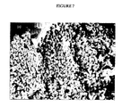
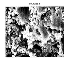
本発明のアノードは、慣用の電極に比べて、はるかに低い量の電子伝導性材料にて増加した電子伝導性を有する。さらに、発明のアノードは慣用のアノードに比べてはるかに低い量にて浸透性挙動を呈するが、伝導性相がランダムではないが、酸化物マトリックスの孔を被覆するという事実によると信じられている。慣用の方法(例えば、粉末を一緒に混合して焼結する−方法a)に従い製造されたLSC/YSZ、及び本発明(例えば、孔性YSZ層を形成させ、当該層をカソード材料の溶液に浸し、そして加熱する−方法b)に従い製造されたLSC/YSZの破断面のマイクロ構造を図7及び8に示す。YSZとLSCの粒子は、慣用の方法aに関して互いに完全に分散したことが観察できる。これらの電極に関しては、伝導性は低イオン伝導性粒子負荷においてYSZのそれとほとんど同じであり、そして浸透に関する挙動は、相対的に高い濃度のイオン伝導性材料においてのみ生じる。 The anode of the present invention has increased electron conductivity with a much lower amount of electron conducting material compared to conventional electrodes. In addition, the inventive anode exhibits osmotic behavior in much lower amounts than conventional anodes, but is believed to be due to the fact that the conductive phase is not random but covers the pores of the oxide matrix. . LSC / YSZ produced according to conventional methods (eg, mixing powders together and sintering—Method a) and the present invention (eg, porous YSZ layers are formed and the layers are made into a solution of cathode material. Immersion and heating-the microstructure of the fracture surface of the LSC / YSZ produced according to method b) is shown in FIGS. It can be observed that the YSZ and LSC particles were completely dispersed with respect to the conventional method a. For these electrodes, the conductivity is almost the same as that of YSZ at low ion conductive particle loading, and the permeation behavior occurs only at relatively high concentrations of ion conductive material.
如何なる理論にも拘束されることを意図しないが、発明者らは、コンポジット電極を通した2つの伝導機構の存在:(i)アノードとしてのLSCを通した電子の通路;及び(ii)YSZ及びLSCの両方を通したイオン通路、により浸透に関する挙動が説明できる。浸透閾値より下においては、コンポジットの伝導性はYSZの伝導性と類似していたことから、YSZ相を通したイオン伝導通路のみを示唆する。浸透閾値を超えると、伝導性は大きく増強されて、LSCペロブスカイトを通したイオン伝導性から電子伝導性への機構の変化に対応する。発明の電極(方法b)に関しては、LSCに対する前駆体の塩を含む溶液が孔性YSZの界面を通して吸着され得る。第2セラミック材料を含む伝導性酸化物相のナノメーター粒子層又は薄層が焼結後にYSZの表面に沿って相対的に均一に形成され得るから、低濃度においてさえも改善されたLSC粒子対粒子の接触がもたらされる。よって、第2セラミック材料の連続伝導性ペロブスカイト相は伝導性を増加させることができ、そして伝導性に関する浸透閾値が低負荷において見いだされ得る。慣用の電極(方法a)に関しては、浸透閾値ははるかに高い濃度のイオン伝導性材料においてであり、そのYSZとの混合のためである。 Without intending to be bound by any theory, we have the existence of two conduction mechanisms through the composite electrode: (i) the electron path through the LSC as the anode; and (ii) YSZ and The ion passage through both LSCs can explain the permeation behavior. Below the penetration threshold, the conductivity of the composite was similar to that of YSZ, suggesting only an ionic conduction path through the YSZ phase. Beyond the penetration threshold, the conductivity is greatly enhanced, corresponding to a change in mechanism from ionic to electronic conductivity through the LSC perovskite. For the inventive electrode (Method b), a solution containing a precursor salt to LSC can be adsorbed through the interface of the porous YSZ. Improved LSC particle pairs even at low concentrations because a nanometer particle layer or thin layer of conductive oxide phase comprising a second ceramic material can be formed relatively uniformly along the surface of YSZ after sintering. Particle contact is provided. Thus, the continuous conductive perovskite phase of the second ceramic material can increase conductivity and a permeation threshold for conductivity can be found at low loads. For conventional electrodes (method a), the permeation threshold is at a much higher concentration of ionically conductive material, due to its mixing with YSZ.
発明のアノードは、好ましくは、約0.5μmよりも大きな孔サイズを有する多数の孔を有する孔性構造を有する。全ての孔が約0.5μmを超える孔サイズを有する必要はないが、50%を超える孔、より好ましくは60%を超える孔、そしてもっとも好ましくは75%を超える孔が0.5μmを超える孔サイズを有することが好ましい。孔サイズは、孔の主な寸法に沿った距離を測定することにより決定することができる。本発明においては、多数の孔が約0.75μm、より好ましくは1μm、そしてもっとも好ましくは約1.5μmを超える孔サイズを有することが好ましい。 The anode of the invention preferably has a porous structure with a large number of pores having a pore size greater than about 0.5 μm. Not all holes need to have a pore size greater than about 0.5 μm, but more than 50% of the pores, more preferably more than 60%, and most preferably more than 75% of the pores exceed 0.5 μm. It is preferable to have a size. The hole size can be determined by measuring the distance along the main dimension of the hole. In the present invention, it is preferred that the multiple pores have a pore size of about 0.75 μm, more preferably 1 μm, and most preferably greater than about 1.5 μm.
イオン伝導性材料を分散させる前のアノードの孔度は、一般に、約55から約75%である。孔度は、好ましくは、焼結された生成物を水中に浸し、そして浸す前のその重量と浸した後のその重量を比較することにより測定され、Kim,H.,et al.,J.Am.Ceram.Soc.,85,1473(2002)に記載されている。上記の違いは孔に分散した水の重量を明らかにし、密度で割ったときに、孔の容量が明らかになる。孔度は、次に、孔の容量を単に焼結した生成物の全容量で割ることにより測定できる。もっとも好ましくは、電子伝導性材料を分散させる前の焼結した電解質生成物が約60%である。 The porosity of the anode before dispersing the ion conducting material is generally about 55 to about 75%. The porosity is preferably measured by soaking the sintered product in water and comparing its weight before soaking with its weight after soaking, Kim, H. et al. , Et al. , J .; Am. Ceram. Soc. 85, 1473 (2002). The above difference reveals the weight of water dispersed in the pores and when divided by the density reveals the pore volume. The porosity can then be measured by simply dividing the pore volume by the total volume of the sintered product. Most preferably, about 60% of the sintered electrolyte product prior to dispersing the electronically conductive material.
電子伝導性第2セラミック材料を分散させた後の電極の孔度は、概して、約10%から約75%、より好ましくは約10%から約40%、そしてもっとも好ましくは約12%から約30%であり得る。電極の孔度は、一部、使用された電子伝導性材料の量に依存することになり、図1に示される。 The electrode porosity after dispersing the electronically conductive second ceramic material is generally from about 10% to about 75%, more preferably from about 10% to about 40%, and most preferably from about 12% to about 30%. %. The porosity of the electrode will depend in part on the amount of electron conductive material used and is shown in FIG.
発明は、今、以下の非限定実施例を参照して説明される。
実施例
LSC−YSZ後コンポジット電極を2つの方法により製造した:(a)方法Aは慣用の酸化物粉末の物理的混合を含んだ;及び(b)方法Bは孔性YSZマトリックスの金属塩による含浸を含んだ。
The invention will now be described with reference to the following non-limiting examples.
Examples Post-LSC-YSZ composite electrodes were prepared by two methods: (a) Method A included physical mixing of conventional oxide powders; and (b) Method B was based on a metal salt of a porous YSZ matrix. Impregnation included.
比較法(a)
慣用のコンポジットに関して、YSZは、Tosoh社、東京、日本から購入して使用した。LSC(La0.7Sr0.3CrO3−δ)は、La,Sr及びCrの硝酸塩から合成した。La,Sr及びCrを蒸留水に溶解した後に、当該混合物を乾燥させて、800℃において空気中で一晩焼成した。この粉末を、次に、イソ−プロパノール存在下でモルタルと乳棒の中ですりつぶし、空気中で1400℃において4時間焼結し、そして次に再びすりつぶした。結果の粉末は、x線回析(XPD)測定により正確なペロブスカイト構造を有することが示された。最後に、以下により詳細に記載されるとおり、上記の酸化物粉末を混合し、それらを一軸でウエファーにプレスし、そして当該ウエファーを様々な温度に焼成することにより、LSC−YSZコンポジットを製造した。
Comparative method (a)
For conventional composites, YSZ was purchased from Tosoh, Tokyo, Japan and used. LSC (La 0.7 Sr 0.3 CrO 3 -δ) is, La, was synthesized from nitrates of Sr and Cr. After dissolving La, Sr and Cr in distilled water, the mixture was dried and calcined in air at 800 ° C. overnight. This powder was then ground in a mortar and pestle in the presence of iso-propanol, sintered in air at 1400 ° C. for 4 hours, and then ground again. The resulting powder was shown to have an accurate perovskite structure by x-ray diffraction (XPD) measurements. Finally, as described in more detail below, LSC-YSZ composites were produced by mixing the above oxide powders, pressing them uniaxially into a wafer, and firing the wafer to various temperatures. .
発明の方法(b)
含浸(impregnation)によりコンポジットを製造するため、方法Bでは、例えば、Gorte,R.J.,et al.,Adv.Materials,12,1465(2000),及びPark,S.,et al.,J.Electrochem.Soc.,148,A443(2001)に記載された方法を用いて、孔性YSZマトリックスを最初に製造した。YSZ粉末(8mol%のY2O3を含むZrO2、Tosoh TZ−84)を標準(received)として使用し、そして蒸留水、分散剤(Duramax 3005,Rohm & Haas)、結合剤(HA12及びB1000,Rohm & Hass)、及び孔形成剤(グラファイト及びポリメチルメタクリレート)と混合した。このスラリーを、約600μmの厚さを有する孔性セラミックウエファーをもたらすはずのテープに型取った(cast)。1550℃において焼成した後、水の含浸後のサンプルの重量の変化により示されるとおり、YSZウエファー及び長方形の断片が60%の孔度を有することがわかった。Kim,H.,et al.,J.Am.Ceram.Soc.,85,1473(2002)。適当な濃度のLa,Sr,及びCrの可溶性塩を含む溶液へのYSZの含浸により、LSCを次に孔性YSZへ添加した。十分な量のLa(NO3)3,Sr(NO3)3及びCr(NO3)3を用いて、約30から約40vol%の範囲のLSC濃度を有するコンポジットを製造した。
Method (b) of the invention
In order to produce a composite by impregnation, the process B is described, for example, in Gorte, R .; J. et al. , Et al. , Adv. Materials, 12, 1465 (2000), and Park, S .; , Et al. , J .; Electrochem. Soc. 148, A443 (2001), a porous YSZ matrix was first prepared. YSZ powder (ZrO 2 with 8 mol% Y 2 O 3 , Tosoh TZ-84) was used as received and distilled water, dispersant (Duramax 3005, Rohm & Haas), binder (HA12 and B1000). Rohm & Hass), and pore formers (graphite and polymethylmethacrylate). This slurry was cast into a tape that should result in a porous ceramic wafer having a thickness of about 600 μm. After firing at 1550 ° C., the YSZ wafer and rectangular pieces were found to have a porosity of 60%, as indicated by the change in weight of the sample after water impregnation. Kim, H .; , Et al. , J .; Am. Ceram. Soc. 85, 1473 (2002). LSC was then added to the porous YSZ by impregnation of YSZ into a solution containing the appropriate concentrations of soluble salts of La, Sr, and Cr. A sufficient amount of La (NO 3 ) 3 , Sr (NO 3 ) 3 and Cr (NO 3 ) 3 was used to produce composites having LSC concentrations in the range of about 30 to about 40 vol%.
電子伝導性は標準の4プローブDC法を用いて測定した。この方法においては、サンプルをホルダーに入れて、外部プラチナ箔を両末端に取り付けた。1286 Solartron電気化学界面からの電流をサンプルに通過させ、その間Tenna72−410Aマルチメーターを用いてサンプルを横切る電圧を監視した。伝導性は、一般に、空気中か又は加湿H2中の何れかで測定した。選択されたサンプルの相及びマイクロ構造も、XRD及び走査電子顕微鏡(SEM,JEOL,JSM−6300LV)を用いて研究した。 Electronic conductivity was measured using a standard 4-probe DC method. In this method, the sample was placed in a holder and an external platinum foil was attached to both ends. A current from a 1286 Solartron electrochemical interface was passed through the sample while the voltage across the sample was monitored using a Tenna 72-410A multimeter. Conductivity is generally measured either in or in a humidified H 2 air. The phase and microstructure of selected samples were also studied using XRD and scanning electron microscopy (SEM, JEOL, JSM-6300LV).
実施例1
一連の孔性コンポジットを上記の方法bを用いて製造することにより、電子伝導性酸化物材料が孔性マトリックス中に分散されたか否かを決定した。LSCの量を増加させた一連の材料の孔度を測定し、結果を図1に示す。この図面の中のLSC−YSZコンポジットは、1,100℃において焼成された。これらのデータに関して、伝導性酸化物の容量をその質量及び塊の密度から測定した。図面の中の線は、第2酸化物が孔を満たすと仮定しての、コンポジットの孔度の予測される変化である。孔度が予測どおりに低下するとの事実は、電子伝導性酸化物材料が焼成処理後の孔構造中に存在することを証明する。
Example 1
A series of porous composites were produced using method b above to determine whether the electron conductive oxide material was dispersed in the porous matrix. The porosity of a series of materials with increasing amounts of LSC was measured and the results are shown in FIG. The LSC-YSZ composite in this figure was fired at 1,100 ° C. For these data, the capacity of the conductive oxide was determined from its mass and mass density. The lines in the figure are the expected changes in the porosity of the composite, assuming that the second oxide fills the pores. The fact that the porosity decreases as expected proves that the electron conductive oxide material is present in the pore structure after the firing treatment.
図1に示すとおり、LSC−YSZコンポジットの孔度は、0%LSCにおいて60体積%(例えば、YSZマトリックスの孔度)から、約64体積%LSCにおいて0%まで低下する。コンポジット中のLSC濃度が約30−35体積%のオーダーであることにより、30−35体積%又は約30−35体積%において電極の孔度を残すことが好ましい。 As shown in FIG. 1, the porosity of the LSC-YSZ composite decreases from 60% by volume at 0% LSC (eg, the porosity of the YSZ matrix) to 0% at about 64% by volume LSC. Preferably, the LSC concentration in the composite is on the order of about 30-35% by volume, leaving the electrode porosity at 30-35% or about 30-35% by volume.
実施例2
アノード材料として有用なLSC−YSZコンポジットを上記の方法bに従い製造した。最適な焼成温度を決定するため、方法bを異なる温度において反復し、その結果を図2に示す。図2は、温度をだんだん増加させた焼成後の、約30体積重量%のLSCに相当するはずの負荷に対する、孔性YSZのLa,Sr及びCr塩への含浸後のXRDパターンを示す。LSCに相当するピーク、ペロブスカイト相(注目すべきは、41、46、58、68、及び78℃2θにおけるそれら)が約800℃において開始することが明らかになった。これらのピークは1,100℃までの焼成後に、より鋭くなるが、さらに高い焼成温度には新たな相が出現する。1,200℃まで、ピークは31度において出現し、SrZrO3の形成によると信じられる。1,400℃を下回る焼成温度に関しては、41度の近辺の領域において幾つかの重複するピークも存在し、おそらくは、クロム化合物、例えばCrO,CrO2(OH)y及びCr(OH)yに関連する。コンポジットの性能に逆効果を有するかもしれない不所望の成分の形成を防ぐためには、固体状態の反応が生じるよりも低い焼成温度においてコンポジットを製造することが好ましい。この場合、約1,200℃を下回る焼成温度においてコンポジットを製造することがもっとも好ましい。
Example 2
An LSC-YSZ composite useful as an anode material was prepared according to Method b above. In order to determine the optimum firing temperature, method b is repeated at different temperatures and the results are shown in FIG. FIG. 2 shows the XRD pattern after impregnation of porous YSZ with La, Sr and Cr salts for a load that should correspond to about 30% by volume LSC after firing at increasing temperatures. It was found that the peak corresponding to LSC, the perovskite phase (notably those at 41, 46, 58, 68, and 78 ° C. 2θ) started at about 800 ° C. These peaks become sharper after firing to 1,100 ° C., but new phases appear at higher firing temperatures. Up to 1200 ° C., the peak appears at 31 degrees and is believed to be due to the formation of SrZrO 3 . For firing temperatures below 1,400 ° C., there are also several overlapping peaks in the region around 41 degrees, probably related to chromium compounds such as CrO, CrO 2 (OH) y and Cr (OH) y . To do. In order to prevent the formation of undesired components that may have an adverse effect on the performance of the composite, it is preferred to produce the composite at a firing temperature lower than the solid state reaction occurs. In this case, it is most preferred to produce the composite at a firing temperature below about 1200 ° C.
実施例3
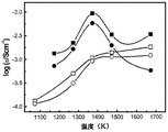
この実施例の目的は、コンポジットの電子伝導性に対する焼成温度の効果を研究することであり、その結果を図3に示す。2つのLSC−YSZコンポジットを製造したが、両者共に30体積%のLSCを有するが、一方は方法aを用いて製造し、そして他方は上記の方法bを用いて製造した。空気中及び加湿H2の両方において伝導性を700℃にて測定する前に、サンプルを、空気中で2時間さまざまな温度において焼成した。方法bにより製造されたコンポジットに関しては、1,100℃又は約1,100℃において伝導性が最大値まで温度まで上昇し、そしてさらに高い焼成温度においては低下することがわかった。これは、高温における第2相の形成後の、1,100℃におけるLSC相の形成と一致する。高温において形成されたコンポジットの伝導性がガス相のコンポジットに感受性であるのに対し、1,100℃において形成されたコンポジットはそうでないことも、興味を引く。LSCは広い範囲のP(O)2にわたり残るので、この観察は高温相がLSCであるという、さらなる証明である。
Example 3
The purpose of this example is to study the effect of firing temperature on the electronic conductivity of the composite, and the results are shown in FIG. Two LSC-YSZ composites were produced, both having 30% by volume LSC, but one was produced using Method a and the other was produced using Method b above. Prior to measuring conductivity in both air and humidified H 2 at 700 ° C., the samples were calcined in air for 2 hours at various temperatures. For composites made by method b, it has been found that the conductivity increases to a maximum at 1,100 ° C. or about 1,100 ° C. and decreases at higher firing temperatures. This is consistent with the formation of the LSC phase at 1,100 ° C. after the formation of the second phase at high temperature. It is also interesting that composites formed at high temperatures are sensitive to gas phase composites, whereas composites formed at 1,100 ° C. are not. This observation is further proof that the high temperature phase is LSC since LSC remains over a wide range of P (O) 2 .
方法aを用いて製造されたコンポジットに関しては、温度の上昇と共に、ずっと1,400℃まで、伝導性が増加し、そして空気中とH2中で測定された伝導性に大きな違いはない。焼成温度による伝導性増加の理由は、この場合極めて特別であるが、伝導性LSC相が初期サンプル調製において使用されたからである。これらのサンプルに関して、初期密度は低く、そして焼成がサンプル内の結合性を増強した。1,100℃をに加熱されたサンプルと1,400℃に加熱されたサンプルの間に観察された、より小さな伝導性の増加は、打ち消し効果によるもかもしれず、第2相の形成は伝導性を増加させ、そして稠密化は伝導性を増加させる。 For composites made using method a, the conductivity increases all the way up to 1,400 ° C. with increasing temperature, and there is no significant difference in conductivity measured in air and H 2 . The reason for the increase in conductivity with the firing temperature is very special in this case because the conductive LSC phase was used in the initial sample preparation. For these samples, the initial density was low and firing increased the bonding within the sample. The smaller increase in conductivity observed between the sample heated to 1100 ° C. and the sample heated to 1400 ° C. may be due to the cancellation effect, and the formation of the second phase is conductive. And densification increases conductivity.
実施例4
この実施例の目的は、LSC濃度の電子伝導性に対する効果を研究することであり、その結果を図4に示す。2つのLSC−YSZコンポジットを製造したが、両者共に1,100℃において2時間焼成したが、一方は方法aを用いて製造し、そして他方は上記の方法bを用いて製造した。LSCの量は体積%を用い、0から約100%まで変えた(方法aにより製造されたLSC−YSZコンポジットに関して100%)。次に、伝導性を、空気中及び加湿H2の両方において伝導性を700℃にて測定した。方法bにより製造されたサンプルは、相対的に低い体積フラクションのLSCにおいて、妥当な高い伝導性を呈した。これは、一部には、規定されたマトリックスへ含浸された材料がランダムな媒質であると考えることができないとの事実によると信じられる。たぶん、LSCはYSZ孔の壁の上に被覆を形成すると信じられる。
Example 4
The purpose of this example is to study the effect of LSC concentration on electronic conductivity, and the results are shown in FIG. Two LSC-YSZ composites were produced, both fired at 1,100 ° C. for 2 hours, one produced using method a and the other produced using method b above. The amount of LSC was varied from 0 to about 100% using volume% (100% for LSC-YSZ composite made by method a). The conductivity was then measured at 700 ° C. in both air and humidified H 2 . The sample produced by method b exhibited reasonably high conductivity in a relatively low volume fraction LSC. This is believed in part due to the fact that the material impregnated into the defined matrix cannot be considered a random medium. Perhaps the LSC is believed to form a coating on the wall of the YSZ hole.
混合された粉末から製造された比較用のサンプル、方法A、に関しては、LSCの重量フラクションが約80%に達するまで伝導性が低かった。そのような高い重量フラクションのLSCを要求され、浸透の概念に基づいて予測されるよりもはるかに高いという事実は、低い製造温度におけるこれらの粉末の不完全な焼結及びその結果の低密度によると信じられる。LSCの体積フラクションが約80%に達して初めて、材料が稠密になり、それにより伝導性が増加する。 For the comparative sample, Method A, made from the mixed powder, the conductivity was low until the weight fraction of LSC reached about 80%. The fact that such a high weight fraction LSC is required and is much higher than expected based on the concept of infiltration is due to the incomplete sintering of these powders at low manufacturing temperatures and the resulting low density. It is believed. Only after the volume fraction of LSC reaches about 80% does the material become dense, thereby increasing conductivity.
以下の実施例は、炭化水素被覆の形成の、コンポジットセラミックアノード材料に対する効果を研究する。 The following examples study the effect of forming a hydrocarbon coating on a composite ceramic anode material.
SOFCの作成
アノードを上記のとおりに製造した。セリア含有セラミックアノードを以下のとおりに製造した。稠密な電解質層及び孔性YSZマトリックスを、同時に、テープ鋳型法により製造した。孔形成剤のないグリーンテープ上にグラファイト及びポリ−メチルメタクリレート(PMMA)孔形成剤によりテープを型取る(cast)ことにより、2つの層、YSZのグリーンテープ(イットリウム安定化ジルコニア、Tosoh,8mol%のY2O3,TZ−84)を作成した。2層のテープを1800Kに焼成する(firing)ことで、600μm厚の孔性層により支持された60μm厚の稠密サイドを有するYSZウエファーをもたらした。孔性層の孔度は、水取込み測定により50〜70%であると決定された、Kim,H.,et al.,J.Am.Ceram.Soc.,85,1473(2002)。次に、YSZとLSM(La0.8Sr0.2MnO3、Praxair Surface Technologies)の50:50の混合物の粉末をペーストとしてウエファーの稠密サイドに塗布し、次に、1400Kに焼成することによりカソードを作成した。三番目に、孔性YSZ層をCe(NO3)3・6H2Oの水溶液に含浸し、そして723Kに焼成することにより硝酸イオンを分解してCeO2を形成させた。孔性層を次にCu(NO3)2・3H2Oの水溶液に含浸し、そして再び空気中で723Kに焼成することにより、硝酸塩を分解した。これらの実施例において使用されたセルの全部は、10重量%のCeO2を含み、金属を含まなかった。
SOFC Preparation An anode was manufactured as described above. A ceria-containing ceramic anode was produced as follows. A dense electrolyte layer and a porous YSZ matrix were simultaneously produced by the tape mold method. Two layers, YSZ green tape (yttrium stabilized zirconia, Tosoh, 8 mol%) by casting the tape with graphite and poly-methyl methacrylate (PMMA) pore former on green tape without pore former Y 2 O 3 , TZ-84). Firing the two-layer tape to 1800 K resulted in a YSZ wafer with a 60 μm thick dense side supported by a 600 μm thick porous layer. The porosity of the porous layer was determined to be 50-70% by water uptake measurement, Kim, H .; , Et al. , J .; Am. Ceram. Soc. 85, 1473 (2002). Next, a powder of a 50:50 mixture of YSZ and LSM (La 0.8 Sr 0.2 MnO 3 , Praxair Surface Technologies) was applied as a paste to the dense side of the wafer and then fired to 1400K A cathode was made. Third, the porous YSZ layer was impregnated with an aqueous solution of Ce (NO 3 ) 3 .6H 2 O and calcined to 723 K to decompose nitrate ions to form CeO 2 . The porous layer was then impregnated with an aqueous solution of Cu (NO 3 ) 2 .3H 2 O and again calcined in air to 723 K to decompose the nitrate. All of the cells used in these examples contained 10 wt% CeO 2 and no metal.
電子の接触は、Ptメッシュ及びPtペーストをカソードにおいて使用し、そしてAuメッシュ及びAuペーストをアノードにおいて使用して作成した。各セルは0.45cm2カソード面積を有し、Auペースト及びジルコニアベースの接着剤を用いて1.0cmのアルミナチューブ上にシールされた(Aremco,Ultra−Temp516)。 Electron contacts were made using Pt mesh and Pt paste at the cathode and Au mesh and Au paste at the anode. Each cell had a 0.45 cm 2 cathode area and was sealed onto a 1.0 cm alumina tube using Au paste and zirconia based adhesive (Aremco, Ultra-Temp 516).
SOFC及び発明のアノード及び比較用のアノード
上で製造された固形酸化物燃料セルを溶鉱炉の内部に置き、そしてH2流の中で2K/分において973Kに加熱した。H2,CH4,プロパン、及びn−ブタンを未希釈のセル(cell undiluted)に送った(fed)が、トルエンとデカンはN2との75mol%として送った。室温において流体であるものを含む全ての炭化水素を、Kim,H.,et al.,J.Electrochem.Soc.,48:A693(2001)に記載されるとおりに、リフォームすることなく直接アノードに送った。
Solid oxide fuel cells produced on SOFC and inventive anodes and comparative anodes were placed inside the blast furnace and heated to 973 K at 2 K / min in a H 2 stream. H 2 , CH 4 , propane, and n-butane were fed to the undiluted cell, while toluene and decane were sent as 75 mol% of N 2 . All hydrocarbons, including those that are fluid at room temperature, are treated by Kim, H. et al. , Et al. , J .; Electrochem. Soc. , 48: A693 (2001) and sent directly to the anode without reforming.
各セルに関する973Kにおける性能は、n−ブタン及びH2燃料によるそのV−I曲線により測定し、インピーダンススペクトルが選択されたサンプルに対して追加の情報を提供する。カソードと電解質は全ての場合に類似の様式にて製造されたから、燃料−セル及びインピーダンススペクトルにおける変化は、アノード内の変化のものであるとすることができる。燃料の流速はいつも室温において1cm3/秒より大きかったから、炭化水素燃料の変換はいつも1%未満であり、その結果、電気化学的酸化反応により生じる水は無視された。インピーダンススペクトルは、Gamry Instruments,モデルEIS300を用いて、オープンサーキット電位差(OCV)に接近して、定電流(galvanostatic)モードにて得た。 Performance in 973K for each cell was measured by the V-I curve by n- butane and H 2 fuel, the impedance spectra provide additional information to the selected sample. Since the cathode and electrolyte were manufactured in a similar manner in all cases, the changes in the fuel-cell and impedance spectra can be attributed to changes in the anode. Since the fuel flow rate was always greater than 1 cm 3 / sec at room temperature, the conversion of hydrocarbon fuel was always less than 1%, so that the water produced by the electrochemical oxidation reaction was ignored. Impedance spectra were obtained in galvanostatic mode using Gamry Instruments, model EIS300, approaching an open circuit potential difference (OCV).
n−ブタン内での処理後のSOFCアノード内に存在する炭素の量も測定した。これを達成するため、アノードサーメットサンプルを、クオーツ流反応機中で973Kにて様々な期間、流れるn−ブタンに暴露した。サンプルの重量又は流れるO2への暴露に際して形成されたCO及びCO2の量も測定した。重量の測定においては、サンプル温度を流れるHe中で973Kにランプし(ramped)、限定された期間、流れるn−ブタンに暴露し、そして次に流れるHeの中で冷却した。より長い暴露の後、サンプルを、冷却前に、流れるHeの中で973Kにおいて24時間フラッシュした。 The amount of carbon present in the SOFC anode after treatment in n-butane was also measured. To accomplish this, anode cermet samples were exposed to flowing n-butane for various periods at 973 K in a quartz flow reactor. The weight of the sample or the amount of CO and CO 2 formed upon exposure to flowing O 2 was also measured. For weight measurements, it was ramped to 973K in He flowing through the sample temperature, exposed to flowing n-butane for a limited period of time, and then cooled in flowing He. After longer exposure, the sample was flushed at 973K for 24 hours in flowing He before cooling.
アノード中の炭素含有量を測定するための第2の方法においては、サンプルを流れる反応機の中で973Kにおいてn−ブタンに暴露し、そしてHeと共にフラッシュした。次に、サンプルを、15% O2−85%He混合からなる流れるガスに暴露し、質量分光計を用いて反応機の流出物を監視した。サンプル中の炭素の量を、反応機に残ったCO及びCO2の量から計算した。形成された炭素の種類も、類似の様式にて、温度−プログラムされた酸化(TPO)により特性決定した。これらの測定において、アノードサンプルを973Kにおいて、30分間、流れるn−ブタンに暴露した。反応機を流れるHeの中で298Kに冷却し、そして再び10K/分の速度にて、15% O2−85%Heの流れるガス混合物の中で973Kにランプした。 In a second method for measuring the carbon content in the anode, the sample was exposed to n-butane at 973 K in a reactor flowing through the sample and flushed with He. Then, the samples were exposed to a gas flow consisting of 15% O 2 -85% He mixture was monitored effluent reactor using mass spectrometer. The amount of carbon in the sample was calculated from the amount of CO and CO 2 remaining in the reactor. The type of carbon formed was also characterized by temperature-programmed oxidation (TPO) in a similar manner. In these measurements, the anode sample was exposed to flowing n-butane at 973K for 30 minutes. Reactor was cooled to 298K in a He flow through, and again at 10K / min, and the lamp to 973K in the gas mixture flowing 15% O 2 -85% He.
原則として、質量分光計を用いて実施されたTPO実験は炭素の水素に対する比率の計算を可能にするはずであるが、検出器は被覆物中の水素の量を計算できるべきであるからであり;しかしながら、真空系の中の水に関するバックグラウンドシグナルはこの量の正確な測定を可能にさせるにはあまりに高すぎる。0.03gのグラファイト粉末のサンプル(Alpha Aesar,伝導性グレード99.995%)を同一の反応機の中にいれ、そして15% O2−85%He流れの中で10K/分にて加熱して比較した。グラファイトサンプルのSEM測定は、厚さ10μm未満の小板として粒子が形成されたことを示した。 In principle, a TPO experiment performed using a mass spectrometer should allow calculation of the carbon to hydrogen ratio, but the detector should be able to calculate the amount of hydrogen in the coating. However, the background signal for water in the vacuum system is too high to allow an accurate measurement of this amount. 0.03g of graphite powder samples (Alpha Aesar, conductive grade 99.995%) put into the same reactor, and heated at 10K / min in a 15% O 2 -85% He flow And compared. SEM measurements of the graphite sample showed that the particles were formed as platelets less than 10 μm thick.
発明のセラミックアノード及びSOFCの製造と試験
実施例5
アノード中に第2のセラミック材料としてセリアを含んだ、上で製造されたSOFCを、上記のとおりにしてn−ブタンへの暴露の前と後に、流れるH2中で試験し、結果を図5に示す。図5に示すとおり、優秀な性能は、セラミックアノードをブタンに接触させ、即ち炭化水素被覆をアノード上に形成させることにより達成された。
Production and testing of inventive ceramic anodes and SOFCs
Example 5
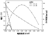
The SOFC produced above, containing ceria as the second ceramic material in the anode, was tested in flowing H 2 before and after exposure to n-butane as described above, and the results are shown in FIG. Shown in As shown in FIG. 5, excellent performance was achieved by contacting the ceramic anode with butane, ie, forming a hydrocarbon coating on the anode.
実施例6
孔性YSZをSrドープされたLaCrO3に含浸することにより上で製造されたSOFCも、上記のとおりにしてn−ブタンへの暴露の前と後に、流れるH2中で試験し、結果を図6に示す。図6に示すとおり、優秀な性能は、セラミックアノードをブタンに接触させ、即ち炭化水素被覆をアノード上に形成させることにより達成された。
Example 6
The SOFC produced above by impregnating porous YSZ with Sr-doped LaCrO 3 was also tested in flowing H 2 as described above, before and after exposure to n-butane, and the results are shown in FIG. It is shown in FIG. As shown in FIG. 6, excellent performance was achieved by contacting the ceramic anode with butane, ie, forming a hydrocarbon coating on the anode.
これらの実施例は、発明のセラミックコンポジットアノードを炭化水素により処理することで、炭化水素被覆をアノード上に形成することにより、性能を高めることが明らかとなった。 These examples have been shown to improve performance by treating the inventive ceramic composite anode with a hydrocarbon to form a hydrocarbon coating on the anode.
発明の別の態様、使用、及び利点は、明細書の考察及び本明細書にて記載される発明の実施から当業者には明らかとなる。明細書は例示と考えるべきであり、そして発明の範囲は従って、以下の請求の範囲によってのみ限定されることを意図する。 Other aspects, uses, and advantages of the invention will be apparent to those skilled in the art from consideration of the specification and practice of the invention described herein. The specification is to be regarded as illustrative and the scope of the invention is therefore intended to be limited only by the scope of the following claims.
Claims (34)
孔性セラミック材料の中に少なくとも一部被覆された電子伝導性材料
を含み、電子伝導性材料が第2セラミック材料からなる、アノード。 An anode comprising: a porous ceramic material comprising a first ceramic material; and an electronically conductive material at least partially coated within the porous ceramic material, wherein the electronically conductive material comprises a second ceramic material.
第1セラミック材料から孔性セラミック材料を作成し;
第2セラミック材料の塩を上記孔性セラミックマトリックスに添加し;そして
結果生じた構造を加熱することにより孔性第1セラミック材料の孔中の少なくとも一部に被覆された第2セラミック材料を有する孔性アノードを形成させること
を含む方法。 A method for making an anode comprising:
Creating a porous ceramic material from the first ceramic material;
Adding a salt of a second ceramic material to the porous ceramic matrix; and pores having a second ceramic material coated on at least a portion of the pores of the porous first ceramic material by heating the resulting structure Forming a conductive anode.
第1セラミック材料を含む2層のグリーンテープを作成し;そして
グリーンテープを約1,350から約1,650℃の範囲の温度において焼結させることにより製造する、請求項11記載の方法。 Porous ceramic material
12. The method of claim 11, wherein a two-layer green tape comprising a first ceramic material is made; and the green tape is produced by sintering at a temperature in the range of about 1,350 to about 1,650 ° C.
請求項1記載のアノード;
カソード;及び
カソードとアノードの間の少なくとも一部に被覆された電解質
を含む固形酸化物燃料セル。 A solid oxide fuel cell,
The anode of claim 1;
A solid oxide fuel cell comprising: a cathode; and an electrolyte coated on at least a portion between the cathode and the anode.
電解質材料を含む2層のグリーンテープを作成し;
グリーンテープを約1,350から約1,650℃の範囲の温度において焼結させることにより稠密なサイドと孔性のサイドを有する電解質材料の孔性材料を形成させ;
カソード組成物を稠密なサイドに適用して焼成することにより電解質材料の稠密なサイド上にカソードを作成し;
電解質材料の孔性材料の孔性サイドを第2セラミック材料に浸すことによりアノードを作成し;そして
アノードを加熱して固形酸化物燃料セルを作成すること
を含む方法。 A method of making a solid oxide fuel cell comprising:
Making two layers of green tape containing electrolyte material;
Sintering the green tape at a temperature in the range of about 1,350 to about 1,650 ° C. to form a porous material of an electrolyte material having a dense side and a porous side;
Creating a cathode on the dense side of the electrolyte material by applying the cathode composition to the dense side and firing;
Making an anode by immersing the porous side of the porous material of the electrolyte material in a second ceramic material; and heating the anode to create a solid oxide fuel cell.
Applications Claiming Priority (2)
| Application Number | Priority Date | Filing Date | Title |
|---|---|---|---|
| US38700902P | 2002-06-06 | 2002-06-06 | |
| PCT/US2003/017735 WO2003105252A2 (en) | 2002-06-06 | 2003-06-05 | Ceramic anodes and method of producing the same |
Publications (2)
| Publication Number | Publication Date |
|---|---|
| JP2005529464A true JP2005529464A (en) | 2005-09-29 |
| JP2005529464A5 JP2005529464A5 (en) | 2010-09-09 |
Family
ID=29736251
Family Applications (1)
| Application Number | Title | Priority Date | Filing Date |
|---|---|---|---|
| JP2004512218A Pending JP2005529464A (en) | 2002-06-06 | 2003-06-05 | Ceramic anode and method for producing the same |
Country Status (11)
| Country | Link |
|---|---|
| US (1) | US7740772B2 (en) |
| EP (1) | EP1530814A4 (en) |
| JP (1) | JP2005529464A (en) |
| KR (1) | KR20050036914A (en) |
| CN (1) | CN1672283A (en) |
| AU (1) | AU2003248623B2 (en) |
| CA (1) | CA2488273A1 (en) |
| EA (1) | EA007525B1 (en) |
| IL (1) | IL165386A0 (en) |
| MX (1) | MXPA04012068A (en) |
| WO (1) | WO2003105252A2 (en) |
Cited By (4)
| Publication number | Priority date | Publication date | Assignee | Title |
|---|---|---|---|---|
| JP2008164598A (en) * | 2006-12-15 | 2008-07-17 | General Electric Co <Ge> | System and method for solid oxide fuel cell surface analysis |
| JP2009110934A (en) * | 2007-08-31 | 2009-05-21 | Technical Univ Of Denmark | Electrode based on cerium oxide and stainless steel |
| JP2009541955A (en) * | 2006-07-01 | 2009-11-26 | フォルシュングスツェントルム・ユーリッヒ・ゲゼルシャフト・ミット・ベシュレンクテル・ハフツング | Combination of ceramic materials for anodes for high temperature fuel cells |
| JP2010177105A (en) * | 2009-01-30 | 2010-08-12 | Mitsubishi Heavy Ind Ltd | Power generation film for solid electrolyte fuel cell, and solid electrolyte fuel cell with the same |
Families Citing this family (47)
| Publication number | Priority date | Publication date | Assignee | Title |
|---|---|---|---|---|
| US7090891B2 (en) * | 2003-04-28 | 2006-08-15 | Curators Of The University Of Missouri | Method for fabricating nanostructured solid oxide fuel cells and cell components |
| JP4405196B2 (en) * | 2003-08-22 | 2010-01-27 | 新光電気工業株式会社 | Solid electrolyte fuel cell |
| JP4695828B2 (en) * | 2003-11-05 | 2011-06-08 | 本田技研工業株式会社 | Electrolyte / electrode assembly and method for producing the same |
| CN1985397B (en) | 2004-06-10 | 2012-07-04 | 丹麦科技大学 | Solid oxide fuel cell |
| KR20070083978A (en) * | 2004-10-05 | 2007-08-24 | 씨티피 히드로젠 코포레이션 | Conducting ceramics for electrochemical systems |
| CN100568598C (en) | 2004-12-28 | 2009-12-09 | 丹麦科技大学 | Make metal and glass, metal and metal or metal and the ceramic method that is connected |
| EP1844517B1 (en) | 2005-02-02 | 2010-04-21 | Technical University of Denmark | A method for producing a reversible solid oxid fuel cell |
| WO2006092912A1 (en) * | 2005-02-28 | 2006-09-08 | The Tokyo Electric Power Company, Incorporated | Solid oxide type fuel battery cell and process for producing the same |
| CA2606307A1 (en) * | 2005-04-21 | 2006-11-02 | The Regents Of The University Of California | Precursor infiltration and coating method |
| US20070037031A1 (en) * | 2005-07-13 | 2007-02-15 | Ion America Corporation | Cermet and ceramic interconnects for a solid oxide fuel cell |
| EP1760817B1 (en) * | 2005-08-31 | 2013-08-21 | Technical University of Denmark | Reversible solid oxide fuell cell stack and method for preparing same |
| US7864322B2 (en) | 2006-03-23 | 2011-01-04 | The Research Foundation Of State University Of New York | Optical methods and systems for detecting a constituent in a gas containing oxygen in harsh environments |
| PL2363392T3 (en) | 2006-03-30 | 2017-10-31 | Univ Pennsylvania | Styrylpyridine derivatives and their use for binding and imaging amyloid plaques |
| US8021799B2 (en) * | 2006-07-12 | 2011-09-20 | The Trustees Of The University Of Pennsylvania | High-performance ceramic anodes for use with strategic and other hydrocarbon fuels |
| US20080184892A1 (en) * | 2007-02-06 | 2008-08-07 | Ctp Hydrogen Corporation | Architectures for electrochemical systems |
| EP2244322A1 (en) * | 2009-04-24 | 2010-10-27 | Technical University of Denmark | Composite oxygen electrode and method for preparing same |
| WO2010135828A1 (en) * | 2009-05-26 | 2010-12-02 | Alex Mann | Low work function electrode |
| US9561476B2 (en) * | 2010-12-15 | 2017-02-07 | Praxair Technology, Inc. | Catalyst containing oxygen transport membrane |
| WO2013089895A1 (en) | 2011-12-15 | 2013-06-20 | Praxair Technology, Inc. | Composite oxygen transport membrane |
| US9486735B2 (en) | 2011-12-15 | 2016-11-08 | Praxair Technology, Inc. | Composite oxygen transport membrane |
| WO2014100376A1 (en) | 2012-12-19 | 2014-06-26 | Praxair Technology, Inc. | Method for sealing an oxygen transport membrane assembly |
| US9453644B2 (en) | 2012-12-28 | 2016-09-27 | Praxair Technology, Inc. | Oxygen transport membrane based advanced power cycle with low pressure synthesis gas slip stream |
| US10446855B2 (en) * | 2013-03-15 | 2019-10-15 | Lg Fuel Cell Systems Inc. | Fuel cell system including multilayer interconnect |
| US9611144B2 (en) | 2013-04-26 | 2017-04-04 | Praxair Technology, Inc. | Method and system for producing a synthesis gas in an oxygen transport membrane based reforming system that is free of metal dusting corrosion |
| US9938145B2 (en) | 2013-04-26 | 2018-04-10 | Praxair Technology, Inc. | Method and system for adjusting synthesis gas module in an oxygen transport membrane based reforming system |
| US9212113B2 (en) | 2013-04-26 | 2015-12-15 | Praxair Technology, Inc. | Method and system for producing a synthesis gas using an oxygen transport membrane based reforming system with secondary reforming and auxiliary heat source |
| US9296671B2 (en) | 2013-04-26 | 2016-03-29 | Praxair Technology, Inc. | Method and system for producing methanol using an integrated oxygen transport membrane based reforming system |
| MX2016004495A (en) | 2013-10-07 | 2016-06-16 | Praxair Technology Inc | Ceramic oxygen transport membrane array reforming reactor. |
| US9573094B2 (en) | 2013-10-08 | 2017-02-21 | Praxair Technology, Inc. | System and method for temperature control in an oxygen transport membrane based reactor |
| CN105764842B (en) | 2013-12-02 | 2018-06-05 | 普莱克斯技术有限公司 | Use the method and system of the production hydrogen of the reforming system based on oxygen transport film with two process transform |
| US9878080B2 (en) * | 2014-01-14 | 2018-01-30 | CardioFlow Technologies, LLC | Apparatus and methods for optimizing intra cardiac filling pressures, heart rate, and cardiac output |
| US9562472B2 (en) | 2014-02-12 | 2017-02-07 | Praxair Technology, Inc. | Oxygen transport membrane reactor based method and system for generating electric power |
| WO2015160609A1 (en) | 2014-04-16 | 2015-10-22 | Praxair Technology, Inc. | Method and system for oxygen transport membrane enhanced integrated gasifier combined cycle (igcc) |
| WO2016057164A1 (en) | 2014-10-07 | 2016-04-14 | Praxair Technology, Inc | Composite oxygen ion transport membrane |
| GB2524638B (en) * | 2015-02-06 | 2016-04-06 | Ceres Ip Co Ltd | Electrolyte forming process |
| US10441922B2 (en) | 2015-06-29 | 2019-10-15 | Praxair Technology, Inc. | Dual function composite oxygen transport membrane |
| US10118823B2 (en) | 2015-12-15 | 2018-11-06 | Praxair Technology, Inc. | Method of thermally-stabilizing an oxygen transport membrane-based reforming system |
| US9938146B2 (en) | 2015-12-28 | 2018-04-10 | Praxair Technology, Inc. | High aspect ratio catalytic reactor and catalyst inserts therefor |
| CN109070014A (en) | 2016-04-01 | 2018-12-21 | 普莱克斯技术有限公司 | Oxygen transport membrane containing catalyst |
| US10692653B2 (en) | 2017-10-27 | 2020-06-23 | Yageo Corporation | Ceramic sintered body and passive component including the same |
| TWI660932B (en) * | 2017-10-30 | 2019-06-01 | 國巨股份有限公司 | Ceramic sintered body and passive component including the same |
| EP3797085A1 (en) | 2018-05-21 | 2021-03-31 | Praxair Technology, Inc. | Otm syngas panel with gas heated reformer |
| WO2019245298A1 (en) * | 2018-06-20 | 2019-12-26 | 주식회사 엘지화학 | Connecting material for solid oxide fuel cell, manufacturing method thereof, and solid oxide fuel cell comprising same |
| CN111244515B (en) * | 2020-03-18 | 2021-10-01 | 湖北大学 | Perovskite type LaNiO containing calcium3Composite electrolyte, fuel cell and preparation method thereof |
| KR102460596B1 (en) * | 2020-09-14 | 2022-10-27 | 명지대학교 산학협력단 | Anode manufacturing method for protonic ceramics fuel cells using impregnation method and anode for fuel cell manufactured using same |
| KR102458353B1 (en) * | 2020-09-14 | 2022-10-21 | 명지대학교 산학협력단 | Anode manufacturing method for fuel cell using impregnation method and anode for fuel cell manufactured using same |
| CN112421021A (en) * | 2020-11-26 | 2021-02-26 | 格林美(江苏)钴业股份有限公司 | Coating method of anode material adopted by lithium ion battery |
Citations (4)
| Publication number | Priority date | Publication date | Assignee | Title |
|---|---|---|---|---|
| JPH07245112A (en) * | 1994-03-07 | 1995-09-19 | Fuji Electric Co Ltd | Solid electrolyte fuel cell |
| JP2000200614A (en) * | 1999-01-06 | 2000-07-18 | Mitsubishi Materials Corp | Electrode for solid-oxide fuel cell and its manufacture |
| JP2001224963A (en) * | 2000-02-16 | 2001-08-21 | Nissan Motor Co Ltd | Catalytic composition, its manufacturing method and its using method |
| JP2002538597A (en) * | 1999-03-03 | 2002-11-12 | ザ トラスティーズ オブ ザ ユニバーシティ オブ ペンシルベニア | Method for producing anode for solid oxide fuel cell |
Family Cites Families (16)
| Publication number | Priority date | Publication date | Assignee | Title |
|---|---|---|---|---|
| US53471A (en) * | 1866-03-27 | Improvement in buttons | ||
| US29231A (en) * | 1860-07-24 | Punching-machine | ||
| US3881957A (en) * | 1972-03-17 | 1975-05-06 | Universal Oil Prod Co | Electrochemical cell comprising a catalytic electrode of a refractory oxide and a carbonaceous pyropolymer |
| DK167163B1 (en) * | 1991-02-13 | 1993-09-06 | Risoe Forskningscenter | FAST OXIDE FUEL CELLS FOR OXIDATION OF CH4 |
| US5273837A (en) * | 1992-12-23 | 1993-12-28 | Corning Incorporated | Solid electrolyte fuel cells |
| GB9403198D0 (en) * | 1994-02-19 | 1994-04-13 | Rolls Royce Plc | A solid oxide fuel cell stack |
| US5543239A (en) * | 1995-04-19 | 1996-08-06 | Electric Power Research Institute | Electrode design for solid state devices, fuel cells and sensors |
| US5670270A (en) * | 1995-11-16 | 1997-09-23 | The Dow Chemical Company | Electrode structure for solid state electrochemical devices |
| US5993986A (en) * | 1995-11-16 | 1999-11-30 | The Dow Chemical Company | Solide oxide fuel cell stack with composite electrodes and method for making |
| US5908713A (en) | 1997-09-22 | 1999-06-01 | Siemens Westinghouse Power Corporation | Sintered electrode for solid oxide fuel cells |
| US6458170B1 (en) * | 1998-12-03 | 2002-10-01 | The Regents Of The University Of California | Method for making thin, flat, dense membranes on porous substrates |
| US6228521B1 (en) | 1998-12-08 | 2001-05-08 | The University Of Utah Research Foundation | High power density solid oxide fuel cell having a graded anode |
| US6558831B1 (en) * | 2000-08-18 | 2003-05-06 | Hybrid Power Generation Systems, Llc | Integrated SOFC |
| US6492051B1 (en) * | 2000-09-01 | 2002-12-10 | Siemens Westinghouse Power Corporation | High power density solid oxide fuel cells having improved electrode-electrolyte interface modifications |
| US6653009B2 (en) * | 2001-10-19 | 2003-11-25 | Sarnoff Corporation | Solid oxide fuel cells and interconnectors |
| US6958196B2 (en) * | 2003-02-21 | 2005-10-25 | Trustees Of The University Of Pennsylvania | Porous electrode, solid oxide fuel cell, and method of producing the same |
-
2003
- 2003-06-05 KR KR1020047019682A patent/KR20050036914A/en not_active Application Discontinuation
- 2003-06-05 MX MXPA04012068A patent/MXPA04012068A/en unknown
- 2003-06-05 IL IL16538603A patent/IL165386A0/en unknown
- 2003-06-05 CN CNA038173557A patent/CN1672283A/en active Pending
- 2003-06-05 EP EP03757352A patent/EP1530814A4/en not_active Withdrawn
- 2003-06-05 US US10/454,783 patent/US7740772B2/en not_active Expired - Fee Related
- 2003-06-05 CA CA002488273A patent/CA2488273A1/en not_active Abandoned
- 2003-06-05 AU AU2003248623A patent/AU2003248623B2/en not_active Ceased
- 2003-06-05 EA EA200401591A patent/EA007525B1/en not_active IP Right Cessation
- 2003-06-05 JP JP2004512218A patent/JP2005529464A/en active Pending
- 2003-06-05 WO PCT/US2003/017735 patent/WO2003105252A2/en active Search and Examination
Patent Citations (4)
| Publication number | Priority date | Publication date | Assignee | Title |
|---|---|---|---|---|
| JPH07245112A (en) * | 1994-03-07 | 1995-09-19 | Fuji Electric Co Ltd | Solid electrolyte fuel cell |
| JP2000200614A (en) * | 1999-01-06 | 2000-07-18 | Mitsubishi Materials Corp | Electrode for solid-oxide fuel cell and its manufacture |
| JP2002538597A (en) * | 1999-03-03 | 2002-11-12 | ザ トラスティーズ オブ ザ ユニバーシティ オブ ペンシルベニア | Method for producing anode for solid oxide fuel cell |
| JP2001224963A (en) * | 2000-02-16 | 2001-08-21 | Nissan Motor Co Ltd | Catalytic composition, its manufacturing method and its using method |
Cited By (4)
| Publication number | Priority date | Publication date | Assignee | Title |
|---|---|---|---|---|
| JP2009541955A (en) * | 2006-07-01 | 2009-11-26 | フォルシュングスツェントルム・ユーリッヒ・ゲゼルシャフト・ミット・ベシュレンクテル・ハフツング | Combination of ceramic materials for anodes for high temperature fuel cells |
| JP2008164598A (en) * | 2006-12-15 | 2008-07-17 | General Electric Co <Ge> | System and method for solid oxide fuel cell surface analysis |
| JP2009110934A (en) * | 2007-08-31 | 2009-05-21 | Technical Univ Of Denmark | Electrode based on cerium oxide and stainless steel |
| JP2010177105A (en) * | 2009-01-30 | 2010-08-12 | Mitsubishi Heavy Ind Ltd | Power generation film for solid electrolyte fuel cell, and solid electrolyte fuel cell with the same |
Also Published As
| Publication number | Publication date |
|---|---|
| IL165386A0 (en) | 2006-01-15 |
| WO2003105252A2 (en) | 2003-12-18 |
| EA200401591A1 (en) | 2005-06-30 |
| MXPA04012068A (en) | 2005-03-07 |
| CA2488273A1 (en) | 2003-12-18 |
| EP1530814A2 (en) | 2005-05-18 |
| US7740772B2 (en) | 2010-06-22 |
| WO2003105252A3 (en) | 2004-03-04 |
| EA007525B1 (en) | 2006-10-27 |
| EP1530814A4 (en) | 2009-05-27 |
| AU2003248623A1 (en) | 2003-12-22 |
| CN1672283A (en) | 2005-09-21 |
| KR20050036914A (en) | 2005-04-20 |
| AU2003248623B2 (en) | 2009-05-14 |
| US20040043272A1 (en) | 2004-03-04 |
Similar Documents
| Publication | Publication Date | Title |
|---|---|---|
| US7740772B2 (en) | Ceramic anodes and method of producing the same | |
| US6958196B2 (en) | Porous electrode, solid oxide fuel cell, and method of producing the same | |
| US20070117006A1 (en) | Direct Fabrication of Copper Cermet for Use in Solid Oxide Fuel Cell | |
| US20060113034A1 (en) | Electrochemical cell architecture and method of making same via controlled powder morphology | |
| JP5591526B2 (en) | Solid oxide cell and solid oxide cell stack | |
| US20080193803A1 (en) | Precursor Infiltration and Coating Method | |
| JP2005529464A5 (en) | ||
| US8021799B2 (en) | High-performance ceramic anodes for use with strategic and other hydrocarbon fuels | |
| JP2009059697A (en) | Metal support type solid oxide fuel cell | |
| JP2009541955A (en) | Combination of ceramic materials for anodes for high temperature fuel cells | |
| US20040185327A1 (en) | High performance ceramic anodes and method of producing the same |
Legal Events
| Date | Code | Title | Description |
|---|---|---|---|
| A621 | Written request for application examination |
Free format text: JAPANESE INTERMEDIATE CODE: A621 Effective date: 20060517 |
|
| A131 | Notification of reasons for refusal |
Free format text: JAPANESE INTERMEDIATE CODE: A131 Effective date: 20100119 |
|
| A601 | Written request for extension of time |
Free format text: JAPANESE INTERMEDIATE CODE: A601 Effective date: 20100419 |
|
| A602 | Written permission of extension of time |
Free format text: JAPANESE INTERMEDIATE CODE: A602 Effective date: 20100426 |
|
| A601 | Written request for extension of time |
Free format text: JAPANESE INTERMEDIATE CODE: A601 Effective date: 20100519 |
|
| A602 | Written permission of extension of time |
Free format text: JAPANESE INTERMEDIATE CODE: A602 Effective date: 20100526 |
|
| A601 | Written request for extension of time |
Free format text: JAPANESE INTERMEDIATE CODE: A601 Effective date: 20100621 |
|
| A602 | Written permission of extension of time |
Free format text: JAPANESE INTERMEDIATE CODE: A602 Effective date: 20100628 |
|
| A524 | Written submission of copy of amendment under article 19 pct |
Free format text: JAPANESE INTERMEDIATE CODE: A524 Effective date: 20100720 |
|
| A521 | Request for written amendment filed |
Free format text: JAPANESE INTERMEDIATE CODE: A821 Effective date: 20100720 |
|
| A02 | Decision of refusal |
Free format text: JAPANESE INTERMEDIATE CODE: A02 Effective date: 20110620 |