JP5591183B2 - Electric motor and exhaust fan - Google Patents
Electric motor and exhaust fan Download PDFInfo
- Publication number
- JP5591183B2 JP5591183B2 JP2011122542A JP2011122542A JP5591183B2 JP 5591183 B2 JP5591183 B2 JP 5591183B2 JP 2011122542 A JP2011122542 A JP 2011122542A JP 2011122542 A JP2011122542 A JP 2011122542A JP 5591183 B2 JP5591183 B2 JP 5591183B2
- Authority
- JP
- Japan
- Prior art keywords
- bracket
- stator
- shaft
- substrate
- rotor
- Prior art date
- Legal status (The legal status is an assumption and is not a legal conclusion. Google has not performed a legal analysis and makes no representation as to the accuracy of the status listed.)
- Active
Links
- 239000000758 substrate Substances 0.000 claims description 41
- 229910052751 metal Inorganic materials 0.000 claims description 25
- 239000002184 metal Substances 0.000 claims description 25
- 229920005989 resin Polymers 0.000 claims description 11
- 239000011347 resin Substances 0.000 claims description 11
- 238000001514 detection method Methods 0.000 claims description 10
- 229920005992 thermoplastic resin Polymers 0.000 claims description 6
- 230000001747 exhibiting effect Effects 0.000 claims 1
- 238000009423 ventilation Methods 0.000 description 14
- 230000002159 abnormal effect Effects 0.000 description 8
- XEEYBQQBJWHFJM-UHFFFAOYSA-N Iron Chemical group [Fe] XEEYBQQBJWHFJM-UHFFFAOYSA-N 0.000 description 6
- 230000006866 deterioration Effects 0.000 description 6
- 238000000465 moulding Methods 0.000 description 5
- 239000004734 Polyphenylene sulfide Substances 0.000 description 3
- 238000009413 insulation Methods 0.000 description 3
- 229920000069 polyphenylene sulfide Polymers 0.000 description 3
- 238000004804 winding Methods 0.000 description 3
- 238000010586 diagram Methods 0.000 description 2
- 230000000694 effects Effects 0.000 description 2
- 239000012212 insulator Substances 0.000 description 2
- 230000000149 penetrating effect Effects 0.000 description 2
- 230000005855 radiation Effects 0.000 description 2
- 230000005856 abnormality Effects 0.000 description 1
- 229910052782 aluminium Inorganic materials 0.000 description 1
- XAGFODPZIPBFFR-UHFFFAOYSA-N aluminium Chemical compound [Al] XAGFODPZIPBFFR-UHFFFAOYSA-N 0.000 description 1
- 238000009833 condensation Methods 0.000 description 1
- 230000005494 condensation Effects 0.000 description 1
- 238000007796 conventional method Methods 0.000 description 1
- 230000007423 decrease Effects 0.000 description 1
- 238000001035 drying Methods 0.000 description 1
- 238000010292 electrical insulation Methods 0.000 description 1
- 238000004519 manufacturing process Methods 0.000 description 1
- 238000004382 potting Methods 0.000 description 1
- 238000005245 sintering Methods 0.000 description 1
- 229910000679 solder Inorganic materials 0.000 description 1
- 229920001187 thermosetting polymer Polymers 0.000 description 1
Images


Landscapes
- Motor Or Generator Frames (AREA)
- Connection Of Motors, Electrical Generators, Mechanical Devices, And The Like (AREA)
- Brushless Motors (AREA)
Description
本発明は、電動機および換気扇に関する。 The present invention relates to an electric motor and a ventilation fan.
電動機としてのDCブラシレスモーターの構造は、コイルが巻回されたステーターが嵌め込まれたケースの中にローターが配置される。ローターにはシャフトが連結される。ケースの中に設けられた樹脂製のブラケットによって、ベアリングなどの金属製の軸受けを介してシャフトが保持される。そして、シャフト貫通穴が設けられたプリント基板がステーターに固定される(例えば、特許文献1を参照)。また、DCブラシレスモーターには、ローターを回転させる電流を発生させる駆動回路と、その駆動回路を制御するマイコンが備えられる。 In the structure of a DC brushless motor as an electric motor, a rotor is disposed in a case in which a stator around which a coil is wound is fitted. A shaft is connected to the rotor. The shaft is held by a resin bracket provided in the case via a metal bearing such as a bearing. And the printed circuit board provided with the shaft through-hole is fixed to the stator (for example, refer patent document 1). Further, the DC brushless motor is provided with a drive circuit for generating a current for rotating the rotor and a microcomputer for controlling the drive circuit.
上記従来の技術によれば、ローターを回転させる電流を発生させる駆動回路を制御するマイコンは、ローターの位置検出手段であるホールICの信号を元に制御を行っている。そのため、ローターの位置検出精度が低くなってしまった場合、モーターの誘起電圧位相と駆動回路から発生するモーター相電流位相にズレが発生し、効率の悪化や異常音の発生を招いてしまう。 According to the above conventional technique, the microcomputer that controls the drive circuit that generates the current for rotating the rotor performs the control based on the signal of the Hall IC that is the position detection means of the rotor. For this reason, when the rotor position detection accuracy is low, a deviation occurs between the induced voltage phase of the motor and the motor phase current phase generated from the drive circuit, leading to deterioration of efficiency and generation of abnormal noise.
ここで、ブラケットに用いられる樹脂としては、成型製がよく強度が強いPPS樹脂といった熱可塑性樹脂が用いられる場合がある。しかしながら、DCブラシレスモーターの駆動により軸受け部分が高温となった場合、ブラケットと軸受けとの間に、樹脂と金属との線膨張係数の差により隙間が発生する場合がある。この隙間により、ローターの位置検出精度が低くなってしまうという問題があった。 Here, as a resin used for the bracket, a thermoplastic resin such as a PPS resin that is well-molded and has high strength may be used. However, when the bearing portion becomes hot due to the driving of the DC brushless motor, a gap may be generated between the bracket and the bearing due to a difference in linear expansion coefficient between the resin and the metal. Due to this gap, there is a problem that the position detection accuracy of the rotor is lowered.
そこで、線膨張係数が金属と近く、熱による変形が発生しにくいBMC樹脂などの熱硬化性樹脂をブラケットに用いた場合、熱可塑性樹脂と比較して成型のサイクルタイムが長くなり加工費がアップしてしまう。また、成型性が悪く薄肉化が困難であるため、ローターとホールICとの距離が大きくなるため、ローターの位置検出精度が低くなり、効率の悪化や異常音の発生を招いてしまうという問題があった。 Therefore, when a thermosetting resin such as BMC resin, which has a linear expansion coefficient close to that of metal and is unlikely to be deformed by heat, is used for the bracket, the molding cycle time is longer and the processing cost is increased compared to thermoplastic resin. Resulting in. In addition, since the moldability is poor and it is difficult to reduce the thickness, the distance between the rotor and the Hall IC is increased, so that the position detection accuracy of the rotor is lowered, leading to deterioration in efficiency and generation of abnormal noise. there were.
本発明は、上記に鑑みてなされたものであって、ローターの位置検出精度が低下するのを抑えて、効率の悪化の抑制や異常音の発生の抑制を図ることのできる電動機を得ることを目的とする。 The present invention has been made in view of the above, and it is an object of the present invention to obtain an electric motor capable of suppressing deterioration in efficiency and generation of abnormal noise while suppressing reduction in rotor position detection accuracy. Objective.
上述した課題を解決し、目的を達成するために、本発明は、ステーターと、ステーターを内部に収容するフレームと、ステーターの内側に配置されて円環形状を呈するローターと、ローターに連結されたシャフトと、シャフトの外周に立設する軸保持部が設けられた樹脂製のブラケットと、シャフトを回転可能に支持する軸受けと、軸保持部に対してシャフト側に設けられた金属製の金属ハウジングと、を備え、軸保持部は、金属ハウジングを介して軸受けを保持することを特徴とする。 In order to solve the above-described problems and achieve the object, the present invention includes a stator, a frame that houses the stator, a rotor that is disposed inside the stator and has an annular shape, and is connected to the rotor. A shaft, a resin-made bracket provided with a shaft holding portion standing on the outer periphery of the shaft, a bearing for rotatably supporting the shaft, and a metal metal housing provided on the shaft side with respect to the shaft holding portion The shaft holding part holds the bearing via the metal housing.
本発明によれば、ステーターとブラケットとの位置ずれ、および基板とブラケットとの位置ずれを抑えて、ホールICとステーターとの位置決め精度が低下するのを抑えて、効率の悪化の抑制や異常音の発生の抑制を図ることができるという効果を奏する。 According to the present invention, the positional deviation between the stator and the bracket and the positional deviation between the substrate and the bracket are suppressed, the deterioration of the positioning accuracy between the Hall IC and the stator is suppressed, the deterioration of the efficiency and the abnormal noise are suppressed. There is an effect that it is possible to suppress the occurrence of.
以下に、本発明の実施の形態にかかる電動機および換気扇を図面に基づいて詳細に説明する。なお、この実施の形態によりこの発明が限定されるものではない。 Hereinafter, an electric motor and a ventilation fan according to an embodiment of the present invention will be described in detail with reference to the drawings. Note that the present invention is not limited to the embodiments.
実施の形態1.
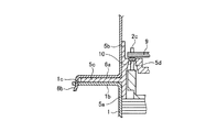
図1は、本発明の実施の形態1にかかるDCブラシレスモーターの側面図である。図2は、図1のA部分を拡大した部分拡大断面図である。図3は、ブラケット部分の平面図であって、図1に示す矢印Bに沿って見た矢視図である。図4は、基板の平面図である。図5は、ステーターの平面図である。図6は、ブラケットの底面図であって、図1に示す矢印Cに沿って見た矢視図である。図7−1は、ブラケットのステーター側位置決め突起部分を拡大した部分拡大図である。図7−2は、図7−1に示す矢印Dに沿ってステーター側位置決め突起を見た矢視図である。図8は、電動機の回路ブロック図である。なお、図1では、DCブラシレスモーター31の内部構造を説明するために、一部を断面で示している。
FIG. 1 is a side view of the DC brushless motor according to the first embodiment of the present invention. FIG. 2 is a partially enlarged cross-sectional view in which the portion A of FIG. 1 is enlarged. FIG. 3 is a plan view of the bracket portion, and is an arrow view seen along the arrow B shown in FIG. FIG. 4 is a plan view of the substrate. FIG. 5 is a plan view of the stator. FIG. 6 is a bottom view of the bracket and is an arrow view seen along the arrow C shown in FIG. FIG. 7-1 is a partially enlarged view of the bracket-side positioning protrusion portion of the bracket. FIG. 7-2 is an arrow view of the stator side positioning protrusion as seen along the arrow D shown in FIG. FIG. 8 is a circuit block diagram of the electric motor. In FIG. 1, in order to explain the internal structure of the DC
電動機としてのDCブラシレスモーター31では、フレーム1とカバー6とで構成される外郭の内部に各要素が納められている。ハウジング1aを持った金属性のフレーム1の内径には、ステーター2が圧入されている。ステーター2は、鉄心2aにコイル2bが巻回されて構成される。
In the DC
ハウジング1aには、軸受け4に適切な荷重を与えるためのスプリング14が挿入される。ローターシャフト3は、ステーター2の内部に配置される。ローターシャフト3は、シャフト3aに軸受け4とローター3bとを備えて構成される。軸受け4は、シャフト3aを回転可能に支持する。ローター3bは、円環形状を呈する。
A
ブラケット5は、ステーター側突起5aとブラケットフランジ5cとを備えている。ステーター側突起5aをフレーム1の内径に挿入するとともに、フレーム1に形成されたフレームフランジ1bとカバー6に形成されたカバーフランジ6aとでブラケットフランジ5cを挟みこむことで、フレーム1とカバー6で構成される外郭に対するブラケット5の位置決めと固定が行われる。
The
ブラケット5には、ブラケットハウジング(軸保持部)5eが一体形成されている。ブラケットハウジング5eは、シャフト3aの外周に立設され、本実施の形態では、シャフト3aの周囲を囲むように形成されている。ブラケットハウジング5eの内側、すなわちブラケットハウジング5eに対するシャフト3a側には、金属製の金属ハウジング8が設けられる。
The
上述したように、ステーター側突起5aをフレーム1の内径に挿入してブラケット5の位置決めと固定を行うことで、ハウジング1aの中心と金属ハウジング8の中心とが位置合わせされるようになっている。また、軸受け4a(4)は、フレーム1に保持され、軸受け4b(4)は、金属ハウジング8を介してブラケットハウジング5eに保持される。すなわち、フレーム1およびブラケットハウジング5e(金属ハウジング8)が、それぞれ軸受け4(4a,4b)を介してシャフト3aを保持する。
As described above, by inserting the
ブラケット5には、ピン2c(図5も参照)を通すための貫通穴5dが形成されている。ピン2cは、ステーター2に埋設されて基板9と電気接続するためのものである。貫通穴5dは、ステーター2へのピン2cの埋設ピッチに合わせて形成されている。
The
貫通穴5dは、ステーター2側から基板9側に向けてその直径が小さくなるように形成されており、基板9側でブラケット5とピン2cとのスキマが最小となる。貫通穴5dには、ピン2cを貫通させた上で、ステーター2側から基板9側への湿気進入を抑制するように、ピン2cとブラケット5との隙間全面に速乾性のある防湿処理10が施される。
The through
基板9は、ブラケット5に対してステーター2側の反対側に取り付けられる。基板9は、貫通穴5dを貫通したピン2cとはんだ等で接合される。図4,8に示すように、基板9には、ローター位置検出手段であるホールIC9b、モーターを回転させるための駆動回路9g、電源回路9f、マイコン9h等を構成する電子部品9aが取り付けられている。
The
基板9には、電子部品9aから発生する熱を放熱するためのアルミ製の放熱フィン9iが取り付けられている(図1を参照)。放熱フィン9iには、クッション性を有する放熱シート11と、電気絶縁性を有する絶縁シート12とを取り付けた後に、金属性のカバー6が取り付けられる。
The
カバー6は、ブラケット5のカバー側突起5bに嵌合する。また、図2に示すように、フレーム1のフレームフランジ1bと、ブラケット5のブラケットフランジ5cと、カバー6のカバーフランジ6aとを合わせて、フレーム穴1cにカバー突起6bを挿入してカバー突起6bを折り曲げることで、フレーム1とブラケット5とカバー6とが組み合わされた状態で固定される。
The
ブラケットフランジ5c、フレームフランジ1b、カバーフランジ6aにはネジ穴7が設けられており(図3も参照)、このネジ穴7を用いてDCブラシレスモーター31が換気扇などの製品にネジ止めされる。
Screw holes 7 are provided in the
ブラケット5には、樹脂製のものが用いられる。ブラケット5を樹脂製にすることで絶縁性を有するため、コイル2b、ピン2c、基板9と、フレーム1、カバー6の半径方向への沿面距離を確保することができる。また、軸方向へはコイル2bとブラケット5のスペースを接触するまで最小限に設置でき、基板9とブラケット5のスペースも接触するまで最小限に設置できるため小型化を図ることができる。
The
また、ブラケット5のステーター側突起5aがフレーム1の内径に挿入されるため、ブラケット5の金属ハウジング8とフレーム1のハウジング1aとの同軸度を良好にでき、精度よく組立を行うことができる。
Further, since the stator-
ブラケットフランジ5cをフレームフランジ1bとカバーフランジ6aとで挟み込み、フレームフランジ1bとカバーフランジ6aを固定することで、ブラケットフランジ5cを簡単に固定できる。また、軸方向に対する輸送振動や落下衝撃のストレスが基板9とピン2cとの接合部や基板9自体に加わることを抑えることができるため、基板9とピン2cとの接合部や基板9自体の品質低下を抑制することができる。
The
ブラケット5に形成された貫通穴5dは、ステーター2側の直径を大きくし、基板9側の直径がピン2cとのスキマが最小となるように形成されているため、コイル2bをピン2cにからげる空間を設けられるため、ブラケット5を設置する時に断線などコイル2bを傷つけるおそれがなくなる。
The through
フレーム1の内径にブラケット5が圧入され、貫通穴5dには貫通するピン2cとの隙間を無くすように防湿処理10が施されているため、ステーター2やローターシャフト3の空間と基板9側の空間を分離することができる。そのため、基板9側の空間に湿気が侵入するのを抑えることができ、湿気や結露などにより基板9が故障するのを回避しやすくなる。
Since the
電子部品9a側の耐湿性能が向上するため、その他の部分への防湿処理を省略したり軽微にしたりすることができるので、モールドやポッティングの作業時間や工程数を削減することができる。これにより、コストの抑制を図ることができる。
Since the moisture resistance performance on the
放熱フィン9iと、クッション性を有する放熱シート11と、電気絶縁性を有する絶縁シート12とを介して電子部品9aをカバー6に接触させることで、電子部品9aで発生する熱を、カバー6全体を通して外部へ放出させることができるため、電子部品9aの温度上昇を抑えることができる。
By bringing the
フレーム穴1cとカバー突起6bを圧入寸法関係とすることで、フレーム穴1cにカバー突起6bを挿入すれば、フレーム1とカバー6を確実に導通させることができる。そのため、モーターのアース構造をモーター外郭(フレーム1とカバー6)のどこにでも設けることができ、製品組立時の作業性が良くなる。
By making the
また、カバー突起6bをフレーム穴1cに挿入してから折り曲げれば、フレーム1と、ブラケット5と、カバー6とを組み合わせた状態で固定できるため、固定用のネジを削減してコストの抑制を図ることができる。もちろん、カバー6側に穴を形成し、フレーム1側にその穴に合う突起を設けるように構成してもよい。
Also, if the
また、電子部品9aの温度上昇などによる故障といった異常時にも、基板9が金属製のカバー6で覆われているため、DCブラシレスモーター31を安全に停止させることができる。
In addition, the
図8に示すように、基板9には外部から商用交流電源13が投入され、電源回路9fにて交流電源が直流電圧に変換され、それぞれの素子に応じた電圧で電源の供給が行われる。
As shown in FIG. 8, a commercial
駆動回路9gは、ピン2c(図2、図5も参照)を通して、ステーター2に設けられたコイル2bに対して所定方向電流が流れるよう交流電圧を発生させる。コイル2bに流れる電流によってローターシャフト3が回転する。
The
マイコン9hは、ローター位置検出手段であるホールIC9bの信号を元に、モーターの誘起電圧位相を検出し、誘起電圧位相と駆動回路9gから発生するモーター相電流位相が同位相になるように制御を行う。誘起電圧位相とモーター相電流位相が同位相となることでモーターの効率を最大化することができる。
The
駆動回路9gは、モーター相電流が正弦波になるよう正弦波駆動を行っている。正弦波駆動を行うことでモーターの振動が低減する。そのため、ダクト換気扇などのファンモーターとして使用する場合においても、製品における防振構造の省略や軽微な防振構造の採用を行うことができるため、製品を低コストで生産できる。
The
図5に示すように、ステーター2は、コイル2bとの絶縁を目的として樹脂で成型されたインシュレーター2dを鉄心2aに取り付けたあと、コイル2bを巻線して構成される。ステーター2の端面は、ピン2cと電気的に接合されている。鉄心2aには切り欠き(第1凹部)2eが設けられており、その切り欠き2eはステーター2の外周に位置する。
As shown in FIG. 5, the
図6に示すように、ブラケット5はステーター2側となる面に円周状のステーター側突起5aが設けられる。ステーター側突起5aの端面には、ブラケット5とステーター2とを組み立てる際に、鉄心2aの切り欠き2eと嵌まり合ってブラケット5とステーター2とを位置決めするステーター側位置決め突起(第1凸部)5hが形成されている。
As shown in FIG. 6, the
図7−1、図7−2に示すように、ステーター側位置決め突起5hの先端には、ブラケット5とステーター2とを組み立てる際の切り欠き2eへの挿入性を向上させるためにテーパが設けられている。
As shown in FIGS. 7A and 7B, a taper is provided at the tip of the stator
図4に示すように、基板9の外周には切り欠き(第2凹部)9eが形成されている。また、図3に示すように、ブラケット5の基板9側となる面には複数の回路を軸方向に固定する台5iが設けられている。複数の台5iの一部には、回路を固定するためのネジ穴5jが設けられる。
As shown in FIG. 4, a notch (second recess) 9 e is formed on the outer periphery of the
ネジ穴5jの周辺には、基板9とブラケット5を組み立てる際に、基板9の外周に形成された切り欠き9eと嵌まり合って、基板9とブラケット5との位置決めをする回路位置決め用突起(第2凸部)5kが設けられている。
Around the
なお、鉄心2aに形成される切り欠き2eや基板9の外周に形成される切り欠き9e、すなわち第1凹部や第2凹部は穴であってもよい。また、第1凹部がブラケット5側に形成されて、第1凸部がステーター2側に形成されてもよい。また、第2凹部がブラケット5側に形成されて、第2凸部が基板9側に形成されてもよい。
Note that the
以上説明したように、ブラケット5とステーター2とは、ステーター側位置決め突起5hと切り欠き2eとの嵌め合いで位置決めがなされ、ブラケット5と基板9とは、回路位置決め用突起5kと切り欠き9eとの嵌め合いで位置決めがなされる。そのため、ステーター2、ブラケット5、基板9を組み立てる際に、位置ずれが起こりにくくなる。
As described above, the
ここで、駆動回路9gから発生するモーター相電流は、ローター位置検出手段であるホールIC9bの信号を元に制御されているため、ステーター2とホールIC9bとの位置関係が想定されていた位置からずれると、ホールIC9bによるローター3bの位置検出精度が悪化する。そのため、誘起電圧位相とモーター相電流位相にずれが発生し、モーター効率の悪化を招くだけでなく、駆動回路9gから発生するモーター相電流の波形に歪が発生し、異常音発生の原因となる場合がある。
Here, since the motor phase current generated from the
一方、本実施の形態では、ステーター2、ブラケット5、基板9を組み立てる際に、位置ずれが起こりにくくなっているので、ローター位置検出手段としてのホールIC9bとステーター2との位置精度を向上させることができる。これにより、ホールIC9bが検知するローター3bの位置検出精度の向上を図ることができ、DCブラシレスモーター31の効率化、および低騒音化を図ることができる。
On the other hand, in the present embodiment, when the
ブラケット5は、例えばPPS(Poly Phenylene Sulfide)樹脂といった熱可塑性樹脂を用いて構成されており、ブラケットハウジング5eは金属性の金属ハウジング8をインサート成型することで構成される。
The
ブラケットハウジング5eに金属製の金属ハウジング8をインサート成型することにより、ブラケット5に熱可塑性樹脂を用いた場合であっても、ブラケットハウジング5eが熱変形しにくくなる。
By insert-molding the
そのため、成型性が向上して成型コストの抑制を図ることができる。また、ブラケット5に突起や穴といった複雑な形状を容易に成型しやすくなる。また、熱可塑性樹脂は、成型性がよく強度も強いことから薄肉化が図れるので、ブラケット5の小型化に伴うDCブラシレスモーター31の小型化を図ることができる。
Therefore, moldability can be improved and molding cost can be suppressed. Further, a complicated shape such as a protrusion or a hole can be easily formed on the
また、ブラケット5の薄肉化により、ローター3bとホールIC9bとの距離を短くすることができるため、ローター3bの回転の位置検出精度の向上を図ることができる。これにより、DCブラシレスモーター31の効率のより一層の向上、および異常音発生のより一層の抑制を図ることができる。
In addition, since the distance between the
また、ブラケット5の各位置決め突起5h,5kを精度良く成型することができるため、基板9に搭載されているホールIC9bとステーター2との位置精度を向上させることができるため、より一層の高効率化や異常音発生の抑制を図ることができる。
In addition, since the
図1および図3に示すように、ブラケット5は、ローター3bの形状に沿った円周状に形成され、基板9側に凸形状となるブラケット凸部5fを有している。基板9には、平面視においてブラケット凸部5fと重なる領域(ブラケット凸部5fに対向する領域)にホールIC9bが配置されている。また、ホールIC9bよりも高さのある電子部品9cや高さのある電子部品の足9dは、平面視においてブラケット凸部5fと重ならない基板9上の領域(ブラケット凸部5fに対向する領域から外れた領域)に配置されている。
As shown in FIGS. 1 and 3, the
ローター3bには、軸受け4bとブラケットハウジング5eとが収まる形状に凹んだローター凹部3cが形成されている。このように、軸受け4bとブラケットハウジング5eとをローター凹部3cに収めるとともに、ホールIC9bより高さのある部品の配置位置を平面視においてブラケット凸部5fと重ならないようにすることで、ローター3bとホールIC9bとの距離の縮小化を図ることができる。
The
図3に示すように、ブラケット5の基板9側の中心部には、放射上に広がるリブ5gが設けられている。ブラケット5の基板9側の中心部から放射状に広がるリブ5gを設けることで、DCブラシレスモーター31の落下や輸送時に、ブラケットハウジング5eに対して軸方向に加わる衝撃を、ブラケット5の外周方向に逃がすことができる。そのため、ブラケット5の強度アップを図ることができる。
As shown in FIG. 3, a
ホールIC9bや、電子部品9cや、高さのある電子部品の足9dと干渉しないようにリブ5gを設けることで、ブラケット5の外周までリブ5gを伸ばすことができる。ブラケット5の外周までリブ5gを伸ばすことで、軸方向に加わる衝撃をブラケット5の外周に逃がす効果を向上させることができ、ブラケット5のより一層の強度アップを図ることができる。
The
ブラケット5にインサート成型される金属ハウジング8は、図1や図6では図示を省略しているが、抜け止めと回り止めを目的とした溝が外周に加工され、内周は切削加工された金属のリングである。金属ハウジング8は、DCブラシレスモーター31の生産規模に応じて、絞り形状や焼結といったようにコストが最適な加工方法を選択することが好ましい。
The
実施の形態2.
図9は、本発明の実施の形態2にかかる換気扇の断面図である。換気扇50は、上記実施の形態1で説明したDCブラシレスモーター31がボディ30に取り付けられて構成される。DCブラシレスモーター31のシャフト3aの先端には、羽根34が固定されている。
FIG. 9 is a cross-sectional view of a ventilation fan according to the second embodiment of the present invention. The
換気扇50は、天井板35にボディ30を設置し、グリル36をボディ30に取り付ける構造となっている。DCブラシレスモーター31が回転し羽根34も回転すると、図9の矢印Eで示す空気の流れが発生する。
The
実施の形態1で説明した通り、DCブラシレスモーター31は回路部32(基板9などを含む領域,図8も参照)とモーター部33(コイル2bなどが設けられる領域,図8も参照)がブラケット5で仕切られている(図1も参照)。
As described in the first embodiment, the
そのため、モーター部33は空気の流れにさらされるが回路部32は空気の流れから遮断された空間になっているため、高湿度空間になりにくく、高湿雰囲気、例えば浴室などの換気に使用可能である。また、モーターが小型化できるので換気扇50の小型化を図ることができ、スペースの限られた天井裏などにも設置しやすくなる。
Therefore, although the
また、DCブラシレスモーター31は、駆動回路9g、電源回路9fを構成する電子部品9aを内蔵しているため(図8も参照)、DCブラシレスモーター31にAC電源を直接入力できる。そのため、換気扇50側に回路基板を搭載する空間を設ける必要がなくなり、ACモーターを搭載して構成される換気扇と、共通のボディを用いることができる。このように、部品の共通化によるコストの抑制を図ることができる。
Further, since the
DCブラシレスモーター31に搭載される駆動回路9gには正弦波駆動を採用し、モーターコイルに流れる電流の歪率が小さくなることで、異常音が発生しにくくなる。そのため、DCブラシレスモーター31に取り付けられる羽根34にフローティング構造といった低騒音化を目的とする機構を追加する必要がなく、コストの抑制を図ることができる。また、ACモーターに取り付ける羽根との共通化により、より一層のコストの抑制を図ることができる。
The
以上のように、本発明にかかる電動機は、DCブラシレスモーターに有用であり、特に、換気扇に取り付けられるDCブラシレスモーターに適している。 As described above, the electric motor according to the present invention is useful for a DC brushless motor, and is particularly suitable for a DC brushless motor attached to a ventilation fan.
1 フレーム
1a ハウジング
1b フレームフランジ
1c フレーム穴
2 ステーター
2a 鉄心
2b コイル
2c ピン
2d インシュレーター
2e 切り欠き(第1凹部)
3 ローターシャフト
3a シャフト
3b ローター
3c ローター凹部
4 軸受け
5 ブラケット
5a ステーター側突起
5b カバー側突起
5c ブラケットフランジ
5d 貫通穴
5e ブラケットハウジング(軸保持部)
5f ブラケット凸部
5g リブ
5h ステーター側位置決め突起(第1凸部)
5i 台
5j ネジ穴
5k 回路位置決め用突起(第2凸部)
6 カバー
6a カバーフランジ
6b カバー突起
7 ネジ穴
8 金属ハウジング
9 基板
9a 電子部品
9b ホールIC(ローター位置検出手段)
9c 電子部品
9d 足
9e 切り欠き(第2凹部)
9f 電源回路
9g 駆動回路
9h マイコン
9i 放熱フィン
10 防湿処理
11 放熱シート
12 絶縁シート
13 商用交流電源
14 スプリング
30 ボディ
31 DCブラシレスモーター(電動機)
32 回路部
33 モーター部
34 羽根
35 天井板
36 グリル
50 換気扇
B,C,D,E 矢印
1
3
5f Bracket
5i stand 5j
6 Cover
9c
9f
32
Claims (6)
前記ステーターを内部に収容するフレームと、
前記ステーターの内側に配置されて円環形状を呈するローターと、
前記ローターに連結されたシャフトと、
前記シャフトの外周に立設する軸保持部が設けられた樹脂製のブラケットと、
前記シャフトを回転可能に支持する軸受けと、
前記軸保持部に対して前記シャフト側に設けられた金属製の金属ハウジングと、
前記ブラケットに設けられた基板と、
前記基板に搭載されて前記ローターの位置を検出する位置検出手段と、
前記基板に搭載されて前記位置検出手段よりも高さのある電子部品と、を備え、
前記軸保持部は、前記金属ハウジングを介して前記軸受けを保持し、
前記ブラケットは、前記ローターの形状に沿った円周状に形成されて前記基板側に凸形状となるブラケット凸部を有し、
前記位置検出手段は、前記ブラケット凸部に対向する領域に配置され、
前記電子部品は、前記ブラケット凸部と対向する領域を外れた領域に配置されることを特徴とする電動機。 The stator,
A frame for accommodating the stator therein;
A rotor disposed inside the stator and exhibiting an annular shape;
A shaft coupled to the rotor;
A resin bracket provided with a shaft holding portion standing on the outer periphery of the shaft;
A bearing that rotatably supports the shaft;
A metal housing made of metal provided on the shaft side with respect to the shaft holding portion;
A substrate provided on the bracket;
Position detection means mounted on the substrate for detecting the position of the rotor;
An electronic component mounted on the substrate and having a height higher than the position detection means ,
The shaft holding portion holds the bearing via the metal housing ,
The bracket has a bracket convex portion that is formed in a circumferential shape along the shape of the rotor and has a convex shape on the substrate side,
The position detecting means is disposed in a region facing the bracket convex portion,
The electronic component is an electric motor, characterized in Rukoto disposed in a region outside the region opposed to the bracket convex portion.
前記駆動回路を正弦波駆動としたことを特徴とする請求項1に記載の電動機。 A part of the electronic component constitutes a drive circuit,
The electric motor according to claim 1 , wherein the drive circuit is a sine wave drive.
前記シャフトに連結された羽根と、
前記羽根を内部に収容するボディと、を備えることを特徴とする換気扇。 An electric motor according to any one of claims 1 to 5 ;
Blades connected to the shaft;
And a body that houses the blades therein.
Priority Applications (1)
| Application Number | Priority Date | Filing Date | Title |
|---|---|---|---|
| JP2011122542A JP5591183B2 (en) | 2011-05-31 | 2011-05-31 | Electric motor and exhaust fan |
Applications Claiming Priority (1)
| Application Number | Priority Date | Filing Date | Title |
|---|---|---|---|
| JP2011122542A JP5591183B2 (en) | 2011-05-31 | 2011-05-31 | Electric motor and exhaust fan |
Publications (2)
| Publication Number | Publication Date |
|---|---|
| JP2012253846A JP2012253846A (en) | 2012-12-20 |
| JP5591183B2 true JP5591183B2 (en) | 2014-09-17 |
Family
ID=47526120
Family Applications (1)
| Application Number | Title | Priority Date | Filing Date |
|---|---|---|---|
| JP2011122542A Active JP5591183B2 (en) | 2011-05-31 | 2011-05-31 | Electric motor and exhaust fan |
Country Status (1)
| Country | Link |
|---|---|
| JP (1) | JP5591183B2 (en) |
Families Citing this family (4)
| Publication number | Priority date | Publication date | Assignee | Title |
|---|---|---|---|---|
| DE112015006358T5 (en) * | 2015-03-25 | 2017-12-14 | Mitsubishi Electric Corporation | Electric motor and ventilation fan |
| US10587166B2 (en) | 2016-03-03 | 2020-03-10 | Nidec Corporation | Motor |
| JP7547702B2 (en) * | 2018-09-28 | 2024-09-10 | ニデックパワートレインシステムズ株式会社 | Electric pump device |
| JP6951691B2 (en) * | 2019-11-14 | 2021-10-20 | 株式会社安川電機 | Vacuum robots, vacuum motors, vacuum motor encoders, |
Family Cites Families (11)
| Publication number | Priority date | Publication date | Assignee | Title |
|---|---|---|---|---|
| JPH01286749A (en) * | 1988-05-10 | 1989-11-17 | Kanebo Ltd | Stepping motor with resin bracket |
| JPH0750863Y2 (en) * | 1988-06-13 | 1995-11-15 | キヤノン株式会社 | Small DC motor |
| JPH0233570U (en) * | 1988-08-25 | 1990-03-02 | ||
| JPH0817565B2 (en) * | 1990-06-26 | 1996-02-21 | 松下電工株式会社 | Brushless motor |
| JPH05236694A (en) * | 1992-02-19 | 1993-09-10 | Matsushita Electric Ind Co Ltd | Motor |
| JPH0630549A (en) * | 1992-07-08 | 1994-02-04 | Matsushita Electric Ind Co Ltd | Method of fixing bracket of mold motor |
| JPH0638437A (en) * | 1992-07-10 | 1994-02-10 | Matsushita Electric Ind Co Ltd | Motor |
| JPH0847204A (en) * | 1994-08-02 | 1996-02-16 | Hitachi Ltd | Electric rotary machine |
| JPH11299164A (en) * | 1998-04-16 | 1999-10-29 | Sawafuji Electric Co Ltd | Fixing structure of field coil terminal of motor |
| JP5268845B2 (en) * | 2009-09-16 | 2013-08-21 | 三菱電機株式会社 | DC brushless motor and ventilation fan |
| JP5173987B2 (en) * | 2009-11-10 | 2013-04-03 | 三菱電機株式会社 | Brushless DC motor drive circuit, brushless DC motor and equipment |
-
2011
- 2011-05-31 JP JP2011122542A patent/JP5591183B2/en active Active
Also Published As
| Publication number | Publication date |
|---|---|
| JP2012253846A (en) | 2012-12-20 |
Similar Documents
| Publication | Publication Date | Title |
|---|---|---|
| JP5268845B2 (en) | DC brushless motor and ventilation fan | |
| US8384257B2 (en) | Brushless motor | |
| JP5372629B2 (en) | Brushless motor | |
| US11258330B2 (en) | Rotating electrical device | |
| JP5333657B2 (en) | Apparatus for adjoining temperature detection element | |
| US20100019586A1 (en) | External rotor motor | |
| JP5609289B2 (en) | Inverter integrated motor | |
| KR20190025959A (en) | Manufacturing method of electric motor, blower, air conditioner and electric motor | |
| KR20190005203A (en) | Electric motors and air conditioners | |
| JP5591183B2 (en) | Electric motor and exhaust fan | |
| JP6052867B2 (en) | Electric motor and ventilation fan | |
| JP6177454B2 (en) | Electric motor and exhaust fan | |
| JP6647152B2 (en) | DC brushless motor and ventilation blower | |
| JP4675268B2 (en) | Molded motor and air conditioner | |
| JPWO2014103056A1 (en) | Electric motor, pump, and method of manufacturing electric motor | |
| JP5473968B2 (en) | DC brushless motor and ventilation fan | |
| JP2012253845A (en) | Motor and ventilating fan | |
| JP6648569B2 (en) | Motor drive control device for vehicle | |
| JPWO2008136061A1 (en) | Electric motor, pump, and electric motor manufacturing method | |
| JP5697627B2 (en) | Electric motor and ventilation fan | |
| JP5591184B2 (en) | Electric motor | |
| JP6895996B2 (en) | Motors, air conditioners, and methods for manufacturing motors | |
| JP5748698B2 (en) | Electric motor | |
| JP6400180B2 (en) | Electric motor and exhaust fan | |
| JP6091628B2 (en) | Brushless DC motor and air conditioner using the same |
Legal Events
| Date | Code | Title | Description |
|---|---|---|---|
| A621 | Written request for application examination |
Free format text: JAPANESE INTERMEDIATE CODE: A621 Effective date: 20130313 |
|
| A977 | Report on retrieval |
Free format text: JAPANESE INTERMEDIATE CODE: A971007 Effective date: 20131217 |
|
| A131 | Notification of reasons for refusal |
Free format text: JAPANESE INTERMEDIATE CODE: A131 Effective date: 20140107 |
|
| A521 | Request for written amendment filed |
Free format text: JAPANESE INTERMEDIATE CODE: A523 Effective date: 20140228 |
|
| TRDD | Decision of grant or rejection written | ||
| A01 | Written decision to grant a patent or to grant a registration (utility model) |
Free format text: JAPANESE INTERMEDIATE CODE: A01 Effective date: 20140701 |
|
| A61 | First payment of annual fees (during grant procedure) |
Free format text: JAPANESE INTERMEDIATE CODE: A61 Effective date: 20140729 |
|
| R150 | Certificate of patent or registration of utility model |
Ref document number: 5591183 Country of ref document: JP Free format text: JAPANESE INTERMEDIATE CODE: R150 |
|
| R250 | Receipt of annual fees |
Free format text: JAPANESE INTERMEDIATE CODE: R250 |
|
| R250 | Receipt of annual fees |
Free format text: JAPANESE INTERMEDIATE CODE: R250 |
|
| R250 | Receipt of annual fees |
Free format text: JAPANESE INTERMEDIATE CODE: R250 |
|
| R250 | Receipt of annual fees |
Free format text: JAPANESE INTERMEDIATE CODE: R250 |
|
| R250 | Receipt of annual fees |
Free format text: JAPANESE INTERMEDIATE CODE: R250 |
|
| R250 | Receipt of annual fees |
Free format text: JAPANESE INTERMEDIATE CODE: R250 |
|
| R250 | Receipt of annual fees |
Free format text: JAPANESE INTERMEDIATE CODE: R250 |
|
| R250 | Receipt of annual fees |
Free format text: JAPANESE INTERMEDIATE CODE: R250 |