JP6647152B2 - DC brushless motor and ventilation blower - Google Patents
DC brushless motor and ventilation blower Download PDFInfo
- Publication number
- JP6647152B2 JP6647152B2 JP2016122111A JP2016122111A JP6647152B2 JP 6647152 B2 JP6647152 B2 JP 6647152B2 JP 2016122111 A JP2016122111 A JP 2016122111A JP 2016122111 A JP2016122111 A JP 2016122111A JP 6647152 B2 JP6647152 B2 JP 6647152B2
- Authority
- JP
- Japan
- Prior art keywords
- circuit board
- heat
- brushless motor
- board
- heat sink
- Prior art date
- Legal status (The legal status is an assumption and is not a legal conclusion. Google has not performed a legal analysis and makes no representation as to the accuracy of the status listed.)
- Active
Links
- 238000009423 ventilation Methods 0.000 title claims description 15
- 239000007787 solid Substances 0.000 claims description 37
- 239000000758 substrate Substances 0.000 claims description 25
- 230000017525 heat dissipation Effects 0.000 claims description 14
- 239000004020 conductor Substances 0.000 claims description 11
- 239000000463 material Substances 0.000 claims description 9
- 239000002184 metal Substances 0.000 claims description 8
- 239000011810 insulating material Substances 0.000 claims 1
- 230000005855 radiation Effects 0.000 description 26
- 238000004519 manufacturing process Methods 0.000 description 8
- 239000002470 thermal conductor Substances 0.000 description 7
- 239000012212 insulator Substances 0.000 description 5
- 229920005989 resin Polymers 0.000 description 5
- 239000011347 resin Substances 0.000 description 5
- 230000000694 effects Effects 0.000 description 4
- 238000005516 engineering process Methods 0.000 description 4
- 238000000034 method Methods 0.000 description 4
- 239000000853 adhesive Substances 0.000 description 3
- 230000001070 adhesive effect Effects 0.000 description 3
- 238000000465 moulding Methods 0.000 description 3
- 239000003566 sealing material Substances 0.000 description 3
- 238000005304 joining Methods 0.000 description 2
- 230000000191 radiation effect Effects 0.000 description 2
- 230000009467 reduction Effects 0.000 description 2
- 238000005476 soldering Methods 0.000 description 2
- 238000004804 winding Methods 0.000 description 2
- XUIMIQQOPSSXEZ-UHFFFAOYSA-N Silicon Chemical compound [Si] XUIMIQQOPSSXEZ-UHFFFAOYSA-N 0.000 description 1
- 230000008901 benefit Effects 0.000 description 1
- 230000005540 biological transmission Effects 0.000 description 1
- 230000015572 biosynthetic process Effects 0.000 description 1
- 230000008859 change Effects 0.000 description 1
- 230000006835 compression Effects 0.000 description 1
- 238000007906 compression Methods 0.000 description 1
- 230000006866 deterioration Effects 0.000 description 1
- 239000003822 epoxy resin Substances 0.000 description 1
- 230000001747 exhibiting effect Effects 0.000 description 1
- 238000007667 floating Methods 0.000 description 1
- 230000012447 hatching Effects 0.000 description 1
- 238000010438 heat treatment Methods 0.000 description 1
- 230000006872 improvement Effects 0.000 description 1
- 238000009434 installation Methods 0.000 description 1
- 230000007257 malfunction Effects 0.000 description 1
- 230000007246 mechanism Effects 0.000 description 1
- 230000002093 peripheral effect Effects 0.000 description 1
- 229920000647 polyepoxide Polymers 0.000 description 1
- 238000004382 potting Methods 0.000 description 1
- 230000008569 process Effects 0.000 description 1
- 238000007789 sealing Methods 0.000 description 1
- 229910052710 silicon Inorganic materials 0.000 description 1
- 239000010703 silicon Substances 0.000 description 1
- 230000001629 suppression Effects 0.000 description 1
Images


Landscapes
- Structures Of Non-Positive Displacement Pumps (AREA)
Description
本発明は、内蔵基板を備えた換気送風機用のDCブラシレスモータおよび換気送風機に関する。 The present invention relates to a DC brushless motor for a ventilation blower having a built-in substrate and a ventilation blower.
電動機である直流(DC)ブラシレスモ−タの構造は、コイルが巻装されたステータが嵌め込まれたケースカバーの中にロータが配置される。そして、シャフト貫通穴が設けられた制御回路基板がステータに固定され、ケースが取り付けられる。また、DCブラシレスモータには、ロータを回転させる電流を発生させる駆動回路と、駆動回路を制御するマイコンが装着される。 In the structure of a direct current (DC) brushless motor as an electric motor, a rotor is arranged in a case cover in which a stator around which a coil is wound is fitted. Then, the control circuit board provided with the shaft through-hole is fixed to the stator, and the case is attached. Further, the DC brushless motor is equipped with a drive circuit for generating a current for rotating the rotor, and a microcomputer for controlling the drive circuit.
駆動回路および制御回路基板を内蔵したDCブラシレスモ−タは、省エネ化および製品小型化に対する需要の高まりを主な背景として、各種製品分野で適用規模および適用範囲を拡大している。その流れの中で、従来は適用規模および適用範囲があまり大きくなかった換気送風機をはじめとする民生向けシステムでも、駆動回路および制御回路基板を内蔵したDCブラシレスモ−タの需要が伸びつつある。 The DC brushless motor having a built-in drive circuit and control circuit board has been applied to various products in a variety of product fields, mainly due to a growing demand for energy saving and product miniaturization. In this trend, demands for DC brushless motors having a built-in drive circuit and control circuit board are increasing even in systems for consumer use such as ventilation blowers, which have not conventionally been applied in a very large scale and range.
民生向けシステムにDCブラシレスモータ適用を検討する際、多くの場合障害となるのは、省エネ化および小型化をはじめとするDCメリットが交流(AC)モータからのコストアップに対して割に合わないと判断される点である。その障害を取り除くべく、従来から材料コストおよび製造コスト低減と付加価値向上を志向した様々な技術が開示されている。 When considering the application of DC brushless motors to consumer systems, the obstacles in many cases are that DC merit, such as energy saving and miniaturization, cannot be justified by the cost increase from AC motors. It is a point that is determined. In order to remove the obstacles, various techniques have been disclosed which aim at reducing material costs and manufacturing costs and improving added value.
例えば特許文献1では、以下のようなDCブラシレスモータの技術が開示されている。筒状の金属製ステータフレームに筒状の樹脂製ブラケットを取付ける。樹脂製ブラケットは、ステータの巻線に接続された出力ピンを挿通させる貫通孔を有する。この貫通孔は、防湿シールにて塞がれる。樹脂製ブラケットの負荷側には軸受保持部が設けられ、ロータを保持する。一方、反負荷側には電子部品を搭載した回路基板が収納され、電子部品は挿通されたピンと導電接続される。また、金属製のモータカバーの上面内側は、電子部品と接触することで放熱を行うとともに、ステータフレームの開口部を塞ぐ。以上の構成により、放熱性および耐湿性を確保しつつ生産性を向上させて低コスト化をはかっている。 For example, Patent Document 1 discloses the following DC brushless motor technology. Attach the cylindrical resin bracket to the cylindrical metal stator frame. The resin bracket has a through hole through which an output pin connected to the winding of the stator is inserted. This through-hole is closed by a moisture-proof seal. A bearing holding portion is provided on the load side of the resin bracket to hold the rotor. On the other hand, a circuit board on which electronic components are mounted is housed on the non-load side, and the electronic components are conductively connected to the inserted pins. In addition, the inside of the upper surface of the metal motor cover radiates heat by being in contact with the electronic components and closes the opening of the stator frame. With the above configuration, productivity is improved while ensuring heat dissipation and moisture resistance, and cost is reduced.
上記特許文献1の技術によれば、電子部品とモータカバーを接触させる簡単な構造で放熱を行い、且つ巻線に導電接続された出力ピンの貫通孔にシール材を塗布するのみで回路基板の耐湿性を確保できるので、コスト低減と生産性の向上を実現する。しかし、放熱手段を電子部品からモータカバーへの熱伝導のみに頼っている為、高出力のDCブラシレスモータにおいては放熱性能が不足する可能性がある。さらに、モータカバー上面内側と放熱したい発熱部品の間隔が大きく、且つ発熱部品以外に高背部品がある場合、モータカバーに発熱部品に接続するための絞り加工追加が必要となる為、製造コストの悪化を招く。また、カバーの形状がACモータ用のカバーと共用できなくなるので新規金型作成費用の負担が懸念される。 According to the technology of Patent Document 1, heat is radiated by a simple structure in which an electronic component and a motor cover are brought into contact with each other, and a sealing material is applied only to a through-hole of an output pin conductively connected to a winding. Since moisture resistance can be secured, cost reduction and improvement in productivity are realized. However, since the heat radiating means relies only on heat conduction from the electronic components to the motor cover, the heat radiating performance may be insufficient in a high-output DC brushless motor. Furthermore, if the distance between the heat-generating component to be radiated and the inside of the upper surface of the motor cover is large and there are high-profile components other than the heat-generating component, it is necessary to add drawing work to connect the motor cover to the heat-generating component. Causes deterioration. In addition, since the shape of the cover cannot be shared with the cover for the AC motor, there is a concern about the burden of the cost for creating a new mold.
以上のように、DCブラシレスモータの放熱については、ポッティング材の塗布、基板ケースと放熱板の一体成型および放熱用に金属カバーの絞り加工追加をはじめとする製造コストのかかる放熱手段を用いず、また、必要最小限の機能以外は排してコスト低減を追及した構成が求められている。 As described above, regarding the heat radiation of the DC brushless motor, the heat radiation means which requires the manufacturing cost such as the application of the potting material, the integral molding of the board case and the heat radiation plate, and the drawing process addition of the metal cover for the heat radiation is not used. There is also a demand for a configuration that pursues cost reduction by excluding functions other than the minimum required.
本発明は、上記に鑑みてなされたものであり、高出力で使用された場合にも必要な放熱性能を確保するDCブラシレスモータを得ることを目的とする。 The present invention has been made in view of the above, and an object of the present invention is to provide a DC brushless motor that secures necessary heat radiation performance even when used at high output.
上述した課題を解決し、目的を達成するために、本発明は、熱伝導性材料で構成された筒状フレームと、筒状フレームの胴部内に装着され、コイルを備えたステータと、回転軸を中心として回転自在に配置されたロータと、発熱部品を含む複数の電子部品が搭載され、ステータのコイルと接続された回路基板と、発熱部品と接触する第1の領域と、回路基板と接触する第1の領域と異なる第2の領域とを有するヒートシンクと、一方の面がヒートシンクと接触され、他方の面が発熱部品および回路基板と接触される放熱シートと、ヒートシンクに熱的に接触されるとともに筒状フレームの第1の開口部を塞ぐ熱伝導性材料からなるモ−タカバーと、一端側がヒートシンクに接触され、他端側が回路基板における発熱部品が搭載される第3の領域および第2の領域に対応する第4の領域と異なる第5の領域で接触される基板接続端子と、を有し、放熱シートは、発熱部品とヒートシンクの第1の領域との間に介在され、かつヒートシンクの第2の領域と回路基板の第4の領域との間に介在されることを特徴とする。 In order to solve the above-described problems and achieve the object, the present invention provides a tubular frame made of a heat conductive material, a stator mounted in a body of the tubular frame and provided with a coil, and a rotating shaft. A plurality of electronic components including a heat-generating component mounted thereon , a circuit board connected to a coil of a stator, a first region in contact with the heat-generating component, and a contact with the circuit board. A heat sink having a first region and a second region different from the first region, a heat dissipation sheet having one surface in contact with the heat sink and the other surface in contact with the heat-generating component and the circuit board, and a thermal contact with the heat sink. a thermally conductive material for closing the first opening of Rutotomoni tubular frame mode - and Takaba, one end in contact with the heat sink, the third territories which the other end is mounted heat generating component on the circuit board And has a board connecting terminal to be contacted by the fourth region is different from the fifth region corresponding to the second region, the heat radiation sheet is interposed between the heat generating component and the first region of the heat sink And being interposed between the second region of the heat sink and the fourth region of the circuit board .
本発明によれば、高出力で使用された場合にも必要な放熱性能を確保するDCブラシレスモータを得ることができるという効果を奏する。 ADVANTAGE OF THE INVENTION According to this invention, there exists an effect that a DC brushless motor which ensures the required heat dissipation performance even when used at high output can be obtained.
以下に、本発明にかかるDCブラシレスモータおよび換気送風機の実施の形態を図面に基づいて詳細に説明する。尚、この実施の形態により本発明が限定されるものではなく、本発明の要旨を逸脱しない範囲において適宜変更可能である。また、以下に示す図面においては、理解の容易のため、各部材の縮尺が実際とは異なる場合がある。各図面間においても同様である。また、断面図であっても、図面を見易くするためにハッチングを付さない場合がある。 Hereinafter, embodiments of a DC brushless motor and a ventilation blower according to the present invention will be described in detail with reference to the drawings. It should be noted that the present invention is not limited by the embodiment, and can be appropriately changed without departing from the gist of the present invention. Further, in the drawings described below, the scale of each member may be different from the actual scale for easy understanding. The same applies to each drawing. Further, hatching may not be used even in a cross-sectional view so as to make the drawings easy to see.
実施の形態1.
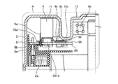
図1は、本発明の実施の形態1のDCブラシレスモータ201の部分断面図である。まず、図1を用いてDCブラシレスモータ201の全体構成を説明する。
Embodiment 1 FIG.
FIG. 1 is a partial cross-sectional view of a DC
実施の形態1のDCブラシレスモータ201は、熱伝導性材料である金属製の筒状フレーム1と、筒状フレーム1の胴部内に装着され、コイル2aを備えたステータ2と、ステータ2に立設されコイル2aの端部に接続された出力ピン5と、回転軸を中心として回転自在に配置されたロータ6と、駆動回路を構成する電子部品101が実装され出力ピン5と接続された回路基板8と、電子部品と熱的に接触されたヒートシンク9と、ヒートシンク9に熱的に接触されるとともに筒状フレーム1の開口部1oを塞ぐ熱伝導性材料である金属製のモ−タカバー12とを備える。ヒートシンク9は、回路基板8に熱的に接続される基板接続端子9aを備える。
The DC
さらに、コイル2aを絶縁保護する負荷側のインシュレータ3と同じく反負荷側のインシュレータ4とを有する。また、ヒートシンク9は、基板接続端子9aを有し、シャフト6cを囲むア−チ状を形成し、基板側は、圧縮変形する放熱シート10を介して回路基板8上の電子部品101に当接している。また、筒状フレーム1の開口部1oを塞ぐモータカバー12を備えており、モータカバー12は、軸受保持部12aを有し、高熱伝導体11を介してヒートシンク9に接触する。尚、モータカバー12の中央部にはリード端子取出し用の穴が形成されているが、図示しない端子台で塞がれるため、シール構造を維持することができるようになっている。高熱伝導体とは熱伝導性の高い材料であり、金属あるいは熱伝導性樹脂をはじめとする熱伝導性材料を用いることができる。
Further, it has an
ロータ6は、シャフト6cを中心にステータ2の内側に回転自在に配置される。この時、負荷側の軸受6aは筒状フレーム1に保持される。一方、反負荷側の軸受6bはモータカバー12に形成された軸受保持部12aに保持される。尚、軸受保持部12aをモータカバー12に形成したのは、強度確保の為である。高出力のモータになるほどロータのサイズおよび重量は大きくなる為、強固な保持機構が必要となる可能性が高い。
The
基板ケース7は、ステータ2の後から筒状フレーム1に挿入される。この時、貫通孔7aを挿通した出力ピン5は、基板ケース7における回路基板8の搭載面側に突き出し、回路基板8とはんだ付けにより電気的に接続される。尚、DCブラシレスモータ201は、民生用で良く用いられる3相駆動モータとする。この場合、出力ピン5は、U相用とV相用と、W相用との3個設けられる。また、基板ケース7の開口部7bおよび回路基板の開口部8aの径は、ロータ6を挿通できるように反負荷側の軸受6bの径よりも大きく開口されている。尚、基板ケース7は、反負荷側のインシュレータ4に当接させることにより、軸方向に位置決めされる。
The
筒状フレーム1およびモータカバー12の開口端外周部にはフレームフランジ1aおよびカバーフランジ12bが形成されている。モータカバー12を筒状フレーム1に外嵌し、カバーフランジ12bをフレームフランジ1aに当接させてネジ締付することにより、筒状フレーム1の開口部1oを塞ぐ。尚、モータカバー12とヒートシンク9は高熱伝導体11を介して熱接触されている。モータカバー12とヒートシンク9の熱的接触を介在する高熱伝導体11については、シリコン系あるいはエポキシ樹脂系をはじめとする接着剤が考えられる。実施の形態1ではモータカバー12とヒートシンク9の間に高熱伝導体11を介在させているが、ネジ締付をはじめとする直接接触させる接合手段を用いてモータカバー12とヒートシンク9を接合しても良い。
A
図2は、図1のA部拡大図である。また、図3は、図1におけるヒートシンクが接続された状態の回路基板の上面視図である。以下、図2および図3を用いて実施の形態1における放熱構造の詳細を説明する。 FIG. 2 is an enlarged view of a portion A in FIG. FIG. 3 is a top view of the circuit board in a state where the heat sink in FIG. 1 is connected. Hereinafter, the details of the heat dissipation structure in the first embodiment will be described with reference to FIGS. 2 and 3.
回路基板8に実装された各種の電子部品101は、駆動部101a、制御部101b、電源部101cをはじめとする各機能を構成する。駆動部101aには、ワンチップインバ−タIC(Integrated Circuit:集積回路)またはIGBT(Insulated Gate Bipolar Transistor:絶縁ゲートバイポーラトランジスタ)をはじめとするディスクリ−ト素子を6個とモータドライバICを組合せた三相ブリッジドライバを用いた構成が考えられる。また、制御部101bには、マイコンあるいはPLC(Programable Logic Controler)をはじめとする制御素子を用いた構成が考えられる。また、電源部101cには、外部電源と接続する電源端子が搭載される。さらに、EMC(Electro Magnetic Compatibility: 電磁両立性)フィルタ−および外部電源が交流電源である場合はAC−DCコンバ−タを用いた構成が考えられる。
The various
外部電源を電源部101cへ供給すると、駆動部101aは制御部101bからの制御指令によりコイル2aに通電し駆動することで、シャフト6cに負荷が接続されたロータ6を回転させる為の駆動トルクを発生させる。この時、回路基板8における主な発熱部品は駆動部101aおよび電源部101cを構成する部品となる。以下、実施の形態1では、駆動部101aにおける発熱部品101dを放熱対象として説明する。
When an external power supply is supplied to the
発熱部品101dは、図2に示すように、回路基板8に実装され、上面を放熱シート10を介してヒートシンク9に接続され、さらにヒートシンク9は高熱伝導体11を介してモータカバー12に当接している。このため、発熱部品101dの放熱は、放熱シート10とヒートシンク9と高熱伝導体11を介して接触されたモータカバー12を用いた伝熱により行われる。放熱シート10は、発熱部品101dとヒートシンク9との熱伝導性を向上させる他、圧縮変形する特性により、軸方向の組立て誤差による発熱部品101dおよび回路基板8全体への応力を緩和する。
As shown in FIG. 2, the
尚、上記応力に対する圧縮変形する特性を持つ部材として、図4に実施の形態1のDCブラシレスモータの変形例の要部拡大図を示すように基板ケース7にバネ性を有する基板支持部7cを設けることも考えられる。バネ性を有する基板支持部7cは、ヒートシンク9の取付けにより発熱部品101dおよび回路基板8全体にかかる圧力に対して、弾性の法則によりバネの反力を発揮する。応力とバネの反力とが拮抗するように構造設計を行うことで、放熱シート10を無くすか、放熱シート10の代わりに高熱伝導体11を介在させる構成とすることが可能となる。以上のように、放熱シート10に代えて高熱伝導体11を介在させることでコスト低減が可能となる。
As a member having the property of compressively deforming with respect to the stress, a
次に、ヒートシンク9は、軸受保持部12aを設けるのに伴い形成された絞り加工部12cおよび発熱部品101d以外の部品および出力ピン5との干渉を回避しつつモータカバー12との接触面積を大きくとる為、図3に示すように、軸方向から見てア−チ状つまりシャフト6cを囲むアーチ状を形成している。実施の形態1では、発熱部品101d以外の部品が電源部101cの部品である。尚、図3では円環の一部が欠けた形状を示しているが、多角形をはじめとする別の形状としても良い。また、基板接続端子9aは、ヒートシンク9と一体成型もしくはカシメあるいはネジ締付により接合されている。
Next, the
ヒートシンク9を放熱シート10に圧接すると、基板接続端子9aは、回路基板8上のスルーホール8bに挿入されるので、はんだ付けにて接続および固定する。接続方法には、高熱伝導性を持つ接続部を得ることのできる接続方法であれば他の導電接続手段あるいは接着材による機械的接続を用いても良い。
When the
図3では基板接続端子9aを3個としているが、要求される放熱性能、取付け安定性あるいは回路基板8上へのスルーホール8bの配置スペ−ス余裕を考慮して2個以下あるいは4個以上としても良い。放熱性能は、当然ながら基板接続端子9aの数が多いほど高い。さらに、基板接続端子9aの位置が発熱部品101dに近いほど、伝熱効果は高くなる。
In FIG. 3, the number of the
実施の形態1の構成をとることで、基板接続端子9aを介して回路基板8とヒートシンク9とが接続されるため、簡単な構成および製造方法で発熱部品101d→ヒートシンク9→モータカバー12の伝熱経路に加え、発熱部品101d→回路基板8→ヒートシンク9→モータカバー12の伝熱経路が得られる。これにより、材料および製造コストを低く抑えながらDCブラシレスモータ201に必要な放熱性能を確保することができる。
By adopting the configuration of the first embodiment, the
実施の形態2.
上述した放熱構造の放熱性能をさらに向上させたい場合は、回路基板8とヒートシンク9との間の熱抵抗を下げれば良い。以下、実施の形態2では、図5および図6を用いて前述の熱抵抗を低減する構成を提示する。図5は、実施の形態2のDCブラシレスモータの部分断面図、図6は、実施の形態2のDCブラシレスモータにおけるヒートシンクが接続された状態の回路基板の上面視図である。実施の形態2のDCブラシレスモータで用いられる回路基板8は、基板接続端子9aによりヒートシンク9との熱伝導性を高めるために、基板接続端子9aに熱接触するように、回路パターンと同一材料を用いて同一工程でパターニングされる放熱用のベタパターンを形成している。
In order to further improve the heat radiation performance of the above-described heat radiation structure, the thermal resistance between the
まず、図5および図6に示す構成を説明する。図5は、図2におけるヒートシンク9が回路基板8の接触面9cを有し、熱接触性を高めた構成である。回路基板8には、ヒートシンク9との接触面8cを包含する第1ベタパターン8dと、第1ベタパターン形成面である第1主面8Aの反対面である第2主面8Bに形成されたベタパターン8eが形成され、放熱シート10aは発熱する発熱部品101dおよび接触面8cを包含するように形成されている。また、図6は、図5におけるヒートシンク9が接続された状態の回路基板8の上面視図である。第1ベタパターン8dは、スルーホール8bと結合されている。
First, the configuration shown in FIGS. 5 and 6 will be described. FIG. 5 shows a configuration in which the
図5および図6に示す構成によれば、ヒートシンク9が接触面9cにて、熱伝導性の良い第1ベタパターン8dと放熱シート10aを介して回路基板8に接触するので、ヒートシンク9と回路基板8の間の熱抵抗を低減できる。図6ではヒートシンク9の回路基板8との接触面9cおよび回路基板8上の接触面8cを包含する第1ベタパターン8dを2箇所としているが、要求される放熱性能あるいは回路基板8における第1ベタパターン8dの形成スペ−スの余裕を考慮して1箇所でも3箇所以上でも良い。
According to the configuration shown in FIGS. 5 and 6, the
放熱性能は、当然ながら接触面8cの数および面積が大きいほど高い。さらに、接触面8cの配置が発熱部品101dに近いほど、伝熱効果は高くなる。第1ベタパターン8dに関しては、発熱部品101dが発生させた熱を回路基板8上で拡散させるという効果を発揮するという観点からは、当然ながら面積は大きい方が良い。但し、電気用品安全法あるいはIEC規格(International Electrotechnical Commission:IEC)への適合のための沿面距離確保、外来ノイズおよび雷サ−ジをはじめとする種々の原因による故障および誤動作防止のための対ア−ス電位間距離確保といった制約がある。
The heat radiation performance is naturally higher as the number and area of the contact surfaces 8c are larger. Further, as the arrangement of the
従って、電子部品101、出力ピン5、あるいはパターン配線が無いスペ−ス全体をベタパターンとするのは困難である。また、基板接続端子9aがはんだ付けされたスルーホール8bと第1ベタパターン8dを結合させたことにより、ヒートシンク9と回路基板8との間の熱抵抗を低減できる。図5に示すように、第1ベタパターン8d形成面の反対面に形成されたベタパターン8eを同様にスルーホール8bと結合させると、さらに熱抵抗を低減できる。尚、スルーホールとベタパターンの結合は、パターン設計によりコストアップ無しで実施できる。
Therefore, it is difficult to make the entire space without the
実施の形態3.
次に、図7から図9に示す構成を説明する。図7は、実施の形態3のDCブラシレスモータの部分断面図である。図7は、図2における回路基板8を多層基板で構成し、第2層基板8f、第3層基板8gの第2ベタパターン8h、第3ベタパターン8iがスルーホール8bと結合されている構成を示す図である。また、図8および図9は図7における多層基板の中間層の上面視図である。
Next, the configuration shown in FIGS. 7 to 9 will be described. FIG. 7 is a partial cross-sectional view of the DC brushless motor according to the third embodiment. FIG. 7 shows a configuration in which the
図7から図9に示した実施の形態3の構成によれば、基板接続端子9aがはんだ付けされたスルーホール8bと第2ベタパターン8hおよび第3ベタパターン8iを結合させたことにより、ヒートシンク9と回路基板8の間の熱抵抗を低減できる。尚、第2層基板8fと第3層基板8gの内、どちらかの層のみにベタパターンを形成する構成としても良い。第2ベタパターン8hおよび第3ベタパターン8iも図5および図6で示した構成におけるベタパターンと同様に面積は大きい方が良いが、上述した沿面距離あるいは対ア−ス電位間距離の制約がある為、電子部品101の端子、出力ピン5、パターン配線が無いスペ−ス全体をベタパターンとするのは困難である。尚、実施の形態3では4層基板を例に挙げているが、さらに多層化してスルーホール8bと結合されるベタパターンを有する基板層数を増やせば、熱抵抗がより低減できるのは言うまでもない。但し、層数を増やすほど基板コストが増大するので、放熱性能とコストのバランスを考える必要がある。
According to the configuration of the third embodiment shown in FIGS. 7 to 9, the through
以上により、図5から図9に示した実施の形態2および3のDCブラシレスモータによれば、材料コストの高騰を抑え、構成および製造方法を複雑化せず回路基板8とヒートシンク9との間の熱抵抗を低減できるので、低コストで放熱性能をさらに向上させることができる。 As described above, according to the DC brushless motors of the second and third embodiments shown in FIGS. 5 to 9, the rise in material cost is suppressed, and the structure and the manufacturing method are not complicated. Can be reduced, so that the heat radiation performance can be further improved at low cost.
尚、実施の形態1から3で説明した放熱用のスルーホール8bは電位をフロ−ティングとしても問題ないが、特定の電位に接続するならばGND電位が望ましい。GND電位は駆動部101aおよび制御部101bを駆動する為の各種DC電源の基準電位であり、ベタパターンと接続することで各種ノイズ対策効果を発揮する。
The through
実施の形態4.
実施の形態4のDCブラシレスモータについて説明する。図10は、実施の形態4のDCブラシレスモータの部分断面図、図11は、図10のB部拡大図、図12は、実施の形態4のヒートシンクが接続された回路基板の上面視図である。まず、図10を用いてDCブラシレスモータ301の全体構成を説明する。尚、実施の形態1と同じ構成の部位については説明を省略するが同一部位には同一符号を付した。
A DC brushless motor according to a fourth embodiment will be described. 10 is a partial sectional view of the DC brushless motor according to the fourth embodiment, FIG. 11 is an enlarged view of a portion B in FIG. 10, and FIG. 12 is a top view of a circuit board to which the heat sink according to the fourth embodiment is connected. is there. First, the overall configuration of the
実施の形態4では、基板ケース307および回路基板308の中央に開口部を設けていない。基板ケース307には負荷側に軸受保持部307bが設けられ、反負荷側の軸受6bを保持する。これに伴い基板ケース307の負荷側に絞り加工部307cが形成される。
In the fourth embodiment, an opening is not provided at the center of the
実施の形態4では、軸受保持部307bが基板ケース307に設けられたことにより、カバー312は、軸受保持部および絞り加工部が無い。カバーフランジ312aは、実施の形態1と同様のものを有する。
In the fourth embodiment, the
実施の形態4においては、貫通孔307aを防湿シール材313で塞ぐことにより、回路基板308の設置空間が外気から遮断されるので耐湿性を向上させることができる。
In the fourth embodiment, by covering the through-
図11は、図10のB部拡大図である。また、図12は、図11におけるヒートシンクが接続された状態の回路基板の上面視図である。以下、図11および図12を用いて実施の形態4における放熱構造の詳細を説明する。尚、実施の形態2と同じ構成の部位については説明を省略する。同一部位に同一符号を付した。 FIG. 11 is an enlarged view of a portion B in FIG. FIG. 12 is a top view of the circuit board in a state where the heat sink in FIG. 11 is connected. Hereinafter, the details of the heat dissipation structure according to the fourth embodiment will be described with reference to FIGS. 11 and 12. The description of the same components as those in the second embodiment is omitted. The same parts have the same reference numerals.
ヒートシンク309は、モータカバー312に絞り加工部が無いことから、発熱部品101d以外の部品および出力ピン5との干渉を回避しつつモータカバー312との接触面積を大きくとることができる。実施の形態4では、発熱部品101d以外の部品は、電源部101cの部品に相当する。尚、図12では円筒の一部が欠けた形状を示しているが、多角形をはじめとする別の形状を用いても良い。また、基板接続端子309aは、実施の形態1と同様のものを有し、ヒートシンク309と一体成型もしくはカシメあるいはネジ締付をはじめとする各種接合方法により接合されている。
Since the
以上のような構造とすることで、実施の形態2のDCブラシレスモータにおいても基板接続端子309aを介して回路基板308とヒートシンク309との接続がなされており、簡単な構成および製造方法で発熱部品101d→ヒートシンク309→モータカバー312の伝熱経路に加え、発熱部品101d→回路基板308→ヒートシンク309→モータカバー312の伝熱経路が得られる。これにより、材料コストおよび製造コストを低く抑えながらDCブラシレスモータ301においても必要な放熱性能を確保することができる。
With the above-described structure, the
また、図5から図9を用いて実施の形態2と実施の形態3で説明した熱抵抗の低減策は実施の形態1と同様に適用できる。これにより、DCブラシレスモータのコストの高騰を抑制し、構成あるいは製造方法を複雑化せず回路基板308とヒートシンク309との間の熱抵抗を低減できるので、低コストで放熱性能をさらに向上させることができる。
The measures for reducing the thermal resistance described in the second and third embodiments with reference to FIGS. 5 to 9 can be applied similarly to the first embodiment. As a result, a rise in the cost of the DC brushless motor can be suppressed, and the thermal resistance between the
実施の形態5.
実施の形態1から4で説明した放熱構造を有するDCブラシレスモータは、低コスト且つ高い生産性を求められる換気送風機をはじめとするシステムに適している。そこで、実施の形態5では、実施の形態1から4で説明したDCブラシレスモータの換気送風機への搭載例について説明する。
The DC brushless motor having the heat dissipation structure described in the first to fourth embodiments is suitable for a system such as a ventilation blower that requires low cost and high productivity. Therefore, in a fifth embodiment, an example will be described in which the DC brushless motor described in the first to fourth embodiments is mounted on a ventilation blower.
図13は、実施の形態1から4のDCブラシレスモータを搭載した換気扇の断面図である。換気扇401の筐体402には実施の形態1から4のDCブラシレスモータ201または301が搭載され、シャフト6cには送風ファン403が取付けられている。筐体402は天井板404に埋込設置された後、グリル405が下から取付けられる。
FIG. 13 is a cross-sectional view of a ventilation fan equipped with the DC brushless motor according to the first to fourth embodiments. The
DCブラシレスモータ201または301を通電駆動すると、駆動トルクが発生し送風ファン403を回転させる。送風ファン403が回転すると、図13に矢印で示した空気の流れが発生する。前述したフレームフランジとカバーフランジのネジ締付により、DCブラシレスモータ201または301は筐体402と当接する。そのことにより、通電駆動による発熱を筐体402へ伝熱するので放熱効果が得られる。
When the
実施の形態4のDCブラシレスモータ301の場合、回路部406とモータ部407は、前述したように防湿処理された基板ケース307で仕切られている。これにより、回路部406に湿気が入りにくい構造となっているため、例えば浴室をはじめとする高温高湿環境でも換気扇401を使用することができる。
In the case of the
以上のように、実施の形態5におけるDCブラシレスモータを搭載した換気扇は、実施の形態1から4で説明した放熱効果が得られる。また、DCブラシレスモータの搭載により、低コストで換気扇の省エネルギー化、小型化が実現できる。また、実施の形態4のDCブラシレスモータを搭載した場合は、耐湿性を向上させることもできる。 As described above, the ventilation fan equipped with the DC brushless motor according to the fifth embodiment has the heat radiation effect described in the first to fourth embodiments. Further, by installing a DC brushless motor, energy saving and downsizing of the ventilation fan can be realized at low cost. When the DC brushless motor according to the fourth embodiment is mounted, the moisture resistance can be improved.
尚、前記実施の形態では、金属製のモータカバーを用いたが、金属製に限定されることなく、熱伝導性樹脂をはじめとする熱伝導性材料製であればよい。 In the above-described embodiment, the motor cover made of metal is used. However, the motor cover is not limited to metal, and may be made of a heat conductive material such as a heat conductive resin.
以上の実施の形態に示した構成は、本発明の内容の一例を示すものであり、別の公知の技術と組み合わせることも可能であるし、本発明の要旨を逸脱しない範囲で、構成の一部を省略および変更することも可能である。 The configurations described in the above embodiments are merely examples of the contents of the present invention, and can be combined with other known technologies, and can be combined with other known technologies without departing from the gist of the present invention. It is also possible to omit and change parts.
1 筒状フレーム、1a フレームフランジ、1o 開口部、2 ステ−タ、2a コイル、3 負荷側のインシュレータ、4 反負荷側のインシュレータ、5 出力ピン、6 ロータ、6a 負荷側の軸受、6b 反負荷側の軸受、6c シャフト、7 基板ケース、7a 貫通孔、7b 開口部、7c 基板支持部、8 回路基板、8a 開口部、8b スルーホール、8c 接触面、8A 第1主面、8d 第1ベタパターン、8B 第2主面、8e 第1ベタパターン形成面の反対面に形成されたベタパターン、8f 第2層基板、8g 第3層基板、8h 第2ベタパターン、8i 第3ベタパターン、9 ヒートシンク、9a 基板接続端子、9c 接触面、10 放熱シート、10a 放熱シート、11 高熱伝導体、12 モータカバー、12a 軸受保持部、12b カバーフランジ、12c 絞り加工部、101 電子部品、101a 駆動部、101b 制御部、101c 電源部、101d 発熱部品、201 DCブラシレスモータ、301 DCブラシレスモータ、307 基板ケース、307a 貫通孔、307b 軸受保持部、307c 絞り加工部、308 回路基板、309 ヒートシンク、309a 基板接続端子、312 モータカバー、312a カバーフランジ、313 防湿シール材、401 換気扇、402 筐体、403 送風ファン、404 天井板、405 グリル、406 回路部、407 モータ部。 Reference Signs List 1 cylindrical frame, 1a frame flange, 1o opening, 2 stator, 2a coil, 3 load side insulator, 4 counter load side insulator, 5 output pin, 6 rotor, 6a load side bearing, 6b counter load Side bearing, 6c shaft, 7 substrate case, 7a through hole, 7b opening, 7c substrate support, 8 circuit board, 8a opening, 8b through hole, 8c contact surface, 8A first main surface, 8d first solid Pattern, 8B second main surface, 8e solid pattern formed on the opposite surface of the first solid pattern forming surface, 8f second layer substrate, 8g third layer substrate, 8h second solid pattern, 8i third solid pattern, 9 Heat sink, 9a Board connection terminal, 9c Contact surface, 10 heat dissipation sheet, 10a heat dissipation sheet, 11 high thermal conductor, 12 motor cover, 12a shaft Holding unit, 12b cover flange, 12c drawing unit, 101 electronic components, 101a driving unit, 101b control unit, 101c power supply unit, 101d heating component, 201 DC brushless motor, 301 DC brushless motor, 307 board case, 307a through hole, 307b bearing holding portion, 307c drawing portion, 308 circuit board, 309 heat sink, 309a board connection terminal, 312 motor cover, 312a cover flange, 313 moisture-proof sealing material, 401 ventilation fan, 402 housing, 403 blower fan, 404 ceiling plate, 405 grill, 406 circuit unit, 407 motor unit.
Claims (13)
前記筒状フレームの胴部内に装着され、コイルを備えたステータと、
回転軸を中心として回転自在に配置されたロータと、
発熱部品を含む複数の電子部品が搭載され、前記ステータの前記コイルと接続された回路基板と、
前記発熱部品と接触する第1の領域と、前記回路基板と接触する前記第1の領域と異なる第2の領域とを有するヒートシンクと、
一方の面が前記ヒートシンクと接触され、他方の面が前記発熱部品および前記回路基板と接触される放熱シートと、
前記ヒートシンクに熱的に接触するとともに前記筒状フレームの第1の開口部を塞ぐ熱伝導性材料で構成されたモータカバーと、
一端側が前記ヒートシンクに接触され、他端側が前記回路基板における前記発熱部品が搭載される第3の領域および前記第2の領域に対応する第4の領域と異なる第5の領域で接触される基板接続端子と、を有し、
前記放熱シートは、前記発熱部品と前記ヒートシンクの前記第1の領域との間に介在され、かつ前記ヒートシンクの前記第2の領域と前記回路基板の前記第4の領域との間に介在されることを特徴とするDCブラシレスモータ。 A cylindrical frame made of a heat conductive material,
A stator mounted in the body of the cylindrical frame and provided with a coil,
A rotor arranged rotatably about a rotation axis,
A plurality of electronic components including a heat generating component is mounted, and a circuit board connected to the coil of the stator,
A heat sink having a first region in contact with the heat-generating component and a second region different from the first region in contact with the circuit board ;
A heat dissipation sheet having one surface in contact with the heat sink and the other surface in contact with the heat generating component and the circuit board;
A motor cover made of a heat conductive material that thermally contacts the heat sink and closes the first opening of the cylindrical frame ;
A substrate having one end contacting the heat sink and the other end contacting a fifth region of the circuit board which is different from a third region on which the heat-generating component is mounted and a fourth region corresponding to the second region; has a connection terminal, a,
The heat dissipation sheet is interposed between the heat generating component and the first area of the heat sink, and is interposed between the second area of the heat sink and the fourth area of the circuit board. DC brushless motor characterized by the above-mentioned.
前記ステータは前記筒状フレームの胴部内に嵌合されており、
前記回路基板には、絶縁材料製の基板ケースが装着されたことを特徴とする請求項1から4のいずれか1項に記載のDCブラシレスモータ。 The tubular frame and the motor cover are made of metal,
The stator is fitted in the body of the tubular frame,
The DC brushless motor according to any one of claims 1 to 4, wherein a board case made of an insulating material is mounted on the circuit board.
前記モータカバーは軸受保持部を有し、前記第2の開口部に挿通されたロータの反負荷側の軸受は前記モータカバーの前記軸受保持部に保持されたことを特徴とする請求項5に記載のDCブラシレスモータ。 The board case and the circuit board have a second opening at the center where the rotor is inserted,
6. The motor cover according to claim 5 , wherein the motor cover has a bearing holding portion, and the bearing on the non-load side of the rotor inserted into the second opening is held by the bearing holding portion of the motor cover. The DC brushless motor as described.
前記ロータの反負荷側の軸受は前記基板ケースの前記軸受保持部に保持されたことを特徴とする請求項5に記載のDCブラシレスモータ。 The board case has a bearing holding part whose shape is processed on a load side,
The DC brushless motor according to claim 5 , wherein the bearing on the non-load side of the rotor is held by the bearing holding portion of the board case.
前記基板ケースは前記出力ピンが挿通される貫通孔を有し、
前記出力ピンが挿通される前記基板ケースの前記貫通孔は防湿シール材で塞がれたことを特徴とする請求項5に記載のDCブラシレスモータ。 The coil of the stator and the circuit board are connected by an output pin erected on the stator,
The board case has a through hole through which the output pin is inserted,
The DC brushless motor according to claim 5 , wherein the through-hole of the board case through which the output pin is inserted is closed with a moisture-proof seal material.
前記基板接続端子は前記スルーホールに挿入されていることを特徴とする請求項2または3に記載のDCブラシレスモータ。 The circuit board has a through hole coupled to the second solid pattern,
DC brushless motors are pre Kimoto plate connecting terminal according to 請 Motomeko 2 or 3 shall be the feature that you have been inserted into the through hole.
前記第2のベタパターンは、前記多層配線基板の中間層に形成されていることを特徴とする請求項2または3に記載のDCブラシレスモータ。 The circuit board is a multi-layer wiring board,
Said second solid pattern, DC brushless motor according to claim 2 or 3, characterized in that it is formed in the intermediate layer of the multilayer wiring board.
Priority Applications (1)
| Application Number | Priority Date | Filing Date | Title |
|---|---|---|---|
| JP2016122111A JP6647152B2 (en) | 2016-06-20 | 2016-06-20 | DC brushless motor and ventilation blower |
Applications Claiming Priority (1)
| Application Number | Priority Date | Filing Date | Title |
|---|---|---|---|
| JP2016122111A JP6647152B2 (en) | 2016-06-20 | 2016-06-20 | DC brushless motor and ventilation blower |
Publications (3)
| Publication Number | Publication Date |
|---|---|
| JP2017229124A JP2017229124A (en) | 2017-12-28 |
| JP2017229124A5 JP2017229124A5 (en) | 2018-10-11 |
| JP6647152B2 true JP6647152B2 (en) | 2020-02-14 |
Family
ID=60889375
Family Applications (1)
| Application Number | Title | Priority Date | Filing Date |
|---|---|---|---|
| JP2016122111A Active JP6647152B2 (en) | 2016-06-20 | 2016-06-20 | DC brushless motor and ventilation blower |
Country Status (1)
| Country | Link |
|---|---|
| JP (1) | JP6647152B2 (en) |
Families Citing this family (5)
| Publication number | Priority date | Publication date | Assignee | Title |
|---|---|---|---|---|
| JP2019180194A (en) | 2018-03-30 | 2019-10-17 | 日本電産サーボ株式会社 | motor |
| JP7047613B2 (en) * | 2018-06-08 | 2022-04-05 | 株式会社デンソー | Control device integrated rotary electric machine |
| JP7539106B2 (en) | 2020-03-26 | 2024-08-23 | パナソニックIpマネジメント株式会社 | Brushless motors and power tools |
| JP7473459B2 (en) | 2020-11-19 | 2024-04-23 | ニデックインスツルメンツ株式会社 | Pumping equipment |
| JP7515705B2 (en) | 2021-04-26 | 2024-07-12 | 三菱電機株式会社 | Rotating Electric Machine |
Family Cites Families (5)
| Publication number | Priority date | Publication date | Assignee | Title |
|---|---|---|---|---|
| JP2002151634A (en) * | 2000-11-08 | 2002-05-24 | Nissan Motor Co Ltd | Board radiator |
| JP2006353067A (en) * | 2005-06-20 | 2006-12-28 | Asmo Co Ltd | Control circuit unit for motor and manufacturing method therefor, and motor equipped with the control circuit unit for motor |
| JP5266768B2 (en) * | 2008-01-21 | 2013-08-21 | 株式会社ジェイテクト | Circuit board fixing structure of motor unit and motor unit having this circuit board fixing structure |
| JP5748698B2 (en) * | 2012-04-09 | 2015-07-15 | 三菱電機株式会社 | Electric motor |
| JP2015144532A (en) * | 2014-01-31 | 2015-08-06 | 株式会社富士通ゼネラル | Electric motor |
-
2016
- 2016-06-20 JP JP2016122111A patent/JP6647152B2/en active Active
Also Published As
| Publication number | Publication date |
|---|---|
| JP2017229124A (en) | 2017-12-28 |
Similar Documents
| Publication | Publication Date | Title |
|---|---|---|
| JP6647152B2 (en) | DC brushless motor and ventilation blower | |
| JP5907152B2 (en) | Drive device | |
| KR101748639B1 (en) | Power conversion apparatus | |
| JP4361486B2 (en) | Device structure for mounting electric power components and control electronic components for electric motors | |
| CN106067711B (en) | Motor drive control device for vehicle | |
| JP5649727B2 (en) | Drive unit-integrated rotating electrical machine | |
| JP6129286B1 (en) | Electric power supply unit integrated rotating electric machine | |
| JP5609289B2 (en) | Inverter integrated motor | |
| JP6505311B2 (en) | Motor and ventilation fan | |
| JP2017017975A (en) | Electric compressor | |
| JP6020379B2 (en) | Semiconductor device | |
| JP2015092803A (en) | Electric motor and electric pump | |
| JP6648569B2 (en) | Motor drive control device for vehicle | |
| CN111133572B (en) | Component assembly and electronic device | |
| CN110915111B (en) | Motor and ventilation fan | |
| JP6467478B1 (en) | Component mounting body and electronic equipment | |
| WO2016113858A1 (en) | Motor, and motor production method | |
| WO2022209766A1 (en) | Motor | |
| JP2012253845A (en) | Motor and ventilating fan | |
| WO2014203552A1 (en) | Power conversion device | |
| WO2017002693A1 (en) | Electric compressor | |
| JP6439834B2 (en) | Control device | |
| JP7134302B1 (en) | Rotating electric machine with integrated controller | |
| JP2014049610A (en) | Circuit board | |
| JP2014053373A (en) | Circuit board |
Legal Events
| Date | Code | Title | Description |
|---|---|---|---|
| A521 | Request for written amendment filed |
Free format text: JAPANESE INTERMEDIATE CODE: A523 Effective date: 20180830 |
|
| A621 | Written request for application examination |
Free format text: JAPANESE INTERMEDIATE CODE: A621 Effective date: 20180830 |
|
| A131 | Notification of reasons for refusal |
Free format text: JAPANESE INTERMEDIATE CODE: A131 Effective date: 20190604 |
|
| A977 | Report on retrieval |
Free format text: JAPANESE INTERMEDIATE CODE: A971007 Effective date: 20190531 |
|
| A521 | Request for written amendment filed |
Free format text: JAPANESE INTERMEDIATE CODE: A523 Effective date: 20190731 |
|
| TRDD | Decision of grant or rejection written | ||
| A01 | Written decision to grant a patent or to grant a registration (utility model) |
Free format text: JAPANESE INTERMEDIATE CODE: A01 Effective date: 20191217 |
|
| A61 | First payment of annual fees (during grant procedure) |
Free format text: JAPANESE INTERMEDIATE CODE: A61 Effective date: 20200114 |
|
| R150 | Certificate of patent or registration of utility model |
Ref document number: 6647152 Country of ref document: JP Free format text: JAPANESE INTERMEDIATE CODE: R150 |
|
| R250 | Receipt of annual fees |
Free format text: JAPANESE INTERMEDIATE CODE: R250 |
|
| R250 | Receipt of annual fees |
Free format text: JAPANESE INTERMEDIATE CODE: R250 |