JP5591069B2 - Coordinate input device, control method therefor, and program - Google Patents
Coordinate input device, control method therefor, and program Download PDFInfo
- Publication number
- JP5591069B2 JP5591069B2 JP2010247838A JP2010247838A JP5591069B2 JP 5591069 B2 JP5591069 B2 JP 5591069B2 JP 2010247838 A JP2010247838 A JP 2010247838A JP 2010247838 A JP2010247838 A JP 2010247838A JP 5591069 B2 JP5591069 B2 JP 5591069B2
- Authority
- JP
- Japan
- Prior art keywords
- light
- sensor means
- unit
- coordinate input
- sensor
- Prior art date
- Legal status (The legal status is an assumption and is not a legal conclusion. Google has not performed a legal analysis and makes no representation as to the accuracy of the status listed.)
- Expired - Fee Related
Links
Images


Classifications
-
- G—PHYSICS
- G06—COMPUTING OR CALCULATING; COUNTING
- G06F—ELECTRIC DIGITAL DATA PROCESSING
- G06F3/00—Input arrangements for transferring data to be processed into a form capable of being handled by the computer; Output arrangements for transferring data from processing unit to output unit, e.g. interface arrangements
- G06F3/01—Input arrangements or combined input and output arrangements for interaction between user and computer
- G06F3/03—Arrangements for converting the position or the displacement of a member into a coded form
- G06F3/041—Digitisers, e.g. for touch screens or touch pads, characterised by the transducing means
- G06F3/042—Digitisers, e.g. for touch screens or touch pads, characterised by the transducing means by opto-electronic means
- G06F3/0421—Digitisers, e.g. for touch screens or touch pads, characterised by the transducing means by opto-electronic means by interrupting or reflecting a light beam, e.g. optical touch-screen
Landscapes
- Engineering & Computer Science (AREA)
- General Engineering & Computer Science (AREA)
- Theoretical Computer Science (AREA)
- Human Computer Interaction (AREA)
- Physics & Mathematics (AREA)
- General Physics & Mathematics (AREA)
- Position Input By Displaying (AREA)
Description
本発明は、情報の入力や選択をするために指等の指示具によって座標入力面に入力された座標位置を光学的に検出する座標入力装置及びその制御方法、プログラムに関するものである。特に、着脱可能で、可搬性を有する座標入力装置及びその制御方法、プログラムに関するものである。 The present invention relates to a coordinate input device that optically detects a coordinate position input to a coordinate input surface by an indicator such as a finger for inputting and selecting information, a control method therefor, and a program. In particular, the present invention relates to a coordinate input device that is detachable and has portability, a control method thereof, and a program.
従来、この種の座標入力装置として、各種方式の座標入力装置(タッチパネルやデジタイザ)が提案、または製品化されている。例えば、特殊な器具等を用いずに、指で画面上をタッチすることで、PC(パーソナルコンピュータ)等の情報処理装置の操作を簡単に行うことがきるタッチパネル等の座標入力装置が広く用いられている。 Conventionally, various types of coordinate input devices (touch panels and digitizers) have been proposed or commercialized as this type of coordinate input device. For example, a coordinate input device such as a touch panel that can easily operate an information processing device such as a PC (personal computer) by touching the screen with a finger without using a special instrument is widely used. ing.
その座標入力方式としては、抵抗膜を用いたもの、または、超音波を用いたもの等、種々のものがある。光を用いる座標入力方式ものとして、座標入力面外側に再帰反射材を設け、投光部からの光を再帰反射材で反射し、その光量分布を受光部により検出する方式が知られている。そして、この方式では、座標入力領域内を指等の指示具で指示することによってこの光路を遮り、遮光された方向を検知することで、指示位置を算出する(例えば、特許文献1、2参照)。
There are various coordinate input methods, such as those using a resistive film or those using ultrasonic waves. As a coordinate input method using light, a method is known in which a retroreflective material is provided outside the coordinate input surface, the light from the light projecting unit is reflected by the retroreflective material, and the light quantity distribution is detected by the light receiving unit. In this method, the optical path is interrupted by instructing the coordinate input area with an indicator such as a finger, and the indicated position is calculated by detecting the light-shielded direction (see, for example,
特許文献1の構成を一般化した例として、図10の構成を示す。図10は、座標入力面の両端に配置されたセンサユニット1L、1Rと、座標を入力する際に使用する座標入力面である所の座標入力有効領域3が示される。そして、座標入力有効領域3の三方を取り囲み、進入してきた光を進入してきた方向に再帰的に反射する再帰反射部4とを有している。
As an example in which the configuration of
センサユニット1L、1Rは、投光部及び受光部(不図示)を有している。投光部は、座標入力有効領域3の入力面にほぼ平行に扇形に広がる光を照射し、受光部は、その光が再帰反射部4で再帰反射され、戻ってきた光を受光する。座標入力装置は、2つのセンサユニット1L、1Rでそれぞれ検知された光の遮蔽方向(遮蔽角度θL、θR)と当該センサユニット1L及び1R間の距離に基づいて、座標入力有効領域3に入力された座標位置を算出することができる。尚、図10において、2はセンサユニット1L及び1Rを制御し、取得したセンサユニット1L及び1Rの出力信号を処理し、あるいはその処理結果を外部装置に出力する制御回路であり、8は再帰反射部4を保護するための光透過性の保護部材である。
Each of the
特許文献2には、特許文献1で示される光学遮光方式の座標入力装置におけるセンサユニット中の投光部及び受光部の具体的な構成の一例が示されている。
Patent Document 2 shows an example of a specific configuration of a light projecting unit and a light receiving unit in a sensor unit in the optical light shielding type coordinate input device shown in
特許文献3には、特許文献1、2に示される再帰反射部の代わりに、座標入力有効領域の周囲3辺に設けられ、導光方向と略垂直な側面に光を放出する導光部が示されている。
In
さらには、特許文献4には、各々のセンサユニットにおける発光部の点灯を制御する構成が開示されている。具体的には、一方のセンサユニットの発光部から出射された光が他方のセンサユニットの受光部で外乱光として受光されることを防止するために、センサユニットの各発光部からの光の出射が交互に行われるように制御したものである。
Furthermore,
さらには、特許文献5には、座標入力有効領域の上辺及び下辺に再帰反射部を配置し、センサユニットが、再帰反射部と座標入力有効領域との間に隙間を設けて配置されている構成が示されている。 Furthermore, in Patent Document 5, retroreflective portions are arranged on the upper and lower sides of the coordinate input effective area, and the sensor unit is arranged with a gap between the retroreflective part and the coordinate input effective area. It is shown.
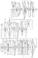
しかしながら、上記従来の先行技術に於いて、図11(A)に示すようなマルチディスプレイに対応する、言い換えれば、座標入力領域の大型化、横長化に対応することが、次の理由により困難となる。尚、図11(A)は、フロントプロジェクター3台を用いて一つの大型スクリーンに一つの画像として表示することを想定している
まず、第一に、従来技術による複数の座標入力装置を並べてマルチディスプレイ対応(図11(B)参照)とした場合、複数の座標入力装置のつなぎ目部分には再帰反射部4が必須となる。従って、表示画像が不連続となるばかりでなく、図11(B)における領域aから領域bへ連続して座標指示/操作をすることができず、操作性が大幅に低下する。つまり、マルチディスプレイにおいて、繋ぎ目部分の再帰反射部4は邪魔な構成要素となる。
However, in the conventional prior art described above, it is difficult to cope with the multi-display as shown in FIG. 11A, in other words, to cope with the increase in the size and the lateral length of the coordinate input area for the following reason. Become. In FIG. 11A, it is assumed that three front projectors are used to display one image on one large screen. First, a plurality of coordinate input devices according to the prior art are arranged side by side. In the case of display support (see FIG. 11B), the
その不具合を解消するためには、図11(A)に示すように、マルチディスプレイの表示領域外側に再帰反射部4を設けなければならない。図11(A)から明らかなように、図11(A)の方向aと図11(A)の方向bの距離差は、ディスプレイの面数が多くなればなるほど、大きくなる。従って、投光部で投光した光が再帰反射部4に到達し、再帰反射された光を受光部で検出するこの種の座標入力装置にあっては、この距離差(光路差)によって受光量の差が大きくなる。
In order to eliminate the problem, the
つまり、センサユニット1Lで投光され投光量が、投光方向に寄らず一定だったとしても、この距離差によって、方向aでは比較的大きな受光量を、方向bでは最も小さな受光量しか得られなくなる。この差を、受光素子(CCD、CMOS等の光電変換素子)のダイナミックレンジの範囲内に収めることは一般的には困難である。つまり、方向aの受光量をダイナミックレンジ範囲内の出力最大値になるように設定すれば、方向bの光を全く検知できない。あるいは方向bの光を検知できる程度に十分な投光を行えば、方向aからの光の検出信号が飽和してしまい、正しいデータを得ることが困難となる。
That is, even if the light projection amount emitted by the
その課題を解消するために、図11(A)の方向bへはより投光量を増大させたりして、投光方向に応じて投光量を変化させることが必要となる。そうすることで、受光する光量の平滑化が図られるが、コストアップ、装置が大きくなる等の弊害を避けることができない。 In order to solve the problem, it is necessary to increase the light projection amount in the direction b in FIG. 11A and change the light projection amount according to the light projection direction. By doing so, the amount of light received can be smoothed, but it is impossible to avoid problems such as an increase in cost and an increase in the size of the apparatus.
光路差を縮小する構成としては、図11(C)に示すように、より多くのセンサユニット1、1Rを配置して、一つ一つのセンサユニットが検出する領域を分割する構成が考えられる。この時、先に述べた操作性を低下させないと言う観点では、表示領域には再帰反射部4が無いのが好ましい形態であり、例えば、図11(C)に示すが如く、表示領域の上辺、及び下辺のみに再起反射部4を設けるものとする。センサユニット数は増加するが、光路差が小さくなり、安定した光信号を検出することが可能となる。
As a configuration for reducing the optical path difference, as shown in FIG. 11C, a configuration in which
特許文献5の構成は、表示領域の対向する2辺に再帰反射部を配置する構成であって、再帰反射部の外側に投光部及び受光部を設けている。この時、投受光と再帰反射部の座標入力面からの高さ(座標入力面の法線方向に対する高さ)が同一となると、再帰反射部が光路を遮ってしまう。そこで、投受光と再帰反射部の座標入力面からの高さ(座標入力面の法線方向に対する高さ)を異なる構成としているが、次のような新たな課題が生じている。 The configuration of Patent Document 5 is a configuration in which retroreflective portions are arranged on two opposite sides of a display area, and a light projecting portion and a light receiving portion are provided outside the retroreflective portion. At this time, if the height of the light projection / reception and the retroreflective portion from the coordinate input surface (the height of the coordinate input surface with respect to the normal direction) becomes the same, the retroreflective portion blocks the optical path. Therefore, the height of the light projection / reception and the retroreflective portion from the coordinate input surface (the height of the coordinate input surface with respect to the normal direction) is different, but the following new problem arises.
図12(A)に示すように、特許文献5の構成は再帰反射部903と座標入力面902との間に投光部及び受光部を有するセンサユニット901を配置している。センサユニット901中の投光部から投光された光は、対向する辺に設けられた再帰反射部903で再帰反射され、センサユニット901の受光部で受光される。従って、光路はハッチング部分908となる。仮に、指示具907を図示が如く配置すると、左側のセンサユニット901ではハッチング部分908の光路が遮られないので、左側のセンサユニット901では指示具907を検知できない。その一方で、右側のセンサユニット901のハッチング部分908の光路が指示具907が遮られるので、指示具907の位置情報(方向)を検出できる状態にある。
As shown in FIG. 12A, in the configuration of Patent Document 5, a
つまり、一方のセンサユニットでは位置情報(方向)を検知できても、他方のセンサユニットで位置情報(方向)を検知できないので、指示具907の状態では、指示具907の指示位置を算出することができない。指示位置を検出できるのは、指示具907が座標入力面902により近づき、左側のセンサユニット901の光路を十分に遮った時、言い換えれば、指示具907が座標入力面902をタッチする直前の位置に来た時と言える。従って、特許文献5の構成では、指示具907が座標入力面902より離れていると、その位置を安定して検出することができない。以後、座標入力面より離れた位置でも指示具907の位置を検出できる機能を『近接入力』と称する。
That is, even if the position information (direction) can be detected by one sensor unit, the position information (direction) cannot be detected by the other sensor unit. Therefore, in the state of the
この課題(領域によって近接入力ができない)に対応する構成として、図12(B)に示すように、センサユニット901の投光部と受光部の間に再帰反射部を設ける構成が考えられる。左側のセンサユニット901中の投光部910及び受光部909の間に再帰反射部903が設けられ、投光部910が対向する再帰反射部903に到達する光路と再帰反射部903から受光部909に到達する光路が図示が如く設定される。指示具907が図12(A)と同一の位置に有る場合、再帰反射部903から受光部909に到達する光路を遮ることは無いが、投光部910が対向する再帰反射部903に到達する光路を遮るので、この指示具907が検出可能となる。つまり、左右のセンサユニット901で検知でき、近接入力を可能とする構成となる。
As a configuration corresponding to this problem (proximity input cannot be performed depending on the area), a configuration in which a retroreflective portion is provided between the light projecting portion and the light receiving portion of the
図12(C)はセンサユニット901の断面状態を示し、この構成で効率良く再帰反射光を検出するためには、投光部910と受光部909間の距離Lが小さいのが好ましい。しかしながら、距離Lを小さくすると言うことは、再帰反射部903の幅hを小さくすることと等価であり、再帰反射部の幅hが小さくなった結果、再帰反射光は幅hにほぼ比例してその分小さくなる。
FIG. 12C shows a cross-sectional state of the
よって、再帰反射光を効率良く検出するためには、距離Lを小さくすることが好ましい構成であり、十分な再帰反射光を確保するためには、距離Lを大きくしなければならないと言う矛盾を解決しなければならない。 Therefore, in order to detect retroreflected light efficiently, it is preferable to reduce the distance L, and in order to ensure sufficient retroreflected light, there is a contradiction that the distance L must be increased. Must be resolved.
本発明は上記の課題を解決するためになされたものであり、入力位置によらず安定した座標入力が可能とする座標入力装置及びその制御方法、プログラムを提供することを目的とする。さらに、センサユニット近傍を含む座標入力有効領域全体において、近接入力を可能とする座標入力装置及びその制御方法、プログラムを提供することを目的とする。 The present invention has been made to solve the above problems, and an object of the present invention is to provide a coordinate input device, a control method therefor, and a program that enable stable coordinate input regardless of the input position. It is another object of the present invention to provide a coordinate input device, a control method therefor, and a program that enable proximity input in the entire coordinate input effective area including the vicinity of the sensor unit.
上記の目的を達成するための本発明による座標入力装置は以下の構成を備える。即ち、
矩形状の座標入力有効領域の対向する2辺に設けられた再帰反射部と、該2辺の各々に設けられた複数のセンサ手段とを有する座標入力装置であって、
前記センサ手段は、
到来する光を受光する受光部と、
前記2辺の内、対向する辺に設けられた再帰反射部に対して光を投光する投光部と
帯状の面から均一な拡散光を発光する面発光部とを備え、
前記センサ手段は、前記受光部によって、前記投光部で投光した光が前記対向する辺に設けられた前記再帰反射部によって再帰反射された光と、前記対向する辺に設けられた前記複数のセンサ手段の前記面発光部で発光した光を同時に検出する。
In order to achieve the above object, a coordinate input device according to the present invention comprises the following arrangement. That is,
A coordinate input device having a retroreflective portion provided on two opposite sides of a rectangular coordinate input effective area, and a plurality of sensor means provided on each of the two sides,
The sensor means includes
A light receiving unit for receiving incoming light;
Among the two sides, a light projecting unit that projects light to a retroreflective unit provided on the opposite side, and a surface light emitting unit that emits uniform diffused light from a band-shaped surface,
The sensor means includes the light reflected by the retroreflecting unit provided on the opposite side by the light projected by the light projecting unit by the light receiving unit, and the plurality of light provided on the opposing side. The light emitted from the surface light emitting portion of the sensor means is simultaneously detected.
以上説明したように、本発明によれば、入力位置によらず安定した座標入力が可能とし、センサユニット近傍を含む座標入力有効領域全体において、近接入力を可能とする座標入力装置及びその制御方法、プログラムを提供できる。 As described above, according to the present invention, a coordinate input device that enables stable coordinate input regardless of the input position and allows proximity input in the entire coordinate input effective region including the vicinity of the sensor unit and a control method thereof. Can provide programs.
以下、添付の図面を参照して、本発明をその好適な実施形態に基づいて詳細に説明する。尚、以下の実施形態において示す構成は一例に過ぎず、本発明は図示された構成に限定されるものではない。 Hereinafter, the present invention will be described in detail based on preferred embodiments with reference to the accompanying drawings. The configurations shown in the following embodiments are merely examples, and the present invention is not limited to the illustrated configurations.
<実施形態1>
図1は実施形態1の座標入力装置の概要を説明するための説明図である。
<
FIG. 1 is an explanatory diagram for explaining the outline of the coordinate input device according to the first embodiment.
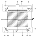
図1では、センサユニット1a〜1dが、矩形状の座標入力有効領域3の4隅近傍(角部近傍)に各々設けられている。センサユニット1a〜1dにはそれぞれ、投光部、受光部、及び面発光部が設けられている(詳細は後述)。座標入力有効領域3の対向する2辺には再帰反射部4a及び4bが設けられ、対向する一辺に設けられたセンサユニット1a及び1bあるいはセンサユニット1c及び1dの投光部で投光された光を再帰反射させる。
In FIG. 1,
再帰反射された再帰反射光は、センサユニット1a〜1dの受光部で検出される。受光部は、この再帰反射光を検出すると共に、対向する辺に設けられたセンサユニット1a及び1bあるいはセンサユニット1c及び1dの面発光部の光をも同時に検出するように構成されている。つまり、センサユニット1aの受光部で説明すれば、センサユニット1aの投光部の光が対向する辺に設けられた再帰反射部4bで再帰反射した光と、センサユニット1c及び1dの面発光部で発光した光を同時に検出する。また、センサユニット1aからみて、領域9a及び9bは面発光部の光と再帰反射光の検出の繋ぎ目部分となっている。繋ぎ目部分方向の光を確実に検出するために、その部分でのセンサユニットの面発光部と再帰反射部4はオーバーラップした構成となっている。センサユニット1bから見ても、領域9a及び9bの繋ぎ目部分は、オーバーラップした状態に設定される。
The retroreflected light retroreflected is detected by the light receiving portions of the
また、8a及び8bは、それぞれセンサユニット1a及び1b、及びセンサユニット1c及び1d、及び再帰反射部4a及び4bを収容する座標入力装置筐体であり、以後、センサバーと称する。尚、センサバー8aには、制御・演算ユニット2が更に収容されている。センサバー8a及び8b間は有線或いは無線等の通信部で信号送受信が行われ、制御・演算ユニット2は、センサユニット1a〜1dの投光部、受光部、及び面発光部を制御する。また、制御・演算ユニット2は各々のセンサユニット1a〜1dからの出力情報から指示位置を算出すると共に、その結果を外部装置(例えば、PC)に出力する。
尚、以下の説明において、センサユニット1a〜1dを総称する場合には、センサユニット1と表記する。同様に、再帰反射部4a及び4bを総称する場合には、再帰反射部4と表記する。
In the following description, the
<センサユニット1の説明>
図2は実施形態1のセンサユニット1の構造を説明する説明図である。
<Description of
FIG. 2 is an explanatory diagram illustrating the structure of the
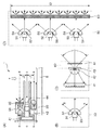
図2(A)はセンサユニット1の断面図であり、光学系を中心に説明する。5は座標入力行うための矩形状の座標入力面5であり、座標入力面5に近いほうから投光部30、受光部40、帯状の面発光部50が設けられている。投光部30の光学的中心線は、線分b−b、受光部40の光学的中心線は線分c−c、面発光部50の光学的中心線は線分d−dで示される。図示が如く、受光部40の光学的中心線である線分c−cから距離L1離れた位置に投光部30の光学的中心線である線分b−bが、距離L2離れた所に面発光部50の光学的中心線である線分d−dに設けられている。
FIG. 2A is a cross-sectional view of the
図2(B)〜(D)は、センサユニット1を正面(図2(A)の矢印の方向e)から見た正面図であり、図2(B)は投光部30、図2(C)は受光部40、図2(D)は面発光部50を説明する図である。
2 (B) to 2 (D) are front views of the
図2(B)において、31は赤外光を発する赤外LEDであり、発光した光は投光レンズ32によって、略90°範囲に光を投光する。一方、座標入力面5に対し水平方向(同2(A)参照)には、赤外LED31からの光は上下方向に制限された光束として投光され、主に、再帰反射部4に対して光が投光されるように構成されている。33は光透過性の接着剤であり、投光レンズ32及び赤外LED31の間を隙間無く充填されている。
In FIG. 2B,
図2(C)において、41は1次元のラインCCD、42は集光光学系として作用する受光レンズ、43は入射光の入射方向を制限する絞り、44は可視光等の余分な光の入射を防止する赤外フィルターである。投光部30で投光された光は、再帰反射部4によって再帰反射され、赤外フィルター44、絞り43を抜けて受光レンズ42によって、ラインCCD41の検出面上に集光される。
In FIG. 2C, 41 is a one-dimensional line CCD, 42 is a light-receiving lens that acts as a condensing optical system, 43 is a diaphragm that restricts the incident direction of incident light, and 44 is incident of extraneous light such as visible light. It is an infrared filter that prevents The light projected by the
実施形態1の場合、投光部30と受光部40とを重ねて配置しており、その距離L1は、再帰反射部4に対する観測角が小さくなるよう投光部30から再帰反射部4までの距離に比べて十分に小さな値に設定される。従って、距離L1を有していても十分な再帰反射光を受光部40で検知することが可能な構成となっている。
In the case of the first embodiment, the
また、正面から見て、絞り43の中心と投光部30の発光中心の位置は同じ位置に設定されている。従って、略90°方向に投光された投光部30の光は再帰反射部4によって再帰反射され、赤外フィルター44、絞り43を抜けて受光レンズ42によって、光の入射角に応じてラインCCD41の画素上に結像することになる。従って、ラインCCD41の出力信号は、反射光の入射角に応じた光量分布を出力することになるので、ラインCCD41の画素番号は角度情報を示すことになる。
Further, when viewed from the front, the position of the center of the
図2(D)は面発光部50の概略を説明する説明図であり、51、52及び53は赤外LED、54、55及び56はコリメートレンズ、57、58及び59は両者を接着する光透過性の接着剤である。60は拡散板であり、赤外LED51、52及び53で発光した光を拡散させ、拡散板60から拡散光を放射する。
FIG. 2D is an explanatory diagram for explaining the outline of the surface
実施形態1では、3個の赤外LED51、52及び53を用いているがこれに限定されるものではなく、拡散面からの発光が一様となるように、拡散板60の長さに応じてその個数が適宜設定される。
In the first embodiment, the three
また、発光面から一様に拡散光が放射されるならこの構成に限定されるものではなく、例えば、導光板を用いる方式であっても良い。ここで一様にと言う言葉を用いたが、更に説明を加える。詳細は後述するが、5図(A)に示す通りセンサユニット1aの受光部40は角度θaを視野範囲としている。従って、視野範囲θaの範囲で、対向する辺に設けられた再帰反射部4、及び面発光部50からの光を検出する。従って、図2(D)において、面発光部50の発光面長さL3の範囲で、満遍なく対向する辺に設けられたセンサユニット1に設けられた受光部40でその光が検出されなければならない。
In addition, the configuration is not limited to this configuration as long as diffused light is uniformly emitted from the light emitting surface. For example, a system using a light guide plate may be used. Here, the term “uniform” is used, but further explanation is added. Although details will be described later, as shown in FIG. 5A, the
今、図2(D)の面発光部50が図1のセンサユニット1aに設けられたものとする。ポイントSにおいて、対向する辺に設けられたセンサユニット1c及び1dの受光部40の方向が夫々M、Nであるとする。ポイントSにおいて発光した拡散光のうち、方向Mの光のみセンサユニット1cで、及び方向Nの光のみセンサユニット1dの受光部で検出される。従って、それ以外の方向に発光された拡散光は、座標入力装置にあっては無駄なエネルギーとして消費される。このように拡散光を発光する面発光部50を利用することで、光エネルギーのロスは有るものの、複雑な光学系を用いなくても、安価に発光面長さL3の範囲で必要な光を生成することができる。
Now, it is assumed that the surface
以上述べたとおり、面発光部50は対向する辺に設けられた少なくとも2つのセンサユニット1の受光部40へ、発光面長さL3の範囲で連続的に光を放射しなければならない。従って、センサユニット1a〜1dの各受光部40がその視野範囲で、面発光部50の発光面長さL3の範囲で連続的に光を検出できる程度の光強度を、以後、面発光部50が放射する『略均一な拡散光』と称する。
As described above, the surface
また、本願発明に有っては、例えば、投光部30の光学系を面発光部50の部品として利用し、部品共通化によるコスト削減効果を得ている。
Further, in the present invention, for example, the optical system of the
以上説明したように、受光部40が投光部30及び面発光部50に挟まれた構造となっている。そして、投光部30と受光部40の距離L1は、対向する再帰反射部4に対する観測角が小さくなるよう投光部30から対向する再帰反射部4までの距離に比べて十分に小さな値に設定される。同様に、面発光部50と受光部40の距離L2も十分に小さな値に設定されている。従って、受光部40を両者で挟む構造とすることで、受光部40は投光部30による再帰反射光、及び面発光部50の光を、両者共に効率良く検出することができる。
As described above, the
ここで、センサユニット1の受光部40が検出する信号について考察する。図1のセンサユニット1aについて着目して説明すると、投光部30で投光された光が再帰反射部4bで再帰反射され、受光部40で検出される再帰反射光の強度は主に以下の要因によって決まる。
Here, a signal detected by the
要因1:投光部30の投光分布
要因2:再帰反射部4bに入射する再帰反射効率の入射角特性
要因3:投光部30と再帰反射部4bまでの距離
要因4:受光部40の受光分布
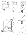
順に説明を加えると、図2(B)において、投光部30の主光線方向をfとすれば、一般的に方向fの光放射強度は強く、方向g、もしくは方向hの方向にずれることによって、図3(B)の如く光放射強度は低下する。
Factor 1: Light distribution of the
また、図3(A)において、再帰反射部4bの法線方向に対する光の到来方向を入射角αと定義すれば、再帰反射部4の再帰反射効率は図3(C)に示される通り、入射角0°で最大となり、入射角が大きくなると低下する。従って、図3(A)の方向Jでは再帰反射効率は良く、方向Kに行くに従って再帰反射効率が低下することになる。つまり、再帰反射部4bに到達した投光部30からの光は、その入射角に応じて再帰反射光の強度が決定される。
Further, in FIG. 3A, if the light arrival direction with respect to the normal direction of the
また、図3(A)において、センサユニット1aの投光部30と再帰反射部4bまでの距離は、方向によって異なる。つまり、方向Jではその距離が比較的近く、方向Kに行くに従って距離は遠くなる。波動は一般的に到達距離が大きくなると指数関数的に減衰することが知れられている。さらには、図2(A)に示すとおり投光部30の投光は、コリメートされてはいるものの、完全な平行光とすることは困難(理想的な点光源とすることが困難)である。従って、再帰反射部4bまでの到達距離が増大すると、光が広がった分、光エネルギーをロスすることになる。また、受光光学系においても、光軸中心方向からの光は効率良く集光できるが、レンズ光学系の特性により、光軸中心方向から離れるに従って集光効率が低下するのが一般的である。
In FIG. 3A, the distance between the light projecting
図3(A)において、方向Jから方向Kの間で検出される再帰反射光の強度は、主に上記要因1〜4の掛け合わせで決まる。方向Kは入射角αが最も大きく、また、再帰反射部4までの距離が最も大きくなるので、要因2、3により受光部40で検出できる再帰反射光は最も小さくなる。よって、投光部30の放射強度が最も大きくなる投光部30の主光線方向を方向Kに、あるいは受光光学系の光軸中心方向を方向Kに向けることで、より多くの再帰反射光を検出することが可能となる。図3(D)は、この時、受光部40が出力する受光分布を示したものであり、方向Kでは投光部30の放射光強度が強いとはいえ、要因2、3により出力は小さな値となる。さらには、方向Jでは要因2、3の影響は小さいものの、投光部30の放射強度が弱いため、あるいは受光部40の集光効率が低下するために、やはり出力は小さな値となる。そして、方向J、方向Kの間にある方向Rに、出力が最大となる地点が生成される。
In FIG. 3A, the intensity of retroreflected light detected between the direction J and the direction K is mainly determined by multiplication of the
図3(D)に示されるβは、受光部40のダイナミックレンジを示すものである。方向J、方向Kでの出力信号をより大きくするために、例えば、投光部30の赤外LED31に流す電流を増大すれば、方向Rの出力も増大し、方向R付近の出力がダイナミックレンジの範囲を超え、波形が歪む。その結果、正確な位置検出が不能となる。また、方向J、方向Kで十分な出力信号が得られなければ、ノイズによる影響で安定した位置検出がやはりできない。方向J、方向Kの外側(図3(A)における方向M、及び方向N)では、さらに出力信号が急激に減衰してしまうので、ノイズの影響は深刻な状態となる。
Β shown in FIG. 3D indicates the dynamic range of the
本願発明の座標入力装置にあっては、詳細は後述するが、センサユニット1aは座標入力有効領域3に対して、その端部を視野範囲とする方向M、及び座標入力有効領域3の原点Oを含む方向Nを、検出範囲としなければならない。従って、その検出範囲全般に渡って、安定した信号を得ることが必要となってくる。そこで、センサユニット1a〜1dには対向する辺に設けられた再帰反射部4に向けて投光する投光部30及び面発光部50を設けている。そして、制御・演算ユニット2は、センサユニット1aの投光部30を発光させると同時に、対向するセンサユニット1c及び1dの面発光部50を発光させ、両者の光をセンサユニット1aの受光部40で検出する。
In the coordinate input device according to the present invention, although the details will be described later, the
面発光部50で発せられる光は、図2(D)に模式的に示す通り拡散光である。従って、対向するセンサユニット1aの方向に放出された光のみセンサユニット1aの受光部40が検出するのであって、他の方向に発せられた光は、余分な光として捨てられる。従って、受光部40で検出される面発光部50で発光された光は、光の到来方向、つまり、角度情報を示すことになる。
The light emitted from the surface
このように構成することで得られるセンサユニット1aの受光部40の検出信号波形は、図3(E)となり、方向Mから方向Nの範囲で、受光部40のダイナミックレンジ範囲内で安定した信号を検出することが可能となる。
The detection signal waveform of the
面発光部50を用いることで、必要とされる光(対向するセンサユニット1へ向かう光)の他に余分な光が生成されるが、次のようなメリットが得られる。投光部30による再帰反射光は、投光部30から対向する再帰反射部4、及び受光部40と、往復の経路となるが、面発光部50の経路は片道であり、光損失が少ない。また、図3(A)に示すように、センサユニット1aからみてセンサユニット1cの面発光部50はセンサユニット1dの面発光部50より距離が近い。また、図示が如く、センサユニット1dの面発光部50の法線方向は、センサユニット1aの方向を向いており、センサユニット1cの面発光部50は、その法線方向と大きな角度差が生じている。一般に、図2(D)に示す面発光部50は拡散光を発光面から放出するが、発光面の法線方向への光強度は強く、法線方向から角度差が生じると、徐々に弱くなる。
By using the surface
従って、センサユニット1cの面発光部50からセンサユニット1aに向かう光エネルギーは強くはないが、センサユニット1aまでの距離が近いので、センサユニット1aの受光部40で検出が可能である。一方、センサユニット1dからセンサユニット1aまでの距離は長くなるが、センサユニット1aに向かう光のエネルギーが強いので、センサユニット1aの受光部40で検出が可能となる。
Therefore, although the light energy which goes to the
センサユニット1bから見れば、今度は、センサユニット1cの発光面の法線方向がセンサユニット1bの方向となるとともに、両者間の距離が遠くなるので、センサユニット1aの場合と同様、安定した信号が得られる。
When viewed from the
つまり、センサユニット1d(第1のセンサユニット)の発光面の法線方向を、対向する辺に設けられたセンサユニット1a(第2のセンサユニット)の方向に略一致させることで、センサユニット1a及びセンサユニット1bで同時にその光を検出可能となる。具体的に言えば、センサユニット1aの投光部30の主光線方向(光軸方向)は方向Kであり、センサユニット1aの対角方向であって、かつ対向する辺に設けられたセンサユニット1dの面発光部50の発光面の法線方向と略一致させている。
That is, by making the normal direction of the light emitting surface of the
このように構成することで、センサユニット1aで検出する場合と、センサユニット1bで検出する場合に、センサユニット1dの面発光部50の駆動制御(例えば、赤外LEDへの電流値、発光時間等)を行う必要が無い。従って、センサユニット1a及び1bで同時検出を可能とするので、座標算出のサンプリングレートを向上させることができる(センサユニット1a、1b、1c及び1d夫々で検出する場合に比べ、倍のサンプリングレートとなる)。
With this configuration, when the detection is performed by the
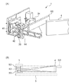
図8(A)は図2(A)のセンサユニット1の断面を示すと共に、センサユニット1と再帰反射部4の高さ位置関係(座標入力面5の法線方向)を説明するための説明図である。
FIG. 8A shows a cross section of the
受光部40(ラインCCD41、受光レンズ42、赤外フィルター44等で構成される)は、投光部30と面発光部50(コリメートレンズ54、拡散板60等で構成される)に挟まれた構成となっている。本願発明にあっては、再帰反射部4の上端部は、面発光部50の拡散板60の上端部と略同一の高さ位置にあり、再帰反射部4の下端は投光部30の下端と略同一の高さ位置にある。図8(B)は、その様子を示したものであり、センサユニット1と対向する辺に設けられた再帰反射部4の高さ関係を示している。尚、2辺に設けられた再帰反射部4の高さ位置は、両者とも同じ位置にあるが、センサユニット1側の再帰反射部4は、図8(B)には明示されていない。
The light receiving unit 40 (configured by the
図8(B)は、投光部30から対向する辺に設けられた再帰反射部4までの光線、及び、再帰反射部4から受光部40に到達する光線を示している。このいずれかの光線を遮れば、センサユニット1はその方向を検知できるので、指示具が座標入力面5に接触して無くても、言い換えれば近接入力が可能となる。
FIG. 8B shows light rays from the
また、図8(B)におけるセンサユニット1は、対向する辺に設けられたセンサユニット1の面発光部50’の光を受光する。その面発光部50’である所の拡散板60の上端部と再帰反射部4の上端部の高さを揃えているので、近接入力可能高さが再帰反射部4と拡散板60の繋ぎめで一定に保たれている。従って、操作者にとって操作性の良い座標入力装置を提供することが可能となる。
Further, the
<制御・演算ユニットの説明>
図1の制御・演算ユニット2とセンサユニット1a〜1dの間では、CCD用のCCD制御信号、CCD用のクロック信号、CCDの出力信号、及びLED駆動信号が送受信されている。
<Description of control / arithmetic unit>
A CCD control signal for CCD, a clock signal for CCD, an output signal of CCD, and an LED drive signal are transmitted and received between the control / arithmetic unit 2 and the
図4(A)は制御・演算ユニット2のブロック図である。CCD用の制御信号は、ワンチップマイコン等で構成される演算制御回路(CPU)71から出力されており、CCDのシャッタタイミングや、データの出力制御等を行っている。CCD用のクロック信号はクロック発生回路(CLK)72からセンサユニット1a〜1dに送信されると共に、ラインCCD41との同期をとって、各種制御を行うために、演算制御回路71にも入力されている。
FIG. 4A is a block diagram of the control / arithmetic unit 2. A control signal for the CCD is output from an arithmetic control circuit (CPU) 71 constituted by a one-chip microcomputer or the like, and performs CCD shutter timing, data output control, and the like. A clock signal for the CCD is transmitted from the clock generation circuit (CLK) 72 to the
LED駆動信号は演算制御回路71からLED駆動回路74a〜74dを経て、センサユニット1a〜1dの投光部30もしくは面発光部50の赤外LEDに供給されている。また、LED駆動回路74a〜74dは、後述するタイミングで、センサユニット1a〜1dのそれぞれの投光部30へもしくは面発光部50への電力供給を制御している。
The LED driving signal is supplied from the
センサユニット1a〜1dの受光部40であるラインCCD41からの検出信号(アナログ信号)は、各々制御・演算ユニット2のADコンバータ75a〜75dに入力され、演算制御回路71からの制御によって、デジタル信号に変換される。変換されたデジタル信号は必要に応じてメモリ73に記憶され、後述する方法で角度算出、さらには座標値が算出され、その結果を外部PC等の端末に通信インタフェース(例えば、USBインタフェース)76を介して出力する。
Detection signals (analog signals) from the
図4(B)は各種信号のタイミングチャートである。 FIG. 4B is a timing chart of various signals.
81、82がCCD用の制御信号であり、制御信号81の間隔で、ラインCCD41のシャッタ解放時間が決定される。82a、82b、82c及び82dはそれぞれセンサユニット1a、1b、1c及び1dへのゲート信号であり、ラインCCD41内部の光電変換部の電荷を読出部へ転送する信号である。83a、83b、83c及び83dは、それぞれのセンサユニット1a、1b、1c及び1dの投光部30の赤外LED31を駆動する信号である。また、84a、84b、84c及び84dは、それぞれのセンサユニット1a、1b、1c及び1dの面発光部50の赤外LED51〜53を駆動する信号である。
まず、制御信号81の最初の周期で一方の辺に設けられたセンサユニット1a及び1bの投光部30の赤外LED31を点灯すると共に、対向する辺に設けられたセンサユニット1c及び1dの面発光部50の赤外LED51〜53を点灯する。従って、センサユニット1aの受光部40は、投光部30が投光した光が対向する辺に設けられた再帰反射部4bで再帰反射した光と、対向する辺に設けられたセンサユニット1c及び1dの面発光部50の光を検出する。同様に、センサユニット1bの受光部40は、センサユニット1bの投光部30の再帰反射光と、センサユニット1c及び1dの面発光部50の光を検出する。そして、ゲート信号82a及び82bにより、センサユニット1a及び1bの受光部40の検出結果を出力する。
First, the
読み出される信号は、例えば、指等の指示具による入力がない場合、つまり、遮光部分がない場合には、それぞれのセンサユニット1a〜1dからの出力として、図3(E)のような光量分布が得られる。もちろん、このような光量分布がどのシステムでも必ず得られるわけではなく、再帰反射部4の特性や投光部30、面発光部50の特性、また、経時変化(反射面の汚れなど)によって、この光量分布は変化する。
For example, when there is no input by a pointing tool such as a finger, that is, when there is no light shielding portion, the read signal is output as the output from each of the
次に、次の制御信号81に基づき、今度は、センサユニット1c及び1dの投光部30(信号83c及び83d)とセンサユニット1a及び1bの面発光部50(信号84a及び84b)の赤外LEDが駆動される。そして、ゲート信号82c及び82dにより、センサユニット1c及び1dの受光部40の検出結果が出力される。
Next, based on the
センサユニット1a及び1bの投光部30は同時に発光するが、センサユニット1aの投光部30の光はセンサユニット1bの受光部40では検出されないように構成されている。その構成は、投光部30の投光範囲を制限する、あるいはセンサユニット1a及び1bの間に遮光板を設ける等の構成を用いれば良い。従って、図4(B)に示すとおり、少なくとも制御信号81の3周期分で必要とされる信号を検出することが可能である。さらには、センサユニット1c及び1dの読出期間中にセンサユニット1a及び1bを投光すれば、制御信号81の2周期分での信号取得も可能となる。
The
このように制御することで、高速な位置検出サンプリングレートを実現することが可能となる優れた効果が得られる。 By controlling in this way, it is possible to obtain an excellent effect that enables a high-speed position detection sampling rate to be realized.
図3(E)において、Aレベルが最大検出光量のレベルであり、Bレベルが最低検出光量レベルであるものとすれば、検出光のない状態では得られるレベルはBレベル付近になり、検出光量が増えるほどAレベルに近づく。このように、受光部40から出力されたアナログ信号は、逐次AD変換され演算制御回路71にデジタル信号として取り込まれる。
In FIG. 3E, if the A level is the maximum detected light amount level and the B level is the minimum detected light amount level, the level obtained in the absence of detected light is near the B level. As the value increases, it approaches A level. As described above, the analog signal output from the
図3(F)は、指等の指示具で入力を行う場合、つまり、検出光が遮られる場合の出力の例である。Cレベル部分が指示具で反射光が遮られるため、その部分のみ光量が低下している。 FIG. 3F illustrates an example of output when input is performed with an indicator such as a finger, that is, when detection light is blocked. Since the reflected light is blocked by the indicator at the C level portion, the amount of light is reduced only at that portion.
検出は、この光量分布の変化を検知して行う。具体的には、まず、図3(E)のような入力の無い初期状態(以後、初期状態で得られたデータを初期データ(あるいはリファレンスデータ)と言う)を予めメモリ73に記憶しておく。そして、それぞれのサンプル期間で得られる画素データとあらかじめ記憶しておいた初期データとの差分を算出することで、図3(F)のような変化があるかどうかを判定する。 The detection is performed by detecting the change in the light amount distribution. Specifically, first, an initial state without input (hereinafter, data obtained in the initial state is referred to as initial data (or reference data)) as shown in FIG. . Then, by calculating the difference between the pixel data obtained in each sample period and the initial data stored in advance, it is determined whether there is a change as shown in FIG.
具体的には、図3(F)に示すような閾値Vthaと出力信号を比較し、閾値Vtha以下となる画素番号を検出する。そして、出力レベルが閾値Vtha以下となる画素範囲を算出し、例えば、その中心を遮光物体が位置する方向と定義する。尚、ラインCCD41の画素番号Nは、図2(C)の光学系で明らかに解るように、光の到来方向(角度θ)を示す。従って、工場での組立時等において画素番号Nと角度θの関係を、予め関数として算出しておくことで、出力された画素番号Nを角度θに変換することが可能となる。
Specifically, a threshold value Vtha as shown in FIG. 3F is compared with the output signal, and a pixel number that is equal to or lower than the threshold value Vtha is detected. Then, a pixel range in which the output level is equal to or less than the threshold value Vtha is calculated, and for example, the center is defined as the direction in which the light shielding object is located. It should be noted that the pixel number N of the
<座標計算方法の説明>
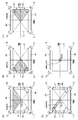
図5はセンサユニット1の視野範囲を説明するための図である。図5(A)はセンサユニット1aの視野範囲を説明するための図である。センサユニット1aの投光部30の光が対向する辺に設けられた再帰反射部4bで再帰反射され、センサユニット1aの受光部40で検出される。それと同時に、対向する辺に設けられたセンサユニット1b及び1cの面発光部50の光を検出する。従って、センサユニット1aの受光部40が検出する光の到来方向の範囲は、角度θaで表現される。従って、座標入力有効領域3内のハッチング部area−aの範囲に、指示具による入力指示が行われると、その方向の光が遮られ、センサユニット1aはその光の変化からその方向(角度)を検知することが可能となる。しかしながら、座標入力有効領域3内のハッチング部area−a外に入力指示動作が行われても、センサユニット1aはそれを検出することができない。
<Description of coordinate calculation method>
FIG. 5 is a diagram for explaining the visual field range of the
図5(B)はセンサユニット1bの視野範囲を説明するための図である。この場合、センサユニット1bの視野範囲は角度θbで表現される。従って、座標入力有効領域3内のハッチング部area−bの範囲に、指示具による入力指示が行われると、その方向の光が遮られ、センサユニット1bはその方向(角度)を検知することが可能となる。
FIG. 5B is a diagram for explaining the visual field range of the
図5(C)におけるハッチング部area−abは、センサユニット1a及び1bの受光部40の視野範囲の重複領域(図5(A)と図5(B)のハッチング部の重複領域)である。従って、このハッチング部area−abの領域内で、指示具による指示動作をすれば、センサユニット1a及び1bの夫々で、その方向を検知することが可能である。従って、センサユニット1aと1b間の距離と、各々のセンサユニット1a〜1dで得られた方向(角度)を用いて、幾何学的に指示位置を算出することが可能となる。
A hatched area area-ab in FIG. 5C is an overlapping region (overlapping region of the hatched portions in FIGS. 5A and 5B) of the visual field range of the
図1に示されるとおり、センサユニット1c及び1dはx軸を対称軸として、センサユニット1a及び1bと各々略対称な位置に配置されている。同様に、センサユニット1b及び1dはY軸を対称軸としてセンサユニット1a及び1cと各々略対称な位置に配置されている。従って、図6(A)の座標入力有効領域3のハッチング部area−cdの範囲内で指示された位置は、センサユニット1c及び1dで得られる角度情報により算出可能である。同様に、図6(B)で示されるハッチング部area−ac内は、センサユニット1a及び1cで得られる角度情報を用いてその指示位置を算出可能である。また、図6(C)で示されるハッチング部area−bd内は、センサユニット1b及び1dで得られる角度情報を用いてその指示位置を算出可能である。
As shown in FIG. 1, the
また、図6(D)のハッチング部area−acdの領域内は、センサユニット1c及び1dの検出結果を用いても、あるいはセンサユニット1a及び1cの検出結果を用いても、指示位置の算出が可能である。従って、両者の出力結果の平均値を用いて位置算出精度の向上が図られる。
In addition, in the hatched area area-acd area of FIG. 6D, the indicated position can be calculated using the detection results of the
さらには、ハッチング部area−ac(図6(B))からハッチング部area−cd(図6(A))へ連続的に座標入力が行われた場合、その途中で位置算出を行うためのセンサユニット1の組み合わせが変更される。その変更が起こると、例えば、センサユニットの位置のズレ等に要因、あるいは計測誤差等により、連続した座標入力動作を行ったにもかかわらず、検出される座標値が不連続となってしまう場合がある。言い換えれば、その組み合わせ変更により、座標算出分解能が低下する。
Furthermore, when coordinate input is continuously performed from the hatching area area-ac (FIG. 6B) to the hatching area area-cd (FIG. 6A), a sensor for calculating a position in the middle of the coordinate input is performed. The combination of
それを防止するために、図6(D)のα地点ではセンサユニット1a及び1cによる出力結果を採用し、β地点へ移動するに従って、センサユニット1c及び1dの出力結果を加味する。そして、β地点でセンサユニット1c及び1dの出力結果のみを採用する。このように、位置に応じてセンサユニット1a及び1cによる出力結果とセンサユニット1c及び1dの出力結果の重みを変える(加重平均)ことにより、忠実な指示位置の検出が可能となる優れた効果が得られる。
In order to prevent this, the output results of the
また、図6(E)に示されるハッチング部area−abcdはどのセンサユニット1の組み合わせでも位置算出が可能である。従って、原点Oを指示することによって、センサユニット1の各組み合わせで出力された出力結果が同一となるように、座標系を補正することが可能となる。
Moreover, the position of the hatched area area-abcd shown in FIG. 6E can be calculated by any combination of
以上述べたように、本願発明の座標入力装置にあっては、各センサユニット1a〜1dの視野範囲は、原点O、及び座標入力有効領域3に関して対向する辺側全域を有効視野範囲とする。そして、センサユニット1a〜1dの切替が発生する領域では、複数のセンサユニットa〜1dの組み合わせで位置検出ができるように視野範囲が設定されている。
As described above, in the coordinate input device of the present invention, the visual field range of each of the
<座標算出処理の説明>
図7は実施形態1の座標算出処理を示すフローチャートである。
<Description of coordinate calculation processing>
FIG. 7 is a flowchart showing the coordinate calculation process of the first embodiment.
まず、座標入力装置の電源が投入されると、ステップS102で、制御・演算ユニット2のポート設定、タイマ設定等の座標入力装置に係る各種初期化を行う。ステップS103で、ラインCCD41の画素有効範囲を、例えば、メモリ73に予め記憶されている設定値から設定する。また、ラインCCD41の初期読込動作の初期読込回数を設定する。
First, when the power of the coordinate input device is turned on, various initializations relating to the coordinate input device such as port setting and timer setting of the control / arithmetic unit 2 are performed in step S102. In step S103, the pixel effective range of the
尚、この初期読込動作は、座標入力装置の立ち上げ時のみに行うラインCCD41の不要電荷除去のための動作である。ラインCCD41では、動作させていないときに不要な電荷が蓄積している場合があり、その電荷が蓄積されている状態で座標入力動作を実行すると、検出不能になったり、誤検出の原因となる。そこで、これを避けるために、ステップS104では、投光部30及び面発光部50による投光を停止している状態で、所定回数の読込動作を実行する。これにより、不要電荷の除去を行う。
The initial reading operation is an operation for removing unnecessary charges of the
ステップS104で、ラインCCD41の読込動作を実行する。ステップS105で、所定回数以上の読込を実行したか否かを判定する。所定回数以上の読込を実行していない場合(ステップS105でNO)、ステップS104に戻る。一方、所定回数以上の読込を実行した場合(ステップS105でYES)、ステップS106に進む。
In step S104, the
ステップS106で、ベースデータとして、投光部30及び面発光部50の照明無しの状態のラインCCD41の画素データを取り込む。ステップS107で、ベースデータをメモリ73に記憶する。続いて、ステップS108で、リファレンスデータとして、投光部30及び面発光部50の照明有りの状態のラインCCD41の初期光量分布に相当する画素データを取り込む。ステップS109で、リファレンスデータをメモリ73に記憶する。
In step S106, the pixel data of the
尚、この照明有りの状態のリファレンスデータとは、センサユニット1自身の投光部30の照明と、センサユニット1の対向する辺に設けられた2個のセンサユニット1の面発光部50の照明である。また、座標入力有効領域3の上辺のセンサユニット1a及び1bの組と下辺のセンサユニット1c及び1dの組で異なるタイミングで照明してリファレンスデータを取り込む。これは、上辺のセンサユニット1a及び1bと下辺のセンサユニット1c及び1dが対向する配置であるため、同時に照明してしまうと、互いの照明を互いの受光部40にて検出してしまうことを避けるためである。
Note that the reference data in the presence of illumination includes illumination of the
そして、ステップS110で、全てのセンサユニット1a〜1dにおいてリファレンスデータの取込が終了したか否かを判定する。全てのセンサユニット1a〜1dにおいてリファレンスデータの取込が終了していない場合(ステップS110でNO)、ステップS108とステップS109を繰り返す。一方、全てのセンサユニット1a〜1dにおいてリファレンスデータの取込が終了した場合(ステップS110でYES)、ステップS111に進む。
In step S110, it is determined whether or not the reference data has been taken in all the
ここまでの処理が、電源投入時の初期設定動作になる。この初期設定動作は、座標入力装置に構成されているリセットスイッチ等により操作者の意図によって動作するように構成しても良いことは言うまでも無い。この初期設定動作を経て、指示具による通常の座標入力動作状態(通常取込動作状態)に移行することになる。 The processing so far is the initial setting operation when the power is turned on. It goes without saying that this initial setting operation may be configured to operate according to the operator's intention using a reset switch or the like configured in the coordinate input device. After this initial setting operation, a normal coordinate input operation state (normal capture operation state) by the pointing tool is entered.
ステップS111で、座標入力サンプリング状態で、ラインCCD41の通常取込動作を実行して、画素データ(光量分布)を取り込む。ステップS112で、全てのセンサユニット1a〜1dにおいて画素データの取込が終了したか否かを判定する。全てのセンサユニット1a〜1dの画素データの取込が終了していない場合(ステップS112でNO)、ステップS111を繰り返す。そして、全てのセンサユニット1a〜1dの画素データの取込が終了した場合(ステップS112でYES)、ステップ113で、初期化時に取得したリファレンスデータと画素データとを比較し、差分値を計算する。ステップS114で、遮光部分(入力)の有無を判定する。ステップS114で、入力がないと判定された場合(ステップS114でNO)、ステップS111に戻り、再度、画素データの取込を実行する。この時、この繰り返し周期を10[msec]程度に設定すれば、100回/秒のサンプリングになる。一方、入力があると判定された場合(ステップS114でYES)、ステップS115に進む。
In step S111, the normal capture operation of the
尚、図5及び図6で説明したとおり、座標入力有効領域3内の領域を分割して、その領域毎に遮光部分を検出するためのセンサユニット1a〜1dの組み合わせが決まっている。従って、入力動作が行われた場合、少なくとも2つのセンサユニットで遮光部分が検出されているはずであり、ステップS114で、遮光部分を検出したセンサユニットを特定する。仮に、入力が行われていない場合には、遮光部分を検出したセンサユニットはなく、再度、ステップS111に戻って、画素データの取込を繰り返す。
As described with reference to FIGS. 5 and 6, the combination of the
ステップS115で、遮光部分を検出したセンサユニットが2より大きい、つまり、図6(D)、もしくは図6(E)の重複領域を指示しているか、それ以外の領域を指示しているかを判定する。重複領域を指示している場合(ステップS115でYES)、Flag=1にセットする。一方、重複領域以外を指示している場合(ステップS115でNO)、Flag=0にセットする。 In step S115, it is determined whether the sensor unit that has detected the light-shielding portion is larger than 2, that is, whether the overlapping area in FIG. 6D or 6E is indicated or an area other than that is indicated. To do. If an overlapping area is designated (YES in step S115), Flag = 1 is set. On the other hand, when an area other than the overlapping area is instructed (NO in step S115), Flag = 0 is set.
ステップS118で、座標算出に必要な2つのセンサユニットの組み合わせを選択する。ステップS119で、選択された2つのセンサユニットで出力された角度情報と、そのセンサユニット間の距離情報を用いて指示位置(座標値)を算出する(第1の算出)。次に、ステップS120で、Flag=0であるか否かを判定する。Flag=0の場合(ステップS120でYES)、ここで算出された座標値を確定座標値として、ステップS123で、外部機器に出力する。その後、ステップS111に戻る。 In step S118, a combination of two sensor units necessary for coordinate calculation is selected. In step S119, the indicated position (coordinate value) is calculated using the angle information output by the two selected sensor units and the distance information between the sensor units (first calculation). Next, in Step S120, it is determined whether or not Flag = 0. If Flag = 0 (YES in step S120), the coordinate value calculated here is output as a determined coordinate value to an external device in step S123. Thereafter, the process returns to step S111.
一方、Flag=1の場合(ステップS120でNO)、指示位置算出可能な2つのセンサユニットの組み合わせは複数あり、ステップS121で全ての組み合わせで算出が完了したか否かを判定する。指示位置算出可能な残りのセンサユニットの組み合わせがある場合(ステップS121でNO)、ステップS118に戻り、再度指示位置算出を実行する。その結果、ステップS122で、複数の指示位置算出結果が存在することになるので、その平均値あるいは加重平均値等の座標値を算出する(第2の算出)。そして、算出された座標値値を確定座標として、ステップS123で、外部機器に出力する。 On the other hand, when Flag = 1 (NO in step S120), there are a plurality of combinations of two sensor units that can calculate the indicated position, and in step S121, it is determined whether or not the calculation has been completed for all the combinations. If there is a combination of remaining sensor units that can calculate the designated position (NO in step S121), the process returns to step S118, and the designated position is calculated again. As a result, in step S122, since there are a plurality of designated position calculation results, a coordinate value such as an average value or a weighted average value is calculated (second calculation). Then, in step S123, the calculated coordinate value value is output as a final coordinate to the external device.
以上説明したように、実施形態1によれば、センサユニットの受光部で安定した光出力信号が得られるので、検出される座標値の精度、分解能が向上する他、センサユニットの小型化が図られ、装置を小型化できる優れた効果が得られる。さらには、座標入力有効領域の対向する2辺のみに構成要素(センサユニット、再帰反射部)が配置できるので、マルチディスプレイに対応可能な大型、横長化した座標入力装置を提供することができる。 As described above, according to the first embodiment, a stable light output signal can be obtained at the light receiving unit of the sensor unit, so that the accuracy and resolution of detected coordinate values are improved and the sensor unit can be downsized. Thus, an excellent effect of downsizing the apparatus can be obtained. Furthermore, since the constituent elements (sensor unit, retroreflective portion) can be arranged only on the two opposing sides of the coordinate input effective area, a large and horizontally elongated coordinate input device that can support a multi-display can be provided.
<実施形態2>
本願発明の構成により、座標入力有効領域3の外側2辺に設けられた再帰反射部4a及び4bと、再帰反射部4a及び4bの両端近傍に各々設けたセンサユニット1a〜1dによる構成で、安定した光検出とそれによる操作性良好な座標入力装置が提供される。
<Embodiment 2>
According to the configuration of the present invention, the configuration includes the
このように構成することで、また、次のような新たな構成も可能となる。 With this configuration, the following new configuration is also possible.
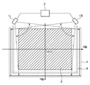
図9(A)は、本願発明をマルチディスプレイに適用した例である。表示領域βの範囲を座標入力有効領域とするために、センサユニット1a、1b、1c及び1d、及び再帰反射部4a及び4bが設けられている。図示が如くこの構成一式を左右隣に置けば(図中、構成要素を破線で示す)、表示面3面からなるマルチディスプレイをインタラクティブ化できる。ここでインタラクティブ化とは、表示面に表示されているオブジェクトを直接タッチすることで、表示制御をしたり、指示することによってその軌跡を表示したりすることが可能となる機能を言う。つまり、本願発明の実施形態1の構成を単位として、これを連結していくことで、いくらでも表示面を大きくしていくことが可能となる。表示画像の繋ぎ目には、再帰反射部等の遮蔽物が無いので、表示面をまたがって、連続的に座標入力が可能であり、操作性良好なインタラクティブディスプレイを提供できる優れた効果が得られる。
FIG. 9A shows an example in which the present invention is applied to a multi-display.
また、本願発明の構成要素は、図1に示される通り、2つのセンサバー8a及び8bに収納される。従って、図9(B)に示すように、既存のホワイトボードや壁等に、センサバー8a及び8bを2本装着することで、表示装置を直ぐにインタラクティブ化することが可能となる。この場合、構成部品が2点のみであり、ユーザが装着して『直ぐに』、『簡単に』、『何処でも』を可能とし、ユーザの利便性が大幅に向上する優れた効果が得られる。
Moreover, the component of this invention is accommodated in the two
以上説明したように、実施形態2によれば、実施形態1で説明した効果に加えて、座標入力装置の構成要素を座標入力面から取り外し可能な構成とすることで、容易に座標入力装置を可搬することが可能となる。 As described above, according to the second embodiment, in addition to the effects described in the first embodiment, the configuration of the coordinate input device can be easily removed from the coordinate input surface. It can be transported.
言い換えれば、従来スクリーンと一体に組み込まれた座標入力装置は表示スクリーンのサイズに応じて大きくなる。従って、製造段階、流通段階、販売段階において、その管理コスト、流通コストは大きく、またその設置にも大幅なコストを要する。スクリーンとして既存のホワイトボードや壁面、ショーウィンドウを利用しているディスプレイに、センサ部分を後から装着する製品形態とすることで、入力装置の小型化が図られ、コスト負担を大幅に軽減することが可能となる。また、ユーザにとっても持ち運び可能な構成とすることで、使用機会が増し、利便性向上に寄与することが可能となる優れた効果が得られる。 In other words, the conventional coordinate input device integrated with the screen becomes larger according to the size of the display screen. Therefore, in the manufacturing stage, distribution stage, and sales stage, the management cost and the distribution cost are large, and the installation cost is also large. By adopting a product form in which the sensor part is installed later on a display that uses an existing whiteboard, wall surface, or show window as a screen, the input device can be reduced in size and the cost burden can be greatly reduced. Is possible. Further, by adopting a configuration that can be carried by the user, it is possible to obtain an excellent effect of increasing use opportunities and contributing to improvement in convenience.
尚、本発明は、以下の処理を実行することによっても実現される。即ち、上述した実施形態の機能を実現するソフトウェア(プログラム)を、ネットワーク又は各種記憶媒体を介してシステム或いは装置に供給し、そのシステム或いは装置のコンピュータ(またはCPUやMPU等)がプログラムを読み出して実行する処理である。 The present invention can also be realized by executing the following processing. That is, software (program) that realizes the functions of the above-described embodiments is supplied to a system or apparatus via a network or various storage media, and a computer (or CPU, MPU, or the like) of the system or apparatus reads the program. It is a process to be executed.
Claims (11)
前記センサ手段は、
到来する光を受光する受光部と、
前記2辺の内、対向する辺に設けられた再帰反射部に対して光を投光する投光部と、
帯状の面から均一な拡散光を発光する面発光部とを備え、
前記センサ手段は、前記受光部によって、前記投光部で投光した光が前記対向する辺に設けられた前記再帰反射部によって再帰反射された光と、前記対向する辺に設けられた前記複数のセンサ手段の前記面発光部で発光した光を同時に検出する
ことを特徴とする座標入力装置。 A coordinate input device having a retroreflective portion provided on two opposite sides of a rectangular coordinate input effective area, and a plurality of sensor means provided on each of the two sides,
The sensor means includes
A light receiving unit for receiving incoming light;
A light projecting unit that projects light to a retroreflective unit provided on the opposite side of the two sides;
A surface light emitting unit that emits uniform diffused light from a band-shaped surface;
The sensor means includes the light reflected by the retroreflecting unit provided on the opposite side by the light projected by the light projecting unit by the light receiving unit, and the plurality of light provided on the opposing side. A coordinate input device that simultaneously detects light emitted from the surface light emitting unit of the sensor means.
ことを特徴とする請求項1に記載の座標入力装置。 Control means for simultaneously emitting light from at least one light projecting portion of the plurality of sensor means provided on one of the two sides and a surface light emitting portion of the plurality of sensor means provided on the side opposite to the one side. The coordinate input device according to claim 1, further comprising:
ことを特徴とする請求項1に記載の座標入力装置。 Control means for simultaneously emitting light from all the light projecting portions of the plurality of sensor means provided on one of the two sides and the surface light emitting portions of the plurality of sensor means provided on the side opposite to the one side. The coordinate input device according to claim 1, further comprising:
ことを特徴とする請求項1乃至3のいずれか1項に記載の座標入力装置。 The coordinate input device according to any one of claims 1 to 3, wherein the light receiving unit is disposed between the light projecting unit and the surface light emitting unit of each of the plurality of sensor units.
前記座標入力有効領域における前記2辺の内の一辺に設けられた前記複数のセンサ手段の内の1つの第1のセンサ手段の前記面発光部の発光面の法線方向に、該一辺に対向する辺に設けられた前記複数のセンサ手段の内の1つの第2のセンサ手段が設けられている
ことを特徴とする請求項1乃至4のいずれか1項に記載の座標入力装置。 Each of the plurality of sensor means is provided in the vicinity of a corner of the coordinate input effective area,
Opposite to the one side in the normal direction of the light emitting surface of the surface light emitting portion of one of the plurality of sensor means provided on one side of the two sides in the coordinate input effective area. The coordinate input device according to any one of claims 1 to 4, wherein one second sensor means among the plurality of sensor means provided on a side to be provided is provided.
ことを特徴とする請求項5に記載の座標入力装置。 The normal direction of the light emitting surface of the surface light emitting portion of the first sensor means coincides with the optical axis direction of the light projecting portion of the second sensor means. Coordinate input device.
ことを特徴とする請求項1乃至6のいずれか1項に記載の座標入力装置。 The height from the coordinate input effective region to the upper end of the retroreflective portion in the normal direction of the coordinate input effective region is equal to the height from the upper end of the surface light emitting unit of each of the plurality of sensor means. The coordinate input device according to any one of claims 1 to 6, wherein the coordinate input device is provided.
前記複数のセンサ手段における前記2辺の内の一辺に設けられた前記複数のセンサ手段の内の1つの第1のセンサ手段の前記受光部の視野範囲と、該一辺に対向する辺に設けられた前記複数のセンサ手段の内の第2のセンサ手段であって、前記第1のセンサ手段の対角方向に設けられている前記第2のセンサ手段の視野範囲とが重複している
ことを特徴とする請求項1乃至7のいずれか1項に記載の座標入力装置。 Each of the plurality of sensor means is provided in the vicinity of a corner of the coordinate input effective area,
Of the plurality of sensor means, provided in one of the plurality of sensor means, the field of view of the light receiving portion of one of the plurality of sensor means, and the side opposite to the one side. The second sensor means of the plurality of sensor means, wherein the visual field range of the second sensor means provided in the diagonal direction of the first sensor means overlaps. The coordinate input device according to any one of claims 1 to 7, wherein the coordinate input device is characterized in that:
前記判定手段の判定の結果、前記2つのセンサ手段の受光部のみで前記影が検出されている場合、該2つのセンサ手段の受光部による影の検出結果に基づいて、入力された座標値を算出する第1の算出手段と、
前記判定手段の判定の結果、前記2つより大きい数のセンサ手段の受光部で前記影を検出している場合、前記2つより大きい数のセンサ手段から選択され得る2つのセンサ手段の組み合わせそれぞれについて、前記2つのセンサ手段の受光部による影の検出結果に基づいて、入力された座標値を算出し、各組み合わせについて算出された座標値の平均値の座標値を算出する第2の算出手段と、
前記第1の算出手段あるいは前記第2の算出手段で算出された座標値を出力する出力手段と
を更に備えることを請求項1乃至8のいずれか1項に記載の座標入力装置。 Regarding the shadow generated by the coordinate input operation, the shadow is detected by only the light receiving portions of the two sensor means among the plurality of sensor means, or the shadow is detected by the light receiving portions of the sensor means having a number greater than two. Determining means for determining whether or not is detected;
As a result of the determination by the determination means, when the shadow is detected only by the light receiving portions of the two sensor means, the input coordinate value is calculated based on the shadow detection results by the light receiving portions of the two sensor means. First calculating means for calculating;
As a result of the determination by the determination means, when the shadow is detected by the light receiving portions of the sensor means greater than the two, each combination of two sensor means that can be selected from the sensor means greater than the two Second calculation means for calculating an input coordinate value based on a shadow detection result by the light receiving unit of the two sensor means and calculating an average coordinate value of the coordinate values calculated for each combination. When,
The coordinate input device according to claim 1, further comprising: an output unit that outputs a coordinate value calculated by the first calculation unit or the second calculation unit.
判定手段が、座標入力動作に対し、前記複数のセンサ手段の内、2つのセンサ手段の受光部によって光を検出しているか、あるいは2より大きい数のセンサ手段の受光部によって光を検出しているかを判定する判定工程と、
第1の算出手段が、前記判定工程の判定の結果、前記2つのセンサ手段の受光部によって光を検出している場合、該2つのセンサ手段の受光部による光の検出結果に基づいて、入力された座標値を算出する第1の算出工程と、
第2の算出手段が、前記判定工程の判定の結果、前記2つより大きい数のセンサ手段の受光部によって光を検出している場合、前記2つより大きい数のセンサ手段から選択され得る2つのセンサ手段の組み合わせそれぞれについて、前記2つのセンサ手段の受光部による光の検出結果に基づいて、入力された座標値を算出し、各組み合わせについて算出された座標値の平均値の座標値を算出する第2の算出工程と、
出力手段が、前記第1の算出工程あるいは前記第2の算出工程で算出された座標値を出力する出力工程と
を備えることを特徴とする座標入力装置の制御方法。 A control method for a coordinate input device according to claim 1,
In response to the coordinate input operation, the determination unit detects light by the light receiving units of the two sensor units among the plurality of sensor units, or detects light by the light receiving units of the sensor units greater than two. A determination step for determining whether or not
When the first calculation means detects light by the light receiving portions of the two sensor means as a result of the determination in the determination step, the input is based on the light detection results by the light receiving portions of the two sensor means. A first calculation step of calculating the coordinate values obtained;
When the second calculation means detects light by the light receiving units of the sensor means greater than the two as a result of the determination in the determination step, the second calculation means may be selected from the sensor means greater than the two. For each combination of two sensor means, an input coordinate value is calculated based on a light detection result by the light receiving unit of the two sensor means, and an average coordinate value of the coordinate values calculated for each combination is calculated. A second calculating step,
An output means comprises: an output step of outputting the coordinate value calculated in the first calculation step or the second calculation step.
前記コンピュータを、
座標入力動作に対し、前記複数のセンサ手段の内、2つのセンサ手段の受光部によって光を検出しているか、あるいは2より大きい数のセンサ手段の受光部によって光を検出しているかを判定する判定手段と、
前記判定手段の判定の結果、前記2つのセンサ手段の受光部によって光を検出している場合、該2つのセンサ手段の受光部による光の検出結果に基づいて、入力された座標値を算出する第1の算出手段と、
前記判定手段の判定の結果、前記2つより大きい数のセンサ手段の受光部によって光を検出している場合、前記2つより大きい数のセンサ手段から選択され得る2つのセンサ手段の組み合わせそれぞれについて、前記2つのセンサ手段の受光部による光の検出結果に基づいて、入力された座標値を算出し、各組み合わせについて算出された座標値の平均値の座標値を算出する第2の算出手段と、
前記第1の算出手段あるいは前記第2の算出手段で算出された座標値を出力する出力手段と
して機能させることを特徴とするプログラム。 A program for causing a computer to control the coordinate input device according to claim 1,
The computer,
For coordinate input operation, it is determined whether light is detected by light receiving parts of two sensor means among the plurality of sensor means or light is detected by light receiving parts of a number of sensor means larger than two. A determination means;
As a result of the determination by the determination means, when light is detected by the light receiving portions of the two sensor means, the input coordinate value is calculated based on the light detection results by the light receiving portions of the two sensor means. First calculating means;
As a result of the determination by the determination means, when light is detected by the light receiving portions of the sensor means greater than the two, each combination of two sensor means that can be selected from the sensor means greater than the two Second calculation means for calculating an input coordinate value based on a light detection result by the light receiving unit of the two sensor means, and calculating an average coordinate value of the coordinate values calculated for each combination; ,
A program that functions as an output unit that outputs a coordinate value calculated by the first calculation unit or the second calculation unit.
Priority Applications (2)
| Application Number | Priority Date | Filing Date | Title |
|---|---|---|---|
| JP2010247838A JP5591069B2 (en) | 2010-11-04 | 2010-11-04 | Coordinate input device, control method therefor, and program |
| US13/284,079 US8791925B2 (en) | 2010-11-04 | 2011-10-28 | Coordinate input apparatus, control method therefor and program |
Applications Claiming Priority (1)
| Application Number | Priority Date | Filing Date | Title |
|---|---|---|---|
| JP2010247838A JP5591069B2 (en) | 2010-11-04 | 2010-11-04 | Coordinate input device, control method therefor, and program |
Publications (2)
| Publication Number | Publication Date |
|---|---|
| JP2012099024A JP2012099024A (en) | 2012-05-24 |
| JP5591069B2 true JP5591069B2 (en) | 2014-09-17 |
Family
ID=46019168
Family Applications (1)
| Application Number | Title | Priority Date | Filing Date |
|---|---|---|---|
| JP2010247838A Expired - Fee Related JP5591069B2 (en) | 2010-11-04 | 2010-11-04 | Coordinate input device, control method therefor, and program |
Country Status (2)
| Country | Link |
|---|---|
| US (1) | US8791925B2 (en) |
| JP (1) | JP5591069B2 (en) |
Families Citing this family (10)
| Publication number | Priority date | Publication date | Assignee | Title |
|---|---|---|---|---|
| JP6031293B2 (en) | 2012-08-03 | 2016-11-24 | キヤノン株式会社 | Coordinate input device, control method therefor, and program |
| JP6021531B2 (en) * | 2012-08-31 | 2016-11-09 | キヤノン株式会社 | Coordinate input device, control method therefor, and program |
| JP5950767B2 (en) * | 2012-08-31 | 2016-07-13 | キヤノン株式会社 | Coordinate input device, control method therefor, and program |
| TW201426463A (en) * | 2012-12-26 | 2014-07-01 | Pixart Imaging Inc | Optical touch system |
| CN103914185A (en) * | 2013-01-07 | 2014-07-09 | 原相科技股份有限公司 | Optical touch system |
| TWI496059B (en) * | 2013-11-27 | 2015-08-11 | Wistron Corp | Touch locating method and optical touch system |
| TWI498794B (en) * | 2013-11-28 | 2015-09-01 | Wistron Corp | Sensing method of optical touch |
| JP6218590B2 (en) * | 2013-12-18 | 2017-10-25 | キヤノン株式会社 | Coordinate input device and control method thereof |
| US10310668B2 (en) * | 2016-01-18 | 2019-06-04 | Coretronic Corporation | Touch screen display system and a method for controlling a touch screen display system |
| TWI705366B (en) * | 2019-01-28 | 2020-09-21 | 緯創資通股份有限公司 | Optical touch device and optical touch method |
Family Cites Families (10)
| Publication number | Priority date | Publication date | Assignee | Title |
|---|---|---|---|---|
| US4507557A (en) | 1983-04-01 | 1985-03-26 | Siemens Corporate Research & Support, Inc. | Non-contact X,Y digitizer using two dynamic ram imagers |
| JPH11110116A (en) * | 1997-08-07 | 1999-04-23 | Fujitsu Ltd | Optical position detector |
| JP3836998B2 (en) | 1999-08-02 | 2006-10-25 | 株式会社リコー | Coordinate detection device |
| JP4094794B2 (en) * | 1999-09-10 | 2008-06-04 | 株式会社リコー | Coordinate detection apparatus, information storage medium, and coordinate detection method |
| JP2001282445A (en) * | 2000-03-31 | 2001-10-12 | Ricoh Co Ltd | Coordinate input / detection device and information display input device |
| JP2003280802A (en) | 2002-03-22 | 2003-10-02 | Canon Inc | Coordinate input device |
| JP4118664B2 (en) | 2002-12-06 | 2008-07-16 | リコーエレメックス株式会社 | Coordinate detection device |
| JP2004272353A (en) | 2003-03-05 | 2004-09-30 | Canon Inc | Coordinate input device |
| JP4429047B2 (en) * | 2004-03-11 | 2010-03-10 | キヤノン株式会社 | Coordinate input device, control method therefor, and program |
| JP5451538B2 (en) * | 2010-06-15 | 2014-03-26 | キヤノン株式会社 | Coordinate input device |
-
2010
- 2010-11-04 JP JP2010247838A patent/JP5591069B2/en not_active Expired - Fee Related
-
2011
- 2011-10-28 US US13/284,079 patent/US8791925B2/en not_active Expired - Fee Related
Also Published As
| Publication number | Publication date |
|---|---|
| US20120113057A1 (en) | 2012-05-10 |
| US8791925B2 (en) | 2014-07-29 |
| JP2012099024A (en) | 2012-05-24 |
Similar Documents
| Publication | Publication Date | Title |
|---|---|---|
| JP5591069B2 (en) | Coordinate input device, control method therefor, and program | |
| JP4442877B2 (en) | Coordinate input device and control method thereof | |
| JP5489886B2 (en) | Coordinate input device, light receiving device in the device, and manufacturing method thereof | |
| JP5875445B2 (en) | Coordinate input device | |
| JP6021531B2 (en) | Coordinate input device, control method therefor, and program | |
| JP6031293B2 (en) | Coordinate input device, control method therefor, and program | |
| JP6218590B2 (en) | Coordinate input device and control method thereof | |
| JP2012048403A (en) | Coordinate input device and control method thereof, and program | |
| JP6334980B2 (en) | Coordinate input device, control method therefor, and program | |
| JP5814608B2 (en) | Coordinate input device, control method therefor, and program | |
| JP2006059153A (en) | Optical coordinate input device | |
| JP2005173684A (en) | Optical coordinate input device | |
| JP2004185283A (en) | Optical coordinate input device | |
| JP5865053B2 (en) | Coordinate input device, control method of coordinate input device, and program | |
| CN103064560A (en) | Multipoint touch screen | |
| JP5950767B2 (en) | Coordinate input device, control method therefor, and program | |
| JP2007072587A (en) | Coordinate-input device, control method of coordinate-input device, control program, and storage medium | |
| JP2009116822A (en) | Coordinate input device, control method therefor, and program | |
| JP2006350908A (en) | Optical information input device | |
| JP5629595B2 (en) | Coordinate input device | |
| JP5969794B2 (en) | Coordinate input device | |
| JP2005352756A (en) | Shading type coordinate input device and coordinate input method | |
| JP2005071022A (en) | Coordinate input device, coordinate input method | |
| JP5738112B2 (en) | Coordinate input device, control method therefor, and program | |
| JP2006065654A (en) | Coordinate input device, control method of coordinate input device, control program, and storage medium |
Legal Events
| Date | Code | Title | Description |
|---|---|---|---|
| A621 | Written request for application examination |
Free format text: JAPANESE INTERMEDIATE CODE: A621 Effective date: 20131030 |
|
| A977 | Report on retrieval |
Free format text: JAPANESE INTERMEDIATE CODE: A971007 Effective date: 20140619 |
|
| TRDD | Decision of grant or rejection written | ||
| A01 | Written decision to grant a patent or to grant a registration (utility model) |
Free format text: JAPANESE INTERMEDIATE CODE: A01 Effective date: 20140630 |
|
| A61 | First payment of annual fees (during grant procedure) |
Free format text: JAPANESE INTERMEDIATE CODE: A61 Effective date: 20140729 |
|
| LAPS | Cancellation because of no payment of annual fees |