JP6218590B2 - Coordinate input device and control method thereof - Google Patents
Coordinate input device and control method thereof Download PDFInfo
- Publication number
- JP6218590B2 JP6218590B2 JP2013261840A JP2013261840A JP6218590B2 JP 6218590 B2 JP6218590 B2 JP 6218590B2 JP 2013261840 A JP2013261840 A JP 2013261840A JP 2013261840 A JP2013261840 A JP 2013261840A JP 6218590 B2 JP6218590 B2 JP 6218590B2
- Authority
- JP
- Japan
- Prior art keywords
- coordinate
- sensor unit
- unit
- sensor
- light receiving
- Prior art date
- Legal status (The legal status is an assumption and is not a legal conclusion. Google has not performed a legal analysis and makes no representation as to the accuracy of the status listed.)
- Active
Links
Images


Classifications
-
- G—PHYSICS
- G06—COMPUTING; CALCULATING OR COUNTING
- G06F—ELECTRIC DIGITAL DATA PROCESSING
- G06F3/00—Input arrangements for transferring data to be processed into a form capable of being handled by the computer; Output arrangements for transferring data from processing unit to output unit, e.g. interface arrangements
- G06F3/01—Input arrangements or combined input and output arrangements for interaction between user and computer
- G06F3/03—Arrangements for converting the position or the displacement of a member into a coded form
- G06F3/041—Digitisers, e.g. for touch screens or touch pads, characterised by the transducing means
- G06F3/042—Digitisers, e.g. for touch screens or touch pads, characterised by the transducing means by opto-electronic means
- G06F3/0428—Digitisers, e.g. for touch screens or touch pads, characterised by the transducing means by opto-electronic means by sensing at the edges of the touch surface the interruption of optical paths, e.g. an illumination plane, parallel to the touch surface which may be virtual
Description
本発明は、情報の入力や選択をするために指等の指示具によって座標入力面に入力された座標位置を光学的に検出する座標入力装置に関するものである。特に、着脱可能で、可搬性を有する座標入力装置に関するものである。 The present invention relates to a coordinate input device that optically detects a coordinate position input to a coordinate input surface by an indicator such as a finger in order to input or select information. In particular, the present invention relates to a coordinate input device that is detachable and has portability.
従来、この種の座標入力装置として、各種方式の座標入力装置(タッチパネルやデジタイザ)が提案、または製品化されている。例えば、特殊な器具等を用いずに、指で画面上をタッチすることで、PC(パーソナルコンピュータ)等の端末の操作を簡単に行うことがきるタッチパネル等が広く用いられている。 Conventionally, various types of coordinate input devices (touch panels and digitizers) have been proposed or commercialized as this type of coordinate input device. For example, a touch panel that can easily operate a terminal such as a PC (personal computer) by touching the screen with a finger without using a special instrument is widely used.
座標入力方式としては、抵抗膜を用いたもの、または、超音波を用いたもの等、種々のものがある。光を用いたものとして、座標入力面外側に再帰性反射材を設け、投光部からの光を再帰反射材で反射し、その光量分布を受光部により検出する方式(光学遮光方式)が知られている(例えば、特許文献1参照)。この方式は、座標入力領域内の指等で遮光された遮光部分(領域)の方向を検出し、遮光位置、つまり、座標入力位置の座標を決定する。 As a coordinate input method, there are various methods such as a method using a resistance film or a method using ultrasonic waves. As a method using light, a retroreflective material is provided outside the coordinate input surface, the light from the light projecting part is reflected by the retroreflective material, and the light quantity distribution is detected by the light receiving part (optical shading method). (For example, refer to Patent Document 1). In this method, the direction of a light-shielding portion (area) shielded by a finger or the like in the coordinate input area is detected, and the light-shielding position, that is, the coordinates of the coordinate input position are determined.
特許文献1の構成を一般化した例として、図14の構成を示す。図14は、座標入力面の両端に配置されたセンサユニット2L及び2Rと、座標を入力する際に使用する座標入力面である所の座標入力有効領域5が示される。そして、座標入力有効領域5の周囲3辺には、進入してきた光を進入してきた方向に再帰的に反射する再帰反射部4が設けられている。
As an example of generalizing the configuration of
センサユニット2L及び2Rは、投光部及び受光部(不図示)を有している。投光部は、座標入力有効領域5の入力面にほぼ平行に扇形に広がる光を投光し、受光部は、その光が再帰反射部4で再帰反射され、戻ってきた光を受光する。座標入力装置は、2つのセンサユニット2L及び2Rでそれぞれ検知された光の遮光方向(遮光角度θL及びθR)と当該センサユニット間の距離に基づいて、座標入力有効領域5に入力された指示位置Pを算出することができる。
The
尚、図中3はセンサユニット2L及び2Rを制御し、また、取得したセンサユニット2L及び2Rの出力信号を処理、あるいはその処理結果を外部装置に出力する演算制御回路である。
In the figure,
また、特許文献2では、多数のセンサユニットを使って、大画面の座標入力装置を小型なシステムで実現するための発明が開示されている。さらに、特許文献3では、デバイスを任意の位置に設置できるようにして使い勝手を向上するシステムが開示されている。
この種の座標入力装置を表示装置と一体にすることによって、表示装置の表示画面をタッチすることで、表示状態を制御したり、あたかも紙と鉛筆の様な関係で、指示位置の軌跡を筆跡として表示したりすることが可能となる。 By integrating this type of coordinate input device with the display device, the display state can be controlled by touching the display screen of the display device, or the locus of the indicated position can be drawn by hand as if it were a pencil and paper. Can be displayed.
表示装置としては、液晶表示装置等の各種方式のフラットパネルディスプレイやフロントプロジェクターが知られている。フラットパネルディスプレイの場合には、座標入力装置を重ねて配置すれば、このような操作環境を実現でき、スマートフォン等の携帯機器はその代表例と言える。フラットパネルディスプレイの大型化に伴い、大型のタッチパネルと組み合わせて、例えば、デジタルサイネージと言った分野でもその導入が進んでいる。 As display devices, flat panel displays and front projectors of various types such as liquid crystal display devices are known. In the case of a flat panel display, such an operation environment can be realized by arranging coordinate input devices in a stacked manner, and a portable device such as a smartphone can be said to be a representative example. With the increase in size of flat panel displays, in combination with large touch panels, for example, digital signage has been introduced.
このような装置では、構成上いくつかの誤差が発生する。主なものを挙げると、まず、光を検出する受光部には、CCDラインセンサやCMOSセンサ等の受光デバイスが使用される。受光デバイスにおける受光は画素単位で行われるから、このときに量子化誤差が発生する。次に、受光デバイスが検出した画素の番号を角度値へ変換するときには、テーブル参照あるいは多項式近似による変換等の方法を用いるが、いずれの方法でも多少の誤差を発生する。さらに、装置が筐体に固定的に取り付けられる場合などには、座標算出に使用される基準角度を記録するなどの処理が行われる。これは、例えば、装置の組み立て時に、水平方向などの基準となる角度を示す画素の番号を測定して、装置内のメモリに記録する。このときに、測定の誤差などが発生する。さらに、経年変化などで装置の取り付け位置がずれるなどすると、さらに誤差が発生することも考えられる。これらのさまざまな誤差要因によって、センサが検出する角度は誤差を持つことになる。 In such an apparatus, some errors occur in the configuration. First, a light receiving device such as a CCD line sensor or a CMOS sensor is used for a light receiving unit that detects light. Since light reception by the light receiving device is performed in units of pixels, a quantization error occurs at this time. Next, when converting the pixel number detected by the light receiving device into an angle value, a method such as table lookup or conversion by polynomial approximation is used, but either method generates some error. Further, when the apparatus is fixedly attached to the housing, processing such as recording a reference angle used for coordinate calculation is performed. For example, at the time of assembling the apparatus, the number of a pixel indicating a reference angle such as a horizontal direction is measured and recorded in a memory in the apparatus. At this time, a measurement error or the like occurs. Furthermore, if the mounting position of the device is shifted due to secular change or the like, further errors may occur. Due to these various error factors, the angle detected by the sensor has an error.
センサユニットの検出角度が誤差を持つと、タッチされた位置に対して、算出した画面上の座標が合わないという問題が発生する。両者の差を小さくするには、受光デバイスの画素分解能や、装置の機械的精度を高くするなどして、発生する誤差を小さくする必要がある。実際には、コストや機能/性能のバランスなどを考慮した上で設計レベルが決められる。 If the detection angle of the sensor unit has an error, there is a problem that the calculated coordinates on the screen do not match the touched position. In order to reduce the difference between the two, it is necessary to reduce the generated error by increasing the pixel resolution of the light receiving device and the mechanical accuracy of the apparatus. Actually, the design level is determined in consideration of the cost and the balance of function / performance.
また、特許文献2は、センサユニットの組み合わせを変えて、画面を複数の領域に分割して指示位置を算出するシステムとなっている。このようなシステムにおいて、センサユニットが検出する角度に誤差が発生すると、タッチされた位置と算出した画面上の座標が合わないという問題のほかに、複数に分割された領域の境界部において座標値が一致しないという、別の問題が発生する。この問題は、複数に分割された領域毎に、誤差の出かた(誤差の方向及び距離)が異なるために発生する。その結果、例えば、画面内で描画をしたときに、特定の位置で座標が不連続となるなどして、とても目立ちやすい。
この問題の改善策として、境界部付近で、境界を挟む2つの領域で算出した座標値を補間するという方法がある。この方法では、境界部をある程度なめらかに接続することができて、不連続性は目立たなくなる。しかしながら、この方法は、2つの座標値の差を小さくするわけではなく、2つの座標値の差を境界部付近の小さな領域で接続しなければならないため、どうしても不自然さが残りやすい。 As a remedy for this problem, there is a method of interpolating the coordinate values calculated in two regions sandwiching the boundary near the boundary. In this method, the boundary portions can be smoothly connected to some extent, and the discontinuity becomes inconspicuous. However, this method does not reduce the difference between the two coordinate values, and the difference between the two coordinate values must be connected in a small area near the boundary portion, so unnaturalness tends to remain.
本発明は上記の課題を解決するためになされたものであり、座標入力有効領域を複数の領域に分割して指示位置の座標を算出する場合に、領域の境界における座標の不連続性を改善する座標入力装置及びその制御方法、プログラムを提供することを目的とする。 The present invention has been made to solve the above-described problem, and improves the discontinuity of coordinates at the boundary between regions when the coordinate input effective region is divided into a plurality of regions and the coordinates of the indicated position are calculated. An object of the present invention is to provide a coordinate input device, a control method therefor, and a program.
上記の目的を達成するための本発明による座標入力装置は以下の構成を備える。即ち、
到来光を受光する受光部をそれぞれが備える、少なくとも4つのセンサユニットを用いて、座標入力有効領域に対する指示位置を検出する座標入力装置であって、
前記少なくとも4つのセンサユニットの1つのセンサユニットの受光部において、他のセンサユニットが位置する方向を示す角度情報を検出する検出手段と、
前記検出手段が検出した角度情報に基づいて、共通の座標計測点に対する座標値を、前記少なくとも4つのセンサユニットから少なくとも2つ選択するための複数通りの組み合わせそれぞれによって算出する座標計測点算出手段と、
前記座標計測点算出手段が算出した前記共通の座標計測点に対する複数の座標値についての補正値と、前記受光部の受光状態とに基づいて、前記指示位置の座標値を算出する座標算出手段と、
を備える。
In order to achieve the above object, a coordinate input device according to the present invention comprises the following arrangement. That is,
A coordinate input device that detects an indication position with respect to a coordinate input effective area using at least four sensor units each including a light receiving unit that receives incoming light,
Detecting means for detecting angle information indicating a direction in which another sensor unit is located in a light receiving portion of one sensor unit of the at least four sensor units;
Coordinate measurement point calculation means for calculating coordinate values for a common coordinate measurement point by each of a plurality of combinations for selecting at least two of the at least four sensor units based on the angle information detected by the detection means; ,
A correction value for a plurality of coordinate values for said common coordinate measurement points the coordinate measuring point calculation means has calculated, based on the light receiving state of the light receiving portion, and a coordinate calculation means for calculating the coordinate value of the indicated position ,
Is provided.
本発明によれば、座標入力有効領域を複数の領域に分割して指示位置の座標を算出する場合に、領域の境界における座標の不連続性を改善する座標入力装置及びその制御方法、プログラムを提供できる。 According to the present invention, when the coordinate input effective area is divided into a plurality of areas and the coordinates of the designated position are calculated, the coordinate input device that improves the discontinuity of coordinates at the boundary of the area, the control method thereof, and the program Can be provided.
以下、添付の図面を参照して、本発明をその好適な実施形態に基づいて詳細に説明する。尚、以下の実施形態において示す構成は一例に過ぎず、本発明は図示された構成に限定されるものではない。 Hereinafter, the present invention will be described in detail based on preferred embodiments with reference to the accompanying drawings. The configurations shown in the following embodiments are merely examples, and the present invention is not limited to the illustrated configurations.
<実施形態1>
実施形態1の座標入力装置の概略構成を、図1を用いて説明する。
<
A schematic configuration of the coordinate input apparatus according to the first embodiment will be described with reference to FIG.
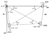
図中、1Lは少なくとも2個の角度検出センサ部であるところのセンサユニット2−L1及び2−L2(第1のセンサユニット及び第2のセンサユニット)を装備する筺体であるところのセンサバーである。また、1Rは、2−R1及び2−R2(第3のセンサユニット及び第4のセンサユニット)を装備する筺体であるところのセンサバーである。 In the figure, 1L is a sensor bar which is a housing equipped with sensor units 2-L1 and 2-L2 (first sensor unit and second sensor unit) which are at least two angle detection sensor units. . Moreover, 1R is a sensor bar which is a housing equipped with 2-R1 and 2-R2 (a third sensor unit and a fourth sensor unit).
各々のセンサバー1L及び1R(総称する場合は、センサバー1と表記)は、図示のように矩形状の座標入力有効領域5の対向する2辺の外側に設けられる。センサバー1L及び1Rは平行で、同一の長さとなっている。
Each
表示装置が仮にフロントプロジェクターとすれば、表示領域は座標入力有効領域5の範囲内に設定され、例えば、平面状のホワイトボード6に投影される。無論、ホワイトボード6に限定されるものではなく、壁面等であっても良い。
If the display device is a front projector, the display area is set within the range of the coordinate input
センサバー1L及び1Rの側面にはそれぞれ、図示のように再帰反射部4L及び4R(総称する場合は、再帰反射部4と表記)が装着されている。そして、再帰反射部4L及び4Rはそれぞれ、対向する辺に設けられたセンサバー1Lあるいは1Rのセンサユニットが投光した赤外光を再帰的に反射できるように構成してある。
センサバー1Lにはセンサユニット2−L1及び2−L2が内蔵され、センサバー1Rにはセンサユニット2−R1及び2−R2が内蔵されている。センサバー1Lに内蔵される演算制御回路3Lはセンサユニット2−L1及び2−L2を制御して、その出力結果を演算処理すると共に、センサバー1Rの演算制御回路3Rを制御する。センサバー1Rの演算制御回路3Rは、センサユニット2−R1及び2−R2を制御して、その出力結果を演算処理して、センサバー1Lの演算制御回路3Lにその結果を送信する。そして、センサバー1Lの演算制御回路3Lは、4つのセンサユニット2−L1、2−L2、2−R1及び2−R2からの出力結果を処理して、指示位置(タッチ位置)を算出し、パーソナルコンピュータ等の外部機器へ結果を出力する。
The
図1では、センサバー1Lの演算制御回路3Lとセンサバー1Rの演算制御回路3Rとはコードで接続される構成(つまり、有線接続)となっているが、これに限定されない。例えば、無線等の通信機能を互いに搭載して、それらの通信機能を使用してデータの送受信(無線接続)を行っても良い。
In FIG. 1, the
尚、以後の説明にあっては、水平方向をX軸(図面右側が+)、天地方向をY軸(下側が+)として説明する。 In the following description, the horizontal direction will be described as the X axis (+ on the right side of the drawing), and the vertical direction will be described as the Y axis (lower side is +).
図2はセンサユニット2−L1、2−L2、2−R1及び2−R2(総称する場合は、センサユニット2と表記する)の詳細構成を示す図である。図2(A)は図1における断面A−Aであり、図2(B)及び(C)は図中の矢印方向から見た正面図である。 FIG. 2 is a diagram showing a detailed configuration of the sensor units 2-L1, 2-L2, 2-R1, and 2-R2 (generically referred to as the sensor unit 2). 2A is a cross section AA in FIG. 1, and FIGS. 2B and 2C are front views as seen from the direction of the arrows in the figure.
図2(A)において、センサユニット2は、センサバー1に収納されており、座標入力有効領域5に向けて光を投稿する投光部30及び到来光を受光する受光部40で構成される。投光部30と受光部40の距離はL_pdであり、その間に再帰反射部4が図示のように設けられている。45は光透過性の部材であって、センサバー1内へのゴミ等の異物の侵入を防止するための保護部材である。
2A, the
図2(B)において、投光部30は、発光部である赤外LED31、投光レンズ32、両者を固定するための接着層33で構成される。投光レンズ32は、赤外LED31の光を、座標入力面となるホワイトボード6と略平行な光束となるように構成する。そして、対向する辺に設けられたセンサバー1の再帰反射部4の全領域を照明するように、投光範囲がg〜h範囲であって、頂点が点Oの位置(センサユニット2の重心位置)の扇状の光束を出射する。
2B, the
図2(C)において、受光部40は、投光部30が投光した光が、対向する辺に設けられたセンサバー1に装着されている再帰反射部4によって再帰反射された光を検出する。41は光電変換素子であるところのラインCCD、42は受光レンズ、43は視野絞り、44は赤外線通過フィルターである。また、保護部材45に赤外通過フィルター機能を設けることで、赤外線通過フィルター44を廃止してもかまわない。
In FIG. 2C, the
受光部40の光軸はX軸方向に設定される。視野範囲はg〜h範囲であり、点Oの位置が光学的な中心位置となっている。また、受光部40は、図示のように光軸に対して非対称な光学系となっている。点Oの位置、及び方向g、方向hが略一致するように、投光部30と受光部40は、図2(A)のように重ねて配置される。また、受光部40は、入射する光の方向に応じて、ラインCCD41の画素に集光されるので、ラインCCD41の画素番号は入射する光の角度情報を表す。
The optical axis of the
また、受光部40は、座標入力有効領域5の座標入力面と略平行な視野範囲を有し、その光軸方向は、ラインCCD41の受光面の法線方向と一致するように配置されている。
The
図3(A)は演算制御回路3のブロック図である。実施形態1におけるセンサバー1Lの演算制御回路3Lとセンサバー1Rの演算制御回路3Rは、外部へのインタフェース仕様を除き、いずれも同様の回路構成であり、接続される対応するセンサユニット2の制御、演算を行う。図3(A)は、特に、センサバー1Lの演算制御回路3Lの構成を示している。
FIG. 3A is a block diagram of the
センサユニット2−L1及び2−L2のラインCCD41用のCCD制御信号は、ワンチップマイコン等で構成されるCPU61から出力され、ラインCCD41のシャッタータイミングやデータの出力制御等を行う。CCD用のクロックはクロック発生回路CLK62から各センサユニット2−L1及び2−L2に送信されるとともに、ラインCCD41との同期をとって各種制御を行うためにCPU61にも入力されている。尚、センサユニット2−L1及び2−L2の赤外LED31を駆動するLED駆動信号は、CPU61から供給される。
The CCD control signals for the
センサユニット2−L1及び2−L2それぞれのラインCCD41からの検出信号は、A/Dコンバータ63に入力され、CPU61からの制御によって、デジタル値に変換される。変換されたデジタル値はメモリ64に記憶され、角度計算に用いられる。そして、計算された角度情報から幾何学的な指示位置を算出し、外部PC等の情報処理装置にインタフェース68(例えば、USBインタフェース)を介して出力される。
Detection signals from the
先に示した通り、各センサバー1の演算制御回路3は、各々2つのセンサユニット2を制御している。仮に、センサバー1Lの演算制御回路3Lがメイン機能を果たすものとすれば、CPU61はシリアル通信部67を介して、センサバー1Rの演算制御回路3Rに制御信号を送信して、回路間の同期を行う。そして、演算制御回路3Rから、必要なデータの取得を行うことになる。
As described above, the
演算制御回路3L及び3R間の動作は、マスター・スレーブ制御にて動作する。実施形態1の場合、演算制御回路3Lがマスターで、演算制御回路3Rがスレーブである。尚、各演算制御回路は、マスター・スレーブのどちらにもなりうるが、ディップスイッチ(不図示)等の切替部で、CPUのポートに切替信号を入力することで、マスター・スレーブの切替が可能となっている。
The operation between the
マスターであるセンサバー1Lの演算制御回路3Lからは、対向する辺に設けられたセンサバー1Rのセンサユニット2−R1及び2−R2のデータを取得するために、制御信号がスレーブの演算制御回路3Rにシリアル通信部67を介して送信される。そして、センサユニット2−R1及び2−R2で得られた角度情報が算出され、シリアル通信部67を介してマスター側の演算制御回路3Lに送信される。
In order to acquire data of the sensor units 2-R1 and 2-R2 of the
尚、インタフェース68は、実施形態1の場合、マスター側の演算制御回路3Lに実装されることになる。また、66は、指示具として、赤外線を発光する専用ペン(不図示)を使用した時の赤外線受光部である。65は専用ペンからの信号をデコードするためのサブCPUである。専用ペンは、ペン先が入力面を押圧したことを検知するスイッチや、ペン筺体サイド部に種々のスイッチを有する。それらのスイッチの状態やペンの識別情報を専用ペンに設けられた赤外線発光部で送信することにより、専用ペンの操作状態を検知することが可能となる。
In the case of the first embodiment, the
図3(B)はセンサユニット2を動作させるためにマスター側の演算制御回路3LのCPU61が出力する制御信号、及びセンサユニット2の動作を示すタイミングチャートである。
FIG. 3B is a timing chart showing the control signal output from the
71、72、73がラインCCD41制御用の制御信号であり、SH信号71の間隔でラインCCD41のシャッター開放時間が決定される。ICGL信号72はセンサバー1Lのセンサユニット2−L1及び2−L2へのゲート信号であり、ラインCCD41内部の光電変換部の電荷を読出部へ転送する信号である。
71, 72 and 73 are control signals for controlling the
CCDL信号74は、センサユニット2−L1及び2−L2のラインCCD41のシャッター開放時間を示す信号である。ICGR信号73は、対向するセンサバー1Rのセンサユニット2−R1及び2−R2へのゲート信号であり、シリアル通信部67を介してセンサバー1Rの演算制御回路3Rに送信される。そして、演算制御回路3RがラインCCD41内部の光電変換部の電荷を読出部へ転送する信号を生成する。CCDR信号75は、センサユニット2−R1及び2−R2のラインCCD41のシャッター開放時間を示す信号である。
The
LEDL信号76及びLEDR信号77は、各センサユニット2の赤外LED31の駆動信号である。SH信号71の最初の周期でセンサバー1Lのセンサユニット2−L1及び2−L2の赤外LED31を点灯するために、LEDL信号76が各々のLED駆動回路(不図示)を経て赤外LED31に供給される。
The
そして、SH信号71の次の周期で、対向する辺に設けられたセンサバー1Rのセンサユニット2−R1及び2−R2の赤外LED31を点灯するために、LEDR信号77がシリアル通信部67を介して演算制御回路3Rに送信される。そして、演算制御回路3Rが各々のLED駆動回路に供給するための信号を生成する。
Then, in order to turn on the
赤外LED31の駆動、及びラインCCD41のシャッター開放が終了した後に、ラインCCD41の信号がセンサユニット2から読み出され、後述する方法で角度情報を算出する。そして、スレーブ側の演算制御回路3Rの演算結果はマスター側の演算制御回路3Lに送信される。
After the driving of the
以上のように動作させることで、センサバー1Lのセンサユニット2−L1及び2−L2と対向するセンサバー1Rのセンサユニット2−R1及び2−R2とは、異なるタイミングで動作するようになる。このように構成することで、対向する辺に設けられたセンサユニットの赤外光を検出することなく、センサユニット自身が発光した再帰反射光のみを検出できる。
By operating as described above, the sensor units 2-R1 and 2-R2 of the
図4を用いて、センサバー1のセンサユニット2から出力される、受光状態を表す信号について説明する。先ず、センサユニット2の投光部30の発光が無い状態である場合の受光部40の出力は図4(A)となり、発光が有る場合の受光部40の出力は図4(B)となる。図4(B)において、レベルAが検出した光量の最大レベルであり、レベルBが光を全く検出(受光)できてないレベルと言える。
With reference to FIG. 4, a signal representing the light receiving state output from the
センサユニット2が発光した赤外線は、対向する辺に設けられた再帰反射部4で再帰反射され、自身のセンサユニット2で検出される。ラインCCD41の有効画素領域を規定する画素番号Njから画素番号Nfまでの光量は、表示画面の大きさやそのアスペクト比、それに対応したセンサバー1の配置状態(特に、2つのセンサバー1間の距離)によって変化する。
The infrared light emitted from the
実施形態1の座標入力装置は、最適な光量レベルが得られるように、SH信号を制御することによって、ラインCCD41のシャッター開放時間、及び赤外LED31の露光時間を調整する。センサユニット2から得られる光量が多ければ時間を短くし、逆に少なければ時間を長く設定することができる。さらには、検出光量レベルに応じて、赤外LED31に流す電流を調整しても良い。このように出力信号を監視することで、最適な光量が得られるように構成されている。このような調整を、レベル変動が有った場合に適宜行う仕様としても良い。もしくは、センサバー1が設置され、その状態が保持されている間は、安定した一定の信号が得られるはずであるので、このような光量の調整は、設置が完了した電源投入時に行えばよい。
The coordinate input device according to the first embodiment adjusts the shutter open time of the
再び、図4に戻り、座標入力有効領域5の入力面を指示(タッチ)することで光路を遮ると、図4(C)のように、例えば、画素番号Ncで光量が検出できなくなる。実施形態1では、この図4(A)〜図4(C)の信号を用いて、指示した方向、言い換えると、角度を算出する。
Returning to FIG. 4 again, if the optical path is blocked by instructing (touching) the input surface of the coordinate input
まず、システムの起動時、システムのリセット時、あるいは自動的に、基準データを取得する。以降、一つのセンサユニット2のデータ処理について説明するが、他のセンサユニットでも同様の処理を行っている。
First, reference data is acquired when the system is started, when the system is reset, or automatically. Hereinafter, the data processing of one
電源投入時、操作者によるタッチ操作(指示操作)が行われてない状態で、投光部30の照明無しの状態でラインCCD41の出力をA/Dコンバータ63によりA/D変換して、この値をBase_Data[N]としてメモリ64に記憶する。これは、ラインCCD41のバイアスのばらつき等を含んだデータとなり、図4(A)のレベルB付近のデータとなる。ここで、[N]はラインCCD41のCCD画素番号であり、有効な入力範囲に対応する画素番号が用いられる。
When the power is turned on, the output of the
同様に、操作者によるタッチ操作が行われてない状態で、投光部30から投光した状態での光量分布を取得して記憶する。これは、図4(B)の実線で表されたデータであり、Ref_Data[N]としてメモリ64に記憶する。これにより、初期データとして2種類のデータの記憶を管理する。
Similarly, a light amount distribution in a state where light is projected from the
その後、サンプリングを開始することになるが、タッチ操作が行われてなければ、図4(B)に示すデータは、タッチ操作が行われると、その指示位置に応じて遮光部分Cが検出された図4(C)に示すデータが検出される。この投光部30の照明有りの状態で得られるサンプルデータをNorm_Data[N]と定義する。
After that, sampling is started, but if no touch operation is performed, the data shown in FIG. 4B shows that when the touch operation is performed, the light shielding portion C is detected according to the designated position. Data shown in FIG. 4C is detected. Sample data obtained when the
これらのデータ(メモリ64に記憶されているBase_Data[N]とRef_Data[N])を用いて、まずは、指示具の入力の有無、遮光部分の有無の判定を行う。まず、遮光部分を特定するために、データの変化の絶対量を各々の画素において算出し、予め設定してある閾値Vthaと比較する。 Using these data (Base_Data [N] and Ref_Data [N] stored in the memory 64), first, the presence / absence of the input of the pointing tool and the presence / absence of the light shielding portion are determined. First, in order to identify the light-shielding portion, the absolute amount of data change is calculated for each pixel and compared with a preset threshold value Vtha.
Norm_Data0[N] = Norm_Data[N] - Ref_Data[N] (1)
ここで、Norm_Data0[N]は、各画素における絶対変化量であり、閾値比較により、ノイズ等による誤判定を防止し、所定量の確実な変化を検出する。そして、閾値を超えるデータが、例えば、所定数以上の連続した画素で発生した場合に、タッチ操作が有ると判定する。この処理は、差を取り比較するだけなので、短時間での演算が可能であり、入力の有無判定を高速に行うことができる。
Norm_Data0 [N] = Norm_Data [N]-Ref_Data [N] (1)
Here, Norm_Data0 [N] is an absolute change amount in each pixel, and prevents erroneous determination due to noise or the like by threshold comparison, and detects a certain amount of reliable change. Then, when data exceeding the threshold value is generated in, for example, a predetermined number or more of continuous pixels, it is determined that there is a touch operation. Since this process only takes a difference and compares it, it is possible to perform a calculation in a short time and to determine whether or not there is an input at high speed.
次に、より高精度に検出するために、画素データの変化の比を計算して入力点の決定を(2)式を用いて行う。 Next, in order to detect with higher accuracy, the ratio of changes in pixel data is calculated, and the input point is determined using equation (2).
Norm_DataR[N] = Norm_Data0[N] / (Base_Data[N] - Ref_Data[N]) (2)
この画素データ(光量分布)に対して、別途設定される閾値Vthrを適用する。そして、その閾値Vthrを横切る点に対応する、光量分布中の遮光部分に対応する光量変動領域の立ち上がり部と立ち下がり部の画素番号から、両者の中央を指示具による入力に対応する画素とすることで、角度を算出する。
Norm_DataR [N] = Norm_Data0 [N] / (Base_Data [N]-Ref_Data [N]) (2)
A separately set threshold value Vthr is applied to the pixel data (light quantity distribution). Then, based on the pixel numbers of the rising and falling portions of the light amount fluctuation region corresponding to the light shielding portion in the light amount distribution corresponding to the point crossing the threshold value Vthr, the center of both is set as the pixel corresponding to the input by the pointing tool. Thus, the angle is calculated.
図4(D)は変化の比の計算を終了後の検出結果の例である。今、閾値Vthrで検出すると、遮光部分の立ち上がり部分は、Ns番目の画素でレベルLsとなり閾値Vthrを超えたとする。さらに、Nt番目の画素でレベルLtとなり閾値Vthrを下まわったとする。 FIG. 4D shows an example of a detection result after the calculation of the change ratio. Now, when detecting with the threshold value Vthr, it is assumed that the rising portion of the light-shielding portion becomes the level Ls at the Ns-th pixel and exceeds the threshold value Vthr. Furthermore, it is assumed that the level becomes Lt at the Ntth pixel and falls below the threshold value Vthr.
この時、出力すべきラインCCD41の画素番号Npを、立ち上がり部と立ち下がり部の画素番号の中央値として式(3)のように計算しても良いが、そうすると、ラインCCD41の画素間隔が出力画素番号の分解能になる。
At this time, the pixel number Np of the
Np = Ns + (Nt - Ns) / 2 (3)
そこで、より高分解能に検出するために、それぞれの画素のデータレベルとその一つ前の隣接画素のデータレベルを用い、閾値Vthrを横切る仮想の画素番号を計算する。
Np = Ns + (Nt-Ns) / 2 (3)
Therefore, in order to detect with higher resolution, a virtual pixel number crossing the threshold value Vthr is calculated using the data level of each pixel and the data level of the immediately preceding adjacent pixel.
画素NsのレベルをLs、画素Ns−1番のレベルをLs−1、そして、画素NtのレベルをLt、画素Nt−1のレベルをLt−1とすると、それぞれの仮想画素番号Nsv、Ntvは、
Nsv = Ns-1 + ( Vthr - Ls-1 ) / ( Ls -LS-1 ) (4)
Ntv = Nt-1 + ( Vthr - Lt-1 ) / ( Lt -Lt-1 ) (5)
と計算できる。この計算式によれば、出力レベルに応じた仮想画素番号、つまり、ラインCCD41の画素番号よりも細かい画素番号を取得できる。そして、これらの仮想画素番号Nsv、Ntvの仮想中心画素Npvは、式(6)で決定される。
When the level of the pixel Ns is Ls, the level of the pixel Ns-1 is Ls-1, the level of the pixel Nt is Lt, and the level of the pixel Nt-1 is Lt-1, the respective virtual pixel numbers Nsv and Ntv are ,
Nsv = Ns-1 + (Vthr-Ls-1) / (Ls -LS-1) (4)
Ntv = Nt-1 + (Vthr-Lt-1) / (Lt -Lt-1) (5)
Can be calculated. According to this calculation formula, a virtual pixel number corresponding to the output level, that is, a pixel number smaller than the pixel number of the
Npv = Nsv + ( Ntv - Nsv ) / 2 (6)
このように、閾値Vthrを越えるデータレベルの画素の画素番号とその隣接する画素番号と、それらのデータレベルから、所定レベルの閾値Vthrを横切る仮想的な仮想画素番号を計算することで、より分解能の高い検出を実現できる。
Npv = Nsv + (Ntv-Nsv) / 2 (6)
Thus, by calculating the virtual virtual pixel number that crosses the threshold value Vthr of the predetermined level from the pixel number of the pixel of the data level exceeding the threshold value Vthr, the adjacent pixel number, and the data level thereof, the resolution can be further increased. High detection can be realized.
このように得られた中心画素番号から、実際の指示具の座標値を計算するためには、この中心画素番号を角度情報に変換する必要がある。 In order to calculate the actual coordinate value of the pointing tool from the center pixel number obtained in this way, it is necessary to convert the center pixel number into angle information.
後述する実際の座標計算では、角度そのものよりもその角度における正接(tangent)の値を計算するほうが都合がよい。尚、画素番号から、tanθへの変換には、テーブル参照や変換式を用いる。変換式は、例えば、高次の多項式を用いると精度を確保できるが、次数等は計算能力及び精度スペック等を鑑みて決定すればよい。 In actual coordinate calculation described later, it is more convenient to calculate the value of the tangent at the angle rather than the angle itself. A table reference or a conversion formula is used for conversion from the pixel number to tan θ. For example, a high-order polynomial can be used as the conversion formula to ensure accuracy, but the order and the like may be determined in consideration of calculation capability, accuracy specifications, and the like.
ここで、5次多項式を用いる場合の例を示す。まず、装置の組み立て時等に、センサユニットの画素番号と角度との関係を測定する。その測定結果から、5次多項式近似により画素番号をtanθへ変換するための係数データを算出する。そして、係数データを装置内の不揮発性メモリ等のメモリ64に記憶する。5次多項式を用いる場合には係数が6個必要になるので、出荷時等にこの係数データを不揮発性メモリ等のメモリに記憶しておけばよい。今、5次多項式の係数をL5、L4、L3、L2、L1、L0としたとき、tanθは
tanθ=((((L5*Npr+L4)*Npr+L3)*Npr+L2)*Npr+L1)*Npr+L0 (7)
であらわすことができる。同様なことを、各々のセンサユニットに対して行えば、それぞれの角度データを決定できる。もちろん、上記例では、tanθを計算しているが、角度データ(θ)そのものを計算し、その後、tanθを計算しても構わない。
Here, an example in the case of using a fifth order polynomial is shown. First, when assembling the apparatus, the relationship between the pixel number of the sensor unit and the angle is measured. From the measurement result, coefficient data for converting the pixel number to tan θ is calculated by fifth-order polynomial approximation. Then, the coefficient data is stored in a
tanθ = (((((L5 * Npr + L4) * Npr + L3) * Npr + L2) * Npr + L1) * Npr + L0 (7)
Can be represented. If the same thing is done for each sensor unit, the respective angle data can be determined. Of course, in the above example, tan θ is calculated, but angle data (θ) itself may be calculated, and then tan θ may be calculated.
図5は、画面座標との位置関係を示す図である。センサバー1Lのセンサユニット2−L1の視野範囲は方向jから方向fの範囲であり、角度の正負を図示のように設定する。そして、センサユニット2−L1の光軸はX軸方向であり、その方向を角度0°と定義する。同様に、センサユニット2−L2の視野範囲は方向fから方向jの範囲であり、角度の正負を図示のように設定し、及び、センサユニット2−L2の光軸の方向を角度0°と定義する。そして、センサユニット2−L1の光軸中心とセンサユニット2−L2の光軸中心を結ぶ線分をY軸と定義すれば、各センサユニットの光軸はその線分の法線方向となる。また、センサユニット2−L1の光軸中心とセンサユニット2−L2の光軸中心との距離をdhと定義する。
FIG. 5 is a diagram illustrating a positional relationship with the screen coordinates. The visual field range of the sensor unit 2-L1 of the
今、点Pの位置でタッチ操作が行われた場合を想定する。 Assume that a touch operation is performed at the point P.
センサユニット2−L1で算出される角度はθL1であり、センサユニット2−L2で算出される角度はθL2である。この2つの角度情報と距離dhを用いて、幾何学的に指示位置Pの座標を算出することが可能となる。 The angle calculated by the sensor unit 2-L1 is θL1, and the angle calculated by the sensor unit 2-L2 is θL2. Using these two angle information and the distance dh, the coordinates of the indicated position P can be calculated geometrically.
x=dh・tan(π/2-θL2)・tan(π/2-θL1)/(tan(π/2-θL2)+tan(π/2-θL1)) (8)
y=dh・tan(π/2-θL2)/(tan(π/2-θL2)+tan(π/2-θL1)) (9)
また、一方のセンサユニットの出力がθL1=0、もしくはθL2=0の場合であっても、他方のセンサユニットが出力する角度情報に基づき、幾何学的に容易に指示位置を算出することが可能である。
x = dh ・ tan (π / 2-θL2) ・ tan (π / 2-θL1) / (tan (π / 2-θL2) + tan (π / 2-θL1)) (8)
y = dh · tan (π / 2-θL2) / (tan (π / 2-θL2) + tan (π / 2-θL1)) (9)
Even if the output of one sensor unit is θL1 = 0 or θL2 = 0, the indicated position can be easily calculated geometrically based on the angle information output by the other sensor unit. It is.
以上の説明にあっては、2つのセンサユニット間の距離dhが既知であるとしている。ここでは、説明を簡略化するために、距離dhは既知するが、未知であっても位置検出可能な構成については、後述する。 In the above description, the distance dh between the two sensor units is known. Here, in order to simplify the description, the distance dh is known, but a configuration capable of detecting the position even if it is unknown will be described later.
ここで、センサユニット2−L1及びセンサユニット2−L2の視野範囲から、指示位置Pが図5(B)のハッチング部の範囲に有る場合のみ、その指示位置を算出することが可能である。指示位置がその範囲に無い場合には、図5(C)、(D)、(E)に示す様に、演算に用いるセンサユニットの組み合わせを変更することで、座標入力有効領域5全域の指示位置を検出できるようになる。従って、各センサユニット2が検出した遮光方向の有無、及び遮光方向に基づき、座標算出に必要なセンサユニットを選択して、指示位置を算出する。そして、選択したセンサユニット2の組み合わせに応じて、式(8)、式(9)のパラメータを変更して、座標変換を行えばよい。
Here, from the visual field range of the sensor unit 2-L1 and the sensor unit 2-L2, it is possible to calculate the indicated position only when the indicated position P is within the hatched range of FIG. If the indicated position is not within that range, the entire coordinate input
尚、図5(F)に示すように、センサユニット選択の境界領域近傍に指示位置Pが存在すると、この場合は、図5(B)もしくは図5(C)の状態のセンサユニットの組み合わせで、その指示位置を算出できる。具体的な構成として、例えば、センサユニット2−L2の視野範囲と、センサユニット2−R1の視野範囲は、座標入力有効領域5の対角線方向で重複するように構成される。そして、重複した領域でタッチした場合には、複数通りのセンサユニットの組み合わせで座標算出が可能となる。その場合にあっては、両者の組み合わせで算出した座標値の平均値を確定座標として出力しても良い。
As shown in FIG. 5 (F), if the designated position P exists in the vicinity of the boundary region for sensor unit selection, in this case, the combination of sensor units in the state of FIG. 5 (B) or FIG. 5 (C) is used. The indicated position can be calculated. As a specific configuration, for example, the visual field range of the sensor unit 2-L2 and the visual field range of the sensor unit 2-R1 are configured to overlap in the diagonal direction of the coordinate input
さて、このように算出された座標値は、実施形態1の座標入力装置が持つ第1の座標系(以後、座標入力装置の相対座標系と称す)の値であって、位置算出が可能な有効領域は図1における座標入力有効領域5である。そして、この座標入力有効領域5の範囲内にディスプレイの表示面を設けることになる。ディスプレイが仮にフロントプロジェクターとすると、図6に示すように、投影画像である表示領域8が座標入力有効領域5内に設定されることになる。図6では、d1を原点としてdx軸、dy軸からなる表示座標系である第2の座標系(以後、表示座標系と称す)からなる。表示されている画像を直接タッチすることで、アイコン等のタップ操作を行うためには、相対座標系と表示座標系の相関をとる必要が有る。
The coordinate value calculated in this way is a value of the first coordinate system (hereinafter referred to as a relative coordinate system of the coordinate input device) of the coordinate input device of the first embodiment, and the position can be calculated. The effective area is the coordinate input
通常、この種の相関を得るために、表示制御を行っているパーソナルコンピュータ(PC)には、専用のアプリケーションソフトがインストールされる。アプリケーションを起動すると、表示画面には十字クロス等が表示され、ユーザにそのクロス位置をタッチするように促す。その動作を異なる位置で所定回数繰り返すことで得られる相対座標系の座標値と、十字クロスが表示されている位置の表示座標系の座標値とが一致するように、座標系の変換が行われる。 Usually, in order to obtain this kind of correlation, dedicated application software is installed in a personal computer (PC) performing display control. When the application is started, a cross or the like is displayed on the display screen, and the user is prompted to touch the cross position. The coordinate system is converted so that the coordinate value of the relative coordinate system obtained by repeating the operation a predetermined number of times at different positions matches the coordinate value of the display coordinate system at the position where the cross is displayed. .
実施形態1の座標入力装置にあっては、アプリケーションソフトを使って十字クロスの位置を表示させてタッチさせるのではなく、表示画面の四隅をタッチすることで、この座標変換を行っている。このように構成することで、その場にあるPCに接続することで、特別なソフトをインストールすることなく直ぐに使えると言う優れた効果が得られる。 In the coordinate input device according to the first embodiment, this coordinate conversion is performed by touching the four corners of the display screen instead of displaying and touching the position of the crosshairs using application software. By configuring in this way, it is possible to obtain an excellent effect that it can be used immediately without installing special software by connecting to a PC on the spot.
この座標系を一致させるモードへの遷移は、例えば、センサバー1に設けられたモード遷移スイッチ(不図示)で行われる。モード遷移スイッチによりモードが遷移すると、センサバー1に内蔵されるスピーカ等の出力部により、4隅部を順次タッチ(指示)するようにガイダンスする。また、隅部のタッチが完了する毎に、入力が完了したことを示すブザー音を報知しても良い。または、センサバー1に内蔵されるインジケータで、その操作を促しても良い。
The transition to the mode for matching the coordinate systems is performed by, for example, a mode transition switch (not shown) provided in the
相対座標系での座標算出では、式(8)及び式(9)で演算に用いるセンサユニット2間の距離dhが既知である。しかしながら、表示装置と組み合わせて使用する図6のような使用態様の場合、この距離dhは既知である必要は無い。つまり、ディスプレイの大きさを示す4隅部の情報が、タッチ操作することにより順次相対座標系における各センサユニットでの角度情報として取得される。その結果、比による計算で、表示座標系の指示位置の座標を算出することが可能となる。
In the coordinate calculation in the relative coordinate system, the distance dh between the
以上の説明では、2つのセンサバー1L及び1Rは平行で、同一の長さとしている。実施形態1では、さらに、利便性向上のために、第2の座標検出モードを有する。
In the above description, the two
図7(A)は第2の検出モードを説明するためのマスター側のセンサバー1LのCPU61が出力する制御信号、及びセンサユニット2の動作を示すタイミングチャートである。
FIG. 7A is a timing chart showing the control signal output from the
91、92、93がラインCCD41制御用の制御信号であり、SH信号91の間隔でラインCCD41のシャッター開放時間が決定される。ICGL信号92はセンサバー1Lのセンサユニット2−L1及び2−L2へのゲート信号であり、ラインCCD41内部の光電変換部の電荷を読出部へ転送する信号である。
91, 92 and 93 are control signals for controlling the
CCDL信号94は、センサユニット2−L1及び2−L2のラインCCD41のシャッター開放時間を示す信号である。ICGR信号93は、対向するセンサバー1Rのセンサユニット2−R1及び2−R2へのゲート信号であり、シリアル通信部67を介してセンサバー1Rの演算制御回路3Rに送信される。そして、演算制御回路3RがラインCCD41内部の光電変換部の電荷を読出部へ転送する信号を生成することになる。CCDR信号95は、センサユニット2−R1及び2−R2のラインCCD41のシャッター開放時間を示す信号である。
The
LEDL信号96及びLEDR信号97は、各センサユニット2の赤外LED31の駆動信号である。SH信号91の最初の周期でセンサバー1Rのセンサユニット2−R1及び2−R2の赤外LED31を点灯するために、LEDR信号97がシリアル通信部67を介してセンサバー1Rの演算制御回路3Rに送信される。そして、演算制御回路3Rが各々のLED駆動回路に供給するための信号を生成する。
The
そして、SH信号91の次の周期で、センサバー1Lのセンサユニット2−L1及び2−L2の赤外LED31を点灯するために、LEDL信号96が各々のLED駆動回路を経て赤外LED31に供給する。
Then, in order to turn on the
赤外LED31の駆動、及びラインCCD41のシャッター開放が終了した後に、ラインCCD41の信号がセンサユニット2から読み出され、後述する方法で角度情報を算出する。そして、スレーブ側の演算制御回路3Rの演算結果はマスター側の演算制御回路3Lに送信される。
After the driving of the
以上のように動作させることで、センサバー1Lのセンサユニット2−L1及び2−L2は、対向するセンサバー1Rのセンサユニット2−R1及び2−R2が発光した赤外LED31の赤外光を直接検出する。同様に、センサバー1Rのセンサユニット2−R1及び2−R2は、対向するセンサバー1Lのセンサユニット2−L1及び2−L2が発光した赤外LED31の赤外光を直接検出する。
By operating as described above, the sensor units 2-L1 and 2-L2 of the
尚、図3では、センサバー1Lのセンサユニット2−L1及び2−L2と対向するセンサバー1Rのセンサユニット2−R1及び2−R2とを異なるタイミングで動作する座標検出モードであり、これが第1の検出モードとなる。
FIG. 3 shows a coordinate detection mode in which the sensor units 2-R1 and 2-R2 of the
図7(B)は、第2の検出モードで動作する場合に、センサユニット2で得られる検出信号波形を示している。対向する辺に設けられた2つのセンサユニット2の投光部30からの発光をそれぞれ受光するので、ピーク信号が2つ生成される。そして、先に述べた角度算出の方法と同様な方法で、その方向を各々算出する。尚、図中の破線は、図4(B)で示す受光部40の出力(光量分布)を示すものであり、方向Nj、方向Nfの間にピーク信号が生成されることを示している。
FIG. 7B shows a detection signal waveform obtained by the
上述のように、ユーザが2つのセンサバー1を目分量で装着した場合であっても、高精度な位置検出を実現することが実施形態1の目的の一つである。そのために、各センサユニット2が、対向するセンサバー1に収納されているセンサユニット2の投光部30の光を検出することで、対向するセンサユニット2がどの方向に位置するかを検出する。
As described above, one of the objects of the first embodiment is to realize highly accurate position detection even when the user wears the two
図8(A)を用いて、その様子を説明する。 This will be described with reference to FIG.
図8(A)において、センサユニット2−L1の光軸中心とセンサユニット2−L2の光軸中心を結ぶ線分をY軸、その法線方向をX軸とすれば、センサユニット2−L1及び2−L2の光軸はX軸と平行である。そして、対向するセンサユニット2−R1は、センサユニット2−L1から見ると角度θ1の方向であり、センサユニット2−L2から見ると角度θ3の方向である。同様に、θ1からθ8までの角度を算出することが可能であり、その結果、センサバー1Lのセンサユニット2−L1の光軸と、センサバー1Rのセンサユニット2−R1の光軸の成す角度θ9が算出される。
In FIG. 8A, if the segment connecting the optical axis center of the sensor unit 2-L1 and the optical axis center of the sensor unit 2-L2 is the Y axis and the normal direction is the X axis, the sensor unit 2-L1 And the optical axis of 2-L2 is parallel to the X axis. The opposing sensor unit 2-R1 is in the direction of the angle θ1 when viewed from the sensor unit 2-L1, and is the direction of the angle θ3 when viewed from the sensor unit 2-L2. Similarly, an angle from θ1 to θ8 can be calculated. As a result, an angle θ9 formed by the optical axis of the sensor unit 2-L1 of the
言い換えると、センサバー1Lとセンサバー1Rの相対的な傾きを検出することができる。更には、センサバー1の長手方向の長さが変化した場合であっても、各センサユニット2間の距離を知ることはできないが、4つのセンサユニットの相対的な位置関係を取得することが可能である。そして、先に述べたディスプレイの大きさを示す4隅部の情報を、タッチ操作することで取得すれば、相対的な座標演算だけでも、表示座標系での座標を高精度で算出することが可能となる。
In other words, the relative inclination of the
図9は電源投入時からの初期設定処理を示すフローチャートである。 FIG. 9 is a flowchart showing an initial setting process after power-on.
まず、投影画像である表示領域8の全領域を含む矩形状の座標入力有効領域5を形成するために、操作者によってセンサバー1がホワイトボード6に装着される。センサバー1には、例えば、マグネットが内蔵されていて、ホワイトボード6に貼りつけることができるようになっている。電源投入が行われると、CPU61は、初期設定処理を開始する(ステップS101)。
First, the
次に、CPU61は、入出力ポート設定、タイマ設定等の座標入力装置に係る各種初期化を行うとともに、光電変換素子に残っている余分な電荷を除去する等のラインCCD41の初期化を行う(ステップS102)。
Next, the
次に、ラインCCD41が検出する光量の最適化を行う。上述のように、ホワイトボード6や表示領域8のサイズは使用環境により様々であり、センサバー1間の距離は適宜ユーザによって設定される。従って、装着の状態によって、検出される光の強度は異な。そのため、ラインCCD41のシャッター開放時間や赤外LED31の点灯時間、もしくは赤外LED31の駆動電流等を、予め決められた初期値に設定する動作設定を行う(ステップS103)。動作設定とは、対向するセンサユニット2から直接光を受ける動作の状態(図7における第2の検出モード)であって、4つのセンサユニット2の相対的な位置関係を導出することを目的とする。
Next, the amount of light detected by the
次に、ラインCCD41の出力信号を取り込む(ステップS104)。そして、センサユニットの配置をチェックすることで、光を検出できたか否かを判定する(ステップS105)。ここで、光が検出できない場合(ステップS105でNO)、センサユニット2の受光部40の視野範囲に、対向する位置にあるセンサユニット2が位置していない可能性がある。この場合、ユーザによるセンサバー1の配置/設置が不適な状態にあり、その旨を報知して、センサバーの再設置を促す(ステップS106)。そして、ユーザによる再設置が完了すると、再び、ステップS101を開始することになる。尚、ステップS105及びステップS106で検出される信号は、図7(B)に示すような信号となり、実施形態1の場合は、2つの信号が出力されている状態が正常状態と言える。
Next, the output signal of the
次に、光が検出できる場合(ステップS105でYES)、検出信号の波形のチェックを行う(ステップS107)。対向する位置にあるセンサユニット2の光が強すぎる場合、例えば、検出信号の波形(波形レベル)の少なくとも一部が所定の閾値を超える場合(ステップS107でNO)、ステップS103に戻り、例えば、露光時間をより短くする等の再設定を行う。そして、今度、ステップS107でチェックされる検出信号波形は、より光強度が弱い状態となっているはずである。そして、その信号レベルが適正である場合(ステップS107でYES)、例えば、検出信号波形の少なくとも一部が所定の閾値以下である場合、ステップS108に進む。
Next, when light can be detected (YES in step S105), the waveform of the detection signal is checked (step S107). If the light of the
以上の動作を、各センサユニット(実施形態1の場合、4つ)で実行し、すべての信号が最適化されると、センサユニット2の相対的な位置関係を算出する位置関係算出処理実行する(ステップS108)。
The above operation is executed in each sensor unit (four in the case of the first embodiment), and when all the signals are optimized, a positional relationship calculation process for calculating the relative positional relationship of the
ステップS108における、各センサユニットの位置算出方法の一例を以下に説明する。まず、前述したように、各センサユニットで得られた検出信号の波形に基づいて、図8(A)に示すθ1からθ7を算出する。尚、実施形態1における処理においては、θ8は使用しないので、θ8の算出は行わない。 An example of the method for calculating the position of each sensor unit in step S108 will be described below. First, as described above, θ1 to θ7 shown in FIG. 8A are calculated based on the waveform of the detection signal obtained by each sensor unit. In the processing in the first embodiment, θ8 is not used, so θ8 is not calculated.
次に、図8(B)に示すように、センサユニット2−L1を原点として、原点からセンサユニット2−R1を結ぶ方向をX軸、X軸の垂直方向をY軸とする。そして、センサユニット2−R1の座標(X,Y)を、(1,0)という値に設定することで、相対的な座標系を定める。 Next, as shown in FIG. 8B, the sensor unit 2-L1 is the origin, the direction connecting the sensor unit 2-R1 from the origin is the X axis, and the direction perpendicular to the X axis is the Y axis. The relative coordinate system is determined by setting the coordinates (X, Y) of the sensor unit 2-R1 to a value of (1, 0).
次に、θ1からθ6の値から、図8(B)に示す、θ10からθ12を算出する。 Next, θ10 to θ12 shown in FIG. 8B are calculated from the values of θ1 to θ6.
θ10=θ2−θ1 (10)
θ11=θ3+θ4 (11)
θ12=θ6−θ5 (12)
ここで、実施形態1における処理においては、θ13は使用しないので算出しない。また、ここで、それぞれの角度を算出するための他の方法の例を説明する。
θ10 = θ2−θ1 (10)
θ11 = θ3 + θ4 (11)
θ12 = θ6-θ5 (12)
Here, in the processing in the first embodiment, θ13 is not used and is not calculated. Here, an example of another method for calculating each angle will be described.
図8(B)より、次の式が成立する。 From FIG. 8B, the following equation is established.
θ10+θ12=θ11+θ13 (13)
式(13)より、θ10からθ13(第2の角度情報、第3の角度情報、第4の角度情報及び第5の角度情報)の内、いずれか3個が分かれば、残る1個の角度を算出することができる。従って、θ10からθ13のうち任意の3個を算出して、式(13)によって残り1個の角度を算出するようにしても良い。例えば、θ10、θ12、θ13を算出し、式(13)によりθ11を算出するという方法がある。
θ10 + θ12 = θ11 + θ13 (13)
From equation (13), if any three of θ10 to θ13 (second angle information, third angle information, fourth angle information, and fifth angle information) are known, one remaining angle is obtained. Can be calculated. Therefore, any three of θ10 to θ13 may be calculated, and the remaining one angle may be calculated using Equation (13). For example, there is a method in which θ10, θ12, and θ13 are calculated, and θ11 is calculated using equation (13).
次に、図8(A)において説明したように、センサユニット2−L1の光軸と、センサユニット2−L1の光軸中心とセンサユニット2−L2の光軸中心を結ぶ線分のなす角度はπ/2[rad]となるように設計されている。この値は、基準角度情報としてメモリ64(基準角度情報記憶部)上に記憶されている。基準角度情報の記憶は、例えば、工場における装置の組み立て時などに、基準角度を測定してメモリ64上に記憶させる作業によって実行される。この基準角度情報を用いて、θ14(第1の角度情報)は次のように計算される。
Next, as described in FIG. 8A, the angle formed by the line connecting the optical axis of the sensor unit 2-L1 and the optical axis center of the sensor unit 2-L1 and the optical axis center of the sensor unit 2-L2. Is designed to be π / 2 [rad]. This value is stored on the memory 64 (reference angle information storage unit) as reference angle information. The storage of the reference angle information is executed by, for example, an operation of measuring the reference angle and storing it in the
θ14=π/2−θ2 (14)
θ10からθ14を用いて、センサユニット2−L2及びセンサユニット2−R2の座標を算出する。ここで、センサユニット2−L2の座標を(XL2,YL2)、またセンサユニット2−R2の座標を(XR2,YR2)とすると、図8(B)より以下の式が成立する。
θ14 = π / 2−θ2 (14)
The coordinates of sensor unit 2-L2 and sensor unit 2-R2 are calculated using θ10 to θ14. Here, assuming that the coordinates of the sensor unit 2-L2 are (XL2, YL2) and the coordinates of the sensor unit 2-R2 are (XR2, YR2), the following expression is established from FIG.
YL2=XL2×tan(θ10+θ14) (15)
YL2=(1−XL2)×tanθ12 (16)
YR2=XR2×tanθ10 (17)
YR2−YL2=(XR2−XL2)×tan(θ11−θ12) (18)
式(15)及び式(16)より、
XL2=tanθ12/(tan(θ10+θ14)+tanθ12) (19)
また、式(17)及び式(18)より、
XR2=(YL2−XL2×tan(θ11−θ12))/(tanθ10−tan(θ11−θ12)) (20)
まず、式(19)により、XL2を算出する。そして、算出されたXL2と式(15)により、YL2を算出する。
YL2 = XL2 × tan (θ10 + θ14) (15)
YL2 = (1-XL2) × tan θ12 (16)
YR2 = XR2 × tan θ10 (17)
YR2−YL2 = (XR2−XL2) × tan (θ11−θ12) (18)
From Equation (15) and Equation (16),
XL2 = tan θ12 / (tan (θ10 + θ14) + tan θ12) (19)
From the equations (17) and (18),
XR2 = (YL2-XL2 × tan (θ11−θ12)) / (tan θ10−tan (θ11−θ12)) (20)
First, XL2 is calculated by Expression (19). Then, YL2 is calculated from the calculated XL2 and Expression (15).
次に、算出されたXL2、YL2、及び式(20)により、XR2を算出する。そして、算出されたXR2と式(17)により、YR2を算出する。 Next, XR2 is calculated from the calculated XL2, YL2, and equation (20). Then, YR2 is calculated from the calculated XR2 and equation (17).
以上の手順によって、センサユニット2−L2の座標(XL2,YL2)及びセンサユニット2−R2の座標(XR2,YR2)が算出される。尚、ここで説明した各センサユニットの座標値処理方法は一つの例であって、もちろん他の式や手順による算出を行っても良い。 With the above procedure, the coordinates (XL2, YL2) of the sensor unit 2-L2 and the coordinates (XR2, YR2) of the sensor unit 2-R2 are calculated. Note that the coordinate value processing method of each sensor unit described here is one example, and of course, calculation by other formulas and procedures may be performed.
ここで、装置が持つ誤差の要因について説明する。まず、ラインCCD41が検出する光は、画素単位に量子化されるため、量子化誤差が発生する。次に、ラインCCD41が検出した画素番号を角度へ変換するときに、テーブル参照あるいは多項式近似による変換を行うが、このとき誤差が発生する。また、前述の基準角度情報は、例えば、工場での装置の組み立て時などに測定が行われるが、このときに測定誤差が発生する。さらに、経年変化などで位置がずれるなどすると、さらに誤差が発生することも考えられる。
Here, an error factor of the apparatus will be described. First, since the light detected by the
これらのいくつかの誤差要因のため、タッチ入力された位置に対して算出された座標値との間には誤差が発生し、両者は一致しない。さらに、図5で説明したように、座標計算はセンサユニットの組み合わせによって4つの領域に分けて行われるが、領域毎に誤差の出かたが異なる。その結果、領域の境界において、座標値が一致しないという問題が起きる。例えば、線を描画しているときに領域の境界で線が不連続になるなどする。 Due to some of these error factors, an error occurs between the coordinate values calculated for the touch-input position and they do not match. Furthermore, as described with reference to FIG. 5, coordinate calculation is performed in four areas depending on the combination of sensor units, but the way in which errors occur differs for each area. As a result, there arises a problem that the coordinate values do not match at the boundary of the region. For example, when drawing a line, the line becomes discontinuous at the boundary of the region.
そこで、ステップS109からステップS110において、領域の境界における座標値の不一致を改善するため、各領域で算出する座標値を補正するための補正値を算出する処理を行う。その処理について説明する。 Therefore, in steps S109 to S110, a process of calculating a correction value for correcting the coordinate value calculated in each area is performed in order to improve the mismatch of the coordinate values at the boundary of the area. The process will be described.
図8(B)に示したように、投光部からの光を相互に検出したセンサユニット同士を結ぶ線分の交点をQとすると、全てのセンサユニットから、点Qが位置する角度が検出されていることが分かる。つまり、投光部からの光を相互に検出することで、あたかも点Qで発光があったかのように検出できる。従って、複数のセンサユニットの組み合わせで、4つの領域で点Qの座標値をそれぞれ算出することができ、遮光部分の座標ともいえる点Qは4つの領域に対して共通の座標計測点であるということができる。この座標計測点算出処理(ステップS109)について説明する。 As shown in FIG. 8 (B), when the intersection of the line segments connecting the sensor units that mutually detect the light from the light projecting unit is Q, the angle at which the point Q is located is detected from all the sensor units. You can see that. That is, by detecting the light from the light projecting units, it is possible to detect as if there was light emission at the point Q. Therefore, by combining a plurality of sensor units, the coordinate values of the point Q can be calculated in four areas, and the point Q, which can be said to be the coordinates of the light shielding portion, is a common coordinate measurement point for the four areas be able to. The coordinate measurement point calculation process (step S109) will be described.
図8(B)より、センサユニット2−L1で検出した角度と点Qの座標(xq,yq)について、次の関係式が成立する。 From FIG. 8B, the following relational expression is established for the angle detected by the sensor unit 2-L1 and the coordinates (xq, yq) of the point Q.
yq=xq×tanθ10 (21)
同様に、センサユニット2−R1で検出した角度と点Qの座標(xq,yq)については、次の関係式が成立する。
yq = xq × tan θ10 (21)
Similarly, the following relational expression is established for the angle detected by the sensor unit 2-R1 and the coordinates (xq, yq) of the point Q.
yq=(1−xq)×tanθ12 (22)
同様に、センサユニット2−L2で検出した角度と点Qの座標(xq,yq)については、次の関係式が成立する。
yq = (1-xq) × tan θ12 (22)
Similarly, the following relational expression is established for the angle detected by the sensor unit 2-L2 and the coordinates (xq, yq) of the point Q.
YL2−yq=(xq−XL2)×tan(θ11+θ19) (23)
同様に、センサユニット2−R2で検出した角度と点Qの座標(xq,yq)については、次の関係式が成立する。
YL2−yq = (xq−XL2) × tan (θ11 + θ19) (23)
Similarly, the following relational expression is established for the angle detected by the sensor unit 2-R2 and the coordinates (xq, yq) of the point Q.
YR2−yq=(XR2−xq)×tan(θ13+θ20) (24)
ここで、θ19およびθ20は、センサユニット2−L2とセンサユニット2−R2を結ぶ線と、x軸と平行な線とのなす角度であり、図8(B)より、例えば、以下のように算出できる。
YR2-yq = (XR2-xq) × tan (θ13 + θ20) (24)
Here, θ19 and θ20 are angles formed by a line connecting the sensor unit 2-L2 and the sensor unit 2-R2 and a line parallel to the x-axis. From FIG. 8B, for example, as follows: It can be calculated.
θ19=θ12−θ11 (25)
θ20=−θ19 (26)
図5における4つの各領域において、式(21)から式(24)の中から対応するセンサユニットの関係式を使って、それぞれ点Qの座標値を算出する。
θ19 = θ12−θ11 (25)
θ20 = −θ19 (26)
In each of the four regions in FIG. 5, the coordinate value of the point Q is calculated using the relational expression of the corresponding sensor unit from the expressions (21) to (24).
まず、図5(B)の領域においては、センサユニット2−L1で成立する式(21)及びセンサユニット2−L2で成立する式(23)より、
xq=(YL2+XL2×tan(θ11+θ19))/(tanθ10+tan(θ11+θ19)) (27)
式(27)により、xqを算出する。そして、算出されたxqと式(21)によりyqを算出する。
First, in the region of FIG. 5B, from the equation (21) established by the sensor unit 2-L1 and the equation (23) established by the sensor unit 2-L2,
xq = (YL2 + XL2 × tan (θ11 + θ19)) / (tan θ10 + tan (θ11 + θ19)) (27)
Xq is calculated by Equation (27). Then, yq is calculated from the calculated xq and Expression (21).
次に、図5(C)の領域においては、センサユニット2−L1で成立する式(21)及びセンサユニット2−R1で成立する式(22)より、
xq=tanθ12/(tanθ10+tanθ12) (28)
式(28)により、xqを算出する。そして、算出されたxqと式(21)によりyqを算出する。
Next, in the area of FIG. 5C, from the equation (21) established by the sensor unit 2-L1 and the equation (22) established by the sensor unit 2-R1,
xq = tan θ12 / (tan θ10 + tan θ12) (28)
Xq is calculated from Equation (28). Then, yq is calculated from the calculated xq and Expression (21).
図5(D)の領域においても、同様に、センサユニット2−R1で成立する式(22)及びセンサユニット2−R2で成立する式(24)より、
xq=(tanθ12+XR2×tan(θ13+θ20)―YR2)/(tanθ12+tan(θ13+θ20)) (29)
式(29)により、xqを算出する。そして、算出されたxqと式(22)によりyqを算出する。
Similarly, in the region of FIG. 5D, from the equation (22) established by the sensor unit 2-R1 and the equation (24) established by the sensor unit 2-R2,
xq = (tan θ12 + XR2 × tan (θ13 + θ20) −YR2) / (tan θ12 + tan (θ13 + θ20)) (29)
Xq is calculated by Equation (29). Then, yq is calculated from the calculated xq and Expression (22).
図5(E)の領域においても、同様に、センサユニット2−L2で成立する式(23)及びセンサユニット2−R2で成立する式(24)より、
xq=(XL2×tan(θ11+θ19)+XR2×tan(θ13+θ20)+YL2−YR2)/(tan(θ11+θ19)+tan(θ13+θ20)) (30)
式(30)によりxqを算出する。そして、算出されたxqと式(23)によりyqを算出する。
Similarly, in the region of FIG. 5 (E), from the equation (23) established by the sensor unit 2-L2 and the equation (24) established by the sensor unit 2-R2,
xq = (XL2 × tan (θ11 + θ19) + XR2 × tan (θ13 + θ20) + YL2-YR2) / (tan (θ11 + θ19) + tan (θ13 + θ20)) (30)
Xq is calculated by Equation (30). Then, yq is calculated from the calculated xq and equation (23).
以上のように、センサユニットの4通りの組み合わせで、点Qの座標(xq,yq)が複数算出される。図5(B)、(C)、(D)、(E)の各領域において算出された点Qの座標をそれぞれ、(xqb,yqb)、(xqc,yqc)、(xqd,yqd)、(xqe,yqe)とする。前述したように、装置が持ついくつかの誤差要因のために、これら4つの座標値は一致しない。 As described above, a plurality of coordinates (xq, yq) of the point Q are calculated by four combinations of sensor units. The coordinates of the point Q calculated in the respective regions of FIGS. 5B, 5C, 5D, and 5E are respectively (xqb, yqb), (xqc, yqc), (xqd, yqd), ( xqe, yqe). As described above, these four coordinate values do not match due to some error factors of the apparatus.
そこで、これら4つの座標値を一致させるためのオフセット補正値を算出する(ステップS110)。まず、4つの座標値の平均値を算出する。x座標及びy座標の平均値をそれぞれxave、yaveとすると、
xave=(xqb+xqc+xqd+xqe)/4 (31)
yave=(yqb+yqc+yqd+yqe)/4 (32)
次に、各領域におけるオフセット補正値を算出する。図5(B)、(C)、(D)、(E)の各領域におけるx方向のオフセット補正値をそれぞれ、ofxb、ofxc、ofxd、ofxeとする。同様に、y方向のオフセット補正値をそれぞれ、ofyb、ofyc、ofyd、ofyeとすると、次のように補正値算出がされる。
Therefore, an offset correction value for matching these four coordinate values is calculated (step S110). First, an average value of four coordinate values is calculated. If the average values of the x coordinate and y coordinate are xave and yave, respectively,
xave = (xqb + xqc + xqd + xqe) / 4 (31)
yave = (yqb + yqc + yqd + yqe) / 4 (32)
Next, an offset correction value in each region is calculated. The offset correction values in the x direction in the regions of FIGS. 5B, 5 </ b> C, 5 </ b> D, and 5 </ b> E are set as ofxb, ofxc, ofxd, and offxe, respectively. Similarly, if the offset correction values in the y direction are respectively ofyb, ofyc, ofyd, ofy, the correction value is calculated as follows.
ofxb=xave−xqb (33)
ofxc=xave−xqc (34)
ofxd=xave−xqd (35)
ofxe=xave−xqe (36)
ofyb=yave−yqb (37)
ofyc=yave−yqc (38)
ofyd=yave−yqd (39)
ofye=yave−yqe (40)
ofxb = xave−xqb (33)
ofxc = xave−xqc (34)
ofxd = xave−xqd (35)
ofxe = xave−xqe (36)
ofyb = yave-yqb (37)
ofyc = yave-yqc (38)
ofyd = yave-yqd (39)
ofye = yave-yqe (40)
尚、複数の座標値を完全に一致させなくても、当該複数の座標値の差を小さくするような補正値算出方法であればこれに限定されない。 Note that the correction value calculation method is not limited to this as long as the difference between the plurality of coordinate values is reduced even if the plurality of coordinate values are not completely matched.
ステップS111以降では、センサユニット2が投光した赤外光が、対向するセンサバー1に設けられた再帰反射部4で再帰反射され、その光を自身の受光部40で検出した時の信号レベルを最適化する。上述したとおり、センサバー1の配置は一意では無く、その配置に応じた検出レベルを最適化することで、安定した信号を得ることを目的とする。設定する項目は、ラインCCD41のシャッター開放時間や赤外LED31の点灯時間、もしくは赤外LED31の駆動電流の設定を含む第1の検出モードで動作設定を行う(ステップS111)。ステップS111で、仮に最初の動作設定を光量が最大に得られるように設定すると、その時のラインCCD41の出力信号を取り込む(ステップS112)。
After step S111, the infrared light projected by the
取り込まれた出力信号は、照明時のデータであり、図4(B)の様な波形となる。光が強すぎると、ラインCCD41のダイナミックレンジの範囲を超え、出力が飽和することになるので、正確な角度を算出することが困難となる。その場合は、ステップS113で、検出信号の波形が不適と判定され(ステップS113でNO)、ステップS111に戻り、検出信号の波形(波形レベル)がより小さくなるように、再設定が行われる。再帰反射光を検出するので、ステップS103〜ステップS107での処理(つまり、第2の検出モード)でセンサユニット2の投光を直接受光部40で検出する場合と比べて、格段に投光する光量が大きくなるように設定することになる。
The captured output signal is data at the time of illumination, and has a waveform as shown in FIG. If the light is too strong, the output exceeds the range of the dynamic range of the
そして、ステップS113で、波形レベルが最適と判断される場合(ステップS111でYES)、照明無しの状態の信号Base_Data[N](図4(A)参照)を取得してメモリ64に記憶する(ステップS114)。次に、照明有りの状態の信号Ref_Data[N](図4(B)参照)を取得してメモリ64に記憶する(ステップS115)。 If it is determined in step S113 that the waveform level is optimum (YES in step S111), a signal Base_Data [N] (see FIG. 4A) in a state without illumination is acquired and stored in the memory 64 (see FIG. 4A). Step S114). Next, a signal Ref_Data [N] (see FIG. 4B) in a state with illumination is acquired and stored in the memory 64 (step S115).
このようにして、全てのセンサユニットでのデータが取得されると、一連の初期設定処理が完了する。 In this way, when data for all sensor units is acquired, a series of initial setting processes is completed.
図10(A)は初期設定処理後の通常のサンプリング動作を示すフローチャートである。 FIG. 10A is a flowchart showing a normal sampling operation after the initial setting process.
図9の初期設定処理を実行する(ステップS101)。その後、通常の取込動作(第1の検出モード)として、センサユニット2が投光した赤外光が、対向するセンサバー1に設けられた再帰反射部4で再帰反射され、その光を自身の受光部40で検出した時の信号を検出する(ステップS201)。その時のデータは、Norm_data[N]であり、仮にタッチ操作があって光路を遮ると、図4(C)のように、画素番号Ncの辺りで光信号が検出できなくなる。
The initial setting process of FIG. 9 is executed (step S101). Thereafter, as a normal capturing operation (first detection mode), the infrared light projected by the
いずれかのセンサユニット2で、このような光の遮光部分が生成されたか否か、つまり、入力の有無を判定する(ステップS202)。入力が無いと判定される場合(ステップS202でNO)、再度、ステップS201に戻り、サンプリングを繰り返すことになる。一方、入力が有ると判定される場合(ステップS202でYES)、出力信号に遮光部分が生成されているセンサユニットを選択する(ステップS203)。その選択したセンサユニットを用いて、遮光部分が生成されている方向(角度)を各々算出する(ステップS204)。
It is determined whether or not such a light-shielding portion is generated by any one of the
ここで、指示による遮光部分(影)が発生したときの例を図11に示す。 Here, FIG. 11 shows an example when a light-shielding portion (shadow) is generated by an instruction.
図11(A)は、図5(C)の領域に遮光部分が発生した場合である。センサユニット2−L1が検出した遮光部分の角度をθ15、センサユニット2−R1が検出した遮光部分の角度をθ16とする。同様に、図11(B)は、図5(E)の領域に遮光部分が発生した場合である。センサユニット2−L2が検出した遮光部分の角度をθ17、センサユニット2−R2が検出した遮光部分の角度をθ18とする。ここで、θ17及びθ18は、各センサユニットとX軸に平行な方向(点線で示した方向)を基準としたときの角度となっている。 FIG. 11A shows a case where a light shielding portion is generated in the region of FIG. The angle of the light shielding part detected by the sensor unit 2-L1 is θ15, and the angle of the light shielding part detected by the sensor unit 2-R1 is θ16. Similarly, FIG. 11B shows a case where a light shielding portion is generated in the region of FIG. The angle of the light shielding part detected by the sensor unit 2-L2 is θ17, and the angle of the light shielding part detected by the sensor unit 2-R2 is θ18. Here, θ17 and θ18 are angles when a direction parallel to each sensor unit and the X axis (direction indicated by a dotted line) is used as a reference.
センサユニット2−L2とX軸に平行な方向は、各センサユニットの相対座標を算出するとき、センサユニット2−L2からセンサユニット2−R1を検出した方向からθ12回転した方向(角度)として算出される。センサユニット2−R2においても同様で、X軸に平行な方向は、センサユニット2−R2からセンサユニット2−L1を検出した方向からθ10回転した方向(角度)として算出される。 The direction parallel to the sensor unit 2-L2 and the X axis is calculated as a direction (angle) rotated by θ12 from the direction in which the sensor unit 2-L1 is detected from the sensor unit 2-L2 when calculating the relative coordinates of each sensor unit. Is done. The same applies to the sensor unit 2-R2, and the direction parallel to the X axis is calculated as a direction (angle) rotated by θ10 from the direction in which the sensor unit 2-R2 detects the sensor unit 2-L1.
算出した角度に基づいて、相対座標系での指示位置の座標を算出する(ステップS205)。具体的には、以下のようになる。 Based on the calculated angle, the coordinates of the designated position in the relative coordinate system are calculated (step S205). Specifically, it is as follows.
図11(A)より、センサユニット2−L1で検出した角度と遮光部分の座標(x,y)について、次の関係式が成立する。 From FIG. 11A, the following relational expression is established for the angle detected by the sensor unit 2-L1 and the coordinates (x, y) of the light shielding portion.
y=x×tanθ15 (41)
同様に、センサユニット2−R1で検出した角度と遮光部分の座標については、次の関係式が成立する。
y = x × tan θ15 (41)
Similarly, the following relational expression is established for the angle detected by the sensor unit 2-R1 and the coordinates of the light shielding portion.
y=(1−x)×tanθ16 (42)
同様に、図11(B)より、センサユニット2−L2で検出した角度と遮光部分の座標については、次の関係式が成立する。
y = (1-x) × tan θ16 (42)
Similarly, from FIG. 11B, the following relational expression is established for the angle detected by the sensor unit 2-L2 and the coordinates of the light shielding portion.
YL2−y=(x−XL2)×tanθ17 (43)
同様に、センサユニット2−R2で検出した角度と遮光部分の座標については、次の関係式が成立する。
YL2-y = (x-XL2) × tan θ17 (43)
Similarly, the following relational expression is established for the angle detected by the sensor unit 2-R2 and the coordinates of the light shielding portion.
YR2−y=(XR2−x)×tanθ18 (44)
ここで、図5で説明したように、4つの領域でそれぞれ遮光部分が検出されるセンサユニットの組み合わせが異なる。
YR2-y = (XR2-x) × tan θ18 (44)
Here, as described with reference to FIG. 5, the combinations of sensor units in which the light-shielding portions are detected in the four regions are different.
まず、図5(B)の領域においては、センサユニット2−L1及びセンサユニット2−L2で遮光部分が検出される。センサユニット2−L1で成立する式(41)及びセンサユニット2−L2で成立する式(43)より、
x=(YL2+XL2×tanθ17)/(tanθ15+tanθ17) (45)
式(45)によりxを算出する。そして、算出されたxと式(41)によりyを算出する。
First, in the region of FIG. 5B, the light shielding portion is detected by the sensor unit 2-L1 and the sensor unit 2-L2. From the equation (41) established by the sensor unit 2-L1 and the equation (43) established by the sensor unit 2-L2,
x = (YL2 + XL2 × tan θ17) / (tan θ15 + tan θ17) (45)
X is calculated by the equation (45). Then, y is calculated from the calculated x and formula (41).
次に、図5(C)の領域では、センサユニット2−L1及びセンサユニット2−R1で遮光部分が検出される。センサユニット2−L1で成立する式(41)及びセンサユニット2−R1で成立する式(42)より、
x=tanθ16/(tanθ15+tanθ16) (46)
式(46)によりxを算出し、算出されたxと式(41)によりyを算出する。
Next, in the region of FIG. 5C, the light shielding portion is detected by the sensor unit 2-L1 and the sensor unit 2-R1. From the equation (41) established by the sensor unit 2-L1 and the equation (42) established by the sensor unit 2-R1,
x = tan θ16 / (tan θ15 + tan θ16) (46)
X is calculated from the equation (46), and y is calculated from the calculated x and the equation (41).
図5(D)の領域においても、同様に、センサユニット2−R1で成立する式(42)及びセンサユニット2−R2で成立する式(44)より、
x=(tanθ16+XR2×tanθ18―YR2)/(tanθ16+tanθ18) (47)
式(47)によりxを算出し、算出されたxと式(42)によりyを算出する。
Similarly, in the region of FIG. 5D, from the equation (42) established by the sensor unit 2-R1 and the equation (44) established by the sensor unit 2-R2,
x = (tan θ16 + XR2 × tan θ18−YR2) / (tan θ16 + tan θ18) (47)
X is calculated from the equation (47), and y is calculated from the calculated x and the equation (42).
図5(E)の領域においても、同様に、センサユニット2−L2で成立する式(43)及びセンサユニット2−R2で成立する式(44)より、
x=(XL2×tanθ17+XR2×tanθ18+YL2−YR2)/(tanθ17+tanθ18) (48)
式(48)によりxを算出し、算出されたxと式(43)によりyを算出する。
Similarly, in the region of FIG. 5E, from the equation (43) established by the sensor unit 2-L2 and the equation (44) established by the sensor unit 2-R2,
x = (XL2 × tan θ17 + XR2 × tan θ18 + YL2−YR2) / (tan θ17 + tan θ18) (48)
X is calculated from the equation (48), and y is calculated from the calculated x and the equation (43).
以上の処理により、指示位置の相対座標値(x,y)が算出される。前述したように、装置が持つ誤差要因のため、領域の境界部において境界を挟む2つの領域でそれぞれ算出する座標値は一致せず、境界部で不連続となる。この不連続性を改善するため、座標値の補正を行う(ステップS206)。 With the above processing, the relative coordinate value (x, y) of the designated position is calculated. As described above, due to error factors of the apparatus, the coordinate values calculated in the two regions sandwiching the boundary at the boundary portion of the regions do not coincide with each other, and are discontinuous at the boundary portion. In order to improve this discontinuity, the coordinate value is corrected (step S206).
まず、図5(B)、(C)、(D)、(E)の各領域において算出された座標値をそれぞれ、(xb,yb)、(xc,yc)、(xd,yd)、(xe,ye)とする。補正後の座標値をそれぞれ、(xb’,yb’)、(xc’,yc’)、(xd’,yd’)、(xe’,ye’)として、次のようにオフセット補正を行う。 First, the coordinate values calculated in the regions of FIGS. 5B, 5C, 5D, and 5E are respectively (xb, yb), (xc, yc), (xd, yd), ( xe, ye). The corrected coordinate values are set as (xb ′, yb ′), (xc ′, yc ′), (xd ′, yd ′), (xe ′, ye ′), respectively, and offset correction is performed as follows.
xb’=xb+ofxb (49)
xc’=xc+ofxc (50)
xd’=xd+ofxd (49)
xe’=xe+ofxe (50)
yb’=yb+ofyb (51)
yc’=yc+ofyc (52)
yd’=yd+ofyd (53)
ye’=ye+ofye (54)
この座標補正計算によって、図8(B)の点Qにおいて、4つの領域で算出された座標値が一致するので、座標の不連続性が改善する。
xb ′ = xb + ofxb (49)
xc ′ = xc + ofxc (50)
xd ′ = xd + ofxd (49)
xe '= xe + ofxe (50)
yb '= yb + ofyb (51)
yc ′ = yc + ofyc (52)
yd ′ = yd + ofyd (53)
ye '= ye + ofye (54)
By this coordinate correction calculation, the coordinate values calculated in the four areas coincide at the point Q in FIG. 8B, so that the discontinuity of coordinates is improved.
そして、算出した指示位置の座標を表示座標系に変換して、パーソナルコンピュータの外部機器に、その座標値を出力(送信)する(ステップS207)。 Then, the calculated coordinates of the designated position are converted into a display coordinate system, and the coordinate values are output (transmitted) to an external device of the personal computer (step S207).
尚、この際に、入力面をタッチしている状態であるか否かを示すタッチダウン信号/タッチアップ信号をあわせて出力しても良い。この種の座標入力装置にあっては、タッチ面をタッチすることで、光路は100%遮断されることになるが、タッチ状態から少しずつ浮かせることによって、少しずつ光が透過するようになる。従って、光がどの程度遮られたかを演算することで、タッチ状態にあるのか、タッチはしてないが、光路を遮っている(角度演算は可能であり、その場合でもその位置を演算可能)状態であるのかを、閾値を設定することで判定できる。 At this time, a touchdown signal / touchup signal indicating whether or not the input surface is being touched may be output together. In this type of coordinate input device, the optical path is blocked by 100% by touching the touch surface, but light is gradually transmitted by floating little by little from the touch state. Therefore, by calculating how much light is blocked, it is touched or not touched, but the light path is blocked (angle calculation is possible, and even that position can be calculated) Whether it is in a state can be determined by setting a threshold value.
尚、以上説明した座標補正処理は、図1に示したような、設置位置が固定であるシステムにおいても同様に実施できる。つまり、設置位置が固定であるシステムにおいても、第2の検出モードを実行し、共通の座標計測点の座標を算出し、各領域の補正値を算出することで、同様に、座標補正を行うことができる。 Note that the coordinate correction processing described above can be similarly performed in a system where the installation position is fixed as shown in FIG. That is, even in a system in which the installation position is fixed, the second detection mode is executed, the coordinates of the common coordinate measurement point are calculated, and the correction value of each area is calculated, so that the coordinate correction is similarly performed. be able to.
スイッチ等の切替部の操作により、相対座標系と表示座標系を一致させるためのキャリブレーションモード(第2の検出モード)に遷移することになるが、図10(B)を用いて、そのキャリブレーションモードのフローチャートを説明する。 The operation of a switching unit such as a switch makes a transition to a calibration mode (second detection mode) for matching the relative coordinate system and the display coordinate system. The calibration is performed using FIG. A flowchart of the operation mode will be described.
キャリブレーションモードは、センサバー1を装着した直後、あるいは設置完了後であっても、何らかの拍子でディスプレイの表示位置がずれてしまった場合に行われる。キャリブレーションモードに遷移すると、先ずは、初期設定処理を行う(ステップS101)。これは、センサバーが使用中に設置状態がずれた場合を想定して、光出力の最適化、センサの位置ずれを補正することになる。
The calibration mode is performed when the display position of the display is deviated at some point even immediately after the
そして、ユーザによる表示領域8の4隅のタッチ操作を行わせるために、ステップS201及びステップS202を経て、そのひとつの位置のタッチが行われたかを判定する。ステップS203及びステップS204で、必要な角度情報を算出する。その後、データの取得が完了したことを報知する(ステップS301)。この報知は、例えば、完了を示すビープ音を出力する。 Then, in order to cause the user to perform the touch operation at the four corners of the display area 8, it is determined whether or not the touch at one position has been performed through steps S201 and S202. In step S203 and step S204, necessary angle information is calculated. Thereafter, it is notified that the data acquisition is completed (step S301). This notification outputs, for example, a beep sound indicating completion.
次に、表示領域8の4隅の全ての情報の取得が完了したか否かを判定する(ステップS302)。取得が完了していない場合(ステップS302でNO)、ステップS201に戻る。一方、取得が完了している場合(ステップS302でYES)、相対座標系から表示座標系へと変換するためのパラメータを算出する(ステップS303)。その後、通常動作に戻る。そして、ここで算出されたパラメータは、ステップS207における座標変換で使用される。 Next, it is determined whether or not acquisition of all information at the four corners of the display area 8 has been completed (step S302). If acquisition has not been completed (NO in step S302), the process returns to step S201. On the other hand, if the acquisition has been completed (YES in step S302), parameters for converting from the relative coordinate system to the display coordinate system are calculated (step S303). Thereafter, the normal operation is resumed. The parameters calculated here are used in the coordinate conversion in step S207.
ここで、図1に示したように、タッチを有効とする座標入力有効領域5は予め定められている。これは、座標入力有効領域5から上に外れた部分や下に外れた部分では、図11におけるθ15からθ18の値が0に近くなるために、算出される座標の誤差が大きくなるためである。座標入力有効領域5の範囲は、どの程度の誤差まで許容するかを考慮した上で決められる。
Here, as shown in FIG. 1, the coordinate input
上述のキャリブレーション処理によって、装置の設置位置に対する表示画面の位置が対応付けることができるので、このとき、表示画面が装置の有効範囲の中にあるかどうかを検査することができる。例えば、有効範囲の検査を行った結果、表示画面が有効範囲から外れていると判定した場合に、ユーザに対して、例えば、ビープ音や音声等によって表示画面の再調整を促す通知をする処理を行ってもよい。 Since the above-described calibration process can associate the position of the display screen with the installation position of the apparatus, it is possible to check whether the display screen is within the effective range of the apparatus at this time. For example, when it is determined that the display screen is out of the effective range as a result of the inspection of the effective range, a process for notifying the user of readjustment of the display screen by, for example, a beep sound or voice May be performed.
あるいは、接続されたPCに画面調整を行うためのドライバソフトウェアを予め動作させておく方法もある。この方法では、キャリブレーション処理によって表示画面が有効範囲から外れていると判定したとき、ドライバソフトウェアに対して、有効範囲に対する表示画面のずれ量を示す情報を送信する。ドライバソフトウェアはその情報を受信し、表示画面の調整を自動的に行うことができる。 Alternatively, there is a method in which driver software for performing screen adjustment is operated in advance on a connected PC. In this method, when it is determined that the display screen is out of the effective range by the calibration process, information indicating the amount of deviation of the display screen with respect to the effective range is transmitted to the driver software. The driver software can receive the information and automatically adjust the display screen.
以上説明したように、実施形態1によれば、領域の境界における座標の不連続性を改善する座標入力装置を提供することができる。 As described above, according to the first embodiment, it is possible to provide a coordinate input device that improves the discontinuity of coordinates at the boundary of a region.
<実施形態2>
実施形態1では、図8(A)で説明したように、センサユニット2−L1の光軸と、センサユニット2−L1の光軸中心とセンサユニット2−L2の光軸中心を結ぶ線分のなす角度がπ/2[rad]に固定されている。そして、この値は基準角度情報として記憶されていて、式(14)に示したように、この基準角度情報を用いて、図8(B)におけるθ14を計算している。
<
In the first embodiment, as described in FIG. 8A, the optical axis of the sensor unit 2-L1, and the line segment connecting the optical axis center of the sensor unit 2-L1 and the optical axis center of the sensor unit 2-L2. The angle formed is fixed at π / 2 [rad]. This value is stored as reference angle information, and θ14 in FIG. 8B is calculated using this reference angle information as shown in equation (14).
実施形態2では、基準角度情報を持たないで処理を行う例について説明する。実施形態2においては、図8(B)において、センサユニット2−L2内の赤外LED31の発光を、センサユニット2−L1内の受光部40によって受光することができるように設計されている。実際には、センサユニット2−L2の投光部30及びセンサユニット2−L1の受光部40について、視野角その他の光学系の設計が変更される。また、センサユニット2−L2からセンサユニット2−L1までの筐体内部を通る光路を確保するような筐体の設計がされる。
In the second embodiment, an example in which processing is performed without reference angle information will be described. In the second embodiment, in FIG. 8B, the light is emitted from the
処理の流れは、実施形態1と同様である。図9のステップS104の波形取り込みのとき、センサユニット2−L2内の赤外LED31の発光を、センサユニット2−L1内の受光部40によって受光し、センサユニット2−L1からセンサユニット2−L2の方向を検出する。そして、検出した方向に基づいて図8(B)のθ14を算出することができる。以降の処理の手順は実施形態1と同様なので説明は省略する。
The processing flow is the same as in the first embodiment. At the time of waveform acquisition in step S104 of FIG. 9, the light emission of the
以上説明したように、実施形態2によれば、実施形態1で説明した効果に加えて、基準角度情報を予め記憶する必要がないため、基準角度を測定し記憶させる作業が不要となる。 As described above, according to the second embodiment, in addition to the effects described in the first embodiment, it is not necessary to store the reference angle information in advance, so that the work of measuring and storing the reference angle is not necessary.
<実施形態3>
実施形態1や2においては、2個のセンサユニット2を内蔵するセンサバー1が2本で構成される座標入力装置としているが、これに限定されるものではない。例えば、各センサユニット2と再帰反射部4を別々とする構成であっても良い。
<
In the first and second embodiments, the coordinate input device includes two
図12に示すように、4個のセンサユニット2−L1、2−L2、2−R1及び2−R2を座標入力有効領域5の周囲に設置し、さらに再帰反射部4L及び4Rを各センサユニットの間に位置するように設置する。このような装置構成でも、実施形態1で説明する原理を適用することができる。尚、処理の流れは、実施形態1と同様であり説明は省略する。
As shown in FIG. 12, four sensor units 2-L1, 2-L2, 2-R1 and 2-R2 are installed around the coordinate input
<実施形態4>
実施形態4として、横長の画面に対応するためセンサユニットを8個用いる例について説明する。図13に示すように、座標入力有効領域5の上部にセンサバー1Tが設置され、座標入力有効領域5の上部にセンサバー1Bが設置される。そして、センサバー1T及びセンサバー1Bの各センサバーには4個ずつのセンサユニット2−T1〜2−T4、及び2−B1〜2−B4を内蔵している。この形態は、図1に示すセンサバーを、座標入力有効領域5の左右ではなく上下に配置して、それを2つ組み合わせたような構成となっている。
<
As the fourth embodiment, an example in which eight sensor units are used to support a horizontally long screen will be described. As shown in FIG. 13, the
図13に示すように、センサユニット2−T1を原点とした座標系が設定される。そして、センサユニット2−T1、2−T2、2−B1、2−B2の4個で、座標入力有効領域5の左側半分の領域の座標計算を行うようになっている。また、同様に、センサユニット2−T3、2−T4、2−B3、2−B4の4個で、座標入力有効領域5の右側半分の領域の座標計算を行う。
As shown in FIG. 13, a coordinate system with the sensor unit 2-T1 as the origin is set. Then, the coordinate calculation of the left half of the coordinate input
この構成において、まず、左側の領域について見ると、実施形態1で説明したように、左側の領域に存在する共通の座標計測点Q1を利用して、4つの領域の座標値を補正することができる。右側の領域についても、同様に、右側の領域に存在する共通の座標計測点Q2を利用して、4つの領域の座標値を補正することができる。 In this configuration, when looking at the left area, first, as described in the first embodiment, the coordinate values of the four areas can be corrected using the common coordinate measurement point Q1 existing in the left area. it can. Similarly for the right region, the coordinate values of the four regions can be corrected using the common coordinate measurement point Q2 existing in the right region.
さらに、図13において、センサユニット2−T2と2−B2の組み合わせと、センサユニット2−T3と2−B3の組み合わせについて見ると、共通の座標計測点Q3が存在することが分かる。つまり、センサユニット2−T2と2−B2の組み合わせと、センサユニット2−T3と2−B3の組み合わせで、点Q3の座標値をそれぞれ算出することができる。両者を補正することで、座標入力有効領域5の左側半分と右側半分の領域の間で発生する座標の不連続性を改善することができる。
Furthermore, in FIG. 13, it can be seen that there is a common coordinate measurement point Q3 when looking at the combination of sensor units 2-T2 and 2-B2 and the combination of sensor units 2-T3 and 2-B3. That is, the coordinate value of the point Q3 can be calculated by the combination of the sensor units 2-T2 and 2-B2 and the combination of the sensor units 2-T3 and 2-B3. By correcting both, the discontinuity of coordinates that occurs between the left half and right half of the coordinate input
<実施形態5>
上述の実施形態においては、センサユニットは、投光部に赤外LEDを内蔵し、受光部にラインCCDセンサ等を内蔵する構成である。他の形態として、撮像装置(カメラ)を使用するシステムについても、上述の実施形態を適用することができる。
<
In the above-described embodiment, the sensor unit is configured to incorporate an infrared LED in the light projecting unit and a line CCD sensor or the like in the light receiving unit. As another form, the above-mentioned embodiment is applicable also to the system which uses an imaging device (camera).
この場合、図8(B)を例にすると、センサユニット2−L1、2−L2、2−R1及び2−R2には、撮像装置が内蔵されている。各撮像装置は、表示領域8の方向の画像を撮像し、他の撮像装置の位置する角度を、マッチング等の画像認識処理を行うことで検出する。相互に検出した角度を用いて、実施形態1と、同様に、共通の座標計測点Qの座標を算出することができる。 In this case, taking FIG. 8 (B) as an example, the sensor units 2-L1, 2-L2, 2-R1, and 2-R2 have built-in imaging devices. Each imaging device captures an image in the direction of the display area 8 and detects an angle at which another imaging device is positioned by performing image recognition processing such as matching. Similar to the first embodiment, the coordinates of the common coordinate measurement point Q can be calculated using the mutually detected angles.
尚、カメラ方式におけるタッチ検出は、画像認識処理で指等の入力を検出する方法や、ペンを用いる方法がある。ペンを用いる方法では、例えば、ペン先にLEDを内蔵し、タッチ時にLEDを発光させ、その光をカメラで検出することで入力の方向を検知する。 Note that touch detection in the camera method includes a method of detecting an input of a finger or the like in an image recognition process and a method of using a pen. In the method using a pen, for example, an LED is incorporated in the pen tip, the LED is caused to emit light when touched, and the direction of input is detected by detecting the light with a camera.
尚、本発明の座標入力装置における処理(フローチャート)は、以下の処理を実行することによっても実現される。即ち、上述した実施形態の機能を実現するソフトウェア(プログラム)を、ネットワーク又は各種記憶媒体を介してシステムまたは装置に供給し、そのシステムまたは装置のコンピュータ(またはCPUやMPU等)がプログラムを読み出して実行する処理である。 The process (flow chart) in the coordinate input device of the present invention can also be realized by executing the following process. That is, software (program) that realizes the functions of the above-described embodiments is supplied to a system or apparatus via a network or various storage media, and a computer (or CPU, MPU, or the like) of the system or apparatus reads the program. It is a process to be executed.
Claims (11)
前記少なくとも4つのセンサユニットの1つのセンサユニットの受光部において、他のセンサユニットが位置する方向を示す角度情報を検出する検出手段と、
前記検出手段が検出した角度情報に基づいて、共通の座標計測点に対する座標値を、前記少なくとも4つのセンサユニットから少なくとも2つ選択するための複数通りの組み合わせそれぞれによって算出する座標計測点算出手段と、
前記座標計測点算出手段が算出した前記共通の座標計測点に対する複数の座標値についての補正値と、前記受光部の受光状態とに基づいて、前記指示位置の座標値を算出する座標算出手段と
を備えることを特徴とする座標入力装置。 A coordinate input device that detects an indication position with respect to a coordinate input effective area using at least four sensor units each including a light receiving unit that receives incoming light,
Detecting means for detecting angle information indicating a direction in which another sensor unit is located in a light receiving portion of one sensor unit of the at least four sensor units;
Coordinate measurement point calculation means for calculating coordinate values for a common coordinate measurement point by each of a plurality of combinations for selecting at least two of the at least four sensor units based on the angle information detected by the detection means; ,
A correction value for a plurality of coordinate values for said common coordinate measurement points the coordinate measuring point calculation means has calculated, based on the light receiving state of the light receiving portion, and a coordinate calculation means for calculating the coordinate value of the indicated position A coordinate input device comprising:
前記検出手段は、前記1つのセンサユニットの前記受光部において、前記他のセンサユニットの前記投光部から直接光を受光した場合の受光状態に基づいて、前記他のセンサユニットが位置する方向を示す角度情報を検出する
ことを特徴とする請求項1に記載の座標入力装置。 Each of the at least four sensor units further includes a light projecting unit that projects light toward the coordinate input effective area,
The detecting means determines a direction in which the other sensor unit is positioned based on a light receiving state when the light receiving unit of the one sensor unit directly receives light from the light projecting unit of the other sensor unit. The coordinate input device according to claim 1, wherein angle information is detected.
前記座標算出手段は、前記補正値と、前記受光部の受光状態と、前記位置関係算出手段が算出した位置関係に基づいて、前記指示位置の座標値を算出する
ことを特徴とする請求項1または2に記載の座標入力装置。 In accordance with the angle information detected by the detecting means, further comprising a positional relationship calculating means for calculating a relative positional relationship of the sensor unit,
The coordinate calculation unit calculates a coordinate value of the indicated position based on the correction value, a light receiving state of the light receiving unit, and a positional relationship calculated by the positional relationship calculation unit. Or the coordinate input device of 2.
前記座標算出手段は、前記補正値と、前記再帰反射手段を介して反射される光に対する前記受光部の受光状態と、前記位置関係算出手段が算出した位置関係に基づいて、前記指示位置の座標値を算出する
ことを特徴とする請求項3に記載の座標入力装置。 Further comprising retroreflective means for recursively reflecting light,
The coordinate calculation unit is configured to determine the coordinates of the designated position based on the correction value, the light receiving state of the light receiving unit with respect to the light reflected through the retroreflecting unit, and the positional relationship calculated by the positional relationship calculating unit. The coordinate input device according to claim 3, wherein a value is calculated.
前記座標算出手段は、前記補正値と、前記受光部の受光状態と、前記算出手段が算出したパラメータとに基づいて、前記指示位置の前記表示座標系における座標値を算出することを特徴とする請求項1乃至4のいずれか1項に記載の座標入力装置。 Coordinate values in the coordinate system of the coordinate input device according to angle information detected by the detection means by indicating a plurality of known positions in the display coordinate system in the display area set as the coordinate input effective area Further comprising a calculation means for calculating a parameter for converting a coordinate value into a coordinate value in the display coordinate system,
The coordinate calculation unit calculates a coordinate value in the display coordinate system of the indicated position based on the correction value, a light receiving state of the light receiving unit, and a parameter calculated by the calculation unit. The coordinate input device according to any one of claims 1 to 4.
前記第1のセンサユニットと前記第2のセンサユニットの間に光を再帰的に反射する再帰反射手段を備え、
前記第3のセンサユニットと前記第4のセンサユニットの間に光を再帰的に反射する再帰反射手段を備え、
前記検出手段は、前記第1のセンサユニットにおいて検出した前記第2のセンサユニット及び前記第4のセンサユニットが位置する方向のなす第1の角度情報を検出し、
前記検出手段は、更に、
前記第1のセンサユニットにおいて検出した前記第3のセンサユニット及び前記第4のセンサユニットが位置する方向のなす第2の角度情報と、
前記第2のセンサユニットにおいて検出した前記第3のセンサユニット及び前記第4のセンサユニットが位置する方向のなす第3の角度情報と、
前記第3のセンサユニットにおいて検出した前記第1のセンサユニット及び前記第2のセンサユニットが位置する方向のなす第4の角度情報と、
前記第4のセンサユニットにおいて検出した前記第1のセンサユニット及び前記第2のセンサユニットが位置する方向のなす第5の角度情報と
の内、少なくとも3個の角度情報を検出する
ことを特徴とする請求項1乃至5のいずれか1項に記載の座標入力装置。 The at least four sensor units include a first sensor unit, a second sensor unit, a third sensor unit, and a fourth sensor unit ,
Retroreflective means for recursively reflecting light between the first sensor unit and the second sensor unit;
Retroreflective means for recursively reflecting light between the third sensor unit and the fourth sensor unit;
The detection means detects first angle information formed by the direction in which the second sensor unit and the fourth sensor unit are detected in the first sensor unit,
The detection means further includes
Second angle information formed by the direction in which the third sensor unit and the fourth sensor unit are detected in the first sensor unit;
Third angle information formed by the direction in which the third sensor unit and the fourth sensor unit are detected in the second sensor unit;
Fourth angle information formed by the direction in which the first sensor unit and the second sensor unit are detected in the third sensor unit;
Detecting at least three pieces of angle information among the fifth angle information formed by the direction in which the first sensor unit and the second sensor unit are detected in the fourth sensor unit. The coordinate input device according to any one of claims 1 to 5.
光を再帰的に反射する再帰反射手段を有する第1の筺体に、前記第1のセンサユニットと前記第2のセンサユニットが設けられ、
光を再帰的に反射する再帰反射手段を有する第2の筺体に、前記第3のセンサユニットと前記第4のセンサユニットが設けられている
ことを特徴とする請求項1乃至6のいずれか1項に記載の座標入力装置。 The at least four sensor units include a first sensor unit, a second sensor unit, a third sensor unit, and a fourth sensor unit ,
The first sensor unit and the second sensor unit are provided in a first housing having retroreflective means for recursively reflecting light,
The third sensor unit and the fourth sensor unit are provided in a second casing having retroreflective means for recursively reflecting light. 7. The coordinate input device according to item.
前記少なくとも4つのセンサユニットの1つのセンサユニットの受光部において、他のセンサユニットが位置する方向を示す角度情報を検出する検出工程と、
前記検出工程が検出した角度情報に基づいて、共通の座標計測点に対する座標値を、前記少なくとも4つのセンサユニットから少なくとも2つ選択するための複数通りの組み合わせそれぞれによって算出する座標計測点算出工程と、
前記座標計測点算出工程が算出した前記共通の座標計測点に対する複数の座標値についての補正値と、前記受光部の受光状態とに基づいて、前記指示位置の座標値を算出する座標算出工程と
を備えることを特徴とする座標入力装置の制御方法。 A control method of a coordinate input device that detects an indicated position with respect to a coordinate input effective area using at least four sensor units each including a light receiving unit that receives incoming light,
A detecting step of detecting angle information indicating a direction in which the other sensor unit is located in the light receiving portion of one of the at least four sensor units;
A coordinate measurement point calculation step for calculating coordinate values for a common coordinate measurement point by each of a plurality of combinations for selecting at least two of the at least four sensor units based on the angle information detected by the detection step; ,
A correction value for a plurality of coordinate values for said common coordinate measurement points the coordinate measurement point calculation step is calculated, based on the light receiving state of the light receiving portion, a coordinate calculation step of calculating the coordinate value of the indicated position A control method for a coordinate input device, comprising:
前記座標算出工程では、前記補正値と、前記受光部の受光状態と、前記位置関係算出工程が算出した位置関係に基づいて、前記指示位置の座標値を算出するIn the coordinate calculation step, the coordinate value of the indicated position is calculated based on the correction value, the light receiving state of the light receiving unit, and the positional relationship calculated in the positional relationship calculation step.
ことを特徴とする請求項8に記載の座標入力装置の制御方法。The method for controlling a coordinate input device according to claim 8.
前記コンピュータを、
前記少なくとも4つのセンサユニットの1つのセンサユニットの受光部において、他のセンサユニットが位置する方向を示す角度情報を検出する検出手段と、
前記検出手段が検出した角度情報に基づいて、共通の座標計測点に対する座標値を、前記少なくとも4つのセンサユニットから少なくとも2つ選択するための複数通りの組み合わせそれぞれによって算出する座標計測点算出手段と、
前記座標計測点算出手段が算出した前記共通の座標計測点に対する複数の座標値についての補正値と、前記受光部の受光状態とに基づいて、前記指示位置の座標値を算出する座標算出手段と
して機能させることを特徴とするプログラム。 A program for causing a computer to control the control of a coordinate input device that detects a pointing position with respect to a coordinate input effective area using at least four sensor units each including a light receiving unit that receives incoming light,
The computer,
Detecting means for detecting angle information indicating a direction in which another sensor unit is located in a light receiving portion of one sensor unit of the at least four sensor units;
Coordinate measurement point calculation means for calculating coordinate values for a common coordinate measurement point by each of a plurality of combinations for selecting at least two of the at least four sensor units based on the angle information detected by the detection means; ,
A correction value for a plurality of coordinate values for said common coordinate measurement points the coordinate measuring point calculation means has calculated, based on the light receiving state of the light receiving portion, and a coordinate calculation means for calculating the coordinate value of the indicated position A program characterized by making it function.
前記座標算出手段は、前記補正値と、前記受光部の受光状態と、前記位置関係算出手段が算出した位置関係に基づいて、前記指示位置の座標値を算出するように前記コンピュータを機能させることを特徴とする請求項10に記載のプログラム。The coordinate calculation unit causes the computer to function to calculate the coordinate value of the indicated position based on the correction value, the light receiving state of the light receiving unit, and the positional relationship calculated by the positional relationship calculation unit. The program according to claim 10.
Priority Applications (3)
| Application Number | Priority Date | Filing Date | Title |
|---|---|---|---|
| JP2013261840A JP6218590B2 (en) | 2013-12-18 | 2013-12-18 | Coordinate input device and control method thereof |
| US14/557,405 US9436319B2 (en) | 2013-12-18 | 2014-12-01 | Coordinate input apparatus, method thereof, and storage medium |
| CN201410795743.2A CN104731403B (en) | 2013-12-18 | 2014-12-18 | Coordinate entering device and its method |
Applications Claiming Priority (1)
| Application Number | Priority Date | Filing Date | Title |
|---|---|---|---|
| JP2013261840A JP6218590B2 (en) | 2013-12-18 | 2013-12-18 | Coordinate input device and control method thereof |
Publications (3)
| Publication Number | Publication Date |
|---|---|
| JP2015118569A JP2015118569A (en) | 2015-06-25 |
| JP2015118569A5 JP2015118569A5 (en) | 2017-01-05 |
| JP6218590B2 true JP6218590B2 (en) | 2017-10-25 |
Family
ID=53368407
Family Applications (1)
| Application Number | Title | Priority Date | Filing Date |
|---|---|---|---|
| JP2013261840A Active JP6218590B2 (en) | 2013-12-18 | 2013-12-18 | Coordinate input device and control method thereof |
Country Status (3)
| Country | Link |
|---|---|
| US (1) | US9436319B2 (en) |
| JP (1) | JP6218590B2 (en) |
| CN (1) | CN104731403B (en) |
Families Citing this family (2)
| Publication number | Priority date | Publication date | Assignee | Title |
|---|---|---|---|---|
| JP6774409B2 (en) * | 2015-07-17 | 2020-10-21 | 富士電機株式会社 | Optical touch panel and vending machine |
| CN105718051A (en) * | 2016-01-15 | 2016-06-29 | 努比亚技术有限公司 | Mobile terminal and method for realizing virtual point touch operation by same |
Family Cites Families (26)
| Publication number | Priority date | Publication date | Assignee | Title |
|---|---|---|---|---|
| JP2554577B2 (en) * | 1992-05-29 | 1996-11-13 | ソニー・テクトロニクス株式会社 | Coordinate conversion method for touch panel device |
| US5748110A (en) * | 1995-04-13 | 1998-05-05 | Wacom Co., Ltd. | Angular input information system relative to a tablet for determining an incline angle of a pointer or stylus |
| US6977646B1 (en) * | 2001-11-30 | 2005-12-20 | 3M Innovative Properties Co. | Touch screen calibration system and method |
| JP2004272353A (en) | 2003-03-05 | 2004-09-30 | Canon Inc | Coordinate inputting device |
| GB0326597D0 (en) * | 2003-11-14 | 2003-12-17 | The Technology Partnership Plc | A system |
| US7355593B2 (en) * | 2004-01-02 | 2008-04-08 | Smart Technologies, Inc. | Pointer tracking across multiple overlapping coordinate input sub-regions defining a generally contiguous input region |
| JP4429047B2 (en) * | 2004-03-11 | 2010-03-10 | キヤノン株式会社 | Coordinate input device, control method therefor, and program |
| JP4455392B2 (en) * | 2005-04-15 | 2010-04-21 | キヤノン株式会社 | Coordinate input device, control method therefor, and program |
| US9019209B2 (en) * | 2005-06-08 | 2015-04-28 | 3M Innovative Properties Company | Touch location determination involving multiple touch location processes |
| JP4757144B2 (en) * | 2006-08-22 | 2011-08-24 | キヤノン株式会社 | Coordinate input device, control method therefor, and program |
| WO2011093837A2 (en) * | 2009-05-22 | 2011-08-04 | Tyco Electronics Corporation | Method and apparatus for detecting hold condition on an acoustic touch surface |
| US9689906B2 (en) * | 2009-10-09 | 2017-06-27 | Egalax_Empia Technology Inc. | Method and device for position detection |
| JP2012048403A (en) * | 2010-08-25 | 2012-03-08 | Canon Inc | Coordinate input device and control method thereof, and program |
| JP5725774B2 (en) | 2010-09-13 | 2015-05-27 | キヤノン株式会社 | Coordinate input device and coordinate input method |
| JP5591069B2 (en) * | 2010-11-04 | 2014-09-17 | キヤノン株式会社 | Coordinate input device, control method therefor, and program |
| US9141229B2 (en) * | 2011-02-18 | 2015-09-22 | Mitsubishi Electric Corporation | Coordinate input device and touch panel device |
| JP2012221310A (en) * | 2011-04-11 | 2012-11-12 | Fujitsu Ten Ltd | Operation device |
| JP5814608B2 (en) | 2011-05-02 | 2015-11-17 | キヤノン株式会社 | Coordinate input device, control method therefor, and program |
| JP2013061552A (en) * | 2011-09-14 | 2013-04-04 | Ricoh Co Ltd | Projector device and operation detection method |
| JP5973849B2 (en) * | 2012-03-08 | 2016-08-23 | キヤノン株式会社 | Coordinate input device and sensor bar used for coordinate input device |
| JP5912727B2 (en) * | 2012-03-23 | 2016-04-27 | 株式会社ワコム | Position detection device |
| JP5875445B2 (en) * | 2012-03-30 | 2016-03-02 | キヤノン株式会社 | Coordinate input device |
| JP6031293B2 (en) * | 2012-08-03 | 2016-11-24 | キヤノン株式会社 | Coordinate input device, control method therefor, and program |
| JP6021531B2 (en) * | 2012-08-31 | 2016-11-09 | キヤノン株式会社 | Coordinate input device, control method therefor, and program |
| US20140188561A1 (en) * | 2012-12-28 | 2014-07-03 | Arbitron Inc. | Audience Measurement System, Method and Apparatus with Grip Sensing |
| GB201305288D0 (en) * | 2013-03-22 | 2013-05-01 | St Microelectronics Res & Dev | A sensor and input device such as a touch screen including such a sensor, display device and method |
-
2013
- 2013-12-18 JP JP2013261840A patent/JP6218590B2/en active Active
-
2014
- 2014-12-01 US US14/557,405 patent/US9436319B2/en active Active
- 2014-12-18 CN CN201410795743.2A patent/CN104731403B/en active Active
Also Published As
| Publication number | Publication date |
|---|---|
| US9436319B2 (en) | 2016-09-06 |
| CN104731403B (en) | 2018-03-02 |
| US20150169097A1 (en) | 2015-06-18 |
| CN104731403A (en) | 2015-06-24 |
| JP2015118569A (en) | 2015-06-25 |
Similar Documents
| Publication | Publication Date | Title |
|---|---|---|
| JP5973849B2 (en) | Coordinate input device and sensor bar used for coordinate input device | |
| JP6021531B2 (en) | Coordinate input device, control method therefor, and program | |
| JP5875445B2 (en) | Coordinate input device | |
| JP5591069B2 (en) | Coordinate input device, control method therefor, and program | |
| JP6031293B2 (en) | Coordinate input device, control method therefor, and program | |
| JP6218590B2 (en) | Coordinate input device and control method thereof | |
| JP6334980B2 (en) | Coordinate input device, control method therefor, and program | |
| JP5950767B2 (en) | Coordinate input device, control method therefor, and program | |
| JP2015225466A (en) | Coordinate input device, control method for the same, and program | |
| JP5969794B2 (en) | Coordinate input device | |
| US9958989B2 (en) | Coordinate input apparatus, control method thereof, and non-transitory computer-readable storage medium | |
| JP2015156115A (en) | coordinate input device | |
| JP2007072587A (en) | Coordinate-input device, control method of coordinate-input device, control program, and storage medium | |
| JP2015230562A (en) | Coordinate input device, control method of the same, and program | |
| JP2007072506A (en) | Coordinate-input device | |
| JP2016018282A (en) | Coordinate input device, control method thereof, and program | |
| JP2006059153A (en) | Optical coordinate input device | |
| JP2017045336A (en) | Input device and detection method | |
| JP2015022577A (en) | Coordinate input device, control method of coordinate input device, and program | |
| JP2007072589A (en) | Coordinate-input device | |
| JP5738112B2 (en) | Coordinate input device, control method therefor, and program | |
| JP2006065654A (en) | Coordinate input apparatus, method for controlling the same, control program, and storage medium | |
| JP2016058046A (en) | Coordinate input device, control method thereof, program, coordinate input system, and control method thereof | |
| JP2016076068A (en) | Coordinate input device, control method of the same and program thereof | |
| JP2017041078A (en) | Coordinate input device, information processing method, and program |
Legal Events
| Date | Code | Title | Description |
|---|---|---|---|
| A521 | Written amendment |
Free format text: JAPANESE INTERMEDIATE CODE: A523 Effective date: 20161121 |
|
| A621 | Written request for application examination |
Free format text: JAPANESE INTERMEDIATE CODE: A621 Effective date: 20161121 |
|
| A977 | Report on retrieval |
Free format text: JAPANESE INTERMEDIATE CODE: A971007 Effective date: 20170814 |
|
| TRDD | Decision of grant or rejection written | ||
| A01 | Written decision to grant a patent or to grant a registration (utility model) |
Free format text: JAPANESE INTERMEDIATE CODE: A01 Effective date: 20170828 |
|
| A61 | First payment of annual fees (during grant procedure) |
Free format text: JAPANESE INTERMEDIATE CODE: A61 Effective date: 20170926 |
|
| R151 | Written notification of patent or utility model registration |
Ref document number: 6218590 Country of ref document: JP Free format text: JAPANESE INTERMEDIATE CODE: R151 |