JP5590482B2 - Switching system - Google Patents
Switching system Download PDFInfo
- Publication number
- JP5590482B2 JP5590482B2 JP2009247568A JP2009247568A JP5590482B2 JP 5590482 B2 JP5590482 B2 JP 5590482B2 JP 2009247568 A JP2009247568 A JP 2009247568A JP 2009247568 A JP2009247568 A JP 2009247568A JP 5590482 B2 JP5590482 B2 JP 5590482B2
- Authority
- JP
- Japan
- Prior art keywords
- switching
- state
- area
- switching state
- control device
- Prior art date
- Legal status (The legal status is an assumption and is not a legal conclusion. Google has not performed a legal analysis and makes no representation as to the accuracy of the status listed.)
- Expired - Fee Related
Links
Images


Landscapes
- Lock And Its Accessories (AREA)
Description
本発明はスイッチングシステムに関する。 The present invention relates to a switching system.
自動車のドアの施錠/解錠を切換制御するスイッチングシステムとして、パッシブキーレスエントリー(PKE:Passive Keyless Entry)システムが標準装備になりつつある。このパッシブキーレスエントリーシステムは、車両の所有者による携帯装置(FOB)の操作が不要であり、携帯装置の車両への遠離/近接を検知してドアの施錠/解錠を制御するものである。 A passive keyless entry (PKE) system is becoming standard equipment as a switching system for switching and controlling locking / unlocking of automobile doors. This passive keyless entry system does not require the operation of a portable device (FOB) by the owner of the vehicle, and controls the locking / unlocking of the door by detecting the separation / proximity of the portable device to the vehicle.
例えば、特許文献1には、車両に設けられて送信要求信号を送信する送信機と、送信機より送信された信号を受信して返送信号を送出する携帯機と、車両に設けられて携帯機より送信された送信信号を受信する受信機と、受信機で返送信号を受信したことにより車載機器の動作制御を行う制御手段と、を有する車載機器遠隔制御装置において、携帯機との通信可能エリアを変更させる通信エリア可変手段を設け、ユーザが通信可能エリアを最適な大きさに設定することができ、それによってエリアが大きすぎて無駄な電力消費がなされるのを防止することが開示されている。 For example, Patent Document 1 discloses a transmitter that is provided in a vehicle and transmits a transmission request signal, a portable device that receives a signal transmitted from the transmitter and transmits a return signal, and a portable device that is provided in the vehicle. Communication area with a portable device in a vehicle-mounted device remote control device having a receiver that receives a transmission signal transmitted from the receiver and a control unit that performs operation control of the vehicle-mounted device by receiving a return signal at the receiver It is disclosed that a communication area changing means for changing the communication area can be provided so that the user can set the communicable area to an optimal size, thereby preventing the area from being too large and wasting power consumption. Yes.
特許文献2には、 車両用リモートコントロールシステムにおいて、携帯機から送信する搬送波をベースバンド信号でASK変調した無線信号の受信可能範囲を変化させることが可能な受信可能範囲調整手段として、搬送波のデューティ比を変化させることによって無線信号の送信出力を変化させるデューティ制御手段を設け、それによって適用条件に応じて受信可能範囲を十分に調整することが開示されている。 Patent Document 2 discloses carrier wave duty as a receivable range adjustment means capable of changing a receivable range of a radio signal obtained by ASK modulation of a carrier wave transmitted from a portable device with a baseband signal in a vehicle remote control system. It is disclosed that duty control means for changing the transmission output of a radio signal by changing the ratio is provided, and thereby the receivable range is sufficiently adjusted according to application conditions.
ところが、携帯装置が車載の制御装置からのリクエスト信号が受信されるエリア内に入った場合にドアを解錠し、一方、携帯装置がそのエリア外に出た場合にドアを施錠する構成では、そのエリアの境界付近においては施錠/解錠が連続して繰り返されて動作が不安定となるおそれがある。 However, when the mobile device enters the area where the request signal from the in-vehicle control device is received, the door is unlocked, while when the mobile device goes out of the area, the door is locked. In the vicinity of the boundary of the area, the locking / unlocking may be repeated continuously and the operation may become unstable.
本発明の課題は、第1スイッチング状態と第2スイッチング状態との間でスイッチング状態の切り替えを安定して行うことができるようにすることである。 An object of the present invention is to enable stable switching of a switching state between a first switching state and a second switching state.
本発明のスイッチングシステムは、
リクエスト信号を送信する送信機を有する制御装置と、
上記制御装置の上記送信機からのリクエスト信号を受信したときに応答信号を返信する携帯装置と、
を備えたスイッチングシステムであって、
上記制御装置は、上記携帯装置からの応答信号を受信する受信機と、該受信機で受信した応答信号に基づいて第1スイッチング状態と第2スイッチング状態との間でスイッチング状態を切換制御する切換制御機と、をさらに有し、
上記制御装置の送信機は、第1スイッチング状態時には、該制御装置を含む第1エリア内に相対的に弱磁界でリクエスト信号を送信し、一方、第2スイッチング状態時には、第1エリアを含むより広い範囲の第2エリア内に相対的に強磁界でリクエスト信号を送信するように構成され、
上記制御装置の上記切換制御機は、第1スイッチング状態時には、上記携帯装置が第1エリア内に存在することとなったことを検知したときに、第2スイッチング状態にスイッチング状態を切り替え、一方、第2スイッチング状態時には、上記携帯装置が第2エリア外に存在することとなったことを検知したときに、第1スイッチング状態にスイッチング状態を切り替えるように構成されている。
The switching system of the present invention comprises:
A control device having a transmitter for transmitting a request signal;
A portable device that returns a response signal when receiving a request signal from the transmitter of the control device;
A switching system comprising:
The control device includes a receiver that receives a response signal from the portable device, and a switch that switches and controls a switching state between a first switching state and a second switching state based on the response signal received by the receiver. A controller, and
The transmitter of the control device transmits a request signal with a relatively weak magnetic field in the first area including the control device in the first switching state, and includes the first area in the second switching state. Configured to transmit a request signal in a relatively strong magnetic field within a wide second area;
In the first switching state , the switching controller of the control device switches the switching state to the second switching state when detecting that the portable device is present in the first area, In the second switching state, the mobile device is configured to switch the switching state to the first switching state when it is detected that the portable device is outside the second area.
本発明によれば、第1スイッチング状態時には、所定の第1切換条件が満たされたときに第2スイッチング状態に切り替え、一方、第2スイッチング状態時には、第1切換条件の反対条件とは別の第2切換条件が満たされたときに第1スイッチング状態に切り替えるので、第1スイッチング状態から第2スイッチング状態への切換及びその逆の切換のそれぞれで異なる境界条件を有し、そのため単一の境界条件でスイッチング状態の切り替え制御を行う場合のように境界条件付近で切り替えが連続して繰り返されることはなく、従って、第1及び第2切換条件いずれの境界条件においてもスイッチング状態の切り替えを安定して行うことができる。 According to the present invention, in the first switching state, when the predetermined first switching condition is satisfied, the second switching state is switched. On the other hand, in the second switching state, the switching condition is different from the condition opposite to the first switching condition. Since switching to the first switching state when the second switching condition is satisfied, the switching from the first switching state to the second switching state and vice versa has different boundary conditions, and therefore a single boundary Switching is not continuously repeated in the vicinity of the boundary condition as in the case of switching control of the switching state under conditions, and therefore switching of the switching state is stable under both boundary conditions of the first and second switching conditions. Can be done.
以下、実施形態について図面に基づいて詳細に説明する。 Hereinafter, embodiments will be described in detail based on the drawings.
(実施形態1)
図1は実施形態1に係るパッシブキーレスエントリー(PKE:Passive Keyless Entry)システムS(スイッチングシステム)を示す。実施形態1に係るパッシブキーレスエントリーシステムSは、ドアロック機構(ドアロックアクチュエータ)30(車両用電装機器)の施錠/解錠状態を、施錠状態(第1スイッチング状態)と解錠状態(第2スイッチング状態)との間で切換制御するように構成されている。
(Embodiment 1)
FIG. 1 shows a passive keyless entry (PKE) system S (switching system) according to the first embodiment. In the passive keyless entry system S according to the first embodiment, the lock / unlock state of the door lock mechanism (door lock actuator) 30 (vehicle electrical equipment) is set to a locked state (first switching state) and an unlocked state (second The switching control is performed between the switching state and the switching state.
実施形態1に係るパッシブキーレスエントリーシステムSは、車載される制御装置10と車両の所有者により携帯される携帯装置20(FOB)とで構成されている。
The passive keyless entry system S according to the first embodiment includes a
制御装置10は、送信機11、受信機12、及び切換制御機13を有する。送信機11及び受信機12のそれぞれは切換制御機13に接続されている。切換制御機13は、装置外のドアロック機構30、ドア開閉センサ40、及びイグニッションスイッチ50のそれぞれに接続されている。なお、制御装置10は、図示しない車載バッテリに接続されており、そこから電力供給を受けるように構成されている。
The
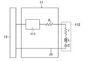
送信機11は、図2に示すように、切換制御機13に接続された送信回路111を有する。送信機11には送信アンテナ112が設けられており、その一端が第1抵抗R1を介して送信回路111に接続されている。送信アンテナ112の他端は第2抵抗R2を介して接地されている。また、送信機11には接地切替器113が設けられており、送信アンテナ112の他端は、その接地切替器113にも接続されて、その接地/非接地の切換が可能に構成されている。接地切替器113は切換制御機13に接続されている。
As shown in FIG. 2, the
ここで、接地切替器113により送信アンテナ112の他端が接地されていない場合、送信アンテナ112の前段に第1抵抗R1及び後段に第2抵抗R2がそれぞれ直列に接続された構成となるため、送信アンテナ112のインダクタンスをL、容量をC、及び抵抗をrとすると、このときこの第1アンテナ回路のQ1値は次式(1)の通りとなる。
Here, if the other end of the transmitting

一方、接地切替器113により送信アンテナ112の他端が接地されている場合、送信アンテナ112の前段に第1抵抗R1が直列に接続された構成となるため、このときの第2アンテナ回路のQ2値は次式(2)の通りとなる。
On the other hand, if the other end of the transmitting
つまり、第1抵抗R1及び第2抵抗R2は、このようにQ値の調整のための機能を果たす。第1抵抗R1は、それに加えて、送信アンテナ112のハーネスが短絡した場合における送信回路111を保護する機能を果たす。
That is, the first resistor R 1 and a second resistor R 2, thus performing the function for adjustment of the Q value. In addition, the first resistor R 1 functions to protect the
また、送信アンテナ112の信号送信エリアは磁界に比例する。さらに、図3に示すように、送信アンテナ112の磁界は次式(3)及び(4)の通りとなり、磁界は電流に比例する。
Further, the signal transmission area of the
ここで、I0は送信アンテナ112を流れる電流、Nは送信アンテナ112の巻数、Sは送信アンテナ112の開口面積、及びlは送信アンテナ112からの距離である。
Here, I 0 is the current flowing through the
そして、次式(5)のHminより大きい範囲が通信可能エリアとなる。 And the range larger than Hmin of following Formula (5) becomes a communicable area.
ここで、Hminは受信に必要な最小磁束密度、VTminは携帯装置20の最小受信電圧、fは受信周波数/送信周波数(例えば125kHz)、μ0は真空中の透磁率、NTは携帯装置20の受信アンテナの巻数、STは携帯装置20の受信アンテナの開口面積、QTは携帯装置20の受信アンテナ及び受信回路のQ値、及びαは発生磁界の方向と受信アンテナの面の法線方向の角度である。
Here, H min is the minimum magnetic flux density required for reception, V Tmin is the minimum reception voltage of the
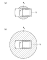
この送信機11は、印加される電圧が一定であるとすると、切換制御機13の制御で接地切替器113により送信アンテナ112の他端が接地されていない第1アンテナ回路が構成された場合には、図4(a)に示すように、相対的に小電流で、従って、弱磁界でリクエスト信号を車両Vを中心として狭い第1エリアA1(斜線部分、例えば半径1〜2m内))に送信する一方、切換制御機13の制御で接地切替器113により送信アンテナ112の他端が接地されている第2アンテナ回路が構成された場合には、図4(b)に示すように、相対的に大電流で、従って、強磁界でリクエスト信号を車両Vを中心として広い第2エリアA2(斜線部分、例えば半径1.2〜3m内)に送信するように構成されることとなる。つまり、解錠状態時に送信するリクエスト信号は、施錠状態時に送信するリクエスト信号よりも遠距離通信可能なものとなる。
In the
受信機12は、切換制御機13に接続された受信回路を有し、その受信回路に接続された受信アンテナが設けられている。
The
切換制御機13は、CPUやメモリを有するマイクロコンピュータで構成されている。
The
携帯装置20は、送信部及び受信部を有する。なお、携帯装置20内には、電力供給用のボタン電池等の電力源が設けられていてもよい。
The
実施形態1に係るパッシブキーレスエントリーシステムSでは、制御装置10は、送信機11が送信回路111により送信アンテナ112からリクエスト信号(例えばLF帯〜HF帯の数十kHz〜30MHz)を送信する。携帯装置20は、受信部がその制御装置10の送信機11からのリクエスト信号を受信したとき、送信部がパルス状の応答信号(例えば300MHz帯)を返信する。そして、制御装置10は、受信機12が携帯装置20からの応答信号を受信したとき、切換制御機13がその応答信号のIDを認証すると共に、その応答信号に基づいて、施錠状態と解錠状態との間で施錠/解錠状態を切換制御する。また、制御装置10は、切換制御機13が、ドアロック機構30からの情報に基づいてドアが施錠状態かどうか、ドア開閉センサ40からの情報に基づいてドアが閉まっているかどうか、及びイグニッションスイッチ50からの情報に基づいてキーが挿されているかどうかをそれぞれ検知する。
In the passive keyless entry system S according to the first embodiment, the
以下、制御装置10における施錠/解錠状態の切換制御について図5に示すフローチャートに基づいて詳しく説明する。この切換制御は切換制御機13にインストールされたコンピュータプログラムのCPUによる演算処理により実行されるものである。なお、このコンピュータプログラムはループプログラムである。
Hereinafter, the switching control of the locked / unlocked state in the
ステップA1では、キーが挿されていないかどうかを判断し、YESの場合にはステップA2に進み、NOの場合には再びステップA1に戻る。 In step A1, it is determined whether or not a key is inserted. If YES, the process proceeds to step A2, and if NO, the process returns to step A1.
ステップA2では、ドアが閉まっているかどうかを判断し、YESの場合にはステップA3に進み、NOの場合には再びステップA1に戻る。 In step A2, it is determined whether or not the door is closed. If YES, the process proceeds to step A3. If NO, the process returns to step A1.
ステップA3では、ドアが施錠状態かどうかを判断し、YESの場合にはステップA4に進み、NOの場合、つまり、ドアが解錠状態の場合にはステップA7に進む。 In step A3, it is determined whether or not the door is locked. If YES, the process proceeds to step A4. If NO, that is, if the door is unlocked, the process proceeds to step A7.
ステップA4では、接地切替器113により送信アンテナ112の他端を接地させずに、送信機11に第1アンテナ回路からリクエスト信号を送信させ、ステップA5に進む。このとき、小電流で、従って、図4(a)に示すように、弱磁界でリクエスト信号が車両Vを中心として狭い第1エリアA1に送信されることとなる。従って、施錠状態は通常は長時間の待機状態となることから、その間のリクエスト信号を低消費電流で送信することができる。
In step A4, the ground switch 113 does not ground the other end of the
ステップA5では、受信機12が携帯装置20からのID認証される応答信号を受信したかどうか、つまり、制御装置10がそれと対応付けられる携帯装置20と通信しているかどうかを判断し、YESの場合にはステップA6に進み、NOの場合にはステップA4に戻る。このとき、YESの場合は、弱磁界でリクエスト信号を送信している第1エリアA1内に存在する携帯装置20からのID認証される応答信号が受信されるという第1切換条件が満たされたということであり、これは、携帯装置20が図4(a)に示す第1エリアA1内に存在することとなった、つまり、携帯装置20を持った車両の所有者が車両に近づいたということである。
In step A5, it is determined whether or not the
ステップA6では、ドアの施錠状態を解錠状態に切り替えてステップA1に戻る。このとき、携帯装置20が狭い第1エリアA1内に存在することとなったときにドアの施錠状態を解錠状態に切り替えるので、セキュリティー性の向上を図ることができる。
In step A6, the door locking state is switched to the unlocking state, and the process returns to step A1. At this time, since the switching between the locked state of the door when it becomes the
一方、ステップA7では、接地切替器113により送信アンテナ112の他端を接地させて、送信機11に第2アンテナ回路からリクエスト信号を送信させ、ステップA8に進む。このとき、大電流で、従って、図4(b)に示すように、強磁界でリクエスト信号が車両Vを中心として広い第2エリアA2に送信されることとなる。
On the other hand, in step A7, the other end of the
ステップA8では、受信機12が携帯装置20からのID認証される応答信号を受信した後、さらに同じID認証される応答信号を受信しないかどうかを判断し、YESの場合にはステップA9に進み、NOの場合にはステップA7に戻る。このとき、YESの場合は、強磁界でリクエスト信号を送信している第2エリアA2内に存在する携帯装置20からのID認証される応答信号が受信されないという第2切換条件が満たされたということであり、これは、携帯装置20が図4(b)に示す第2エリアA2外に存在することとなる、つまり、携帯装置20を持った車両の所有者が車両から遠ざかったということである。この第2切換条件は第1切換条件の反対条件とは別の条件である。なお、このステップA8では、受信機12が携帯装置20からのID認証される応答信号を受信した後、さらに同じID認証される応答信号を受信しないかどうかを判断するが、その応答信号の受信前に携帯装置20の所有者が第2エリアA2外に走り出てしまうことがないように、第2エリアA2を広く設定しておくことが好ましい。このように第2エリアA2を広く設定しておけば、運転席以外からの降車が可能であり、運転席から降車してトランクへ荷物を取りに行く間に施錠されるのを防止することもできる。また、キーを車室内に置き忘れ、その状態で不用意に施錠がなされないように車室内のエリアは通信可能にしておくことが好ましい。
In step A8, after the
ステップA9では、ドアの解錠状態を施錠状態に切り替えてステップA1に戻る。 In step A9, the unlocked state of the door is switched to the locked state, and the process returns to step A1.
この実施形態1に係るパッシブキーレスエントリーシステムSによれば、施錠状態時には、第1切換条件が満たされたとき、つまり、携帯装置20が狭い第1エリアA1内に存在することとなったことを検知したときに解錠状態に切り替え、一方、解錠状態時には、第1切換条件の反対条件とは別の第2切換条件が満たされたとき、つまり、携帯装置20が第1エリアA1を含むより広い範囲の第2エリアA2外に存在することとなったことを検知したときに施錠状態に切り替えるので、施錠状態から解錠状態への切換及び解錠状態から施錠状態への切換のそれぞれで境界を有し、そのため単一の境界条件でスイッチング状態の切り替え制御を行う場合のように境界条件付近で切り替えが連続して繰り返されることはなく、従って、第1及び第2切換条件いずれの境界条件においても施錠/解錠状態の切り替えを安定して行うことができる。しかも、この実施形態1に係るパッシブキーレスエントリーシステムSは、送信アンテナ112のアンテナ回路の回路構成が比較的簡単であることから、かかる制御を低コストで行うことができる。
According to the passive keyless entry system S according to this embodiment 1, it at the time of the locked state, when the first switching condition is met, which was decided that the
(実施形態2)
実施形態2に係るパッシブキーレスエントリー(PKE:Passive Keyless Entry)システムSの概略構成は図1に示す実施形態1のものと同一である。なお、実施形態1と同一名称の部分は実施形態1と同一符号で示す。
(Embodiment 2)
A schematic configuration of a passive keyless entry (PKE) system S according to the second embodiment is the same as that of the first embodiment shown in FIG. In addition, the part of the same name as Embodiment 1 is shown with the same code | symbol as Embodiment 1. FIG.
実施形態2に係るパッシブキーレスエントリーシステムSでは、送信機11は、図6に示すように、切換制御機13に接続された送信回路111を有する。送信機11には送信アンテナ112が設けられており、その一端が第1抵抗R1を介して送信回路111に接続されている。送信アンテナ112の他端は接地されている。また、送信回路111には電圧可変回路114が接続されており、その電圧可変回路114は切換制御機13に接続されている。
In the passive keyless entry system S according to the second embodiment, the
この送信機11は、切換制御機13の制御で電圧可変回路114により送信回路111から送信アンテナ112に相対的に低電圧が印加された場合には、小電流で、従って、弱磁界でリクエスト信号を狭い第1エリアA1(斜線部分、例えば半径1〜2m内)に送信する一方、切換制御機13の制御で電圧可変回路114により送信回路111から送信アンテナ112に相対的に高電圧が印加された場合には、大電流で、従って、強磁界でリクエスト信号を広い第2エリアA2(斜線部分、例えば半径1.2〜3m内)に送信するように構成されることとなる。つまり、解錠状態時に送信するリクエスト信号は、施錠状態時に送信するリクエスト信号よりも遠距離通信可能なものとなっている。
When a relatively low voltage is applied from the
実施形態2に係るパッシブキーレスエントリーシステムSでは、制御装置10は、送信機11が送信回路111により送信アンテナ112からリクエスト信号(例えばLF帯〜HF帯の数十kHz〜30MHz)を送信する。携帯装置20は、受信部がその制御装置10の送信機11からのリクエスト信号を受信したとき、送信部がパルス状の応答信号(例えば300MHz帯)を返信する。そして、制御装置10は、受信機12が携帯装置20からの応答信号を受信したとき、切換制御機13がその応答信号のIDを認証すると共に、その応答信号に基づいて、施錠状態と解錠状態との間で施錠/解錠状態を切換制御する。また、制御装置10は、切換制御機13が、ドアロック機構30からの情報に基づいてドアが施錠状態かどうか、ドア開閉センサ40からの情報に基づいてドアが閉まっているかどうか、及びイグニッションスイッチ50からの情報に基づいてキーが挿されているかどうかをそれぞれ検知する。
In the passive keyless entry system S according to the second embodiment, the
以下、制御装置10における施錠/解錠状態の切換制御について図7に示すフローチャートに基づいて詳しく説明する。
Hereinafter, the switching control of the locked / unlocked state in the
ステップB1では、キーが挿されていないかどうかを判断し、YESの場合にはステップB2に進み、NOの場合には再びステップB1に戻る。 In Step B1, it is determined whether or not a key is inserted. If YES, the process proceeds to Step B2, and if NO, the process returns to Step B1 again.
ステップB2では、ドアが閉まっているかどうかを判断し、YESの場合にはステップB3に進み、NOの場合には再びステップB1に戻る。 In step B2, it is determined whether or not the door is closed. If YES, the process proceeds to step B3. If NO, the process returns to step B1 again.
ステップB3では、ドアが施錠状態かどうかを判断し、YESの場合にはステップB4に進み、NOの場合、つまり、ドアが解錠状態の場合にはステップB7に進む。 In step B3, it is determined whether or not the door is locked. If YES, the process proceeds to step B4. If NO, that is, if the door is unlocked, the process proceeds to step B7.
ステップB4では、電圧可変回路114により送信回路111から送信アンテナ112に低電圧を印加することにより送信機11に弱磁界でリクエスト信号を送信させ、ステップB5に進む。このとき、小電流で、従って、図4(a)に示すように、弱磁界でリクエスト信号が車両Vを中心として狭い第1エリアA1に送信されることとなる。従って、施錠状態は通常は長時間の待機状態となることから、その間のリクエスト信号を低消費電流で送信することができる。
In step B4, the
ステップB5では、受信機12が携帯装置20からのID認証される応答信号を受信したかどうか、つまり、制御装置10がそれと対応付けられる携帯装置20と通信しているかどうかを判断し、YESの場合にはステップB6に進み、NOの場合にはステップB4に戻る。このとき、YESの場合は、弱磁界でリクエスト信号を送信している第1エリアA1内に存在する携帯装置20からのID認証される応答信号が受信されるという第1切換条件が満たされたということであり、これは、携帯装置20が図4(a)に示す第1エリアA1内に存在することとなった、つまり、携帯装置20を持った車両の所有者が車両に近づいたということである。
In step B5, it is determined whether or not the
ステップB6では、ドアの施錠状態を解錠状態に切り替えてステップB1に戻る。このとき、携帯装置20が狭い第1エリアA1内に存在することとなったときにドアの施錠状態を解錠状態に切り替えるので、セキュリティー性の向上を図ることができる。
In step B6, the door locking state is switched to the unlocking state, and the process returns to step B1. At this time, since the switching between the locked state of the door when it becomes the
一方、ステップB7では、電圧可変回路114により送信回路111から送信アンテナ112に高電圧を印加することにより送信機11に強磁界でリクエスト信号を送信させ、ステップB8に進む。このとき、大電流で、従って、図4(b)に示すように、強磁界でリクエスト信号が車両Vを中心として広い第2エリアA2に送信されることとなる。
On the other hand, in step B7, the
ステップB8では、受信機12が携帯装置20からのID認証される応答信号を受信した後、さらに同じID認証される応答信号を受信しないかどうかを判断し、YESの場合にはステップB9に進み、NOの場合にはステップB7に戻る。このとき、YESの場合は、強磁界でリクエスト信号を送信している第2エリアA2内に存在する携帯装置20からのID認証される応答信号が受信されないという第2切換条件が満たされたということであり、これは、携帯装置20が図4(b)に示す第2エリアA2外に存在することとなる、つまり、携帯装置20を持った車両の所有者が車両から遠ざかったということである。この第2切換条件は第1切換条件の反対条件とは別の条件である。なお、このステップB8では、受信機12が携帯装置20からのID認証される応答信号を受信した後、さらに同じID認証される応答信号を受信しないかどうかを判断するが、その応答信号の受信前に携帯装置20の所有者が第2エリアA2外に走り出てしまうことがないように、第2エリアA2を広く設定しておくことが好ましい。このように第2エリアA2を広く設定しておけば、運転席以外からの降車が可能であり、運転席から降車してトランクへ荷物を取りに行く間に施錠されるのを防止することもできる。また、キーを車室内に置き忘れ、その状態で不用意に施錠がなされないように車室内のエリアは通信可能にしておくことが好ましい。
In step B8, after the
ステップB9では、ドアの解錠状態を施錠状態に切り替えてステップB1に戻る。 In step B9, the unlocked state of the door is switched to the locked state, and the process returns to step B1.
その他の構成、作用効果については実施形態1と同一である。 Other configurations and operational effects are the same as those of the first embodiment.
(実施形態3)
実施形態3に係るパッシブキーレスエントリー(PKE:Passive Keyless Entry)システムSの概略構成は図1に示す実施形態1のものと同一である。なお、実施形態1と同一名称の部分は実施形態1と同一符号で示す。
(Embodiment 3)
The schematic configuration of a passive keyless entry (PKE) system S according to the third embodiment is the same as that of the first embodiment shown in FIG. In addition, the part of the same name as Embodiment 1 is shown with the same code | symbol as Embodiment 1. FIG.
実施形態3に係るパッシブキーレスエントリーシステムSでは、送信機11は、図8に示すように、切換制御機13に接続された送信回路111を有する。送信機11には送信アンテナ112が設けられており、その一端が第1抵抗R1を介して送信回路111に接続されている。送信アンテナ112の他端は接地されている。なお、実施形態1と同一名称の部分は実施形態1と同一符号で示す。
In the passive keyless entry system S according to the third embodiment, the
実施形態3に係るパッシブキーレスエントリーシステムSでは、制御装置10は、送信機11が送信回路111により送信アンテナ112からリクエスト信号(例えばLF帯〜HF帯の数十kHz〜30MHz)を送信する。携帯装置20は、受信部がその制御装置10の送信機11からのリクエスト信号を受信したとき、送信部がパルス状の応答信号(例えば300MHz帯)を返信する。そして、制御装置10は、受信機12が携帯装置20からの応答信号を受信したとき、切換制御機13がその応答信号のIDを認証すると共に、その応答信号に基づいて、施錠状態と解錠状態との間で施錠/解錠状態を切換制御する。また、制御装置10は、切換制御機13が、ドアロック機構30からの情報に基づいてドアが施錠状態かどうか、ドア開閉センサ40からの情報に基づいてドアが閉まっているかどうか、及びイグニッションスイッチ50からの情報に基づいてキーが挿されているかどうかをそれぞれ検知する。
In the passive keyless entry system S according to the third embodiment, the
以下、制御装置10における施錠/解錠状態の切換制御について図9に示すフローチャートに基づいて詳しく説明する。
Hereinafter, the switching control of the locked / unlocked state in the
ステップC1では、キーが挿されていないかどうかを判断し、YESの場合にはステップC2に進み、NOの場合には再びステップC1に戻る。 In Step C1, it is determined whether or not a key is inserted. If YES, the process proceeds to Step C2, and if NO, the process returns to Step C1 again.
ステップC2では、ドアが閉まっているかどうかを判断し、YESの場合にはステップC3に進み、NOの場合には再びステップC1に戻る。 In Step C2, it is determined whether or not the door is closed. If YES, the process proceeds to Step C3. If NO, the process returns to Step C1.
ステップC3では、ドアが施錠状態かどうかを判断し、YESの場合にはステップC4に進み、NOの場合、つまり、ドアが解錠状態の場合にはステップC9に進む。 In Step C3, it is determined whether or not the door is locked. If YES, the process proceeds to Step C4. If NO, that is, if the door is unlocked, the process proceeds to Step C9.
ステップC4では、リクエスト信号を送信させてステップC5に進む。 In step C4, the request signal is transmitted and the process proceeds to step C5.
ステップC5では、受信機12が携帯装置20からのID認証される応答信号を受信したかどうか、つまり、制御装置10がそれと対応付けられる携帯装置20と通信しているかどうかを判断し、YESの場合にはステップC6に進み、NOの場合にはステップC10に進む。
In step C5, it is determined whether or not the
ステップC6では、積算受信回数に1を加えてステップC7に進む。 In step C6, 1 is added to the cumulative number of receptions and the process proceeds to step C7.
ステップC7では、積算受信回数が規定受信回数(例えば3回)に一致するかどうかを判断し、YESの場合にはステップC8に進み、NOの場合にはステップC4に戻る。このとき、YESの場合は、ID認証される応答信号の積算受信回数が規定受信回数に一致する、つまり、ID認証される応答信号が連続して規定受信回数だけ受信されるという第1切換条件が満たされたということである。 In step C7, it is determined whether or not the cumulative number of receptions matches a specified number of receptions (for example, three times). If YES, the process proceeds to step C8, and if NO, the process returns to step C4. At this time, in the case of YES, the first switching condition in which the cumulative number of receptions of the ID-authenticated response signal matches the specified number of receptions, that is, the ID-authenticated response signal is continuously received by the specified number of receptions. Is satisfied.
ステップC8では、ドアの施錠状態を解錠状態に切り替えてステップC9に進む。 In step C8, the door locking state is switched to the unlocking state, and the process proceeds to step C9.
ステップC9では、積算受信回数に0にリセットしてステップC1に戻る。 In step C9, the cumulative number of receptions is reset to 0 and the process returns to step C1.
一方、ステップC10では、リクエスト信号を送信させてステップC11に進む。 On the other hand, in step C10, the request signal is transmitted and the process proceeds to step C11.
ステップC11では、受信機12が携帯装置20からのID認証される応答信号を受信した後、さらに同じID認証される応答信号を受信しなくなったかどうかを判断し、YESの場合にはステップC12に進み、NOの場合には再びステップC10に戻る。このとき、YESの場合は、ID認証される応答信号が受信されなくなった、つまり、一度でもID認証される応答信号が受信されないという第2切換条件が満たされたということである。この第2切換条件は第1切換条件の反対条件とは別の条件である。
In step C11, after the
ステップC12では、ドアの解錠状態を施錠状態に切り替えてステップC1に戻る。 In Step C12, the unlocked state of the door is switched to the locked state, and the process returns to Step C1.
その他の構成は実施形態1と同一である。 Other configurations are the same as those of the first embodiment.
実施形態3に係るパッシブキーレスエントリーシステムSによれば、施錠状態時には、所定の第1切換条件が満たされたとき、つまり、ID認証される応答信号が連続して規定受信回数だけ受信されたときに解錠状態に切り替え、一方、解錠状態時には、第1切換条件の反対条件とは別の第2切換条件が満たされたとき、つまり、一度でもID認証される応答信号が受信されないときに施錠状態に切り替えるので、施錠状態から解錠状態への切換及び解錠状態から施錠状態への切換のそれぞれで境界条件を有し、そのため単一の境界条件でスイッチング状態の切り替え制御を行う場合のように境界条件付近で切り替えが連続して繰り返されることはなく、従って、第1及び第2切換条件いずれの境界条件においても施錠/解錠状態の切り替えを安定して行うことができる。 According to the passive keyless entry system S according to the third embodiment, in the locked state, when a predetermined first switching condition is satisfied, that is, when a response signal that is ID-authenticated is continuously received a predetermined number of times. In the unlocked state, on the other hand, when the second switching condition different from the condition opposite to the first switching condition is satisfied, that is, when the response signal for ID authentication is not received even once. Since switching to the locked state, there is a boundary condition in each of switching from the locked state to the unlocked state and switching from the unlocked state to the locked state, and therefore when switching control of the switching state is performed with a single boundary condition Thus, the switching is not repeated continuously in the vicinity of the boundary condition, and therefore the locked / unlocked state is switched under the boundary condition of both the first and second switching conditions. It can be performed in a stable manner.
(その他の実施形態)
上記実施形態1〜3では、ドアロック機構30のパッシブキーレスエントリーシステムSとしたが、特にこれに限定されるものではなく、狭いエリア内で解除して広いエリア外でセットするセキュリティシステム、狭いエリア内でエンジン始動して広いエリア外でエンジン停止(ターボタイマー)するエンジンスタータ、ミラーの開閉、ウインドウガラスの開閉、エアコンのON/OFF等のその他の車両用電装機器のスイッチングシステムであってもよく、また、車両用電装機器以外のオフィスなどの入退室管理、家屋などの玄関の施錠/解錠、マンションのエントランスの自動ドア等のスイッチングシステムであってもよく、さらに、車両用及びその他用途でのRFID(電波による個体識別)のスイッチングシステムであってもよい。
(Other embodiments)
In the first to third embodiments, the passive keyless entry system S of the
上記実施形態1及び2では、携帯装置20が狭い第1エリアA1内に存在することとなったことを第1切換条件とし、そして、携帯装置20が第1エリアA1を含むより広い範囲の第2エリアA2外に存在することとなったことを第1切換条件の反対条件とは別の第2切換条件とした構成とし、また、上記実施形態3では、ID認証される応答信号が連続して規定受信回数だけ受信されたことを第1切換条件とし、そして、一度でもID認証される応答信号が受信されないことを第1切換条件の反対条件とは別の第2切換条件とした構成としたが、特にこれらに限定されるものではなく、その他の第1切換条件、及び第1切換条件の反対条件とは別の第2切換条件の組合せの構成であってもよい。
In the first and second embodiments, it became the
本発明はスイッチングシステムについて有用である。 The present invention is useful for switching systems.
S パッシブキーレスエントリーシステム(スイッチングシステム)
10 制御装置
11 送信機
12 受信機
13 切換制御機
20 携帯装置
30 ドアロック機構(車両用電装機器)
40 ドア開閉センサ
50 イグニッションスイッチ
111 送信回路
112 送信アンテナ
113 接地切替器
114 電圧可変回路
S Passive keyless entry system (switching system)
DESCRIPTION OF
40 Door open /
Claims (4)
上記制御装置の上記送信機からのリクエスト信号を受信したときに応答信号を返信する携帯装置と、
を備えたスイッチングシステムであって、
上記制御装置は、上記携帯装置からの応答信号を受信する受信機と、該受信機で受信した応答信号に基づいて第1スイッチング状態と第2スイッチング状態との間でスイッチング状態を切換制御する切換制御機と、をさらに有し、
上記制御装置の送信機は、第1スイッチング状態時には、該制御装置を含む第1エリア内に相対的に弱磁界でリクエスト信号を送信し、一方、第2スイッチング状態時には、第1エリアを含むより広い範囲の第2エリア内に相対的に強磁界でリクエスト信号を送信するように構成され、
上記制御装置の上記切換制御機は、第1スイッチング状態時には、上記携帯装置が第1エリア内に存在することとなったことを検知したときに、第2スイッチング状態にスイッチング状態を切り替え、一方、第2スイッチング状態時には、上記携帯装置が第2エリア外に存在することとなったことを検知したときに、第1スイッチング状態にスイッチング状態を切り替えるように構成されているスイッチングシステム。 A control device having a transmitter for transmitting a request signal;
A portable device that returns a response signal when receiving a request signal from the transmitter of the control device;
A switching system comprising:
The control device includes a receiver that receives a response signal from the portable device, and a switch that switches and controls a switching state between a first switching state and a second switching state based on the response signal received by the receiver. A controller, and
The transmitter of the control device transmits a request signal with a relatively weak magnetic field in the first area including the control device in the first switching state, and includes the first area in the second switching state. Configured to transmit a request signal in a relatively strong magnetic field within a wide second area;
In the first switching state , the switching controller of the control device switches the switching state to the second switching state when detecting that the portable device is present in the first area, A switching system configured to switch the switching state to the first switching state when it is detected that the portable device is located outside the second area in the second switching state .
上記制御装置の上記切換制御機は、上記送信機に、第2スイッチング状態時に送信させるリクエスト信号を、第1スイッチング状態時に送信させるリクエスト信号よりも遠距離通信可能なものとするように構成されているスイッチングシステム。 The switching system according to claim 1 , wherein
The switching controller of the control device is configured to enable a long-distance communication of a request signal transmitted to the transmitter in the second switching state than a request signal transmitted in the first switching state. Switching system.
上記制御装置が車載されて車両用電装機器のスイッチング状態を切換制御するスイッチングシステム。 In the switching system according to claim 1 or 2 ,
A switching system in which the control device is mounted on the vehicle and switches and controls the switching state of the vehicle electrical equipment.
上記車両用電装機器がドアロック機構であって、第1スイッチング状態が施錠状態及び第2スイッチング状態が解錠状態であるスイッチングシステム。 The switching system according to claim 3 , wherein
The vehicle electrical device is a door lock mechanism, wherein the first switching state is a locked state and the second switching state is an unlocked state.
Priority Applications (1)
| Application Number | Priority Date | Filing Date | Title |
|---|---|---|---|
| JP2009247568A JP5590482B2 (en) | 2009-10-28 | 2009-10-28 | Switching system |
Applications Claiming Priority (1)
| Application Number | Priority Date | Filing Date | Title |
|---|---|---|---|
| JP2009247568A JP5590482B2 (en) | 2009-10-28 | 2009-10-28 | Switching system |
Publications (3)
| Publication Number | Publication Date |
|---|---|
| JP2011094345A JP2011094345A (en) | 2011-05-12 |
| JP2011094345A5 JP2011094345A5 (en) | 2012-06-07 |
| JP5590482B2 true JP5590482B2 (en) | 2014-09-17 |
Family
ID=44111561
Family Applications (1)
| Application Number | Title | Priority Date | Filing Date |
|---|---|---|---|
| JP2009247568A Expired - Fee Related JP5590482B2 (en) | 2009-10-28 | 2009-10-28 | Switching system |
Country Status (1)
| Country | Link |
|---|---|
| JP (1) | JP5590482B2 (en) |
Families Citing this family (2)
| Publication number | Priority date | Publication date | Assignee | Title |
|---|---|---|---|---|
| EP2813963B1 (en) * | 2012-02-09 | 2017-07-05 | NEC Solution Innovators, Ltd. | Information processing system |
| JP6003938B2 (en) * | 2014-03-28 | 2016-10-05 | トヨタ自動車株式会社 | Electronic key system |
Family Cites Families (3)
| Publication number | Priority date | Publication date | Assignee | Title |
|---|---|---|---|---|
| JP2003213999A (en) * | 2002-01-25 | 2003-07-30 | Altia Co Ltd | Wireless door locking device |
| JP2006249719A (en) * | 2005-03-09 | 2006-09-21 | Yupiteru Ind Co Ltd | On-vehicle machine remote control system and on-vehicle machine remote control method |
| JP4561612B2 (en) * | 2005-11-25 | 2010-10-13 | 株式会社デンソー | Vehicle door control system |
-
2009
- 2009-10-28 JP JP2009247568A patent/JP5590482B2/en not_active Expired - Fee Related
Also Published As
| Publication number | Publication date |
|---|---|
| JP2011094345A (en) | 2011-05-12 |
Similar Documents
| Publication | Publication Date | Title |
|---|---|---|
| JP3899505B2 (en) | Wireless device | |
| JP4612173B2 (en) | Hand-free access device and engine starter for automobile | |
| EP0965710B1 (en) | Vehicle control system | |
| US9126564B2 (en) | Communication apparatus for vehicle | |
| US7305284B2 (en) | Remote control system and method for vehicle | |
| JP5322082B2 (en) | VEHICLE ACCESS CIRCUIT AND METHOD FOR OPERATING VEHICLE ACCESS CIRCUIT | |
| JP3668729B2 (en) | In-vehicle device remote control system | |
| JP2005146529A (en) | Keyless entry system | |
| JP3714129B2 (en) | Door opener | |
| US20210370877A1 (en) | Vehicular access system using nfc reader in door handle | |
| JPH112053A (en) | Passive entry control system for vehicle | |
| EP1969566B1 (en) | Method for passive keyless entry of a motor vehicle especially of an industrial vehicle | |
| EP1384844A2 (en) | Door handle for a vehicle | |
| JP3659583B2 (en) | In-vehicle device remote control system | |
| WO2021131713A9 (en) | Smart key accommodation case for vehicle | |
| JP5590482B2 (en) | Switching system | |
| JP5629596B2 (en) | Vehicle wireless communication system | |
| JP4297934B2 (en) | Vehicle communication device | |
| JP3899912B2 (en) | Door opener | |
| JP3582384B2 (en) | In-vehicle equipment remote control device | |
| JP2008069629A (en) | Access circuit for vehicle | |
| US20210094510A1 (en) | Vehicle having an access management system and method for authorizing access to a vehicle | |
| JP2015113613A (en) | Locking-unlocking control device and system | |
| JP4613788B2 (en) | Vehicle door unlock control device | |
| JP2004132069A (en) | Controller for door lock mechanism |
Legal Events
| Date | Code | Title | Description |
|---|---|---|---|
| RD02 | Notification of acceptance of power of attorney |
Free format text: JAPANESE INTERMEDIATE CODE: A7422 Effective date: 20120321 |
|
| A521 | Written amendment |
Free format text: JAPANESE INTERMEDIATE CODE: A523 Effective date: 20120416 |
|
| A621 | Written request for application examination |
Free format text: JAPANESE INTERMEDIATE CODE: A621 Effective date: 20120829 |
|
| A977 | Report on retrieval |
Free format text: JAPANESE INTERMEDIATE CODE: A971007 Effective date: 20130625 |
|
| A131 | Notification of reasons for refusal |
Free format text: JAPANESE INTERMEDIATE CODE: A131 Effective date: 20131126 |
|
| A521 | Written amendment |
Free format text: JAPANESE INTERMEDIATE CODE: A523 Effective date: 20140107 |
|
| A711 | Notification of change in applicant |
Free format text: JAPANESE INTERMEDIATE CODE: A711 Effective date: 20140516 |
|
| TRDD | Decision of grant or rejection written | ||
| A521 | Written amendment |
Free format text: JAPANESE INTERMEDIATE CODE: A821 Effective date: 20140516 |
|
| A01 | Written decision to grant a patent or to grant a registration (utility model) |
Free format text: JAPANESE INTERMEDIATE CODE: A01 Effective date: 20140708 |
|
| A711 | Notification of change in applicant |
Free format text: JAPANESE INTERMEDIATE CODE: A711 Effective date: 20140711 |
|
| A61 | First payment of annual fees (during grant procedure) |
Free format text: JAPANESE INTERMEDIATE CODE: A61 Effective date: 20140718 |
|
| A521 | Written amendment |
Free format text: JAPANESE INTERMEDIATE CODE: A821 Effective date: 20140711 |
|
| R150 | Certificate of patent or registration of utility model |
Ref document number: 5590482 Country of ref document: JP Free format text: JAPANESE INTERMEDIATE CODE: R150 |
|
| LAPS | Cancellation because of no payment of annual fees |