JP5589275B2 - Power storage device and manufacturing method thereof - Google Patents
Power storage device and manufacturing method thereof Download PDFInfo
- Publication number
- JP5589275B2 JP5589275B2 JP2008278362A JP2008278362A JP5589275B2 JP 5589275 B2 JP5589275 B2 JP 5589275B2 JP 2008278362 A JP2008278362 A JP 2008278362A JP 2008278362 A JP2008278362 A JP 2008278362A JP 5589275 B2 JP5589275 B2 JP 5589275B2
- Authority
- JP
- Japan
- Prior art keywords
- metal case
- resin frame
- temperature sensor
- power storage
- storage device
- Prior art date
- Legal status (The legal status is an assumption and is not a legal conclusion. Google has not performed a legal analysis and makes no representation as to the accuracy of the status listed.)
- Active
Links
- 238000003860 storage Methods 0.000 title claims description 40
- 238000004519 manufacturing process Methods 0.000 title claims description 9
- 229910052751 metal Inorganic materials 0.000 claims description 181
- 239000002184 metal Substances 0.000 claims description 181
- 229920005989 resin Polymers 0.000 claims description 122
- 239000011347 resin Substances 0.000 claims description 122
- 238000001514 detection method Methods 0.000 claims description 38
- 238000000576 coating method Methods 0.000 claims description 31
- 239000011248 coating agent Substances 0.000 claims description 29
- 238000000465 moulding Methods 0.000 claims description 22
- 238000000034 method Methods 0.000 claims description 5
- 239000011255 nonaqueous electrolyte Substances 0.000 description 34
- 238000001816 cooling Methods 0.000 description 19
- 238000004070 electrodeposition Methods 0.000 description 12
- 238000010248 power generation Methods 0.000 description 8
- 238000009413 insulation Methods 0.000 description 7
- 238000004381 surface treatment Methods 0.000 description 7
- 230000007797 corrosion Effects 0.000 description 4
- 238000005260 corrosion Methods 0.000 description 4
- 238000001746 injection moulding Methods 0.000 description 4
- 230000006866 deterioration Effects 0.000 description 3
- 230000020169 heat generation Effects 0.000 description 3
- 230000008961 swelling Effects 0.000 description 3
- 239000002390 adhesive tape Substances 0.000 description 2
- 239000003792 electrolyte Substances 0.000 description 2
- 239000003973 paint Substances 0.000 description 2
- 238000009423 ventilation Methods 0.000 description 2
- 229910000838 Al alloy Inorganic materials 0.000 description 1
- 230000032683 aging Effects 0.000 description 1
- 230000015572 biosynthetic process Effects 0.000 description 1
- 239000003990 capacitor Substances 0.000 description 1
- 150000001768 cations Chemical class 0.000 description 1
- 238000005536 corrosion prevention Methods 0.000 description 1
- 238000007599 discharging Methods 0.000 description 1
- 230000005611 electricity Effects 0.000 description 1
- 239000000446 fuel Substances 0.000 description 1
- 230000017525 heat dissipation Effects 0.000 description 1
- 238000002347 injection Methods 0.000 description 1
- 239000007924 injection Substances 0.000 description 1
- 239000011810 insulating material Substances 0.000 description 1
- 239000007788 liquid Substances 0.000 description 1
- 238000003754 machining Methods 0.000 description 1
- 239000000463 material Substances 0.000 description 1
- 239000012528 membrane Substances 0.000 description 1
- 230000005855 radiation Effects 0.000 description 1
- 125000006850 spacer group Chemical group 0.000 description 1
- 239000010935 stainless steel Substances 0.000 description 1
- 229910001220 stainless steel Inorganic materials 0.000 description 1
- 239000000126 substance Substances 0.000 description 1
- 229920003002 synthetic resin Polymers 0.000 description 1
- 239000000057 synthetic resin Substances 0.000 description 1
- XLYOFNOQVPJJNP-UHFFFAOYSA-N water Substances O XLYOFNOQVPJJNP-UHFFFAOYSA-N 0.000 description 1
- 238000003466 welding Methods 0.000 description 1
- 238000004804 winding Methods 0.000 description 1
Images


Classifications
-
- Y—GENERAL TAGGING OF NEW TECHNOLOGICAL DEVELOPMENTS; GENERAL TAGGING OF CROSS-SECTIONAL TECHNOLOGIES SPANNING OVER SEVERAL SECTIONS OF THE IPC; TECHNICAL SUBJECTS COVERED BY FORMER USPC CROSS-REFERENCE ART COLLECTIONS [XRACs] AND DIGESTS
- Y02—TECHNOLOGIES OR APPLICATIONS FOR MITIGATION OR ADAPTATION AGAINST CLIMATE CHANGE
- Y02E—REDUCTION OF GREENHOUSE GAS [GHG] EMISSIONS, RELATED TO ENERGY GENERATION, TRANSMISSION OR DISTRIBUTION
- Y02E60/00—Enabling technologies; Technologies with a potential or indirect contribution to GHG emissions mitigation
- Y02E60/10—Energy storage using batteries
Landscapes
- Battery Mounting, Suspending (AREA)
- Secondary Cells (AREA)
Description
本発明は、金属ケースを用いた蓄電装置及びその製造方法に関するものである。 The present invention relates to a power storage device using a metal case and a method for manufacturing the same.
電池外装ケースとして金属ケースを用いた大型の非水電解質二次電池を組電池に用いる場合、従来は、金属ケースの周囲を熱収縮チューブで覆い、一対の合成樹脂製の枠体で挟んだ電池を複数個隣接させて並べ、両側から挟持することがあった(例えば、特許文献1参照。)。組電池にこのような枠体を用いるのは、複数の電池を枠体を介して並べることにより、各電池間に冷却のための隙間をあけるようにするためである。また、1個の組電池ケース内に電池を複数個収納するのではなく、このように各電池を枠体で挟んでから組み合わせるのは、組電池に使用する電池の個数がユーザーや製品ごと等で異なるので、電池個数の相違にフレキシブルに対応できるようにするためである。 When using a large nonaqueous electrolyte secondary battery using a metal case as a battery outer case for an assembled battery, the battery is conventionally covered with a heat-shrinkable tube and sandwiched between a pair of synthetic resin frames. A plurality of them are arranged adjacent to each other and sandwiched from both sides (see, for example, Patent Document 1). The reason why such a frame body is used for the assembled battery is to arrange a plurality of batteries through the frame body so that a gap for cooling is provided between the batteries. In addition, a plurality of batteries are not housed in one assembled battery case, and the batteries are assembled in such a manner that they are sandwiched between frames in this way. Therefore, it is possible to flexibly cope with the difference in the number of batteries.
なお、非水電解質二次電池の金属ケースを熱収縮チューブで覆うのは、この金属ケースの外表面の絶縁と防食のためであるが、このような熱収縮チューブに代えて、金属ケースの外表面を電着塗装による絶縁塗装膜で覆うようにすることもできる(例えば、特許文献2参照。)。電着塗装による絶縁塗装膜は、電着槽で塗膜を形成後に乾燥して焼き付け処理を行ったものなので、熱収縮チューブに比べて膜厚が薄く放熱が容易な絶縁材となる。 The reason why the metal case of the nonaqueous electrolyte secondary battery is covered with the heat shrinkable tube is to insulate and prevent corrosion of the outer surface of the metal case. The surface can be covered with an insulating coating film by electrodeposition coating (see, for example, Patent Document 2). Since the insulating coating film by electrodeposition coating is a coating film formed in an electrodeposition tank and then dried and baked, it becomes an insulating material having a smaller film thickness and easier heat dissipation than a heat-shrinkable tube.
ここで、電池は、充放電時に熱を発し、非水電解質二次電池は、この発熱によって高温になることがあるので、上記のように電池間に冷却のための隙間をあけるだけでなく、各電池に温度センサを取り付けて、この温度センサが検出した電池温度を監視する場合がある。そして、上記組電池の場合には、従来は、例えば樹脂製の取付具に温度センサを組み込み、枠体にこの取付具を取り付けることにより、非水電解質二次電池の金属ケースにおける熱収縮チューブに覆われていない底面に温度センサの検知部が当接するようにしていた。
ところが、電池は、幅の狭い角形の金属ケースの場合は最も面積の広い側面が、また、円筒形の金属ケースの場合は円筒側面が内部の発電要素と最も接近するので、これらの側面の中央部(円筒形の場合は軸方向の中央部)の温度が最も高くなり正確な電池温度を示すことになる。このため、金属ケースの底面に温度センサの検知部を当接させても、温度上昇が側面に比べて少なくなるので、正確な電池温度を検出することができないという問題があった。 However, in the case of a narrow rectangular metal case, the battery has the widest side surface, and in the case of a cylindrical metal case, the cylindrical side surface is closest to the internal power generation element. The temperature of the portion (in the case of a cylindrical shape, the central portion in the axial direction) is the highest, indicating an accurate battery temperature. For this reason, even if the detection part of the temperature sensor is brought into contact with the bottom surface of the metal case, the temperature rise is less than that on the side surface, so that there is a problem that the accurate battery temperature cannot be detected.
また、熱収縮チューブに代えて金属ケースの外表面を電着塗装による絶縁塗装膜で覆った場合には、金属ケースの底面も側面も同じ薄い絶縁塗装膜で覆われるだけなので、温度センサの検知部をこの金属ケースの側面に当接させることにより、さらに正確な電池温度の検出を行うようにすることができる。しかしながら、例えば幅の狭い角形の金属ケースを用いた場合、各電池の最も面積の広い側面同士を向かい合わせに並べて組電池を構成するのが一般的であるため、この電池間の狭い隙間を通して最も面積の広い側面の中央部に温度センサを取り付けることが困難になるという問題が発生する。なぜなら、組電池の組み立て後に狭い隙間を通して温度センサを取り付けることが困難であるだけでなく、一対の枠体は組電池を組み立てたときに初めて電池と一体になるので、事前に枠体に温度センサの取付具を取り付けておいても、組電池の組み立て後に温度センサの検知部を正確に金属ケースの側面に当接させるようにすることが困難だからである。 In addition, when the outer surface of the metal case is covered with an insulating coating film by electrodeposition coating instead of the heat shrinkable tube, the bottom and side surfaces of the metal case are only covered with the same thin insulating coating film. The battery temperature can be detected more accurately by bringing the portion into contact with the side surface of the metal case. However, for example, when a rectangular metal case with a narrow width is used, the assembled battery is generally configured by arranging the widest side surfaces of each battery face to face. There arises a problem that it becomes difficult to attach the temperature sensor to the central portion of the wide side surface. This is because not only is it difficult to attach the temperature sensor through a narrow gap after the assembled battery is assembled, but the pair of frames are integrated with the battery for the first time when the assembled battery is assembled. This is because it is difficult to accurately contact the detection part of the temperature sensor with the side surface of the metal case after assembling the assembled battery.
さらに、組電池の場合に限らず、電池単体の場合にも、金属ケースの外表面で最も温度が上昇する場所は、自然換気や強制換気によって最も多くの冷却風を流すべき場所でもあるので、温度センサをこの場所に当接させたとしても、冷却風の影響を受けて局所的に外表面や温度センサの検知部自身の温度が低下し、正確な電池温度を検出することができないという問題もあった。 Furthermore, not only in the case of a battery pack, but also in the case of a battery alone, the place where the temperature rises most on the outer surface of the metal case is the place where the most cooling air should flow through natural ventilation or forced ventilation. Even if the temperature sensor is brought into contact with this place, the temperature of the outer surface and the temperature sensor itself is locally lowered due to the influence of cooling air, and the accurate battery temperature cannot be detected. There was also.
本発明は、金属ケースの外表面に固着されて一体化した樹脂フレームにセンサを埋め込んだり取り付けることにより、電池温度等を正確に検出することができる蓄電装置及びその製造方法を提供しようとするものである。 The present invention intends to provide a power storage device capable of accurately detecting a battery temperature or the like by embedding or attaching a sensor to an integrated resin frame fixed to an outer surface of a metal case, and a method for manufacturing the same. It is.
請求項1の発明は、金属ケースを用いた蓄電装置において、前記金属ケースの外表面に固着された樹脂フレームと、前記金属ケースの外表面にセンサの検知部が当接又は近接する状態で前記樹脂フレームに埋め込まれたセンサとを備えたことを特徴とする。According to a first aspect of the present invention, in a power storage device using a metal case, the resin frame fixed to the outer surface of the metal case and the sensor detection unit in contact with or close to the outer surface of the metal case. And a sensor embedded in a resin frame.
請求項2の発明は、前記樹脂フレームの内部に、前記センサの配線が埋め込まれている。In the invention of
請求項3の発明は、金属ケースを用いた蓄電装置において、前記金属ケースの外表面上で樹脂成形することにより、この金属ケースの外表面の一部に固着されると共に、この樹脂成形の際にセンサの検知部を金属ケースの外表面に当接又は近接させた状態で内部にこのセンサの全部又は一部が埋め込まれた樹脂フレームを備えたことを特徴とする。 According to a third aspect of the present invention, in a power storage device using a metal case, the resin case is fixed on a part of the outer surface of the metal case by molding the resin on the outer surface of the metal case. And a resin frame in which all or a part of the sensor is embedded in a state in which the detection portion of the sensor is in contact with or close to the outer surface of the metal case.
請求項4の発明は、前記樹脂フレームが、樹脂成形の際に内部にセンサの全部又は一部と共に、このセンサの配線も埋め込まれたものであることを特徴とする。 The invention of claim 4 is characterized in that the resin frame is embedded with all or part of the sensor and the wiring of the sensor when resin molding is performed.
請求項5の発明は、金属ケースを用いた蓄電装置において、前記金属ケースの外表面上で樹脂成形することにより、この金属ケースの外表面の一部に固着されると共に、この樹脂成形の際に金属ケースの外表面に通じるセンサ取付部が形成された樹脂フレームを備えたことを特徴とする。 According to a fifth aspect of the present invention, in a power storage device using a metal case, the resin case is fixed on a part of the outer surface of the metal case by molding the resin on the outer surface of the metal case. characterized by comprising a resin frame which sensor attachment portion is formed leading to the outer surface of the metal case.
請求項6の発明は、金属ケースを用いた蓄電装置の製造方法において、前記金属ケースの外表面にセンサの検知部を当接させた状態で、この金属ケースの外表面上で樹脂成形することにより、この金属ケースの外表面の一部に固着されると共に、内部にこのセンサの全部又は一部を埋め込んだ樹脂フレームを形成することを特徴とする。 According to a sixth aspect of the present invention, in a method of manufacturing a power storage device using a metal case, resin molding is performed on the outer surface of the metal case in a state in which a sensor detection unit is in contact with the outer surface of the metal case. Thus, a resin frame is formed which is fixed to a part of the outer surface of the metal case and in which all or part of the sensor is embedded.
請求項1の発明によれば、金属ケースを用いた蓄電装置において、前記金属ケースの外表面に固着された樹脂フレームと、前記金属ケースの外表面にセンサの検知部が当接又は近接する状態で前記樹脂フレームに埋め込まれているので、電池温度等を正確に検出することができる。センサの検知部は、樹脂フレームに覆われて金属ケースの外表面に当接又は近接するので、例えば冷却風等の外部の影響を受けることなく、正確に金属ケースの外表面の温度等を検出することができる。According to the first aspect of the present invention, in the power storage device using the metal case, the resin frame fixed to the outer surface of the metal case, and the detection portion of the sensor in contact with or close to the outer surface of the metal case Since it is embedded in the resin frame, the battery temperature and the like can be accurately detected. The detection part of the sensor is covered with a resin frame and comes into contact with or close to the outer surface of the metal case. For example, the temperature of the outer surface of the metal case can be accurately detected without being affected by outside such as cooling air. can do.
請求項2の発明によれば、センサの配線が樹脂フレームに埋め込まれるので、このセンサと外部の検出機器との間の配線を樹脂フレームの任意の位置で接続することができるようになる。
According to the invention of
請求項3の発明によれば、蓄電装置の金属ケースの外表面に固着されて一体化した樹脂フレームにセンサを埋め込むので、正確な検出を行うことができる金属ケースの外表面上の位置に容易にこのセンサを配置することができる。例えば金属ケースの側面の中央部が最も正確に検出を行うことができる位置であるとすれば、樹脂フレームは金属ケース上で樹脂成形により形成されるため、この側面の中央部にピンポイント状や島状に樹脂フレームの全部又は一部を形成したり、この中央部を通るような桟状に樹脂フレームの全部又は一部を形成することができるので、ここにセンサを埋め込めばよい。また、センサを埋め込んだ樹脂フレームは金属ケースと一体化しているので、複数の蓄電装置を組み合わせて組物の蓄電装置にした後では、外部からは組み付け難いような隙間の奥等にも容易にセンサを配置することができる。 According to the invention of claim 3, since the sensor is embedded in the resin frame fixed and integrated on the outer surface of the metal case of the power storage device, it can be easily positioned on the outer surface of the metal case for accurate detection. This sensor can be arranged in For example, if the center part of the side surface of the metal case is the position where the most accurate detection is possible, the resin frame is formed by resin molding on the metal case. Since all or a part of the resin frame can be formed in an island shape, or all or a part of the resin frame can be formed in a bar shape passing through the central portion, a sensor may be embedded therein. In addition, since the resin frame in which the sensor is embedded is integrated with the metal case, after combining multiple power storage devices into a combined power storage device, it can be easily placed in the back of a gap that is difficult to assemble from the outside. Sensors can be placed.
しかも、センサの検知部が金属ケースの外表面に当接又は近接するので、この金属ケースの外表面の金属露出面に絶縁処理が施されたとしても、この絶縁処理の影響を受けることなく、金属ケースの外表面の温度等を直接正確に検出することができる。さらに、センサの検知部は、樹脂フレームに覆われて金属ケースの外表面に当接又は近接するので、例えば冷却風等の外部の影響を受けることなく、正確に金属ケースの外表面の温度等を検出することができる。 Moreover, since the detection part of the sensor is in contact with or close to the outer surface of the metal case, even if the metal exposed surface of the outer surface of the metal case is subjected to insulation treatment, it is not affected by this insulation treatment, The temperature of the outer surface of the metal case can be detected directly and accurately. Furthermore, since the detection part of the sensor is covered with the resin frame and is in contact with or close to the outer surface of the metal case, the temperature of the outer surface of the metal case can be accurately measured without being affected by the outside such as cooling air. Can be detected.
請求項4の発明によれば、センサの配線が樹脂フレームに埋め込まれるので、このセンサと外部の検出機器との間の配線を樹脂フレームの任意の位置で接続することができるようになる。例えば組物の蓄電装置において、冷却風が通る隙間にセンサが配置されている場合、このセンサからの配線が冷却風の通気路を遮るようなおそれをなくすことができる。 According to the invention of claim 4, since the wiring of the sensor is embedded in the resin frame, the wiring between the sensor and the external detection device can be connected at an arbitrary position of the resin frame. For example, when a sensor is disposed in a gap through which cooling air passes in a battery assembly, it is possible to eliminate the possibility that wiring from the sensor may block the air passage for cooling air.
請求項5の発明によれば、蓄電装置の金属ケースの外表面に固着されて一体化した樹脂フレームのセンサ取付部にセンサが取り付けられるので、正確な検出を行うことができる金属ケースの外表面上の位置に容易にこのセンサを配置することができる。例えば金属ケースの側面の中央部が最も正確に検出を行うことができる位置であるとすれば、樹脂フレームは金属ケース上で樹脂成形により形成されるため、この側面の中央部にピンポイント状に樹脂フレームの全部又は一部を形成したり、この中央部を通るような桟状に樹脂フレームの全部又は一部を形成することができるので、ここにセンサ取付部を形成すればよい。また、センサを取り付ける樹脂フレームは金属ケースと一体化しているので、複数の蓄電装置を組み合わせて組物の蓄電装置にした後では、外部からは組み付け難いような隙間の奥等にも、予め容易にセンサを取り付けることができる。
According to the invention of
しかも、センサの検知部が金属ケースの外表面に当接するので、この金属ケースの外表面の金属露出面に絶縁処理が施されたとしても、この絶縁処理の影響を受けることなく、金属ケースの外表面の温度等を直接正確に検出することができる。さらに、センサの検知部は、樹脂フレームに覆われて金属ケースの外表面に当接するので、例えば冷却風等の外部の影響を受けることなく、正確に金属ケースの外表面の温度等を検出することができる。 In addition, since the detection part of the sensor comes into contact with the outer surface of the metal case, even if the metal exposed surface of the outer surface of the metal case is insulated, the metal case is not affected by the insulation treatment. The temperature of the outer surface can be detected directly and accurately. Furthermore, since the detection part of the sensor is covered with the resin frame and abuts on the outer surface of the metal case, for example, the temperature of the outer surface of the metal case is accurately detected without being affected by outside such as cooling air. be able to.
請求項6の発明によれば、蓄電装置の金属ケースの外表面に固着されて一体化した樹脂フレームにセンサが埋め込まれるので、正確な検出を行うことができる金属ケースの外表面上の位置に容易にこのセンサを配置することができる。例えば金属ケースの側面の中央部が最も正確に検出を行うことができる位置であるとすれば、樹脂フレームは金属ケース上で樹脂成形により形成されるため、この側面の中央部にピンポイント状や島状に樹脂フレームの全部又は一部を形成したり、この中央部を通るような桟状に樹脂フレームの全部又は一部を形成することができるので、ここにセンサを埋め込めばよい。また、センサを埋め込んだ樹脂フレームは金属ケースと一体化するので、複数の蓄電装置を組み合わせて組物の蓄電装置にした後では、外部からは組み付け難いような隙間の奥等にも容易にセンサを配置することができる。
According to the invention of
しかも、センサの検知部が金属ケースの外表面に当接し、又は、樹脂成形の際の大きな圧力によって金属ケースの外表面との間に入り込んだ薄い樹脂層を介して近接するので、この金属ケースの外表面の金属露出面に絶縁処理が施されたとしても、この絶縁処理の影響を受けることなく、金属ケースの外表面の温度等を直接正確に検出することができる。さらに、センサの検知部は、樹脂フレームに覆われて金属ケースの外表面に当接又は近接するので、例えば冷却風等の外部の影響を受けることなく、正確に金属ケースの外表面の温度等を検出することができる。 In addition, since the detection part of the sensor comes into contact with the outer surface of the metal case, or comes close to the outer surface of the metal case by a large pressure during resin molding, this metal case Even if the exposed metal surface of the outer surface of the metal case is insulated, the temperature or the like of the outer surface of the metal case can be detected directly and accurately without being affected by the insulation treatment. Furthermore, since the detection part of the sensor is covered with the resin frame and is in contact with or close to the outer surface of the metal case, the temperature of the outer surface of the metal case can be accurately measured without being affected by the outside such as cooling air. Can be detected.
なお、前記センサには、温度センサを用いることができる。このようにすれば、蓄電装置の温度を正確に検出する温度センサを容易に装着することができる。 A temperature sensor can be used as the sensor. In this way, it is possible to easily attach a temperature sensor that accurately detects the temperature of the power storage device.
また、金属ケースには、金属板を容器状に形成し、開口部を蓋板で塞ぐものを用いることができる。これにより、蓄電装置を組み立てる前の容器状の金属ケースの状態で樹脂フレームの成形や電着塗装による絶縁塗装膜の形成を行うことができる。 Moreover, what forms a metal plate in a container shape and blocks an opening part with a cover plate can be used for a metal case. As a result, the resin frame can be molded or the insulating coating film can be formed by electrodeposition coating in the state of the container-like metal case before assembling the power storage device.
また、樹脂フレームは、金属ケースの外表面における少なくともこの樹脂フレームが固着される部分を微細な凹凸面とする表面処理を施してから、この金属ケースの外表面上で樹脂成形することができる。このようにすれば、金属ケースの外表面に微細な凹凸面があるので、樹脂フレームを成形したときに、この金属ケースの表面に強固に固着させることができる。 The resin frame can be resin-molded on the outer surface of the metal case after being subjected to a surface treatment on the outer surface of the metal case so that at least a portion to which the resin frame is fixed is a fine uneven surface. In this way, since there is a fine uneven surface on the outer surface of the metal case, it can be firmly fixed to the surface of the metal case when the resin frame is molded.
また、金属ケースの外表面における樹脂フレームが固着しておらずセンサの検知部も当接していない金属露出面は、電着塗装による絶縁塗装膜によって覆うこともできる。このようにすれば、金属ケースの金属露出面だけが電着塗装による絶縁塗装膜によって覆われ、絶縁や防食が確実に行われるだけでなく、高温劣化や経年劣化のおそれがなくなり、この絶縁塗装膜と樹脂フレームとの界面も隙間なく密着させることができるので、絶縁や防食が不十分になるのを防止することもできる Further, the exposed metal surface on which the resin frame on the outer surface of the metal case is not fixed and the detection part of the sensor is not in contact can be covered with an insulating coating film by electrodeposition coating. In this way, only the exposed metal surface of the metal case is covered with an insulating coating film by electrodeposition coating, which not only ensures insulation and corrosion protection, but also eliminates the risk of high temperature deterioration and aging deterioration. Since the interface between the membrane and the resin frame can be tightly adhered, it is possible to prevent insufficient insulation and corrosion protection.
また、蓄電装置としては、非水電解質二次電池を用いることができる。この場合、高出力密度、高エネルギー密度でありながら、過酷な環境下での使用や過酷な使用条件を要求されるために、発熱によって高温になったり内圧の上昇で金属ケースが膨れる可能性のある非水電解質二次電池においても、電池温度を正確に検出したり金属ケースの膨れを正確に検出するセンサを容易に装着することができる。 In addition, as the power storage device, a nonaqueous electrolyte secondary battery can be used. In this case, there is a possibility that the metal case may swell due to heat generation due to heat generation or increase in internal pressure because it is required to be used in harsh environments and harsh usage conditions despite being high power density and high energy density. Even in a non-aqueous electrolyte secondary battery, a sensor for accurately detecting the battery temperature or accurately detecting the swelling of the metal case can be easily attached.
本発明の蓄電装置及び本発明の製造方法によって製造された蓄電装置は、樹脂フレームを介して複数個を隣接させて並べた組物の蓄電装置(組電池等)として用いることに特に適している。 The power storage device of the present invention and the power storage device manufactured by the manufacturing method of the present invention are particularly suitable for use as a power storage device (assembled battery or the like) of an assembly in which a plurality are arranged adjacent to each other through a resin frame. .
本発明の蓄電装置によれば、冷却風等の外部の影響を受けることなく、正確に金属ケースの外表面の温度等を検出することができる。According to the power storage device of the present invention, the temperature or the like of the outer surface of the metal case can be accurately detected without being affected by the outside such as cooling air.
また、本発明の蓄電装置の製造方法によれば、正確な検出を行うことができる金属ケースの外表面上の位置に容易にこのセンサを配置することができる。In addition, according to the method for manufacturing the power storage device of the present invention, this sensor can be easily arranged at a position on the outer surface of the metal case where accurate detection can be performed.
以下、本発明の最良の実施形態について図1〜図7を参照して説明する。 Hereinafter, the best embodiment of the present invention will be described with reference to FIGS.
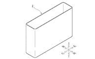
本実施形態は、図1に示す大型の非水電解質二次電池1及びその製造方法について説明する。この非水電解質二次電池1は、前後方向の幅が狭い角形の電池であり、組電池に用いるものである。 This embodiment demonstrates the large sized nonaqueous electrolyte secondary battery 1 shown in FIG. 1, and its manufacturing method. This nonaqueous electrolyte secondary battery 1 is a rectangular battery having a narrow width in the front-rear direction, and is used for an assembled battery.
上記非水電解質二次電池1は、図2に示すような方形容器状の金属ケース2の内部に、図示しない発電要素を収納し非水電解液を満たして、この金属ケース2の上端開口部を図1に示した蓋板3で塞いだものである。金属ケース2は、アルミニウム合金やステンレス鋼等の金属板からなり、上下や左右方向に比べ前後の幅が狭い方形容器状をなしている。蓋板3は、金属ケース2と同様の金属板であり、左右方向に細長い方形をなしている。この蓋板3は、金属ケース2の上端開口部に嵌まり込み、周囲を溶接等で塞ぐことにより内部を密閉している。また、この蓋板3の左右の端部からは、金属ケース2の内部で発電要素の電極に接続された正負の端子4、4が封止されて突出している。発電要素は、正負の電極をセパレータを介して長円筒形に巻回した巻回型のものが用いられる。
The non-aqueous electrolyte secondary battery 1 includes a rectangular container-shaped
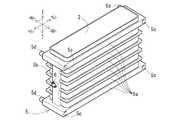
上記金属ケース2には、図3に示すように、この金属ケース2の外表面上で直接射出成形することにより樹脂フレーム5が樹脂成形されて金属ケース2の外表面に固着されている。金属ケース2の外表面上での樹脂成形とは、金属ケース2の外表面を樹脂成形用の金型で囲むことにより、この金属ケース2の外表面を金型の一部として利用した樹脂成形法をいう。また、この樹脂成形の際には、温度センサ6を金型の内側に突入させるように配置することにより、樹脂フレーム5の内部にこの温度センサ6の先端部が埋め込まれるようにしている。さらに、この金属ケース2は、予め外表面に微細な凹凸面が形成される表面処理を施すことにより、樹脂フレーム5が射出成形によって強固に固着されるようにしている。ただし、この樹脂フレーム5は、金属ケース2の外表面の全面を覆うように固着されるのではなく、この外表面における前後と左右方向を向く外側面の一部だけに固着して、金属ケース2の外表面からの放熱を阻害しないようにしている。
As shown in FIG. 3, the
上記樹脂フレーム5は、金属ケース2における四方の外側面の周囲を全周にわたって水平方向に取り囲むような細い桟部5aを上下に複数本間隔をあけて配置している。また、これら上下に配置された複数本の桟部5aは、左右方向を向く外側面の前後方向の中央部に上下にわたって配置された柱部5bを介して一体的に繋がっている。さらに、この樹脂フレーム5の上下の端の桟部5a、5aは、上下方向に少し太く形成されると共に、左右方向に少し突出するように形成され、この左右方向の突出部分における前方を向く面に係合穴5cをそれぞれ穿設すると共に、後方を向く面からは係合突起5dをそれぞれ突設している。従って、金属ケース2の外表面は、外側面については、複数本の桟部5aの間等のこれら桟部5aや柱部5bが固着していない部分が金属露出面として露出し、外底面については全面が金属露出面として露出することになる。
The
上記温度センサ6は、樹脂フレーム5における左側の柱部5bに先端部が埋め込まれている。この温度センサ6は、図4に示すように、鍔のある円筒形の先端にサーミスタの温度検知部6aが配置されたものであり、この温度検知部6aは、金属ケース2の左方向を向く外側面に当接した状態で埋め込まれている。また、この温度センサ6の端子は、樹脂フレーム5に埋め込まれていない基部の背面から突出している。
The
図3に示した樹脂フレーム5を固着した金属ケース2は、必要に応じて上端開口部を塞いで、電着塗装を行うことにより、外表面における樹脂フレーム5の桟部5aや柱部5bが固着していない部分であって、温度センサ6の温度検知部6aも当接していない部分である金属露出面が絶縁塗装膜によって覆われる。電着塗装は、電着槽内に水溶性塗料を溶かして金属ケース2を浸け、カチオンタイプの塗料の場合には金属ケース2を負極にし対極を正極として高電圧を印加することにより、金属ケース2の外表面における金属面が露出した金属露出面にのみ選択的に絶縁塗装膜を形成する塗装方法である。そして、このようにして金属露出面に形成した絶縁塗装膜は、乾燥と焼き付け処理を行うことにより、絶縁性と耐食性を備えると共に耐熱性や耐候性を備えた劣化し難い強い塗膜となる。
The
上記のようにして樹脂フレーム5を固着して絶縁塗装膜を形成した金属ケース2は、内部に発電要素を収納して、上端開口部を蓋板3で塞ぐことにより、図1に示した非水電解質二次電池1が完成する。非水電解液は、通常は、金属ケース2の上端開口部を蓋板3で塞いだ後に、金属ケース2又は蓋板3に設けられた注液口から注入され、この注入が完了すると注液口が封口される。
The
上記非水電解質二次電池1は、図5に示すように、複数個を、樹脂フレーム5の前方と後方を向く面を重ね合わせると共に、一方の係合穴5cに他方の係合突起5dを嵌入させて、前後方向に隣接させて並べることにより組電池とすることができる。この組電池は、そのまま適宜な組電池ケースに収納してもよいし、全体を止め付け具等で止め付けて一体化させてもよい。また、非水電解質二次電池1の端子4間は、端子接続具を使って適宜接続すればよい。このような組電池においても、隣接する非水電解質二次電池1の樹脂フレーム5の桟部5a同士が当接して、上下の桟部5a、5aの間にスリット状の隙間が設けられるので、ここに冷却風を流すことにより各非水電解質二次電池1の冷却を効率良く行うことができる。また、各非水電解質二次電池1の温度センサ6は、端子を図示しない外部の検出機器や制御機器等に接続することにより、これらの非水電解質二次電池1の電池温度を検出することができる。
As shown in FIG. 5, the non-aqueous electrolyte secondary battery 1 has a plurality of
上記構成の非水電解質二次電池1は、金属ケース2と一体化した樹脂フレーム5に温度センサ6が埋め込まれるので、この非水電解質二次電池1の電池温度を正確に検出することができる位置にこの温度センサ6を配置することができる。本実施形態では、樹脂フレーム5の柱部5bを利用して、金属ケース2の左側の外側面の中央部に温度検知部6aが当接するように温度センサ6が配置されている。しかも、この温度センサ6は、絶縁塗装膜を介することなく金属ケース2の外側面に温度検知部6aを当接させているので、この外側面の温度を直接正確に検出することができる。さらに、この温度センサ6の温度検知部6aは、樹脂フレーム5の柱部5bに覆われているので、非水電解質二次電池1に冷却風を当てた場合にも、この冷却風の影響を受けることなく、正確に金属ケース2の外側面の温度を検出することができる。
In the non-aqueous electrolyte secondary battery 1 having the above configuration, the
なお、上記実施形態では、温度センサ6の一部(先端部)を樹脂フレーム5の柱部5bに埋め込む場合を示したが、温度センサ6の全部を柱部5bに埋め込むようにすることもできる。例えば、温度センサ6をサーミスタに代えて熱電対を用いたものにすれば、この温度センサ6のさらなる小型化が可能になるので、柱部5bへの埋め込みも容易となる。
In the above-described embodiment, a case where a part (tip portion) of the
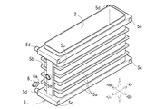
また、上記実施形態では、温度センサ6を樹脂フレーム5の柱部5bに埋め込む場合を示したが、この柱部5bには、図6に示すように、樹脂フレーム5の樹脂成形時に、金属ケース2の外側面に通じる穴状のセンサ取付部5eを形成しておき、例えば非水電解質二次電池1の完成後に、このセンサ取付部5eに温度センサ6の先端部を挿入して取り付けるようにしてもよい。この場合も、温度センサ6は、温度検知部6aが金属ケース2の外側面に当接するように取り付けられる。ただし、このセンサ取付部5eの穴は、電着塗装による絶縁塗装膜の形成時には塞いでおく。ところで、樹脂フレーム5の樹脂成形後に、機械加工等によって金属ケース2の外側面に達するような穴を形成して、これをセンサ取付部5eとするのは、金属ケース2と樹脂フレーム5との固着が強固であるため、現実には困難である。
In the above embodiment, the
また、上記実施形態では、温度センサ6を樹脂フレーム5の柱部5bに埋め込む場合を示したが、温度センサ6を埋め込む位置やセンサ取付部5eを形成する位置は任意であり、例えば図7に示すように、上下方向の中段の桟部5aの左右方向の中央部に埋め込むこともできる。このような非水電解質二次電池1を図5に示したような組電池にすると、隣接する非水電解質二次電池1の樹脂フレーム5の桟部5aの前後方向の面同士が当接するので、この温度センサ6は、少なくとも前後方向に突出しないように、桟部5aの内部に完全に埋め込むことが好ましい。しかも、この温度センサ6の端子は、桟部5aの上下の面から突出させる必要があり、このようにして突出させた端子に配線を接続した場合、この配線は、上下の桟部5a、5aの間の狭いスリット状の隙間を通して左右方向に引き出すことになるので、この隙間を流れる冷却風を遮るおそれが生じる。そこで、図7に示した温度センサ6は、樹脂フレーム5の樹脂成形の際に、配線6bも桟部5aの内部に埋め込んで柱部5bから外部に引き出すようにして、この配線6bが冷却風の通気路を遮ることがないようにしている。
Moreover, in the said embodiment, although the case where the
上記のように樹脂フレーム5の桟部5aに温度センサ6を埋め込むと、金属ケース2において最も温度が高くなる外表面である、最も面積の広い前後方向を向く外側面の中央部に温度センサ6が配置されるので、非水電解質二次電池1の電池温度をさらに正確に検出することができる。しかも、このように冷却風の通気路中に温度センサ6を配置した場合であっても、上記実施形態と同様に、温度センサ6の温度検知部6aが樹脂フレーム5の桟部5aに覆われているので、この冷却風の影響を受けることなく正確に金属ケース2の外側面の温度を検出することができる。
When the
また、温度センサ6は、非水電解質二次電池1の電池温度を正確に検出することができる位置であれば、金属ケース2の外表面のいずれの位置に温度検知部6aを当接させてもよい。さらに、温度センサ6を樹脂フレーム5に埋め込む場合には、この樹脂フレーム5を樹脂成形する際に大きな圧力をかけて樹脂を注入するので、実際には、温度検知部6aと金属ケース2の外表面との間に樹脂が入り込んで1mm程度の薄い樹脂層が形成されることがある。このため、上記実施形態では、温度センサ6の温度検知部6aを金属ケース2の外表面に当接させる場合を示したが、温度センサ6を樹脂フレーム5に埋め込むときには、温度検知部6aが金属ケース2の外表面に近接する場合であってもよい。そして、ここでいう近接とは、このように樹脂成形の際に温度検知部6aと金属ケース2の外表面との間に入り込んだ薄い樹脂層のみを介して接近していることをいう。
In addition, the
また、上記実施形態では、非水電解質二次電池1の電池温度を検出する温度センサ6を用いる場合について説明したが、この温度センサ6に代えて、又は、この温度センサ6と共に、例えば非水電解質二次電池1の内圧の上昇によって膨れた金属ケース2の膨れを検出する膨れセンサ(歪みセンサ)等を用いることもでき、センサの種類は必ずしも温度センサには限定されない。
In the above embodiment, the case where the
また、上記実施形態では、射出成形によって金属ケース2の外表面上で樹脂フレーム5を樹脂成形する場合を示したが、金属ケース2の外表面を利用した金型で樹脂成形が可能であれば、必ずしも射出成形によるものには限定されない。
Moreover, in the said embodiment, although the case where the
また、上記実施形態では、金属ケース2の外表面に微細な凹凸面が形成される表面処理を予め施す場合を示したが、樹脂成形によって樹脂フレーム5が金属ケース2の外表面に確実に固着されるのであれば、このような表面処理は必ずしも必要ない。さらに、金属ケース2の外表面に表面処理を行う場合であっても、樹脂フレーム5が確実に固着されるためのものであれば、微細な凹凸面が形成されるのとは異なる表面処理であってもよい。さらに、この表面処理は、金属ケース2の外表面における樹脂フレーム5が固着する部分だけ、又は、その周辺も含めた部分だけに施すようにしてもよく、逆に、金属ケース2の外表面だけでなく、処理の都合等により、金属ケース2の内表面に施してもよい。
Moreover, although the case where the surface treatment in which a fine uneven surface is formed on the outer surface of the
また、上記実施形態では、桟部5aと柱部5bからなる樹脂フレーム5について説明したが、金属ケース2の外表面の一部に固着されるのであれば、この樹脂フレーム5の構成は任意である。さらに、この樹脂フレーム5は、全ての部分が繋がっている必要はなく、複数のピンポイント状や島状の部分があってもよい。
Moreover, in the said embodiment, although the
また、上記実施形態では、電着塗装によって絶縁塗装膜が形成される場合を示したが、金属ケース2の金属露出面を絶縁や防食するためのものであれば、他の塗装法による塗装をしてもよく、粘着テープ等を貼り付けてもよい。さらに、特に絶縁や防食が不要であれば、必ずしもこのような塗装を行ったり粘着テープ等を貼り付ける必要はない。
Moreover, in the said embodiment, although the case where the insulating coating film was formed by electrodeposition coating was shown, as long as it is for insulating and corrosion-proofing the metal exposed surface of the
また、上記実施形態では、蓋板3が金属ケース2と同様の金属板からなる場合を示したが、この蓋板3の材質は任意であり、必ずしも正負の端子4、4が突出する蓋板3には限定されない。さらに、上記実施形態では、方形容器状の金属ケース2を用いる場合を示したが、金属ケース2の形状は任意であり、この金属ケース2自身が端子を構成したり、この金属ケース2から端子が突出するようになっていてもよい。さらに、電池外装ケースは、金属ケース2と蓋板3によって構成されるものには限定されず、金属ケース2に蓋板3以外のものを組み合わせたものでもよく、単一の部品又は複数の部品からなる金属ケースのみによって電池外装ケースが構成されるようになっていてもよい。
Moreover, although the case where the cover plate 3 was made of the same metal plate as the
また、上記実施形態では、発電要素が長円筒形に巻回された巻回型のものである場合を示したが、発電要素の形状は任意であり、通常の円筒形のものであってもよく、巻回型以外の積層型等の発電要素であってもよい。 Moreover, although the case where the power generation element is a wound type wound in a long cylindrical shape is shown in the above embodiment, the shape of the power generation element is arbitrary, and even if it is a normal cylindrical shape Alternatively, a power generation element such as a laminated type other than the wound type may be used.
また、上記実施形態では、組電池に用いる非水電解質二次電池1について説明したが、単独で使用する非水電解質二次電池1であっても同様に実施可能である。このような非水電解質二次電池1は、例えば電池収納スペース等に隙間なく収納した場合であっても、別部品の枠体やスペーサ等を用いることなく、電池収納スペース等との間に、樹脂フレーム5が介在して桟部5a、5aの間のスリット状の隙間を設けることができるので、ここに冷却風を流すことにより非水電解質二次電池1の冷却を効率良く行うことができる。
Moreover, in the said embodiment, although the nonaqueous electrolyte secondary battery 1 used for an assembled battery was demonstrated, even if it is the nonaqueous electrolyte secondary battery 1 used independently, it can implement similarly. Even if such a nonaqueous electrolyte secondary battery 1 is stored in a battery storage space or the like without a gap, for example, between the battery storage space and the like without using a separate frame or spacer, Since the
また、上記実施形態では、非水電解質二次電池1について説明したが、これに限らず蓄積した電気を放電できる蓄電装置であればよいので、一次電池や二次電池、燃料電池等の化学電池の他に、電気二重層キャパシタ等であってもよい。 Moreover, in the said embodiment, although the nonaqueous electrolyte secondary battery 1 was demonstrated, since it is not restricted to this, what is necessary is just the electrical storage apparatus which can discharge the accumulate | stored electricity, Therefore Chemical batteries, such as a primary battery, a secondary battery, and a fuel cell In addition, an electric double layer capacitor or the like may be used.
1 非水電解質二次電池
2 金属ケース
3 蓋板
4 端子
5 樹脂フレーム
5a 桟部
5b 柱部
5c 係合穴
5d 係合突起
5e センサ取付部
6 温度センサ
6a 温度検知部
6b 配線
DESCRIPTION OF SYMBOLS 1 Nonaqueous electrolyte
Claims (8)
前記金属ケースの外表面で樹脂成形することにより、前記金属ケースの外表面の一部に固着された樹脂フレームと、
前記金属ケースの外表面に温度センサの検知部が当接又は近接する状態で前記樹脂フレームに埋め込まれた温度センサと、
を備え、
前記金属ケースは、前記樹脂フレームが固着されていない金属露出面を外側面に有することを特徴とする蓄電装置。 In a power storage device using a metal case,
By resin molding on the outer surface of the metal case, a resin frame fixed to a part of the outer surface of the metal case;
A temperature sensor embedded in the resin frame in a state where the detection part of the temperature sensor is in contact with or close to the outer surface of the metal case;
With
The power storage device, wherein the metal case has a metal exposed surface to which the resin frame is not fixed on an outer surface.
前記金属ケースの外表面上で樹脂成形することにより、この金属ケースの外表面の一部に固着されると共に、この樹脂成形の際に温度センサの検知部を金属ケースの外表面に当接又は近接させた状態で内部にこの温度センサの全部又は一部が埋め込まれた樹脂フレームを備え、
前記金属ケースは、前記樹脂フレームが固着されていない金属露出面を外側面に有することを特徴とする蓄電装置。 In a power storage device using a metal case,
By resin molding on the outer surface of the metal case, the metal case is fixed to a part of the outer surface of the metal case, and the detection part of the temperature sensor is brought into contact with the outer surface of the metal case during the resin molding. With a resin frame in which all or part of this temperature sensor is embedded inside,
The power storage device, wherein the metal case has a metal exposed surface to which the resin frame is not fixed on an outer surface.
前記金属ケースの外表面上で樹脂成形することにより、この金属ケースの外表面の一部に固着されると共に、この樹脂成形の際に金属ケースの外表面に通じる温度センサ取付部が形成された樹脂フレームを備え、
前記金属ケースは、前記樹脂フレームが固着されていない金属露出面を外側面に有することを特徴とする蓄電装置。 In a power storage device using a metal case,
By resin molding on the outer surface of the metal case, a temperature sensor mounting portion is formed which is fixed to a part of the outer surface of the metal case and communicates with the outer surface of the metal case during the resin molding. With resin frame,
The power storage device, wherein the metal case has a metal exposed surface to which the resin frame is not fixed on an outer surface.
前記金属ケースの外表面に温度センサの検知部を当接させた状態で、この金属ケースの外表面上で樹脂成形することにより、この金属ケースの外表面の一部に固着されることにより、前記金属ケースの外側面に樹脂フレームの固着されていない金属露出面を形成すると共に、内部にこの温度センサの全部又は一部を埋め込んだ樹脂フレームを形成することを特徴とする蓄電装置の製造方法。 In a method for manufacturing a power storage device using a metal case,
In a state where the detection part of the temperature sensor is in contact with the outer surface of the metal case, by being resin-molded on the outer surface of the metal case, by being fixed to a part of the outer surface of the metal case, A method for manufacturing a power storage device, comprising forming a metal exposed surface to which a resin frame is not fixed to an outer surface of the metal case, and forming a resin frame in which all or part of the temperature sensor is embedded. .
8. The power storage device according to claim 1, wherein the resin frame includes a plurality of crosspieces and a pillar that connects the plurality of crosspieces.
Priority Applications (1)
| Application Number | Priority Date | Filing Date | Title |
|---|---|---|---|
| JP2008278362A JP5589275B2 (en) | 2008-10-29 | 2008-10-29 | Power storage device and manufacturing method thereof |
Applications Claiming Priority (1)
| Application Number | Priority Date | Filing Date | Title |
|---|---|---|---|
| JP2008278362A JP5589275B2 (en) | 2008-10-29 | 2008-10-29 | Power storage device and manufacturing method thereof |
Publications (3)
| Publication Number | Publication Date |
|---|---|
| JP2010108699A JP2010108699A (en) | 2010-05-13 |
| JP2010108699A5 JP2010108699A5 (en) | 2011-12-08 |
| JP5589275B2 true JP5589275B2 (en) | 2014-09-17 |
Family
ID=42297957
Family Applications (1)
| Application Number | Title | Priority Date | Filing Date |
|---|---|---|---|
| JP2008278362A Active JP5589275B2 (en) | 2008-10-29 | 2008-10-29 | Power storage device and manufacturing method thereof |
Country Status (1)
| Country | Link |
|---|---|
| JP (1) | JP5589275B2 (en) |
Cited By (1)
| Publication number | Priority date | Publication date | Assignee | Title |
|---|---|---|---|---|
| KR101800815B1 (en) | 2014-11-03 | 2017-11-23 | 주식회사 엘지화학 | Battery module with insert injection mold structure of cell |
Families Citing this family (6)
| Publication number | Priority date | Publication date | Assignee | Title |
|---|---|---|---|---|
| CN106206007A (en) * | 2016-09-14 | 2016-12-07 | 铜陵源丰电子有限责任公司 | A kind of large scale industry electricity container of automatic on/off electricity |
| CN106206005B (en) * | 2016-09-14 | 2019-01-01 | 铜陵源丰电子有限责任公司 | A kind of intelligent water-cooled motor-driven heat dissipation capacitor |
| CN106373777A (en) * | 2016-09-14 | 2017-02-01 | 铜陵源丰电子有限责任公司 | Heat-exchanging anti-explosion capacitor |
| CN106373778B (en) * | 2016-09-14 | 2019-01-01 | 铜陵源丰电子有限责任公司 | A kind of noinductive capacitor |
| KR20210027948A (en) * | 2019-09-03 | 2021-03-11 | 주식회사 엘지화학 | Battery Pack, Battery Rack And Energy Storage System Comprising The Same |
| SE2250626A1 (en) * | 2022-05-25 | 2023-11-26 | Northvolt Ab | Integrated sensor in a battery module |
Family Cites Families (13)
| Publication number | Priority date | Publication date | Assignee | Title |
|---|---|---|---|---|
| JPS6332874A (en) * | 1986-07-24 | 1988-02-12 | Matsushita Electric Works Ltd | Temperature sensor fitting structure for storage battery |
| JPH0461762A (en) * | 1990-06-27 | 1992-02-27 | Matsushita Electric Works Ltd | Storage battery device |
| JPH065267A (en) * | 1992-06-17 | 1994-01-14 | Matsushita Electric Ind Co Ltd | Manufacture of square-shaped battery |
| JP2001035450A (en) * | 1999-07-19 | 2001-02-09 | Toyota Motor Corp | Rectangular battery |
| JP3068733U (en) * | 1999-11-04 | 2000-05-16 | 宇呂電子工業株式会社 | Battery box |
| JP2002334684A (en) * | 2001-05-02 | 2002-11-22 | Daiwa Kasei Ind Co Ltd | Battery case |
| JP3778841B2 (en) * | 2001-10-26 | 2006-05-24 | 三洋電機株式会社 | Battery pack manufacturing method |
| JP2003346747A (en) * | 2002-05-28 | 2003-12-05 | Sanyo Electric Co Ltd | Battery pack and manufacturing method of the same |
| JP4530784B2 (en) * | 2004-09-30 | 2010-08-25 | 三洋電機株式会社 | Pack battery |
| EP1875582B1 (en) * | 2005-03-16 | 2017-02-22 | Ford Global Technologies, LLC | Power supply system comprising temperature sensor stations |
| JP4958409B2 (en) * | 2005-06-01 | 2012-06-20 | 三洋電機株式会社 | Assembled battery |
| JP4640622B2 (en) * | 2008-04-25 | 2011-03-02 | 本田技研工業株式会社 | Power storage device and metal battery case manufacturing method |
| JP5332490B2 (en) * | 2008-10-17 | 2013-11-06 | 株式会社Gsユアサ | Power storage device and manufacturing method thereof |
-
2008
- 2008-10-29 JP JP2008278362A patent/JP5589275B2/en active Active
Cited By (1)
| Publication number | Priority date | Publication date | Assignee | Title |
|---|---|---|---|---|
| KR101800815B1 (en) | 2014-11-03 | 2017-11-23 | 주식회사 엘지화학 | Battery module with insert injection mold structure of cell |
Also Published As
| Publication number | Publication date |
|---|---|
| JP2010108699A (en) | 2010-05-13 |
Similar Documents
| Publication | Publication Date | Title |
|---|---|---|
| JP5589275B2 (en) | Power storage device and manufacturing method thereof | |
| JP2010108699A5 (en) | ||
| JP5266759B2 (en) | Lead acid battery | |
| KR101267652B1 (en) | Pressurizing apparatus of laminate type battery | |
| KR101303477B1 (en) | Battery assembly | |
| JP4640622B2 (en) | Power storage device and metal battery case manufacturing method | |
| JP2008140711A (en) | Battery pack | |
| JP6449315B2 (en) | Battery pack | |
| JP2010257686A (en) | Liquid leakage propagation restraining structure for electricity storage device and bus bar module | |
| KR101688569B1 (en) | Battery Cell Having Step-formed Structure and Method for Checking Insulation Resistance Defects Thereof | |
| JP4530711B2 (en) | Pack battery | |
| CN107104211B (en) | Power storage device and method for manufacturing power storage device | |
| KR20120006984A (en) | Galvanic cell having a frame and method for the production of said galvanic cell | |
| WO2000013241A1 (en) | Method and structure for connecting batteries | |
| JP5332490B2 (en) | Power storage device and manufacturing method thereof | |
| JP5623920B2 (en) | Double molded product, method for manufacturing double molded product, and battery module | |
| JP5691778B2 (en) | Nonaqueous electrolyte secondary battery | |
| JP2002367652A (en) | Fuel cell housing case | |
| JP3454738B2 (en) | Battery pack with built-in protection element | |
| JP6780261B2 (en) | Power storage device | |
| JP2010097865A5 (en) | ||
| JP6715927B2 (en) | Battery module | |
| JP2008016190A (en) | Battery pack | |
| JP5329201B2 (en) | Pack battery | |
| JP6135343B2 (en) | Wiring module and power storage module |
Legal Events
| Date | Code | Title | Description |
|---|---|---|---|
| A711 | Notification of change in applicant |
Free format text: JAPANESE INTERMEDIATE CODE: A712 Effective date: 20100507 |
|
| A521 | Request for written amendment filed |
Free format text: JAPANESE INTERMEDIATE CODE: A523 Effective date: 20111019 |
|
| A621 | Written request for application examination |
Free format text: JAPANESE INTERMEDIATE CODE: A621 Effective date: 20111019 |
|
| A977 | Report on retrieval |
Free format text: JAPANESE INTERMEDIATE CODE: A971007 Effective date: 20130524 |
|
| A131 | Notification of reasons for refusal |
Free format text: JAPANESE INTERMEDIATE CODE: A131 Effective date: 20130604 |
|
| A521 | Request for written amendment filed |
Free format text: JAPANESE INTERMEDIATE CODE: A523 Effective date: 20130730 |
|
| A131 | Notification of reasons for refusal |
Free format text: JAPANESE INTERMEDIATE CODE: A131 Effective date: 20130903 |
|
| A521 | Request for written amendment filed |
Free format text: JAPANESE INTERMEDIATE CODE: A523 Effective date: 20131030 |
|
| A131 | Notification of reasons for refusal |
Free format text: JAPANESE INTERMEDIATE CODE: A131 Effective date: 20140107 |
|
| A131 | Notification of reasons for refusal |
Free format text: JAPANESE INTERMEDIATE CODE: A131 Effective date: 20140325 |
|
| A521 | Request for written amendment filed |
Free format text: JAPANESE INTERMEDIATE CODE: A523 Effective date: 20140402 |
|
| A131 | Notification of reasons for refusal |
Free format text: JAPANESE INTERMEDIATE CODE: A131 Effective date: 20140603 |
|
| A521 | Request for written amendment filed |
Free format text: JAPANESE INTERMEDIATE CODE: A523 Effective date: 20140606 |
|
| TRDD | Decision of grant or rejection written | ||
| A01 | Written decision to grant a patent or to grant a registration (utility model) |
Free format text: JAPANESE INTERMEDIATE CODE: A01 Effective date: 20140701 |
|
| A61 | First payment of annual fees (during grant procedure) |
Free format text: JAPANESE INTERMEDIATE CODE: A61 Effective date: 20140714 |
|
| R150 | Certificate of patent or registration of utility model |
Ref document number: 5589275 Country of ref document: JP Free format text: JAPANESE INTERMEDIATE CODE: R150 |