JP5586521B2 - Method and apparatus for identifying knocking of an internal combustion engine with at least one cylinder - Google Patents
Method and apparatus for identifying knocking of an internal combustion engine with at least one cylinder Download PDFInfo
- Publication number
- JP5586521B2 JP5586521B2 JP2011096360A JP2011096360A JP5586521B2 JP 5586521 B2 JP5586521 B2 JP 5586521B2 JP 2011096360 A JP2011096360 A JP 2011096360A JP 2011096360 A JP2011096360 A JP 2011096360A JP 5586521 B2 JP5586521 B2 JP 5586521B2
- Authority
- JP
- Japan
- Prior art keywords
- knocking
- cylinder
- signal
- frequency
- bandpass filter
- Prior art date
- Legal status (The legal status is an assumption and is not a legal conclusion. Google has not performed a legal analysis and makes no representation as to the accuracy of the status listed.)
- Expired - Fee Related
Links
Images


Classifications
-
- F—MECHANICAL ENGINEERING; LIGHTING; HEATING; WEAPONS; BLASTING
- F02—COMBUSTION ENGINES; HOT-GAS OR COMBUSTION-PRODUCT ENGINE PLANTS
- F02P—IGNITION, OTHER THAN COMPRESSION IGNITION, FOR INTERNAL-COMBUSTION ENGINES; TESTING OF IGNITION TIMING IN COMPRESSION-IGNITION ENGINES
- F02P5/00—Advancing or retarding ignition; Control therefor
- F02P5/04—Advancing or retarding ignition; Control therefor automatically, as a function of the working conditions of the engine or vehicle or of the atmospheric conditions
- F02P5/145—Advancing or retarding ignition; Control therefor automatically, as a function of the working conditions of the engine or vehicle or of the atmospheric conditions using electrical means
- F02P5/15—Digital data processing
- F02P5/152—Digital data processing dependent on pinking
-
- G—PHYSICS
- G01—MEASURING; TESTING
- G01L—MEASURING FORCE, STRESS, TORQUE, WORK, MECHANICAL POWER, MECHANICAL EFFICIENCY, OR FLUID PRESSURE
- G01L23/00—Devices or apparatus for measuring or indicating or recording rapid changes, such as oscillations, in the pressure of steam, gas, or liquid; Indicators for determining work or energy of steam, internal-combustion, or other fluid-pressure engines from the condition of the working fluid
- G01L23/22—Devices or apparatus for measuring or indicating or recording rapid changes, such as oscillations, in the pressure of steam, gas, or liquid; Indicators for determining work or energy of steam, internal-combustion, or other fluid-pressure engines from the condition of the working fluid for detecting or indicating knocks in internal-combustion engines; Units comprising pressure-sensitive members combined with ignitors for firing internal-combustion engines
-
- F—MECHANICAL ENGINEERING; LIGHTING; HEATING; WEAPONS; BLASTING
- F02—COMBUSTION ENGINES; HOT-GAS OR COMBUSTION-PRODUCT ENGINE PLANTS
- F02P—IGNITION, OTHER THAN COMPRESSION IGNITION, FOR INTERNAL-COMBUSTION ENGINES; TESTING OF IGNITION TIMING IN COMPRESSION-IGNITION ENGINES
- F02P5/00—Advancing or retarding ignition; Control therefor
- F02P5/04—Advancing or retarding ignition; Control therefor automatically, as a function of the working conditions of the engine or vehicle or of the atmospheric conditions
- F02P5/145—Advancing or retarding ignition; Control therefor automatically, as a function of the working conditions of the engine or vehicle or of the atmospheric conditions using electrical means
- F02P5/15—Digital data processing
- F02P5/152—Digital data processing dependent on pinking
- F02P5/1522—Digital data processing dependent on pinking with particular means concerning an individual cylinder
-
- G—PHYSICS
- G01—MEASURING; TESTING
- G01L—MEASURING FORCE, STRESS, TORQUE, WORK, MECHANICAL POWER, MECHANICAL EFFICIENCY, OR FLUID PRESSURE
- G01L23/00—Devices or apparatus for measuring or indicating or recording rapid changes, such as oscillations, in the pressure of steam, gas, or liquid; Indicators for determining work or energy of steam, internal-combustion, or other fluid-pressure engines from the condition of the working fluid
- G01L23/22—Devices or apparatus for measuring or indicating or recording rapid changes, such as oscillations, in the pressure of steam, gas, or liquid; Indicators for determining work or energy of steam, internal-combustion, or other fluid-pressure engines from the condition of the working fluid for detecting or indicating knocks in internal-combustion engines; Units comprising pressure-sensitive members combined with ignitors for firing internal-combustion engines
- G01L23/221—Devices or apparatus for measuring or indicating or recording rapid changes, such as oscillations, in the pressure of steam, gas, or liquid; Indicators for determining work or energy of steam, internal-combustion, or other fluid-pressure engines from the condition of the working fluid for detecting or indicating knocks in internal-combustion engines; Units comprising pressure-sensitive members combined with ignitors for firing internal-combustion engines for detecting or indicating knocks in internal combustion engines
- G01L23/225—Devices or apparatus for measuring or indicating or recording rapid changes, such as oscillations, in the pressure of steam, gas, or liquid; Indicators for determining work or energy of steam, internal-combustion, or other fluid-pressure engines from the condition of the working fluid for detecting or indicating knocks in internal-combustion engines; Units comprising pressure-sensitive members combined with ignitors for firing internal-combustion engines for detecting or indicating knocks in internal combustion engines circuit arrangements therefor
-
- Y—GENERAL TAGGING OF NEW TECHNOLOGICAL DEVELOPMENTS; GENERAL TAGGING OF CROSS-SECTIONAL TECHNOLOGIES SPANNING OVER SEVERAL SECTIONS OF THE IPC; TECHNICAL SUBJECTS COVERED BY FORMER USPC CROSS-REFERENCE ART COLLECTIONS [XRACs] AND DIGESTS
- Y02—TECHNOLOGIES OR APPLICATIONS FOR MITIGATION OR ADAPTATION AGAINST CLIMATE CHANGE
- Y02T—CLIMATE CHANGE MITIGATION TECHNOLOGIES RELATED TO TRANSPORTATION
- Y02T10/00—Road transport of goods or passengers
- Y02T10/10—Internal combustion engine [ICE] based vehicles
- Y02T10/40—Engine management systems
Landscapes
- Engineering & Computer Science (AREA)
- Chemical & Material Sciences (AREA)
- Combustion & Propulsion (AREA)
- Signal Processing (AREA)
- Mechanical Engineering (AREA)
- General Engineering & Computer Science (AREA)
- Physics & Mathematics (AREA)
- General Physics & Mathematics (AREA)
- Combined Controls Of Internal Combustion Engines (AREA)
Description
本発明は、少なくとも1つのシリンダを備えた内燃機関のノッキングを識別する方法と装置に関する。 The present invention relates to a method and apparatus for identifying knocking of an internal combustion engine with at least one cylinder.
ノッキング調節装置を備えた内燃機関においてノッキングを識別する方法が実施されることが公知であり、この方法では1つまたは複数のノッキングセンサによって受信されて、電気信号に変換される個体伝播音が信号処理装置において処理される。例えば内燃機関の制御装置内に設けられている信号処理装置はディジタルまたはアナログ信号処理を行う。信号処理ないし所属の評価回路の重要な構成要素はバンドパスフィルタである。バンドパスフィルタの特性すなわち中間周波数、質などは、ノッキング周波数のエネルギ論的な重点が通過帯域内にあり、一方ノイズの周波数は可能な限り通過帯域外にあるように設計される。これによってノイズが実質的に抑制される。 It is known to implement a method for identifying knocking in an internal combustion engine equipped with a knocking control device, in which an individual propagation sound received by one or more knocking sensors and converted into an electrical signal is a signal. It is processed in the processing device. For example, a signal processing device provided in a control device for an internal combustion engine performs digital or analog signal processing. An important component of signal processing or the associated evaluation circuit is a bandpass filter. The characteristics of the bandpass filter, i.e. intermediate frequency, quality, etc., are designed so that the energetic emphasis of the knocking frequency is in the passband, while the noise frequency is as far as possible out of the passband. This substantially suppresses noise.
複数のサブユニット及びアクチュエータを備える現代のエンジンないし内燃機関では、ノイズの周波数は場合によっては回転数に大きく依存する。したがって、回転数帯の全体にわたり良好なノッキング識別を保障できるようにするために、このようなエンジンないし内燃機関では、回転数に依存するフィルタ特性を用いて処理が行われる。上述のノッキング識別を行う装置は刊行物EP 0 576 650 B1に記載されている。
In modern engines or internal combustion engines with a plurality of subunits and actuators, the frequency of the noise depends in some cases on the rotational speed. Therefore, in order to ensure good knocking identification over the entire rotation speed range, in such an engine or internal combustion engine, processing is performed using a filter characteristic that depends on the rotation speed. An apparatus for performing the above-described knocking identification is described in the
EP 0 576 650から公知のノッキング識別装置は、信号処理経路にバンドパスフィルタを包含し、このバンドパスフィルタの中間周波数はエンジン回転数に依存して可変である。中間周波数は、ノッキングに起因する信号成分が可能な限り殆どフィルタリングされず、バックグラウンド信号及びノイズ信号は可能な限り大部分フィルタリング除去されるように設計される。周波数は回転数に依存してずらすことができるので、可変の中間周波数を有するバンドパスフィルタが使用される。ノッキングは公知の装置では通常の場合、ノッキングの典型的な信号成分から形成される積分値が、所定のようにしてバックグラウンド信号に依存する値と異なる場合に識別される。
The knocking identification device known from
フィルタ特性が変化することにより、燃焼のノイズの尺度を表すフィルタリングされた信号も変化する。目下の燃焼のノイズ、ないしいわゆるノッキング積分値ikrと、同一のシリンダにおける過去の複数の燃焼にわたり平均化されたノイズ、いわゆる基準レベルrkrとの比率virkrを形成することによりノッキングを識別するので、フィルタ特性が変わる際に問題が発生する可能性がある。virkr=ikr/rkr(old)の値がノッキング識別閾値keを上回る場合にノッキングが識別される。すなわちikr>rkr(old)*keの場合にノッキングが識別される。 As the filter characteristics change, the filtered signal representing a measure of combustion noise also changes. Since the noise of the current combustion, or so-called knocking integration value ikr, and the noise averaged over a plurality of past combustions in the same cylinder, the ratio of the so-called reference level rkr, virkr, is identified so that the filter Problems can occur when characteristics change. Knocking is identified when the value of virkr = ikr / rkr (old) exceeds the knocking identification threshold ke. That is, knocking is identified when ikr> rkr (old) * ke.
基準レベルの算出は通常の場合、ノッキングのない動作時に次式または類似の式によりに帰納的に行われる、また例えばDE−P195 456 49.1に記載されている。 The calculation of the reference level is usually done recursively according to the following or a similar equation during operation without knocking, and is described, for example, in DE-P195 456 49.1.
rkr(new)=(1-1/KRFTP)*rkr(old)+1/KRFTP*ikr
係数KRFTPはここではいわゆる追従係数と称される。
rkr (new) = (1-1 / KRFTP) * rkr (old) + 1 / KRFTP * ikr
The coefficient KRFTP is referred to herein as a so-called tracking coefficient.
ある燃焼から次の燃焼までにフィルタ特性が変化されると、すなわち、例えばフィルタの中間周波数が新たなないし変化した状況に適応されると、目下の燃焼ノイズないしノッキング積分値ikrは場合によっては顕著に変化するが、一方基準レベルrkrは緩慢にしか変化せず、ないし緩慢にしか追従されない。ikrの変化が例えば顕著な上昇である場合には、ノッキングがいわゆる誤識別される可能性がある。すなわち、ノッキングのない燃焼が誤ってノッキングのあるものとして識別される。したがって本来は必要の無い、点火角の変化が惹起される。この最初の誤識別の結果、さらなる誤識別が生じる可能性があり、何故ならば、ノッキングのある燃焼について測定されたノッキング積分値ikrは基準レベルrkrにおいては完全には考慮されず、ノッキングノイズと推定されてrkrが上昇することを回避するために係数keによって即座に除算されるからである。計算は次式により行われる。
rkr(new)=(1-1/KRFTP)*rkr(old)+1/KRFTP*(ikr/ke)
When the filter characteristics are changed from one combustion to the next, that is, for example, when the intermediate frequency of the filter is adapted to a new or changed situation, the current combustion noise or knocking integration value ikr may be noticeable in some cases. On the other hand, the reference level rkr changes only slowly and follows only slowly. If the change in ikr is, for example, a significant increase, knocking may be misidentified. That is, combustion without knocking is mistakenly identified as knocking. Therefore, a change in the ignition angle which is not necessary originally is caused. As a result of this initial misidentification, further misidentification can occur because the knocking integral value ikr measured for combustion with knocking is not fully considered at the reference level rkr, This is because it is immediately divided by the coefficient ke in order to avoid the estimated rkr rising. The calculation is performed by the following formula.
rkr (new) = (1-1 / KRFTP) * rkr (old) + 1 / KRFTP * (ikr / ke)
これとは反対に、燃焼ノイズが顕著に低減した場合のノッキング識別は所定の時間機能せず、すなわちノッキングのある燃焼が場合によっては識別されない。したがってフィルタ特性の変化は、ノッキング識別における時間的に制限された不確定要素となる。さらには、ノッキングの各々の誤識別は不必要に点火角度を後調整し、したがって出力及び効率の相応の損失に繋がる。他方ノッキングのある燃焼が識別されないことは、エンジンの磨耗を高めることになる。 In contrast, knocking identification when combustion noise is significantly reduced does not function for a predetermined time, i.e., combustion with knocking is not identified in some cases. The change in filter characteristics is therefore a time-limited uncertainty factor in knock identification. Furthermore, each misidentification of knocking unnecessarily postconditions the ignition angle, thus leading to a corresponding loss of power and efficiency. On the other hand, the failure to identify knocked combustion increases engine wear.
本発明の課題は、フィルタ特性の切換フェーズ中のノッキング識別における信頼性が向上した、少なくとも1つのシリンダを備えた内燃機関のノッキングを識別する方法および相応の装置を提供することである。 It is an object of the present invention to provide a method and corresponding device for identifying knocking of an internal combustion engine with at least one cylinder, with improved reliability in knocking identification during the switching phase of the filter characteristics.
方法に関する課題は、バンドパスフィルタの通過帯域の上側のコーナー周波数及び/又は下側のコーナー周波数をシリンダ固有に及び/又は回転数に依存して変化させることにより解決される。 The problem with the method is solved by changing the upper corner frequency and / or the lower corner frequency of the passband of the bandpass filter, depending on the cylinder and / or depending on the rotational speed.
装置に関する課題は、制御ユニットによって、バンドパスフィルタの通過帯域の上側のコーナー周波数及び/又は下側のコーナー周波数をシリンダ固有に及び/又は回転数に依存して変化させることにより解決される。 The problem with the device is solved by the control unit changing the upper corner frequency and / or the lower corner frequency of the passband of the bandpass filter, depending on the cylinder and / or depending on the rotational speed.
独立請求項記載の特徴を有する本発明による方法及び本発明による装置は、フィルタの切換フェーズの間でも、すなわちフィルタ特性が変化している間でもノッキングの誤識別が確実に回避されるという利点を有する。同時にノッキングはこのフェーズにおいても確実に識別される。この利点は、切換フェーズの間に修正されたノッキング識別方法が実施されることによって達成され、このノッキング識別方法ではノッキング識別閾値が比較的鈍感に切り換えられる、及び/又は、基準レベル追従が修正される。 The method according to the invention and the device according to the invention with the features of the independent claims have the advantage that knocking misidentification is reliably avoided even during the switching phase of the filter, i.e. while the filter characteristics are changing. Have. At the same time, knocking is reliably identified in this phase. This advantage is achieved by implementing a modified knock identification method during the switching phase, in which the knock identification threshold is switched to a relatively insensitive and / or reference level tracking is modified. The
本発明の別の利点は、従属請求項に記載された措置によって達成される。有利には切換フェーズに対して所定の継続時間がとられ、この継続時間の経過は例えばカウンタを用いて検出される。 Further advantages of the invention are achieved by the measures described in the dependent claims. A predetermined duration is preferably taken for the switching phase, and the passage of this duration is detected, for example, using a counter.
修正されたノッキング識別に必要である、ノッキング識別閾値及び/又は基準レベル追従に対する値は、有利には通常の値に与えられる適切な係数を用いて形成される。 The values for the knocking identification threshold and / or the reference level tracking required for the modified knocking identification are preferably formed using suitable factors given the normal values.
従属請求項に記載されている解決手段の別の利点は、ノッキングセンサの個々のシリンダへの異なる距離が考慮されることである。何故ならば、ノッキングセンサの個々のシリンダへの距離が異なることに基づいて、シリンダ内の燃焼に基づき発生する信号及び妨害信号の周波数がずれるからである。さらには、回転数が異なる場合には燃焼に起因する信号及び妨害信号の周波数のずれが生じることが考慮され、その結果ここでもまた最適な周波数領域が監視され、相応にノッキングを最適に識別することができる。 Another advantage of the solution described in the dependent claims is that different distances to the individual cylinders of the knocking sensor are taken into account. This is because, based on the different distances of the knocking sensor to the individual cylinders, the frequency of the signal generated due to the combustion in the cylinder and the frequency of the disturbance signal are shifted. Furthermore, it is taken into account that the frequency of the signal caused by the combustion and the disturbance signal is different when the speed is different, so that again the optimum frequency range is monitored and the knocking is optimally identified accordingly. be able to.
殊に有利には、バンドパスフィルタの中間周波数がずらされる際に、通過帯域がシリンダ固有に及び/又は回転数に依存して変化される。同様に、バンドパスフィルタの通過帯域は、通過帯域の上側のコーナー周波数及び/又は下側のコーナー周波数がずらされることにより簡単にずらされる。中間周波数または通過帯域の下側のコーナー周波数または上側のコーナー周波数を有利に迅速に読み出すことは、中間周波数及び/又は下側のコーナー周波数及び/又は上側のコーナー周波数がそれぞれの特性マップから読み出されることによって行われ、特性マップの値は回転数の値及び/又はそれぞれのシリンダに対応付けられている。 Particularly preferably, when the intermediate frequency of the bandpass filter is shifted, the passband is changed in a cylinder-specific manner and / or depending on the rotational speed. Similarly, the passband of the bandpass filter is easily shifted by shifting the upper corner frequency and / or the lower corner frequency of the passband. An advantageous quick readout of the intermediate frequency or the lower corner frequency or the upper corner frequency of the passband allows the intermediate frequency and / or the lower corner frequency and / or the upper corner frequency to be read from the respective characteristic map. The value of the characteristic map is associated with the value of the rotational speed and / or each cylinder.
さらに有利には、ノッキング識別閾値及び/又は積分されたノッキング信号のシリンダ固有の基準値を、バンドパスフィルタの通過帯域が変化される際に可能な限り迅速に適応させる。これに加え有利には、ノッキング識別閾値も積分されたノッキング信号のシリンダ固有の基準値の追従係数も、通過帯域が変化される際にそれぞれ補正係数と乗算され、その結果ノッキング識別が変化された予期すべき積分されたノッキング信号に迅速に適合される。 Further advantageously, the knocking identification threshold and / or the cylinder specific reference value of the integrated knocking signal is adapted as quickly as possible when the passband of the bandpass filter is changed. In addition to this, the knocking identification threshold and the tracking coefficient of the cylinder-specific reference value of the integrated knocking signal are also multiplied by the respective correction factor when the passband is changed, so that the knocking identification is changed. It is quickly adapted to the expected integrated knock signal.
ノッキングを識別するための本発明による方法は、内燃機関の調節に使用される制御装置のプロセッサにおいて実行され、この制御装置はもちろんメモリ、コネクションなどの、計算のために必要であり、必要な全ての情報を有し、ノッキングを識別した後にノッキングを阻止する対策を講じる全ての手段を包含する。 The method according to the invention for identifying knocking is carried out in the processor of the control device used for the regulation of the internal combustion engine, which of course is necessary for the calculation, such as memory, connections, etc. And includes all means for taking measures to prevent knocking after identifying knocking.
別の有利な実施形態及び改善実施形態は以下の説明から得られる。 Further advantageous and improved embodiments are obtained from the following description.
本発明の実施例を図1、2及び3に示し、以下詳細に説明する。 An embodiment of the present invention is shown in FIGS.
説明
図1には、以下に説明する内燃機関のノッキングを識別する本発明による装置が示されている。この本発明による装置は、内燃機関のノッキングを識別する本発明による方法を実施することができる。
Description FIG. 1 shows a device according to the invention for identifying knocking of an internal combustion engine as described below. This device according to the invention can implement the method according to the invention for identifying knocking of an internal combustion engine.
ノッキングセンサ1a、1bから1nを用いて、内燃機関のシリンダ(図示していない)において行われる燃焼に基づき発生する信号を検知することができる。ここでノッキングセンサはシリンダの燃焼室からの信号も、シリンダの近傍における信号も検知することができ、これらのノッキングセンサは燃焼室にも、燃焼室外にも配置することができる。このようなセンサは例えば、燃焼室圧力用の圧力センサ、イオン電流識別器、加速度センサ、光学センサ、マイクロフォン、圧電セラミックセンサであり、これらのセンサは例えばシリンダヘッドボルト、クランクシャフト主軸受けにおけるボルト、点火プラグ、シリンダボディのパッキングまたはエンジンブロックに取り付けられている。今日製造されている大部分の内燃機関においては、同種の複数のノッキングセンサが設けられているが、ノッキングセンサを1つだけ設けることも可能である。異なる種類のノッキングセンサを組み合わせることも同様に考えられる。
Using knocking
ノッキングセンサ1a,1b,...1nによって検知された振動は、電気信号として送出され、評価回路20においてさらに処理される。評価回路20内には先ず乗算器21が設けられており、この乗算器21には個々のノッキングセンサ1a,1b,...1nの信号が転送される。ここで、目下燃焼が行われており、したがってノッキング信号も予想され得るそれぞれのシリンダに依存して、設定可能な所定のノッキングセンサ1a,1b,...1nの信号が乗算器21によって選定される。この選定はマイクロコンピュータ30の、乗算器21と接続されている制御ユニット31によって制御される。乗算器21の出力信号は引き続き評価回路20内の増幅器23に供給され、この増幅器23において別の評価の要求に応じて増幅される。この増幅された信号は引き続きバンドパスフィルタ25に転送され、このバンドパスフィルタ25は所定の周波数帯域を増幅された信号から選択する。バンドパスフィルタ25によって、ノッキングを特徴付ける周波数が存在する周波数帯域が選定される。このような帯域通過フィルタリングによって、他の領域にある妨害信号を効果的に取り除くことができる。
Knocking
帯域通過フィルタリングされた信号はバンドパスフィルタ25から整流器27に転送され、この整流器27において整流される。整流された信号は引き続き積分器29によって積分され、その結果内燃機関の所定のシリンダにおけるノッキングの強度の特徴を示す信号が生じる。整流器から伝送された信号の積分は所定の時間ウィンドウの間に行われ、ここで測定ウィンドウとも称されるこの時間ウィンドウは、ノッキング信号の発生の特徴を示す期間を包含する。時間ウィンドウを選定することにより、周波数帯域の選定と同様に妨害信号を除去することができる。時間ウィンドウはマイクロコンピュータ30の制御ユニット31によって設定され、ここで制御ユニット31は積分器29と接続されている。
The bandpass filtered signal is transferred from the
以下ではノッキング信号と称する、評価回路20において積分され得られた信号は続いてマイクロコンピュータ30に転送され、この信号は先ずアナログ/ディジタル変換器(A/D変換器)33によってディジタル信号に変換される。ディジタル信号は、同様にマイクロコンピュータ30内に設けられているノッキング識別ユニット35に転送される。ノッキング識別ユニット35においては、ディジタルノッキング信号がノッキング識別閾値と比較される。ノッキング識別ユニット35はノッキング識別閾値を、同様にマイクロコンピュータ30内に設けられているメモリユニット37から得る。簡単な実施例においては、ディジタルノッキング信号がノッキング識別閾値を上回った場合に、ノッキング識別ユニット35によってノッキングが識別される。ノッキング識別閾値を上回らない場合には、ノッキング識別ユニット35はノッキングが生じていないことを識別する。
In the following, the signal obtained by integration in the evaluation circuit 20, referred to as a knocking signal, is subsequently transferred to the
別の有利な実施例においては、目下のディジタルノッキング信号UINT,aktuellが、その都度の目下のシリンダの基準値UREF,altと比較される。この比較は相対的なノッキング強度RKIの算出を内容とし、このノッキング強度RKIは目下のノッキング信号とシリンダ固有の基準値の商として生じる。すなわち、 In another advantageous embodiment, the current digital knocking signal U INT, aktuell is compared with the respective reference value U REF, alt of the current cylinder. This comparison includes the calculation of the relative knocking strength RKI, and this knocking strength RKI occurs as a quotient of the current knocking signal and the reference value unique to the cylinder. That is,
相対的なノッキング強度RKIは、続いてノッキング識別ユニット35においてノッキング識別閾値と比較される。この実施例においてもノッキング識別閾値はやはりメモリユニット37から供給される。有利な実施例においては、メモリユニット37によって、目下のシリンダに対するシリンダ固有のノッキング識別閾値が供給される。
The relative knock strength RKI is subsequently compared with a knock identification threshold in the
別の有利な実施例では、相対的なノッキング強度RKIの算出に必要とされるシリンダ固有の基準値UREF,altが継続的に内燃機関の目下の動作状態に適合される。この適合は追従係数Nを用いて行われ、この追従係数Nを用いることにより新たなシリンダ固有の基準値UREF,neuが算出され、この基準値では目下のノッキング信号UINT,aktuellが考慮される。新たなシリンダ固有の基準値UREF,neuは、有利には次式を用いて算出される。 In another advantageous embodiment, the cylinder-specific reference value U REF, alt required for the calculation of the relative knocking strength RKI is continuously adapted to the current operating state of the internal combustion engine. This adaptation is performed using the tracking coefficient N, and a new cylinder-specific reference value U REF, neu is calculated by using this tracking coefficient N, and the current knocking signal U INT, aktuell is taken into account in this reference value. The The new cylinder-specific reference value U REF, neu is preferably calculated using the following formula:
内燃機関のどのシリンダで今現在燃焼が行われているか、すなわちノッキングが生じる可能性があるかを識別するために、内燃機関にはシリンダ識別ユニット40が設けられており、このシリンダ識別ユニット40を用いてどのシリンダにおいて今現在燃焼が行われているかを識別することができる。シリンダの識別及び対応付けは有利にはクランクシャフト発生器またはカムシャフト発生器に基づいて行われる。シリンダ識別ユニット40によって求められた、目下燃焼過程にあるシリンダに関する情報は、ノッキング識別ユニット35にもメモリユニット37にも、また同様にマイクロコンピュータ30内に設けられている評価回路31用の制御ユニットにも転送される。ノッキング識別ユニット35では目下のシリンダに関する情報が、相対的なノッキング強度RKIを算出するためのシリンダ固有の基準値を供給するために必要とされる。メモリユニット37では目下のシリンダに関する情報が、目下のシリンダに相応するノッキング識別閾値をノッキング識別ユニット35に転送するために使用される。
In order to identify which cylinder of the internal combustion engine is currently burning, that is, whether there is a possibility of knocking, the internal combustion engine is provided with a
ノッキングを識別する本発明による装置では、評価回路31用の制御ユニットを用いてバンドパスフィルタ25を、バンドパスフィルタの通過帯域が変化するように制御することができる。このために評価回路31用の制御ユニットは、評価回路20のバンドパスフィルタ25と接続されている。本発明の第1の実施例では、バンドパスフィルタ25の通過帯域をシリンダ固有に変化させることができる。このことは、ノッキングセンサは内燃機関のシリンダから異なる距離をおいて設けられているので重要である。さらにはシリンダが構造的な差異を有することも可能であり、この構造的な差異によって、ノッキング過程の特徴を示す周波数帯域はシリンダ毎に異なるものとなる。制御ユニット31はシリンダ識別ユニット40から目下のシリンダに関する情報を得る。
In the device according to the invention for identifying knocking, the control unit for the
本発明の別の有利な実施例では、さらに回転数センサ50が設けられており、この回転数センサ50は内燃機関の目下の回転数を測定する。有利には回転数を測定するためにクランクシャフトに取り付けられているセンサを使用する。回転数に関する情報は回転数センサ50から評価回路用の制御ユニット31に転送される。評価ユニット31はこの情報を使用し、回転数に依存してバンドパスフィルタ25の通過帯域を変化させる。バンドパスフィルタ25の通過帯域の変化は、前述の実施例と同様に制御ユニット31とバンドパスフィルタ25との間のコネクションを介して行われる。
In a further advantageous embodiment of the invention, a
バンドパスフィルタ25の通過帯域を変化させるために、有利な実施例においては制御ユニット31によってバンドパスフィルタ25の中間周波数を変化させることができる。別の有利な実施例では、バンドパスフィルタの下側のコーナー周波数及び/又はバンドパスフィルタの上側のコーナー周波数を変化させることができる。ここではバンドパスフィルタの共振周波数が中間周波数である。バンドパスフィルタの上側ないし下側のコーナー周波数は、その周波数以下ないしその周波数以上では信号が大幅に減衰し、その結果信号は無視される強度を示すようになる周波数である。例えばこのために3dBの減衰量の周波数を使用することができる。しかしながらフィルタの形式に依存して、このコーナー周波数を他の方式によっても規定することができる。殊に有利な実施例では、中間周波数及び/又は下側のコーナー周波数及び/又は上側のコーナー周波数はメモリユニット37においてそれぞれの特性マップに保持され、これらの値はそれぞれ回転数及び/又はシリンダ番号に対応付けられている。中間周波数及び/又は下側のコーナー周波数及び/又は上側のコーナー周波数を読み出すために、メモリユニット37は制御ユニット31と接続されている。
In order to change the passband of the
本発明の別の有利な実施例では、バンドパスフィルタの通過帯域を変化させる際に、ノッキング識別が迅速にこの変化に適合される。このために第1の実施例においては、メモリユニット37に保持されているノッキング識別閾値が、バンドパスフィルタの通過帯域を変化させる際に、同様にメモリユニット37に保持されている閾値補正係数と乗算される。このようにして補正されたノッキング識別閾値は、次にノッキング識別ユニット35において相対的なノッキング強度RKIと比較される。ノッキング識別閾値を補正することは、ノッキング識別時に検知された周波数帯域の変化と共に、変化したノッキング信号UINT,aktuell、したがって変化した相対的なノッキング強度RKIが算出されるので有利である。この変化は幾つかのステップが行われた後に初めて、シリンダ固有の基準値UREF,altの適合によって調整される。有利な実施例では、このような閾値補正係数は適用可能に設定することができ、別の実施例ではシリンダ固有の閾値補正係数を設けることもできる。有利な実施例では、メモリユニット37に保持されているシリンダ固有のノッキング識別閾値は付加的に負荷及び回転数に依存し、有利にはメモリユニット37に保持されている負荷、回転数及び/又はシリンダ番号に依存する特性マップから読み出される。
In another advantageous embodiment of the invention, the knocking identification is quickly adapted to this change when changing the passband of the bandpass filter. For this reason, in the first embodiment, when the knocking identification threshold value held in the
別の有利な実施例では、同様に追従係数Nのために、メモリユニット37には追従補正係数が設けられており、この追従補正係数は追従係数Nと乗算される。このように補正された追従係数NKORRはバンドパスフィルタの通過帯域が変化される際に、シリンダ固有の基準値UREF,neuを算出するために追従係数Nの代わって使用される。補正された追従係数NKORRに基づいて、新たなシリンダ固有の基準値を算出する際に、目下の積分されたノッキング信号を算出の際により一層考慮することを可能にする。ノッキング識別は、バンドパスフィルタの通過帯域が変化されることにより変化した条件に迅速に適合される。追従補正係数は有利な実施例においてはシリンダ固有であり、適応可能である。
In another advantageous embodiment, a tracking correction factor is provided in the
図2には本発明の別の実施例が示されており、この実施例では以下の本発明による方法が例えば内燃機関の制御装置の計算機において実行される。 FIG. 2 shows another embodiment of the invention, in which the following method according to the invention is carried out, for example, in a computer of a control device for an internal combustion engine.
切換可能なフィルタ例えばバンドパスフィルタを有し、例えばEP 0 576 650 B1から公知であるノッキング識別装置において、ステップSCH1でフィルタ特性の変化が確認されると、ステップSCH2において動作サイクルカウンタが適応可能な開始値にセットされ、基準レベル追従係数KRFTPが(比較的小さい)値KRFTP0にセットされる。基準レベル追従係数KRFTPの規定は前述の刊行物から得ることができる。動作サイクルカウンタは切換フェーズの継続時間を検出する。ステップSCH3では、フィルタ特性の変化がエンジンバックグラウンドノイズないし内燃機関のバックグラウンドノイズを増加または減少させるか否かが検出される。相応にステップSCH4.1ないしSCH4.2では、ノッキング識別閾値KEに対する補正係数FKが値FKEFMU1>1ないしFKEFMU2<1にセットされる。
With a switchable filter, for example a bandpass filter, for example in a knocking identification device known from
ステップSCH5及びSCH6では必要に応じて動作サイクルカウンタが減分される。切換フェーズの終了後に、ステップSCH7において動作サイクルカウンタが零である、ないし値0に達した場合には措置が取り消される。すなわち、ノッキング識別閾値補正係数FKが1にセットされ、基準レベル追従係数KRFTPが標準値KRFTP1にセットされる。その後プログラムの実行が新たに開始される。
In steps SCH5 and SCH6, the operation cycle counter is decremented as necessary. After the end of the switching phase, if the operating cycle counter is zero or reaches the
ステップSCH1においてフィルタ特性の変化が識別されなければ、ステップSCH9において切換フェーズが開始されているか否かが検査される。ステップSCH9において、切換フェーズがアクティブである、すなわち先行の過程の内の1つにおいて切換フェーズが開始されたこと、動作サイクルカウンタ>0であることが確認されると、ステップSCH5では動作サイクルカウンタが減分される。これに対してステップSCH9において、動作サイクルカウンタがアクティブでないことが識別されると、ステップSCH1でプログラムが新たに開始される。 If no change in filter characteristics is identified in step SCH1, it is checked in step SCH9 whether the switching phase has been started. If it is determined in step SCH9 that the switching phase is active, i.e. that the switching phase has been started in one of the preceding processes and that the operation cycle counter> 0, then in step SCH5 the operation cycle counter is Decremented. On the other hand, if it is determined in step SCH9 that the operation cycle counter is not active, a program is newly started in step SCH1.
図2における略号の意味は以下のものである。
AS:動作サイクル
FK:ノッキング識別閾値に対する補正係数
FKEFMU1:1よりも大きいまたは1と等しい、エンジンノイズが増加する際のノッキング識別閾値に対する補正係数
FKEFMU2:1よりも小さいまたは1と等しい、エンジンノイズが減少する際のノッキング識別閾値に対する補正係数
KRFTP:基準レベル追従係数
KRFTP0:エンジンノイズが一定でない場合(切換フェーズ)の基準レベル追従係数
KRFTP1:エンジンノイズが一定である場合(切換フェーズではない)の基準レベル追従係数
The meanings of the abbreviations in FIG. 2 are as follows.
AS: Operating cycle FK: Correction coefficient FKEFMU1 for knocking identification threshold value greater than or equal to 1: Correction coefficient FKEFMU2 for knocking identification threshold when engine noise increases is smaller than or equal to 1; Correction coefficient KRFTP with respect to knocking discrimination threshold when decreasing: Reference level tracking coefficient KRFTP0: Reference level tracking coefficient KRFTP1 when engine noise is not constant (switching phase): Reference when engine noise is constant (not switching phase) Level tracking coefficient
切換フェーズの継続時間を動作サイクルカウンタの代わりに、例えば燃焼カウンタ及びタイマによっても実現することができる。KRFTP0を例えばKRFTPと補正係数との乗算によっても検出することができる。 Instead of the operating cycle counter, the duration of the switching phase can also be realized, for example, by a combustion counter and a timer. KRFTP0 can also be detected by, for example, multiplication of KRFTP and a correction coefficient.
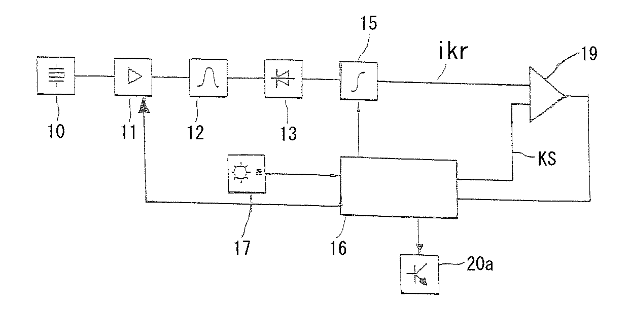
図3は、内燃機関におけるノッキングを識別する装置の一例を示し、これを用いて本発明の方法も実施することができる。詳細には、参照記号10はノッキングセンサを表し、このノッキングセンサ10は内燃機関のシリンダに配置されており、シリンダ内のノイズないし内燃機関のノイズを検知し、このノイズに依存する出力信号を供給する。検知されたノイズは調節可能な増幅器11及びフィルタ12を介して復調回路13に供給される。
FIG. 3 shows an example of a device for identifying knocking in an internal combustion engine, which can also be used to implement the method of the present invention. In detail, the
復調回路13の整流器は積分器15と接続されている。増幅係数を調節することにより、出力信号の基準レベルを十分に一定に、且つ、エンジン回転数に依存せずに保つことができる。積分器15はクランクシャフトと同期する測定ウィンドウの間に測定信号ikrを形成し、この測定ウィンドウは回転数発生器17の出力信号に依存して制御装置16によって形成される。測定信号は比較器19において、制御装置によって設定されたノッキング閾値KSと比較され、比較器19の出力信号はノッキング識別信号として使用される。ノッキング調節のために制御装置16から、該当するシリンダにおける点火をトリガするための出力信号が出力段20aに供給される。
The rectifier of the
フィルタ12の特性は可変である。例えば、バンドパスフィルタを例えば制御装置16の適切な制御パルスによって、所定の周波数が通過帯域内にあるように切り換えることができる。切換ないし周波数変化を、例えば制御装置16のマイクロプロセッサの相応の制御パルスによってトリガすることができる。例えばその周波数において除去すべきバックグラウンドノイズは回転数に依存しているので、フィルタ特性は回転数に依存して変化される、ないし切り換えられる。
The characteristics of the
フィルタ装置、整流器及び積分器、必要に応じて別の構成素子をディジタル及び/又はアナログ、またアナログ素子とディジタル素子を組み合わせても実現することができ、内燃機関の制御装置16、例えば制御装置のプロセッサにも組み込むことができる。必要なステップは例えば同様に制御装置16において実行される。制御装置16、例えば内燃機関の慣例の制御装置は、本発明による方法を実施する適切なプロセッサ手段及びメモリ手段を有する。
The filter device, the rectifier and the integrator, and if necessary, other components can be realized digitally and / or analog, or a combination of analog and digital elements. It can also be incorporated into a processor. The necessary steps are executed in the
Claims (8)
少なくとも1つのノッキングセンサ(1a,1b,...,1n)を用いて、少なくとも1つの前記シリンダにおける燃焼に基づき生じる信号を検知し、
評価回路(20)を用いて前記ノッキングセンサによって検知された前記信号を評価し、
前記評価回路(20)に組み込まれているバンドパスフィルタ(25)を用いて、前記信号を評価するために前記信号の周波数帯域を選定する、方法において、
燃焼が行われている現在のシリンダを識別し、
前記バンドパスフィルタの通過帯域の上側のコーナー周波数及び/又は下側のコーナー周波数を前記現在のシリンダに合わせて変化させ、
前記現在のシリンダに関する情報に基づいて相対的なノッキング強度の算出のためのシリンダ固有の基準値を生成し、前記バンドパスフィルタの通過帯域を変化させる際に、前記基準値を適合させるための追従係数(N)を所定の追従補正係数と乗算する
ことを特徴とする、シリンダを備えた内燃機関のノッキングを識別する方法。 A method for identifying knocking of an internal combustion engine having a plurality of cylinders, comprising:
Using at least one knocking sensor (1a, 1b,..., 1n) to detect a signal resulting from combustion in at least one of the cylinders;
Evaluating the signal detected by the knocking sensor using an evaluation circuit (20);
In a method of selecting a frequency band of the signal to evaluate the signal using a bandpass filter (25) incorporated in the evaluation circuit (20),
Identify the current cylinder where the combustion is taking place,
Changing the upper corner frequency and / or the lower corner frequency of the pass band of the bandpass filter to match the current cylinder ;
A cylinder-specific reference value for calculating a relative knocking strength is generated based on information on the current cylinder, and tracking is performed to adapt the reference value when changing a pass band of the band-pass filter. A method for identifying knocking of an internal combustion engine with a cylinder, characterized in that the coefficient (N) is multiplied by a predetermined tracking correction coefficient .
少なくとも1つの前記シリンダにおける燃焼によって生じる信号を検知する少なくとも1つのノッキングセンサ(1a,1b,...,1n)が設けられており、
前記ノッキングセンサによって検知された信号を評価する評価回路(20)が設けられており、
前記評価回路にはバンドパスフィルタ(25)が設けられていて、前記信号を評価するために前記信号の周波数帯域が選定可能である、装置において、
シリンダ識別ユニット(40)が設けられており、燃焼が行われている現在のシリンダを識別し、
制御ユニット(31)が設けられており、
該制御ユニット(31)によって、前記バンドパスフィルタの通過帯域の上側のコーナー周波数及び/又は下側のコーナー周波数を前記現在のシリンダに合わせて変化させ、
前記メモリユニット(37)は追従補正係数を包含し、該追従補正係数は前記バンドパスフィルタの通過帯域を変化させる際に前記現在のシリンダに関する情報に基づく相対的なノッキング強度の算出のためのシリンダ固有の基準値に対する追従係数(N)と乗算される、ことを特徴とする、シリンダを備えた内燃機関のノッキングを識別する装置。 An apparatus for identifying knocking of an internal combustion engine having a plurality of cylinders,
At least one knocking sensor (1a, 1b,..., 1n) is provided for detecting a signal generated by combustion in at least one of the cylinders;
An evaluation circuit (20) for evaluating a signal detected by the knocking sensor is provided,
In the apparatus, wherein the evaluation circuit is provided with a bandpass filter (25), and a frequency band of the signal can be selected to evaluate the signal,
A cylinder identification unit (40) is provided to identify the current cylinder in which combustion is taking place;
A control unit (31) is provided,
The control unit (31) changes the upper corner frequency and / or the lower corner frequency of the passband of the bandpass filter according to the current cylinder ,
The memory unit (37) includes a tracking correction coefficient, and the tracking correction coefficient is a cylinder for calculating a relative knocking intensity based on information on the current cylinder when changing a pass band of the bandpass filter. Device for identifying knocking of an internal combustion engine with a cylinder, characterized in that it is multiplied by a tracking factor (N) with respect to a specific reference value .
該メモリユニット(37)は、回転数及び/又はシリンダ番号に依存する、前記バンドパスフィルタの中間周波数及び/又は下側のコーナー周波数及び/又は上側のコーナー周波数をそれぞれ特性マップ内に包含する、請求項5または6記載の装置。 The microcomputer (30) is provided with a memory unit (37),
The memory unit (37) includes in the characteristic map the intermediate frequency and / or the lower corner frequency and / or the upper corner frequency of the bandpass filter, depending on the rotational speed and / or cylinder number, respectively. Apparatus according to claim 5 or 6 .
Applications Claiming Priority (4)
| Application Number | Priority Date | Filing Date | Title |
|---|---|---|---|
| DE10040059 | 2000-08-11 | ||
| DE10040059.0 | 2000-08-11 | ||
| DE10043363.4 | 2000-09-02 | ||
| DE10043363 | 2000-09-02 |
Related Parent Applications (1)
| Application Number | Title | Priority Date | Filing Date |
|---|---|---|---|
| JP2002519905A Division JP5279162B2 (en) | 2000-08-11 | 2001-08-03 | Method for identifying knocking in an internal combustion engine |
Publications (2)
| Publication Number | Publication Date |
|---|---|
| JP2011140960A JP2011140960A (en) | 2011-07-21 |
| JP5586521B2 true JP5586521B2 (en) | 2014-09-10 |
Family
ID=26006715
Family Applications (3)
| Application Number | Title | Priority Date | Filing Date |
|---|---|---|---|
| JP2002519905A Expired - Fee Related JP5279162B2 (en) | 2000-08-11 | 2001-08-03 | Method for identifying knocking in an internal combustion engine |
| JP2011096360A Expired - Fee Related JP5586521B2 (en) | 2000-08-11 | 2011-04-22 | Method and apparatus for identifying knocking of an internal combustion engine with at least one cylinder |
| JP2011233229A Pending JP2012017745A (en) | 2000-08-11 | 2011-10-24 | Method and apparatus for recognizing knocking in internal combustion engine |
Family Applications Before (1)
| Application Number | Title | Priority Date | Filing Date |
|---|---|---|---|
| JP2002519905A Expired - Fee Related JP5279162B2 (en) | 2000-08-11 | 2001-08-03 | Method for identifying knocking in an internal combustion engine |
Family Applications After (1)
| Application Number | Title | Priority Date | Filing Date |
|---|---|---|---|
| JP2011233229A Pending JP2012017745A (en) | 2000-08-11 | 2011-10-24 | Method and apparatus for recognizing knocking in internal combustion engine |
Country Status (6)
| Country | Link |
|---|---|
| US (1) | US7051711B2 (en) |
| EP (1) | EP1309841B1 (en) |
| JP (3) | JP5279162B2 (en) |
| KR (2) | KR100828963B1 (en) |
| DE (2) | DE50107442D1 (en) |
| WO (1) | WO2002014822A1 (en) |
Families Citing this family (26)
| Publication number | Priority date | Publication date | Assignee | Title |
|---|---|---|---|---|
| DE10300133A1 (en) | 2003-01-07 | 2004-07-15 | Robert Bosch Gmbh | Signal processing device and control device for cooperation with a signal processing device |
| JP4355254B2 (en) * | 2004-05-14 | 2009-10-28 | 三菱電機株式会社 | Knocking detection device for internal combustion engine |
| DE102005006491B4 (en) * | 2005-02-12 | 2008-09-04 | Audi Ag | Method and device for controlling cam profiles of a camshaft of a multi-cylinder internal combustion engine |
| US7383816B2 (en) * | 2006-01-09 | 2008-06-10 | Dresser, Inc. | Virtual fuel quality sensor |
| JP4773888B2 (en) | 2006-06-02 | 2011-09-14 | 本田技研工業株式会社 | Ignition timing control device for internal combustion engine |
| JP4427071B2 (en) * | 2007-04-17 | 2010-03-03 | 三菱電機株式会社 | Control device for internal combustion engine |
| FR2916803A3 (en) * | 2007-05-30 | 2008-12-05 | Renault Sas | Combustion noise determining device for e.g. oil engine of motor vehicle, has filtering module implementing band-pass function by low-pass module and high-pass module, whose cut-off frequency is less than that of low-pass module |
| DE102007036277A1 (en) | 2007-07-31 | 2009-02-05 | Technische Universität Berlin | Method and device for automatic pattern recognition |
| DE102007049150A1 (en) | 2007-10-12 | 2009-04-16 | Robert Bosch Gmbh | Knock detection system and method for gain control of a knock signal |
| US9157825B2 (en) | 2008-05-01 | 2015-10-13 | GM Global Technology Operations LLC | Engine knock diagnostic |
| US8108128B2 (en) * | 2009-03-31 | 2012-01-31 | Dresser, Inc. | Controlling exhaust gas recirculation |
| DE102010035422B4 (en) * | 2010-08-26 | 2014-02-13 | Borgwarner Beru Systems Gmbh | Ignition device for an internal combustion engine |
| FR2969699B1 (en) * | 2010-12-23 | 2015-07-17 | Renault Sa | SYSTEM FOR MONITORING THE OPERATION OF AN INTERNAL COMBUSTION ENGINE OF A MOTOR VEHICLE. |
| US9523322B2 (en) * | 2012-12-14 | 2016-12-20 | Continental Automotive Systems, Inc. | Method to reduce engine combustion and harmonic noise for misfire detection |
| US9441556B2 (en) * | 2013-03-15 | 2016-09-13 | GM Global Technology Operations LLC | Noise updating systems and methods |
| DE102014102324A1 (en) * | 2014-02-24 | 2015-08-27 | Dr. Ing. H.C. F. Porsche Aktiengesellschaft | Method for detecting a knocking combustion of an internal combustion engine |
| DE102014224799A1 (en) | 2014-12-03 | 2016-06-09 | Inficon Gmbh | Leak test with carrier gas in foil chamber |
| JP6289543B2 (en) * | 2016-06-07 | 2018-03-07 | 三菱電機株式会社 | Control device and control method for internal combustion engine |
| DE102016117155B4 (en) | 2016-09-13 | 2018-06-14 | Iav Gmbh Ingenieurgesellschaft Auto Und Verkehr | Method and device for knock detection during operation of an internal combustion engine |
| DE102017204399B4 (en) | 2017-03-16 | 2022-10-20 | Vitesco Technologies GmbH | Method and device for detecting knocking in an internal combustion engine |
| DE102017204864B4 (en) | 2017-03-23 | 2021-05-20 | Vitesco Technologies GmbH | Method and device for detecting knocking of an internal combustion engine |
| DE102017223532B4 (en) * | 2017-12-21 | 2019-11-14 | Robert Bosch Gmbh | Method and device for knock control of an internal combustion engine |
| US10975828B2 (en) * | 2018-05-21 | 2021-04-13 | Ford Global Technologies, Llc | Method and system for adjusting engine knock background noise levels |
| US11255288B2 (en) * | 2018-05-23 | 2022-02-22 | Ford Global Technologies, Llc | Method and system for determining engine knock background noise levels |
| DE112019002425T5 (en) * | 2018-08-30 | 2021-02-11 | Hitachi Automotive Systems, Ltd. | SIGNAL PROCESSING DEVICE AND POWER MACHINE CONTROL DEVICE |
| DE102023126072B3 (en) | 2023-09-26 | 2024-07-18 | Bayerische Motoren Werke Aktiengesellschaft | Method for knock detection, knock detection system for an internal combustion engine, internal combustion engine and motor vehicle |
Family Cites Families (18)
| Publication number | Priority date | Publication date | Assignee | Title |
|---|---|---|---|---|
| US4345558A (en) * | 1979-04-28 | 1982-08-24 | Nippon Soken, Inc. | Knock detecting apparatus for an internal combustion engine |
| DE3434823A1 (en) * | 1984-09-22 | 1986-04-03 | Robert Bosch Gmbh, 7000 Stuttgart | METHOD FOR KNOCKING CONTROL OF INTERNAL COMBUSTION ENGINES |
| JPS6454227A (en) * | 1987-08-25 | 1989-03-01 | Mazda Motor | Knocking detector for engine |
| JPH0684744B2 (en) * | 1989-10-30 | 1994-10-26 | 三菱電機株式会社 | Knock control device for internal combustion engine |
| DE59008539D1 (en) * | 1990-05-28 | 1995-03-30 | Siemens Ag | Process for cylinder-selective knock control of internal combustion engines. |
| KR940001938B1 (en) * | 1990-08-24 | 1994-03-11 | 미쯔비시 덴끼 가부시기가이샤 | Knocking control device for internal combustion engine |
| JPH04103876A (en) * | 1990-08-24 | 1992-04-06 | Mitsubishi Electric Corp | Knock control device for internal combustion engine |
| US5144929A (en) * | 1990-10-02 | 1992-09-08 | Mitsubishi Denki Kabushiki Kaisha | Knock suppression apparatus and method for a multi-cylinder internal combusiton engine |
| DE4201567A1 (en) | 1992-01-22 | 1993-07-29 | Bosch Gmbh Robert | DEVICE FOR DETECTING THE KNOCK OF AN INTERNAL COMBUSTION ENGINE |
| US5522254A (en) * | 1992-12-04 | 1996-06-04 | Nippondenso Co., Ltd. | Knock sensing apparatus for internal combustion engine |
| JPH06200859A (en) * | 1992-12-28 | 1994-07-19 | Fujitsu Ten Ltd | Knocking control method and its device |
| DE4333965A1 (en) * | 1993-10-05 | 1995-04-06 | Bosch Gmbh Robert | Knock detection method |
| JP3341391B2 (en) * | 1993-10-06 | 2002-11-05 | 株式会社デンソー | Knock detection device for internal combustion engine |
| JP3799618B2 (en) * | 1994-10-21 | 2006-07-19 | 株式会社デンソー | Signal processing circuit |
| JPH08151951A (en) * | 1994-11-29 | 1996-06-11 | Toyota Motor Corp | Knocking control device for internal combustion engine |
| DE19545649A1 (en) | 1994-12-30 | 1996-07-04 | Bosch Gmbh Robert | Device for fault detection in the event of a knock detection |
| DE19549175A1 (en) * | 1995-12-30 | 1997-07-03 | Bosch Gmbh Robert | Knock control method in internal combustion engines |
| JP4364412B2 (en) * | 2000-07-14 | 2009-11-18 | 株式会社デンソー | Knock control device for internal combustion engine |
-
2001
- 2001-08-03 US US10/344,469 patent/US7051711B2/en not_active Expired - Fee Related
- 2001-08-03 EP EP01964879A patent/EP1309841B1/en not_active Expired - Lifetime
- 2001-08-03 KR KR1020077025103A patent/KR100828963B1/en active IP Right Grant
- 2001-08-03 JP JP2002519905A patent/JP5279162B2/en not_active Expired - Fee Related
- 2001-08-03 DE DE50107442T patent/DE50107442D1/en not_active Expired - Lifetime
- 2001-08-03 KR KR1020037001921A patent/KR100828958B1/en active IP Right Grant
- 2001-08-03 WO PCT/DE2001/002962 patent/WO2002014822A1/en active IP Right Grant
- 2001-08-03 DE DE10138110A patent/DE10138110A1/en not_active Withdrawn
-
2011
- 2011-04-22 JP JP2011096360A patent/JP5586521B2/en not_active Expired - Fee Related
- 2011-10-24 JP JP2011233229A patent/JP2012017745A/en active Pending
Also Published As
| Publication number | Publication date |
|---|---|
| KR20070116947A (en) | 2007-12-11 |
| WO2002014822A1 (en) | 2002-02-21 |
| JP2012017745A (en) | 2012-01-26 |
| EP1309841A1 (en) | 2003-05-14 |
| JP2004506847A (en) | 2004-03-04 |
| JP5279162B2 (en) | 2013-09-04 |
| KR100828963B1 (en) | 2008-05-14 |
| KR100828958B1 (en) | 2008-05-13 |
| US20040030486A1 (en) | 2004-02-12 |
| DE50107442D1 (en) | 2005-10-20 |
| EP1309841B1 (en) | 2005-09-14 |
| DE10138110A1 (en) | 2002-03-21 |
| US7051711B2 (en) | 2006-05-30 |
| JP2011140960A (en) | 2011-07-21 |
| KR20030040390A (en) | 2003-05-22 |
Similar Documents
| Publication | Publication Date | Title |
|---|---|---|
| JP5586521B2 (en) | Method and apparatus for identifying knocking of an internal combustion engine with at least one cylinder | |
| US6912460B2 (en) | Method for detecting knock in an internal combustion engine | |
| JP4499330B2 (en) | Method for knocking identification | |
| RU2265744C2 (en) | Method of and device for detecting troubles basing on diagnosing provided by detonation combustion sensor | |
| US4478068A (en) | Internal combustion engine knock sensing method and system | |
| EP2339313B1 (en) | Device and method for determining knock in an internal combustion engine | |
| JPH0447774B2 (en) | ||
| US6145491A (en) | Method for detecting combustion knock from the ionic current in an internal combustion engine | |
| JP2004353531A (en) | Knock control device of internal combustion engine | |
| US5743233A (en) | Method for detecting knocking | |
| US5109820A (en) | Apparatus and method for controlling knocking in an internal combustion engine | |
| JPH0819890B2 (en) | Knocking detection device and ignition timing correction device for internal combustion engine | |
| JPH0312249B2 (en) | ||
| JP3502580B2 (en) | Knock detection device for internal combustion engine | |
| US5522254A (en) | Knock sensing apparatus for internal combustion engine | |
| CN111344478A (en) | Method and device for knock control of an internal combustion engine | |
| JPS6193271A (en) | Method of adjusting knocking of internal combustion engine | |
| KR100286888B1 (en) | Ignition timing control device and method using knock sensor in vehicle | |
| JP4390939B2 (en) | Knock control device for internal combustion engine | |
| US20020050270A1 (en) | Diagnostic process for use in evaluation of sensor signals, especially knock sensor signals | |
| JP2003278592A (en) | Knock control device of internal combustion engine | |
| JPS60263830A (en) | Knocking detecting method of internal-combustion engine | |
| JPS6234028A (en) | Apparatus for discriminating abnormality of cylinder internal pressure sensor | |
| JPH05248305A (en) | Knocking controller | |
| JP4487453B2 (en) | Knocking detection device for internal combustion engine |
Legal Events
| Date | Code | Title | Description |
|---|---|---|---|
| A621 | Written request for application examination |
Free format text: JAPANESE INTERMEDIATE CODE: A621 Effective date: 20110422 |
|
| A131 | Notification of reasons for refusal |
Free format text: JAPANESE INTERMEDIATE CODE: A131 Effective date: 20120725 |
|
| A977 | Report on retrieval |
Free format text: JAPANESE INTERMEDIATE CODE: A971007 Effective date: 20120726 |
|
| A601 | Written request for extension of time |
Free format text: JAPANESE INTERMEDIATE CODE: A601 Effective date: 20121023 |
|
| A602 | Written permission of extension of time |
Free format text: JAPANESE INTERMEDIATE CODE: A602 Effective date: 20121026 |
|
| A521 | Written amendment |
Free format text: JAPANESE INTERMEDIATE CODE: A523 Effective date: 20130123 |
|
| A601 | Written request for extension of time |
Free format text: JAPANESE INTERMEDIATE CODE: A601 Effective date: 20130909 |
|
| A602 | Written permission of extension of time |
Free format text: JAPANESE INTERMEDIATE CODE: A602 Effective date: 20130912 |
|
| A521 | Written amendment |
Free format text: JAPANESE INTERMEDIATE CODE: A523 Effective date: 20131210 |
|
| TRDD | Decision of grant or rejection written | ||
| A01 | Written decision to grant a patent or to grant a registration (utility model) |
Free format text: JAPANESE INTERMEDIATE CODE: A01 Effective date: 20140623 |
|
| A61 | First payment of annual fees (during grant procedure) |
Free format text: JAPANESE INTERMEDIATE CODE: A61 Effective date: 20140722 |
|
| R150 | Certificate of patent or registration of utility model |
Ref document number: 5586521 Country of ref document: JP Free format text: JAPANESE INTERMEDIATE CODE: R150 |
|
| R250 | Receipt of annual fees |
Free format text: JAPANESE INTERMEDIATE CODE: R250 |
|
| R250 | Receipt of annual fees |
Free format text: JAPANESE INTERMEDIATE CODE: R250 |
|
| R250 | Receipt of annual fees |
Free format text: JAPANESE INTERMEDIATE CODE: R250 |
|
| LAPS | Cancellation because of no payment of annual fees |