JP5583726B2 - Test apparatus and test method - Google Patents
Test apparatus and test method Download PDFInfo
- Publication number
- JP5583726B2 JP5583726B2 JP2012207622A JP2012207622A JP5583726B2 JP 5583726 B2 JP5583726 B2 JP 5583726B2 JP 2012207622 A JP2012207622 A JP 2012207622A JP 2012207622 A JP2012207622 A JP 2012207622A JP 5583726 B2 JP5583726 B2 JP 5583726B2
- Authority
- JP
- Japan
- Prior art keywords
- data
- communication
- processing unit
- test
- log
- Prior art date
- Legal status (The legal status is an assumption and is not a legal conclusion. Google has not performed a legal analysis and makes no representation as to the accuracy of the status listed.)
- Active
Links
Images


Classifications
-
- H—ELECTRICITY
- H04—ELECTRIC COMMUNICATION TECHNIQUE
- H04W—WIRELESS COMMUNICATION NETWORKS
- H04W24/00—Supervisory, monitoring or testing arrangements
-
- H—ELECTRICITY
- H04—ELECTRIC COMMUNICATION TECHNIQUE
- H04M—TELEPHONIC COMMUNICATION
- H04M1/00—Substation equipment, e.g. for use by subscribers
- H04M1/24—Arrangements for testing
Description
本発明は、携帯電話機等の移動体の通信端末機器の試験を行う試験装置及び試験方法に関する。 The present invention relates to a test apparatus and a test method for testing a mobile communication terminal device such as a mobile phone.
携帯電話機やモバイル機器等の通信端末機器が新たに開発される場合、この通信端末機器が実際に使用される環境で正常に動作するか否かを試験する必要がある。そして、開発中の通信端末機器が設計通りに機能するか否かを試験する場合には、試験装置を用いてその通信端末機器の試験を行う。 When a communication terminal device such as a mobile phone or a mobile device is newly developed, it is necessary to test whether or not the communication terminal device operates normally in an environment where it is actually used. When testing whether a communication terminal device under development functions as designed, the communication terminal device is tested using a test apparatus.
このような試験装置は、疑似的な基地局として機能し、所定の通信規格の通信プロトコルに基づいて、通信端末機器との間で通信を行う。この場合、試験装置は、通信プロトコルに基づくレイヤごとに、その通信のログ情報を記憶している(例えば、特許文献1参照)。 Such a test apparatus functions as a pseudo base station and performs communication with a communication terminal device based on a communication protocol of a predetermined communication standard. In this case, the test apparatus stores log information of the communication for each layer based on the communication protocol (see, for example, Patent Document 1).
試験装置は、試験シナリオ(試験を行うための通信シーケンス及び動作シーケンスが記載されたデータ)にしたがって動作する。試験者は、予め自ら試験シナリオを作成したり、実際の通信のログ情報を取得し、そのログ情報を基に試験シナリオを作成(ログ−シナリオ変換)したりする。試験シナリオの作成においては、試験シナリオを作成、編集するシナリオ変換装置が用いられる場合がある(例えば、特許文献2参照)。 The test apparatus operates according to a test scenario (data in which a communication sequence and an operation sequence for performing a test are described). The tester creates a test scenario in advance, acquires log information of actual communication, and creates a test scenario (log-scenario conversion) based on the log information. In creating a test scenario, a scenario conversion device that creates and edits a test scenario may be used (see, for example, Patent Document 2).
試験者は、作成した試験シナリオを試験装置に実行させ、例えば表示部に表示された通信のログ情報を確認することができる。そして、例えばログ情報に異常が発生した場合や、試験シナリオに再確認が必要な箇所があった場合、試験者は、試験シナリオを試験装置に再度実行させ、異常の原因を究明している。 The tester can cause the test apparatus to execute the created test scenario, and can confirm, for example, communication log information displayed on the display unit. For example, when an abnormality occurs in the log information or when there is a part that needs to be reconfirmed in the test scenario, the tester causes the test apparatus to execute the test scenario again and investigates the cause of the abnormality.
しかしながら、試験シナリオによる試験においては、試験完了まで長時間を要する場合もある。例えば異常箇所が試験シナリオの後半にあるような場合は、再度、試験シナリオを実行してから異常箇所に至るまでに、何時間もかかる場合もある。試験者が試験シナリオを修正することでデータ量を小さくし、この修正後の試験シナリオを試験装置に再度実行させたとしても、その修正のための手間及び時間が必要となる。 However, in a test based on a test scenario, it may take a long time to complete the test. For example, when the abnormal part is in the latter half of the test scenario, it may take many hours from the execution of the test scenario to the abnormal part again. Even if the tester modifies the test scenario to reduce the amount of data and causes the test apparatus to execute the modified test scenario again, labor and time for the modification are required.
以上のような事情に鑑み、本発明の目的は、再現試験の時間を短縮でき、再現試験に必要な労力を軽減することができる試験装置及び試験方法を提供することにある。 In view of the circumstances as described above, an object of the present invention is to provide a test apparatus and a test method capable of reducing the time required for a reproduction test and reducing labor required for the reproduction test.
上記目的を達成するため、本発明に係る試験装置50は、メッセージ処理部53と、レイヤ処理部54と、通信部55と、ログデータ生成部56と、処理部51とを具備する。
In order to achieve the above object, the
前記メッセージ処理部は、試験シナリオにしたがって、試験対象である移動体通信端末機器10に送信すべきメッセージを生成可能である。
The message processing unit can generate a message to be transmitted to the mobile
前記レイヤ処理部は、通信プロトコルに基づいて、前記生成されたメッセージのデータをレイヤ毎に処理する。 The layer processing unit processes the generated message data for each layer based on a communication protocol.
前記通信部は、前記レイヤ処理部により処理された前記メッセージのデータを、前記移動体通信端末機器に送信可能である。 The communication unit can transmit data of the message processed by the layer processing unit to the mobile communication terminal device.
前記ログデータ生成部は、前記レイヤ処理部による前記レイヤ間の通信データのログを、ログデータとして生成する。 The log data generation unit generates a log of communication data between the layers by the layer processing unit as log data.
前記処理部は、前記生成されたログデータのうち、操作者により指定された任意のログデータに関連する前記通信データを前記レイヤ処理部に出力する。 The processing unit outputs the communication data related to arbitrary log data designated by an operator among the generated log data to the layer processing unit.
処理部は、レイヤ処理部により処理されたレイヤごとのログデータのうち、操作者により指定された任意のログデータに関連する通信データを再度送信する。すなわち、試験装置は、試験シナリオのデータのうち、操作者によって指定された箇所のシナリオ(メッセージ)の動作を再現することができる。これにより、再現試験の時間を短縮でき、試験シナリオを修正する必要もないので試験に必要な試験者の労力を軽減することができる。 The processing unit again transmits communication data related to arbitrary log data designated by the operator among the log data for each layer processed by the layer processing unit. That is, the test apparatus can reproduce the operation of the scenario (message) at the location designated by the operator in the test scenario data. As a result, the time required for the reproduction test can be shortened, and the labor of the tester required for the test can be reduced because there is no need to correct the test scenario.
前記処理部は、前記指定されたログデータに含まれるログヘッダ情報に基づき、前記通信データの宛先のレイヤを特定し、特定したレイヤに前記通信データを出力してもよい。処理部は、特定した宛先のレイヤへ通信データを出力するので、レイヤ処理部は、特定されたレイヤからレイヤ処理を実行して送信することができる。 The processing unit may specify a destination layer of the communication data based on log header information included in the designated log data, and output the communication data to the specified layer. Since the processing unit outputs the communication data to the specified destination layer, the layer processing unit can execute the layer processing from the specified layer and transmit it.
前記処理部は、前記指定されたログデータに関連する前記通信データを編集するための通信データ編集部511を有し、前記通信データが編集された場合、その編集された通信データを出力してもよい。これにより、試験者は、編集後の通信データでの移動体通信端末機器の応答を確認することができる。
The processing unit includes a communication
前記通信部は、前記レイヤ処理部により処理された前記メッセージのデータのベースバンド信号を送信するデジタルインターフェースを有してもよい。これにより、試験装置は、移動体通信端末機器のRF信号処理部を介さずに、通信試験を行うことができる。 The communication unit may include a digital interface that transmits a baseband signal of the data of the message processed by the layer processing unit. Thereby, the test apparatus can perform a communication test without going through the RF signal processing unit of the mobile communication terminal device.
前記処理部は、前記指定されたログデータに含まれるメッセージに関連する情報を含む前記レイヤ間の通信データのうち、任意の1つの通信データを選択して出力してもよい。これにより、処理部は、指定されたログデータに対応するレイヤ間の通信データを出力する場合に限られない。すなわち、処理部は、指定されたログデータに含まれるメッセージを含む通信データのうち任意の1つを選択すればよい。 The processing unit may select and output any one communication data among the communication data between the layers including information related to a message included in the designated log data. Thereby, a process part is not restricted to the case where the communication data between the layers corresponding to the designated log data are output. That is, the processing unit may select any one of communication data including a message included in designated log data.
前記処理部は、前記レイヤ間の通信データのうち、最下位のレイヤへ出力される通信データを選択してもよい。これにより、レイヤ処理部は、そのメッセージを含む通信データについて、最下位のレイヤからレイヤ処理を実行することができる。 The processing unit may select communication data to be output to the lowest layer among the communication data between the layers. Thereby, the layer processing unit can execute the layer processing from the lowest layer on the communication data including the message.
本発明に係る試験方法は、試験シナリオにしたがって、試験対象である移動体通信端末機器10に送信すべきメッセージを生成することを含む。
The test method according to the present invention includes generating a message to be transmitted to the mobile
通信プロトコルに基づいて、前記生成されたメッセージのデータが、レイヤ処理部54でレイヤ毎に処理される。
Based on the communication protocol, the generated message data is processed for each layer by the
前記レイヤ処理部によるレイヤ間の通信データのログが、ログデータとして生成される。 A log of communication data between layers by the layer processing unit is generated as log data.
前記レイヤ処理部により処理された前記メッセージのデータが、前記移動体通信端末機器に送信される。 The message data processed by the layer processing unit is transmitted to the mobile communication terminal device.
前記生成されたログデータのうち、操作者により指定された任意のログデータに関連する前記通信データが前記レイヤ処理部に出力される。 Of the generated log data, the communication data related to arbitrary log data designated by the operator is output to the layer processing unit.
以上、本発明によれば、再現試験の時間を短縮でき、試験に必要な労力を軽減することができる。 As mentioned above, according to this invention, the time of a reproduction test can be shortened and the labor required for a test can be reduced.
以下、図面を参照しながら、本発明の実施形態を説明する。 Hereinafter, embodiments of the present invention will be described with reference to the drawings.
[第1の実施形態]
(試験装置の構成)
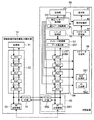
図1は、本発明の一実施形態に係る試験装置50を含むシステムの構成を示すブロック図である。このシステムは、移動体通信端末機器(以下、単に通信端末という。)10と、試験装置50とを含む。
[First Embodiment]
(Configuration of test equipment)
FIG. 1 is a block diagram showing the configuration of a system including a
通信端末10は、携帯電話機、データ通信端末機、又はこれらに用いられる移動体通信用の半導体デバイス等であり、試験装置50による通信試験の対象となる機器である。試験装置50は、疑似基地局として機能し、通信端末10を試験する。
The
試験装置50は、操作部43、表示部41及び表示制御部42を備える。
The
操作部43は、試験者等を含む操作者による操作が入力されるデバイスである。操作部43は、例えばキーボード、マウス、タッチパネル等のデバイスである。
The
表示部41は、表示制御部42により生成された表示画面を表示する。表示部41は、例えば液晶等のデバイスである。
The display unit 41 displays the display screen generated by the
表示制御部42は、表示部41で表示される画面を生成し、特に、ログを表示するための画面を生成する。また、表示制御部42は、操作者が操作部43を介して入力した操作情報を受け、その操作情報に基づいた処理を行う。
The
これら操作部43、表示部41及び表示制御部42は、例えば試験装置50とは別体の装置として設けられ、この別体の装置が試験装置50に接続されてもよい。この別体の装置として、典型的にはPC(Personal Computer)等が用いられる。
For example, the
試験装置50は、シナリオ処理部52、メッセージ処理部53、レイヤ処理部54、ログデータ生成部56、ログデータ記憶部57、特定メッセージ処理部51及び通信部55を備える。
The
シナリオ処理部52は、通信端末10との間で通信試験を行うための試験シナリオのデータであるシナリオファイルを図示しない外部装置から取得してこれを記憶したり、これをメッセージ処理部53に出力したりすることが可能である。外部装置は、例えば図示しない記憶装置や、上記したPC等であり、このシナリオファイルを記憶している。
The
メッセージ処理部53は、シナリオ処理部52から取得した試験シナリオにしたがって、通信端末10に送信すべきメッセージを生成する。また、メッセージ処理部53は、通信端末10からレイヤ処理部54を介して受けたメッセージのデータを処理する。
The
メッセージ処理部53のデータ発生部531は、ユーザデータを含むメッセージの送信が必要な場合に、そのユーザデータを発生する。試験装置50は、予めユーザデータを記憶していてもよいし、外部装置からそれを取得してもよいし、ランダムデータ発生器により発生させてもよい。データ発生部531によりユーザデータが発生した場合、メッセージ処理部53は、そのユーザデータに関連するメッセージを生成する。
The
レイヤ処理部54は、メッセージ処理部53により生成されたメッセージのデータについて、所定の通信規格に対応した通信プロトコル処理(通信プロトコルに基づくレイヤ毎の処理)を行う。レイヤ処理部54は、各レイヤで処理を行う毎に、その通信内容をログデータ生成部56に出力する。レイヤ処理部54は、この通信プロトコル処理により得られたメッセージのデータを通信部55に送り、また、通信端末10から通信部55を介して受けたデータを処理してメッセージ処理部53へ送る。
The
レイヤ処理部54は、例えばLTE(Long Term Evolution)方式の通信プロトコル処理を行う。この場合、レイヤとしては上位から、RRC(Radio Resource Control)、PDCP(Packet Data Control Protocol)、RLC(Radio Link Control)、MAC(Media Access Control)、PHY(PHYsical)がある。
The
これら各レイヤは、ダウンリンクでは、上位から受けた通信データ36にこのレイヤ特有の処理を行い、下位に渡す。各レイヤは、アップリンクでは、下位から受けた通信データにこのレイヤ特有の処理を行い上位に渡す。
In the downlink, each layer performs processing specific to this layer on the
なお、図示していないが、試験装置50は、通信部55、レイヤ処理部54、メッセージ処理部53を複数組、備える構成であっても良い。一組の通信部55、レイヤ処理部54、メッセージ処理部53は、1台の基地局の動作を模擬する。このため、試験装置10がこの組合せを複数備えることにより、例えば、移動体通信端末が通信先の基地局を切り替えるハンドオーバ動作の試験を、1台の試験装置50で行うことができる。なお、この場合は、試験装置50は、各組から送信される信号を結合して通信端末10に出力するとともに通信端末10から受信した信号を各組に分配する結合器(不図示)を備える。
Although not shown, the
ログデータ生成部56は、レイヤ処理部54の各レイヤから出力される通信内容である通信データから、ログデータを生成する。図2は、ログデータの構成を示す。ログデータ30は、ログヘッダ(ログヘッダ情報)35と、レイヤ間の通信データ36とを含む。ログヘッダ35は、後述するID35a、後述する時刻情報35b、レイヤ間の通信データの送信元及び宛先を示す送信元レイヤ35c及び宛先レイヤ35d、通信データのチャネルの種別を示すチャネル情報35e、試験装置50が複数の基地局を模擬する場合にそれらを識別するBTS(Base Transciever Station)番号35f、通信データの設定命令であるプリミティブを示すプリミティブ名35g、可変長である通信データのデータ長を示す通信データ長35hを含む。
The log
図1に示すように、ログデータ生成部56は、時刻生成部561、ID生成部562を有する。時刻生成部561は、時刻情報を生成する。ID生成部562は、ログ(ログデータ30)を識別する識別子(ID35a)を生成する。ID35aは、試験開始からのシーケンスな番号である。
As illustrated in FIG. 1, the log
ログヘッダ35のうち、送信元レイヤ35c、宛先レイヤ35d、チャネル情報35e、BTS番号35f、プリミティブ名35g及び通信データ長35hは、ログデータ生成部56が通信データの送出元を識別する、又はログデータ生成部56が受けた通信データを解析する、あるいはレイヤ処理部54から通信データとともにこれらの情報を送出してもらう、のいずれかの方式又はそれらの組合せにより、ログデータ生成部56がこれらの情報を取得する。ログデータ生成部56は、そのように取得された情報に、ID35a及び時刻情報35bをさらに付加してログヘッダを生成する。
In the
ログデータ記憶部57は、ログデータ生成部56で生成されたログデータ30を記憶する。ログデータ記憶部57は、HDD(Hard Disk Drive)や、フラッシュメモリ等の大容量記憶媒体である。ログデータ記憶部57は、この試験装置50とは別体の外部記憶装置であってもよい。
The log
処理部として機能する特定メッセージ処理部51は、表示制御部42からログデータ30を取得し、このログデータ30に関連する通信データ36をレイヤ処理部54に出力する。あるいは、表示制御部42の代わりに、特定メッセージ処理部51がログデータ記憶部57からログデータ30を取得してもよい。また、表示制御部42の代わりに、特定メッセージ処理部51が、操作部43を介して入力された操作者の操作情報を受け、その操作情報に基づいた処理を行ってもよい。上記表示制御部42及び特定メッセージ処理部51の協働によって処理部が機能してもよい。
The specific
通信データ編集部511は、操作者の操作部43を介して発生した操作情報に基づいて、通信データ36を編集する。操作者により通信データが編集された場合、特定メッセージ処理部51は、編集された通信データ36をレイヤ処理部54に出力する。
The communication
通信部55は、RF送受信部551及びデジタルI/F(デジタルインターフェース)部552を含む。
The
RF送受信部551は、レイヤ処理部54において通信プロトコル処理が実行されたデータを、符号化、変調及び周波数変換してRF信号を生成し、これを通信端末10に送信する。また、RF送受信部551は、通信端末10から送信されたRF信号を受信し、周波数変換、復調及び復号して、これをレイヤ処理部54に送る。通信端末10のRF送受信部13と、試験装置50のRF送受信部551とは、例えば同軸ケーブルにより接続され、RF信号が送受信される。
The RF transmission /
デジタルI/F部552は、レイヤ処理部54において通信プロトコル処理が実行されたデータを、通信端末10に送信する。また、デジタルI/F部552は、通信端末10から送信されたデータを受信し、レイヤ処理部54に送る。通信端末10のデジタルI/F部14と、試験装置50のデジタルI/F部552とは、例えばデジタルケーブルにより接続され、高速通信が可能である。デジタルI/F部552及び14間で通信対象となるデータは、デジタルIQデータであり、すなわちベースバンド信号である。
The digital I /
通信端末10は、最終製品としては一般的にこのデジタルI/F部14を持っていない。しかし、開発デバッグ用としてこのデジタルI/F部14が設けられる場合がある。
The
試験装置50は、図示しないCPU(Central Processing Unit)、RAM(Random Access Memory)、ROM(Read Only Memory)等のハードウェアを主に備える。試験装置50は、CPUに加え、または、CPUに代えて、FPGA(Field Programmable Gate Array)等のPLD(Programmable Logic Device)を備えていてもよいし、あるいは、DSP(Digital Signal Processor)、ASIC(Application Specific Integrated Circuit)等を備えていてもよい。
The
試験装置50の構成は、上記ハードウェアのみで実現されてもよいし、または、ハードウェア及びソフトウェアの両方で実現されてもよい。後者の場合、上記CPU等のプロセッサであるハードウェアと、例えば上記ROMや他の記憶デバイスに記憶されたソフトウェアとの協働により、図1に示した試験装置50の各機能ブロックの機能を実現する。
The configuration of the
通信端末10は、上記通信方式に用いられる同様なレイヤ処理部12を備える。また、通信端末10は、レイヤ処理部12で得られたデータを処理し、処理したデータをレイヤ処理部12へ出力する処理部11と、上記のRF送受信部13及びデジタルI/F部14とを備える。
The
(試験装置の動作)
以上のように構成された試験装置50の動作を説明する。図3は、主にその試験装置50の動作を示すフローチャートである。この動作には、大きく分けて2つの段階がある。1つは、(1)元の試験の段階であり、もう1つは(2)再現試験の段階である。再現試験は、元の試験シナリオによる試験の一部を再現する試験である。
(1)元の試験の段階
試験装置50のシナリオ処理部52は、試験シナリオにしたがって、試験装置50と通信端末10との間で、通信を開始する(ステップ101)。ログデータ生成部56は、各レイヤ間の通信データ36を取得する(ステップ102)。ログデータ記憶部57は、得られた通信データ36のログをログデータ30として記憶する(ステップ103)。
(2)再現試験の段階
試験シナリオによる試験の一部または全部が終了すると、表示制御部42は、表示部41にログデータの一覧の画面を表示する。表示制御部42は、ログデータの画面として、過去の試験(上記元の試験)でのログを示す第1表示画面を表示する(ステップ104)。
(Operation of test equipment)
The operation of the
(1) Original Test Stage The
(2) Stage of reproduction test When a part or all of the test according to the test scenario is completed, the
図4は、その第1表示画面の例を示す。第1表示画面21は、ログヘッダ35の情報を上から下へ時系列に並べて表示するログヘッダ情報表示エリア24と、通信データの内容を表示する通信データ情報表示エリア25とを含む。図4では、大量に生成されるログデータのうちのごく一部を示しており、具体的には、試験装置50側からの1つの送信メッセージに対する通信端末10側からの1つの応答メッセージについてのログデータを示している。
FIG. 4 shows an example of the first display screen. The
ログヘッダ情報表示エリア24は、「No.」、「PHY」〜「RRC」、「Primitive」、「Channel」、「Progress Time」を含む。すなわち、これらは図2で示したログヘッダ35に含まれる情報の内容である。
The log header
「No.」は、個々のログデータ30の識別番号であり、本実施形態ではID35aがそのまま表示される。
“No.” is an identification number of each
「PHY」〜「RRC」は、どのレイヤ間でどちらの方向に流れるデータかを矢印で示す。No.001〜004のログはダウンリンクデータであり、No.005〜008のログはアップリンクデータである。 “PHY” to “RRC” indicate with which arrows data flows in which direction between layers. No. The logs from 001 to 004 are downlink data. The logs from 005 to 008 are uplink data.
「Primitive」は、各レイヤ間の設定命令を示す。 “Primitive” indicates a setting command between layers.
「BTS」は、BTS番号である(疑似)基地局の番号を示す。この試験装置50は、ハンドオーバ関連の試験用に複数の基地局の機能を持つ。
“BTS” indicates a (pseudo) base station number which is a BTS number. The
「Channel」は、どの通信チャネルを用いた通信か示す。 “Channel” indicates which communication channel is used for communication.
「Progress Time」は、時刻生成部561で生成されてログに付された時刻である。
“Progress Time” is the time generated by the
通信データ情報表示エリア25は、「Message」を含む。これは、メッセージ名またはメッセージタイプを示す。
The communication data
本実施形態では、メッセージ名またはメッセージタイプは、最上位レイヤのログでのみ(図4に示す例では、ログNo.001及び008のみ)表示される。しかし、これらは最上位レイヤ以外のレイヤのうち少なくとも1つで表示されてもよい。図4に示す例では、メッセージ名が「RRC CONNECTION RECONFIGURATION」であり、通信端末10からの応答メッセージ(ログNo.008)が「RRC CONNECTION RECONFIGURATION COMPLETE」となっている。
In this embodiment, the message name or message type is displayed only in the log of the highest layer (in the example shown in FIG. 4, only log Nos. 001 and 008). However, these may be displayed in at least one of the layers other than the highest layer. In the example shown in FIG. 4, the message name is “RRC CONNECTION RECONFIGURATION”, and the response message (log No. 008) from the
また、通信データ情報表示エリア25は、この第1表示画面21の下方の2段の欄26及び27で示すように、操作者による操作部43を介した操作により指定されたログの通信データを表示するエリアを含む。その2段の欄26及び27のうち、上段は通信データの変換表示(例えば、"RLC : DL-DTCH-Message : message : C1..."というように表示される )であり、下段のエリアはHEX表示(例えば、"0x 0A E2 FF 35 9B... "というように表示される )である。本実施形態では、通信データは、最上位レイヤのログでのみ(図4に示す例では、ログNo.001及び008のみ)表示される。しかし、これらは最上位レイヤ以外のレイヤのうち少なくとも1つで表示されてもよい。この例では、以下に説明するように、No.003のログデータが操作者により指定され、例えばハイライト表示されている。ハイライト表示は必須ではない。
The communication data
動作の説明に戻る。操作者が第1表示画面21によりログデータを確認する。そして、操作者により、任意の1つのログデータ、ここではNo.003のダウンリンクのログデータが指定されるとする(ステップ105)。そうすると、表示制御部42は指定されたログデータを、特定メッセージ処理部51へ出力する(ステップ106)。
Return to the description of the operation. The operator confirms the log data on the
特定メッセージ処理部51は、取得したログデータに関連する通信データをレイヤ処理部54に出力する。ここでは特定メッセージ処理部51は、そのログデータ30のログヘッダ情報に基づき、この通信データの宛先のレイヤ(35d)を特定し(図2参照)、特定したレイヤにこの通信データを出力する(ステップ107)。図4に示す例では、No.003のログデータが指定されたので、このログデータに含まれる通信データの宛先レイヤは「MAC」である。したがって、特定メッセージ処理部51は、MACレイヤに通信データを出力する。
The specific
ここでステップ107では、操作者は通信データを編集することができる。例えば、通信データ編集部511は、操作者による操作部43を介して入力された操作情報にしたがってその通信データを編集する。例えば、意図的に通信に異常を発生させるように通信データが編集される場合もあるし、あるいは、既に試験者が認識している異常を修正するための編集が行われる場合もある。
Here, in step 107, the operator can edit the communication data. For example, the communication
通信データが編集された場合、特定メッセージ処理部51は、編集後の通信データをレイヤ処理部54へ出力する。このように、通信データを編集可能とすることにより、試験者は、後述する第2表示画面22で、編集後の通信データでの通信端末10の応答を確認することができる。
When the communication data is edited, the specific
レイヤ処理部54は、取得した通信データについてのダウンリンクのレイヤ処理を実行する(ステップ108)。またこの場合、ログデータ生成部56は、元の試験の段階と同様にその時のレイヤ間の通信データのログをログデータとして生成し、ログデータ記憶部57はこれを記憶する。
The
通信部55は、レイヤ処理部54から出力された通信データを、デジタルI/F部552またはRF送受信部551を介して、通信端末10へ送信する(ステップ109)。そして、通信端末10は、その通信データに対する応答処理を実行し、試験装置50へ所定のデータを送信する。通信部55は、通信端末10から送信されたアップリンクのデータを、デジタルI/F部552またはRF送受信部551を介して受信する(ステップ110)。
The
レイヤ処理部54は、通信部55を介して受信したデータのアップリンクのレイヤ処理を実行する(ステップ111)。またこの場合、ログデータ生成部56は、元の試験の段階と同様にその時のレイヤ間の通信データのログをログデータとして生成し、ログデータ記憶部57はこれを記憶する。
The
表示制御部42は、再現試験でのログデータ、つまりステップ108及び111におけるレイヤ処理によるログデータを表示する第2表示画面22を表示する(ステップ112)。図5は、その第2表示画面22の例を示す。第1表示画面21及び第2表示画面22は、並べて表示されたり、切り替えて表示されたりする。
The
この第2表示画面22の例では、MACレイヤの処理から始まるNo.101のログデータについて、例えばハイライト表示がなされている。このハイライト表示されたログデータが、上記操作者により指定されたログデータに対応する。ここでのハイライト表示はなくてもよい。
In the example of the
試験者は、第2表示画面22で表示されるログデータを見ることにより、再現試験の結果を確認することができる。
The tester can confirm the result of the reproduction test by looking at the log data displayed on the
以上のような本実施形態に係る試験装置50が活用されるケースとして、例えば、元の試験段階で、通信端末10からの送られた通信データに、何らかの異常が確認されたケースが考えられる。この場合、第1表示画面21において、最上位のアップリンクのログデータ(No.008)のメッセージ名が、「〜COMPLETE」ではなく、例えば「NACK」、「〜REJECT」、「〜FAILURE」であったりする。しかしながら異常が発生した場合に限られず、試験装置50は、任意のログデータを操作者に指定させることができ、指定されたログデータの通信データを送信することができる。
As a case where the
以上のように、本実施形態では、特定メッセージ処理部51は、レイヤ処理部54により処理されたレイヤ毎のログデータのうち、操作者により指定された任意のログデータに関連する通信データを再度送信する。すなわち、試験装置50は、試験シナリオのデータのうち、操作者によって指定された箇所のシナリオ、つまり試験シナリオの一部の動作を再現することができる。これにより、例えば試験シナリオのすべてを最初から実行する場合に比べ、再現試験の時間を短縮できる。また、試験シナリオの一部を実行するために、試験者が試験シナリオを修正する必要もないので、試験に必要な試験者の労力を軽減することができる。
As described above, in the present embodiment, the specific
また、本実施形態によれば、上記のように試験シナリオを修正する必要がないことから、以下のような効果も得ることができる。すなわち、試験者が試験シナリオの作成者ではなかったり、試験シナリオを作成できない者であったりする場合であっても、シナリオの内容の少なくとも一部を理解できる場合には、その試験者はログデータを指定するだけでよいので、容易に再現試験を行うことができる。 Moreover, according to this embodiment, since it is not necessary to correct a test scenario as mentioned above, the following effects can also be acquired. In other words, even if the tester is not the creator of the test scenario or is unable to create the test scenario, if the tester can understand at least part of the scenario contents, the tester will log data. Since it is only necessary to specify, it is possible to easily perform a reproduction test.
ここで、試験シナリオを最初から再度実行しても、その再現試験の条件が、元の試験の条件と全く同一とならない場合がある。例えば、エラーレートの測定試験において、通信端末10に送信するユーザデータ(例えば、メール内容のデータ、動画データ等)の模擬データとして、PN符号のランダムデータを用いた場合、試験シナリオを実行する度に、通信データ36が変わってしまう。これに対して、本実施形態では、元の試験の通信データを用いるので、元の試験と再現試験とにおける通信データ36を同一とすることができる。つまり、試験条件の同一性が高められるので、再現性が向上する。
Here, even if the test scenario is executed again from the beginning, the conditions of the reproduction test may not be exactly the same as the conditions of the original test. For example, in the error rate measurement test, when random data of a PN code is used as simulated data of user data (for example, mail content data, moving image data, etc.) transmitted to the
本実施形態では、操作者が任意のログデータを指定できるようにしたことによって、最上位のログデータを指定する場合に限られず、最上位以外の途中のレイヤ間のログデータが指定された場合に、その指定されたログデータの宛先レイヤからの再現試験を行うことができる。これにより、レイヤ処理部54による処理効率が向上し(処理数が減り)、また、処理時間を短縮することができる。
In this embodiment, by enabling the operator to specify arbitrary log data, not only when specifying the highest level log data, but also when log data between intermediate layers other than the highest level is specified In addition, it is possible to perform a reproduction test of the designated log data from the destination layer. Thereby, the processing efficiency by the
また、本実施形態では、操作者が任意のレイヤの通信データを編集して送出できるようにしたことによって、各レイヤの処理に起因する異常の原因の特定が容易になる。 In the present embodiment, the operator can edit and send out communication data of an arbitrary layer, so that it becomes easy to identify the cause of an abnormality caused by the processing of each layer.
本実施形態に係る試験装置50は、デジタルI/F部552でデータを送受信できるので、通信端末10のRF送受信部13が未完成でも、通信試験を行うことができる。あるいは、RF信号処理における異常要因を除去して通信試験を行うことができる。
Since the
[第2の実施形態]
本発明の第2の実施形態に係る試験装置の動作を説明する。図6は、その動作による再現試験の結果のログデータの表示画面(第2表示画面)を示す。この第2の実施形態において、上記第1の実施形態で示した試験装置50の機能及び動作等について、同様のものは説明を簡略化または省略し、異なる点を中心に説明する。
[Second Embodiment]
The operation of the test apparatus according to the second embodiment of the present invention will be described. FIG. 6 shows a display screen (second display screen) of log data as a result of the reproduction test by the operation. In the second embodiment, description of functions and operations of the
本実施形態に係る試験では、まず、図3に示したステップ101〜106が実行される。特定メッセージ処理部51は、ステップ106で指定されたログデータ30に含まれるメッセージに関連する情報を含む、レイヤ間の各通信データのうち、任意の1つの通信データを選択して、対応するレイヤへ出力する。メッセージに関連する情報とは、つまりメッセージ名やメッセージ内容等である。本動作では、指定されたログデータ内のメッセージと同一メッセージ内容を持つ(各レイヤ間の)通信データのうち、任意の1つの通信データが選択されて出力される。
In the test according to the present embodiment, first, steps 101 to 106 shown in FIG. 3 are executed. The specific
例えば、操作者が図4に示したようにNo.003(あるいはNo.001でもよい)のログデータを指定すると、特定メッセージ処理部51は、No.001〜004のログデータのうち任意の1つのログデータの通信データをレイヤ処理部54に出力する。
For example, as shown in FIG. When the log data of 003 (or No. 001) may be designated, the specific
図6に示した第2表示画面22の例は、最下位のレイヤ「PHY」へ出力される通信データが選択された結果を示している。このように、4つのダウンリンクのレイヤ間の通信データのログデータのうち任意の1つが操作者により選択された場合、それら4つのレイヤ間の通信データのうち、最下位のレイヤへ出力される通信データが自動で選択される。これにより、レイヤ処理部54による処理効率が向上し、処理時間を短縮することができる。
The example of the
[その他の実施形態]
本発明は、以上説明した実施形態に限定されず、他の種々の実施形態を実現することができる。
[Other Embodiments]
The present invention is not limited to the embodiment described above, and other various embodiments can be realized.
上記各実施形態に係る試験装置を含むシステムは、通信方式としてLTE方式を用いたが、これに限られず、他の通信方式を用いてもよい。 Although the system including the test apparatus according to each of the above embodiments uses the LTE method as a communication method, the communication method is not limited thereto, and other communication methods may be used.
上記実施形態に係る試験装置50の通信部55は、RF送受信部551及びデジタルI/F部552の両方を備えたが、これらのうちいずれか一方のみ備えてもよい。
Although the
上記実施形態に係る通信データ編集部511は、操作者により入力された操作情報に基づいて、指定された通信データを編集した。しかし、通信データ編集部511は、操作者の操作情報によらず、所定のアルゴリズムにしたがって、指定の通信データを編集してもよい。
The communication
以上説明した各形態の特徴部分のうち、少なくとも2つの特徴部分を組み合わせることも可能である。 It is also possible to combine at least two feature portions among the feature portions of each embodiment described above.
10…移動体通信端末機器
11…処理部
12…レイヤ処理部
30…ログデータ
35…ログヘッダ
36…通信データ
50…試験装置
51…特定メッセージ処理部
52…シナリオ処理部
53…メッセージ処理部
54…レイヤ処理部
55…通信部
56…ログデータ生成部
57…ログデータ記憶部
511…通信データ編集部
551…RF送受信部
552…デジタルI/F部
DESCRIPTION OF
Claims (7)
通信プロトコルに基づいて、前記生成されたメッセージのデータをレイヤ毎に処理するレイヤ処理部(54)と、
前記レイヤ処理部により処理された前記メッセージのデータを、前記移動体通信端末機器に送信可能な通信部(55)と、
前記レイヤ処理部による前記レイヤ間の通信データのログを、ログデータとして生成するログデータ生成部(56)と、
前記生成されたログデータのうち、操作者により指定された任意のログデータに関連する前記通信データを前記レイヤ処理部に出力する処理部(51)と
を具備する試験装置。 A message processing unit (53) capable of generating a message to be transmitted to the mobile communication terminal device (10) to be tested according to the test scenario;
A layer processing unit (54) for processing data of the generated message for each layer based on a communication protocol;
A communication unit (55) capable of transmitting the message data processed by the layer processing unit to the mobile communication terminal device;
A log data generation unit (56) for generating a log of communication data between the layers by the layer processing unit as log data;
A test apparatus comprising: a processing unit (51) that outputs the communication data related to arbitrary log data designated by an operator among the generated log data to the layer processing unit.
前記処理部は、前記指定されたログデータに含まれるログヘッダ情報に基づき、前記通信データの宛先のレイヤを特定し、特定したレイヤに前記通信データを出力する
試験装置。 The test apparatus according to claim 1,
The test unit is a test apparatus that specifies a destination layer of the communication data based on log header information included in the designated log data, and outputs the communication data to the specified layer.
前記処理部は、前記指定されたログデータに関連する前記通信データを編集するための通信データ編集部(511)を有し、前記通信データが編集された場合、その編集された通信データを出力する
試験装置。 The test apparatus according to claim 1 or 2, wherein
The processing unit includes a communication data editing unit (511) for editing the communication data related to the designated log data, and outputs the edited communication data when the communication data is edited. Test equipment.
前記通信部は、前記レイヤ処理部により処理された前記メッセージのデータのベースバンド信号を送信するデジタルインターフェースを有する
試験装置。 The test apparatus according to any one of claims 1 to 3,
The test apparatus, wherein the communication unit includes a digital interface that transmits a baseband signal of the data of the message processed by the layer processing unit.
前記処理部は、前記指定されたログデータに含まれるメッセージに関連する情報を含む前記レイヤ間の通信データのうち、任意の1つの通信データを選択して出力する
試験装置。 The test apparatus according to claim 1,
The test apparatus, wherein the processing unit selects and outputs any one communication data among communication data between the layers including information related to a message included in the designated log data.
前記処理部は、前記レイヤ間の通信データのうち、最下位のレイヤへ出力される通信データを選択する
試験装置。 The test apparatus according to claim 5,
The said processing part is a test apparatus which selects the communication data output to the lowest layer among the communication data between the said layers.
通信プロトコルに基づいて、前記生成されたメッセージのデータを、レイヤ処理部でレイヤ毎に処理し、
前記レイヤ処理部(54)によるレイヤ間の通信データのログを、ログデータとして生成し、
前記レイヤ処理部により処理された前記メッセージのデータを、前記移動体通信端末機器に送信し、
前記生成されたログデータのうち、操作者により指定された任意のログデータに関連する前記通信データを前記レイヤ処理部に出力する
試験方法。
According to the test scenario, a message to be transmitted to the mobile communication terminal device (10) to be tested is generated,
Based on the communication protocol, the generated message data is processed for each layer in the layer processing unit,
A log of communication data between layers by the layer processing unit (54) is generated as log data,
The message data processed by the layer processing unit is transmitted to the mobile communication terminal device,
A test method for outputting the communication data related to arbitrary log data designated by an operator from the generated log data to the layer processing unit.
Priority Applications (3)
| Application Number | Priority Date | Filing Date | Title |
|---|---|---|---|
| JP2012207622A JP5583726B2 (en) | 2012-09-20 | 2012-09-20 | Test apparatus and test method |
| CN201310302682.7A CN103685660B (en) | 2012-09-20 | 2013-07-17 | Mobile communication terminal test device and mobile communication terminal method of testing |
| US13/949,752 US20140082439A1 (en) | 2012-09-20 | 2013-07-24 | Test device for mobile communication terminal and test method for mobile communication terminal |
Applications Claiming Priority (1)
| Application Number | Priority Date | Filing Date | Title |
|---|---|---|---|
| JP2012207622A JP5583726B2 (en) | 2012-09-20 | 2012-09-20 | Test apparatus and test method |
Publications (2)
| Publication Number | Publication Date |
|---|---|
| JP2014063323A JP2014063323A (en) | 2014-04-10 |
| JP5583726B2 true JP5583726B2 (en) | 2014-09-03 |
Family
ID=50275775
Family Applications (1)
| Application Number | Title | Priority Date | Filing Date |
|---|---|---|---|
| JP2012207622A Active JP5583726B2 (en) | 2012-09-20 | 2012-09-20 | Test apparatus and test method |
Country Status (3)
| Country | Link |
|---|---|
| US (1) | US20140082439A1 (en) |
| JP (1) | JP5583726B2 (en) |
| CN (1) | CN103685660B (en) |
Families Citing this family (3)
| Publication number | Priority date | Publication date | Assignee | Title |
|---|---|---|---|---|
| JP5934276B2 (en) * | 2014-03-28 | 2016-06-15 | アンリツ株式会社 | Test apparatus and test method |
| US10547526B2 (en) | 2018-05-17 | 2020-01-28 | At&T Intellectual Property I, L.P. | Systems and methods for network analysis and management |
| JP7111664B2 (en) * | 2019-08-06 | 2022-08-02 | アンリツ株式会社 | Measurement device, communication terminal measurement system, and measurement-related information display method |
Family Cites Families (26)
| Publication number | Priority date | Publication date | Assignee | Title |
|---|---|---|---|---|
| JPS63308446A (en) * | 1987-06-10 | 1988-12-15 | Nec Corp | Tracing system for trouble cause |
| JP2578471B2 (en) * | 1988-04-27 | 1997-02-05 | 日本電信電話株式会社 | Multi-layer tracer |
| JP2774223B2 (en) * | 1992-12-22 | 1998-07-09 | 松下電工株式会社 | Protocol verification device |
| JP3212959B2 (en) * | 1998-12-28 | 2001-09-25 | 日本電気通信システム株式会社 | Automatic communication protocol test system having message / sequence editing function and test method |
| JP2000250831A (en) * | 1999-02-26 | 2000-09-14 | Ando Electric Co Ltd | Communication protocol diagnostic method, device therefor and recording medium |
| AU2003227931A1 (en) * | 2002-05-15 | 2003-12-02 | British Telecommunications Public Limited Company | Subscriber line validation of a telephone network |
| JP2004112163A (en) * | 2002-09-17 | 2004-04-08 | Matsushita Electric Ind Co Ltd | Mobile station tester |
| JP3845621B2 (en) * | 2003-03-24 | 2006-11-15 | アンリツ株式会社 | Mobile communication terminal test apparatus and mobile communication terminal test method |
| JP3651850B2 (en) * | 2003-10-21 | 2005-05-25 | アンリツ株式会社 | Mobile communication terminal test equipment |
| DE602005019032D1 (en) * | 2004-03-04 | 2010-03-11 | Anritsu Corp | DEVICE AND METHOD FOR SIMULATING A COMMUNICATION SYSTEM WITH THE ABILITY TO EASILY CONTROL A PROTOCOL MESSAGE |
| US7190978B2 (en) * | 2004-07-02 | 2007-03-13 | Anritsu Corporation | Mobile network simulator apparatus |
| JP2006048767A (en) * | 2004-07-30 | 2006-02-16 | Elpida Memory Inc | Semiconductor memory test apparatus |
| JP2006352290A (en) * | 2005-06-14 | 2006-12-28 | Nec Commun Syst Ltd | Scenario creating apparatus, test system, scenario generating method, and program |
| US20080080536A1 (en) * | 2006-10-02 | 2008-04-03 | Texas Instruments Incorporated | Media access control layer bridging of a real communication device to a simulated network |
| EP2086127B1 (en) * | 2006-10-30 | 2014-10-29 | Anritsu Corporation | Mobile communication terminal transmission power control method and mobile communication terminal transmission power control device |
| JP4686436B2 (en) * | 2006-11-15 | 2011-05-25 | アンリツ株式会社 | Scenario converter |
| JP4951007B2 (en) * | 2007-02-08 | 2012-06-13 | アンリツ株式会社 | Communication test apparatus and communication test method |
| DE102008010290A1 (en) * | 2007-06-27 | 2009-02-19 | Rohde & Schwarz Gmbh & Co. Kg | Mobile radio device testing method, involves analyzing information over mobile radio network by analyzer, converting information to instruction sequence, and simulating mobile radio network by executing part of sequence by protocol tester |
| JP4613193B2 (en) * | 2007-07-19 | 2011-01-12 | アンリツ株式会社 | Signal analyzer |
| US8880056B2 (en) * | 2007-09-03 | 2014-11-04 | Broadcom Corporation | Systems and methods for mobile phone validation |
| JP4686532B2 (en) * | 2007-12-13 | 2011-05-25 | アンリツ株式会社 | Test equipment |
| JP5284240B2 (en) * | 2008-11-10 | 2013-09-11 | アンリツ株式会社 | Mobile terminal test apparatus and mobile terminal test method |
| JP4990314B2 (en) * | 2009-03-17 | 2012-08-01 | アンリツ株式会社 | Pseudo base station equipment |
| JP4860735B2 (en) * | 2009-08-26 | 2012-01-25 | アンリツ株式会社 | Filter unit and mobile communication terminal test system |
| JP4914484B2 (en) * | 2009-12-16 | 2012-04-11 | アンリツ株式会社 | Mobile communication terminal test apparatus and test result display method |
| CN102111470B (en) * | 2011-03-30 | 2013-07-31 | 中国联合网络通信集团有限公司 | Method for detecting wireless transceiving performance of mobile communication terminal |
-
2012
- 2012-09-20 JP JP2012207622A patent/JP5583726B2/en active Active
-
2013
- 2013-07-17 CN CN201310302682.7A patent/CN103685660B/en active Active
- 2013-07-24 US US13/949,752 patent/US20140082439A1/en not_active Abandoned
Also Published As
| Publication number | Publication date |
|---|---|
| CN103685660B (en) | 2016-08-17 |
| US20140082439A1 (en) | 2014-03-20 |
| CN103685660A (en) | 2014-03-26 |
| JP2014063323A (en) | 2014-04-10 |
Similar Documents
| Publication | Publication Date | Title |
|---|---|---|
| JP5213982B2 (en) | Mobile communication terminal test system, analysis method, and analysis program | |
| JP6576400B2 (en) | Mobile terminal test apparatus and parameter changing method thereof | |
| JP5934276B2 (en) | Test apparatus and test method | |
| JP2010531589A (en) | Method for testing a mobile radio device | |
| JP2018201067A (en) | Mobile terminal test device and frequency information setting method therefor | |
| CN103918300B (en) | Analyze the method and its device of link failure reason | |
| JP2006352290A (en) | Scenario creating apparatus, test system, scenario generating method, and program | |
| US20140169177A1 (en) | Methods, systems, and computer readable media for processing multiple control and user data flows at a port processor | |
| JP2014143644A (en) | Test device and test display method | |
| US20140140271A1 (en) | Methods, systems, and computer readable media for rapid decoding of wireless communications network uplink data | |
| JP5583726B2 (en) | Test apparatus and test method | |
| JP6505790B2 (en) | Mobile terminal test apparatus and mobile terminal test method | |
| JP5670486B2 (en) | Test apparatus and test method | |
| JP4064392B2 (en) | Scenario generation device, pseudo base station, scenario generation program, and recording medium | |
| US20210337405A1 (en) | Mobile terminal test device and mobile terminal test method | |
| JP5433753B1 (en) | Test apparatus and test method | |
| JP2008277914A (en) | Mobile communication terminal test device and mobile communication terminal test method | |
| JP5814413B2 (en) | Test apparatus and test method | |
| JP5726923B2 (en) | Test apparatus and test method | |
| JP6956755B2 (en) | Mobile terminal test equipment and its support combination acquisition method | |
| JP5539551B2 (en) | Mobile communication terminal test apparatus and message display method | |
| JP5632931B2 (en) | Test apparatus and test method | |
| CN103856911B (en) | Method and device for performing push message test in mobile terminal, and mobile terminal | |
| JP5431431B2 (en) | Scenario generation apparatus, scenario generation method, and test system | |
| JP2014179705A (en) | Protocol test method and system |
Legal Events
| Date | Code | Title | Description |
|---|---|---|---|
| A977 | Report on retrieval |
Free format text: JAPANESE INTERMEDIATE CODE: A971007 Effective date: 20140625 |
|
| TRDD | Decision of grant or rejection written | ||
| A01 | Written decision to grant a patent or to grant a registration (utility model) |
Free format text: JAPANESE INTERMEDIATE CODE: A01 Effective date: 20140708 |
|
| A61 | First payment of annual fees (during grant procedure) |
Free format text: JAPANESE INTERMEDIATE CODE: A61 Effective date: 20140716 |
|
| R150 | Certificate of patent or registration of utility model |
Ref document number: 5583726 Country of ref document: JP Free format text: JAPANESE INTERMEDIATE CODE: R150 |
|
| R250 | Receipt of annual fees |
Free format text: JAPANESE INTERMEDIATE CODE: R250 |
|
| R250 | Receipt of annual fees |
Free format text: JAPANESE INTERMEDIATE CODE: R250 |
|
| R250 | Receipt of annual fees |
Free format text: JAPANESE INTERMEDIATE CODE: R250 |
|
| R250 | Receipt of annual fees |
Free format text: JAPANESE INTERMEDIATE CODE: R250 |
|
| R250 | Receipt of annual fees |
Free format text: JAPANESE INTERMEDIATE CODE: R250 |
|
| R250 | Receipt of annual fees |
Free format text: JAPANESE INTERMEDIATE CODE: R250 |
|
| R250 | Receipt of annual fees |
Free format text: JAPANESE INTERMEDIATE CODE: R250 |