JP5583477B2 - Total station target and construction machine control method using the same - Google Patents
Total station target and construction machine control method using the same Download PDFInfo
- Publication number
- JP5583477B2 JP5583477B2 JP2010118919A JP2010118919A JP5583477B2 JP 5583477 B2 JP5583477 B2 JP 5583477B2 JP 2010118919 A JP2010118919 A JP 2010118919A JP 2010118919 A JP2010118919 A JP 2010118919A JP 5583477 B2 JP5583477 B2 JP 5583477B2
- Authority
- JP
- Japan
- Prior art keywords
- total station
- target
- axis
- tilt
- inclination
- Prior art date
- Legal status (The legal status is an assumption and is not a legal conclusion. Google has not performed a legal analysis and makes no representation as to the accuracy of the status listed.)
- Active
Links
- 238000010276 construction Methods 0.000 title claims description 43
- 238000000034 method Methods 0.000 title claims description 24
- 238000001514 detection method Methods 0.000 claims description 29
- 230000003287 optical effect Effects 0.000 claims description 26
- 230000008859 change Effects 0.000 claims description 12
- 238000004891 communication Methods 0.000 description 17
- 230000007246 mechanism Effects 0.000 description 17
- 239000006260 foam Substances 0.000 description 14
- 239000002689 soil Substances 0.000 description 14
- 238000005259 measurement Methods 0.000 description 9
- 238000004364 calculation method Methods 0.000 description 8
- 238000010586 diagram Methods 0.000 description 8
- 238000009415 formwork Methods 0.000 description 7
- 238000013461 design Methods 0.000 description 6
- 238000012545 processing Methods 0.000 description 6
- 238000007599 discharging Methods 0.000 description 4
- 230000008569 process Effects 0.000 description 4
- 230000003028 elevating effect Effects 0.000 description 3
- 239000000463 material Substances 0.000 description 3
- 238000012546 transfer Methods 0.000 description 2
- 230000010365 information processing Effects 0.000 description 1
- 238000002347 injection Methods 0.000 description 1
- 239000007924 injection Substances 0.000 description 1
- 238000012986 modification Methods 0.000 description 1
- 230000004048 modification Effects 0.000 description 1
- 238000000465 moulding Methods 0.000 description 1
Images


Landscapes
- Operation Control Of Excavators (AREA)
- Road Paving Machines (AREA)
Description
本発明は、トータルステーションの自動追尾目標として機能するトータルステーション用ターゲット及びそれを用いた建設用作業機械の制御方法に関する。 The present invention relates to a total station target that functions as an automatic tracking target for a total station and a method for controlling a construction work machine using the target.
従来より距離測定、水平角、鉛直角の測定を行う測量装置として、追尾機能を有する測量装置としてトータルステーションが知られている。このようなトータルステーションでは、該トータルステーションが具備する視準望遠鏡によりコーナキューブ等の対象反射体(トータルステーション用ターゲット)を視準し、視準望遠鏡から追尾光を射出し、前記ターゲットが移動した場合には、前記ターゲットからの反射光を受光するようにして、前記ターゲットを自動的に追尾するようになっている。 Conventionally, a total station is known as a surveying device having a tracking function as a surveying device that performs distance measurement, horizontal angle measurement, and vertical angle measurement. In such a total station, when a target reflector (total station target) such as a corner cube is collimated by a collimating telescope provided in the total station, tracking light is emitted from the collimating telescope, and the target moves. The target is automatically tracked by receiving reflected light from the target.
上記のようなトータルステーションを利用し、ブルドーザーなどの建設用作業機械を自動的にコントロールするシステムが種々提案されている。このようなシステムとしては、例えば、ブルドーザーのブレードにトータルステーション用ターゲットを立設させ、当該ターゲットを追尾目標としてトータルステーションで追尾するように設定する。そして、施工計画された工事区間の各水平座標位置における仕上げ面の高さとして定義される仕上げ面高さデータが記憶保存されているパーソナルコンピュータに対して、トータルステーションは前記ターゲットを追尾して既知座標点Oから前記ターゲットまでの距離、基準方向から前記ターゲットが存在する方向までの水平角を測定し、既知座標点Oを基準とした追尾目標の水平座標位置を求め、この水平座標位置データをパーソナルコンピュータに転送する。パーソナルコンピュータは求められた各水平座標位置における仕上げ面高さデータ、すなわち、既知座標点Oからの仕上げ面高さデータを呼び出し、ブルドーザーのブレードの油圧制御機器に転送する。前記油圧制御機器は受信された仕上げ面高さデータに基づきブレードを制御し、ブレードは土地が設計された仕上げ高さ(施工高さ)となるようにその土地を掘削又は切削する。このようなトータルステーションを利用した建設用作業機械としては、例えば、特許文献1(特開平11−236716号公報)に開示されているようなものが知られている。
従来のシステムにおいては、トータルステーション用ターゲットをポールなどの先端に取り付け、このポールの根元部を建設用作業機械のブレードなどの可動部に設けて、前記ターゲットの高さをかせぐことにより、トータルステーションから良好な視界を得て、自動追尾を行いやすいようにしている。しかしながら、このような構成であると、ポールの傾きによって生じる誤差が大きくなり、精度の高い水平座標位置データを求めることができず問題であった。また、このようなデータに基づいて建設用作業機械の可動部を制御すると、精度の高い施工を行うことができない、という問題があった。 In the conventional system, the total station target is attached to the tip of a pole, etc., and the base of this pole is provided on a movable part such as a blade of a construction work machine. It is easy to perform automatic tracking with a clear view. However, with such a configuration, an error caused by the inclination of the pole becomes large, and it is impossible to obtain highly accurate horizontal coordinate position data. Moreover, when the movable part of the construction work machine is controlled based on such data, there is a problem that high-precision construction cannot be performed.
上記のような問題、課題を解決するために、請求項1に係る発明は、トータルステーションから射出されるレーザー光を反射する光学部と、前記光学部と間の相対位置が変化することがないように固定されると共に、水平面内における第1の軸の周りの傾きを検出する第1の傾斜センサと、前記光学部と間の相対位置が変化することがないように固定されると共に、水平面内における前記第1の軸と直交する第2の軸の周りの傾きを検出する第2の傾斜センサと、前記第1の傾斜センサが傾きを検出するときに基準とする軸の方向を示す第1位置決め用目印と、前記第2の傾斜センサが傾きを検出するときに基準とする軸の方向を示す第2位置決め用目印と、を有する天面と、前記第1の傾斜センサによって検出された第1検出情報と、前記第2の傾斜センサによって検出された第2検出情報とを出力する出力部と、を有することを特徴とするトータルステーション用ターゲットである。
In order to solve the problems and problems as described above, the invention according to
また、請求項2に係る発明は、トータルステーションから射出されるレーザー光を反射する光学部と、前記光学部と間の相対位置が変化することがないように固定されると共に、水平面内における第1の軸の周りの傾きを検出する第1の傾斜センサと、前記光学部と間の相対位置が変化することがないように固定されると共に、水平面内における前記第1の軸と直交する第2の軸の周りの傾きを検出する第2の傾斜センサと、前記第1の傾斜センサが傾きを検出するときに基準とする軸の方向を示す第1位置決め用目印と、前記第2の傾斜センサが傾きを検出するときに基準とする軸の方向を示す第2位置決め用目印と、を有する天面と、前記第1の傾斜センサによって検出された第1検出情報と、前記第2の傾斜センサによって検出された第2検出情報とを出力する出力部と、を有するトータルステーション用ターゲットを、建設用作業機械の可動部に装着し、トータルステーションによって前記トータルステーション用ターゲットの自動追尾を行い、前記前記トータルステーション用ターゲットの位置情報を取得し、前記トータルステーション用ターゲットの前記出力部から出力される前記第1検出情報と前記第2検出情報を取得し、前記位置情報と前前記第1検出情報と前記第2検出情報とから前記可動部における所定箇所の位置座標を算出し、算出された前記位置座標に基づいて前記可動部の位置制御を行うことを特徴とするトータルステーション用ターゲットを用いた建設用作業機械の制御方法である。
The invention according to claim 2 is fixed so that the relative position between the optical unit that reflects the laser light emitted from the total station and the optical unit is not changed, and the first unit in the horizontal plane. The first inclination sensor that detects the inclination around the axis of the first and the second optical unit is fixed so that the relative position between the first inclination sensor and the optical unit does not change, and is perpendicular to the first axis in the horizontal plane. A second inclination sensor for detecting an inclination around an axis of the first position, a first positioning mark indicating a direction of an axis used as a reference when the first inclination sensor detects an inclination, and the second inclination sensor A top surface having a second positioning mark indicating a direction of an axis to be used as a reference when detecting tilt, first detection information detected by the first tilt sensor, and the second tilt sensor Detected by An output unit for outputting a second detection information, the total station target having, attached to the movable part of the construction work machine, performs automatic tracking of the target for the total station by total station, the location information of the target for said total station The first detection information and the second detection information output from the output unit of the total station target are acquired, and the movable information is acquired from the position information, the previous first detection information, and the second detection information. A construction work machine control method using a target for a total station, wherein position coordinates of a predetermined part in a part are calculated, and position control of the movable part is performed based on the calculated position coordinates.
本発明のトータルステーション用ターゲット及びそれを用いた建設用作業機械の制御方法によれば、傾斜センサに基づく傾斜情報を考慮した、精度の高い水平座標位置データを求めることが可能となるので、このようなデータに基づいて建設用作業機械の可動部を制御すると、精度の高い制御を行うことができるようになる。 According to the total station target and the construction work machine control method using the same according to the present invention, it is possible to obtain highly accurate horizontal coordinate position data in consideration of inclination information based on the inclination sensor. If the movable part of the construction work machine is controlled based on the correct data, highly accurate control can be performed.
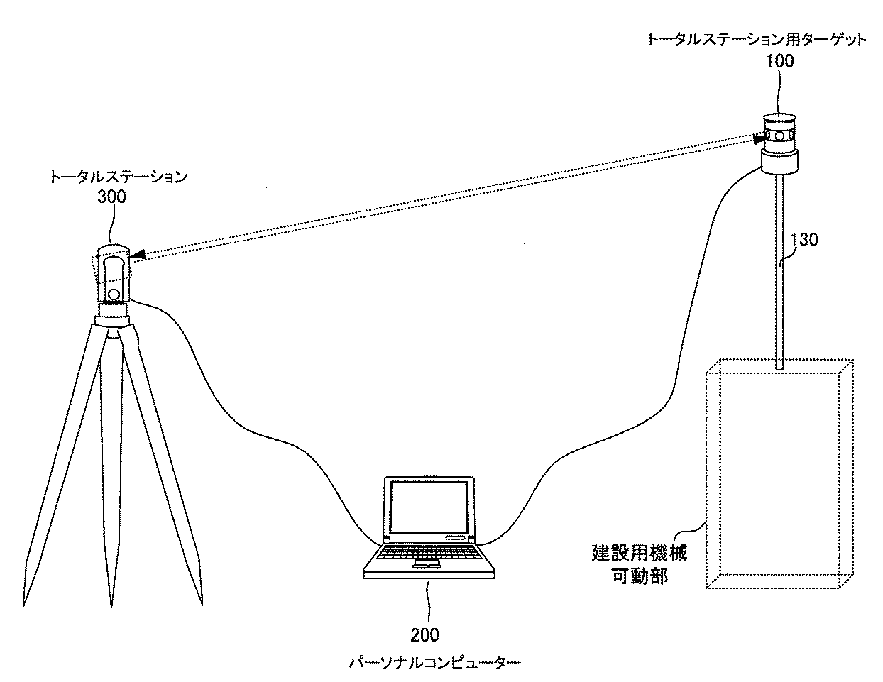
以下、本発明の実施の形態を図面を参照しつつ説明する。本発明の実施の形態に係るトータルステーション用ターゲット100と及びそれを用いた建設用作業機械の制御システ
ム構成の概略を示す図である。図1において、100はトータルステーション用ターゲット、200はこのトータルステーション用ターゲット100及びトータルステーション300とデータ通信可能に接続されたパーソナルコンピュータ、300はトータルステーションをそれぞれ示している。
Hereinafter, embodiments of the present invention will be described with reference to the drawings. It is a figure which shows the outline of the control system structure of the
図1で示すトータルステーション300は、トータルステーション用ターゲット100に向けてパルスレーザ光線を照射し、測定点からのパルス反射光を受光して、各パルス毎に測距を行い、測距結果を平均化して高精度の距離測定を行うものである。また、トータルステーション300は、測距と同時に、パルスレーザ光線の射出方向に係る鉛直角度、水平角度を算出することによって、トータルステーション用ターゲット100における位置座標データを算出することができるようになっている。
The
また、トータルステーション300は、ターゲットを自動追尾して、このターゲットに対して光波を射出するようになっており、例えば、ニコントリンブル社製トータルステーション5600ATSなどを用いることができる。このようなトータルステーション300は一般的に、外部の情報処理装置と接続可能なインターフェイスが設けられている。
The
本発明に係るトータルステーション用ターゲット100及びトータルステーション300と通信可能に接続されるパーソナルコンピュータ200としては現在普及している汎用のものを用いることができる。トータルステーション用ターゲット100及びトータルステーション300とパーソナルコンピュータ200とのデータ通信接続にはRS232Cなどの規格の有線による通信を用いることができるし、また、IEEE802.11b/g/nなどの通信規格の無線通信のいずれも用いることができる。
As the
本発明に係るトータルステーション用ターゲット100は、ポールを介して建設用作業機械の可動部に取り付けられ、トータルステーション300がこれを自動追尾することによってトータルステーション用ターゲット100の位置座標データが求められ、さらにこれから建設用作業機械の可動部の所定位置における位置座標データを算出するようにして用いられる。
The
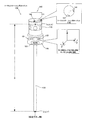
次に、このようなトータルステーション用ターゲット100についてより詳しく説明する。図2は本発明の実施形態に係るトータルステーション用ターゲットの概略を説明する図である。図2は
本発明に係るトータルステーション用ターゲット100は、概略、光学部110及び傾斜センサ部120の2つの機能部から構成されている。トータルステーション用ターゲット100の光学部110には、トータルステーション300から射出されるレーザー光を反射するプリズムなどが設けられており、これによりトータルステーション300はプリズムを目標とし、トータルステーション用ターゲット100を自動追尾することができるようになっている。この光学部110は従来の周知のものを適宜利用することが可能である。
Next, the
一方、本発明に係るトータルステーション用ターゲット100においては、この光学部110と間の相対位置が変化することがないようにして傾斜センサ部120が固定されている。この傾斜センサ部120内に配されている第1傾斜センサ121及び第2傾斜センサ122によって、トータルステーション用ターゲット100が、どの程度傾斜したかに係る情報を取得することができるようになっている。
On the other hand, in the
より具体的には、傾斜センサ部120内には、前記光学部110と間の相対位置が変化することがないように固定されると共に、水平面内におけるx軸の周りの傾き角度(β°)を検出する第1傾斜センサ121と、前記光学部110と間の相対位置が変化すること
がないように固定されると共に、水平面内における前記x軸と直交するy軸の周りの傾き角度(α°)を検出する第2傾斜センサ122とが設けられている。
More specifically, the
なお、本実施形態においては、前記x軸と前記y軸とが直交することを前提としたが、データ処理時における演算等が複雑となることを厭わなければ、x軸とy軸とが直交するように構成することは必須の構成要件とはならない。 In the present embodiment, the x-axis and the y-axis are assumed to be orthogonal to each other. However, the x-axis and the y-axis are orthogonal to each other as long as the calculation during data processing is not complicated. It is not an indispensable component requirement.
また、第1傾斜センサ121によって検出された傾きデータである第1検出情報と、前記第2傾斜センサ122によって検出された傾きデータである第2検出情報とは、傾斜センサ部120内に設けられた出力部123から、外部にデータ出力されるようになっている。出力部123から出力されたデータは、有線又は無線によるデータ通信で、パーソナルコンピュータ200に入力され、パーソナルコンピュータ200において適宜データ処理される。
Further, first detection information that is inclination data detected by the
上記のように構成されるトータルステーション用ターゲット100は、例えば長さDのポール130を介して、建設用作業機械のブレードなどの可動部に取り付けられる。そして、パーソナルコンピュータ200は、トータルステーション300で取得される位置データと、第1傾斜センサ121によって検出された傾き角度データ(第1検出情報)と、前記第2傾斜センサ122によって検出された傾き角度データ(第2検出情報)と、から建設用作業機械の可動部の所定位置を算出するよう構成される。
The
次に、トータルステーション用ターゲット100の変形例について説明する。図3は本発明の他の実施形態に係るトータルステーション用ターゲットの概略を説明する図である。先の図2に示す実施形態に係るトータルステーション用ターゲット100においては、光学部110と傾斜センサ部120とが一体的に設けられていたが、図3に示す他の実施形態に係るトータルステーション用ターゲット100においては、光学部110と傾斜センサ部120とは、ポール130の一部などからなる連結部131によって所定距離保たれて設けられるようになっている。
Next, a modification of the
このような実施形態においても傾斜センサ部120内には、光学部110と間の相対位置が変化することがないように固定されると共に、水平面内におけるx軸の周りの傾き角度(β°)を検出する第1傾斜センサ121と、前記光学部110と間の相対位置が変化することがないように固定されると共に、水平面内における前記x軸と直交するy軸の周りの傾き角度(α°)を検出する第2傾斜センサ122と、第1傾斜センサ121によって検出された傾きデータである第1検出情報と、前記第2傾斜センサ122によって検出された傾きデータである第2検出情報とを外部にデータ出力する出力部123とが設けられることにより、先の実施形態と同様の機能を付与させることができる。
Even in such an embodiment, the
以上のように構成されるトータルステーション用ターゲット100から取得されるデータに基づいて、建設用作業機械の可動部の所定位置を算出する方法を具体的に説明する。以下において、図2に示すように、トータルステーション用ターゲット100が長さDのポール130に取り付けられている場合に基づいて説明する。トータルステーション用ターゲット100における位置座標データ(xo,yo,zo)がトータルステーション30
0で取得され、第1傾斜センサ121によって傾き角度データβ°が、また、第2傾斜センサ122によって傾き角度データα°が検出されたときにおけるポール130先端部における位置座標データ(x’,y’,z’)を算出する方法について説明する。
A method of calculating the predetermined position of the movable part of the construction work machine based on the data acquired from the
The position coordinate data (x ′, y at the tip of the
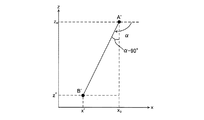
図4は本発明の実施形態に係るトータルステーション用ターゲット100を用いた位置座標データの算出工程を説明する図である。図において、Aはトータルステーション用ターゲット100における位置座標データ(xo,yo,zo)を示しており、Bはポール1
30の先端部における位置座標データ(x’,y’,z’)を示している。
FIG. 4 is a view for explaining the position coordinate data calculation process using the
The position coordinate data (x ′, y ′, z ′) at the tip of 30 is shown.
また、A’−B’はA−Bをxz平面に投影したものを示している。このとき図4(A)に示すように定義されるα°が、第2傾斜センサ122が検出する傾き角度として定義される。また、A’’−B’’はA−Bをyz平面に投影したものを示している。このとき図4(B)に示すように定義されるβ°が、第1傾斜センサ121が検出する傾き角度として定義される。
A'-B 'is a projection of AB on the xz plane. At this time, α ° defined as shown in FIG. 4A is defined as the tilt angle detected by the
図5は直線A−Bのxz平面投影である直線A’−B’を示す図である。当該図から下記(1)式を得ることができる。 FIG. 5 is a diagram illustrating a straight line A′-B ′ that is an xz plane projection of the straight line AB. From the figure, the following equation (1) can be obtained.
サ122が検出する傾き角度α°とから、ポール130の先端部における位置座標データ(x’,y’,z’)を求めることができる。同様にして、ポール130が取り付けられた建設用作業機械における可動部の所定位置の位置座標データについても、パーソナルコンピュータ200によって算出することができる。
次に、以上のようなトータルステーション用ターゲット100を建設用作業機械の可動部に取り付けて該可動部を制御する実施形態について説明する。図7は本発明の実施形態に係るトータルステーション用ターゲット100による検出データに基づいて排土ブレード413を制御する方法を説明する図である。図7においては、建設用作業機械としてブルドーザー400を例にとり、その可動部である排土ブレード413にトータルステーション用ターゲット100を取り付けて、設計データ(仕上げ面高さデータ)に基づいて排土ブレード413の高さを制御する例について説明する。
Next, an embodiment in which the
ブルドーザー400においては、排土ブレード413を有しており、この排土ブレード413がブレード昇降機構部412によって昇降されるように構成されている。ブレード昇降制御部411は通信部410で受信される指令に基づいて、ブレード昇降機構部412に対する制御指令を発するようになっている。
The
パーソナルコンピュータ200は、トータルステーション用ターゲット100からデータ(距離、鉛直角度、水平角度)を取得して、それに基づいてトータルステーション用ターゲット100の位置座標データ位置座標データ(xo,yo,zo)を算出する。一方、
パーソナルコンピュータ200は、トータルステーション用ターゲット100の出力部123から無線通信によりその傾きデータ(α°、β°)を取得して、排土ブレード413の最下部における所定位置の位置座標データ(x’,y’,z’)を算出することができるようになっている。なお、簡単のために、ポール130が延在する方向に排土ブレード413の最下部が存在するものとする。また、ポール130は、排土ブレード413の上部における、排土ブレード413の幅方向略中央付近に取り付けられている。本例では、トータルステーション用ターゲット100から距離Dのところに、排土ブレード413の最下部における(x’,y’,z’)がくるものとする。また、パーソナルコンピュータ200は、仕上げ面高さデータに係る設計データ210をその記憶手段に有しており、これを参照することができるようになっている。また、パーソナルコンピュータ200からは、ブルドーザー400の通信部410に対して制御指令を送信可能に構成されている。
The
The
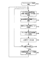
以上のような構成に基づくブルドーザー400の排土ブレード413の昇降制御のための処理について説明する。図8は本発明の実施形態に係るトータルステーション用ターゲ
ット100による排土ブレード413の制御フローチャートの一例を示す図である。このような制御フローチャートは例えばパーソナルコンピュータ200において実行される。
Processing for raising and lowering the
図8において、ステップS100で、パーソナルコンピュータ200による処理が開始されると、続いて、ステップS101で、トータルステーション300から、トータルステーション用ターゲット100の位置測定情報(距離、鉛直角度、水平角度)を取得する。そして、次に、ステップS102で、取得された距離、鉛直角度、水平角度から直交座標系(xo,yo,zo)位置情報を演算する。
In FIG. 8, when the processing by the
続いて、ステップS103において、トータルステーション用ターゲット100から第1傾斜センサ121及び第2傾斜センサ122の傾き角度情報(α°、β°))を受信する。続いて、ステップS104において、ブレード最下部の位置情報(x’,y’,z’)を算出する。なお、この算出のためには、図4乃至図6に関連して説明した算出方法が用いられる。ステップS105では、ステップS104で算出されたz’と、仕上げ面の高さとして定義される設計データ210との比較を行う。
Subsequently, in step S103, the tilt angle information (α °, β °) of the
ステップS106においては、ステップS106における比較結果の乖離が所定値以上であるか否かが判定される。ステップS106における判定結果がNOである場合には、再びステップS101に戻りループする。一方、判定結果がYESである場合には、ステップS107に進み、ブルドーザー400の通信部410に対して、ブレードの昇降動作に関する制御指令を送信する。
In step S106, it is determined whether or not the difference between the comparison results in step S106 is a predetermined value or more. If the determination result in step S106 is NO, the process returns to step S101 and loops again. On the other hand, if the determination result is YES, the process proceeds to step S107, and a control command related to the lifting / lowering operation of the blade is transmitted to the
以上のように、本発明のトータルステーション用ターゲット100及びそれを用いた建設用作業機械(ブルドーザー400)の制御方法によれば、トータルステーション用ターゲット100の傾斜を考慮した精度の高い水平座標位置データを求めることが可能となる。また、このようなデータに基づいて建設用作業機械の可動部(排土ブレード413)を制御するので、精度の高い制御を行うことができるようになる。
As described above, according to the control method of the
次に本発明の他の実施形態について説明する。図9は本発明の他の実施形態に係るトータルステーション用ターゲットの概略を説明する図である。図9に示す実施形態は、トータルステーション用ターゲット100頂部の天面において、取り付け位置決め用目印が設けられている点で、先の実施形態と相違するものである。図9において、図2と同様の符号が付されている構成については、先の実施形態と同様のものであるので説明を省略する。
Next, another embodiment of the present invention will be described. FIG. 9 is a diagram for explaining the outline of a total station target according to another embodiment of the present invention. The embodiment shown in FIG. 9 is different from the previous embodiment in that an attachment positioning mark is provided on the top surface of the top of the
これまで説明してきたように、第1傾斜センサ121はx軸の周りの傾き角度(β°)を検出し、第2傾斜センサ122はy軸の周りの傾き角度(α°)を検出するが、上記のようなx軸と、y軸とを把握した上で、トータルステーション用ターゲット100を建設用作業機械の可動部に取り付けることができれば、建設用作業機械の可動部における所定位置の算出を行いやすい。そこで、本実施形態では、トータルステーション用ターゲット100の天面において、取り付け位置決め用目印140を設けて、x軸とy軸とを目視によって把握可能に構成している。
As described above, the
取り付け位置決め用目印140は、2つの取り付け位置決め用の照準線である第1位置決め用目印141及び第2位置決め用目印142からなっている。第1位置決め用目印141は第1傾斜センサ121が傾きを検出するときに基準とするx軸の方向を示し、第2位置決め用目印142は第2傾斜センサ122が傾きを検出するときに基準とするy軸の方向を示している。
The
以上のような第1位置決め用目印141及び第2位置決め用目印142からなる取り付
け位置決め用目印140が設けられたトータルステーション用ターゲット100によれば、建設用作業機械の可動部における第1の所定位置と、さらにこれとは異なる第2の所定位置を算出することが容易となる。このことを建設用作業機械としてブルドーザー400を例にとり、その可動部である排土ブレード413にトータルステーション用ターゲット100を取り付ける場合で説明する。なお、以下、図7に示すブルドーザー400と同じものを例にとり説明する。
According to the
図10は、図9に示す他の実施形態に係るトータルステーション用ターゲット100の排土ブレード413への適用例を説明する図である。図10に示す適用例においては、トータルステーション用ターゲット100を排土ブレード413に取り付ける際には、第1位置決め用目印141及び第2位置決め用目印142を参照して、排土ブレード413の幅方向がx軸方向と同方向となるように、また、ブルドーザー400の進行方向がy軸方向と同方向となるようにして取り付ける。さらに、ポール130は、排土ブレード413の上部における、排土ブレード413の幅方向の一方端付近に取り付けられている。これにより、
上記のような適用例によれば、トータルステーション用ターゲット100から距離Dのところにある、排土ブレード413の最下部(x’,y’,z’)が、これまで説明した方法と同様の方法により算出可能であると共に、(x’,y’,z’)から排土ブレード413の幅方向にW移動した点(x’’,y’’,z’’)を第2傾斜センサ122で検出される傾き角度(α°)に基づいて容易に算出することができる。
FIG. 10 is a diagram for explaining an application example of the
According to the application example as described above, the lowermost part (x ′, y ′, z ′) of the
以上のような実施形態によれば、建設用作業機械の可動部における第1の所定位置と、さらにこれとは異なる第2の所定位置を算出することが容易となり、第1の所定位置及び第2の所定位置の2つの位置に基づいて、建設用作業機械の可動部を制御することで、より精度の高い制御を行うことができるようになる。 According to the embodiment as described above, it is easy to calculate the first predetermined position in the movable part of the construction work machine and the second predetermined position different from the first predetermined position. By controlling the movable part of the construction work machine based on the two predetermined positions, more accurate control can be performed.
次に、本発明に係るトータルステーション用ターゲット100を他の建設用作業機械の可動部に取り付けて該可動部を制御する他の実施形態について説明する。図11は本発明の実施形態に係るトータルステーション用ターゲット100による検出データに基づいてスクリード550を制御する方法を説明する図であり、また、図12はトータルステーション用ターゲット100を用いたスクリード550制御システムのブロック構成の概略を示す図である。また、図11及び図12においては、建設用作業機械としてスリップフォームぺーバー500を例にとり、その可動部であるスクリード550にトータルステーション用ターゲット100を2基取り付けて、設計データ(仕上げ面高さデータ)に基づいてスクリード550の高さを制御する例について説明する。
Next, another embodiment in which the
図11及び図12において、500はスリップフォームぺーバー、501は主制御部、502は通信部、510は右前クローラー走行部、511は右前昇降制御部、512は右前昇降機構部、515は右前連結部、520は左前クローラー走行部、521は左前昇降制御部、522は左前昇降機構部、525は左前連結部、530は右後クローラー走行部、531は右後昇降制御部、532は右後昇降機構部、535は右後連結部、540は左後クローラー走行部、541は左後昇降制御部、542は左後昇降機構部、545は左後連結部、550はスクリードをそれぞれ示している。
11 and 12, 500 is a slip foam paver, 501 is a main control unit, 502 is a communication unit, 510 is a front right crawler running unit, 511 is a front right elevating control unit, 512 is a front right elevating mechanism unit, and 515 is a front right connection. 520 is a left front crawler traveling unit, 521 is a left front lifting control unit, 522 is a left front lifting mechanism unit, 525 is a left front connecting unit, 530 is a right rear crawler traveling unit, 531 is a right rear lifting control unit, and 532 is a right rear lifting unit. The
図11に示すようなスリップフォームぺーバー500は、滑走路や道路のような、同一断面の連続した舗装構造物を構築するために、コンクリート等の舗装材を所定の形状に成形するスリップフォーム工法で用いられるものである。このスリップフォーム工法では、ダンプ等の運搬車両から供給された舗装材を、スリップフォームペーバ500を使用して、舗装材を敷き均し、所定の断面形状に成形する。
A
このスリップフォーム工法に使用されるスリップフォームペーバ500は、前後左右に設けられた自走式の台車であるクローラー走行部510、520、530、540と、これらクローラー走行部と連結部515、525、535、545によって連結され、所定の断面形状に舗装材を敷き均すスクリード550と、を有して構成されている。
The
それぞれのクローラー走行部510、520、530、540には、速度vを制御するための速度制御機構部と、それぞれのクローラー走行部の操舵角θfr、θfl、θrr、θrlを制御するための操舵角制御機構部、及び、前記連結部515、525、535、545の高さhfr、hfl、hrr、hrlを制御するための昇降機構部512、522、532、542が設けられている。
Each
スリップフォーム工法においては、スクリード550の高さにより仕上げ面の高さが決定されるが、スクリード550の高さは、昇降機構部512、522、532、542によって高さhfr、hfl、hrr、hrlが調整されることによって決めることができる。
In the slip form method, the height of the finished surface is determined by the height of the
そこで、上記のような昇降機構部512、522、532、542に対する高さ制御の指令値を算出するために、本実施形態においては、スリップフォームぺーバー500(建設用作業機械)の可動部であるスクリード550の位置をトータルステーション用ターゲット100により把握するようにしている。より具体的には、スリップフォームぺーバー500の長手方向両端部それぞれに本発明に係るトータルステーション用ターゲット100r、100lを図示するように設ける。ここで、スクリード550で均そうとする道路などの幅員方向に傾斜が存在しないような場合においても、トータルステーション用ターゲット100を1基のみ設けるようにするのではなく、スクリード550の両端にトータルステーション用ターゲット100を2基設けることが重要である。なぜならば、スクリード550にはたわみやねじれが生じるので、1基のトータルステーション用ターゲット100でスクリード550の底面部の高さを算出すると、所定の精度を得ることができないからである。
Therefore, in order to calculate the height control command value for the
トータルステーション用ターゲット100rの位置座標(x1,y1,z1)に係るデー
タを得るために、トータルステーション用ターゲット100rを自動追尾するトータルステーション300rが、また、トータルステーション用ターゲット100lの位置座標(x2,y2,z2)に係るデータを得るために、トータルステーション用ターゲット100
lを自動追尾するトータルステーション300lが設けられ、トータルステーション300r、300lで取得されたデータ(距離、鉛直角度、水平角度)は、パーソナルコンピュータ200に入力され、先の2つの位置座標が演算される。
In order to obtain data related to the position coordinates (x 1 , y 1 , z 1 ) of the
A total station 300l that automatically tracks 1 is provided, and data (distance, vertical angle, horizontal angle) acquired by the
さらに、パーソナルコンピュータ200は、トータルステーション用ターゲット100r、100lの各出力部から無線通信によりそれぞれの傾きデータ(αr°、βr°及びαl°、βl°)を取得して、スクリード550の両端部における最下部置の位置座標データ(x1’,y1’,z1’)及び(x2’,y2’,z2’)を算出することができるようになっている。
Furthermore, the
なお、本例では、トータルステーション用ターゲット100rから鉛直下方に向け距離D1のところに、スクリード550の位置座標(x1’,y1’,z1’)が、また、トータルステーション用ターゲット100lから鉛直下方に向け距離D2のところに、スクリー
ド550の最下部の位置座標(x2’,y2’,z2’)が配されるように設定されている
。これにより、式(1)乃至式(7)で説明した算出方法を適用することにより、(x1
’,y1’,z1’)及び(x2’,y2’,z2’)を算出することができる。
In this example, the position coordinates (x 1 ′, y 1 ′, z 1 ′) of the
', Y 1 ', z 1 ') and (x 2 ', y 2 ', z 2 ') can be calculated.
パーソナルコンピュータ200は、スクリード550で均す仕上げ面の高さデータに係
る設計データ210をその記憶手段に有しており、これを参照することができるようになっている。また、パーソナルコンピュータ200からは、スリップフォームぺーバー500の通信部502に対して制御指令を送信可能に構成されている。
The
スリップフォームぺーバー500においては、連結部515、525、535、545の高さhfr、hfl、hrr、hrlを調整する昇降機構部512、522、532、54に対して、昇降制御部511、521、531、531が制御指令を行うようになっており、この制御指令は主制御部501から送信される。主制御部501に対する指令は、通信部502を介して、パーソナルコンピュータ200から受信することができるようになっている。
In the
以上のような構成に基づくスリップフォームぺーバー500のスクリード550の昇降制御のための処理について説明する。図13は本発明の実施形態に係るトータルステーション用ターゲット100によるスクリード550の制御フローチャートの一例を示す図である。このような制御フローチャートは例えばパーソナルコンピュータ200において実行される。
Processing for raising and lowering the
ステップS200で、パーソナルコンピュータ200による処理が開始されると、続いて、ステップS201において、トータルステーション300r、300lから、それぞれが自動追尾しているトータルステーション用ターゲット100r、100lの位置測定情報(距離、鉛直角度、水平角度)を取得する。
When processing by the
ステップS202では、トータルステーション300r、300lから取得された距離、鉛直角度、水平角度に基づいて、それぞれのターゲットの直交座標系位置情報(x1,
y1,z1)及び(x2,y2,z2)を演算する。
In step S202, based on the distance, vertical angle, and horizontal angle acquired from the
y 1 , z 1 ) and (x 2 , y 2 , z 2 ) are calculated.
ステップS203においては、左右のトータルステーション用ターゲット100r、100lから、それぞれの傾斜センサ部120における第1傾斜センサ121、第2傾斜センサ122で検出された傾斜センサ検出情報(αr,βr)及び(αl,βl)を受信する。
In step S203, the inclination sensor detection information (α r , β r ) detected by the
ステップS204では、トータルステーション300rの位置座標(x1,y1,z1)
と傾斜センサ検出情報(αr,βr)とからスクリード550の右端下部の位置情報(x1
’,y1’,z1’)を算出し、トータルステーション300lの位置座標(x2,y2,z2)と傾斜センサ検出情報(αl,βl)とからスクリード550の左端下部の位置情報(
x2’,y2’,z2’)を算出する。このときの算出方法は、これまでに説明したものを
用いることができる。
In step S204, the position coordinates (x 1 , y 1 , z 1 ) of the
And tilt sensor detection information (α r , β r ), position information (x 1
', Y 1 ', z 1 '), and the position of the lower left end of the
x 2 ', y 2 ', z 2 ') is calculated. As the calculation method at this time, the one described so far can be used.
ステップS205では、ステップS204で算出されたz1’及びz2’を、仕上げ面の高さとして規定されている設計データ210との比較を行う。
In step S205, z 1 ′ and z 2 ′ calculated in step S204 are compared with
ステップS206では、ステップS205の比較に基づいて各昇降部の目標高さ(hfr,hfl,hrr,hrl)を演算し、ステップS207で、スリップフォームぺーバー500の通信部502に対し、昇降部制御指令を送信する。
In step S206, the target height (h fr , h fl , h rr , h rl ) of each lifting unit is calculated based on the comparison in step S205, and in step S207, the
以上、本発明のトータルステーション用ターゲット100及びそれを用いた建設用作業機械(スリップフォームぺーバー500)の制御方法によれば、トータルステーション用ターゲット100の傾斜を考慮した精度の高い水平座標位置データを求めることが可能となる。また、このようなデータに基づいて建設用作業機械の可動部(スクリード550)を制御するので、精度の高い制御を行うことができるようになる。
As described above, according to the control method for the
次に、本発明に係るトータルステーション用ターゲット100を他の建設用作業機械の可動部に取り付けて該可動部を制御する他の実施形態について説明する。図14は本発明の実施形態に係るトータルステーション用ターゲットをスリップフォーム装置に適用した例を説明する図である。
Next, another embodiment in which the
図14に示すスリップフォーム装置600において、先の図11に示す実施形態と同様の参照番号が付された構成につては同様のものであるので説明を省略する。本実施形態におけるスリップフォーム装置600では、先のスクリード550に代えて、中央連結部605が設けられている。そして、この中央連結部605から延在する側方連結部610の先端部に、型枠(スリップフォーム)620が設けられる構成となっている。このようなスリップフォーム装置600によれば、型枠(スリップフォーム)620に対して、不図示の注入装置により、コンクリートが矢印Cのごとく注入されつつ、さらに、クローラー走行部510、520、530、540によって型枠(スリップフォーム)620が移動されることで、連続的なコンクリート成形物を施工することが可能となる。
In the
上記のようなスリップフォーム装置600を用いたスリップフォーム工法においては、型枠(スリップフォーム)620の高さにより仕上げ面の高さが決定されるが、型枠(スリップフォーム)620の高さは、昇降機構部512、522、532、542によって高さhfr、hfl、hrr、hrlが調整されることによって決められる。
In the slip foam method using the
上記のような昇降機構部512、522、532、542に対する高さ制御の指令値を算出するために、本実施形態においては、スリップフォーム装置600における型枠(スリップフォーム)620の前後に、トータルステーション用ターゲット100f、100rを取り付けることで、型枠(スリップフォーム)620の位置を把握するようにしている。
In order to calculate the height control command value for the
また、本実施形態においては、トータルステーション用ターゲット100fの位置座標(xf,yf,zf)に係るデータを得るために、トータルステーション用ターゲット10
0fを自動追尾するトータルステーション300fが、また、トータルステーション用ターゲット100rの位置座標(xr,yr,zr)に係るデータを得るために、トータルス
テーション用ターゲット100rを自動追尾するトータルステーション300rが設けられ、トータルステーション300r、300lで取得されたデータ(距離、鉛直角度、水平角度)は、パーソナルコンピュータ200に入力され、2つの位置座標(xf’,yf’,zf’)、(xr’,yr’,zr’)が演算される。演算の方法については、これまで説明した方法と同様のものを用いるようにするため細かい説明は省略する。
In this embodiment, in order to obtain data related to the position coordinates (x f , y f , z f ) of the total station target 100f, the total station target 10f is obtained.
A
以上、本発明のトータルステーション用ターゲット及びそれを用いた建設用作業機械の制御方法によれば、傾斜センサに基づく傾斜情報を考慮した、精度の高い水平座標位置データを求めることが可能となるので、このようなデータに基づいて建設用作業機械の可動部を制御すると、精度の高い制御を行うことができるようになる。 As described above, according to the total station target of the present invention and the construction work machine control method using the target, it is possible to obtain highly accurate horizontal coordinate position data in consideration of the tilt information based on the tilt sensor. If the movable part of the construction work machine is controlled based on such data, highly accurate control can be performed.
100、100r、100l、100f、100r・・・トータルステーション用ターゲット
110・・・光学部
120・・・傾斜センサ部
121・・・第1傾斜センサ
122・・・第2傾斜センサ
123・・・出力部
130・・・ポール
131・・・連結部
140・・・取り付け位置決め用目印
141・・・第1位置決め用目印
142・・・第2位置決め用目印
200・・・パーソナルコンピュータ
210・・・設計データ
300、300r、300l・・・トータルステーション
400・・・ブルドーザー(建設用作業機械)
410・・・通信部
411・・・ブレード昇降制御部
412・・・ブレード昇降機構部
413・・・排土ブレード(可動部)
500・・・スリップフォームぺーバー(建設用作業機械)
501・・・主制御部
502・・・通信部
510・・・右前クローラー走行部
511・・・右前昇降制御部
512・・・右前昇降機構部
515・・・右前連結部
520・・・左前クローラー走行部
521・・・左前昇降制御部
522・・・左前昇降機構部
525・・・左前連結部
530・・・右後クローラー走行部
531・・・右後昇降制御部
532・・・右後昇降機構部
535・・・右後連結部
540・・・左後クローラー走行部
541・・・左後昇降制御部
542・・・左後昇降機構部
545・・・左後連結部
550・・・スクリード(可動部)
600・・・スリップフォーム装置
605・・・中央連結部
610・・・側方連結部
620・・・型枠(スリップフォーム)
100, 100r, 100l, 100f, 100r ...
410 ...
500 ・ ・ ・ Slip foam paper (construction machine)
501 ...
600 ...
Claims (2)
前記光学部と間の相対位置が変化することがないように固定されると共に、水平面内における第1の軸の周りの傾きを検出する第1の傾斜センサと、
前記光学部と間の相対位置が変化することがないように固定されると共に、水平面内における前記第1の軸と直交する第2の軸の周りの傾きを検出する第2の傾斜センサと、
前記第1の傾斜センサが傾きを検出するときに基準とする軸の方向を示す第1位置決め用目印と、前記第2の傾斜センサが傾きを検出するときに基準とする軸の方向を示す第2位置決め用目印と、を有する天面と、
前記第1の傾斜センサによって検出された第1検出情報と、前記第2の傾斜センサによって検出された第2検出情報とを出力する出力部と、を有することを特徴とするトータルステーション用ターゲット。 An optical unit that reflects the laser light emitted from the total station;
A first inclination sensor that is fixed so that a relative position between the optical part and the optical unit does not change, and that detects an inclination around a first axis in a horizontal plane;
A second inclination sensor that is fixed so as not to change a relative position with the optical unit and detects an inclination around a second axis that is orthogonal to the first axis in a horizontal plane;
A first positioning mark indicating the direction of the axis used as a reference when the first tilt sensor detects the tilt, and a first mark indicating the direction of the axis used as the reference when the second tilt sensor detects the tilt. 2 a top surface having positioning marks;
A total station target, comprising: an output unit that outputs first detection information detected by the first tilt sensor and second detection information detected by the second tilt sensor.
前記光学部と間の相対位置が変化することがないように固定されると共に、水平面内における第1の軸の周りの傾きを検出する第1の傾斜センサと、
前記光学部と間の相対位置が変化することがないように固定されると共に、水平面内における前記第1の軸と直交する第2の軸の周りの傾きを検出する第2の傾斜センサと、
前記第1の傾斜センサが傾きを検出するときに基準とする軸の方向を示す第1位置決め用目印と、前記第2の傾斜センサが傾きを検出するときに基準とする軸の方向を示す第2位置決め用目印と、を有する天面と、
前記第1の傾斜センサによって検出された第1検出情報と、前記第2の傾斜センサによって検出された第2検出情報とを出力する出力部と、を有するトータルステーション用ターゲットを、建設用作業機械の可動部に装着し、
トータルステーションによって前記トータルステーション用ターゲットの自動追尾を行い、前記前記トータルステーション用ターゲットの位置情報を取得し、
前記トータルステーション用ターゲットの前記出力部から出力される前記第1検出情報と前記第2検出情報を取得し、
前記位置情報と前前記第1検出情報と前記第2検出情報とから前記可動部における所定箇所の位置座標を算出し、
算出された前記位置座標に基づいて前記可動部の位置制御を行うことを特徴とするトータルステーション用ターゲットを用いた建設用作業機械の制御方法。 An optical unit that reflects the laser light emitted from the total station;
A first inclination sensor that is fixed so that a relative position between the optical part and the optical unit does not change, and that detects an inclination around a first axis in a horizontal plane;
A second inclination sensor that is fixed so as not to change a relative position with the optical unit and detects an inclination around a second axis that is orthogonal to the first axis in a horizontal plane;
A first positioning mark indicating the direction of the axis used as a reference when the first tilt sensor detects the tilt, and a first mark indicating the direction of the axis used as the reference when the second tilt sensor detects the tilt. 2 a top surface having positioning marks;
A total station target having an output unit for outputting first detection information detected by the first tilt sensor and second detection information detected by the second tilt sensor is used for a construction work machine. Attach to moving parts,
It performs automatic tracking of the target for the total station by total station, to obtain position information of the target for said total station,
Obtaining the first detection information and the second detection information output from the output unit of the total station target;
From the position information, the previous first detection information, and the second detection information, a position coordinate of a predetermined location in the movable part is calculated,
A method of controlling a construction work machine using a target for a total station, wherein the position of the movable portion is controlled based on the calculated position coordinates.
Priority Applications (1)
| Application Number | Priority Date | Filing Date | Title |
|---|---|---|---|
| JP2010118919A JP5583477B2 (en) | 2010-05-25 | 2010-05-25 | Total station target and construction machine control method using the same |
Applications Claiming Priority (1)
| Application Number | Priority Date | Filing Date | Title |
|---|---|---|---|
| JP2010118919A JP5583477B2 (en) | 2010-05-25 | 2010-05-25 | Total station target and construction machine control method using the same |
Publications (2)
| Publication Number | Publication Date |
|---|---|
| JP2011247652A JP2011247652A (en) | 2011-12-08 |
| JP5583477B2 true JP5583477B2 (en) | 2014-09-03 |
Family
ID=45413103
Family Applications (1)
| Application Number | Title | Priority Date | Filing Date |
|---|---|---|---|
| JP2010118919A Active JP5583477B2 (en) | 2010-05-25 | 2010-05-25 | Total station target and construction machine control method using the same |
Country Status (1)
| Country | Link |
|---|---|
| JP (1) | JP5583477B2 (en) |
Families Citing this family (12)
| Publication number | Priority date | Publication date | Assignee | Title |
|---|---|---|---|---|
| CN102768026B (en) * | 2012-07-23 | 2015-07-29 | 黑龙江科技大学 | The equipment of the full-scale quick detection of a kind of blade |
| US8989968B2 (en) * | 2012-10-12 | 2015-03-24 | Wirtgen Gmbh | Self-propelled civil engineering machine system with field rover |
| JP2014102118A (en) * | 2012-11-19 | 2014-06-05 | Tamagawa Seiki Co Ltd | Position specifying system and piling position specifying method using the same |
| JP2016045002A (en) * | 2014-08-20 | 2016-04-04 | 株式会社トプコン | Illuminance measuring system |
| JP6307475B2 (en) | 2015-07-21 | 2018-04-04 | 株式会社トプコン | Illuminance measurement system |
| JP2017078688A (en) * | 2015-10-22 | 2017-04-27 | 株式会社トプコン | Measuring device, measuring method, and program for measurement |
| JP7029934B2 (en) * | 2017-11-06 | 2022-03-04 | 前田道路株式会社 | Mounting jig |
| JP7184998B2 (en) * | 2017-11-06 | 2022-12-06 | 前田道路株式会社 | Mounting jig |
| JP7292831B2 (en) * | 2018-07-13 | 2023-06-19 | 株式会社トプコン | Target device and survey system |
| JP6975114B2 (en) * | 2018-09-21 | 2021-12-01 | 株式会社日立建機ティエラ | Construction machinery |
| JP7191736B2 (en) * | 2019-03-11 | 2022-12-19 | 株式会社トプコン | Asphalt finisher and screed control method |
| US12006656B2 (en) | 2019-03-29 | 2024-06-11 | Komatsu Ltd. | Work vehicle, control device for work vehicle, and method for specifying direction of work vehicle |
Family Cites Families (5)
| Publication number | Priority date | Publication date | Assignee | Title |
|---|---|---|---|---|
| JP3541960B2 (en) * | 1993-12-24 | 2004-07-14 | 独立行政法人土木研究所 | Automatic 3D position control method for construction machinery |
| JPH0843093A (en) * | 1994-08-03 | 1996-02-16 | Nishimatsu Constr Co Ltd | Method for measuring position of completed part of construction and heavy machine during construction |
| US5771978A (en) * | 1996-06-05 | 1998-06-30 | Kabushiki Kaisha Topcon | Grading implement elevation controller with tracking station and reference laser beam |
| JP2001241950A (en) * | 2000-03-02 | 2001-09-07 | Topcon Corp | Target and surveying device and method |
| JP3119253U (en) * | 2005-12-06 | 2006-02-16 | 有限会社画像計測研究所 | Photo measurement target, target application tool, and photo measurement method |
-
2010
- 2010-05-25 JP JP2010118919A patent/JP5583477B2/en active Active
Also Published As
| Publication number | Publication date |
|---|---|
| JP2011247652A (en) | 2011-12-08 |
Similar Documents
| Publication | Publication Date | Title |
|---|---|---|
| JP5583477B2 (en) | Total station target and construction machine control method using the same | |
| CN109958036B (en) | Self-propelled construction machine and method for controlling a self-propelled construction machine | |
| US11313679B2 (en) | Self-propelled civil engineering machine system with field rover | |
| JP5055137B2 (en) | Construction machine control method and control system | |
| CN102220738B (en) | Paving machine control device and method | |
| EP2984233B1 (en) | Automatic track alignment control kit and method for automated track alignment | |
| JP5602452B2 (en) | Construction method of asphalt finisher and asphalt pavement | |
| AU2005315566A1 (en) | Method and device for monitoring a road processing machine | |
| JP2001262611A (en) | Method of controlling self-propelled type construction machinery on designed route | |
| US10895112B2 (en) | Slope compensation system for rotary drill machines | |
| AU2018416541B2 (en) | Control system and method for work machine, and work machine | |
| US12043964B2 (en) | Method of tamping a track in the area for a switch | |
| CN105780634B (en) | Paving thickness measuring system, method and paver | |
| CN115247393B (en) | System and method for controlling road construction process | |
| CN220132708U (en) | Construction machine | |
| US20230383486A1 (en) | Self-propelled ground-processing machine and method for controlling a self-propelled ground-processing machine, as well as method for processing the ground with one or more self-propelled ground-processing machines | |
| US20230175236A1 (en) | Work machine with grade control using external field of view system and method | |
| JP2022154088A (en) | screed controller | |
| JPH04272303A (en) | Operation of leveling machine | |
| JP2000046550A (en) | Tracking/measuring device movement carriage for automatic tracking/measuring system |
Legal Events
| Date | Code | Title | Description |
|---|---|---|---|
| A621 | Written request for application examination |
Free format text: JAPANESE INTERMEDIATE CODE: A621 Effective date: 20120913 |
|
| A977 | Report on retrieval |
Free format text: JAPANESE INTERMEDIATE CODE: A971007 Effective date: 20130808 |
|
| A131 | Notification of reasons for refusal |
Free format text: JAPANESE INTERMEDIATE CODE: A131 Effective date: 20130814 |
|
| A521 | Request for written amendment filed |
Free format text: JAPANESE INTERMEDIATE CODE: A523 Effective date: 20130927 |
|
| TRDD | Decision of grant or rejection written | ||
| A01 | Written decision to grant a patent or to grant a registration (utility model) |
Free format text: JAPANESE INTERMEDIATE CODE: A01 Effective date: 20140709 |
|
| A61 | First payment of annual fees (during grant procedure) |
Free format text: JAPANESE INTERMEDIATE CODE: A61 Effective date: 20140716 |
|
| R150 | Certificate of patent or registration of utility model |
Ref document number: 5583477 Country of ref document: JP Free format text: JAPANESE INTERMEDIATE CODE: R150 |
|
| S531 | Written request for registration of change of domicile |
Free format text: JAPANESE INTERMEDIATE CODE: R313531 |
|
| R350 | Written notification of registration of transfer |
Free format text: JAPANESE INTERMEDIATE CODE: R350 |
|
| R250 | Receipt of annual fees |
Free format text: JAPANESE INTERMEDIATE CODE: R250 |
|
| R250 | Receipt of annual fees |
Free format text: JAPANESE INTERMEDIATE CODE: R250 |
|
| R250 | Receipt of annual fees |
Free format text: JAPANESE INTERMEDIATE CODE: R250 |
|
| R250 | Receipt of annual fees |
Free format text: JAPANESE INTERMEDIATE CODE: R250 |
|
| R250 | Receipt of annual fees |
Free format text: JAPANESE INTERMEDIATE CODE: R250 |
|
| R250 | Receipt of annual fees |
Free format text: JAPANESE INTERMEDIATE CODE: R250 |
|
| R250 | Receipt of annual fees |
Free format text: JAPANESE INTERMEDIATE CODE: R250 |
|
| R250 | Receipt of annual fees |
Free format text: JAPANESE INTERMEDIATE CODE: R250 |