JP5582922B2 - Image blur correction apparatus and imaging apparatus - Google Patents
Image blur correction apparatus and imaging apparatus Download PDFInfo
- Publication number
- JP5582922B2 JP5582922B2 JP2010187475A JP2010187475A JP5582922B2 JP 5582922 B2 JP5582922 B2 JP 5582922B2 JP 2010187475 A JP2010187475 A JP 2010187475A JP 2010187475 A JP2010187475 A JP 2010187475A JP 5582922 B2 JP5582922 B2 JP 5582922B2
- Authority
- JP
- Japan
- Prior art keywords
- coil
- magnet
- image blur
- side direction
- blur correction
- Prior art date
- Legal status (The legal status is an assumption and is not a legal conclusion. Google has not performed a legal analysis and makes no representation as to the accuracy of the status listed.)
- Active
Links
Images


Description
本発明は、レンズ鏡筒等において像ブレ補正をする像ブレ補正装置、及び像ブレ補正装置を備えた撮像装置に関する。 The present invention relates to an image blur correction device that performs image blur correction in a lens barrel and the like, and an imaging device including the image blur correction device.
従来から、手持ち撮影時等で生じ易い手振れ等による像ブレを防止する像ブレ補正装置が知られており、カメラ本体に加わる振れを検出し、その検出結果に応じて補正レンズを光軸に直交する方向に移動させる構成を有する。補正レンズは撮影レンズ系の一部をなし、コイルとマグネットを組み合わせ、コイル電流によって発生するローレンツ力で可動部を駆動するボイスコイルモータ型アクチュエータで、光軸に対して直交する面内にて振れを吸収する方向に移動する。これによって振れによる結像位置のずれを補正することにより、像ブレが解消する。 Conventionally, there has been known an image blur correction device that prevents image blur due to camera shake or the like that is likely to occur during hand-held shooting, etc., and detects the shake applied to the camera body, and the correction lens is orthogonal to the optical axis according to the detection result. It has the structure which moves to the direction to do. The correction lens is a part of the photographic lens system, and is a voice coil motor type actuator that combines the coil and magnet and drives the moving part with the Lorentz force generated by the coil current. Move in the direction of absorbing. As a result, the image blur is eliminated by correcting the shift of the imaging position due to the shake.
図13に従来の像ブレ補正機構の例を示す。固定部材であるベース151にはコイル152aが固定されている。また、補正レンズ113を保持するレンズホルダ155は、ベース151に対する可動部であり、マグネット155aを備える。図中にA、Bの矢印で示す方向は、図13の紙面内で直交する2軸の駆動方向をそれぞれ示しており、マグネット155aはN及びSで示すように、着磁方向がB方向に沿っている。dは各方向におけるレンズホルダ155の可動量(最大変位量)を表す。光軸方向から見て、コイル152aの長辺方向の直線部長をL1とし、コイル152aの短辺方向の外形長をL2とする。直方体形状のマグネット155aについては、コイル152aの長辺方向に平行な方向における外形長をXとし、コイル152aの長辺方向と垂直な方向(駆動力の発生方向)における外形長をYとする。図13から分かるように、「X>Y」であり、レンズホルダ155が可動量dだけ動いたときでも、マグネット155aはコイル152aの直線部よりも外側(A方向)の範囲まで覆うように配置されている。
コイル152aに電流を流すと、マグネット155aの着磁境界に対して略直交するB方向において、コイル152とマグネット155aにローレンツ力が発生し、可動部は光軸と直交する方向に移動する。このようなムービングマグネット型アクチュエータを、光軸回りに90°の角度間隔をもって2個配置すれば、両者の駆動力が合成されるので、レンズホルダ155を光軸と直交する面内で自在に移動させることができる。
FIG. 13 shows an example of a conventional image blur correction mechanism. A
When a current is passed through the
上記のようなボイスコイルモータにおいてマグネットを小型化する技術として、特許文献1に像ブレ補正装置が開示されている。この装置はマグネットが肉厚部と肉薄部を有し、肉厚部をコイルに対向させ、肉薄部を磁気検出センサに対向させた構成をもつ。
As a technique for reducing the size of the magnet in the voice coil motor as described above,
従来の装置は、可動部の制御性について以下の問題がある。
図13に示した従来の機構では、マグネット155aがコイル152aの直線部(L1参照)から外れてコイル152aの曲線部にかかるとローレンツ力の方向が乱れ、所望の方向の力が得にくくなる。その結果、駆動制御が不安定になる可能性がある。より大きな像ブレ量を補正しようとする場合、可動部の移動量をより大きく設定する必要がある。このため、コイルを大型化させなければ制御性を高めるのに限界があるが、像ブレ補正装置の大型化が懸念される。
また、特許文献1に開示の像ブレ補正装置では、マグネットの厚み方向の小型化を実現している。しかし、より大きな像ブレ量を補正しようとする場合、コイルと対向する面積は大きくしなければならないと考えられる。
本発明は、マグネット及びコイルにより構成されたアクチュエータを用いた像ブレ補正装置において、可動部の移動量をより大きく設定した場合でも、像ブレ補正装置の大型化を抑えつつ可動部の制御性を維持することを目的とする。
The conventional apparatus has the following problems regarding the controllability of the movable part.
In the conventional mechanism shown in FIG. 13, when the
Further, in the image blur correction device disclosed in
According to the present invention, in an image blur correction apparatus using an actuator constituted by a magnet and a coil, even when the moving amount of the movable part is set larger, the controllability of the movable part is suppressed while suppressing the enlargement of the image blur correction apparatus. The purpose is to maintain.
本発明の第1の側面に係る装置は、コイル及び直方体形状をしたマグネットを有するアクチュエータによって、像ブレ補正用の光学部材を含む可動部を光軸と直交する方向に駆動して像ブレを光学的に補正する像ブレ補正装置であって、前記マグネットの長辺方向及び前記コイルの短辺方向は、前記光軸と直交する面内にて前記マグネットと前記コイルにより発生するローレンツ力の方向に平行であり、かつ前記マグネットの短辺方向及び前記コイルの長辺方向は、前記光軸と直交する面内にて前記ローレンツ力の方向と直交する方向に平行であり、 前記コイルの長辺方向の直線部の長さをL1、前記コイルの短辺方向の外形長をL2とし、前記マグネットにおける前記コイルの長辺方向の外形長をXとし、前記マグネットにおける前記コイルの短辺方向の外形長をYとし、前記可動部の可動量をdとしたとき、
X<Y
X<L1−2×d
Y>L2+2×d
の関係が成り立つことを特徴とする。
本発明の第2の側面に係る装置は、コイル及び直方体形状をしたマグネットを有するアクチュエータによって、像ブレ補正用の光学部材を含む可動部を光軸と直交する方向に駆動して像ブレを光学的に補正する像ブレ補正装置であって、前記マグネットの長辺方向及び前記コイルの短辺方向は、前記光軸と直交する面内にて前記マグネットと前記コイルにより発生するローレンツ力の方向に平行であり、かつ前記マグネットの短辺方向及び前記コイルの長辺方向は、前記光軸と直交する面内にて前記ローレンツ力の方向と直交する方向に平行であり、 前記コイルの長辺方向の直線部の長さをL1、前記コイルの短辺方向の外形長をL2とし、前記マグネットにおける前記コイルの長辺方向の外形長をXとし、前記マグネットにおける前記コイルの短辺方向の外形長をYとし、前記コイルの長辺方向と平行な方向における前記可動部の可動量をdAとし、前記コイルの短辺方向と平行な方向における前記可動部の可動量をdBとしたとき、
X<Y
X<L1−2×dA
Y>L2+2×dB
の関係が成り立つことを特徴とする。
An apparatus according to a first aspect of the present invention optically blurs an image by driving a movable portion including an optical member for image blur correction in a direction perpendicular to the optical axis by an actuator having a coil and a magnet having a rectangular parallelepiped shape. An image blur correction device that corrects automatically, wherein a long side direction of the magnet and a short side direction of the coil are in a direction of a Lorentz force generated by the magnet and the coil in a plane orthogonal to the optical axis. are parallel, and the longitudinal direction of the short side direction and the coil of the magnet, Ri parallel der in a direction perpendicular to the direction of the Lorentz force at plane perpendicular to the optical axis, the long sides of the coil The length of the straight portion in the direction is L1, the outer length in the short side direction of the coil is L2, the outer length in the long side direction of the coil in the magnet is X, and the coil in the magnet is When the outer length in the short side direction of the cable is Y and the movable amount of the movable part is d,
X <Y
X <L1-2 × d
Y> L2 + 2 × d
The relationship is established .
An apparatus according to a second aspect of the present invention optically blurs an image by driving a movable part including an optical member for image blur correction in a direction orthogonal to the optical axis by an actuator having a coil and a magnet having a rectangular parallelepiped shape. An image blur correction device that corrects automatically, wherein a long side direction of the magnet and a short side direction of the coil are in a direction of a Lorentz force generated by the magnet and the coil in a plane orthogonal to the optical axis. The short side direction of the magnet and the long side direction of the coil are parallel to the direction orthogonal to the direction of the Lorentz force in a plane orthogonal to the optical axis, and the long side direction of the coil L1 is the length of the straight portion of the coil, L2 is the outer length of the coil in the short side direction, and X is the outer length of the coil in the long side direction of the coil. The outer length in the short side direction of the coil is Y, the movable amount of the movable part in the direction parallel to the long side direction of the coil is dA, and the movable amount of the movable part in the direction parallel to the short side direction of the coil Is dB,
X <Y
X <L1-2 × dA
Y> L2 + 2 × dB
The relationship is established.
本発明によれば、ローレンツ力の方向とは直交するコイルの長辺方向にてマグネット長を短くし、ローレンツ力の方向に沿ってマグネット長を長く設定する。これにより、可動部の移動量をより大きく設定した場合でも、像ブレ補正装置の大型化を抑えつつ、像ブレ補正用の光学部材を含む可動部の制御性を維持することができる。 According to the present invention, the magnet length is shortened in the long side direction of the coil orthogonal to the direction of the Lorentz force, and the magnet length is set longer along the direction of the Lorentz force. Thereby, even when the movement amount of the movable part is set to be larger, it is possible to maintain controllability of the movable part including the optical member for image blur correction while suppressing an increase in the size of the image blur correction apparatus.
以下に、本発明の実施形態に係る撮像装置を、添付図面に従って説明する。以下に示す撮影装置は像ブレ補正装置を含み、該装置は補正レンズを含む可動部を、光軸と直交する方向に駆動して像ブレを光学的に補正する。 Hereinafter, an imaging device according to an embodiment of the present invention will be described with reference to the accompanying drawings. An imaging apparatus described below includes an image blur correction apparatus, and the apparatus corrects image blur optically by driving a movable portion including a correction lens in a direction orthogonal to the optical axis.
図1は本発明を実施した撮像装置としてのデジタルカメラを説明する図であり、撮像装置の外観例を簡略的に示す斜視図であり、撮像状態の一例である電源オン状態を示している。この状態では鏡筒ユニット2は繰り出し状態となるが、本例の撮像装置は図1の状態から電源をオフし、あるいは省電力モードに移行することで鏡筒ユニット2を収納状態とすることができる。図2は撮像装置の鏡筒ユニット2の構成例を示す断面図であり、図2(A)は鏡筒ユニット2の収納状態を示し、図2(B)は撮影状態を示す。図3は鏡筒ユニット2の分解斜視図である。
FIG. 1 is a diagram for explaining a digital camera as an imaging apparatus embodying the present invention. FIG. 1 is a perspective view schematically showing an appearance example of the imaging apparatus, and shows a power-on state that is an example of an imaging state. In this state, the
鏡筒ユニット2は、4群の撮影レンズ群で構成される。1群レンズ11Lは1群筒11によって保持される。2群レンズ12Lは2群ホルダ12によって保持される。3群レンズ13Lは3群ユニット13によって保持される。4群レンズ14Lは4群ホルダ14によって保持される。3群ユニット13は補正用の光学部材である3群レンズ13Lを含むが、後述のようにマグネット及びコイルにより構成されたアクチュエータによって可動部を光軸と直交する方向に駆動する機構を有する。
The
次に、鏡筒ユニット2の内部構成及び動作について説明する。
Next, the internal configuration and operation of the
1群筒11は撮影光学系の光軸に沿って移動可能な構成であり、内周面に不図示の直進溝が形成されている。1群筒11の内部には、被写体側の端部寄りの位置に1群レンズ11Lの保持部が取り付けられている。また1群筒11の内周部にはカムピン11aが設けられ(図2参照)、後述するカム筒33のカム溝と係合する。
The
固定筒31には、その一端部に1群筒11を直進ガイドするガイド部31a(図3参照)が設けられており、2群ホルダ12を直進ガイドするガイド溝31bが光軸に沿う方向に形成されている。本例ではガイド部31a及びガイド溝31bが固定筒31の中心軸の回りに略等しい角度間隔をおいて3箇所に設けられている。ガイド部31aは、1群筒11の内周面に設けられた直進溝(図示省略)と係合し、この回転規制により1群筒11は光軸方向に沿って直進ガイドされる。
The fixed
2群ホルダ12には、その外周面にて外方に突出したカムピン12aが設けられており、カムピン12aは固定筒31のガイド溝31bに係合する。この回転規制により2群ホルダ12は、光軸方向に沿って直進ガイドされる。
The
固定筒31は1対のガイドバー32を円筒の内側に保持している。ガイドバー32は、光量を制御する絞りシャッタユニット21のガイド部21bに挿通される。つまり、絞りシャッタユニット21はガイドバー32に支持された状態で移動可能である。さらには3群ユニット13の3群ベース51に係合部51bが設けられており、係合部51bに形成された孔にガイドバー32が挿通される。3群ユニット13はガイドバー32に支持された状態で移動可能である。このように絞りシャッタユニット21及び3群ユニット13は、2本のガイドバー32によって回転規制を受けた状態で光軸方向へ直進ガイドされる。
The fixed
絞りシャッタユニット21にはカムピン21aが設けられ、3群ユニット13の3群ベース51にはカムピン51aが設けられている。これらのカムピンや2群ホルダ12のカムピン12aは、カム筒33の内周面に形成された不図示のカム溝にそれぞれ係合する。また、カム筒33の外周面には不図示のカム溝が形成されており、このカム溝は1群筒11のカムピン11aと係合する。これらのカム溝のリフト量により各群の光軸方向における移動量が制御される。カム筒33は、不図示の動力源から伝達される駆動力により、固定筒31の外周を光軸中心に回転し、この回転に伴って各群はカム溝に従って光軸方向へそれぞれ移動する。本構成により、鏡筒ユニット2は、撮影時と沈胴時とで鏡筒全長を変化させ、各群を光軸方向へ移動させることができる。
A
ホルダ34は撮像素子15及びモータ35を保持する。撮像素子15は、1群レンズ11L、2群レンズ12L、像ブレ補正装置によって駆動制御される3群レンズ13L、4群レンズ14Lを通して得た被写体からの光像を電気信号に変換し、不図示の撮像信号処理回路に出力する。
The
モータ35は4群ホルダ14を駆動させる。4群ホルダ14は、ホルダ34に立設した1対のガイド軸34aに支持され、モータ35の動力により、ガイド軸34aに案内されて光軸方向に沿って移動する。
The
固定筒31はホルダ34にビス等で固定される。また、組み上がった鏡筒ユニット2は、ホルダ34を介してビス等でカメラボディ1(図1参照)に取り付けられる。なお本例では、レンズ据え付け型のカメラに適用した構成を示すが、本発明はレンズ交換型の撮像装置等への適用が可能である。
The fixed
次に、図4乃至12を用いて、3群ユニット13の構成について詳細に説明する。本例に示す3群ユニット13は、像ブレ補正レンズである3群レンズ13Lを光軸と垂直な方向に移動させる駆動機構(アクチュエータ)を有する。
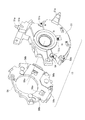
図4は3群ユニット13の構成例を示す分解斜視図であり、図5は正面側から見た3群ユニット13の斜視図であり、図6は背面側から見た3群ユニット13の斜視図である。また、図7は3群ユニット13の断面図であり、図8は3群ユニット13を図7とは別の位置で切断して示す断面図である。
Next, the configuration of the
4 is an exploded perspective view showing a configuration example of the
3群ユニット13は、3群ベース51と、該ベースに取り付けられる2つのコイルユニット52を備える。レンズ13Lを保持するレンズホルダ55と3群ベース51とに亘って複数の弾性部材(本例では3本のバネ54)が掛け渡されている。また、複数(本例では3個)のボール53が、3群ベース51の玉受け部51eにそれぞれ受け入れられた状態で、レンズホルダ55に点接触している。位置センサの保持部材であるセンサホルダ56には、フレキシブルプリント基板57が取り付けられ、センサホルダ56はビス58により3群ベース51に取り付けられる。なお、本実施形態では複数の弾性部材(本例では3本のバネ54)によってレンズホルダ55が3群ベース51の側へ付勢されるが、バネの代わりにマグネットを用いてもよい。この場合、付勢のために新たにマグネットを用意して弾性部材の代わりとしてもよいし、本例のアクチュエータに用いるマグネット55aによって弾性部材の働きを兼用させてもよい。
The
以下、各部材について詳細に説明する。
3群ベース51はカムピン51aと係合部51bを備える。カムピン51aは係合部51bの端部から光軸に直交する方向に突出しており、カム筒33に形成した不図示のカム溝と係合する。係合部51bには、ガイドバー32を係合するための挿通孔が形成されている。3群ベース51の背面(被写体とは反対の側)にはバネ掛け部51c(図6参照)が設けられ、レンズホルダ55には、これらに対応したバネ掛け部55cが設けられている。各バネ掛け部51cと55cとの間に掛けられたバネ54の付勢力により、レンズホルダ55が3群ベース51の側へ付勢される。コイル保持部51dは2箇所設けられ、コイルユニット52を保持する。3群ベース51には2つのコイルユニット52が取り付けられ、該コイルユニットはコイル52aとボビン52bで構成される。その詳細については後述する。3群ベース51の中央部にはレンズホルダ55の一部を受け入れるための凹部51fが形成されている。
Hereinafter, each member will be described in detail.
The
3群ベース51には玉受け部51eが3箇所設けられており、ボール53をそれぞれ受け入れる。ボール53は、玉受け部51eと、レンズホルダ55の玉受け面55b(図7参照)との間に配置され、両者に挟まれた状態で滑らかに転がる。つまり、ボール53は玉受け部51eに受け入れられた状態で玉受け面55bと点接触しているので、レンズホルダ55は3群ベース51に対して、光軸と垂直な面内において滑らかに移動可能である。なお、本例においては、玉受け部51eは3群ベース51に、玉受け面55bはレンズホルダ55に配設されているが、玉受け部がレンズホルダ55に配設され、玉受け面が3群ベース51に配設されていてもよい。また、玉受け部がレンズホルダ55と3群ベース51の両方に配設されていてもよい。
The
レンズ13Lを保持するレンズホルダ55は、90°対向にした2個1組のマグネット55aを有している。すなわち、レンズホルダ55には各マグネット55aの収容部が設けられており、これらが光軸の回りに90°の角度間隔をもって配置されている。なお、マグネット55aの詳細については後述する。
The
センサホルダ56は、ビス58を用いて3群ベース51に固定される。センサホルダ56の保持部56aは位置検出センサ57c(図8参照)を保持する。位置検出センサ57cはマグネット55aに対応する位置にそれぞれ配置され、マグネット55aの磁気検出によってレンズホルダ55の位置を検出する。
The
フレキシブルプリント基板57は前面側の基板部57aと背面側の基板部57bを有する。前面側の基板部57aには位置検出センサ57cが実装され、背面側の基板部57bはコイルユニット52のコイル52aと接続される。前面側の基板部57aはセンサホルダ56の前面側に形成した浅い凹部56bに取り付けられる。また背面側の基板部57bは、3群ベース51の背面にハンダ59により固定されている(図6参照)。
The flexible printed
図9は3群ユニット13を光軸方向から見た正面図であり、センサホルダ56を3群ベース51に取り付ける前の状態を示す。図10は、コイルユニット52とマグネット55aを用いたアクチュエータの駆動部の拡大図である。図10中にA、Bの矢印で示す方向は、紙面内で直交する駆動方向をそれぞれ示しており、マグネット55aはN及びSを付して示すように、着磁方向がB方向、つまりマグネット55aの長辺方向に沿う方向である。dは各駆動方向におけるレンズホルダ55の可動量(最大変位量)を示す。なお本例ではA、B方向の可動量が同じdであるが、仕様によってはA方向とB方向とで可動量が異なっていてもよい。
FIG. 9 is a front view of the
図9に示すように、コイルユニット52のコイル52aは3群ベース51に対して固定されている。光軸に沿う方向から見てレーストラック形状をしたコイル52aは、長辺方向の直線部と、両端の曲線部を有する。また、マグネット55aを備えたレンズホルダ55は、バネ54もしくはマグネットの磁力による付勢力により3群ベース51に近づく方向に付勢され、ボール53を用いた機構によって光軸と垂直な方向に移動可能な状態である。
As shown in FIG. 9, the
図10に示すように光軸方向から見て、マグネット55aの長辺方向(外形長Y参照)とコイル52aの短辺方向(外形長L2参照)は、光軸と直交する面内にてマグネット55aとコイル52aにより発生するローレンツ力の方向(B方向)に平行である。そして、マグネット55aの短辺方向(外形長X参照)とコイル52aの長辺方向は、光軸と直交する面内にてローレンツ力の方向とは直交する方向(A方向)に平行である。
As shown in FIG. 10, when viewed from the optical axis direction, the long side direction of the
不図示の駆動回路からコイル52aへの通電によって電流を流すと、マグネット55aの着磁境界に対して略直交するB方向にて、コイル52とマグネット55aにローレンツ力が発生する。これにより、レンズホルダ55は光軸に直交する方向に移動し、ムービングマグネット型アクチュエータが構成される。このような構成のアクチュエータが、図9のように、レンズ13Lの光軸を中心として90°の角度間隔をもってそれぞれ配置されているので、各駆動部で発生する力が合成される。すなわち、図10に示す一方の駆動部にはB方向の駆動力が発生し、他方の駆動部にはA方向の駆動力が発生するので、これらの駆動力の合成により、レンズホルダ55を光軸と直交する面内の所定の範囲内で自在に移動させることができる。
When a current is passed by energizing the
以下、本実施形態を適用したムービングマグネット型アクチュエータの詳細について、図10を用いて説明する。本図は一方の駆動部、つまり、コイル52aの長辺方向の直線部がA方向と平行な方向に沿って延在し、直方体形状のマグネット55aの長辺がB方向に沿った例を示す。なお、2つの駆動部はレンズ13Lの光軸を含んで図9の上下方向に延びる面に関して鏡面対称性をもって配置されている。つまり、他方の駆動部は、一方の駆動部をレンズ13Lの光軸の回りに90°の角度で回転させれば重ね合わせることができるので、以下では1対の駆動部のうち一方だけを詳説する。
Hereinafter, the details of the moving magnet type actuator to which the present embodiment is applied will be described with reference to FIG. This figure shows an example in which one drive part, that is, the straight part in the long side direction of the
図10にて、コイル52aの長辺方向の直線部長をL1とし、短辺方向の外形長をL2とする。また、マグネット55aの短辺、つまりコイル52aの長辺方向と平行な方向(A方向に平行な方向)における外形長をXとする。そしてマグネット55aの長辺、つまりコイル52aの長辺方向に垂直な方向(駆動力の発生方向であり、B方向)の外形長をYとする。dは、レンズホルダ55の各アクチュエータの駆動方向における可動量(最大変位量)を表す。
In FIG. 10, the length of the straight portion in the long side direction of the
本実施形態では、以下に示す条件(1)乃至(3)を満たすようにコイル52a及びマグネット55aが設計される(括弧内に量的な関係を不等式で示す)。
(1)マグネット55aの外形長Xは、外形長Yより小さいこと(X<Y)。
(2)マグネット55aの外形長Xは、コイル52aの直線部長L1から可動量dの2倍を差し引いた長さより小さいこと(X<L1−2×d)。
(3)マグネット55aの外形長Yは、コイル52aの直線部長L2に可動量dの2倍を足した長さより大きいこと(Y>L2+2×d)。
なお、A方向とB方向とで可動量が異なる場合には、A方向の可動量をdAとし、B方向の可動量をdBとしたとき、条件(2)は「X<L1−2×dA」であり、条件(3)は「Y>L2+2×dB」である。
In the present embodiment, the
(1) The outer length X of the
(2) The outer length X of the
(3) The outer length Y of the
When the movable amount is different between the A direction and the B direction, when the movable amount in the A direction is dA and the movable amount in the B direction is dB, the condition (2) is “X <L1-2 × dA The condition (3) is “Y> L2 + 2 × dB”.
図10(B)はアクチュエータの可動部であるレンズホルダ55が、A方向に対して平行に可動量dまで移動した状態を示す図である。レンズホルダ55が可動量dで移動しても、常にマグネット55aがコイル52aの直線部のみと相対する状態にあることが分かる。つまり、マグネット55aの一部がコイル52aの直線部より外れて、コイル52aの曲線部に対向する位置に来ることはない。このため、本構成ではコイル52aの曲線部の近傍で起こるローレンツ力の方向の乱れによる影響を蒙ることがなくなる。よって、本実施形態によればアクチュエータの駆動を安定化させることができるという効果が得られる。
FIG. 10B is a diagram showing a state in which the
一般的に、振幅の大きい振れのように、より大きな像ブレ量を補正レンズの駆動によって補正しようとする場合、レンズホルダ55の可動量dを大きく設定する必要がある。本実施形態では、外形長Yをただ大きくするのではなく、マグネット55aの外形長Yを長く設定するが、外形長Xを短く設定している。よって、マグネット55aの体積増加を抑えつつ、可動量dまで可動部を移動させるのに必要なローレンツ力を確保することができる。
Generally, when a larger image blur amount is to be corrected by driving the correction lens, such as a shake having a large amplitude, the movable amount d of the
次に、補正レンズを保持した可動部の光軸に対して、直交する面内での回転により生じる影響を低減するための、レンズホルダ55の回転規制について説明する。一般に、可動部の重心は、駆動部が発生する力の方向軸上からずれた位置にあり、像ブレ補正時には可動部を光軸に対して直交する面内で回転させる回転モーメントが発生する。また、外部からの振動や摩擦等によっても可動部を回転させる力が発生する。この回転させる力によって、像ブレ補正動作中に可動部が自在に回転して他の固定部材に接触し、駆動特性の変化や画像の乱れを引き起こす可能性があるため、レンズホルダ55の回転規制を行う必要がある。
Next, the rotation restriction of the
図11は、センサホルダ56と3群ベース51とを分離して背面(撮像素子側の面)側から示した斜視図である。また、図9には組立後のセンサホルダ56の一部を破線で示している。
FIG. 11 is a perspective view of the
センサホルダ56の背面には、光軸方向にて3群ベース側に突出した突起状のストッパー56bが複数個所形成されている。これらのストッパー56bは、レンズホルダ55のマグネット55aを保持している外周部55dを囲むように配置されており、外周部55dに当接することでその移動を規制するための規制部として機能する。センサホルダ56が3群ベース51に取り付けられた状態で、ストッパー56bはマグネット55aの外周部55dの近傍に位置する(図9参照)。つまり、ストッパー56bはマグネット55aの長辺方向に沿う保持部(外周部55d参照)に近接して位置し、かつコイル52aから離間して配置され、光軸に沿う方向から見てコイル52aと重なる位置にある。
On the back surface of the
本例では、センサホルダ56に可動部の回転規制用のストッパー56bを設けており、これらのストッパー56bは、コイル52aから距離を置いた空きスペースに位置している。そのため、本構成によれば、スペース効率のよいローリング防止機構を提供することができる。
In this example, the
図12は、可動部であるレンズホルダ55がローリングした状態を示す図である。本例では、レンズホルダ55の外周部55d(図の右側の長辺部参照)が、センサホルダ56のストッパー56bに当接することにより、レンズホルダ55の回転が規制される。このように、ストッパー56bは、マグネット55aの保持部(外周部55d参照)と当接するため、ストッパー56bをレンズホルダ55の重心に近い場所に配置することで効果的な回転規制を実現できる。
また本実施形態によれば、外部からの衝撃等により、可動部であるレンズホルダ55が大きくローリングを起こした場合でも、バネ54の付勢力によってレンズホルダ55の玉受け面55bと3群ベース51の玉受け部51との間にボール53を常に挟んでいる。図12に示すように、レンズホルダ55の玉受け面55bは3群ベース51の玉受け部51eを覆っているので、玉受け部51eからボール53が脱落することはない。よって、レンズホルダ55は光軸に直交する方向に沿って安定に移動可能である。
FIG. 12 is a diagram illustrating a state in which the
Further, according to the present embodiment, even when the
以上のように本実施形態によれば、マグネットを含む可動部の大型化を抑えつつ、制御性を向上させることができる。 As described above, according to the present embodiment, controllability can be improved while suppressing an increase in the size of the movable part including the magnet.
2 鏡筒ユニット
13 3群ユニット
13L 3群レンズ(光学部材)
15 撮像素子
51 3群ベース
52a コイル
55 レンズホルダ(可動部)
55a マグネット
56 センサホルダ(保持部材)
56b ストッパー(規制部)
57c 位置検出センサ
2
15
56b Stopper (Regulator)
57c Position detection sensor
Claims (8)
前記マグネットの長辺方向及び前記コイルの短辺方向は、前記光軸と直交する面内にて前記マグネットと前記コイルにより発生するローレンツ力の方向に平行であり、かつ前記マグネットの短辺方向及び前記コイルの長辺方向は、前記光軸と直交する面内にて前記ローレンツ力の方向と直交する方向に平行であり、
前記コイルの長辺方向の直線部の長さをL1、前記コイルの短辺方向の外形長をL2とし、前記マグネットにおける前記コイルの長辺方向の外形長をXとし、前記マグネットにおける前記コイルの短辺方向の外形長をYとし、前記可動部の可動量をdとしたとき、
X<Y
X<L1−2×d
Y>L2+2×d
の関係が成り立つことを特徴とする像ブレ補正装置。 An image blur correction apparatus that optically corrects an image blur by driving a movable part including an optical member for image blur correction in a direction orthogonal to the optical axis by an actuator having a coil and a magnet having a rectangular parallelepiped shape ,
The long side direction of the magnet and the short side direction of the coil are parallel to the direction of the Lorentz force generated by the magnet and the coil in a plane orthogonal to the optical axis, and the short side direction of the magnet and the long side direction of the coil, Ri parallel der in a direction perpendicular to the direction of the Lorentz force at plane perpendicular to the optical axis,
The length of the linear portion in the long side direction of the coil is L1, the external length in the short side direction of the coil is L2, the external length in the long side direction of the coil in the magnet is X, and the length of the coil in the magnet is When the outer length in the short side direction is Y and the movable amount of the movable part is d,
X <Y
X <L1-2 × d
Y> L2 + 2 × d
Image blur correction apparatus characterized by the relation holds.
前記位置検出手段を保持する保持部材を更に備え、
前記保持部材は、前記光軸を中心とする前記可動部の回転を規制する規制部を有することを特徴とする請求項1に記載の像ブレ補正装置。 Position detecting means for detecting the position of the movable part;
A holding member for holding the position detecting means;
The image blur correction apparatus according to claim 1 , wherein the holding member includes a restricting portion that restricts rotation of the movable portion around the optical axis.
前記マグネットの長辺方向及び前記コイルの短辺方向は、前記光軸と直交する面内にて前記マグネットと前記コイルにより発生するローレンツ力の方向に平行であり、かつ前記マグネットの短辺方向及び前記コイルの長辺方向は、前記光軸と直交する面内にて前記ローレンツ力の方向と直交する方向に平行であり、 The long side direction of the magnet and the short side direction of the coil are parallel to the direction of the Lorentz force generated by the magnet and the coil in a plane orthogonal to the optical axis, and the short side direction of the magnet and The long side direction of the coil is parallel to a direction orthogonal to the direction of the Lorentz force in a plane orthogonal to the optical axis,
前記コイルの長辺方向の直線部の長さをL1、前記コイルの短辺方向の外形長をL2とし、前記マグネットにおける前記コイルの長辺方向の外形長をXとし、前記マグネットにおける前記コイルの短辺方向の外形長をYとし、前記コイルの長辺方向と平行な方向における前記可動部の可動量をdAとし、前記コイルの短辺方向と平行な方向における前記可動部の可動量をdBとしたとき、The length of the linear portion in the long side direction of the coil is L1, the external length in the short side direction of the coil is L2, the external length in the long side direction of the coil in the magnet is X, and the length of the coil in the magnet is The outer length in the short side direction is Y, the movable amount of the movable part in the direction parallel to the long side direction of the coil is dA, and the movable amount of the movable part in the direction parallel to the short side direction of the coil is dB. When
X<YX <Y
X<L1−2×dAX <L1-2 × dA
Y>L2+2×dBY> L2 + 2 × dB
の関係が成り立つことを特徴とする像ブレ補正装置。An image blur correction device characterized in that
前記像ブレ補正装置を通して得た被写体からの光像を電気信号に変換する撮像素子を備えたことを特徴とする撮像装置。
An image blur correction device according to any one of claims 1 to 7,
An image pickup apparatus comprising an image pickup element for converting a light image from a subject obtained through the image blur correction apparatus into an electric signal.
Priority Applications (1)
| Application Number | Priority Date | Filing Date | Title |
|---|---|---|---|
| JP2010187475A JP5582922B2 (en) | 2010-08-24 | 2010-08-24 | Image blur correction apparatus and imaging apparatus |
Applications Claiming Priority (1)
| Application Number | Priority Date | Filing Date | Title |
|---|---|---|---|
| JP2010187475A JP5582922B2 (en) | 2010-08-24 | 2010-08-24 | Image blur correction apparatus and imaging apparatus |
Publications (3)
| Publication Number | Publication Date |
|---|---|
| JP2012047824A JP2012047824A (en) | 2012-03-08 |
| JP2012047824A5 JP2012047824A5 (en) | 2013-09-12 |
| JP5582922B2 true JP5582922B2 (en) | 2014-09-03 |
Family
ID=45902809
Family Applications (1)
| Application Number | Title | Priority Date | Filing Date |
|---|---|---|---|
| JP2010187475A Active JP5582922B2 (en) | 2010-08-24 | 2010-08-24 | Image blur correction apparatus and imaging apparatus |
Country Status (1)
| Country | Link |
|---|---|
| JP (1) | JP5582922B2 (en) |
Families Citing this family (6)
| Publication number | Priority date | Publication date | Assignee | Title |
|---|---|---|---|---|
| JP5895464B2 (en) * | 2011-11-17 | 2016-03-30 | 株式会社ニコン | Lens barrel and imaging device |
| KR102062812B1 (en) * | 2012-05-07 | 2020-01-06 | 엘지이노텍 주식회사 | Camera Module |
| JP2014089325A (en) * | 2012-10-30 | 2014-05-15 | Canon Inc | Image blur correction device, optical instrument, and imaging apparatus |
| JP6381205B2 (en) * | 2013-12-19 | 2018-08-29 | キヤノン株式会社 | Optical apparatus, imaging device, and lens barrel |
| KR102534815B1 (en) * | 2016-04-28 | 2023-05-19 | 엘지이노텍 주식회사 | Lens driving device, camera module and optical apparatus |
| CN113448048A (en) * | 2016-04-28 | 2021-09-28 | Lg伊诺特有限公司 | Lens driving mechanism, camera module and optical device |
Family Cites Families (2)
| Publication number | Priority date | Publication date | Assignee | Title |
|---|---|---|---|---|
| JP2008233524A (en) * | 2007-03-20 | 2008-10-02 | Tamron Co Ltd | Actuator, lens unit equipped therewith, and camera |
| JP5308457B2 (en) * | 2009-01-23 | 2013-10-09 | 株式会社ケンコー・トキナー | Voice coil motor for driving correction lens, camera shake correction device, interchangeable lens and optical device |
-
2010
- 2010-08-24 JP JP2010187475A patent/JP5582922B2/en active Active
Also Published As
| Publication number | Publication date |
|---|---|
| JP2012047824A (en) | 2012-03-08 |
Similar Documents
| Publication | Publication Date | Title |
|---|---|---|
| JP6613005B1 (en) | Anti-vibration mechanism for bending imaging apparatus, camera, and portable electronic device | |
| KR102383944B1 (en) | Camera module and portable electronic device including the same | |
| US7747149B2 (en) | Optical apparatus having image-blur correction/reduction system | |
| EP2813880B1 (en) | Camera lens assembly | |
| KR101525816B1 (en) | Image shake correction device | |
| JP4804564B2 (en) | Optical apparatus having shake correction device | |
| JP4491565B2 (en) | Camera shake correction device for camera lens assembly | |
| JP6960983B2 (en) | Imaging device with image stabilization function | |
| JP5582922B2 (en) | Image blur correction apparatus and imaging apparatus | |
| JP2012203319A (en) | Correction apparatus for image blurring and imaging apparatus | |
| JP5955609B2 (en) | Lens drive device | |
| KR20120098535A (en) | Position controller for removable optical element | |
| US9798158B2 (en) | Optical apparatus capable of retracting optical element from optical path | |
| JP6960985B2 (en) | Imaging device with image stabilization function | |
| JP2022136419A (en) | Optical unit with shake correction function | |
| JP2007171299A (en) | Lens barrel | |
| US20240045309A1 (en) | Optical element drive device, camera module, and camera mounting device | |
| JP5867994B2 (en) | Lens barrel and optical equipment | |
| JP2016057386A (en) | Image tremor correction device and optical device having the same | |
| JP7096932B2 (en) | Optical member drive device, camera device, and electronic device | |
| US20220187565A1 (en) | Lens barrel and optical apparatus | |
| KR102642909B1 (en) | Sensor actuator and camera moduel including the same | |
| JP7362377B2 (en) | Lens barrel and optical equipment including it | |
| JP2012022204A (en) | Image blur correcting device, lens barrel, imaging device, and portable information terminal | |
| JP2011150086A (en) | Swing correcting device, and optical apparatus using the same |
Legal Events
| Date | Code | Title | Description |
|---|---|---|---|
| A521 | Written amendment |
Free format text: JAPANESE INTERMEDIATE CODE: A523 Effective date: 20130801 |
|
| A621 | Written request for application examination |
Free format text: JAPANESE INTERMEDIATE CODE: A621 Effective date: 20130801 |
|
| A977 | Report on retrieval |
Free format text: JAPANESE INTERMEDIATE CODE: A971007 Effective date: 20140319 |
|
| A131 | Notification of reasons for refusal |
Free format text: JAPANESE INTERMEDIATE CODE: A131 Effective date: 20140408 |
|
| A521 | Written amendment |
Free format text: JAPANESE INTERMEDIATE CODE: A523 Effective date: 20140526 |
|
| TRDD | Decision of grant or rejection written | ||
| A01 | Written decision to grant a patent or to grant a registration (utility model) |
Free format text: JAPANESE INTERMEDIATE CODE: A01 Effective date: 20140617 |
|
| A61 | First payment of annual fees (during grant procedure) |
Free format text: JAPANESE INTERMEDIATE CODE: A61 Effective date: 20140715 |
|
| R151 | Written notification of patent or utility model registration |
Ref document number: 5582922 Country of ref document: JP Free format text: JAPANESE INTERMEDIATE CODE: R151 |