JP5582197B2 - Vehicle and steering control method thereof - Google Patents
Vehicle and steering control method thereof Download PDFInfo
- Publication number
- JP5582197B2 JP5582197B2 JP2012546689A JP2012546689A JP5582197B2 JP 5582197 B2 JP5582197 B2 JP 5582197B2 JP 2012546689 A JP2012546689 A JP 2012546689A JP 2012546689 A JP2012546689 A JP 2012546689A JP 5582197 B2 JP5582197 B2 JP 5582197B2
- Authority
- JP
- Japan
- Prior art keywords
- steering
- straightness
- wheel
- vehicle
- control
- Prior art date
- Legal status (The legal status is an assumption and is not a legal conclusion. Google has not performed a legal analysis and makes no representation as to the accuracy of the status listed.)
- Expired - Fee Related
Links
Images


Classifications
-
- B—PERFORMING OPERATIONS; TRANSPORTING
- B62—LAND VEHICLES FOR TRAVELLING OTHERWISE THAN ON RAILS
- B62D—MOTOR VEHICLES; TRAILERS
- B62D5/00—Power-assisted or power-driven steering
- B62D5/001—Mechanical components or aspects of steer-by-wire systems, not otherwise provided for in this maingroup
-
- B—PERFORMING OPERATIONS; TRANSPORTING
- B62—LAND VEHICLES FOR TRAVELLING OTHERWISE THAN ON RAILS
- B62D—MOTOR VEHICLES; TRAILERS
- B62D5/00—Power-assisted or power-driven steering
- B62D5/04—Power-assisted or power-driven steering electrical, e.g. using an electric servo-motor connected to, or forming part of, the steering gear
- B62D5/0457—Power-assisted or power-driven steering electrical, e.g. using an electric servo-motor connected to, or forming part of, the steering gear characterised by control features of the drive means as such
- B62D5/046—Controlling the motor
-
- B—PERFORMING OPERATIONS; TRANSPORTING
- B62—LAND VEHICLES FOR TRAVELLING OTHERWISE THAN ON RAILS
- B62D—MOTOR VEHICLES; TRAILERS
- B62D7/00—Steering linkage; Stub axles or their mountings
- B62D7/18—Steering knuckles; King pins
Description
本発明は、直進性を担保することができる車両及びその操舵制御方法に関する。 The present invention relates to a vehicle that can ensure straight traveling performance and a steering control method thereof.
従来、車両用のサスペンション装置では、キングピン軸の設定によって、目的とするサスペンション性能の実現を図っている。
例えば、特許文献1に記載の技術では、キングピンを構成する上下ピボット点の転舵時における車両前後方向の動きを抑制するリンク配置とすることにより、操縦性・安定性を向上させることとしている。Conventionally, in a suspension device for a vehicle, a desired suspension performance is achieved by setting a kingpin shaft.
For example, in the technique described in
しかしながら、車両の走行中に転舵を行った場合、走行速度に応じた横力がタイヤ接地点に入力するところ、特許文献1に記載の技術では、この横力による影響を考慮していない。そのため、転舵時にキングピン軸周りに発生するモーメントの低減において改善の余地がある。即ち、従来の車両用のサスペンション装置においては、操縦性・安定性の向上を図る上で改善の余地があった。
本発明の課題は、車両におけるサスペンション装置の操縦性・安定性を向上させることである。However, when steering is performed while the vehicle is traveling, the lateral force corresponding to the traveling speed is input to the tire ground contact point. However, the technique described in
The subject of this invention is improving the controllability and stability of the suspension apparatus in a vehicle.
以上の課題を解決するため、本発明に係る自動車の一態様は、転舵輪を転舵する転舵制御装置と、転舵輪を車体に懸架するサスペンション装置とを備え、サスペンション装置は、キングピン軸をステアリングホイールの中立位置でタイヤ接地面内を通るように設定し、前記転舵制御装置は前記アクチュエータを作動させて転舵輪にセルフアライニングのための復元力を発生することで転舵輪を転舵し、車両の直進性を担保する。 In order to solve the above-described problems, an aspect of an automobile according to the present invention includes a steering control device that steers a steered wheel and a suspension device that suspends the steered wheel on a vehicle body, and the suspension device has a kingpin shaft. The steering wheel is set to pass through the tire contact surface at the neutral position of the steering wheel, and the steering control device operates the actuator to generate a restoring force for self-aligning the steered wheel to steer the steered wheel. And ensure the straightness of the vehicle.
本発明によれば、キングピン軸周りのモーメントをより小さくすることができるため、より小さいラック軸力で転舵を行うことができる。このため、例えばより小さい力で車輪の向きを制御できる。そして、車両の直進性は転舵制御装置で担保することができる。
したがって、車両の操縦性・安定性を向上させることができる。According to the present invention, since the moment around the kingpin axis can be made smaller, the steering can be performed with a smaller rack axial force. For this reason, for example, the direction of the wheel can be controlled with a smaller force. Further, the straightness of the vehicle can be secured by the steering control device.
Therefore, the controllability and stability of the vehicle can be improved.
以下、図を参照して本発明を適用した自動車の実施の形態を説明する。
(第1実施形態)
(構成)
図1は、本発明の原理的構成である第1実施形態に係る自動車Cの構成を示す概略図である。
図1において、自動車1は、車体1Aを備えている。この車体1Aには、車輪WFR,WFL,WRR,WRLを支持するサスペンション装置1Bと、前輪側の転舵輪WFR及びWFLを操舵する操舵装置SSとが設けられている。
操舵装置SSは、ステアリング機構SMとこのステアリング機構に操舵補助力を与える電動パワーステアリング装置EPとを備えている。Embodiments of an automobile to which the present invention is applied will be described below with reference to the drawings.
(First embodiment)
(Constitution)
FIG. 1 is a schematic diagram showing the configuration of an automobile C according to the first embodiment, which is the basic configuration of the present invention.
In FIG. 1, an
The steering device SS includes a steering mechanism SM and an electric power steering device EP that applies a steering assist force to the steering mechanism.
ステアリング機構SMは、入力側ステアリング軸SSi、出力側ステアリング軸SSo、ステアリングホイールSW、ピニオンギアPG、ラック軸LS、タイロッドTRを備えている。
入力側ステアリング軸SSiには、車両後方側の先端にステアリングホイールSWが装着されている。そして、入力側ステアリング軸SSi及び出力側ステアリング軸SSoは、車体1Aに回転可能に支持されており、互いにトーションバー(図示せず)を介して連結されている。The steering mechanism SM includes an input side steering shaft SSi, an output side steering shaft SSo, a steering wheel SW, a pinion gear PG, a rack shaft LS, and a tie rod TR.
A steering wheel SW is mounted on the input-side steering shaft SSi at the tip on the vehicle rear side. The input side steering shaft SSi and the output side steering shaft SSo are rotatably supported by the
出力側ステアリング軸SSoの車両前端側には、ピニオンギアPGが連結されており、このピニオンギアPGがラック軸LSに形成されたラックギアに噛合してピニオンアンドラック機構が形成されている。このピニオンアンドラック機構では、ステアリングホイールSWの回転運動を車幅方向の直線運動に変換する。そして、ラック軸LSの両端と転舵輪WFR及びWRLとの間にそれぞれタイロッドTRが連結されている。これらタイロッドTRは、ラック軸LSの両端部と車輪WFR,WFLのナックルアームとを、ボールジョイントを介してそれぞれ連結している。 A pinion gear PG is connected to the vehicle front end side of the output side steering shaft SSo, and this pinion gear PG meshes with a rack gear formed on the rack shaft LS to form a pinion and rack mechanism. In this pinion and rack mechanism, the rotational motion of the steering wheel SW is converted into a linear motion in the vehicle width direction. Tie rods TR are coupled between both ends of the rack shaft LS and the steered wheels WFR and WRL. These tie rods TR connect both ends of the rack shaft LS and the knuckle arms of the wheels WFR and WFL via ball joints.
一方、電動パワーステアリング装置EPは、入力側ステアリング軸SSiに装着されたステアリングホイールSWの操舵角を検出する操舵角センサASと、入力側ステアリング軸SSi及び出力側ステアリング軸SSoとの回転角差に基づいて操舵トルクを検出する操舵トルクセンサTSと、出力側ステアリング軸SSoに対して操舵制御力を伝達する電動アクチュエータEAと、この電動アクチュエータEAの回転角を検出する回転角センサRSとを備えている。ここで、電動アクチュエータEAは、電動モータで構成され、モータ軸と一体に回転するギアが出力側ステアリング軸SSoの一部に形成されたギアに噛合しており、出力側ステアリング軸SSoを回転させる。 On the other hand, the electric power steering device EP is based on the difference in rotation angle between the steering angle sensor AS that detects the steering angle of the steering wheel SW mounted on the input side steering shaft SSi, and the input side steering shaft SSi and the output side steering shaft SSo. A steering torque sensor TS that detects a steering torque based on the electric actuator EA that transmits a steering control force to the output-side steering shaft SSo, and a rotation angle sensor RS that detects a rotation angle of the electric actuator EA. Yes. Here, the electric actuator EA is composed of an electric motor, and a gear that rotates integrally with the motor shaft meshes with a gear that is formed in a part of the output side steering shaft SSo, and rotates the output side steering shaft SSo. .
また、電動パワーステアリング装置EPは、電動アクチュエータEAを駆動制御する転舵制御装置CTと、各車輪WFR〜WRLの車輪速を検出する車輪速センサWSFR〜WSRLと、車両状態パラメータ取得部CPとを備えている。
車両状態パラメータ取得部CPは、車輪速センサWFR〜WRLから出力される車輪の回転速度を示すパルス信号を基に車速を取得する。また、車両状態パラメータ取得部CPは、車速と各車輪の回転速度とを基に、各車輪のスリップ率を取得する。そして、車両状態パラメータ取得部CPは、取得した各パラメータを制御装置CSに出力する。The electric power steering device EP includes a steering control device CT for driving and controlling the electric actuator EA, wheel speed sensors WSFR to WSRL for detecting the wheel speeds of the wheels WFR to WRL, and a vehicle state parameter acquisition unit CP. I have.
The vehicle state parameter acquisition unit CP acquires the vehicle speed based on a pulse signal indicating the rotational speed of the wheels output from the wheel speed sensors WFR to WRL. Moreover, vehicle state parameter acquisition part CP acquires the slip ratio of each wheel based on a vehicle speed and the rotational speed of each wheel. And vehicle state parameter acquisition part CP outputs each acquired parameter to control apparatus CS.
転舵制御装置CTには、車両状態パラメータ取得部CPから入力される各パラメータの他、操舵角センサ4で検出した操舵角θs、操舵トルクセンサTSで検出した操舵トルクTs、回転角センサRSで検出したアクチュエータ回転角θaが入力されている。
この転舵制御装置CTは、パワーステアリング制御部PCと直進性担保部SGとを備えている。パワーステアリング制御部PCは、操舵トルクTsと車速Vとに基づいて目標補助操舵トルクを算出し、算出した目標操舵補助トルクに基づいて電動アクチュエータEAを駆動する駆動電流を算出し、この駆動電流を電動アクチュエータEAに供給して電動アクチュエータEAを駆動制御する。In addition to the parameters input from the vehicle state parameter acquisition unit CP, the steering control device CT includes a steering angle θs detected by the
The steering control device CT includes a power steering control unit PC and a straight travel guarantee unit SG. The power steering control unit PC calculates a target auxiliary steering torque based on the steering torque Ts and the vehicle speed V, calculates a driving current for driving the electric actuator EA based on the calculated target steering auxiliary torque, and calculates the driving current. The electric actuator EA is supplied and controlled to drive the electric actuator EA.
直進性担保部SGは、後述するようにサスペンション装置1Bの直進性を補完する直進性補完制御を行う。
車輪WFR,WFL,WRR,WRLは、ホイールハブ機構WHにタイヤを取り付けて構成したものであり、サスペンション装置1Bを介して車体1Aに設置してある。これらのうち、転舵輪となる前輪(車輪WFR,WFL)は、タイロッド15によってナックルアームが揺動することにより、車体1Aに対する車輪WFR,WFLの向きが変化する。As will be described later, the rectilinearity ensuring unit SG performs rectilinear complementation control that complements the rectilinearity of the
The wheels WFR, WFL, WRR, WRL are configured by attaching tires to the wheel hub mechanism WH, and are installed in the
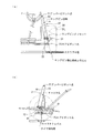
図2は、第1実施形態に係るサスペンション装置1Bの構成を模式的に示す斜視図である。図3は、図2のサスペンション装置1Bの構成を模式的に示す平面図である。図4は、図2のサスペンション装置1Bの構成を模式的に示す(a)部分正面図および(b)部分側面図である。
図2から図4に示すように、サスペンション装置1Bは、ホイールハブ機構WHに取り付けられた車輪17FR,17FLを懸架しており、車輪17FR,17FLを回転自在に支持する車軸(アクスル)32を有するアクスルキャリア33、車体側の支持部から車体幅方向に配置されてアクスルキャリア33に連結する複数のリンク部材、及びコイルスプリング等のバネ部材34を備えている。FIG. 2 is a perspective view schematically showing the configuration of the
As shown in FIGS. 2 to 4, the
複数のリンク部材は、ロアリンク部材である第1リンク(第1リンク部材)37と第2リンク(第2リンク部材)38、タイロッド(タイロッド部材)15、および、ストラット(バネ部材34およびショックアブソーバ40)から構成されている。本実施形態において、サスペンション装置1Bはストラット式のサスペンションであり、バネ部材34およびショックアブソーバ40が一体となったストラットの上端が、車軸32より上方に位置する車体側の支持部に連結する(以下、ストラットの上端を適宜「アッパーピボット点」と称する。)。ロアアームを構成する第1リンク37と第2リンク38は、車軸32より下方に位置する車体側の支持部とアクスルキャリア33の下端を連結する。このロアアームは、車体側と2箇所で支持され、車軸32側と1箇所で連結されるAアーム形状を有している(以下、ロアアームとアクスルキャリア33との連結部を適宜「ロアピボット点」と称する。)。
The plurality of link members include a first link (first link member) 37 and a second link (second link member) 38, tie rods (tie rod members) 15, and struts (
タイロッド15は、車軸32の下側に位置して、ラック軸14とアクスルキャリア33を連結し、ラック軸14は、ステアリングホイール2からの回転力(操舵力)が伝達されて転舵用の軸力を発生させる。従って、タイロッド15により、ステアリングホイール2の回転に応じてアクスルキャリア33に車幅方向の軸力が加えられ、アクスルキャリア33を介して車輪17FR,17FLが転舵される。
The
本願発明においては、ステアリングホイール2の中立位置すなわち転舵輪17FL及び17FRが直進走行状態となっている状態で、上記サスペンション装置1Bのアッパーピボット点P1及びロアピボット点P2を結ぶキングピン軸KSを、キングピン軸KSの路面接地点がタイヤ接地面内に位置し、キャスタートレイルがタイヤ接地面内に位置するよう設定している。より具体的には、本実施形態におけるサスペンション装置1Bでは、キャスター角をゼロに近い値とし、キャスタートレイルがゼロに近づくようにキングピン軸KSを設定している。これにより、転舵時のタイヤ捻りトルクを低減でき、キングピン軸KS周りのモーメントをより小さくすることができる。また、スクラブ半径はゼロ以上のポジティブスクラブとしている。これにより、転舵時のタイヤ横滑り角に対し、スクラブ半径分のキャスタートレイルが変化することから、直進性を確保することができる。
In the present invention, the kingpin axis KS connecting the upper pivot point P1 and the lower pivot point P2 of the
以下、サスペンション装置1Bにおけるサスペンションジオメトリについて詳細に検討する。
(ラック軸力成分の分析)
図5は、転舵時におけるラックストロークとラック軸力との関係を示す図である。
図5に示すように、ラック軸力成分には、主にタイヤの捻りトルクと、車輪の持ち上げトルクとが含まれ、これらのうち、タイヤの捻りトルクが支配的である。
したがって、タイヤの捻りトルクを小さくすることで、ラック軸力を低減することができることとなる。Hereinafter, the suspension geometry in the
(Analysis of rack axial force component)
FIG. 5 is a diagram illustrating the relationship between the rack stroke and the rack axial force during steering.
As shown in FIG. 5, the rack axial force component mainly includes a tire twisting torque and a wheel lifting torque, and of these, the tire twisting torque is dominant.
Therefore, the rack axial force can be reduced by reducing the torsional torque of the tire.
(タイヤの捻りトルク最小化)
図6は、転舵時におけるタイヤ接地面中心の軌跡を示す図である。
図6においては、転舵時におけるタイヤ接地面中心の移動量が大きい場合と小さい場合とを併せて示している。
上記ラック軸力成分の分析結果より、ラック軸力を低減するためには、転舵時のタイヤ捻りトルクを最小化することが有効である。
転舵時のタイヤ捻りトルクを最小化するためには、図6に示すように、タイヤ接地面中心の軌跡の変化をより小さくすれば良い。
即ち、タイヤ接地面中心とキングピン接地点を一致させることで、タイヤ捩りトルクを最小化できる。
具体的には、後述するようにキャスタートレイル0mm、スクラブ半径0mm以上のポジティスクラブとすることが有効である。(Minimizing tire twisting torque)
FIG. 6 is a diagram illustrating a trajectory of the center of the tire ground contact surface at the time of turning.
In FIG. 6, the case where the amount of movement of the center of the tire contact surface at the time of turning is large and the case where it is small are shown.
From the analysis result of the rack axial force component, in order to reduce the rack axial force, it is effective to minimize the tire twisting torque at the time of turning.
In order to minimize the tire twisting torque at the time of turning, as shown in FIG. 6, the change in the trajectory at the center of the tire contact surface may be made smaller.
That is, the tire torsion torque can be minimized by matching the center of the tire contact surface with the kingpin contact point.
Specifically, as will be described later, it is effective to make a positive club having a caster trail of 0 mm and a scrub radius of 0 mm or more.
(キングピン傾角の影響)
図7は、キングピン傾角とスクラブ半径とを軸とする座標において、ラック軸力の分布の一例を示す等値線図である。
図7においては、ラック軸力が小、中および大の3つの場合における等値線を例として示している。
タイヤ捻りトルク入力に対し、キングピン傾角が大きくなるほど、その回転モーメントが大きくなり、ラック軸力は大きくなる。したがって、キングピン傾角としては、一定の値より小さく設定することが望まれるが、スクラブ半径との関係から、例えばキングピン傾角15度以下とすると、ラック軸力を望ましいレベルまで小さくすることができる。(Effect of kingpin tilt angle)
FIG. 7 is an isoline diagram showing an example of rack axial force distribution at coordinates with the kingpin tilt angle and scrub radius as axes.
In FIG. 7, an isoline in the case where the rack axial force is small, medium and large is shown as an example.
As the kingpin tilt angle increases with respect to tire torsion torque input, the rotational moment increases and the rack axial force increases. Therefore, it is desirable to set the kingpin tilt angle to be smaller than a certain value, but from the relationship with the scrub radius, for example, if the kingpin tilt angle is 15 degrees or less, the rack axial force can be reduced to a desired level.
なお、図7における一点鎖線(境界線)で囲んだ領域は、旋回の限界領域において、横力が摩擦の限界を超える値と推定できるキングピン傾角15度より小さく、かつ、上記タイヤ捻りトルクの観点から、スクラブ半径が0mm以上の領域を示している。本実施形態では、この領域(横軸においてキングピン傾角が15度より減少する方向で、縦軸においてスクラブ半径がゼロより増加する方向)を、より設定に適した領域としている。 7 is smaller than a kingpin inclination angle of 15 degrees at which the lateral force can be estimated to exceed the friction limit in the turning limit region, and the viewpoint of the tire twisting torque. Thus, an area having a scrub radius of 0 mm or more is shown. In the present embodiment, this region (the direction in which the kingpin tilt angle decreases from 15 degrees on the horizontal axis and the direction in which the scrub radius increases from zero on the vertical axis) is a region that is more suitable for setting.
具体的にスクラブ半径とキングピン傾角とを決定する場合には、例えば、図7に示すラック軸力の分布を示す等値線をn次曲線(nは2以上の整数)として近似し、上記一点鎖線で囲んだ領域の中から、n次曲線の変曲点(またはピーク値)の位置によって定めた値を採用することができる。 Specifically, when determining the scrub radius and the kingpin tilt angle, for example, the isoline indicating the rack axial force distribution shown in FIG. 7 is approximated as an nth-order curve (n is an integer of 2 or more), A value determined by the position of the inflection point (or peak value) of the n-th order curve from the region surrounded by the chain line can be adopted.
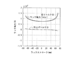
(ラック軸力の最小化例)
図8は、本実施形態に係るサスペンション装置1Bにおけるラック軸力の解析結果を示す図である。
図8に示す実線は、図2〜4に示すサスペンション構造において、キャスター角0度、キャスタートレイル0mm、スクラブ半径+10mmに設定した場合のラック軸力特性を示している。
なお、図8においては、サスペンション装置1Bと同方式の懸架構造で、キングピン軸に関する設定をステアバイワイヤ方式の操舵装置を備えていない構造に合わせて設定したときの比較例(破線)を併せて示している。
図8に示すように、上記検討結果に従って設定すると、ラック軸力は比較例に対し約30%低減することができる。(Example of rack axial force minimization)
FIG. 8 is a diagram showing the analysis result of the rack axial force in the
The solid line shown in FIG. 8 indicates the rack axial force characteristics in the suspension structure shown in FIGS. 2 to 4 when the caster angle is set to 0 degree, the caster trail is set to 0 mm, and the scrub radius is +10 mm.
FIG. 8 also shows a comparative example (broken line) when the setting relating to the kingpin axis is set in accordance with a structure that does not include a steer-by-wire steering device in the same suspension structure as the
As shown in FIG. 8, when set according to the above examination results, the rack axial force can be reduced by about 30% compared to the comparative example.
このように、キャスター角を0度とすることは、サスペンション剛性を向上させることができ、また、キャスタートレイル0mmとすることは、キングピン軸KSの路面着地点と横力との関係を示す図9において符号3で示すように、キングピン軸KSの路面着地点がタイヤ接地面におけるタイヤ接地中心点(着力点)Oに一致させることを意味し、これにより大きな横力低減効果を向上させることができる。なお、タイヤ接地中心点(着力点)Oを含むタイヤ接地面内のキングピン軸KSの接地点が符号2及び符号4である場合にも、キングピン軸KSの接地点が符号1及び符号5で示すようにタイヤ接地面から前後方向に外れた位置とする場合に比較して横力を小さくすることができる。特に、キングピン軸KSの接地点がタイヤ接地中心点(着力点)より車両前方側とした場合の方がタイヤ接地中心点(着力点)より車両後方とした場合に比較して横力を小さく抑制することができる。
Thus, setting the caster angle to 0 degrees can improve the suspension rigidity, and setting the caster trail to 0 mm shows the relationship between the landing point of the kingpin axis KS and the lateral force. As shown by
(ポジティブスクラブによる直進性確保)
図10は、ポジティブスクラブとした場合のセルフアライニングトルクを説明する概念図である。この図10において、転舵時にタイヤ接地中心点(着力点)Oに車体の旋回外側に向かう遠心力が作用すると、この遠心力に抗するように旋回中心に向かう横力が発生する。なお、βは横すべり角である。
図10に示すように、タイヤに働く復元力(セルフアライニングトルク)は、キャスタートレイル、ニューマチックトレイルの和に比例して大きくなる。(Ensuring straightness by positive scrub)
FIG. 10 is a conceptual diagram for explaining the self-aligning torque in the case of a positive scrub. In FIG. 10, when a centrifugal force directed toward the outer side of turning of the vehicle body acts on the tire grounding center point (force point) O during turning, a lateral force toward the turning center is generated against the centrifugal force. Note that β is a side slip angle.
As shown in FIG. 10, the restoring force (self-aligning torque) acting on the tire increases in proportion to the sum of the caster trail and the pneumatic trail.
ここで、ポジティブスクラブの場合、キングピン軸の接地点から、タイヤ中心を通るタイヤの横すべり角β方向の直線に下ろした垂線の足の位置によって定まるホイールセンタからの距離εc(図10参照)をキャスタートレイルとみなすことができる。
そのため、ポジティブスクラブのスクラブ半径が大きければ大きいほど、転舵時にタイヤに働く復元力は大きくなる。
本実施形態においては、キャスター角を0に近づけることによる直進性への影響を、ポジティブスクラブとすることで低減するものである。Here, in the case of positive scrubbing, the distance εc (see FIG. 10) from the wheel center determined by the position of the foot of the perpendicular line drawn from the grounding point of the kingpin shaft to the straight line in the direction of the side slip angle β of the tire passing through the tire center. Can be considered a trail.
Therefore, the greater the scrub radius of the positive scrub, the greater the restoring force acting on the tire during turning.
In the present embodiment, the effect on straight running performance due to the caster angle approaching 0 is reduced by using a positive scrub.
(サスペンション設計例)
本出願人によれば、図2〜4に示すサスペンション装置1Bの構成において、上記検討結果に従い、キングピン傾角13.8度、キャスタートレイル0mm、スクラブ半径5.4mm(ポジティブスクラブ)、キャスター角5.2度、ホイールセンタの高さにおけるキングピンオフセット86mmとした場合、ラック軸力を約30%低減できることを確認している。(Suspension design example)
According to the present applicant, in the configuration of the
上記設計値については、制動時に、サスペンションロアリンクが車両後方へ移動し、このときキングピン下端も同様に車両後方へ移動するため、キャスター角は一定の後傾をとることとしたものである。ちなみに、キャスター角0度以下の場合(キングピン軸KSが前傾している場合)、転舵制動時ラックモーメントが大きくなるため、ラック軸力が増大する。したがって、キングピン軸KSの位置を上記のように規定する。
即ち、キングピンロアピボット点(仮想ピボットも含む)はホイールセンタ後方、キングピンアッパーピボット点(仮想ピボットも含む)はロアピボット点前方に位置する構成とする。Regarding the design value, the suspension lower link moves to the rear of the vehicle at the time of braking, and the lower end of the kingpin moves to the rear of the vehicle at the same time. Therefore, the caster angle has a constant backward inclination. Incidentally, when the caster angle is 0 degrees or less (when the kingpin axis KS is tilted forward), the rack moment at the time of steering braking is increased, so that the rack axial force is increased. Therefore, the position of the kingpin axis KS is defined as described above.
That is, the kingpin lower pivot point (including the virtual pivot) is positioned behind the wheel center, and the kingpin upper pivot point (including the virtual pivot) is positioned forward of the lower pivot point.
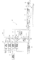
次に、転舵制御装置CTの具体的構成を図11〜図13について説明する。
パワーステアリング制御部PCは、図11に示すように、目標補助トルク電流指令値演算部TOとアクチュエータ電流制御部ACとを備えている。目標補助トルク電流指令値演算部TOは、操舵トルクセンサTSで検出した操舵トルクTsと車速Vとに基づいて制御マップを参照して操舵トルクTsに応じた目標補助トルク電流指令値It*を算出し、算出した目標補助トルク電流指令値It*を、加算器ADに出力する。この加算器ADでは、目標補助トルク電流指令値It*に後述する直進性担保用電流指令値Isa*を加算して目標アクチュエータ電流Ia*を算出し、算出した目標アクチュエータ電流Ia*を減算器SBに出力する。この減算器SBにはアクチュエータ電流センサCSで検出される電動アクチュエータEAに供給されるアクチュエータ電流Iadがフィードバックされている。したがって、減算器SBで、目標アクチュエータ電流指令値Ia*からアクチュエータ電流Iadを減算して電流偏差ΔIを算出する。Next, a specific configuration of the steering control device CT will be described with reference to FIGS.
As shown in FIG. 11, the power steering control unit PC includes a target auxiliary torque current command value calculation unit TO and an actuator current control unit AC. The target auxiliary torque current command value calculation unit TO calculates a target auxiliary torque current command value It * corresponding to the steering torque Ts with reference to the control map based on the steering torque Ts detected by the steering torque sensor TS and the vehicle speed V. Then, the calculated target auxiliary torque current command value It * is output to the adder AD. In the adder AD, a target actuator current Ia * is calculated by adding a straight travel guarantee current command value Isa * described later to the target auxiliary torque current command value It * , and the calculated target actuator current Ia * is subtracted by the subtractor SB. Output to. An actuator current Iad supplied to the electric actuator EA detected by the actuator current sensor CS is fed back to the subtractor SB. Accordingly, the subtractor SB subtracts the actuator current Iad from the target actuator current command value Ia * to calculate the current deviation ΔI.
アクチュエータ電流制御部ACは、減算器SBから入力される電流偏差ΔIを例えばPID制御してアクチュエータ電流Iadを算出し、算出したアクチュエータ電流Iadを電動アクチュエータEAに出力する。
一方、直進性担保部SGでは、セルフアライニングトルクTsaを算出し、算出したセルフアライニングトルクTsaに基づいてサスペンション装置1Bの直進性を担保する直進性担保用電流指令値Isa*を演算する。この直進性担保部SGの具体的構成は、左右の駆動輪駆動力を配分制御する駆動力制御装置DCから出力される左右輪の駆動力TR及びTLが入力されると共に、操舵トルクセンサSTで検出した操舵トルクTsが入力され、これらに基づいてセルフアライニングトルクTsaを算出する。また、直進性担保部SGでは、算出したセルフアライニングトルクTsaに所定電流ゲインKiを乗算して直進性担保用電流指令値Isa*(=Ki・Tsa)を算出する。The actuator current control unit AC calculates the actuator current Iad by performing, for example, PID control on the current deviation ΔI input from the subtractor SB, and outputs the calculated actuator current Iad to the electric actuator EA.
On the other hand, the straight travel guarantee unit SG calculates the self-aligning torque Tsa, and calculates a straight travel guarantee current command value Isa * that secures the straight travel of the
ここで、直進性担保部SGにおけるセルフアライニングトルクTsaの算出は、先ず、左右輪の駆動力TR及びTLの駆動力差ΔT(=TL−TR)を算出し、算出した駆動力差ΔTをもとに図12に示す発生トルク推定制御マップを参照して、トルクステア現象で転舵時に発生する発生トルクThを推定する。 Here, the calculation of the self-aligning torque Tsa in the straight travel guarantee part SG first calculates the driving force difference ΔT (= TL−TR) between the driving forces TR and TL of the left and right wheels, and calculates the calculated driving force difference ΔT. Based on the generated torque estimation control map shown in FIG. 12, the generated torque Th generated at the time of steering by the torque steer phenomenon is estimated.
この発生トルク推定制御マップは、スクラブ半径が正である、すなわちポジティブスクラブである車両用に設定されている。この発生トルク推定制御マップは、図12に示すように、横軸に駆動力差ΔTを、縦軸に発生トルクThをそれぞれとり、駆動力差ΔTが零から正方向に増加する、すなわち、左輪駆動力TLが右輪駆動力TRを上回って増加するときには、これに比例して発生トルクThが零から車両を右旋回させる方向(正方向)に増加するように設定されている。一方、駆動力差ΔTが零から負方向に増加する、すなわち右輪駆動力TRが左輪駆動力TLを上回って増加するときには、これに比例して発生トルクThが零から車両を左旋回させる方向(負方向)に増加するように設定されている。 This generated torque estimation control map is set for a vehicle having a positive scrub radius, that is, a positive scrub. As shown in FIG. 12, the generated torque estimation control map has a driving force difference ΔT on the horizontal axis and a generated torque Th on the vertical axis, and the driving force difference ΔT increases from zero to the positive direction. When the driving force TL increases above the right wheel driving force TR, the generated torque Th is set so as to increase in proportion to this in the direction of turning the vehicle to the right (positive direction). On the other hand, when the driving force difference ΔT increases from zero to the negative direction, that is, when the right wheel driving force TR increases above the left wheel driving force TL, the generated torque Th is proportionally proportional to the direction in which the vehicle turns left from zero. It is set to increase in the (negative direction).
そして、直進性担保部SGでは、操舵トルクセンサ5で検出した操舵トルクTsから発生トルクThを減じてセルフアライニングトルクTsaを算出する。
なお、セルフアライニングトルクTsaの算出は、上述したように左右の駆動力差ΔTに基づいて算出する場合に限らず、左右の制動力差に基づいて同様に算出することができる。また、セルフアライニングトルクTsの算出は、車両のヨーレートγを検出するヨーレートセンサ及び車両の横加速度Gyを検出する横加速度センサとを設け、車両の運動方程式に基づいてヨーレートの微分値と横加速度Gyとに基づいて横力Fyを算出し、この横力Fyにニューマチックトレイルεnを乗算することにより、算出することができる。さらには、ステアリングホイールSWの操舵角θsと、セルフアライニングトルクTsaとの関係を車速Vをパラメータとして実測するか又はシミュレーションによって算出した制御マップを参照して操舵角センサSAで検出した操舵角θsと車速Vとに基づいてセルフアライニングトルクTsaを算出することもできる。Then, the straight travel guarantee unit SG calculates the self-aligning torque Tsa by subtracting the generated torque Th from the steering torque Ts detected by the
The calculation of the self-aligning torque Tsa is not limited to the calculation based on the left and right driving force difference ΔT as described above, and can be similarly calculated based on the left and right braking force difference. The self-aligning torque Ts is calculated by providing a yaw rate sensor for detecting the yaw rate γ of the vehicle and a lateral acceleration sensor for detecting the lateral acceleration Gy of the vehicle, and the differential value of the yaw rate and the lateral acceleration based on the equation of motion of the vehicle. The lateral force Fy is calculated on the basis of Gy and can be calculated by multiplying the lateral force Fy by the pneumatic trail εn. Furthermore, the relationship between the steering angle θs of the steering wheel SW and the self-aligning torque Tsa is measured using the vehicle speed V as a parameter, or the steering angle θs detected by the steering angle sensor SA with reference to a control map calculated by simulation. The self-aligning torque Tsa can be calculated based on the vehicle speed V.
そして、直進性担保部SGで算出した直進性担保用電流指令値Isa*は、前述した加算器ADに供給される。この加算器ADでは、目標補助トルク電流指令値演算部TOで算出された目標補助トルク電流指令値I*に直進性担保用電流指令値Isa*を加算して目標アクチュエータ電流指令値Ia*を算出し、算出した目標アクチュエータ電流指令値Ia*を減算器SBに供給する。Then, the straightness ensuring current command value Isa * calculated by the straightness ensuring unit SG is supplied to the adder AD described above. In this adder AD, the target actuator current command value Ia * is calculated by adding the straight travel guarantee current command value Isa * to the target assist torque current command value I * calculated by the target assist torque current command value calculation unit TO. Then, the calculated target actuator current command value Ia * is supplied to the subtracter SB.
したがって、転舵制御装置CTのパワーステアリング制御部PCでは、ステアリングホイールSWに入力される操舵トルクTsと車速Vとに応じて算出される目標補助トルク電流指令値It*に直進性担保部SGで算出した直進性担保用電流指令値Isa*が加算されて目標アクチュエータ電流指令値Ia*が算出される。
この目標アクチュエータ電流指令値Ia*に基づいて電動アクチュエータEAが制御されるので、電動アクチュエータEAで、ステアリングホイールSWに伝達される操舵力に応じた操舵補助トルクに加えて、サスペンション装置1Bの直進性を担保する転舵トルクを発生し、これらを出力側ステアリング軸SSoに伝達する。Therefore, in the power steering control unit PC of the steering control device CT, the straight traveling performance ensuring unit SG uses the target auxiliary torque current command value It * calculated according to the steering torque Ts and the vehicle speed V input to the steering wheel SW. The calculated straight current ensuring current command value Isa * is added to calculate the target actuator current command value Ia * .
Since the electric actuator EA is controlled based on the target actuator current command value Ia * , in addition to the steering assist torque corresponding to the steering force transmitted to the steering wheel SW by the electric actuator EA, the straightness of the
また、上記実施形態では、サスペンション装置1Bのキャスター角が零に設定されている。このキャスター角と転舵応答性と操縦安定性との関係は、図13(a)に示すように、キャスター角が零であるときには転舵応答性が高い状態をとなるが、操縦安定性を確保することはできない、すなわち、キャスター角に対する転舵応答性と操縦安定性とはトレードオフの関係が存在する。
In the above embodiment, the caster angle of the
一方、キングピン軸KSの路面接地点位置と横力低減代及び直進性との関係は、図13(b)に示すようになる。すなわち、キングピン軸KSの接地点がタイヤ接地面中心にある状態では、実線図示のように横力低減代が最大となる。しかしながら、直進性は破線図示のように確保できない状態となる。そして、キングピン軸KSの接地点をタイヤ接地面中心から前方に移動させると、キングピン軸KSの接地点がタイヤ接地面中心から離れるにしたがって、横力低減代は徐々に低減し、直進性は徐々に向上する。 On the other hand, the relationship between the road surface contact point position of the kingpin axis KS, the lateral force reduction allowance, and the straightness is as shown in FIG. That is, when the grounding point of the kingpin axis KS is at the center of the tire grounding surface, the lateral force reduction allowance is maximized as shown by the solid line. However, the straight travel performance cannot be ensured as shown by the broken line. When the grounding point of the kingpin axis KS is moved forward from the center of the tire grounding surface, the lateral force reduction margin is gradually reduced as the grounding point of the kingpin shaft KS moves away from the tire grounding surface center, and the straightness is gradually increased. To improve.
その後、キングピン軸KSの接地点がタイヤ接地面の前端に達すると、横力低減代は最大値の半分程度に減少し、逆に直進性は良好な状態になる。さらにキングピン軸KSの接地点がタイヤ接地面の前端を超えて前方に移動すると、横力低減代は最大値の半分程度からさらに減少し、逆に直進性はさらに良好となる。 Thereafter, when the contact point of the kingpin shaft KS reaches the front end of the tire contact surface, the lateral force reduction allowance is reduced to about half of the maximum value, and on the contrary, the straight traveling performance is in a good state. Further, when the grounding point of the kingpin axis KS moves forward beyond the front end of the tire grounding surface, the lateral force reduction allowance is further reduced from about half of the maximum value, and on the contrary, the straightness is further improved.
上記実施形態では、横力低減代を大きくするために、ステアリングホイールSWが中立位置にある状態で、キングピン軸KSがタイヤ接地面内を通るように設定している。このため、サスペンション装置1Bの直進性が低下した状態となっており、この直進性の低下分を直進性担保部SGで電動アクチュエータEAを制御することにより補完することができる。このため、上記第1の実施形態では、直進性担保部SGによって、サスペンション装置1Bでの直進性の低下分を補って十分な直進性を確保することができる。
In the above-described embodiment, in order to increase the lateral force reduction allowance, the kingpin shaft KS is set so as to pass through the tire ground contact surface with the steering wheel SW in the neutral position. For this reason, the linearity of the
(作用)
次に、本実施形態に係るサスペンション装置1Bの作用について説明する。
本実施形態に係るサスペンション装置1Bでは、キャスタートレイルがタイヤ接地面内に位置する設定としている。
例えば、キングピン軸の設定を、キャスター角0度、キャスタートレイル0mm、スクラブ半径0mm以上のポジティブスクラブとしている。また、キングピン傾角については、スクラブ半径をポジティブスクラブとできる範囲で、より小さい角度となる範囲(例えば15度以下)で設定する。(Function)
Next, the operation of the
In the
For example, the kingpin axis is set to a positive scrub with a caster angle of 0 degrees, a caster trail of 0 mm, and a scrub radius of 0 mm or more. The kingpin inclination angle is set within a range where the scrub radius can be a positive scrub and a smaller angle (for example, 15 degrees or less).
このようなサスペンションジオメトリとすることにより、転舵時におけるタイヤ接地面中心の軌跡の変化がより小さいものとなり、タイヤ捻りトルクを低減できる。
そのため、ラック軸力をより小さいものとできることから、キングピン軸KS周りのモーメントをより小さくでき、転舵アクチュエータ8の出力を低減することができる。また、より小さい力で車輪の向きを制御できる。即ち、操縦性・安定性の向上を図ることができる。このため、サスペンション装置1Bを構成する各リンク部材やラック軸の断面積を小さくすることができ、サスペンション装置1B自体を軽量化することができる。したがって、車両1も軽量化することができる。By adopting such a suspension geometry, the change in the locus of the tire ground contact surface at the time of turning becomes smaller, and the tire twisting torque can be reduced.
Therefore, since the rack axial force can be made smaller, the moment around the kingpin axis KS can be made smaller, and the output of the steered actuator 8 can be reduced. Moreover, the direction of the wheel can be controlled with a smaller force. That is, maneuverability and stability can be improved. For this reason, it is possible to reduce the cross-sectional area of each link member and rack shaft constituting the
また、キャスター角を0度、キャスタートレイルを0mmとしたことに伴い、サスペンション構造上の直進性に影響が生じる可能性があるところ、ポジティブスクラブに設定することにより、その影響を軽減している。さらに、前述した転舵制御装置CTの直進性担保部SGによるセルフアライニングトルクTsaに基づく直進性補完制御により、サスペンション装置1Bの直進性を担保することができる。したがって、車両の操縦性・安定性の向上を図ることができる。
In addition, there is a possibility that the straightness on the suspension structure may be affected by setting the caster angle to 0 degrees and the caster trail to 0 mm. However, by setting the positive scrub, the influence is reduced. Furthermore, the straight travel performance of the
また、キングピン傾角を一定の範囲に制限したことに対しては、電動アクチュエータEAでの転舵を行うことにより、運転者が操舵操作に重さを感じることを回避できる。また、路面からの外力によるキックバックについても、電動アクチュエータEAによって外力に対抗できるため、運転者への影響を回避できる。即ち、操縦性・安定性の向上を図ることができる。 Further, when the tilt angle of the kingpin is limited to a certain range, it is possible to avoid the driver from feeling heavy in the steering operation by performing the steering with the electric actuator EA. Also, kickback due to external force from the road surface can be countered by the electric actuator EA, so that the influence on the driver can be avoided. That is, maneuverability and stability can be improved.
また、本実施形態に係るサスペンション装置1Bは、ストラット式としたため、部品点数をより少ないものとでき、本実施形態におけるキングピン軸の設定を容易に行うことができる。
以上のように、本実施形態に係るサスペンション装置1Bによれば、ステアリングホイールが中立位置にある状態で、キングピン軸がタイヤ接地面内を通るように設定しているため、キングピン軸周りのモーメントをより小さくすることができる。Further, since the
As described above, according to the
したがって、上記第1の実施形態では、より小さいラック軸力で転舵を行うことができると共に、より小さい力で車輪の向きを制御できるため、サスペンション装置の軽量化を図りながら操縦性・安定性を向上させることができる。
なお、本実施形態において、第1リンク37、第2リンク38、ショックアブソーバ40が複数のリンク部材に対応する。また、第1リンク37および第2リンク38がロアアームに対応し、バネ部材34およびショックアブソーバ40がストラット部材に対応する。Therefore, in the first embodiment, the steering can be performed with a smaller rack axial force, and the direction of the wheel can be controlled with a smaller force. Therefore, the maneuverability and stability can be achieved while reducing the weight of the suspension device. Can be improved.
In the present embodiment, the
(第1実施形態の効果)
(1)キングピン軸を、ステアリングホイールの中立位置で、タイヤ接地面内を通るように設定した。
これにより、キングピン軸周りのモーメントをより小さくすることができるため、より小さいラック軸力で転舵を行うことができると共に、より小さい力で車輪の向きを制御できる。
したがって、本実施形態では、サスペンション装置の軽量化を図りながら車両の操縦性・安定性を向上させることができる。(Effect of 1st Embodiment)
(1) The kingpin shaft was set to pass through the tire contact surface at the neutral position of the steering wheel.
As a result, the moment around the kingpin axis can be further reduced, so that the steering can be performed with a smaller rack axial force and the direction of the wheel can be controlled with a smaller force.
Therefore, in this embodiment, it is possible to improve the maneuverability and stability of the vehicle while reducing the weight of the suspension device.
(1)′キングピン軸のキャスタートレイルをタイヤ接地面内に位置させる構成とした。
これにより、キングピン軸周りのモーメントをより小さくすることができるため、より小さいラック軸力で転舵を行うことができると共に、より小さい力で車輪の向きを制御できる。
したがって、本実施形態では、サスペンション装置の軽量化を図りながら操縦性・安定性を向上させることができる。(1) The caster trail of the 'king pin shaft is positioned within the tire ground contact surface.
As a result, the moment around the kingpin axis can be further reduced, so that the steering can be performed with a smaller rack axial force and the direction of the wheel can be controlled with a smaller force.
Therefore, in this embodiment, it is possible to improve the maneuverability and stability while reducing the weight of the suspension device.
(1)″キングピン軸はタイヤ接地面内におけるタイヤ接地中心の近傍を通るように設定した。
これにより、キング軸周りのモーメントを最小とすることができるため、さらに小さいラック軸力で転舵を行うことができると共に、より小さい力で車輪の向きを制御できる。
したがって、本実施形態では、サスペンション装置の軽量化を図りながら操縦性・安定性を向上させることができる。(1) The kingpin shaft is set so as to pass in the vicinity of the tire contact center in the tire contact surface.
Thereby, since the moment around the king axis can be minimized, the steering can be performed with a smaller rack axial force, and the direction of the wheel can be controlled with a smaller force.
Therefore, in this embodiment, it is possible to improve the maneuverability and stability while reducing the weight of the suspension device.
(2)転舵制御装置に直進性担保部を設け、この直進性担保部で車両用のサスペンション装置の直進性を担保することとした。
したがって、例えば電動パワーステアリング装置における電動アクチュエータを利用して、本発明におけるキングピン軸の設定に対応する直進性担保制御を行うことができる。このため、本実施形態では、サスペンション装置の軽量化を図りながら、車両の操縦性・安定性の向上を図ることができる。(2) The straightness ensuring part is provided in the steering control device, and the straightness ensuring part ensures the straightness of the suspension device for the vehicle.
Therefore, for example, by using the electric actuator in the electric power steering device, it is possible to perform the straightness ensuring control corresponding to the setting of the kingpin axis in the present invention. For this reason, in this embodiment, it is possible to improve the maneuverability and stability of the vehicle while reducing the weight of the suspension device.
(2)′直進性担保部は、セルフアライニングトルクを算出して直進性を担保するようにしている。
したがって、直進性担保部で、サスペンション装置の高応答性を確保することにより低下した直進性をセルフアライニングトルクで担保することができ、操縦・安定性を向上させることができる。(2) The 'straight-running collateral part' calculates the self-aligning torque to ensure straight-running performance.
Therefore, the straight travel performance guaranteeing section can secure the straight travel performance reduced by securing the high responsiveness of the suspension device with the self-aligning torque, and the steering and stability can be improved.
(3)ストラット式のサスペンション機構に本発明における車両用サスペンション装置を適用することとした。
そのため、サスペンションを構成する部品点数をより少ないものとすることができ、本発明におけるキングピン軸の設定を容易に行うことが可能となる。(3) The vehicle suspension apparatus according to the present invention is applied to a strut type suspension mechanism.
Therefore, the number of parts constituting the suspension can be reduced, and the setting of the kingpin shaft in the present invention can be easily performed.
(4)ステアリングホイールが中立位置にある状態で、キングピン軸KSの路面接地点がタイヤ接地面内に位置する設定とした車両用サスペンション装置のジオメトリ調整方法である。
これにより、キングピン軸KS周りのモーメントをより小さくすることができるため、より小さいラック軸力で転舵を行うことができると共に、より小さい力で車輪の向きを制御できる。
したがって、本実施形態では、サスペンション装置の軽量化を図りながら、車両の操縦性・安定性を向上させることができる。(4) This is a geometry adjustment method for a vehicle suspension device in which the road contact point of the kingpin axis KS is positioned within the tire contact surface while the steering wheel is in the neutral position.
Thereby, since the moment around the kingpin axis KS can be further reduced, it is possible to steer with a smaller rack axial force and to control the direction of the wheel with a smaller force.
Therefore, in this embodiment, it is possible to improve the maneuverability and stability of the vehicle while reducing the weight of the suspension device.
(応用例1)
第1実施形態では、キングピン軸KSをステアリングホイールの中立位置でタイヤ接地面内を通るように設定し、またタイヤ接地面内にキャスタートレイルを設定するものとし、その一例として、キャスタートレイルをゼロに近い値とする場合について説明した。
これに対し、本応用例では、キングピン軸KSをステアリングホイールの中立位置で、タイヤ接地面中心とタイヤ接地面の前端までの範囲を通るように限定し、また、キャスタートレイルの設定条件をタイヤ接地面中心からタイヤ接地面の前端までの範囲に限定するものとする。(Application 1)
In the first embodiment, the kingpin axis KS is set to pass through the tire ground contact surface at the neutral position of the steering wheel, and the caster trail is set within the tire ground contact surface. As an example, the caster trail is set to zero. The case where the values are close has been described.
On the other hand, in this application example, the kingpin axis KS is limited to pass through the range from the center of the tire contact surface to the front end of the tire contact surface at the neutral position of the steering wheel, and the setting conditions of the caster trail are It shall be limited to the range from the ground center to the front edge of the tire ground contact surface.
(効果)
ステアリングホイールの中立位置でキングピン軸をタイヤ接地面中心からタイヤ接地面の前端までの範囲を通るように設定し、またキャスタートレイルをタイヤ接地面中心からタイヤ接地面の前端までに設定すると、直進性の確保と操舵操作の重さの低減を両立できる。即ち、上記構成では、サスペンション装置の軽量化を図りながら、車両の操縦性・安定性の向上を図ることができる。(effect)
When the kingpin axis is set to pass through the range from the center of the tire contact surface to the front end of the tire contact surface at the neutral position of the steering wheel, and the caster trail is set from the center of the tire contact surface to the front end of the tire contact surface, the straightness is achieved. It is possible to achieve both securing the vehicle and reducing the weight of the steering operation. That is, with the above configuration, the maneuverability and stability of the vehicle can be improved while reducing the weight of the suspension device.
(応用例2)
第1実施形態においては、図7に示す座標平面において、一点鎖線で囲んだ領域を設定に適する領域として例に挙げた。これに対し、注目するラック軸力の等値線を境界線とし、その境界線が示す範囲より内側の領域(キングピン傾角の減少方向でスクラブ半径の増加方向)を設定に適する領域とすることができる。
(効果)
ラック軸力の最大値を想定して、その最大値以下の範囲にサスペンションジオメトリを設定することができる。(Application example 2)
In the first embodiment, in the coordinate plane shown in FIG. 7, a region surrounded by a one-dot chain line is taken as an example of a region suitable for setting. On the other hand, an isoline of the rack axial force of interest is used as a boundary line, and an area inside the range indicated by the boundary line (in the decreasing direction of the kingpin tilt angle and the increasing direction of the scrub radius) is set as an area suitable for setting. it can.
(effect)
Assuming the maximum value of the rack axial force, the suspension geometry can be set within the range below the maximum value.
(変形例)
なお、上記第1の実施形態においては、転舵制御装置CTが、パワーステアリング制御部PCと直進性担保部SGとで構成される場合について説明した。しかしながら、本発明は、上記構成に限定されるものではなく、転舵制御装置CSとして、パワーステアリング制御部PCを省略して直進性担保部SGのみを設けるようにしてもよい。この場合には、図11の構成において、目標補助トルク電流指令値演算部TO及び加算器ADを省略して、直進性担保部SGから出力される直進性担保用電流指令値Isa*を直接減算器SBに入力するようにすれば良い。(Modification)
In the first embodiment, the case where the steering control device CT is configured by the power steering control unit PC and the straight travel guarantee unit SG has been described. However, the present invention is not limited to the above-described configuration, and as the steering control device CS, the power steering control unit PC may be omitted and only the straight travel guarantee unit SG may be provided. In this case, in the configuration of FIG. 11, the target auxiliary torque current command value calculation unit TO and the adder AD are omitted, and the straightness ensuring current command value Isa * output from the straightness ensuring unit SG is directly subtracted. What is necessary is just to make it input into the device SB.
また、上記第1の実施形態では、直進性担保部SGでセルフアライニングトルクTsaに基づいて直進性担保用電流指令値Isa*を算出したが、これに限定されるものではなく、例えばセルフアライニングトルクTsaの平均値で表される固定値を設定するようにしてもよい。In the first embodiment, the straightness guaranteeing unit SG calculates the straightness guaranteeing current command value Isa * based on the self-aligning torque Tsa. However, the present invention is not limited to this. A fixed value represented by an average value of the lining torque Tsa may be set.
(第2の実施形態)
次に、本発明の第2の実施形態を図14〜図19について説明する。
この第2の実施形態では、サスペンション装置1Bの構成をより具体的にしたものでマルチリンクサスペンションに本願を適用したものである。
すなわち、第2の実施形態では、説明を簡単にするために、左右の転舵輪17FL及び17FRのうち左側の転舵輪17FLについて具体的構成を説明する。(Second Embodiment)
Next, a second embodiment of the present invention will be described with reference to FIGS.
In the second embodiment, the configuration of the
That is, in the second embodiment, in order to simplify the description, the specific configuration of the left steered wheel 17FL among the left and right steered wheels 17FL and 17FR will be described.
転舵輪17FLは、図14〜図17に示すように、アクスル部材81によって回転自在に支持されている。このアクスル部材81は、上端部がストラット82を構成するショックアブソーバ83の外筒に固定され、下端がAアームで構成されるロアアーム84にボールジョイント85を介して連結されている。
そして、アクスル部材81には、上下方向の中央部にアクスルシャフト86が挿通支持され、このアクスルシャフト86に転舵輪17FLが固定されている。The steered wheels 17FL are rotatably supported by an
An
ストラットは前述した第1の実施形態と同様に上端部のアッパーピボット点P1で車体側の支持部に連結されている。
ロアアーム84は、図18に示すように、Aアームの構成を有し、中央部より車両後方側に軽量化を図るための開口部84aが形成されている。このため、ロアアーム84は前後方向に柔構造であり、車両幅方向に剛構造とされている。The strut is connected to the support portion on the vehicle body side at the upper pivot point P1 at the upper end as in the first embodiment.
As shown in FIG. 18, the
そして、ロアアーム84の基部側の車両前後方向に離間した2個所が弾性ブッシュ87a及び87bを介して図19に示すサブフレーム90のアーム取り付け部91に固定されている。
また、アクスル部材81の車両後方側には、ストラットの後方側を通るタイロッド15が連結され、このタイロッド15の他端がラック軸14に連結されている。Then, two portions spaced in the vehicle front-rear direction on the base side of the
A
また、ストラットの外筒における上端部には中央部が車体側部材に回動可能に支持されたスタビライザ92の一端が取り付けられている。
そして、サスペンション装置1Bのストラットの上端部のアッパーピボット点P1及びロアアーム84のアクスル部材81を支持するロアピボット点P2を結ぶキングピン軸KSの傾角、キャスター角、キャスタートレイル、スクラブ半径、キングピンオフセット等については前述した第1の実施形態と同様に設定されている。Further, one end of a
The tilt angle, caster angle, caster trail, scrub radius, kingpin offset, etc. of the kingpin axis KS connecting the upper pivot point P1 at the upper end of the strut of the
したがって、この第2の実施形態においてもサスペンション装置1Bで前述した第1の実施形態と同様の作用効果を得ることができる。また、第2の実施形態では、第1の実施形態と同様にタイヤ接地面中心(着力点)に作用にする横力を小さくすることができるので、ロアアームに掛かる力を小さくすることができる。このため、ロアアームの剛性を低下させることができ、サスペンション装置の軽量化を図ることができる。
Therefore, also in the second embodiment, the same effect as that of the first embodiment described above can be obtained in the
(サスペンション装置変形例)
なお、サスペンション装置1Bとしては上述した第1及び第2の実施形態の構成に限定されるものではなく、図20(a)〜(c)に示す構成を有するサスペンション装置を適用するようにしてもよい。すなわち、このサスペンション装置は、転舵輪17FL及び17FRを支持するハブ100を装着したアクスル部材101の上端にストラット102を構成するショックアブソーバ103の下端部に装着されたブラケット104が固定されている。また、アクスル部材101の下端には、変形Aアーム構成を有するロアアーム105の車体外側取り付け部がボールジョイント106を介して固定されている。(Modification of suspension device)
The
そして、ロアアーム105の車両内側では、前方腕部105a及び後方腕部105bに分岐されており、前方腕部105aが図20(b)に示すように車体側部材に対して車幅方向の垂直面内で回動可能に弾性ブッシュ107aを介して支持され、後方腕部105bが図20(a)に示すように車体側部材に中心軸が上下方向となる弾性ブッシュ107bを介して支持されている。
さらに、アクスル部材101の車両後方側にタイロッド108を介してラック軸109が連結されている。Then, on the vehicle inner side of the
Further, a
この構成においても、ストラット102の上端のアッパーピボット点P1とアクスル部材101のロアアーム105との連結点であるロアピポット点P2とを結ぶキングピン軸KSの傾角、キャスター角、キャスタートレイル、スクラブ半径、キングピンオフセット等については前述した第1の実施形態と同様に設定することにより、前述した第1の実施形態と同様の作用効果を得ることができる。しかも、サスペンション装置を図20の構成とすることで、サスペンション装置をより簡略化することができ、より低コスト化を図ることができる。
Also in this configuration, the inclination angle, caster angle, caster trail, scrub radius, and kingpin offset of the kingpin axis KS connecting the upper pivot point P1 at the upper end of the
次に、本発明の第3の実施形態を図21〜26について説明する。
この第3の実施形態は、操舵装置としてステアバイワイヤシステムを備えた車両に本発明を適用したものであり、サスペンション装置の直進性をより確実に担保する構成とされている。
すなわち、図21において、自動車1は、車体1Aと、ステアバイワイヤシステムSBWとで構成されている。ステアバイワイヤシステムSBWは、ステアリングホイール2と、入力側ステアリング軸3と、操舵角センサ4と、操舵トルクセンサ5と、操舵反力アクチュエータ6と、操舵反力アクチュエータ角度センサ7と、転舵アクチュエータ8と、転舵アクチュエータ回転角度センサ9と、出力側ステアリング軸10と、転舵トルクセンサ11と、ピニオンギア12と、ピニオン角度センサ13と、ラック軸14と、タイロッド15と、タイロッド軸力センサ16と、車輪17FR,17FL,17RR,17RLと、車両状態パラメータ取得部21と、車輪速センサ24FR,24FL,24RR,24RLと、コントロール/駆動回路ユニット26と、メカニカルバックアップ27とを備えている。Next, a third embodiment of the present invention will be described with reference to FIGS.
In the third embodiment, the present invention is applied to a vehicle having a steer-by-wire system as a steering device, and is configured to ensure the straightness of the suspension device more reliably.
That is, in FIG. 21, the
ステアリングホイール2は、入力側ステアリング軸3と一体に回転するよう構成され、運転者による操舵入力を入力側ステアリング軸3に伝達する。
入力側ステアリング軸3は、操舵反力アクチュエータ6を備えており、ステアリングホイール2から入力された操舵入力に対し、操舵反力アクチュエータ6による操舵反力を加える。The
The input-
操舵角センサ4は、入力側ステアリング軸3に備えられ、入力側ステアリング軸3の回転角度すなわち運転者によりステアリングホイール2へ入力される操舵角θsを検出する。そして、操舵角センサ4は、検出した入力側ステアリング軸3の操舵角θsをコントロール/駆動回路ユニット26に出力する。
操舵トルクセンサ5は、入力側ステアリング軸3に設置してあり、入力側ステアリング軸3の回転トルク(即ち、ステアリングホイール2への操舵入力トルク)を検出する。そして、操舵トルクセンサ5は、検出した入力側ステアリング軸3の回転トルクをコントロール/駆動回路ユニット26に出力する。The
The
操舵反力アクチュエータ6は、モータ軸と一体に回転するギアが入力側ステアリング軸3の一部に形成されたギアに噛合しており、コントロール/駆動回路ユニット26の指示に従って、ステアリングホイール2による入力側ステアリング軸3の回転に対して反力を付与する。
操舵反力アクチュエータ角度センサ7は、操舵反力アクチュエータ6の回転角度(即ち、操舵反力アクチュエータ6に伝達した操舵入力による回転角度)を検出し、検出した回転角度をコントロール/駆動回路ユニット26に出力する。In the steering reaction force actuator 6, a gear that rotates integrally with the motor shaft meshes with a gear formed in a part of the input-
The steering reaction force
転舵アクチュエータ8は、モータ軸と一体に回転するギアが出力側ステアリング軸10の一部に形成されたギアに噛合しており、コントロール/駆動回路ユニット26の指示に従って、出力側ステアリング軸10を回転させる。
転舵アクチュエータ回転角度センサ9は、転舵アクチュエータ8の回転角度(即ち、転舵アクチュエータ8が出力した転舵のための回転角度)を検出し、検出した回転角度をコントロール/駆動回路ユニット26に出力する。The steered actuator 8 has a gear that rotates integrally with the motor shaft meshes with a gear formed on a part of the output
The turning actuator
出力側ステアリング軸10は、転舵アクチュエータ8を備えており、転舵アクチュエータ8が入力した回転をピニオンギア12に伝達する。
転舵トルクセンサ11は、出力側ステアリング軸10に設置してあり、出力側ステアリング軸10の回転トルク(即ち、ラック軸14を介した車輪17FR,17FLの転舵トルク)を検出する。そして、転舵トルクセンサ11は、検出した出力側ステアリング軸10の回転トルクをコントロール/駆動回路ユニット26に出力する。The output
The
ピニオンギア12は、ラック軸14と噛合しており、出力側ステアリング軸10から入力した回転をラック軸14に伝達する。
ピニオン角度センサ13は、ピニオンギア12の回転角度(即ち、ラック軸14を介して出力される車輪17FR,17FLの転舵角度)を検出し、検出したピニオンギア12の回転角度をコントロール/駆動回路ユニット26に出力する。The
The
ラック軸14は、ピニオンギア12と噛合する平歯を有し、ピニオンギア12の回転を車幅方向の直線運動に変換する。
タイロッド15は、ラック軸14の両端部と車輪17FR,17FLのナックルアームとを、ボールジョイントを介してそれぞれ連結している。
タイロッド軸力センサ16は、ラック軸14の両端部に設置されたタイロッド15それぞれに設置してあり、タイロッド15に作用している軸力を検出する。そして、タイロッド軸力センサ16は、検出したタイロッド15の軸力をコントロール/駆動回路ユニット26に出力する。The
The
The tie rod
車輪17FR,17FL,17RR,17RLは、タイヤホイールにタイヤを取り付けて構成したものであり、サスペンション装置1Bを介して車体1Aに設置してある。これらのうち、前輪(車輪17FR,17FL)は、タイロッド15によってナックルアームが揺動することにより、車体1Aに対する車輪17FR,17FLの向きが変化する。
The wheels 17FR, 17FL, 17RR, and 17RL are configured by attaching tires to tire wheels, and are installed on the
車両状態パラメータ取得部21は、車輪速センサ24FR,24FL,24RR,24RLから出力される車輪の回転速度を示すパルス信号を基に車速を取得する。また、車両状態パラメータ取得部21は、車速と各車輪の回転速度とを基に、各車輪のスリップ率を取得する。そして、車両状態パラメータ取得部21は、取得した各パラメータをコントロール/駆動回路ユニット26に出力する。
The vehicle state
車輪速センサ24FR,24FL,24RR,24RLは、各車輪の回転速度を示すパルス信号を、車両状態パラメータ取得部21およびコントロール/駆動回路ユニット26に出力する。
コントロール/駆動回路ユニット26は、自動車1全体を制御するものであり、各部に設置したセンサから入力する信号を基に、入力側ステアリング軸3の操舵反力、前輪の転舵角、あるいはメカニカルバックアップ27の連結について、各種制御信号を、操舵反力アクチュエータ6、転舵アクチュエータ8、あるいはメカニカルバックアップ27等に出力する。The wheel speed sensors 24FR, 24FL, 24RR, 24RL output a pulse signal indicating the rotational speed of each wheel to the vehicle state
The control /
また、コントロール/駆動回路ユニット26は、各センサによる検出値を使用目的に応じた値に換算する。例えば、コントロール/駆動回路ユニット26は、操舵反力アクチュエータ角度センサ7によって検出された回転角度を操舵入力角度に換算したり、転舵アクチュエータ回転角度センサ9によって検出された回転角度を車輪の転舵角に換算したり、ピニオン角度センサ13によって検出されたピニオンギア12の回転角度を車輪の転舵角に換算したりする。
Further, the control /
なお、コントロール/駆動回路ユニット26は、操舵角センサ4によって検出された入力側ステアリング軸3の操舵角、操舵反力アクチュエータ角度センサ7によって検出された操舵反力アクチュエータ6の回転角度、転舵アクチュエータ回転角度センサ9によって検出された転舵アクチュエータ8の回転角度、および、ピニオン角度センサ13によって検出されたピニオンギア12の回転角度を監視し、これらの関係を基に、操舵系統におけるフェールの発生を検出することができる。そして、操舵系統におけるフェールを検出すると、コントロール/駆動回路ユニット26は、メカニカルバックアップ27に対し、入力側ステアリング軸3と出力側ステアリング軸10とを連結させる指示信号を出力する。
The control /
メカニカルバックアップ27は、コントロール/駆動回路ユニット26の指示に従って、入力側ステアリング軸3と出力側ステアリング軸10とを連結し、入力側ステアリング軸3から出力側ステアリング軸10への力の伝達を確保する機構である。ここで、メカニカルバックアップ27に対しては、通常時には、コントロール/駆動回路ユニット26から、入力側ステアリング軸3と出力側ステアリング軸10とを連結しない状態を指示している。そして、操舵系統におけるフェールの発生により、操舵角センサ4、操舵トルクセンサ5および転舵アクチュエータ8等を介することなく操舵操作を行う必要が生じた場合に、入力側ステアリング軸3と出力側ステアリング軸10とを連結させる指示が入力する。
The
なお、メカニカルバックアップ27は、例えばケーブル式ステアリング機構等によって構成することができる。
また、コントロール/駆動回路ユニット26には、前述したように、操舵トルクセンサ5で検出する入力側ステアリング軸3の操舵トルクTsと、車両状態パラメータ取得部21で取得した車速Vと、操舵反力アクチュエータ角度センサ7で検出した操舵反力アクチュエータ6の回転角θmiと、転舵アクチュエータ回転角度センサ9で検出した転舵アクチュエータ8の回転角θmoとが入力されている。さらに、コントロール/駆動回路ユニット26には、車輪速センサ24FR〜24RLで検出した各車輪の回転速度を表すパルス信号が入力されている。The
Further, as described above, the control /
このコントロール/駆動回路ユニット26には、図22に示す転舵制御装置50が設けられている。この転舵制御装置50は、目標転舵角演算部51、転舵角制御部52、直進性補完部53、外乱補償部54、遅延制御部56、転舵角偏差演算部58、転舵モータ制御部59、電流偏差演算部60及びモータ電流制御部62を備えている。
目標転舵角演算部51は、車速V及び操舵角センサ4で検出した操舵角θsが入力され、これらに基づいて目標転舵角δ*を算出する。The control /
The target turning
転舵角制御部52は、コンプライアンスステアによる転舵輪17FL及び17FRの舵角の変化量Δfl及びΔfrを算出する。これら変化量Δfl及びΔfrは、左右の駆動輪である転舵輪17FL及び17FRの駆動力を配分制御する駆動力制御装置71から出力される左右輪の駆動力TL及びTRとロアリンク37及び38のブッシュの撓みに応じたコンプライアンスステア係数afとに基づいて下記(1)式及び(2)式の演算を行うことにより算出する。そして、算出した変位量Δfl及びΔfrの変位量差を算出して転舵角制御値としてのコンプライアンスステア制御値Ac(=Δfl−Δfr)を算出する。
Δfl=af・TL …………(1)
Δfr=af・TR …………(2)The steered
Δfl = af · TL (1)
Δfr = af · TR (2)
直進性補完部53は、前述した第1の実施形態における直進性担保部SGと同様に駆動輪駆動力を配分制御する駆動力制御装置71から出力されるからの左右輪の駆動力TL及びTRが入力されると共に、操舵トルクセンサ5で検出された操舵トルクTsが入力され、これらに基づいてセルフアライニングトルクTsaを算出し、算出したセルフアライニングトルクTsaに所定舵角補正ゲインKsaを乗算して直進性担保値としてのセルフアライニングトルク制御値Asa(=Ksa・Tsa)を算出する。
The
外乱補償部54は、操舵トルクセンサ5からの操舵トルクTs、転舵アクチュエータ回転角度センサ9からの回転角θmo、及びモータ電流検出部61からのモータ電流imrが入力され、車両に入力される外乱を周波数帯域毎に分離してそれぞれ推定し、これらの外乱を抑制するための外乱補償値Adisを算出する。
The
この外乱補償部54では、特開平2007−237840号公報に記載されているように、運転者による操舵入力である操舵トルクTsと転舵アクチュエータ8による転舵入力を制御入力とし、実際の操舵状態量を制御量とするモデルにおいて、前記制御入力をローパスフィルタに通した値と、前記制御量を前記モデルの逆特性と前記ローパスフィルタとに通した値との差に基づいて外乱を推定する複数の外乱推定部を有する。各外乱推定部は、ローパスフィルタのカットオフ周波数を異ならせることにより、外乱を複数の周波数帯域毎に分離する。
In the
そして、外乱補償部54及び直進性補完部53で算出された外乱補償値Adis及びセルフアライニングトルク制御値Asaが加算器55aで加算される。この加算器55aの加算出力と転舵角制御部52で演算されたコンプライアンスステア制御値Acとが加算器55bで加算されて直進性担保制御値δaを算出する。この直進性担保制御値δaは、遅延制御部56に供給される。
Then, the disturbance compensation value Adis and the self-aligning torque control value Asa calculated by the
ここで、図22に示すように、転舵角制御部52、直進性補完部53、外乱補償部54及び加算器55a,55bで直進性担保部SGを構成し、この直進性担保部SGと以下に述べる遅延制御部56とで転舵応答性設定部SRSを構成している。
遅延制御部56は、図22に示すように、操舵開始検出部56a、単安定回路56b、ゲイン調整部56c及び乗算器56dを有する。Here, as shown in FIG. 22, the turning
As shown in FIG. 22, the
操舵開始検出部56aは、操舵角センサ4で検出した操舵角θsに基づいて中立位置を維持する状態から右操舵又は左操舵したタイミングを検出して中立状態からの操舵開始を表す操舵開始信号SSを単安定回路56bに出力する。
また、単安定回路56bは操舵開始検出部56aから出力される操舵開始信号に基づいて所定の遅延時間例えば0.1秒の間オン状態となる制御開始遅延信号をゲイン調整部56cに出力する。The steering
Further, the
ゲイン調整部56cは、制御開始遅延信号がオン状態であるときに、制御ゲインGaを“0”に設定し、制御開始遅延信号がオフ状態であるときに制御ゲインGaを“1”に設定し、設定した制御ゲインGaを乗算器56dに出力する。
乗算器56dでは、直進性担保部SGから出力される直進性担保制御値δaが入力され、この直進性担保制御値δaに制御ゲインGaを乗算し、乗算結果を目標転舵角演算部51からの目標転舵角δ*が入力された加算器56eに供給する。The
In the
したがって、遅延制御部56では、操舵開始検出部56aで中立状態を維持している状態から右操舵又は左操舵を行った操舵開始状態を検出したときに、直進性担保部SGで算出された直進性担保制御値δaを目標転舵角δ*に加算する直進性担保制御を単安定回路56bで設定される所定時間例えば0.1秒間停止させるようにゲイン調整部56cで、直進性担保制御値δaに乗算する制御ゲインGaを“0”に設定する。そして、ゲイン調整部56cでは、0.1秒経過後に単安定回路56bの出力信号がオフ状態に反転すると、ゲイン調整部56cで、直進性担保制御値δaを目標転舵角δ*に加算する直進性担保制御を開始するように制御ゲインGaを“1”に設定する。Therefore, when the
また、遅延制御部56は、ステアリングホイール2の操舵が継続されているときには、操舵開始検出部56aで中立状態からの操舵開始を検出しないので、単安定回路56bの出力がオフ状態を維持することにより、ゲイン調整部56cで制御ゲインGaが“1”に設定される。このため、直進性担保部SGで演算された直進性担保制御値δaをそのまま加算器56eに供給する。このため、目標転舵角δ*に直進性担保制御値δaが加算されて直進性担保制御が行われる。Further, when the
転舵角偏差演算部58は、加算器56cから出力される目標転舵角δ*に直進性担保制御値δaが加算された加算後目標転舵角δ*aからアクチュエータ8を構成する転舵モータ8aのアクチュエータ回転角度センサ9から出力される実転舵角δrを減算して転舵角偏差Δδを算出し、算出した転舵角偏差Δδを転舵モータ制御部59に出力する。
転舵モータ制御部59は、入力される角度偏差Δδが零となるようにアクチュエータ8を構成する転舵モータ8aの目標駆動電流im*を算出し、算出した目標駆動電流im*を電流偏差演算部60に出力する。The turning angle
The steered
電流偏差演算部60は、入力される目標駆動電流im*からアクチュエータ8を構成する転舵モータ8aに供給するモータ電流を検出するモータ電流検出部61から出力される実モータ駆動電流imrを減算して電流偏差Δiを算出し、算出した電流偏差Δiをモータ電流制御部62に出力する。
モータ電流制御部62は、入力される電流偏差Δiが零となるように、すなわち、実モータ駆動電流imrが目標駆動電流im*に追従するようにフィードバック制御し、実モータ駆動電流imrを転舵モータ8aに出力する。The
The motor
ここで、転舵角偏差演算部58、転舵モータ制御部59、電流偏差演算部60、モータ電流検出部61、モータ電流制御部62でアクチュエータ制御装置63が構成されている。このアクチュエータ制御装置63は、転舵アクチュエータ8を構成する転舵モータ8aの回転角度を検出する転舵アクチュエータ回転角度センサ9で検出した回転角度δrが目標転舵角δ*と一致するように制御する。このため、車両が直進走行状態であって、目標転舵角δ*が“0”となったときに、この目標転舵角δ*に回転角度δrが一致するように制御するので、前述した直進性担保部SGを主直進性担保部としたときに、副直進性担保部を構成することになる。Here, the turning angle
(第3の実施形態の動作)
次に、上記第3の実施形態の動作を図24及び図25を伴って説明する。
今、ステアリングホイール2を中立位置に保持して直進走行しているものとする。
この直進走行状態では、目標転舵角演算部51で演算される目標転舵角δ*が零となる。このとき、ステアリングホイール2が中立位置を保持しているので、左右の駆動輪となる転舵輪17FL及び17FRの駆動力又は制動力が等しくなる。このため、転舵角制御部52で前記(1)式及び(2)式で算出されるコンプライアンスステアによる転舵輪17FL及び17FRの舵角の変位量Δfl及びΔfrは等しい値となる。このため、コンプライアンスステア補正量Acは変位量Δflから変位量Δfr減算した値であるので、コンプライアンスステア補正量Acは零となる。(Operation of Third Embodiment)
Next, the operation of the third embodiment will be described with reference to FIGS.
Now, it is assumed that the vehicle is traveling straight with the
In this straight traveling state, the target turning angle δ * calculated by the target turning
同様に、直進性補完部53でも、駆動力TL及びTRが等しいので、駆動力差ΔTが零となることにより、図23に示す発生トルク推定制御マップを参照して算出される発生トルクThも零となる。一方、直進走行状態でステアリングホイール2を操舵していないので、操舵トルクTsも零であり、セルフアライニングトルクTsaも零となって、セルフアライニングトルク制御値Asaも零となる。
Similarly, since the driving force TL and TR are equal in the
一方、外乱補償部54では、外乱を抑制する回覧補償値Adisが算出される。したがって、直進性担保制御値δaは回覧補償値Adisのみの値となる。この直進性担保制御値δaが遅延制御部56の乗算器56dに供給される。
On the other hand, the
この遅延制御部56では、操舵開始検出部56aで操舵開始が検出されないので、単安定回路56bの出力はオフ状態を維持する。このため、ゲイン調整部56cでは制御ゲインGaが“1”に設定され、この制御ゲインGaが乗算器56dへ供給される。この乗算器56dからは、直進性担保制御値δaがそのまま加算器56eに供給されて、零の目標転舵角δ*に加算される。したがって、外乱補償値Adisに応じた加算後目標転舵角δ*aが算出され、この加算後目標転舵角δ*aに一致するようにアクチュエータ8の転舵モータ8aの転舵角が制御される。このため、外乱の影響を除去した直進走行を行うことができる。In the
したがって、路面の段差や前輪17FR及び17FLの路面摩擦係数が異なることなどにより、路面からの入力による外乱によって前輪17FR及び17FLが転舵された場合には、転舵アクチュエータ8が回転される。これに応じて転舵アクチュエータ回転角度センサ9で検出される回転角θmoが変化することにより、この回転角θmoの変化に応じた外乱補償値Adisが出力される。
Therefore, when the front wheels 17FR and 17FL are steered due to disturbance caused by input from the road surface due to differences in road surface steps and road surface friction coefficients of the front wheels 17FR and 17FL, the turning actuator 8 is rotated. In response to this, when the rotation angle θmo detected by the steering actuator
このため、外乱補償値Adisにしたがって転舵アクチュエータ8が制御されて、サスペンション装置1Bの路面入力による転舵に抗するトルクを発生することができる。したがって、直進性担保部SGでサスペンション装置1Bの直進性を担保することができる。
また、車両の直進走行状態で、外乱補償部54で外乱を検出していない場合には、直進性担保部SGで算出される直進性担保制御値δaが零となり、目標転舵角演算部51から出力される目標転舵角δ*も零となるので、加算器56eから出力される加算後目標転舵角δ*も零となる。For this reason, the turning actuator 8 is controlled in accordance with the disturbance compensation value Adis, and it is possible to generate torque against turning by the road surface input of the
In addition, when the vehicle is traveling straight and no disturbance is detected by the
このため、アクチュエータ制御装置63によって、転舵アクチュエータ8を構成する転舵モータ8aに転舵角変位が生じると、この転舵角変位を解消するようにアクチュエータ制御装置63でモータ電流imrを出力するので、転舵輪17FR及び16FLが直進走行状態の転舵角に戻される。したがって,アクチュエータ制御装置63で直進性を担保することができる。
For this reason, when the turning angle displacement occurs in the turning
ところが、ステアリングホイール2を中立位置に保持した直進走行状態を維持している状態からステアリングホイール2を右(又は左)に操舵する状態となると、この直進走行状態からの操舵による旋回状態への移行が操舵開始検出部56aで検出される。
このため、単安定回路56bから所定時間例えば0.1秒間オン状態となる制御遅延信号がゲイン調整部56cに出力される。したがって、ゲイン調整部56cで、制御遅延信号がオン状態を継続している間制御ゲインGaが“0”に設定される。このため、乗算器56dから出力される乗算出力は“0”となり、直進性担保制御値δaの加算器56eへの出力が停止される。However, when the
For this reason, the control delay signal that is in the ON state for a predetermined time, for example, 0.1 second is output from the
したがって、ステアリングホイール2の中立位置から操舵を開始した時点から0.1秒の初期応答期間T1の間は制御ゲインGaが“0”に設定されるので、乗算器56dから出力される乗算出力が“0”となり、目標転舵角δ*に対する直進性担保制御が図25(b)で実線図示のように停止される。
このため、操舵角センサ4で検出した操舵角θsが目標転舵角演算部51に供給され、この目標転舵角演算部51で演算された目標転舵角δ*がそのまま転舵角偏差演算部58に供給される。このため、目標転舵角δ*に一致するように転舵モータ8aが回転駆動される。この間、直進性担保部SGにおける直進性担保制御が停止される。Therefore, since the control gain Ga is set to “0” during the initial response period T1 of 0.1 seconds from the time when the steering is started from the neutral position of the
Therefore, the steering angle θs detected by the
したがって、初期応答期間T1では、キングピン軸KSの路面接地点がタイヤの接地面内の接地中心位置に設定され、且つキャスター角が零に設定されたサスペンション装置1Bによる転舵が開始される。
このとき、サスペンション装置1Bのキャスター角が零に設定されている。このキャスター角と転舵応答性と操縦安定性との関係は、図24(a)に示すように、キャスター角が零であるときには転舵応答性が高い状態をとなるが、操縦安定性を確保することはできない、すなわち、キャスター角に対する転舵応答性と操縦安定性とはトレードオフの関係が存在する。Therefore, in the initial response period T1, the turning by the
At this time, the caster angle of the
このため、中立位置から操舵を開始した初期状態では、ステアバイワイヤ制御による直進性担保制御は実行されないことにより、この初期転舵をサスペンション装置1Bが賄うことになる。
この初期応答期間T1では、サスペンション装置1Bは、上述したように、キャスター角が零あり、操縦応答性が高いので、図25(a)で実線図示の特性線L1で示すように、一点鎖線図示の特性線L2で示す一般的なステアバイワイヤ形式の操舵系を有する車両における転舵応答特性(ヨーレイト)より高い転舵応答特性(ヨーレイト)とすることができる。このとき、運転者のステアリングホイール2の操舵による操舵角変化に対応した転舵角変化となるので、運転者に違和感を与えることはない。For this reason, in the initial state where the steering is started from the neutral position, the straight travel guarantee control by the steer-by-wire control is not executed, and the
In this initial response period T1, since the
ところが、サスペンション装置1Bによる転舵応答性のみで初期応答期間T1を越えて転舵を継続すると、図25(a)で破線図示の特性線L3のように中期応答帰還T2及び後期応答期間T3で操舵による車両の転舵応答性が敏感になる。また、中期応答期間T2から後期応答期間T3に掛けての車両の内側への巻き込み現象が大きくなってしまう。
However, if the steering is continued beyond the initial response period T1 only by the steering response by the
このため、上記第3の実施形態では、図25(b)に示すように、初期応答期間T1が経過する例えば0.1秒後に、転舵角制御部52、直進性補完部53及び外乱補償部54で構成される直進性担保部SGによる目標転舵角δ*に対する直進性担保制御がステップ状に開始される。このため、サスペンション装置1Bによる車両の転舵応答性を抑制して車両のふらつきを抑制するとともに、図24(b)で点線図示のように、ステアバイワイヤ制御によってサスペンション装置1Bの直進性を補完して、操縦安定性を確保することができる。Therefore, in the third embodiment, as shown in FIG. 25B, for example, 0.1 seconds after the initial response period T1 elapses, the turning
その後、中期応答期間T2が終了する例えば0.3秒経過後には、直進性担保部SGによる直進性担保制御により一般的な車両の転舵応答特性に比較しても転舵応答特性をより抑制してアンダーステア傾向とすることができる。これにより、図25(a)で実線図示の特性線L1で示すように、操縦安定性を向上させることができ、特性線L1で示す理想的な車両の転舵応答特性を実現することができる。 Thereafter, after 0.3 seconds have elapsed, for example, when the medium-term response period T2 ends, the steering response characteristic is further suppressed even when compared with a general vehicle steering response characteristic by the straight traveling security control by the straight traveling security unit SG. And understeer tendency. As a result, as shown by the characteristic line L1 shown by the solid line in FIG. 25A, the steering stability can be improved, and an ideal vehicle turning response characteristic indicated by the characteristic line L1 can be realized. .
以上のように、本実施形態に係る車両の操舵装置によれば、サスペンション装置1Bにおいて、タイヤ接地面内にキャスタートレイルを設定しているため、キングピン軸KS周りのモーメントをより小さくすることができる。
したがって、第3の実施形態でも、より小さいラック軸力で転舵を行うことができると共に、より小さい力で車輪の向きを制御できるため、転舵応答性を向上させることができる。As described above, according to the vehicle steering apparatus according to the present embodiment, since the caster trail is set in the tire contact surface in the
Therefore, also in the third embodiment, the steering can be performed with a smaller rack axial force, and the direction of the wheel can be controlled with a smaller force, so that the steering response can be improved.
このように、上記第3の実施形態では、少なくともキングピン軸KSがタイヤ接地面内を通るように設定することにより、サスペンション装置1B自体が転舵応答性を向上させた構成とされ、これに加えてステアバイワイヤシステムSSの直進性担保部SGによって転舵特性を制御する転舵角制御、直進性補完及び外乱補償を行ってサスペンション装置1Bの直進性を担保している。
As described above, in the third embodiment, at least the kingpin shaft KS is set so as to pass through the tire contact surface, whereby the
このため、ステアリングホイール2を中立位置に保持している状態から右又は左操舵を行った場合に、初期応答期間T1ではサスペンション装置1B自体の高い転舵応答性を利用して高応答性を確保する。その後、初期応答期間T1を経過して中期応答期間T2に入ると、転舵応答性を重視するよりは操縦安定性を重視する必要があり、ステアバイワイヤシステムSBWにおける遅延制御部56のゲイン調整部56cで制御ゲインGaが“1”に設定されることにより、直進性担保部SGで算出した直進性担保制御値δaによる直進性担保制御を開始する。
Therefore, when right or left steering is performed from the state where the
このため、転舵角制御、直進性補完、及び外乱補償等の直進性担保制御が開始されることにより、サスペンション装置1Bによる高い転舵応答性を抑制して操縦安定性を確保する。さらに、後期応答期間T3では、車両の内側への巻き込み現象を抑制するように転舵応答性をさらに低減させてアンダーステア傾向として車両のふらつきをより抑制して理想的な転舵応答性制御を確立することができる。
For this reason, when the straightness guarantee control such as the turning angle control, the straightness compensation, and the disturbance compensation is started, the high steering response by the
さらに、転舵角制御部52を備えて、コンプライアンスステアによる転舵輪17FL及び17FRの変位量を考慮した直進性担保制御を行うことができる。このため、ロアリンク部材である第1リンク37及び第2リンク38の車体1A側の支持部に介挿されるブッシュの剛性を弱く設定することが可能であり、第1リンク37及び第2のリンク38を通じて路面から車体1Aへの振動伝達率を低下させて乗心地を向上させることができる。
Furthermore, the turning
なお、上記第3の実施形態においては、転舵制御装置50をハードウェアで構成する場合について説明したが、これに限定されるものではなく、例えば目標転舵角演算部51、直進性担保部SGを例えばマイクロコンピュータ等の演算処理装置で構成し、この演算処理装置で、図26に示す転舵制御処理を実行するようにしてもよい。
In addition, in the said 3rd Embodiment, although the case where the
この転舵制御処理は、図26に示すように、先ず、ステップS1で、車速V、操舵角センサ4で検出した操舵角θs、アクチュエータ回転角度センサ9で検出した回転角θmo、駆動力制御装置71の左右輪の駆動力TL,TR、操舵トルクセンサ5で検出した操舵トルクTs等の演算処理に必要なデータを読込む。次いで、ステップS2に移行して、操舵角センサ4で検出した操舵角θsに基づいてステアリングホイール2が中立位置を保持している状態から右又は左に操舵された操舵開始状態であるか否かを判定し、操舵開始状態ではないときにはステップS3に移行する。
As shown in FIG. 26, in this steering control process, first, in step S1, the vehicle speed V, the steering angle θs detected by the
このステップS4では、操舵開始制御状態であることを表す制御フラグFが“1”にセットされているか否かを判定し、制御フラグFが“0”にリセットされているときには、ステップS4に移行して、制御ゲインGaを“1”に設定してからステップS5に移行する。
このステップS5では、前述した目標転舵角演算部51と同様に車速Vと操舵角θsに基づいて目標転舵角δ*を算出する。In this step S4, it is determined whether or not the control flag F indicating the steering start control state is set to “1”. When the control flag F is reset to “0”, the process proceeds to step S4. Then, after the control gain Ga is set to “1”, the process proceeds to step S5.
In step S5, the target turning angle δ * is calculated based on the vehicle speed V and the steering angle θs as in the target turning
次いで、ステップS6に移行して、前述した転舵角制御部52と同様に、左右輪の駆動力TL及びTRにコンプライアンスステア係数sfを乗算してコンプライアンスステアによる転舵輪17FL及び17FRの変位量Δfl及びΔfrを算出し、これらに基づいてコンプライアンスステア制御値Acを算出する。
Next, the process proceeds to step S6, and similarly to the turning
次いで、ステップS7に移行して、前述した直進性補完部53と同様に、左右輪の駆動力TL及びTRの駆動力差ΔT(=TL−TR)に基づいて図12に示す発生トルク推定制御マップを参照して、トルクステア現象で転舵時に発生する発生トルクThを推定する。そして、この発生トルクThを操舵トルクTsから減算してセルフアライニングトルクTsaを算出し、このセルフアライニングトルクTsaに所定ゲインKsaを乗算してセルフアライニングトルク制御値Asaを算出する。
Next, the process proceeds to step S7, and the generated torque estimation control shown in FIG. 12 is performed based on the driving force difference ΔT (= TL−TR) between the left and right wheel driving forces TL and TR in the same manner as the
次いで、ステップS8に移行して、転舵アクチュエータ回転角度センサ9からのモータ回転角θmo、操舵トルクTs及びモータ電流検出部61で検出したモータ電流imrに基づいて車両に入力される外乱を周波数帯域毎に分離してそれぞれ推定し、これらの外乱を抑制するための外乱補償値Adisを算出する。
次いで、ステップS9に移行して、目標転舵角δ*と、コンプライアンスステア制御値Acと、セルフアライニングトルク制御値Asaと、外乱補償値Adisとに基づいて下記(3)式の演算を行って加算後目標転舵角δ*aを算出する。
δ*a=δ*+Ga(Ac+Asa+Adis) …………(3)Next, the process proceeds to step S8, and the disturbance input to the vehicle based on the motor rotation angle θmo from the steering actuator
Next, the process proceeds to step S9, and the following equation (3) is calculated based on the target turning angle δ * , the compliance steer control value Ac, the self-aligning torque control value Asa, and the disturbance compensation value Adis. To calculate the target turning angle δ * a after addition.
δ * a = δ * + Ga (Ac + Asa + Adis) (3)
次いで、ステップS10に移行して、ステップS9で算出した加算後目標転舵角δ*aを図18における転舵角偏差演算部58に出力してから前記ステップS1に戻る。
また、ステップS2の判定結果が操舵開始状態であるときにはステップS11に移行して、制御フラグFを“1”にセットしてからステップS12に移行する。さらに、ステップS3の判定結果が、制御フラグFが“1”にセットされているときに直接ステップS12に移行する。Next, the process proceeds to step S10, where the post-addition target turning angle δ * a calculated in step S9 is output to the turning angle
When the determination result in step S2 is the steering start state, the process proceeds to step S11, the control flag F is set to “1”, and then the process proceeds to step S12. Furthermore, when the determination result of step S3 is that the control flag F is set to “1”, the process directly proceeds to step S12.
このステップS12では、予め設定された遅延時間(例えば0.1秒)が経過したか否かを判定する。このとき、遅延時間が経過していないときには、ステップS13に移行し、制御ゲインGaを“0”に設定してから前記ステップS5に移行して、目標転舵角δ*を算出する。
また、ステップS12の判定結果が、所定の遅延時間(例えば0.1秒)が経過したときには、ステップS14に移行して、制御フラグFを“0”にリセットしてから前記ステップS4に移行して、制御ゲインGaを“1”に設定する。In step S12, it is determined whether a preset delay time (for example, 0.1 second) has elapsed. At this time, when the delay time has not elapsed, the process proceeds to step S13, the control gain Ga is set to “0”, then the process proceeds to step S5, and the target turning angle δ * is calculated.
If the determination result in step S12 is that a predetermined delay time (for example, 0.1 second) has elapsed, the process proceeds to step S14, the control flag F is reset to “0”, and then the process proceeds to step S4. Thus, the control gain Ga is set to “1”.
この図26に示す転舵指令角度演算処理でも、ステアリングホイール2が中立位置に保持されている状態から右又は左に操舵が開始された操舵開始状態ではないときには、目標転舵角δ*にコンプライアンスステア制御値Ac、セルフアライニングトルク制御値Asa及び外乱補償値Adisを加算した直進性担保制御値δaを目標転舵角δ*に加算する直進性担保制御が行われる。Even in the steering command angle calculation process shown in FIG. 26, when the
これに対して、ステアリングホイール2が中立位置に保持されている状態から右又は左に操舵が開始された操舵開始状態であるときには、予め設定された遅延時間が経過するまでは、制御ゲインGaが“0”に設定されるため、直進性担保制御が停止される。このため、目標転舵角δ*のみが転舵角偏差演算部58に出力され、これによって転舵アクチュエータ8を構成する転舵モータ8aが回転駆動される。このため、初期転舵応答性はサスペンション装置自体の高転舵応答性が設定されることになり、高転舵応答性を得ることができる。On the other hand, when the
その後、遅延時間が経過すると、制御ゲインGaが“1”に設定されるため、目標転舵角δ*にコンプライアンスステア制御値Ac、セルフアライニングトルク制御値Asa及び外乱補償値Adisが加算された直進性担保制御値δaを目標転舵角δ*に加えた値によって転舵アクチュエータ8を構成する転舵モータ8aを回転駆動する。このため、サスペンション装置1Bの高転舵応答性が抑制されると共に、サスペンション装置1Bの直進性が担保されて、理想的な転舵応答特性を得ることができる。Thereafter, when the delay time elapses, the control gain Ga is set to “1”, so that the compliance steering control value Ac, the self-aligning torque control value Asa, and the disturbance compensation value Adis are added to the target turning angle δ * . The turning
この転舵制御処理でも、車両の直進走行状態では、目標転舵角δ*が零となり、外乱が生じない場合には、この目標転舵角δ*が直接図22の転舵角偏差演算部58に供給されるので、前述したと同様にアクチュエータ制御装置63によって直進性が担保される。
この図22の処理において、ステップS5の処理が目標転舵角演算部51に対応し、ステップS6の処理が転舵角制御部52に対応し、ステップS7の処理が直進性補完部53に対応し、ステップS5〜S7の処理が直進性担保部に対応しステップS2〜S4、S11〜S14の処理が遅延制御部56に対応し、ステップS2〜14の処理が転舵応答性設定部SRSに対応している。Even in this steering control process, when the vehicle is traveling straight, the target turning angle δ * is zero, and when no disturbance occurs, the target turning angle δ * is directly converted into a turning angle deviation calculation unit in FIG. 58, the straightness is ensured by the
In the process of FIG. 22, the process of step S5 corresponds to the target turning
また、上記第3の実施形態においては、直進性担保部SGを転舵角制御部52、直進性補完部53及び外乱補償部54で構成する場合について説明したが、これに限定されるものではなく、転舵角制御部52、直進性補完部53及び外乱補償部54の何れか1つ又は2つを省略するようにしてもよい。
Moreover, in the said 3rd Embodiment, although the case where the rectilinear advancement ensuring part SG was comprised by the turning
(第3の実施形態の効果)
(1)ステアリングホイールの操舵状態に応じてアクチュエータを作動させて転舵輪を転舵する転舵制御装置と、前記転舵輪を車体に支持するサスペンション装置とを備えている。サスペンション装置は、ステアリングホイールが中立位置にあるときに、キングピン軸の路面接地点をタイヤ接地面内に位置させるように設定されている。また、前記転舵制御部は、前記サスペンション装置の直進性を担保する直進性担保部を備えている。(Effect of the third embodiment)
(1) A steering control device that turns an steered wheel by operating an actuator according to a steering state of the steering wheel, and a suspension device that supports the steered wheel on a vehicle body are provided. The suspension device is set so that the road surface contact point of the kingpin shaft is positioned within the tire contact surface when the steering wheel is in the neutral position. In addition, the steering control unit includes a straight travel guarantee unit that secures straight travel performance of the suspension device.
これにより、サスペンション装置のキングピン軸周りのモーメントをより小さくすることができるため、より小さいラック軸力で転舵を行うことができると共に、より小さい力で車輪の向きを制御できる。
したがって、転舵応答性を向上させることができる。このとき、キャスター角を零近傍の値とすることにより、転舵応答性をより高めたサスペンション装置を構成することができる。As a result, the moment around the kingpin axis of the suspension device can be further reduced, so that the steering can be performed with a smaller rack axial force and the direction of the wheel can be controlled with a smaller force.
Therefore, the steering response can be improved. At this time, by setting the caster angle to a value close to zero, it is possible to configure a suspension device with improved steering response.
そして、サスペンション装置の転舵応答性を確保することによる直進性の低下を直進性担保部で担保することができる。
また、直進性担保部を転舵アクチュエータとアクチュエータ制御装置とを備えたステアバイワイヤシステムで構成するようにしているので、直進性担保部を独立して設ける必要がなく、構成を簡略化することができる。
しかも、直進性担保部としては、転舵応答特性設定部SRSの直進性担保部SGが主直進性担保部となり、アクチュエータ制御装置63が副直進性担保部となるので、双方の直進性担保部によって、サスペンション装置の直進性を確実に担保することができる。And the fall of the rectilinear advance by ensuring the steering response of a suspension apparatus can be ensured by the rectilinear advance guarantee part.
In addition, since the straight travel guarantee part is configured by a steer-by-wire system including a steering actuator and an actuator control device, it is not necessary to provide the straight travel guarantee part independently, and the configuration can be simplified. it can.
In addition, as the straight travel guarantee unit, the straight travel guarantee unit SG of the steering response characteristic setting unit SRS serves as the main straight travel guarantee unit, and the
ステアリングホイールが中立位置を保持している状態から右又は左に操舵されたときに、遅延制御部により直進性担保部の直進性担保制御を遅らせることにより、初期応答特性をサスペンション装置自体の転舵応答性で賄って高転舵応答性を確保する。その後、サスペンション装置自体の転舵応答性を直進性担保部による直進性担保制御で調整することにより、理想的な転舵応答性を確保することができる。 When the steering wheel is steered to the right or left from the neutral position, the initial response characteristic is steered by delaying the straightness guarantee control of the straightness guarantee part by the delay control part. Covered with responsiveness to ensure high steering response. Then, ideal steering response can be ensured by adjusting the steering response of the suspension device itself by the straight travel guarantee control by the straight travel guarantee section.
(2)直進性担保部は、少なくともコンプライアンスステアを推定して転舵輪の変位補正を行うようにした。
したがって、サスペンション装置を構成するロアアームの車体側支持部に介挿したブッシュの剛性を低下させることが可能となり、車両の乗心地を向上させることができる。(2) The straight traveling guarantee part estimates the compliance steer and corrects the displacement of the steered wheels.
Therefore, the rigidity of the bush inserted in the vehicle body side support portion of the lower arm constituting the suspension device can be reduced, and the riding comfort of the vehicle can be improved.
(3)直進性担保部は、セルフアライニングトルクを算出して直進性を担保している。
したがって、直進性担保部で、サスペンション装置の高応答性を確保することにより低下した直進性をセルフアライニングトルクで担保することができ、操縦・安定性を向上させることができる。(3) The straight-running collateral section secures straight-running performance by calculating self-aligning torque.
Therefore, the straight travel performance guaranteeing section can secure the straight travel performance reduced by securing the high responsiveness of the suspension device with the self-aligning torque, and the steering and stability can be improved.
(4)ステアリングホイールを中立位置から操舵を開始したときに、前記ステアパイワイヤシステムの転舵応答性設定部によって、転舵開始初期に前記サスペンション装置自体の転舵応答特性を初期転舵応答特性とし、初期設定時間経過後に前記ステアバイワイヤシステムの直進性担保部で前記転舵アクチュエータの前記サスペンション装置自体の直進性を担保する制御を開始する。
これにより、転舵開始初期にサスペンション装置の高い転舵応答特性を確保し、初期設定時間経過後に直進性担保部で前記転舵アクチュエータの前記サスペンション装置自体の直進性を担保する制御を行うことができ、理想的な転舵応答特性を得ることができる。(4) When the steering wheel starts to be steered from the neutral position, the steering response characteristic of the suspension device is set to the initial steering response characteristic at the beginning of the steering by the steering response setting unit of the steer wire system. Then, after the initial set time has elapsed, the straightness ensuring part of the steer-by-wire system starts control for ensuring the straightness of the suspension device itself of the steering actuator.
As a result, it is possible to secure a high steering response characteristic of the suspension device at the beginning of turning, and to perform control to ensure the straightness of the suspension device itself of the turning actuator at the straightness ensuring part after the initial set time has elapsed. And ideal steering response characteristics can be obtained.
(4)′前記転舵応答性設定部は、前記ステアリングホイールを中立位置から操舵したときに、初期操舵状態では、前記サスペンション装置自体の転舵応答性で高い転舵応答性を設定し、前記初期操舵状態を経過した操舵状態であるときに、前記直進性担保部による直進性担保制御によって必要とする転舵応答性を設定している。
したがって、サスペンション装置を高い転舵応答特性とし、サスペンション装置の直進性を直進性担保部で担保することで、理想的な転舵応答特性を確保することができる。(4) ′ When the steering response setting unit steers the steering wheel from a neutral position, in the initial steering state, the steering response setting unit sets a high steering response in the steering response of the suspension device itself, When the steering state has passed the initial steering state, the turning responsiveness required by the straightness ensuring control by the straightness ensuring unit is set.
Therefore, an ideal turning response characteristic can be ensured by setting the suspension device to have a high turning response characteristic and ensuring the straightness of the suspension device by the straightness guaranteeing part.
(5)前記転舵応答性設定部は、ステアリングホイールの中立位置から操舵開始したときに、前記直進性担保部による直進性担保制御の開始を遅らせる遅延制御部を備えている。
このため、遅延制御部で、直進性担保部による直進性担保制御の開始を遅らせるので、初期転舵応答特性をサスペンション装置自体の高転舵応答性とすることができる。(5) The steering response setting unit includes a delay control unit that delays the start of straightness ensuring control by the straightness ensuring unit when the steering starts from the neutral position of the steering wheel.
For this reason, since the delay control unit delays the start of the straightness ensuring control by the straightness ensuring unit, the initial turning response characteristic can be set to the high turning response of the suspension device itself.
(5)′前記遅延制御部は、前記直進性担保部による直進性担保制御の開始を調整するゲイン調整部を有している。
これにより、ゲイン調整部で、例えば直進性担保制御における直進性担保制御値に対するゲインを“0”に設定することにより、直進性担保制御を行わず、ゲインを“0”より大きい値例えば“1”に設定することにより、直進性担保制御を開始することができる。このため、ゲイン調整部を設けることにより、直進性担保制御の開始の調整を容易に行うことができる。(5) ′ The delay control unit includes a gain adjusting unit that adjusts the start of straightness ensuring control by the straightness ensuring unit.
Accordingly, the gain adjustment unit sets the gain for the straightness ensuring control value in the straightness ensuring control, for example, to “0”, so that the straightness ensuring control is not performed, and the gain is a value larger than “0”, for example, “1” By setting “”, straightness guarantee control can be started. For this reason, by providing the gain adjustment unit, it is possible to easily adjust the start of the straight travel performance ensuring control.
(6)前記遅延制御部は、直進性担保部による直進性担保制御を前記ステアリングホイールが中立位置を保持している状態から右又は左に操舵した操舵開始タイミングから0.1秒遅延させた後に、前記直進性担保部による直進性担保制御を開始させる。
したがって、初期転舵応答特性をサスペンション装置自体の高転舵応答特性を有効に利用することができ、0.1秒の初期期間が経過した後に直進性担保部による直進性担保制御を開始させて、理想的な転舵応答特性を得ることができる。(6) The delay control unit delays the straight travel performance ensuring control by the straight travel performance securing unit by 0.1 second from the steering start timing when the steering wheel is steered to the right or left from the neutral position. Then, the straightness guarantee control by the straightness guarantee part is started.
Therefore, the high turning response characteristic of the suspension device itself can be effectively used as the initial turning response characteristic, and the straightness guaranteeing control by the straightness guaranteeing part is started after the initial period of 0.1 second has elapsed. Ideal steering response characteristics can be obtained.
(7)前記遅延制御部は、前記直進性担保部による直進性担保制御を開始させる場合に、前記直進性担保制御をステップ状に開始させる。
このため、制御開始時点で直ちに転舵角制御や直進性補完によって転舵応答特性を調整することができる。(7) The delay control unit starts the straightness ensuring control stepwise when starting the straightness ensuring control by the straightness ensuring unit.
For this reason, the turning response characteristic can be adjusted immediately by turning angle control or straightness complementation at the start of control.
(8)前記遅延制御部は、前記直進性担保部による直進性担保制御を開始させる場合に、前記直進性担保制御を徐々に開始させる。
このため、制御開始時点で転舵応答特性の変化を滑らかにして運転者に実際の操舵感覚と異なる感触を与えることを抑制することができる。(8) The delay control unit gradually starts the straightness ensuring control when starting the straightness ensuring control by the straightness ensuring unit.
For this reason, it is possible to suppress the driver from feeling different from the actual steering feeling by smoothing the change in the steering response characteristic at the start of the control.
(9)前記転舵制御装置は、操舵角に応じた目標転舵角を演算する目標転舵角演算部と、該目標転舵角演算部で演算した目標転舵角に前記直進性担保部の直進性担保制御値を加える加算器と、該加算器の加算出力と前記アクチュエータを構成する転舵モータの回転角度とを一致させるモータ指令電流を形成する転舵モータ制御部と、前記モータ指令電流に一致する前記転舵モータに供給するモータ駆動電流を形成する電流制御部とを備えている。 (9) The steering control device includes a target turning angle calculation unit that calculates a target turning angle according to a steering angle, and the straight travel performance guarantee unit at a target turning angle calculated by the target turning angle calculation unit. An adder that adds the straightness guaranteeing control value of the vehicle, a turning motor control unit that forms a motor command current that matches the addition output of the adder and the rotation angle of the turning motor that constitutes the actuator, and the motor command A current control unit that forms a motor drive current to be supplied to the steering motor that matches the current.
したがって、目標転舵角演算部で、ステアリングホイールの操舵角に応じた目標転舵角を演算し、この目標転舵角に加算器で直進性担保制御値を加算し、転舵モータ制御部で、加算器の加算出力にアクチュエータを構成する転舵モータの回転角度を一致させる目標モータ電流を形成し、モータ電流制御部で目標モータ指令電流に一致させるモータ駆動電流を形成し、これを転舵モータに出力することにより、転舵モータをステアリングホイールの操舵角に応じて駆動制御することができる。ここで、目標転舵角演算部から出力される目標転舵角を転舵応答性制御部で調整しているので、最適な転舵制御を行うことができる。 Therefore, the target turning angle calculation unit calculates the target turning angle according to the steering angle of the steering wheel, adds the straightness guarantee control value with the adder to the target turning angle, and the turning motor control unit The target motor current that matches the rotation angle of the steering motor that constitutes the actuator is formed in the added output of the adder, and the motor drive current that matches the target motor command current is formed by the motor current control unit. By outputting to the motor, the steering motor can be driven and controlled according to the steering angle of the steering wheel. Here, since the target turning angle output from the target turning angle calculation part is adjusted by the turning response control part, optimal turning control can be performed.
(10)前記リンク部材のアッパーピボット点とロアピボット点とを通るキングピン軸のキャスタートレイルが、タイヤ接地面内に位置するようにした。
これにより、キングピン軸周りのモーメントをより小さくすることができるため、より小さいラック軸力で転舵を行うことができると共に、より小さい力で車輪の向きを制御できる。(10) The caster trail of the kingpin shaft passing through the upper pivot point and the lower pivot point of the link member is positioned within the tire ground contact surface.
As a result, the moment around the kingpin axis can be further reduced, so that the steering can be performed with a smaller rack axial force and the direction of the wheel can be controlled with a smaller force.
(11)ストラット式のサスペンション機構に本発明における車両用サスペンション装置を適用することとした。
そのため、部品点数をより少ないものとすることができ、本発明におけるキングピン軸の設定を容易に行うことが可能となる。(11) The vehicle suspension apparatus according to the present invention is applied to a strut type suspension mechanism.
Therefore, the number of parts can be reduced, and the setting of the kingpin axis in the present invention can be easily performed.
(12)ステアリングホイールを中立位置から操舵したときに、操舵開始初期に前記サスペンション装置自体の高い転舵応答特性を初期転舵応答特性として設定し、初期設定時間経過後に前記直進性担保部による直進性担保制御によって前記サスペンション装置自体の転舵応答特性を必要な転舵応答特性に調整する。
したがって、ステアリングホイールを中立位置から操舵したときに、サスペンション装置の高転舵応答特性と直進性担保部による直進性担保制御による転舵応答性の調整とによって理想的な転舵応答特性を得ることができる。(12) When the steering wheel is steered from a neutral position, a high turning response characteristic of the suspension device itself is set as an initial turning response characteristic at the beginning of steering, and straight running by the straight travel guarantee unit after the initial set time has elapsed. The steering response characteristic of the suspension device itself is adjusted to a necessary steering response characteristic by the performance guarantee control.
Therefore, when the steering wheel is steered from the neutral position, an ideal turning response characteristic is obtained by adjusting the turning response of the suspension device by the high turning response characteristic of the suspension device and the straightness guaranteeing control by the straightness guaranteeing part. Can do.
(第3の実施形態の変形例)
なお、上記第3の実施形態においては、外乱補償部54を直進性担保部SGに設けた場合について説明した。しかしながら本発明は、上記構成に限定されるものではなく、図27に示すように、外乱補償部54を直進性担保部SGから独立させ、この外乱補償部54から出力される外乱補償値Adisを加算器56eから出力される加算後目標転舵角δ*aに加算器57で加算するようにしてもよい。この場合には、常時目標転舵角δ*に対して外乱補償値Adisを加算するので、操舵開始状態であるか否かに関わらず常時外乱の影響を抑制することができる。(Modification of the third embodiment)
In the third embodiment, the case where the
また、上記第3の実施形態においては、直進性担保部SGを転舵角制御部52、直進性補完部53及び外乱補償部54で構成し、中立状態を維持している状態から右又は左に操舵を開始する操舵開始状態で、初期応答期間T1の間目標転舵角δ*に直進性担保制御値δaを加算する直進性担保制御を行わず、目標転舵角δ*をそのまま転舵角偏差演算部58に入力する場合について説明した。Moreover, in the said 3rd Embodiment, the straight travel guarantee part SG is comprised by the turning
しかしながら、本発明は、上記構成に限定されるものではなく、中立状態を維持している状態から右又は左に操舵を開始する操舵開始状態で、操舵角センサ4で検出した操舵角θsと転舵アクチュエータ回転角度センサ9で検出した回転角θmoとに回転角差を生じる場合がある。この場合に直進性を担保するために、操舵角θsと回転角θmoとの回転角差を補償するトルクを転舵アクチュエータ8で発生させることが好ましい。
However, the present invention is not limited to the above-described configuration, and the steering angle θs detected by the
このためには、図28に示すように、直進性担保部SGから独立した直進性補償部111を設けることが好ましい。この直進性補償部111から出力される直進性補償値Ascは加算器56eから出力される加算後目標転舵角δ*aに加算器57で加算される。
ここで、直進性補償部111の一の構成としては、転舵アクチュエータ回転角度センサ9で検出する転舵アクチュエータ8の回転角θmoに基づいて実転舵角を算出し、算出した実転舵角に基づいて予め設定された実転舵角と直進性補償値Ascとの関係を表す制御マップを参照して実転舵角に応じた直進性補償値Ascを算出する。For this purpose, as shown in FIG. 28, it is preferable to provide a
Here, as one configuration of the straight
また、直進性補償部111の他の構成としては、ラック軸14のラック軸力を歪みゲージ等のラック軸力センサで検出するか又はラック軸力を推定し、予め設定されたラック軸力と直進性補償値Ascとの関係を表す制御マップを参照して直進性補償値Ascを算出する。
さらに、直進性補償部111のさらに他の構成としては、転舵アクチュエータ回転角度センサ9で検出する転舵アクチュエータ8の回転角θmoに基づいて実転舵角を算出し、算出した実転舵角が中立位置を中心とする所定値以下の範囲内である場合に、予め設定された一定値の直進性補償値Ascを加算後目標転舵角δ*aに加算器57で加算する。Further, as another configuration of the
Furthermore, as yet another configuration of the straight
また、上記第3の実施形態においては、初期期間が終了した時点で直進性担保制御値δaを目標転舵角δ*に加算する直進性担保制御を直ちにステップ状の特性線L10で開始する場合について説明した。しかしながら、本発明は、上記に限定されるものではなく、図25(b)で一点鎖線図示の特性線L12ように、初期期間が経過した後に直進性担保制御値δaを徐々に増加させて補正処理を開始するようにしてもよい。また、図25(b)で点線図示の特性線L13で示すように初期期間の終了前から直進性担保制御値δaを徐々に増加させるようにしてもよい。さらには、図25(b)に示すように、所定の傾きのリニアな特性線L13で直進性担保制御値を徐々に増加させるようにしても良い。Further, in the third embodiment, when the straightness ensuring control that adds the straightness ensuring control value δa to the target turning angle δ * at the time when the initial period ends is immediately started on the step-shaped characteristic line L10. Explained. However, the present invention is not limited to the above, and correction is performed by gradually increasing the straight travel guarantee control value δa after the initial period has elapsed, as shown by the characteristic line L12 shown by the one-dot chain line in FIG. The processing may be started. Further, as shown by a characteristic line L13 shown by a dotted line in FIG. 25B, the straight travel performance ensuring control value δa may be gradually increased before the end of the initial period. Furthermore, as shown in FIG. 25 (b), the linearity ensuring control value may be gradually increased by a linear characteristic line L13 having a predetermined inclination.
これらの特性線の傾きを変化させるには、上述したゲイン調整部56cで設定する制御ゲインGaを“0”及び“1”に設定する場合に代えて、時間の経過と共に、制御ゲインGaを変化させることにより調整することができる。
In order to change the inclination of these characteristic lines, the control gain Ga is changed with the passage of time instead of setting the control gain Ga set by the
また、上記第3の実施形態では、遅延制御部56のゲイン調整部56cで、ステアリングホイール2が中立位置を維持している状態から操舵を開始した操舵開始状態で、初期期間T1の間制御ゲインGaを“0”に設定し、その他の期間で制御ゲインGaを“1”に設定する場合について説明した。しかしながら、本発明は上記構成に限定されるものではなく、初期期間T1で制御ゲインGaを“1”に設定し、初期期間T1を経過して中期期間T2及び後期期間T3で制御ゲインGaを例えば“0.8”に設定し、その他の期間で制御ゲインGaを“1”に設定し、車両の走行状態に応じてサスペンション装置1Bの直進性担保制御の態様を変化させることもできる。
In the third embodiment, the
(第4の実施形態)
次に、本発明の第4の実施形態を図29について説明する。
この第4の実施形態では、第3の実施形態における遅延制御部56の構成を変更したものである。
すなわち、第4の実施形態では、遅延制御部56を図29に示すように構成されている。この遅延制御部56は、操舵開始検出部56aと、加算器56eと、選択部56gと、ゲイン調整部56hとを備えている。(Fourth embodiment)
Next, a fourth embodiment of the present invention will be described with reference to FIG.
In the fourth embodiment, the configuration of the
That is, in the fourth embodiment, the
ここで、操舵開始検出部56aは、操舵角センサ4で検出した操舵角θsに基づいてステアリングホイール2が中立状態を例えば直進走行状態を判断できる程度の所定時間維持している状態から右又は左に操舵を開始した操舵開始時点から次に中立位置を検出するまでの間オン状態となる操舵開始検出信号Sssを選択部56gに出力する。
Here, the steering
選択部56gは、常閉固定端子ta及び常開固定端子tbと、これら固定端子ta及びtbを選択する可動端子tcとを備えている。可動端子tcには、直進性担保部SGから出力される直進性担保制御値δaが入力される。常閉固定端子taは第2のゲイン調整部56iを介して加算器56eに接続されている。常開固定端子tbは、第1のゲイン調整部56hを介して加算器56eに接続されている。
The
そして、選択部56gは、操舵開始検出部56aから出力される操舵開始検出信号Sssがオフ状態であるときに、可動端子tcが常閉固定端子taを選択する。また、選択部56gは、操舵開始検出信号Sssがオン状態であるときに、可動端子tcが常開固定端子tbを選択する。
The
第1のゲイン調整部56hは、選択部56gを通じて直進性担保制御値δaが入力されたときに、目標転舵角δ*に対する直進性担保制御を予め設定された前述した初期応答期間T1に相当する所定時間例えば0.1秒間停止させる。すなわち、ゲイン調整部56hは選択部56gを通じて直進性担保制御値δaが入力されたときに、最初の例えば0.1秒間の初期応答期間T1の間は直進性担保制御値δaの出力を停止する(すなわち、第3の実施形態における制御ゲインGaを“0”に設定したことに相当する)。また、ゲイン調整部56hは、初期応答期間T1が経過した後は直進性担保制御値δaに例えば“0.8”の制御ゲインを乗算して加算器56eに出力する(すなわち、第3の実施形態における制御ゲインGaを“1”に設定した場合に近い状態とすることに相当する)。The first
また、第2のゲイン調整部56iは、直進性担保制御値δaに例えば“1”の制御ゲインを乗算して直進走行時の直進性を十分に確保するようにしている。
ここで、第1のゲイン調整部56h及び第2のゲイン調整部56iで設定するゲインについては、0〜1の範囲に限らずサスペンション装置1Bの特性に応じて任意の値に設定することができる。Further, the second
Here, the gains set by the first
したがって、遅延制御部56では、ステアリングホイール2の操舵が継続されているときには、操舵開始検出部56aで中立状態からの操舵開始を検出しないので、選択部56gによって直進性担保部SGで演算された直進性担保制御値δaを第2のゲイン調整部56iに供給する。このため、直進性担保制御値δaに“1”の制御ゲインが乗算されることにより、直進性担保制御値δaがそのまま加算器56eに供給される。このため、目標転舵角δ*に直進性担保制御値δaが加算されて良好な直進性担保制御が行われる。Therefore, in the
一方、操舵開始検出部56aで中立状態からの操舵開始を検出したときには、選択部56gが常開固定端子tbに切換えられて、直進性担保部SGで算出された直進性担保制御値δaがゲイン調整部56hに供給される。このため、ゲイン調整部56hで、初期応答期間T1(例えば0.1秒)の間、直進性担保制御値δaの加算器56eへの出力が停止される。したがって、目標転舵角δ*に対する直進性担保制御値δaによる直進性担保制御の開始が遅延される。その後、ゲイン調整部56hでは、所定時間が経過した後に、制御ゲインGaが“0.8”に設定されて直進性担保制御値δaをやや抑制した値となり、これが加算器56eに供給されて目標転舵角δ*に加算される。このため、目標転舵角δ*に対する直進性担保制御が開始され、サスペンション装置1Bに生じるふらつきを抑制しながら理想的な転舵応答特性を得ることができる。On the other hand, when the steering
その後、ステアリングホイール2が中立位置に戻ると、操舵開始検出部56aから出力される操舵開始検出信号Sssがオフ状態となる。このため、選択部56gで可動端子tcが常閉固定端子ta側に復帰し、直進性担保部SGで算出される直進性担保制御値δaが第2のゲイン調整部56iに供給されて、直進性担保制御値がそのまま加算器56eに供給される。したがって、目標転舵角δ*に対する良好な直進性担保制御が継続される。Thereafter, when the
(第4の実施形態の効果)
このように、第4の実施形態によっても、ステアリングホイール2が中立状態を維持している状態から右又は左に操舵する操舵開始時に、ゲイン調整部56hで初期応答期間T1となる例えば0.1秒の間に直進性担保制御値δaの加算器56eへの出力を停止する。その後、初期応答期間T1が経過した後に直進性担保制御値δaの加算器56eへの出力を開始する。このため、前述した第3の実施形態と同様の作用効果を得ることができる。(Effect of the fourth embodiment)
Thus, also in the fourth embodiment, at the start of steering from the state in which the
しかも、ステアリングホイール2が中立位置に復帰したときに、操舵開始検出部56aから出力される操舵開始検出信号Sssがオフ状態に復帰するので、この状態で、選択部56gの可動端子tcが常閉固定端子ta側に復帰しても直進性担保制御値δa自体が小さな値となっているので、直進性担保制御の値が不連続となることはなく、円滑な切換えを行うことができる。
In addition, when the
(第4の実施形態の変形例)
なお、上記第4の実施形態においては、操舵開始検出部56aで操舵開始状態を検出してから次にステアリングホイール2の中立状態を検出するまで、操舵開始検出信号Sssをオン状態とする場合について説明した。しかしながら、本発明は、上記構成に限定されるものではなく、操舵開始検出部56aで、前述した第3の実施形態と同様に、操舵開始状態を検出したときにパルス状の操舵開始検出信号Sssを出力する場合には、第3の実施形態と同様に、例えば操舵開始検出時点から後期応答期間T3が終了する迄の間オン状態となる操舵開始検出部56a及び選択部56g間に単安定回路を介挿する。これにより、操舵開始時から後期応答期間T3が終了するまでの間選択部56gの可動端子tcを常開固定端子tb側に切り換えておくようにしてもよい。(Modification of the fourth embodiment)
In the fourth embodiment, the steering start detection signal Sss is turned on until the neutral state of the
また、上記第4の実施形態では、転舵制御装置50をハードウェアで構成する場合について説明したが、これに限定されるものではなく、例えば目標転舵角演算部51及び直進性担保部SGを例えばマイクロコンピュータ等の演算処理装置で構成し、この演算処理装置で、図30に示す転舵制御処理を実行するようにしてもよい。
Moreover, although the said 4th Embodiment demonstrated the case where the turning
この転舵制御処理は、図30に示すように、先ず、ステップS21で、車速V、操舵角センサ4で検出した操舵角θs、駆動力制御装置71の左右輪の駆動力TL,TR、操舵トルクセンサ5で検出した操舵トルクTs等の演算処理に必要なデータを読込む。次いで、ステップS22に移行して、操舵角θsに基づいてステアリングホイール2が中立位置を保持している状態から右又は左に操舵された操舵開始状態であるか否かを判定し、操舵開始状態ではないときにはステップS23に移行する。
As shown in FIG. 30, in this steering control process, first, in step S21, the vehicle speed V, the steering angle θs detected by the
このステップS23では、操舵開始制御状態であることを表す制御フラグFが“1”にセットされているか否かを判定し、制御フラグFが“0”にリセットされているときには、ステップS24に移行して、制御ゲインGaを“1”に設定してからステップS25に移行する。
このステップS25では、前述した目標転舵角演算部51と同様に車速Vと操舵角θsに基づいて目標転舵角δ*を算出する。In this step S23, it is determined whether or not the control flag F indicating the steering start control state is set to “1”. When the control flag F is reset to “0”, the process proceeds to step S24. Then, after the control gain Ga is set to “1”, the process proceeds to step S25.
In this step S25, the target turning angle δ * is calculated based on the vehicle speed V and the steering angle θs as in the target turning
次いで、ステップS26に移行して、前述した転舵角制御部52と同様に、左右輪の駆動力TL及びTRにコンプライアンスステア係数sfを乗算してコンプライアンスステアによる転舵輪17FL及び17FRの変位量Δfl及びΔfrを算出し、これらに基づいてコンプライアンスステア制御値Acを算出する。
Next, the process proceeds to step S26, and similarly to the above-described turning
次いで、ステップS27に移行して、前述した直進性補完部53と同様に、左右輪の駆動力TL及びTRの駆動力差ΔT(=TL−TR)に基づいて図23に示す発生トルク推定制御マップを参照して、トルクステア現象で転舵時に発生する発生トルクThを推定し、この発生トルクThを操舵トルクTsから減算してセルフアライニングトルクTsaを算出し、このセルフアライニングトルクTsaに所定ゲインKsaを乗算してセルフアライニングトルク制御値Asaを算出する。
Next, the process proceeds to step S27, and the generated torque estimation control shown in FIG. 23 is based on the driving force difference ΔT (= TL−TR) between the left and right wheel driving forces TL and TR in the same manner as in the
次いで、ステップS28に移行して、前述した外乱補償部54と同様に、転舵アクチュエータ8の回転角θmo、モータ電流検出部61で検出したモータ電流imr及び操舵トルクTsに基づいて外乱補償値Adisを算出する。
次いで、ステップS29に移行して、下記(4)式にしたがって目標転舵角δ*と、コンプライアンスステア制御値Ac、セルフアライニングトルク制御値Asa、外乱補償値Adisの加算値に制御ゲインGaを乗算した値とを加算して加算後目標転舵角δ*aを算出する。
δ*a=δ*+Ga(Ac+Asa+Adis) …………(4)Subsequently, the process proceeds to step S28, and the disturbance compensation value Adis is based on the rotation angle θmo of the steering actuator 8, the motor current imr detected by the
Next, the process proceeds to step S29, and the control gain Ga is added to the added value of the target turning angle δ * , the compliance steer control value Ac, the self-aligning torque control value Asa, and the disturbance compensation value Adis according to the following equation (4). The multiplied value is added to calculate the target turning angle δ * a after the addition.
δ * a = δ * + Ga (Ac + Asa + Adis) (4)
次いで、ステップS30に移行して、算出した加算後目標転舵角δ*aを図29における転舵角偏差演算部58に出力してから前記ステップS21に戻る。
また、ステップS22の判定結果が操舵開始状態であるときにはステップS31に移行して、制御フラグFを“1”にセットしてからステップS32に移行する。さらに、ステップS23の判定結果が、制御フラグFが“1”にセットされているときに直接ステップS32に移行する。Next, the process proceeds to step S30, where the calculated added target turning angle δ * a is output to the turning angle
When the determination result in step S22 is the steering start state, the process proceeds to step S31, the control flag F is set to “1”, and then the process proceeds to step S32. Furthermore, when the determination result of step S23 is that the control flag F is set to “1”, the process directly proceeds to step S32.
このステップS32では、前述したステップS24と同様に、目標転舵角δ*を算出し、次いでステップS32に移行して、予め設定された遅延時間(例えば0.1秒)が経過したか否かを判定し、遅延時間が経過していないときには、ステップS33に移行し、制御ゲインGaを“0”に設定してから前記ステップS25に移行する。
また、ステップS32の判定結果が、遅延時間が経過したときには、ステップS34に移行して、制御フラグFを“0”にリセットしてから前記ステップS25に移行し、ステップS32の判定結果が、遅延時間が経過していないときには、直接ステップS25に移行する。In step S32, as in step S24 described above, the target turning angle δ * is calculated, and then the process proceeds to step S32 to determine whether or not a preset delay time (for example, 0.1 second) has elapsed. When the delay time has not elapsed, the process proceeds to step S33, the control gain Ga is set to “0”, and then the process proceeds to step S25.
If the determination result in step S32 indicates that the delay time has elapsed, the process proceeds to step S34, the control flag F is reset to “0”, then the process proceeds to step S25, and the determination result in step S32 is delayed. When the time has not elapsed, the process directly proceeds to step S25.
このステップS35では、操舵角センサ4で検出した操舵角θsがステアリンクホイール2の中立位置を表すか否かを判定する。この判定結果が、中立位置であるときにはステップS36に移行して制御フラグFを“0”にリセットしてから前記ステップS25に移行する。
In this step S35, it is determined whether or not the steering angle θs detected by the
この図30に示す転舵制御処理でも、ステアリングホイール2が中立位置に保持されている状態から右又は左に操舵が開始された操舵開始状態ではないときには、制御ゲインGaが“1”に設定されるので、目標転舵角δ*にコンプライアンスステア制御値Ac、セルフアライニングトルク制御値Asa及び外乱補償値Adisを加算した直進性担保制御値δaに基づいて転舵制御が行われ、サスペンション装置1Bの直進性が担保される。Also in the steering control process shown in FIG. 30, when the
これに対して、ステアリングホイール2が中立位置に保持されている状態から右又は左に操舵が開始された操舵開始状態であるときには、予め設定された遅延時間が経過するまでは、制御ゲインGaが“0”に設定されるので、目標転舵角δ*のみが転舵角偏差演算部58に出力され、これによって転舵アクチュエータ8を構成する転舵モータ8aが回転駆動される。このため、初期転舵応答性はサスペンション装置自体の高転舵応答性が設定されることになり、高転舵応答性を得ることができる。On the other hand, when the
その後、遅延時間が経過すると、制御ゲインGaが“0.8”に設定されるので、目標転舵角δ*に、コンプライアンスステア制御値Ac、セルフアライニングトルク制御値Asa及び外乱補償値Adisでなる直進性担保制御値δaに制御ゲインGaを乗じた値が加算された加算後目標転舵角δ*aによって転舵アクチュエータ8を構成する転舵モータ8aが回転駆動される。このため、ステアバイワイヤシステムSBWの直進性担保制御によりサスペンション装置の高転舵応答性が抑制されて、図25(a)の特性曲線L1で示す理想的な転舵応答特性を得ることができる。Thereafter, when the delay time elapses, the control gain Ga is set to “0.8”, so that the target steering angle δ * is set to the compliance steering control value Ac, the self-aligning torque control value Asa, and the disturbance compensation value Adis. The turning
この図30の処理において、ステップS25の処理が目標転舵角演算部51に対応し、ステップS26の処理が転舵角制御部52に対応し、ステップS27の処理が直進性補完部53に対応し、ステップS28の処理が外乱補償部54に対応している。また、ステップS24〜S28の処理及びステップS25〜S29の処理が直進性担保部SGに対応し、ステップS22、S23、S31〜S33及びS29の処理が遅延制御部56に対応し、ステップS21〜ステップS37の処理が転舵応答性設定部SRSに対応している。
In the process of FIG. 30, the process of step S25 corresponds to the target turning
(第3及び第4の実施形態の変形例)
なお、上記第3及び第4の実施形態では、ステアリングホイール2が中立位置を保持している状態で、右又は左に操舵が開始されたときに、目標転舵角δ*に直進性担保制御値δaを加算する直進性担保制御を停止する場合について説明した。しかしながら、本発明では、上記に限定されるものではなく、図31に示すように、操舵周波数によって目標転舵角δ*に加算する直進性担保制御を行うか否かを判定して、転舵応答性を調整する転舵応答性調整処理を行うようにしてもよい。(Modification of the third and fourth embodiments)
In the third and fourth embodiments, when the
この転舵応答性調整処理は、図31に示すように、ステップS41で、車速V、操舵角θs、回転角θmo、駆動力TL,TR等の演算に必要とするデータを読込む。次いで、ステップS42に移行して、操舵角センサ4から出力される操舵角θsに基づいて操舵周波数Fを検出し、次いでステップS43に移行して、検出した操舵周波数Fが予め設定した周波数閾値Fth(例えば2Hz)を超えているか否かを判定する。
As shown in FIG. 31, in this steering response adjustment process, in step S41, data required for calculation of vehicle speed V, steering angle θs, rotation angle θmo, driving force TL, TR, etc. are read. Next, the process proceeds to step S42, where the steering frequency F is detected based on the steering angle θs output from the
このステップS43の判定結果が、F≧Fthであるときには、高転舵応答性が必要であると判断してステップS44に移行し、目標転舵角δ*を算出し、次いでステップS45に移行して、算出した目標転舵角δ*を前述した図22の転舵角偏差演算部58に出力してから前記ステップS41に戻る。
一方、前記ステップS43の判定結果が、F<Fthであるときには、高転舵応答性を必要とせず、操縦安定性が必要であると判断してステップS46に移行して、目標転舵角δ*を算出し、次いでステップS47に移行して、コンプライアンスステア制御値Acを算出し、次いでステップS48に移行して、セルフアライニングトルク制御値Ascを算出する。If the determination result in step S43 is F ≧ Fth, it is determined that high steering response is necessary, the process proceeds to step S44, the target steering angle δ * is calculated, and then the process proceeds to step S45. Then, the calculated target turning angle δ * is output to the above-described turning angle
On the other hand, when the determination result in step S43 is F <Fth, it is determined that high steering responsiveness is not required and steering stability is necessary, and the routine proceeds to step S46, where the target turning angle δ is determined. * Is then calculated, the process proceeds to step S47 to calculate the compliance steer control value Ac, and then the process proceeds to step S48 to calculate the self-aligning torque control value Asc.
次いで、ステップS49に移行して、外乱補償値Adisを算出し、次いでステップS50に移行して、算出した目標転舵角δ*、コンプライアンスステア制御値Ac、セルフアライニングトルク制御値Asa及び外乱補償値Adisを加算して加算後目標転舵角δ*aを算出し、次いでステップS51に移行して、加算後目標転舵角δ*aを図22の転舵角偏差演算部58に出力してから前記ステップS41に戻る。Next, the process proceeds to step S49 to calculate the disturbance compensation value Adis, and then the process proceeds to step S50 to calculate the target turning angle δ * , the compliance steer control value Ac, the self-aligning torque control value Asa, and the disturbance compensation. The added target turning angle δ * a is calculated by adding the value Adis, and then the process proceeds to step S51 to output the added target turning angle δ * a to the turning angle
この転舵応答性調整処理では、ステアリングホイール2を操舵する操舵周波数Fが周波数閾値Fthより低い低周波数であるときには、高応答性を必要とせず、操縦安定性を必要としていると判断して、目標転舵角δ*に直進性担保制御値δaを加算した加算後目標転舵角δ*aによって、転舵制御を行うことにより、理想的な転舵制御を行うことができる。また、操舵周波数Fが周波数閾値Fthより高い高周波数である場合には、高応答性を必要としているものと判断してサスペンション装置1B自体の転舵応答性に基づいて転舵角制御を行うことができる。In this steering response adjustment processing, when the steering frequency F for steering the
この場合には、操舵周波数によって、目標転舵角δ*を補正するか否かを判断するので、操舵状態に応じた最適な応答特性を設定することができる。この場合、F<Fthである場合に、操舵周波数Fの値に応じて直進性担保制御値δaに対する0〜1の間の値に設定されるゲインを乗算することにより、直進性の補正度合いを変更することが可能となり、よりきめ細かな応答性制御を行うことができる。
さらに、本発明は自動車に適用する場合に限らず、転舵装置を有する他の車両にも適用することができる。In this case, since it is determined whether or not the target turning angle δ * is to be corrected based on the steering frequency, it is possible to set an optimum response characteristic according to the steering state. In this case, when F <Fth, by multiplying a gain set to a value between 0 and 1 with respect to the straight travel guarantee control value δa according to the value of the steering frequency F, the degree of straight travel correction is increased. It becomes possible to change, and finer response control can be performed.
Furthermore, the present invention is not limited to being applied to automobiles, but can also be applied to other vehicles having a steering device.
1 自動車、1A 車体、1B サスペンション装置、2 ステアリングホイール、3 入力側ステアリング軸、4 操舵角センサ、5 操舵トルクセンサ、6 操舵反力アクチュエータ、7 操舵反力アクチュエータ角度センサ、8 転舵アクチュエータ、9
転舵アクチュエータ角度センサ、10 出力側ステアリング軸、11 転舵トルクセンサ、12 ピニオンギア、13 ピニオン角度センサ、14 ラック軸、15 タイロッド、17FR,17FL,17RR,17RL 車輪、21 車両状態パラメータ取得部、24FR,24FL,24RR,24RL 車輪速センサ、26 コントロール/駆動回路ユニット、27 メカニカルバックアップ、32 車軸、33 アクスルキャリア、34 バネ部材、37 第1リンク、38 第2リンク、40 ショックアブソーバ 41 スタビライザ、50 転舵制御部、51 目標転舵角演算部、52 転舵角制御部、53 直進性補完部、54 外乱補償部、55 加算器、56 遅延制御部、56a 操舵開始検出部、56b 単安定回路、56c ゲイン調整部、56d 乗算器、56e 加算器、56g 選択部、56h ゲイン調整部、 57 加算器、58 転舵角偏差演算部、59 転舵モータ制御部、60 電流偏差演算部、61 モータ電流検出部、62 モータ電流制御部、63 アクチュエータ制御装置 81 アクスル部材、84 ロアアーム、86 アクスルシャフト、90 サブフレーム、91 アーム取り付け部、101 アクスル部材、102 ストラット、103 ショックアブソーバ、105 ロアアーム、108 タイロッド、109 ラック軸、111 直進性補償部、SS 操舵装置、SM ステアリング機構、EP 電動パワーステアリング装置、SW ステアリングホイール、SSi 入力側ステアリング軸、SSo 操舵角センサ、TS 操舵トルクセンサ、EA 電動転舵アクチュエータ、RS アクチュエータ回転角度センサ、CT 転舵制御装置、PC パワーステアリング制御部、SG 直進性担保部、CP 車両状態パラメータ取得部、PG ピニオンギア、LS ラック軸、TR タイロッド、WFR,WFL,WRR,WRL 車輪、WSFR,WSFL,WSRR,WSRL 車輪速センサDESCRIPTION OF
Steering actuator angle sensor, 10 output side steering shaft, 11 steering torque sensor, 12 pinion gear, 13 pinion angle sensor, 14 rack shaft, 15 tie rod, 17FR, 17FL, 17RR, 17RL wheel, 21 vehicle condition parameter acquisition unit, 24FR, 24FL, 24RR, 24RL Wheel speed sensor, 26 Control / drive circuit unit, 27 Mechanical backup, 32 Axle, 33 Axle carrier, 34 Spring member, 37 First link, 38 Second link, 40 Shock absorber 41 Stabilizer, 50 Steering control unit, 51 Target turning angle calculation unit, 52 Steering angle control unit, 53 Straightness complementation unit, 54 Disturbance compensation unit, 55 Adder, 56 Delay control unit, 56a Steering start detection unit, 56b Monostable circuit , 56c gain adjustment unit, 56d multiplication 56e adder, 56g selection unit, 56h gain adjustment unit, 57 adder, 58 turning angle deviation calculation unit, 59 turning motor control unit, 60 current deviation calculation unit, 61 motor current detection unit, 62 motor current control unit , 63 Actuator control device 81 Axle member, 84 Lower arm, 86 Axle shaft, 90 Subframe, 91 Arm mounting part, 101 Axle member, 102 Strut, 103 Shock absorber, 105 Lower arm, 108 Tie rod, 109 Rack shaft, 111 Straightness compensation Part, SS steering device, SM steering mechanism, EP electric power steering device, SW steering wheel, SSi input side steering shaft, SSo steering angle sensor, TS steering torque sensor, EA electric steering actuator, RS actuator rotation Degree sensor, CT steering control device, PC power steering control unit, SG straight travel guarantee unit, CP vehicle state parameter acquisition unit, PG pinion gear, LS rack shaft, TR tie rod, WFR, WFL, WRR, WRL wheel, WSFR, WSFL, WSRR, WSRL Wheel speed sensor
Claims (31)
前記転舵輪を支持するホイールハブ機構と当該ホイールハブ機構を車体に支持するリンク部材とを有するサスペンション装置とを備え、
前記リンク部材のアッパーピボット点とロアピボット点とを通るキングピン軸を前記ステアリングホイールの中立位置でタイヤ接地面内を通るように設定し、
前記転舵制御装置は、
車両の直進性を担保するためのセルフアライニングトルクを前記転舵輪の転舵状態から算出し、
前記アクチュエータを作動させて前記セルフアライニングトルクを転舵輪に付与する
ことを特徴とする車両。 A steering control device for operating the actuator according to the steering state of the steering wheel to steer the steered wheels;
A suspension device having a wheel hub mechanism that supports the steered wheel and a link member that supports the wheel hub mechanism on a vehicle body;
A kingpin shaft passing through the upper pivot point and the lower pivot point of the link member is set to pass through the tire contact surface at a neutral position of the steering wheel ;
The steering control device
Calculating a self-aligning torque for ensuring straightness of the vehicle from the steered state of the steered wheels,
The vehicle, wherein the actuator is operated to apply the self-aligning torque to a steered wheel .
前記転舵輪を支持するホイールハブ機構と当該ホイールハブ機構を車体に支持するリンク部材とを有するサスペンション装置とを備え、
前記リンク部材のアッパーピボット点とロアピボット点とを通るキングピン軸を前記ステアリングホイールの中立位置でタイヤ接地面内を通るように設定し、
前記キングピン軸で決まるサスペンションジオメトリをポジティブスクラブ領域に設定し、
前記転舵制御装置は、
車両の直進性を担保するためのセルフアライニングトルクを前記転舵輪の転舵状態から算出し、前記アクチュエータを作動させて前記セルフアライニングトルクを転舵輪に付与する
ことを特徴とする車両。 A steering control device for operating the actuator according to the steering state of the steering wheel to steer the steered wheels;
A suspension device having a wheel hub mechanism that supports the steered wheel and a link member that supports the wheel hub mechanism on a vehicle body;
A kingpin shaft passing through the upper pivot point and the lower pivot point of the link member is set to pass through the tire contact surface at a neutral position of the steering wheel;
Set the suspension geometry determined by the kingpin axis to the positive scrub area,
The steering control device
Calculates the self-aligning torque to ensure the straightness of the vehicle from the steering state of the steered wheel, characterized in that by actuating the actuator to impart the self aligning torque to the steered wheels vehicles .
前記転舵輪を車体に支持するリンク部材を有するサスペンション装置とを備え、
前記リンク部材のアッパーピボット点とロアピボット点とを通るキングピン軸を前記ステアリングホイールの中立位置でタイヤ接地面内を通るように設定し、
前記転舵制御装置は、車両の直進性を担保するためのセルフアライニングトルクを算出し、算出したセルフアライニングトルクに基づいて前記転舵アクチュエータを作動させる直進性担保部を備えている
ことを特徴とする車両。 Steering comprising a steer-by-wire system that detects the displacement of the steering angle when steering the steering wheel and operates the steering actuator based on the detection result to steer the steered wheels mechanically separated from the steering wheel A control device;
A suspension device having a link member for supporting the steered wheels on a vehicle body,
A kingpin shaft passing through the upper pivot point and the lower pivot point of the link member is set to pass through the tire contact surface at a neutral position of the steering wheel;
The steering control apparatus that includes a self-calculate the aligning torque, calculated straightness secured portion actuating said steering actuator based on the self aligning torque to ensure the straightness of the vehicle Characteristic vehicle.
前記転舵輪を車体に支持するサスペンション装置とを備え、
前記サスペンション装置は、タイヤを取り付けるタイヤホイールを支持するホイールハブ機構及び当該ホイールハブ機構を車体に支持する複数のリンク部材を含み、前記リンク部材のアッパーピボット点とロアピボット点とを通るキングピン軸を前記ステアリングホイールの中立位置でタイヤ接地面内を通るように設定し、
前記転舵制御装置は、車両の直進性を担保する直進性担保部と、
前記ステアリングホイールを中立位置から操舵を開始したときに、前記直進性担保部による直進性担保制御を調整して初期転舵応答性を前記サスペンション装置自体の転舵応答性に設定する転舵応答性設定部とを備え、
前記直進性担保部は、前記ステアリングホイールを操舵したときの操舵角の変位を検出し、検出結果に基づいて転舵輪を転舵させる転舵アクチュエータと該転舵アクチュエータを制御するアクチュエータ制御装置とを備えたステアバイワイヤシステムで構成されている
ことを特徴とする車両。 A steering control device for operating the actuator according to the steering state of the steering wheel to steer the steered wheels;
A suspension device for supporting the steered wheels on a vehicle body,
The suspension device includes a wheel hub mechanism that supports a tire wheel to which a tire is attached and a plurality of link members that support the wheel hub mechanism on a vehicle body, and a kingpin shaft that passes through an upper pivot point and a lower pivot point of the link member Set to pass through the tire ground contact surface at the neutral position of the steering wheel,
The steered control device includes a straightness ensuring unit that ensures straightness of the vehicle;
When the steering wheel starts to be steered from the neutral position, the steering response that sets the initial steering response to the steering response of the suspension device itself by adjusting the straightness guarantee control by the straightness guarantee part. A setting unit,
The straight travel guarantee unit detects a displacement of a steering angle when the steering wheel is steered, and steers a steered wheel based on a detection result, and an actuator control device that controls the steered actuator. It consists of a steer-by-wire system with
Both car characterized in that.
前記直進性担保部による直進性担保制御を遅らせる遅延制御部を備えていることを特徴とする請求項8から18のいずれか1項に記載の直進性担保部を備えた車両。 When the steering response setting unit steers the steering wheel from a neutral position,
The vehicle having the straightness ensuring part according to any one of claims 8 to 18, further comprising a delay control part that delays the straightness ensuring control by the straightness ensuring part.
前記転舵輪を取り付けるタイヤホイールを支持するホイールハブ機構と当該ホイールハブ機構を車体に支持するリンク部材とを有するサスペンション装置とを備え、
前記サスペンション装置は、リンク部材のアッパーピボット点とロアピボット点とを通るキングピン軸を前記ステアリングホイールの中立位置でタイヤ接地面内を通るように設定し、
前記転舵制御装置を、
前記転舵輪の転舵状態に基づき車両の直進性を担保するためのセルフアライニングトルクを算出し直進性を担保する指令値を算出する主直進性担保部と、
運転者の操舵角と転舵輪の転舵角とに基づき直進性を担保する指令値を算出する副直進性担保部とで構成し、
前記主直進性担保部及び前記副直進性担保部からの指令値により前記アクチュエータを作動させる
ことを特徴とする車両。 A steered control device comprising a steer-by-wire system that steers a steered wheel mechanically separated from the steering wheel according to the steering state of the steering wheel by actuating an actuator,
A suspension device having a wheel hub mechanism that supports a tire wheel to which the steered wheel is attached and a link member that supports the wheel hub mechanism on a vehicle body;
The suspension device is set such that a kingpin shaft passing through an upper pivot point and a lower pivot point of the link member passes through a tire contact surface at a neutral position of the steering wheel,
The steering control device,
A main straightness ensuring unit that calculates a self-aligning torque for ensuring the straightness of the vehicle based on the steered state of the steered wheels and calculates a command value that ensures the straightness;
It consists of a sub-straightness guaranteeing part that calculates a command value that guarantees straightness based on the steering angle of the driver and the turning angle of the steered wheels,
Car you characterized by causing operating said actuator in response to a command value from the main straightness secured portion and the sub straightness secured portion both.
前記転舵輪を車体に支持するサスペンション装置とを備え、
前記サスペンション装置は、タイヤを取り付けるタイヤホイールを支持するホイールハブ機構及び当該ホイールハブ機構を車体に支持する複数のリンク部材を含み、
前記リンク部材のアッパーピボット点とロアピボット点とを通るキングピン軸を前記ステアリングホイールの中立位置でタイヤ接地面内を通るように設定し、
前記転舵制御装置は、
前記アクチュエータを作動させて転舵輪にセルフアライニングのための復元力を発生することで転舵輪を転舵し、車両の直進性を担保する
ことを特徴とする車両。 A steering control device for operating the actuator according to the steering state of the steering wheel to steer the steered wheels;
A suspension device for supporting the steered wheels on a vehicle body,
The suspension device includes a wheel hub mechanism that supports a tire wheel to which a tire is attached, and a plurality of link members that support the wheel hub mechanism on a vehicle body,
A kingpin shaft passing through the upper pivot point and the lower pivot point of the link member is set to pass through the tire contact surface at a neutral position of the steering wheel;
The steering control device
To steer the steered wheels by generating a restoring force for the self-aligning to the steered wheels by operating the actuator, both the car it characterized in that you ensure the straightness of the vehicle.
前記転舵輪を取り付けるタイヤホイールを支持するホイールハブ機構と当該ホイールハブ機構を車体に支持するリンク部材とを有するサスペンション装置とを備え、
該サスペンション装置はリンク部材のアッパーピボット点とロアピボット点とを通るキングピン軸を前記ステアリングホイールの中立位置でタイヤ接地面内を通るように設定し、
前記転舵制御装置は、
前記転舵輪にセルフアライニングのための復元力を発生する
ことを特徴とする車両。 A steered control device comprising a steer-by-wire system that steers the steered wheels mechanically separated from the steering hole according to the steering state of the steering wheel by actuating an actuator;
A suspension device having a wheel hub mechanism that supports a tire wheel to which the steered wheel is attached and a link member that supports the wheel hub mechanism on a vehicle body;
The suspension device sets the kingpin shaft passing through the upper pivot point and the lower pivot point of the link member so as to pass through the tire contact surface at the neutral position of the steering wheel,
The steering control device
Car both characterized that you generate a restoring force for the self-aligning to the steered wheels.
前記転舵輪を車体に支持するリンク部材とを有するサスペンション装置とを備え、
該サスペンション装置はリンク部材のアッパーピボット点とロアピボット点とを通るキングピン軸を前記ステアリングホイールの中立位置でタイヤ接地面内を通るように設定し、
前記転舵制御装置は、
車両の直進性を担保するためのセルフアライニングトルクを前記転舵輪の転舵状態から算出し、
算出したセルフアライニングトルクに基づき前記アクチュエータを作動させて転舵輪に復元力を付与する
ことを特徴とする車両。 A steered control device comprising a steer-by-wire system that steers the steered wheels mechanically separated from the steering hole according to the steering state of the steering wheel by actuating an actuator;
And a suspension device and a link member supporting the steered wheels to the car body,
The suspension device sets the kingpin shaft passing through the upper pivot point and the lower pivot point of the link member so as to pass through the tire contact surface at the neutral position of the steering wheel,
The steering control device,
Calculating a self-aligning torque for ensuring straightness of the vehicle from the steered state of the steered wheels,
A vehicle characterized in that a restoring force is applied to the steered wheels by operating the actuator based on the calculated self-aligning torque .
ステアリングホイールの操舵状態に応じてアクチュエータにより前記転舵輪を転舵すると共に、
ステアリングホイール中立位置での前記転舵輪の転舵状態から車両の直進性を担保するセルフアライニングトルクを算出し、
算出したセルフアライニングトルクに基づき前記アクチュエータを作動させて前記転舵輪に車両の直進性を担保するセルフアライニング力を付与し前記転舵輪を転舵する
ことを特徴とする車両の操舵制御方法。 A method for controlling a steered wheel in which a kingpin shaft of a suspension device composed of a plurality of link members that support the steered wheel on a vehicle body is set to pass through a tire ground contact surface at a neutral position of the steering wheel,
The steered wheel is steered by an actuator according to the steering state of the steering wheel,
From the steered state of the steered wheels at the steering wheel neutral position, a self-aligning torque that guarantees straightness of the vehicle is calculated,
A steering control method for a vehicle, wherein the actuator is operated based on the calculated self-aligning torque to apply a self-aligning force to the steered wheels to ensure straightness of the vehicle to steer the steered wheels.
ステアバイワイヤシステムによって、前記ステアリングホイールを操舵したときの操舵角の変位を検出し、検出結果に基づいて転舵輪を転舵させる転舵アクチュエータを制御すると共に、
前記ステアリングホイール中立位置での前記転舵輪の転舵状態から車両の直進性を担保するセルフアライニングトルクを算出し、
算出したセルフアライニングトルクに基づき、前記転舵アクチュエータを作動させて前記転舵輪に車両の直進性を担保するセルフアライニング力を付与し前記転舵輪を転舵し、且つ
前記ステアリングホイールを中立位置から操舵を開始したときに、転舵開始初期に前記サスペンション装置自体の転舵応答性を初期転舵応答特性とし、初期設定時間経過後に前記転舵アクチュエータの前記サスペンション装置自体の直進性を担保する制御を開始する
ことを特徴とする車両の操舵制御方法。 Wheel hub mechanism and the suspension device including a plurality of link members for supporting the wheel hub mechanism in a vehicle body, the link scan tearing the kingpin axis passing through the upper pivot point and Roapibotto point member wheel supporting the tire wheel mounting the tire A method of controlling the steered wheels installed so as to pass through the tire ground contact surface in a neutral position,
The steer-by-wire system, together with the detected displacement of the steering angle when steering the steering wheel, controls the steering actuator for steering the steered wheels based on the detection result,
Calculates the self-aligning torque to secure the turning state or al car both the straightness of the steered wheels in the steering wheel neutral position,
Based on the calculated self-aligning torque, the steering actuator is actuated to give the steered wheels a self-aligning force that ensures the straightness of the vehicle to steer the steered wheels, and the steering wheel is in a neutral position. The steering response of the suspension device itself is set as the initial steering response characteristic at the beginning of steering when the steering is started from the start, and the straightness of the suspension device of the steering actuator is ensured after the initial set time has elapsed. A vehicle steering control method characterized by starting control.
Priority Applications (1)
| Application Number | Priority Date | Filing Date | Title |
|---|---|---|---|
| JP2012546689A JP5582197B2 (en) | 2010-11-29 | 2011-11-25 | Vehicle and steering control method thereof |
Applications Claiming Priority (6)
| Application Number | Priority Date | Filing Date | Title |
|---|---|---|---|
| JP2010265680 | 2010-11-29 | ||
| JP2010265680 | 2010-11-29 | ||
| JP2011232879 | 2011-10-24 | ||
| JP2011232879 | 2011-10-24 | ||
| JP2012546689A JP5582197B2 (en) | 2010-11-29 | 2011-11-25 | Vehicle and steering control method thereof |
| PCT/JP2011/006586 WO2012073469A1 (en) | 2010-11-29 | 2011-11-25 | Vehicle, and method for steering control of same |
Publications (2)
| Publication Number | Publication Date |
|---|---|
| JPWO2012073469A1 JPWO2012073469A1 (en) | 2014-05-19 |
| JP5582197B2 true JP5582197B2 (en) | 2014-09-03 |
Family
ID=46171443
Family Applications (1)
| Application Number | Title | Priority Date | Filing Date |
|---|---|---|---|
| JP2012546689A Expired - Fee Related JP5582197B2 (en) | 2010-11-29 | 2011-11-25 | Vehicle and steering control method thereof |
Country Status (9)
| Country | Link |
|---|---|
| US (2) | US9499193B2 (en) |
| EP (1) | EP2647548B1 (en) |
| JP (1) | JP5582197B2 (en) |
| CN (1) | CN103228522B (en) |
| BR (1) | BR112013007663A2 (en) |
| CA (1) | CA2819349C (en) |
| MX (1) | MX352872B (en) |
| RU (1) | RU2533854C1 (en) |
| WO (1) | WO2012073469A1 (en) |
Families Citing this family (42)
| Publication number | Priority date | Publication date | Assignee | Title |
|---|---|---|---|---|
| JPS6261172A (en) * | 1985-09-11 | 1987-03-17 | Agency Of Ind Science & Technol | Three-dimensional character display system |
| EP2687388B1 (en) | 2011-03-16 | 2018-06-06 | Nissan Motor Co., Ltd | Motor vehicle and steer control method for steerable wheel |
| US9211906B2 (en) | 2012-07-20 | 2015-12-15 | Nissan Motor Co., Ltd. | Vehicle suspension device, automobile using the same, and turning control method |
| JP6136136B2 (en) * | 2012-07-20 | 2017-05-31 | 日産自動車株式会社 | Steering device for vehicle |
| JP6094206B2 (en) * | 2012-12-20 | 2017-03-15 | 日産自動車株式会社 | Vehicle suspension system |
| DE102014200100B4 (en) * | 2013-01-15 | 2018-04-05 | Ford Global Technologies, Llc | Steering angle error correction |
| WO2014167629A1 (en) * | 2013-04-08 | 2014-10-16 | 三菱電機株式会社 | Steering control device, and steering control method |
| JP6135278B2 (en) * | 2013-04-24 | 2017-05-31 | 日産自動車株式会社 | vehicle |
| US9487231B2 (en) * | 2013-11-26 | 2016-11-08 | Steering Solutions Ip Holding Corporation | Tie rod force sensing systems and methods |
| JP2015160504A (en) * | 2014-02-27 | 2015-09-07 | 株式会社ジェイテクト | Steering device for vehicle, failure determination method thereof, and control method for steering motor |
| US9199667B2 (en) * | 2014-03-14 | 2015-12-01 | Mitsubishi Electric Research Laboratories, Inc. | System and method for semi-autonomous driving of vehicles |
| CN103978862B (en) * | 2014-05-06 | 2015-12-02 | 东南大学 | A kind of front suspension apparatus of wheel hub motor individual drive electronlmobil |
| WO2016105316A1 (en) * | 2014-12-24 | 2016-06-30 | Arslan Mehmet Selçuk | Steering feel generating system for steer-by-wire systems |
| EP3090907B1 (en) * | 2015-05-05 | 2020-08-12 | Volvo Car Corporation | Secondary steering system unit, secondary steering system, vehicle and a method for secondary steering |
| CN104866667A (en) * | 2015-05-22 | 2015-08-26 | 上海外高桥造船有限公司 | Full frequency prediction method for vibration noise on deepwater semi-submersible drilling platform |
| EP3246227B1 (en) * | 2015-06-26 | 2019-05-01 | Nsk Ltd. | Driving assistance control device using electric power steering mechanism |
| JP6657757B2 (en) * | 2015-10-15 | 2020-03-04 | 株式会社ジェイテクト | Steering control device |
| JP6259797B2 (en) * | 2015-10-22 | 2018-01-10 | 本田技研工業株式会社 | Vehicle travel control device |
| US20170190355A1 (en) * | 2016-01-04 | 2017-07-06 | GM Global Technology Operations LLC | Wheel alignment monitoring |
| US10351162B1 (en) * | 2016-07-19 | 2019-07-16 | Apple Inc. | Suspension architecture for steer-by-wire vehicle |
| CN107661634B (en) * | 2016-07-27 | 2019-11-01 | 北京小米移动软件有限公司 | Control the method, apparatus and vehicle of Vehicular turn |
| CN109843688B (en) * | 2016-10-13 | 2020-07-17 | 日产自动车株式会社 | Self-position estimation method and self-position estimation device |
| US10501112B2 (en) * | 2016-11-14 | 2019-12-10 | Ford Global Technologies, Llc | Steering system with active compensation for road disturbances |
| US10787192B1 (en) | 2017-04-11 | 2020-09-29 | Apple Inc. | Steer-by-wire system with multiple steering actuators |
| JP2019043412A (en) * | 2017-09-04 | 2019-03-22 | トヨタ自動車株式会社 | Connecting structure of in-wheel motor unit and strut-type suspension device |
| US10507867B2 (en) * | 2017-09-19 | 2019-12-17 | GM Global Technology Operations LLC | Method and system for generating steering commands to cancel out unwanted steering moments |
| JP2019131013A (en) * | 2018-01-30 | 2019-08-08 | 株式会社ジェイテクト | Steering control device |
| CN110550011B (en) * | 2018-05-31 | 2021-11-12 | 比亚迪股份有限公司 | Braking force estimation method and device, storage medium and vehicle |
| US11697418B2 (en) * | 2018-09-06 | 2023-07-11 | Waymo Llc | Road friction and wheel slippage assessment for autonomous vehicles |
| US10926633B2 (en) * | 2018-11-28 | 2021-02-23 | Dana Heavy Vehicle Systems Group, Llc | Method of controlling a tandem axle assembly |
| DE102018132865A1 (en) * | 2018-12-19 | 2020-06-25 | Thyssenkrupp Ag | Method for determining a steering feel of a steer-by-wire steering system |
| DE102019104392B4 (en) * | 2019-02-21 | 2020-12-03 | Schaeffler Technologies AG & Co. KG | Motor vehicle with driven wheels on several axles and method for its control |
| JP7445387B2 (en) * | 2019-02-27 | 2024-03-07 | 株式会社ジェイテクト | Steering control device |
| US11897479B2 (en) * | 2019-03-26 | 2024-02-13 | The Penn State Research Foundation | Friction estimation for steering maneuvers for stationary or slow-rolling automobiles |
| KR102138687B1 (en) * | 2019-05-27 | 2020-07-28 | 주식회사 센트랄 | Strut type suspension |
| CN112238896B (en) * | 2019-07-18 | 2021-10-22 | 上海燧方智能科技有限公司 | Vehicle steering method, system, steering method of running mechanism and running mechanism |
| JP7234962B2 (en) * | 2020-02-11 | 2023-03-08 | トヨタ自動車株式会社 | Steering device and steering system provided with it |
| JP7342808B2 (en) * | 2020-06-30 | 2023-09-12 | トヨタ自動車株式会社 | Wheel arrangement module |
| US11691612B2 (en) | 2021-02-12 | 2023-07-04 | Dana Heavy Vehicle Systems Group, Llc | Systems and methods for disconnecting tandem axles |
| DE102021105174B3 (en) * | 2021-03-04 | 2022-03-31 | Dr. Ing. H.C. F. Porsche Aktiengesellschaft | Method and device for lane control of a vehicle |
| US11685427B2 (en) | 2021-04-12 | 2023-06-27 | Toyota Material Handling, Inc. | Electric actuator steering system for forklifts |
| CN113656994B (en) * | 2021-07-02 | 2023-06-27 | 岚图汽车科技有限公司 | Suspension force acquisition method and device for automobile suspension system |
Citations (3)
| Publication number | Priority date | Publication date | Assignee | Title |
|---|---|---|---|---|
| JPS63166610A (en) * | 1986-12-27 | 1988-07-09 | Honda Motor Co Ltd | Suspension device of steering wheel |
| JPH0357709A (en) * | 1989-07-25 | 1991-03-13 | Mitsubishi Motors Corp | Suspension for steering wheel of vehicle |
| JP2008265489A (en) * | 2007-04-19 | 2008-11-06 | Nsk Ltd | Electric power steering device |
Family Cites Families (61)
| Publication number | Priority date | Publication date | Assignee | Title |
|---|---|---|---|---|
| US2979148A (en) | 1957-11-27 | 1961-04-11 | Gen Motors Corp | Vehicle steering system with oscillation damping |
| US3240285A (en) | 1962-08-16 | 1966-03-15 | Clark Equipment Co | Power steering system |
| US3485506A (en) | 1967-03-06 | 1969-12-23 | John J Melbar | Vehicle steering apparatus |
| JPS59148158A (en) | 1983-02-14 | 1984-08-24 | Victor Co Of Japan Ltd | Electrode protecting device for scanning stylus |
| JPS60151181A (en) | 1984-01-18 | 1985-08-09 | Honda Motor Co Ltd | Variable-caster device |
| DE3507141A1 (en) | 1985-02-28 | 1986-09-04 | Bayerische Motoren Werke AG, 8000 München | WHEEL SUSPENSION FOR STEERING WHEELS, IN PARTICULAR FRONT WHEELS, OF MOTOR VEHICLES |
| JP2528307B2 (en) | 1987-03-20 | 1996-08-28 | 本田技研工業株式会社 | Steering wheel suspension |
| US4951199A (en) * | 1987-11-16 | 1990-08-21 | Whitehead John C | Steering stabilizing method and apparatus for suppressing the weave mode |
| JPH02204173A (en) | 1989-02-01 | 1990-08-14 | Nissan Motor Co Ltd | Rear wheel steering device of vehicle |
| JPH03279009A (en) | 1990-03-29 | 1991-12-10 | Nissan Motor Co Ltd | Suspension device |
| JPH04108083A (en) | 1990-08-28 | 1992-04-09 | Toyota Motor Corp | Steering control device |
| JPH05169941A (en) | 1991-12-17 | 1993-07-09 | Mazda Motor Corp | Suspension device of vehicle |
| US5754966A (en) | 1995-08-10 | 1998-05-19 | Unisia Jecs Corporation | Method and apparatus for steering rear wheel for four wheel steering vehicle |
| US5941338A (en) * | 1996-08-01 | 1999-08-24 | Michelin Recherche Et Technique S.A. | Vehicle steering correction system |
| JP3076541B2 (en) | 1997-11-04 | 2000-08-14 | 本田技研工業株式会社 | Steering wheel control structure |
| ATE248088T1 (en) * | 1999-12-13 | 2003-09-15 | Kayaba Industry Co Ltd | POWER STEERING |
| US20040046350A1 (en) | 2001-05-21 | 2004-03-11 | Wagner Engineering, Llc | Method and apparatus for suspending a vehicular wheel assembly |
| JP3847179B2 (en) * | 2002-01-31 | 2006-11-15 | 株式会社ジェイテクト | Electric power steering device |
| US6655494B2 (en) * | 2002-04-19 | 2003-12-02 | Delphi Technologies, Inc. | Active front steering actuator and method for controlling a vehicle |
| JP3950729B2 (en) | 2002-04-23 | 2007-08-01 | アイシン精機株式会社 | Vehicle motion control device |
| JP3868848B2 (en) | 2002-05-23 | 2007-01-17 | 三菱電機株式会社 | Vehicle state detection device |
| US6786296B2 (en) * | 2002-05-30 | 2004-09-07 | Bayerische Motoren Werke Aktiengesellschaft | Back-drivable steer-by-wire system with positive scrub radius |
| US7233850B2 (en) | 2002-10-31 | 2007-06-19 | Koyo Seiko Co., Ltd. | Vehicle steering apparatus |
| DE102004014555A1 (en) | 2004-03-25 | 2005-12-22 | Zf Friedrichshafen Ag | Wheel suspension for a steerable vehicle wheel |
| DE102004014556A1 (en) * | 2004-03-25 | 2006-02-09 | Zf Friedrichshafen Ag | Wheel suspension for a steerable vehicle |
| US7441788B2 (en) * | 2004-07-09 | 2008-10-28 | Bombardier Recreational Products Inc. | Front drive geometry for an all-terrain vehicle |
| JP4432709B2 (en) | 2004-10-01 | 2010-03-17 | トヨタ自動車株式会社 | Electric power steering device |
| JP4367383B2 (en) | 2005-07-08 | 2009-11-18 | トヨタ自動車株式会社 | Vehicle steering assist device |
| JP2007038976A (en) | 2005-08-05 | 2007-02-15 | Nissan Motor Co Ltd | Suspension device for vehicle |
| JP2007118672A (en) | 2005-10-26 | 2007-05-17 | Toyota Motor Corp | Suspension device for front wheel |
| US7222431B1 (en) | 2006-02-03 | 2007-05-29 | Gilson, Inc. | Alignment correction system and methods of use thereof |
| JP2007237840A (en) | 2006-03-07 | 2007-09-20 | Nissan Motor Co Ltd | Steering controlling device, automobile, and steering controlling method |
| DE102006025558A1 (en) | 2006-06-01 | 2007-12-06 | Zf Friedrichshafen Ag | Wishbone for commercial motor vehicle`s wheel suspension, has steering bodies connected with each other at one end side by connecting unit, where unit holds bodies and prevents relative displacements of bodies with respect to each other |
| EP1864886A2 (en) * | 2006-06-07 | 2007-12-12 | NSK Ltd. | Electric power steering apparatus |
| JP2008018924A (en) | 2006-06-12 | 2008-01-31 | Nissan Motor Co Ltd | Suspension device |
| JP5088531B2 (en) | 2006-12-21 | 2012-12-05 | 株式会社ジェイテクト | Vehicle steering system |
| JP4495739B2 (en) * | 2007-02-16 | 2010-07-07 | 本田技研工業株式会社 | Steering system |
| JP5105149B2 (en) | 2007-04-18 | 2012-12-19 | アイシン精機株式会社 | Parking assistance device |
| PL1992549T3 (en) * | 2007-05-18 | 2013-03-29 | Gm Global Tech Operations Llc | Method for determining an absolute rotational position of a Vehicle Steering Column |
| JP2009090762A (en) | 2007-10-05 | 2009-04-30 | Nissan Motor Co Ltd | Suspension device |
| JP5251067B2 (en) | 2007-10-16 | 2013-07-31 | 株式会社アドヴィックス | Vehicle steering control device |
| DE102007047790A1 (en) | 2007-11-15 | 2009-05-20 | Zf Friedrichshafen Ag | independent suspension |
| DE102007047787A1 (en) | 2007-11-15 | 2009-05-20 | Zf Friedrichshafen Ag | independent suspension |
| DE102007047792A1 (en) | 2007-11-15 | 2009-05-20 | Zf Friedrichshafen Ag | Independent wheel suspension has axle journal arranged to rotate around axis of rotation, where axle journal is supported on spring bracket, which is connected with vehicle frame over damper and pneumatic spring or over spring damper module |
| DE102007047791A1 (en) | 2007-11-15 | 2009-05-20 | Zf Friedrichshafen Ag | independent suspension |
| DE102007047788A1 (en) | 2007-11-15 | 2009-05-20 | Zf Friedrichshafen Ag | independent suspension |
| DE102007047786A1 (en) | 2007-11-15 | 2009-05-20 | Zf Friedrichshafen Ag | Independent wheel suspension for controllable vehicle wheel, has steering stub axle arranged around axis of rotation in pivoting manner, where bearing flange of wheel body is pivotably supported in steering stub axle |
| DE102007047789A1 (en) | 2007-11-15 | 2009-05-20 | Zf Friedrichshafen Ag | Individual wheel suspension for vehicle, has steering knuckle, which is pivotally disposed around pivot axis, and steering knuckle is supported on spring support connected to vehicle chassis by shock absorber |
| US7914020B2 (en) | 2008-01-31 | 2011-03-29 | Roy Boston | Vehicle suspension system with a variable camber system |
| WO2009113642A1 (en) | 2008-03-12 | 2009-09-17 | 本田技研工業株式会社 | Vehicle toe angle controller |
| JP2009248649A (en) | 2008-04-02 | 2009-10-29 | Nissan Motor Co Ltd | Suspension device |
| JP5407171B2 (en) * | 2008-04-15 | 2014-02-05 | 株式会社ジェイテクト | Electric power steering device |
| JP2010047193A (en) * | 2008-08-25 | 2010-03-04 | Honda Motor Co Ltd | Suspension for steered wheel |
| JP2010058588A (en) * | 2008-09-02 | 2010-03-18 | Honda Motor Co Ltd | Steering device |
| JP5038997B2 (en) * | 2008-09-02 | 2012-10-03 | 本田技研工業株式会社 | Vehicle steering system |
| DE102008044103A1 (en) | 2008-11-27 | 2010-06-02 | Zf Friedrichshafen Ag | Wheel suspension for guidable vehicle wheel, particularly commercial vehicle, has wheel head with knuckle and two knuckle pins arranged coaxially to rotational axis of knuckle in sections |
| JP5217963B2 (en) | 2008-11-28 | 2013-06-19 | 日産自動車株式会社 | Front suspension device |
| SE533784C2 (en) * | 2009-05-20 | 2011-01-11 | Scania Cv Ab | Power steering system |
| EP2450257B1 (en) * | 2009-07-02 | 2014-06-25 | NTN Corporation | Steer-by-wire type steering device |
| CN101716954B (en) * | 2009-11-24 | 2011-12-21 | 深圳职业技术学院 | Electric automobile with independently steered and driven wheels and steering and drive control method thereof |
| EP2687388B1 (en) | 2011-03-16 | 2018-06-06 | Nissan Motor Co., Ltd | Motor vehicle and steer control method for steerable wheel |
-
2011
- 2011-11-25 MX MX2013004251A patent/MX352872B/en active IP Right Grant
- 2011-11-25 CN CN201180057133.7A patent/CN103228522B/en not_active Expired - Fee Related
- 2011-11-25 WO PCT/JP2011/006586 patent/WO2012073469A1/en active Application Filing
- 2011-11-25 CA CA2819349A patent/CA2819349C/en not_active Expired - Fee Related
- 2011-11-25 US US13/989,908 patent/US9499193B2/en active Active
- 2011-11-25 BR BR112013007663-1A patent/BR112013007663A2/en active Search and Examination
- 2011-11-25 JP JP2012546689A patent/JP5582197B2/en not_active Expired - Fee Related
- 2011-11-25 RU RU2013129770/11A patent/RU2533854C1/en not_active IP Right Cessation
- 2011-11-25 EP EP11844970.1A patent/EP2647548B1/en not_active Not-in-force
-
2013
- 2013-09-18 US US14/030,503 patent/US9994249B2/en not_active Expired - Fee Related
Patent Citations (3)
| Publication number | Priority date | Publication date | Assignee | Title |
|---|---|---|---|---|
| JPS63166610A (en) * | 1986-12-27 | 1988-07-09 | Honda Motor Co Ltd | Suspension device of steering wheel |
| JPH0357709A (en) * | 1989-07-25 | 1991-03-13 | Mitsubishi Motors Corp | Suspension for steering wheel of vehicle |
| JP2008265489A (en) * | 2007-04-19 | 2008-11-06 | Nsk Ltd | Electric power steering device |
Also Published As
| Publication number | Publication date |
|---|---|
| BR112013007663A2 (en) | 2018-05-02 |
| CA2819349C (en) | 2016-10-25 |
| MX2013004251A (en) | 2013-05-30 |
| CN103228522B (en) | 2016-05-25 |
| EP2647548B1 (en) | 2019-09-11 |
| EP2647548A4 (en) | 2018-01-10 |
| MX352872B (en) | 2017-12-13 |
| CA2819349A1 (en) | 2012-06-07 |
| EP2647548A1 (en) | 2013-10-09 |
| CN103228522A (en) | 2013-07-31 |
| US9994249B2 (en) | 2018-06-12 |
| JPWO2012073469A1 (en) | 2014-05-19 |
| RU2533854C1 (en) | 2014-11-20 |
| WO2012073469A1 (en) | 2012-06-07 |
| US20130245890A1 (en) | 2013-09-19 |
| US9499193B2 (en) | 2016-11-22 |
| US20140014433A1 (en) | 2014-01-16 |
Similar Documents
| Publication | Publication Date | Title |
|---|---|---|
| JP5582197B2 (en) | Vehicle and steering control method thereof | |
| JP5910747B2 (en) | Vehicle suspension device, automobile using the same, and steering control method | |
| WO2012124272A1 (en) | Suspension device for vehicle, method for adjusting geometry of same, and automobile | |
| US11014600B2 (en) | Leaning vehicle | |
| JP5900643B2 (en) | Steering control device | |
| JP5403182B2 (en) | Steering control method for automobile and steered wheels | |
| JP6135278B2 (en) | vehicle | |
| JP6136136B2 (en) | Steering device for vehicle | |
| JP6051846B2 (en) | Vehicle rear suspension device | |
| JP6094206B2 (en) | Vehicle suspension system |
Legal Events
| Date | Code | Title | Description |
|---|---|---|---|
| A131 | Notification of reasons for refusal |
Free format text: JAPANESE INTERMEDIATE CODE: A131 Effective date: 20140212 |
|
| A521 | Request for written amendment filed |
Free format text: JAPANESE INTERMEDIATE CODE: A523 Effective date: 20140328 |
|
| TRDD | Decision of grant or rejection written | ||
| A01 | Written decision to grant a patent or to grant a registration (utility model) |
Free format text: JAPANESE INTERMEDIATE CODE: A01 Effective date: 20140617 |
|
| A61 | First payment of annual fees (during grant procedure) |
Free format text: JAPANESE INTERMEDIATE CODE: A61 Effective date: 20140630 |
|
| R151 | Written notification of patent or utility model registration |
Ref document number: 5582197 Country of ref document: JP Free format text: JAPANESE INTERMEDIATE CODE: R151 |
|
| LAPS | Cancellation because of no payment of annual fees |