JP4367383B2 - Vehicle steering assist device - Google Patents
Vehicle steering assist device Download PDFInfo
- Publication number
- JP4367383B2 JP4367383B2 JP2005200520A JP2005200520A JP4367383B2 JP 4367383 B2 JP4367383 B2 JP 4367383B2 JP 2005200520 A JP2005200520 A JP 2005200520A JP 2005200520 A JP2005200520 A JP 2005200520A JP 4367383 B2 JP4367383 B2 JP 4367383B2
- Authority
- JP
- Japan
- Prior art keywords
- gain
- steering
- electric motor
- steering angle
- control
- Prior art date
- Legal status (The legal status is an assumption and is not a legal conclusion. Google has not performed a legal analysis and makes no representation as to the accuracy of the status listed.)
- Expired - Fee Related
Links
Images


Classifications
-
- B—PERFORMING OPERATIONS; TRANSPORTING
- B62—LAND VEHICLES FOR TRAVELLING OTHERWISE THAN ON RAILS
- B62D—MOTOR VEHICLES; TRAILERS
- B62D5/00—Power-assisted or power-driven steering
- B62D5/04—Power-assisted or power-driven steering electrical, e.g. using an electric servo-motor connected to, or forming part of, the steering gear
- B62D5/0457—Power-assisted or power-driven steering electrical, e.g. using an electric servo-motor connected to, or forming part of, the steering gear characterised by control features of the drive means as such
- B62D5/046—Controlling the motor
- B62D5/0463—Controlling the motor calculating assisting torque from the motor based on driver input
Description
本発明は、操舵ハンドルの回動操作による操舵輪の操舵に対して、電動モータによるアシスト力を付与する車両の操舵アシスト装置に関する。 The present invention relates to a steering assist device for a vehicle that applies assist force by an electric motor to steering of a steered wheel by turning a steering handle.
従来から、この種の操舵アシスト装置においては、下記特許文献1に示されているように、不必要な電動モータの駆動制御を防止するために、ラックバーがストロークエンド付近に達した状態では、電動モータに対する制御電圧を下げて、電動モータによるアシストトルクを減少させ、またはアシストトルクの付与を停止することは知られている。
しかし、一般的に、操舵ハンドルを大きな操舵角に操舵している状態では、操舵ハンドルを回動操作するために大きな操舵トルクが必要とされ、上記従来技術のように、ラックバーがストロークエンド付近に達した状態で、電動モータによるアシストトルクを減少またはアシストトルクの付与を停止させてしまうと、運転者は操舵ハンドルの操舵操作に違和感を感じ、操舵フィーリングが悪化するという問題がある。本発明は、この操舵フィーリングの悪化を問題にするとともに、操舵ハンドルから操舵輪までの操舵機構部分における異音の発生を問題視したものである。 However, generally, when the steering handle is steered to a large steering angle, a large steering torque is required to rotate the steering handle, and the rack bar is located near the stroke end as in the above-described conventional technique. If the assist torque by the electric motor is reduced or the application of the assist torque is stopped in a state where the steering wheel is reached, the driver feels uncomfortable with the steering operation of the steering wheel, and the steering feeling is deteriorated. In the present invention, the deterioration of the steering feeling is a problem, and the occurrence of noise in the steering mechanism portion from the steering wheel to the steering wheel is regarded as a problem.
一般的に、操舵ハンドルを大きく操舵している状態では、操舵アシスト力が大きいために、電動モータの出力トルクは大きくなり、また電動モータの電流の変化率も大きいので、電動モータの出力トルクの変動が大きい。したがって、この状態では、電動モータの出力トルクの応答性と操舵機構の作動応答性との差に起因して、操舵機構内に異音が発生し易くなる。より具体的には、通常の操舵角の範囲内において、電動モータの制御応答性を高くした状態で操舵機構に異音が発生しないように、操舵機構の特性に合わせて電動モータに対する制御がチューニングされている場合、操舵角が大きくなると、電動モータの出力トルクの大きな変動に対して、操舵機構の作動に過補償が生じて異音が発生する。逆に、通常の操舵角の範囲内において、電動モータの制御応答性を低くした状態で操舵機構に異音が発生しないように、操舵機構の特性に合わせて電動モータに対する制御がチューニングされている場合、操舵角が大きくなると、操舵機構の作動に対して電動モータの出力トルクの応答遅れが顕著になり、この場合も大きな異音が発生する。 In general, when the steering wheel is largely steered, the steering assist force is large, so the output torque of the electric motor is large, and the rate of change of the electric motor current is large. Fluctuation is large. Therefore, in this state, abnormal noise is likely to occur in the steering mechanism due to the difference between the output torque response of the electric motor and the actuation response of the steering mechanism. More specifically, the control for the electric motor is tuned according to the characteristics of the steering mechanism so that no abnormal noise is generated in the steering mechanism with the control response of the electric motor being increased within the normal steering angle range. In this case, when the steering angle is increased, overcompensation occurs in the operation of the steering mechanism with respect to large fluctuations in the output torque of the electric motor, and abnormal noise is generated. Conversely, the control for the electric motor is tuned in accordance with the characteristics of the steering mechanism so that no abnormal noise is generated in the steering mechanism in a state where the control response of the electric motor is lowered within the range of the normal steering angle. In this case, when the steering angle increases, the response delay of the output torque of the electric motor becomes significant with respect to the operation of the steering mechanism, and in this case, a large noise is generated.
本発明は、上記問題に対処するためになされたもので、その目的は、操舵フィーリングを悪化させることなく、操舵機構による異音を抑制するようにした車両の操舵アシスト装置を提供することにある。 The present invention has been made to address the above-described problems, and an object of the present invention is to provide a vehicle steering assist device that suppresses abnormal noise caused by the steering mechanism without deteriorating the steering feeling. is there.
上記目的を達成するために、本発明の特徴は、操舵ハンドルの回動操作による操舵輪の操舵に対してアシスト力を付与する電動モータを有し、前記電動モータの実制御量をフィードバックして前記電動モータが目標制御量に従って作動するようにフィードバック制御するようにした車両の操舵アシスト装置において、前記電動モータの目標制御量と前記電動モータの実制御量との差に応じた制御信号のゲインを制御して前記電動モータに供給するゲイン制御部と、操舵ハンドルの操舵角を検出する操舵角検出手段と、前記操舵角検出手段によって検出された操舵角が大きいとき、同操舵角が小さいときに比べて前記制御信号のゲインを大きくなる側に変更して、前記フィードバック制御における応答性が低いために発生する異音を減少させるゲイン変更手段とを設けたことにある。この場合、前記ゲイン制御部は、前記電動モータの目標制御量と前記電動モータの実制御量との差に比例した制御信号、および前記電動モータの目標制御量と前記電動モータの実制御量との差を積分した制御信号のうちの少なくともいずれか一方の制御信号のゲインを制御する。 To achieve the above object, the present invention has an electric motor that applies assist force to steering of the steering wheel by the turning operation of the steering wheel, by feeding back the actual control quantity of the electric motor In a vehicle steering assist device in which feedback control is performed so that the electric motor operates according to a target control amount, a gain of a control signal corresponding to a difference between the target control amount of the electric motor and an actual control amount of the electric motor When the steering angle detected by the steering angle detecting means is large, the gain control section for controlling the motor and supplying the electric motor to the electric motor, the steering angle detecting means for detecting the steering angle of the steering wheel, and the steering angle is small change to the side increases the gain of the control signal compared to reduce the abnormal sound generated due to low responsiveness in the feedback control It lies in the provision of the and in-change means. In this case, the gain control unit includes a control signal proportional to a difference between the target control amount of the electric motor and the actual control amount of the electric motor, and the target control amount of the electric motor and the actual control amount of the electric motor, The gain of at least one of the control signals obtained by integrating the differences is controlled .
また、電動モータの目標制御量は、例えば電動モータに流される目標電流値であり、かつ電動モータの実制御量は、電流センサによって検出される電動モータに流れている実電流値である。さらに、車両の操舵アシスト装置において、操舵ハンドルに付与される操舵トルクを検出する操舵トルク検出手段と、車速を検出する車速検出手段と、前記検出された操舵トルクおよび車速に応じて電動モータの目標制御量を決定する目標制御量決定手段とを備え、電動モータの目標制御量が操舵トルクおよび車速に応じて決まるようにするとよい。 The target control amount of the electric motor is, for example, a target current value that is passed through the electric motor, and the actual control amount of the electric motor is an actual current value that is flowing through the electric motor detected by the current sensor. Further, in the vehicle steering assist device, the steering torque detecting means for detecting the steering torque applied to the steering handle, the vehicle speed detecting means for detecting the vehicle speed, and the target of the electric motor according to the detected steering torque and the vehicle speed. A target control amount determining means for determining a control amount may be provided so that the target control amount of the electric motor is determined according to the steering torque and the vehicle speed.
上記のように構成した本発明の特徴においては、ゲイン変更手段が、操舵ハンドルの操舵角が大きいとき、同操舵角が小さいときに比べて制御信号のゲインを大きくなる側に変更し、フィードバック制御における応答性が低いために発生する異音を減少させる。この制御信号のゲインの変更により、目標制御量を変更することなく、電動モータの実制御量を目標制御量に近づけるための制御量が変更され、電動モータの現在の状態から目標制御量に対応した状態への変化速度が、操舵角が大きくなって電動モータの出力トルクが大きくなったとき、速く制御されることになる。 In the feature of the present invention configured as described above, the gain changing means, when a large steering angle of the steering rudder handle, to change the gain on the side of the larger of the control signal than when the steering angle is small, the feedback Abnormal noise generated due to low responsiveness in control is reduced. By changing the gain of this control signal, the control amount for bringing the actual control amount of the electric motor closer to the target control amount is changed without changing the target control amount, and the target control amount is supported from the current state of the electric motor. rate of change of the state is, when the output torque of the electric motor the steering angle is increased is increased, will be rather quick control.
その結果、操舵角が大きくなっても、同操舵角の大きな状態時に必要とされる電動モータに対する制御量が確保されるので、操舵フィーリングが悪化することはない。また、操舵角に応じた制御信号のゲインの変更制御の結果、電動モータの出力トルクの応答性と操舵機構の応答性の差に起因した異音の発生を回避できる。具体的には、通常の操舵角の範囲内において、電動モータの制御応答性を低くした状態で操舵機構に異音が発生しないように、操舵機構の特性に合わせて電動モータに対する制御がチューニングされている場合、操舵角が大きくなると、電動モータへの制御信号の量が増加制御されて、電動モータの出力トルクが変動し易くなるので、操舵機構の作動に対して電動モータの出力トルクの応答遅れが回避され、異音の発生が抑制される。 As a result, even if the steering angle is increased, the control amount for the electric motor required when the steering angle is large is ensured, so that the steering feeling is not deteriorated. Further, as a result of the control for changing the gain of the control signal in accordance with the steering angle, it is possible to avoid the occurrence of noise due to the difference between the output torque response of the electric motor and the response of the steering mechanism. Specifically, within the scope of the steering angle of the normal, as abnormal noise in the steering mechanism in a state of low control response of the electric motor is not generated, the control for the electric motor is tuned in accordance with the characteristics of the steering mechanism If the steering angle is increased, the amount of control signal to the electric motor is increased and the output torque of the electric motor is likely to fluctuate. Response delay is avoided and the generation of abnormal noise is suppressed.
また、本発明の他の特徴は、操舵ハンドルの回動操作による操舵輪の操舵に対してアシスト力を付与する電動モータを有し、前記電動モータの実制御量をフィードバックして前記電動モータが目標制御量に従って作動するようにフィードバック制御するようにした車両の操舵アシスト装置において、前記電動モータの目標制御量と前記電動モータの実制御量との差に応じた制御信号のゲインを制御して前記電動モータに供給するゲイン制御部と、操舵ハンドルの操舵角を検出する操舵角検出手段と、前記操舵角検出手段によって検出された操舵角が所定操舵角よりも大きくなると、前記制御信号のゲインを第1のゲインから第2のゲインに変更するゲイン変更手段と、操舵ハンドルの操舵速度を検出する操舵速度検出手段と、前記操舵速度検出手段によって検出された操舵速度が所定操舵速度よりも小さいとき前記ゲイン変更手段による制御信号のゲインの変更を許容し、同検出された操舵速度が前記所定操舵速度以上であるとき前記ゲイン変更手段による制御信号のゲインの変更を禁止するゲイン変更制御手段とを設けたことにある。 According to another aspect of the present invention, the electric motor includes an electric motor that applies an assisting force to steering of the steered wheels by a turning operation of the steering handle, and the electric motor is fed back by feeding back an actual control amount of the electric motor. In a vehicle steering assist device that performs feedback control so as to operate according to a target control amount, a gain of a control signal is controlled according to a difference between the target control amount of the electric motor and the actual control amount of the electric motor. wherein an electric motor to supply the gain control unit, and a steering angle detecting means for detecting a steering angle of the steering wheel, the the steering angle steering angle detected by the detecting means becomes greater than a predetermined steering angle, the gain of the control signal and gain changing means for changing the first gain to the second gain, and the steering speed detecting means for detecting a steering speed of the steering wheel, the steering speed detection Steering speed detected is allowed to change the gain of the control signal by the gain changing means is smaller than the predetermined steering speed by means by the gain changing means when the steering speed as the detected is the predetermined steering speed higher There is provided a gain change control means for prohibiting the change of the gain of the control signal .
操舵角が大きい状態で操舵ハンドルが急操舵されると、急激な電圧(電流)上昇を必要とする場合があり、このような状態で、制御信号のゲインを切換えてしまうと、電動モータの制御応答性が過度に急変して、操舵機構における異音および不具合が発生する場合がある。しかし、前記本発明の他の特徴によれば、電動モータへの駆動電流の急激な変化が抑制されて、電動モータ15の急激な制御応答性の変化に伴う操舵機構における異音および不具合の発生が防止される。
If the steering wheel is steered suddenly with a large steering angle, a rapid voltage (current) increase may be required. If the gain of the control signal is switched in such a state, the control of the electric motor The responsiveness may change excessively, which may cause abnormal noise and malfunction in the steering mechanism. However, according to the other feature of the present invention, an abrupt change in the drive current to the electric motor is suppressed, and an abnormal noise and a malfunction in the steering mechanism due to a sudden change in control responsiveness of the
また、本発明の他の特徴は、操舵角検出手段によって検出された操舵角および操舵速度検出手段によって検出された操舵速度の変化に応じた、ゲイン変更手段およびゲイン変更制御手段による制御信号のゲインの変更制御に対して、ヒステリシス特性をもたせたことにある。これによれば、操舵角および操舵速度の変化に対して、制御信号のゲインの切換えの頻度が緩和される。その結果、制御信号のゲインの切換え、すなわち電動モータへの駆動電流の頻繁な切換えが緩和されて、操舵機構における異音の発生がより良好に抑制される。 Another feature of the present invention is that the gain of the control signal by the gain changing means and the gain changing control means according to the change in the steering angle detected by the steering angle detecting means and the steering speed detected by the steering speed detecting means. This is because a hysteresis characteristic is provided for the change control. According to this, the frequency of switching the gain of the control signal is reduced with respect to changes in the steering angle and the steering speed. As a result, the switching of the gain of the control signal , that is, the frequent switching of the drive current to the electric motor is alleviated, and the occurrence of abnormal noise in the steering mechanism is more effectively suppressed.
また、本発明の他の特徴は、 操舵ハンドルの回動操作による操舵輪の操舵に対してアシスト力を付与する電動モータを有し、前記電動モータの実電流値をフィードバックして前記電動モータが目標電流値に従って作動するようにフィードバック制御するようにした車両の操舵アシスト装置において、操舵ハンドルに付与される操舵トルクを検出する操舵トルク検出手段と、車速を検出する車速検出手段と、前記検出された操舵トルクおよび車速に応じて前記電動モータの目標電流値を決定する目標電流値決定手段であって、前記検出された車速の増加に従って減少する前記電動モータの目標電流値を決定する目標電流値決定手段と、前記電動モータの目標電流値と前記電動モータの実電流値との差に応じた制御信号のゲインを制御して前記電動モータに供給するゲイン制御部と、操舵ハンドルの操舵角を検出する操舵角検出手段と、前記操舵角検出手段によって検出された操舵角が所定操舵角よりも大きくなると、前記制御信号のゲインを第1のゲインから第2のゲインに変更するゲイン変更手段と、前記電動モータに流れる電流が所定電流よりも大きいとき前記ゲイン変更手段による制御信号のゲインの変更を許容し、同電動モータに流れる電流が前記所定電流以下であるとき前記ゲイン変更手段による制御信号のゲインの変更を禁止するゲイン変更制御手段とを設けたことにある。この場合、電動モータに流れる電流として、目標電流値を用いてもよいし、実電流値を用いてもよい。 Another feature of the present invention includes an electric motor that applies an assist force to steering of the steered wheels by a turning operation of a steering handle, and the electric motor feeds back an actual current value of the electric motor. In a vehicle steering assist device that is feedback-controlled so as to operate in accordance with a target current value, a steering torque detecting means for detecting a steering torque applied to a steering handle, a vehicle speed detecting means for detecting a vehicle speed, and the detected Target current value determining means for determining a target current value of the electric motor according to the steering torque and the vehicle speed, and a target current value for determining a target current value of the electric motor that decreases as the detected vehicle speed increases Determining a gain of a control signal according to a difference between a target current value of the electric motor and an actual current value of the electric motor; A gain control section for supplying to the motor, a steering angle detection means for detecting a steering angle of the steering wheel, the the steering angle steering angle detected by the detecting means becomes greater than a predetermined steering angle, the gain of the control signal first and gain changing means for changing from one gain to a second gain, the current flowing through the electric motor is allowed to change the gain of the control signal by the gain changing means is greater than a predetermined current, to the electric motor current flowing in the provision and a gain change control means for inhibiting change of the gain control signal by the gain changing means when said the predetermined current or less. In this case, the target current value may be used as the current flowing through the electric motor, or the actual current value may be used.
操舵ハンドルの操舵角が大きくても、電動モータに流れる電流が小さければ、制御信号のゲインは切換えられない。言い換えれば、操舵ハンドルの操舵角が大きくても、車速が高ければ、制御信号のゲインは切換えられない。その結果、操舵ハンドルが大きく操舵される車両の停止時または極低速時に合わせて、操舵機構から異音が発生しないように制御信号のゲインを設定しても、高速走行時には制御信号のゲインが切換えられることがなくなり、操舵フィーリングの悪化を防止できる。 Even if the steering angle of the steering wheel is large, the gain of the control signal cannot be switched if the current flowing through the electric motor is small. In other words, even if the steering angle of the steering wheel is large, the gain of the control signal cannot be switched if the vehicle speed is high. As a result, even if the control signal gain is set so that no abnormal noise is generated from the steering mechanism when the vehicle where the steering wheel is largely steered is stopped or at extremely low speed, the gain of the control signal is switched during high speed driving. This can prevent the deterioration of the steering feeling.
また、本発明の他の特徴は、操舵角検出手段によって検出された操舵角および電動モータに流れる電流の変化に応じた、ゲイン変更手段およびゲイン変更制御手段による制御信号のゲインの変更制御に対して、ヒステリシス特性をもたせたことにある。これによれば、操舵角および電動モータに流れる電流値の変化に対して、制御信号のゲインの切換えの頻度が緩和される。その結果、制御信号のゲインの切換え、すなわち電動モータへの駆動電流の頻繁な切換えが緩和されて、操舵機構における異音の発生がより良好に抑制される。 Another feature of the present invention is that the gain change control of the control signal by the gain change means and the gain change control means according to the change of the steering angle detected by the steering angle detection means and the current flowing through the electric motor is controlled. This is because it has hysteresis characteristics. According to this, the frequency of switching the gain of the control signal is reduced with respect to changes in the steering angle and the value of the current flowing through the electric motor. As a result, the switching of the gain of the control signal , that is, the frequent switching of the drive current to the electric motor is alleviated, and the occurrence of abnormal noise in the steering mechanism is more effectively suppressed.
また、本発明の他の特徴は、操舵ハンドルの回動操作による操舵輪の操舵に対してアシスト力を付与する電動モータを有し、前記電動モータの実制御量をフィードバックして前記電動モータが目標制御量に従って作動するようにフィードバック制御するようにした車両の操舵アシスト装置において、操舵ハンドルに付与される操舵トルクを検出する操舵トルク検出手段と、車速を検出する車速検出手段と、前記検出された操舵トルクおよび車速に応じて前記電動モータの目標制御量を決定する目標制御量決定手段と、前記電動モータの目標制御量と前記電動モータの実制御量との差に応じた制御信号のゲインを制御して前記電動モータに供給するゲイン制御部と、操舵ハンドルの操舵角を検出する操舵角検出手段と、前記操舵角検出手段によって検出された操舵角が所定操舵角よりも大きくなると、前記制御信号のゲインを第1のゲインから第2のゲインに変更するゲイン変更手段と、前記操舵トルク検出手段によって検出された操舵トルクの変化率に対する前記電動モータに流れる電流の変化率の比の値を電流変化率として検出する電流変化率検出手段と、前記電流変化率検出手段によって検出された電流変化率が所定変化率よりも大きいとき前記ゲイン変更手段による制御信号のゲインの変更を許容し、同検出された電流変化率が前記所定変化率以下であるとき前記ゲイン変更手段による制御信号のゲインの変更を禁止するゲイン変更制御手段とを設けたことにある。この場合も、電動モータに流れる電流として、目標電流値を用いてもよいし、実電流値を用いてもよい。 According to another aspect of the present invention, the electric motor includes an electric motor that applies an assisting force to steering of the steered wheels by a turning operation of the steering handle, and the electric motor is fed back by feeding back an actual control amount of the electric motor. In a vehicle steering assist device that is feedback-controlled so as to operate according to a target control amount, a steering torque detection unit that detects a steering torque applied to a steering handle, a vehicle speed detection unit that detects a vehicle speed, and the detected A target control amount determining means for determining a target control amount of the electric motor according to the steering torque and the vehicle speed, and a gain of a control signal according to a difference between the target control amount of the electric motor and the actual control amount of the electric motor a gain control unit controls to the supply to the electric motor, a steering angle detection means for detecting a steering angle of the steering wheel, the steering angle detection means When the steering angle detected is greater than the predetermined steering angle Te, and gain changing means for changing the gain of the control signal from the first gain to a second gain, which is detected by said steering torque detecting means steering a current change rate detector means for detecting a value of the ratio of the rate of change of current flowing through the electric motor with respect to the rate of change of the torque as a current change rate, the current change rate detected by the current change rate detecting means is higher than a predetermined change rate allowed to change the gain of the control signal by the gain changing means when is large, the gain changes the detected current change rate is prohibited to change the gain of the control signal by the gain changing means when said it is below a predetermined change rate And a control means. Also in this case, the target current value may be used as the current flowing through the electric motor, or the actual current value may be used.
電流変化率は、必要なアシスト力に対する電動モータによって発生されるトルク変動の大きさ、すなわちその値の増加により異音が発生し易い状況を示している。そして、電流変化率が小さいときには、ゲイン変更手段による制御信号のゲインの切換えが禁止され、電流変化率が大きくなると前記制御信号のゲインの切り換えが許容される。その結果、異音が発生し易い状況下で、制御信号のゲインが切換えられ易くなるために、異音の低減と良好な操舵フィーリングの両立が可能となる。 The current change rate indicates a situation in which abnormal noise is likely to occur due to the magnitude of torque fluctuation generated by the electric motor with respect to the required assist force, that is, an increase in the value. When the current change rate is small, switching of the gain of the control signal by the gain changing means is prohibited, and when the current change rate is large, switching of the gain of the control signal is allowed. As a result, since the gain of the control signal can be easily switched under a situation where abnormal noise is likely to occur, it is possible to achieve both reduction of abnormal noise and good steering feeling.
また、本発明の他の特徴は、操舵角検出手段によって検出された操舵角および電流変化率計算手段によって検出された電流変化率の変化に応じた、ゲイン変更手段およびゲイン変更制御手段による制御信号のゲインの変更制御に対して、ヒステリシス特性をもたせたことにある。これによれば、操舵角および電流変化率の変化に対して、制御信号のゲインの切換えの頻度が緩和される。その結果、制御信号のゲインの切換え、すなわち電動モータへの駆動電流の頻繁な切換えが緩和されて、操舵機構における異音の発生がより良好に抑制される。 Another feature of the present invention is that the control signal by the gain changing means and the gain changing control means according to the change in the steering angle detected by the steering angle detecting means and the current change rate detected by the current change rate calculating means. This is because a hysteresis characteristic is provided for the gain change control. According to this, the frequency of switching the gain of the control signal is reduced with respect to changes in the steering angle and the current change rate. As a result, the switching of the gain of the control signal , that is, the frequent switching of the drive current to the electric motor is alleviated, and the occurrence of abnormal noise in the steering mechanism is more effectively suppressed.
また、本発明の他の特徴は、操舵ハンドルの回動操作による操舵輪の操舵に対してアシスト力を付与する電動モータを有し、前記電動モータの実制御量をフィードバックして前記電動モータが目標制御量に従って作動するようにフィードバック制御するようにした車両の操舵アシスト装置において、操舵ハンドルに付与される操舵トルクを検出する操舵トルク検出手段と、車速を検出する車速検出手段と、前記検出された操舵トルクおよび車速に応じて前記電動モータの目標制御量を決定する目標制御量決定手段と、前記電動モータの目標制御量と前記電動モータの実制御量との差に応じた制御信号のゲインを制御して前記電動モータに供給するゲイン制御部と、操舵ハンドルの操舵角を検出する操舵角検出手段と、前記操舵角検出手段によって検出された操舵角が所定操舵角よりも大きくなると、前記制御信号のゲインを第1のゲインから第2のゲインに変更するゲイン変更手段と、前記車速検出手段によって検出された車速が所定車速未満であるとき前記ゲイン変更手段による制御信号のゲインの変更を許容し、同車速が前記所定車速以上であるとき前記ゲイン変更手段による制御信号のゲインの変更を禁止するゲイン変更制御手段とを設けたことにある。 According to another aspect of the present invention, the electric motor includes an electric motor that applies an assisting force to steering of the steered wheels by a turning operation of the steering handle, and the electric motor is fed back by feeding back an actual control amount of the electric motor. In a vehicle steering assist device that is feedback-controlled so as to operate according to a target control amount, a steering torque detection unit that detects a steering torque applied to a steering handle, a vehicle speed detection unit that detects a vehicle speed, and the detected A target control amount determining means for determining a target control amount of the electric motor according to the steering torque and the vehicle speed, and a gain of a control signal according to a difference between the target control amount of the electric motor and the actual control amount of the electric motor a gain control unit controls to the supply to the electric motor, a steering angle detection means for detecting a steering angle of the steering wheel, the steering angle detection means When the steering angle detected is greater than the predetermined steering angle Te, and gain changing means for changing the gain of the control signal from the first gain to a second gain, which is detected by the vehicle speed detecting means vehicle speed allowed to change the gain of the control signal by the gain changing means when less than the predetermined vehicle speed, and a gain change control means for inhibiting change of the gain control signal by the gain changing means when the vehicle speed is the predetermined vehicle speed or higher It is in having established.
これによれば、操舵ハンドルの操舵角が大きくても、車速が高ければ、制御信号のゲインは切換えられない。その結果、操舵ハンドルが大きく操舵される車両の停止時または極低速時に合わせて、操舵機構から異音が発生しないように制御信号のゲインを設定しても、高速走行時に制御信号のゲインが切換えられることなくなり、操舵フィーリングの悪化を防止できる。 According to this, even if the steering angle of the steering wheel is large, the gain of the control signal cannot be switched if the vehicle speed is high. As a result, even if the control signal gain is set so that no abnormal noise is generated from the steering mechanism when the vehicle where the steering wheel is largely steered is stopped or at extremely low speed, the gain of the control signal is switched during high-speed driving. This can prevent the deterioration of the steering feeling.
また、本発明の他の特徴は、操舵角検出手段によって検出された操舵角および車速検出手段によって検出された車速の変化に応じた、ゲイン変更手段およびゲイン変更制御手段による制御信号のゲインの変更制御に対して、ヒステリシス特性をもたせたことにある。これによれば、実操舵角および車速の変化に対して、制御信号のゲインの切換えの頻度が緩和される。その結果、制御信号のゲインの切換え、すなわち電動モータへの駆動電流の頻繁な切換えが緩和されて、操舵機構における異音の発生がより良好に抑制される。 Another feature of the present invention is that the gain of the control signal is changed by the gain changing means and the gain changing control means in accordance with the change in the steering angle detected by the steering angle detecting means and the vehicle speed detected by the vehicle speed detecting means. This is because the control has a hysteresis characteristic. According to this, the frequency of switching the gain of the control signal is reduced with respect to changes in the actual steering angle and the vehicle speed. As a result, the switching of the gain of the control signal , that is, the frequent switching of the drive current to the electric motor is alleviated, and the occurrence of abnormal noise in the steering mechanism is more effectively suppressed.
さらに、本発明の他の特徴は、ゲイン変更手段が、操舵角に応じて変更された制御信号のゲインをローパスフィルタ処理するローパスフィルタ処理手段を含むことにある。これにより、変更された制御信号のゲインはなまされ、ゲイン変更手段によって制御信号のゲインが変更されても、電動モータによるアシスト力の応答特性は滑らかに変化するので、運転者は操舵ハンドルの回動操作に違和感を覚えなくなる。 Another feature of the present invention is that the gain changing means includes low-pass filter processing means for performing low-pass filter processing on the gain of the control signal changed according to the steering angle. Thus, the gain of the modified control signal is such that Masa, be modified gain control signal by the gain changing means, the response characteristic of the assist force by the electric motor changes smoothly, the driver of the steering wheel You don't feel uncomfortable with the turning operation.
以下、本発明の実施形態について図面を用いて説明すると、図1は、本発明に係る操舵アシスト装置を含む車両の操舵装置の全体を示す概略図である。 DESCRIPTION OF EMBODIMENTS Hereinafter, embodiments of the present invention will be described with reference to the drawings. FIG. 1 is a schematic diagram showing an entire vehicle steering apparatus including a steering assist apparatus according to the present invention.
この車両の操舵装置は、操舵ハンドル11に上端を一体回転するように接続したステアリングシャフト12を備え、同シャフト12の下端にはピニオンギヤ13が一体回転するように接続されている。ピニオンギヤ13は、ラックバー14に形成されたラック歯と噛み合ってラックアンドピニオン機構を構成する。ラックバー14の両端には、図示しないタイロッドおよびナックルアームを介して左右前輪FW1,FW2が操舵可能に接続されている。左右前輪FW1,FW2は、ステアリングシャフト12の軸線回りの回転に伴うラックバー14の軸線方向の変位に応じて左右に操舵される。
The vehicle steering apparatus includes a steering
ラックバー14には、操舵アシスト用の電動モータ15が組み付けられている。電動モータ15は、ボールねじ機構16を介してラックバー14に動力伝達可能に接続されていて、その回転により左右前輪FW1,FW2の操舵をアシストする。ボールねじ機構16は、減速器および回転−直線変換器として機能するもので、電動モータ15の回転を減速するとともに直線運動に変換してラックバー14に伝達する。また、電動モータ15をラックバー14に組み付けるのに代えて、電動モータ15をステアリングシャフト12に組み付けて、電動モータ15の回転を減速器を介してステアリングシャフト12に伝達して同シャフト12を軸線周りに駆動するように構成してもよい。
An
次に、電動モータ15の作動を制御する電気制御装置について説明する。電気制御装置は、操舵トルクセンサ21、操舵角センサ22および車速センサ23を備えている。操舵トルクセンサ21は、ステアリングシャフト12に組み付けられていて、操舵ハンドル11の回動操作によってステアリングシャフト12に作用する操舵トルクTを検出する。操舵トルクTは、正負の値により左右前輪FW1,FW2の右方向および左方向の操舵時における操舵トルクTの大きさをそれぞれ表す。また、操舵トルクセンサ21をステアリングシャフト12に組み付けるのに代え、ラックバー14に組み付けて、ラックバー14の軸線方向の歪み量から操舵トルクTをそれぞれ検出するようにしてもよい。
Next, an electric control device that controls the operation of the
操舵角センサ22は、ステアリングシャフト12に組み付けられて、同シャフト12の回転角を検出することにより操舵ハンドル11の実操舵角θを検出する。実操舵角θも、正負の値により操舵ハンドル11の右方向および左方向の操舵時における実操舵角θの大きさをそれぞれ表す。また、操舵角センサ22をステアリングシャフト12に組み付けるのに代え、ラックバー14に組み付けて、ラックバー14の軸線方向の変位量から実操舵角θをそれぞれ検出するようにしてもよい。さらに、電動モータ15の回転角も実操舵角θに比例しているので、電動モータ15の回転角から実操舵角θを検出するようにしてもよい。なお、この実操舵角θは左右前輪FW1,FW2の操舵角に比例するもので、左右前輪FW1,FW2の操舵角を採用しても同等である。車速センサ23は、車速Vを検出する。
The
これらの操舵トルクセンサ21、操舵角センサ22および車速センサ23は、電子制御ユニット24に接続されている。電子制御ユニット24は、CPU,ROM、RAMなどからなるマイクロコンピュータを主要構成部品とし、後述する種々のコンピュータプログラム制御により、駆動回路25を介して電動モータ15を駆動制御する。駆動回路25は、電子制御ユニット24からの制御電圧値Eoを入力して、同制御電圧値Eoに比例した電流を電動モータ15に流すことにより、電動モータ15に制御電圧値Eoに比例したアシストトルクを発生させる。駆動回路25内には電流センサ25aが設けられており、電流センサ25aは電動モータ15に流れる電流の大きさを表す実電流値Iを検出して電子制御ユニット24に供給する。
These steering
以上が本発明に係る車両の操舵装置のハード構成例であるが、以下、各種制御例について順次説明する。これらの制御例においては、イグニッションスイッチの投入により、電子制御ユニット24内にて、CPUがROMに記憶されたプログラムを実行することにより電動モータ15の回転を制御する。以下の各制御例の説明においては、このCPUによって実行されるプログラムを機能ブロック図により表している。
The above is the hardware configuration example of the vehicle steering apparatus according to the present invention. Hereinafter, various control examples will be sequentially described. In these control examples, when the ignition switch is turned on, the CPU controls the rotation of the
a.第1制御例
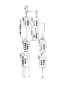
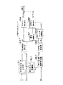
まず、第1制御例について図面を用いて詳しく説明すると、図2は、この第1制御例に係る電子制御ユニット24の機能ブロック図である。目標電流値決定部BL1が、操舵トルクセンサ21および車速センサ23によってそれぞれ検出された操舵トルクTおよび車速Vを用いて目標電流値テーブルを参照し、操舵トルクTおよび車速Vに応じて変化する目標電流値I*を決定する。この目標電流値テーブルは、電子制御ユニット24内のROMに予め記憶されており、図3に示すように、複数の代表的な車速値ごとに、操舵トルクTの増加に従って非線形増加する複数の目標電流値I*を記憶している。この目標電流値I*は、同一の操舵トルクTに対して、車速Vが低いほど大きい。なお、この目標電流値テーブルを利用するのに代えて、操舵トルクTおよび車速Vに応じて変化する目標電流値I*を関数により予め定義しておき、同関数を利用して目標電流値I*を計算するようにしてもよい。
a. First Control Example First, the first control example will be described in detail with reference to the drawings. FIG. 2 is a functional block diagram of the
この決定された目標電流値I*は、電流偏差演算部BL2に供給される。電流偏差演算部BL2は、電流センサ25aによって検出された実電流値Iも入力し、目標電流値I*から実電流値Iを減算することにより電流偏差ΔI(=I*−I)を計算して、積分演算部BL3およびPゲイン制御部BL4(すなわち比例項ゲイン制御部BL4)にそれぞれ供給する。積分演算部BL3は、時間経過に従って変化する電流偏差ΔIに積分演算を施して、Iゲイン制御部BL5(すなわち積分項ゲイン制御部BL5)に供給する。 The determined target current value I * is supplied to the current deviation calculation unit BL2. The current deviation calculation unit BL2 also inputs the actual current value I detected by the current sensor 25a, and calculates the current deviation ΔI (= I * −I) by subtracting the actual current value I from the target current value I *. Are supplied to the integral calculation unit BL3 and the P gain control unit BL4 (that is, the proportional term gain control unit BL4). The integral calculation unit BL3 performs an integral calculation on the current deviation ΔI that changes over time, and supplies it to the I gain control unit BL5 (that is, the integral term gain control unit BL5).
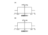
一方、PIゲイン設定部BL6(すなわち比例・積分制御ゲイン設定部BL6)は、操舵角センサ22によって検出された実操舵角θを用いて、Pゲインテーブル(すなわち比例項ゲインテーブル)およびIゲインテーブル(すなわち積分項ゲインテーブル)を参照し、実操舵角θに応じて変化するPゲインKpおよびIゲインKiを設定する。これらのPゲインテーブルおよびIゲインテーブルは、電子制御ユニット24のROM内に予め設けられており、図4(A)(B)に示すように、実操舵角θの絶対値|θ|が、所定の操舵舵角θ1(例えば、500度)以下であるとき大きな値となり、所定の操舵角θ1より大きいとき小さな値となるPゲインKpおよびIゲインKiを記憶している。なお、これらのPゲインテーブルおよびIゲインテーブルを利用するのに代えて、実操舵角θに応じて変化するPゲインKpおよびIゲインKiを関数により予め定義しておき、同関数を利用してPゲインKpおよびIゲインKiを計算するようにしてもよい。
On the other hand, the PI gain setting unit BL6 (that is, the proportional / integral control gain setting unit BL6) uses the actual steering angle θ detected by the
Pゲイン制御部BL4は、電流偏差演算部BL2から供給される電流偏差ΔIにPIゲイン設定部BL6から供給されるPゲインKpを乗算した比例制御値Kp・ΔIを加算部BL7に出力する。Iゲイン制御部BL4は、積分演算部BL3から供給される電流偏差積分値∫ΔIdtにPIゲイン設定部BL6から供給されるIゲインKiを乗算した積分制御値Ki・∫ΔIdtを加算部BL7に出力する。加算部BL7は、比例制御値Kp・ΔIと積分制御値Ki・∫ΔIdtを加算して、加算結果Kp・ΔI+Ki・∫ΔIdtを制御電圧値Eoとして駆動回路25に出力する。
The P gain control unit BL4 outputs a proportional control value Kp · ΔI obtained by multiplying the current deviation ΔI supplied from the current deviation calculation unit BL2 by the P gain Kp supplied from the PI gain setting unit BL6 to the addition unit BL7. The I gain control unit BL4 outputs an integral control value Ki · ∫ΔIdt obtained by multiplying the current deviation integral value ∫ΔIdt supplied from the integration calculation unit BL3 by the I gain Ki supplied from the PI gain setting unit BL6 to the addition unit BL7. To do. The adder BL7 adds the proportional control value Kp · ΔI and the integral control value Ki · ∫ΔIdt, and outputs the addition result Kp · ΔI + Ki · ∫ΔIdt to the
駆動回路25は、制御電圧値Eoに比例した駆動電流を電動モータ15に流して、電動モータ15の回転をフィードバック制御する。したがって、電動モータ15は回転して、前記制御電圧値Eoに比例した回転トルクを出力する。この電動モータ15の回転は、ボールねじ機構16に伝達され、ボールねじ機構16は電動モータ15の回転を減速するとともに直線運動に変換して、ラックバー14を軸線方向に駆動する。その結果、運転者による操舵ハンドル11の回動操作が電動モータ15によりアシストされ、左右前輪FW1,FW2は運転者による操舵力と電動モータ15によるアシスト力により操舵される。
The
したがって、運転者は、電動モータ15によるアシスト力によってアシストされながら、操舵ハンドル11を回動操作できる。この場合、実操舵角θが大きくなっても、目標電流値I*に応じて電動モータ15は駆動制御され、実操舵角θの大きな状態時に必要される電動モータ15に対する制御量が確保されるので、操舵フィーリングが悪化することはない。また、実操舵角θの絶対値|θ|が所定の操舵角θ1以下であれば、PゲインKpおよびIゲインKiは大きな値に設定される。なお、この大きな値に設定されたゲインKp,Kiを用いる結果、この第1制御例では、実操舵角θの絶対値|θ|が所定の操舵角θ1以内である限り、電動モータ15の制御応答性が高く保たれて、電動モータ15、ボールねじ機構16、ラックバー14などからなる操舵機構による異音の発生が抑制される。また、実操舵角θの絶対値|θ|が大きくなって所定の操舵角θ1を越えると、フィードバックゲインであるゲインKp,Kiが小さな値に変更される。そして、小さなゲインKp,Kiによって電動モータ15をフィードバック制御する結果、制御電圧値Eoの変動が大きくなっても、電動モータ15の出力トルクが変動し難くなるので、前記操舵機構の過補償に起因した異音の発生が抑制される。
Therefore, the driver can turn the steering handle 11 while being assisted by the assist force of the
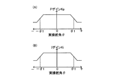
なお、前記第1制御例においては、実操舵角θの絶対値|θ|が所定の操舵角θ1を境に2値に変化するPゲインKpおよびIゲインKiを記憶したPゲインテーブルおよびIゲインテーブルを利用した。しかし、これらのテーブルに代えて、図5(A)(B)に示すように、実操舵角θの絶対値|θ|が所定の操舵角θ1を挟んで増加するに従って、大きな値から小さな値に徐々に変化するPゲインKpおよびIゲインKiを記憶したPゲインテーブルおよびIゲインテーブルを用いるようにしてもよい。これによれば、実操舵角θの変化に応じて滑らかに変化するPゲインKpおよびIゲインKiを用いてフィードバック制御され、フィードバックゲインの切り換えが滑らかに行われるので、上記第1制御例に比べて、運転者は操舵ハンドル11の回動操作に対して違和感を覚えることがなくなる。
In the first control example, the P gain table and the I gain storing the P gain Kp and the I gain Ki in which the absolute value | θ | of the actual steering angle θ changes to a binary value with the predetermined steering angle θ1 as a boundary. A table was used. However, instead of these tables, as shown in FIGS. 5A and 5B, as the absolute value | θ | of the actual steering angle θ increases with a predetermined steering angle θ1, the larger value becomes smaller. Alternatively, a P gain table and an I gain table in which the P gain Kp and the I gain Ki that change gradually may be used. According to this, feedback control is performed using the P gain Kp and the I gain Ki that smoothly change in accordance with the change in the actual steering angle θ, and the feedback gain is switched smoothly. Therefore, compared with the first control example. Thus, the driver does not feel uncomfortable with the turning operation of the
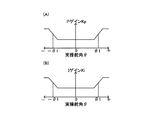
また、前記第1制御例およびその変形例においては、実操舵角θの絶対値|θ|が大きくなると、同絶対値|θ|が小さいときに比べて、PゲインKpおよびIゲインKiが小さな値となるようにした。しかし、図6(A)(B)に示すように、実操舵角θの絶対値|θ|が所定の操舵角θ1以下であるとき小さな値をなり、同絶対値|θ|が所定の操舵角θ1を越えると大きな値となるPゲインKpおよびIゲインKiを記憶したPゲインテーブルおよびIゲインテーブルを用いるようにしてもよい。また、この変形例においても、図7(A)(B)に示すように、実操舵角θの絶対値|θ|が所定の操舵角θ1を挟んで増加するに従って、小さな値から大きな値に徐々に変化するPゲインKpおよびIゲインKiを記憶したPゲインテーブルおよびIゲインテーブルを用いるようにしてもよい。 In the first control example and its modification, when the absolute value | θ | of the actual steering angle θ is increased, the P gain Kp and the I gain Ki are smaller than when the absolute value | θ | is small. It was made to become a value. However, as shown in FIGS. 6A and 6B, when the absolute value | θ | of the actual steering angle θ is equal to or smaller than the predetermined steering angle θ1, the absolute value | θ | A P gain table and an I gain table in which the P gain Kp and the I gain Ki that become large when the angle θ1 is exceeded may be used. Also in this modification, as shown in FIGS. 7A and 7B, the absolute value | θ | of the actual steering angle θ increases from a small value to a large value as the predetermined steering angle θ1 increases. A P gain table and an I gain table storing the gradually changing P gain Kp and I gain Ki may be used.
前記第1制御例の場合のように、電動モータ15の制御応答性が高く(すなわち周波数応答性が高く)、実操舵角θの絶対値|θ|が大きくない状態で、電動モータ15、ボールねじ機構16およびラックバー14からなる操舵機構に異音が発生しないように電動モータ15に対する制御がチューニングされていることがある。しかし、操舵アシスト装置の中には、実操舵角θの絶対値|θ|が大きくない範囲内において、電動モータ15の制御応答性を低くして(すなわち周波数応答性を低くして)前記操舵機構に異音が発生しないように、操舵機構の特性に合わせて電動モータ15に対する制御がチューニングされている場合もある。この場合には、実操舵角θの絶対値|θ|が大きくなると、操舵機構の作動に対して電動モータ15の出力トルクの応答遅れが顕著になる傾向にある。しかし、前記変形例においては、実操舵角θの絶対値|θ|が大きいときに、前記第1制御例とは逆にPゲインKpおよびIゲインKiが共に大きくなるので、電動モータ15の出力トルクの応答遅れが緩和されて、操舵機構内の異音の発生が抑制される。
As in the case of the first control example, the
さらに、上記実施形態においては、PゲインKpおよびIゲインKiの両方を用いて電動モータ15をフィードバック制御したが、これに代えて、PゲインKpおよびIゲインKiのうちのいずれか一方のみを用いて電動モータ15をフィードバック制御するようにしてもよい。また、後述する他の制御例においても、PゲインKpおよびIゲインKiの両方を用いて電動モータ15をフィードバック制御するようにした例について説明するが、これらの他の制御例においても、PゲインKpおよびIゲインKiのうちのいずれか一方のみを用いて電動モータ15をフィードバック制御するようにしてもよい。
Furthermore, in the above embodiment, the
b.第2制御例
次に、第2制御例について説明すると、この第2制御例に係る電子制御ユニット24の機能ブロック図は図8に示されている。この図8の機能ブロック図は、図2の機能ブロック図に対して、PIゲイン設定部BL6の前段に操舵角判定部BL8が追加されている。また、この図8のPIゲイン設定部BL6は前記図2の機能ブロック図のPIゲイン設定部BL6とは異なる機能を有するが、その他の部分に関しては図2の機能ブロック図の場合と同じであるので、前記第1制御例とは異なる部分についてのみ説明して、その他の部分に関しては説明を省略する。
b. Second Control Example Next, a second control example will be described. A functional block diagram of the
操舵角判定部BL8は、図9のステップS10〜S15からなる操舵角判定プログラムを所定の短時間ごとに繰り返し実行して、PゲインおよびIゲインの設定条件を決定するためのフラグFLGを“0”または“1”に設定する。すなわち、操舵角判定部BL8は、操舵角センサ22から実操舵角θを入力し、入力した実操舵角θの絶対値|θ|が所定の操舵角θ1以下であればフラグFLGを“0”に設定し、同絶対値|θ|が所定の操舵角θ1を越えるとフラグFLGを“1”に設定する。
The steering angle determination unit BL8 repeatedly executes the steering angle determination program including steps S10 to S15 in FIG. 9 every predetermined short time, and sets a flag FLG for determining the setting conditions for the P gain and the I gain to “0”. Set to “1” or “1”. That is, the steering angle determination unit BL8 inputs the actual steering angle θ from the
PIゲイン設定部BL6は、図10のステップS20〜S24からなるPIゲイン設定プログラムを所定の短時間ごとに繰り返し実行し、PゲインマップおよびIゲインマップをそれぞれ参照して、操舵角判定部BL8によって設定されたフラグFLGに応じてPゲインKpおよびIゲインKiを設定する。すなわち、PゲインマップおよびIゲインマップは図11に示されており、フラグFLGが“0”であれば、PゲインKpおよびIゲインKiは通常定数Kp1,Ki1に設定される。また、フラグFLGが“1”であれば、PゲインKpおよびIゲインKiは異音対応定数Kp2,Ki2に設定される。 The PI gain setting unit BL6 repeatedly executes the PI gain setting program consisting of steps S20 to S24 in FIG. 10 every predetermined short time, and refers to the P gain map and the I gain map, respectively, and determines the steering angle determination unit BL8. A P gain Kp and an I gain Ki are set according to the set flag FLG. That is, the P gain map and the I gain map are shown in FIG. 11. If the flag FLG is “0”, the P gain Kp and the I gain Ki are normally set to constants Kp1 and Ki1. If the flag FLG is “1”, the P gain Kp and the I gain Ki are set to the abnormal sound corresponding constants Kp2 and Ki2.
PゲインマップおよびIゲインマップにおいては、電動モータ15の制御応答性が高く、実操舵角θの絶対値|θ|が大きくない状態で、電動モータ15、ボールねじ機構16およびラックバー14からなる操舵機構に異音が発生しないように電動モータ15に対する制御がチューニングされている場合には、上記図4(A)(B)のゲインテーブルと同様に、異音対応定数Kp2,Ki2は通常定数Kp1,Ki1よりもそれぞれ小さな値に設定されている。一方、電動モータ15の制御応答性が低く、実操舵角θの絶対値|θ|が大きくない状態で、前記操舵機構に異音が発生しないように電動モータ15に対する制御がチューニングされている場合には、上記図6(A)(B)のゲインテーブルと同様に、異音対応定数Kp2,Ki2は通常定数Kp1,Ki1よりもそれぞれ大きな値に設定されている。なお、後述する各制御例においても、これらの定数Kp1,Ki1,Kp2,Ki2は用いられるようになっており、同各制御例においても、定数Kp1,Ki1,Kp2,Ki2は前述のように設定されているものとする。
In the P gain map and the I gain map, the control response of the
上記説明のように、この第2制御例においても、上記第1制御例の場合と同様に、実操舵角θの絶対値|θ|が大きくなると、PゲインKpおよびIゲインKiは通常定数Kp1,Ki1から異音対応定数Kp2,Ki2に切換えられる。したがって、この第2制御例によっても、上記第1制御例の場合と同様に、操舵フィーリングが実操舵角θが変化しても常に良好に保たれるとともに、ボールねじ機構16およびラックバー14からなる操舵機構内の異音の発生が実操舵角θが変化しても常に抑制される。
As described above, in the second control example, as in the case of the first control example, when the absolute value | θ | of the actual steering angle θ increases, the P gain Kp and the I gain Ki are normally constant Kp1. , Ki1 are switched to the abnormal sound corresponding constants Kp2, Ki2. Therefore, in the second control example, as in the case of the first control example, the steering feeling is always kept good even when the actual steering angle θ changes, and the
c.第3制御例
次に、第3制御例について説明すると、この第3制御例に係る電子制御ユニット24の機能ブロック図は図12に示されている。この図12の機能ブロック図は、第2制御例に関する図8の機能ブロック図の操舵角判定部BL8が操舵速度演算部BL9およびゲイン変更条件判定部BL10に変更されている。PIゲイン設定部BL6を含む他の部分に関しては、図8の機能ブロック図の場合と同じであるので、前記第2制御例とは異なる部分についてのみ説明して、その他の部分に関しては説明を省略する。
c. Third Control Example Next, a third control example will be described. A functional block diagram of the
操舵速度演算部BL9は、操舵角センサ22から入力した実操舵角θを時間微分して、操舵ハンドル11の操舵速度ω(左右前輪FW1,FW2の操舵速度および電動モータ15の回転速度と同等)を計算する。ゲイン変更条件判定部BL10は、図13のステップS30〜S36からなるゲイン変更条件判定プログラムを所定の短時間ごとに繰り返し実行して、実操舵角θおよび操舵速度ωに応じてフラグFLGを“0”または“1”に設定する。すなわち、ゲイン変更条件判定部BL10は、操舵角センサ22から実操舵角θを入力するとともに前記計算された操舵速度ωを入力し、入力した実操舵角θの絶対値|θ|が所定の操舵角θ1以下または入力した操舵速度ωの絶対値|ω|が所定の操舵速度ω1(例えば、100度/秒)以上であるとき、フラグFLGを“0”に設定する。また、実操舵角θの絶対値|θ|が所定の操舵角θ1よりも大きく、かつ操舵速度ωの絶対値|ω|が所定の操舵速度ω1未満であるとき、フラグFLGを“1”に設定する。
The steering speed calculation unit BL9 time-differentiates the actual steering angle θ input from the
このような第3制御例においては、第2制御例によるPゲインKpおよびIゲインKiの切換え制御に加えて、実操舵角θの絶対値|θ|が所定の操舵角θ1よりも大きくても、操舵速度ωの絶対値|ω|が所定の操舵速度ω1未満でない限り、PゲインKpおよびIゲインKiは通常定数Kp1,Ki1から異音対応定数Kp2,Ki2に切換えられない。その結果、操舵ハンドル11が大きく操舵されている状態でさらに急に操舵されても、電動モータ15の制御応答性が適切に制御され、操舵機構における異音および不具合の発生が防止される。
In such a third control example, in addition to the switching control of the P gain Kp and the I gain Ki in the second control example, even if the absolute value | θ | of the actual steering angle θ is larger than the predetermined steering angle θ1. Unless the absolute value | ω | of the steering speed ω is less than the predetermined steering speed ω1, the P gain Kp and the I gain Ki are not switched from the normal constants Kp1 and Ki1 to the abnormal sound corresponding constants Kp2 and Ki2. As a result, even when the
具体的には、電動モータ15の制御応答性が高く、実操舵角θの絶対値|θ|が大きくない状態で、操舵機構に異音が発生しないように電動モータ15に対する制御がチューニングされている場合には、前記絶対値|θ|が大きい状態で操舵ハンドル11が速く操舵されると、急激な電圧(電流)変化を必要とする場合があり、電動モータ15の制御応答性が悪いと、操舵機構に異音および不具合が発生する場合がある。しかし、この第3制御例によれば、このような場合には、PゲインKpおよびIゲインKiは通常定数Kp1,Ki1から異音対応定数Kp2,Ki2に切換えられないので、すなわち高い値から低い値に切換えられないので、電動モータ15の制御応答性は以前の高い状態に保たれ、操舵機構における異音または不具合の発生が防止される。
Specifically, the control for the
また、電動モータ15の制御応答性が低く、実操舵角θの絶対値|θ|が大きくない状態で、操舵機構に異音が発生しないように電動モータ15に対する制御がチューニングされている場合には、前記絶対値|θ|が大きい状態で操舵ハンドル11が速く操舵されると、急激な電圧(電流)変化を必要とする場合があり、電動モータ15の制御応答性を急に高くすると、操舵機構の応答性とのずれにより異音が発生し、またシステム異常に至る場合がある。しかし、このような場合には、PゲインKpおよびIゲインKiは通常定数Kp1,Ki1から異音対応定数Kp2,Ki2に切換えられないので、すなわち低い値から高い値に切換えられないので、電動モータ15の制御応答性が急激に過度に高くなることがなく、操舵機構における異音および不具合の発生が防止される。
In addition, when the control response of the
なお、この第3制御例において、実操舵角θおよび操舵速度ωに応じたPゲインKpおよびIゲインKiの変更制御に対してヒステリシス特性をもたせるように変形することも可能である。この変形例においては、ゲイン変更条件判定部BL10は、図13のゲイン変更条件判定プログラムに代えて、図14のゲイン変更条件判定プログラムを所定の短時間ごとに繰り返し実行する。 In the third control example, it is possible to modify the P gain Kp and the I gain Ki according to the actual steering angle θ and the steering speed ω so as to have hysteresis characteristics. In this modification, the gain change condition determination unit BL10 repeatedly executes the gain change condition determination program of FIG. 14 every predetermined short time instead of the gain change condition determination program of FIG.
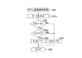
このゲイン変更条件判定プログラムにおいては、ゲイン変更条件判定部BL10は、ステップS40におけるプログラムの実行開始後、ステップS41にて実操舵角θおよび操舵速度ωを入力する。そして、ステップS42〜S46の処理によりエンド条件フラグEFLを実操舵角θの変化に応じて“0”または“1”に設定する。すなわち、図15(A)に示すように、エンド条件フラグEFLが“0”に設定されている状態では、実操舵角θの絶対値|θ|が所定の操舵角θ1(例えば、500度)よりも大きくなったときに初めてエンド条件フラグEFLを“1”に変更する。一方、エンド条件フラグEFLが“1”に設定されている状態では、実操舵角θの絶対値|θ|が前記操舵角θ1よりも小さな所定の操舵角θ2(例えば、490度)未満になったときに初めてエンド条件フラグEFLを“0”に変更する。 In the gain change condition determination program, the gain change condition determination unit BL10 inputs the actual steering angle θ and the steering speed ω in step S41 after the execution of the program in step S40 is started. Then, the end condition flag EFL is set to “0” or “1” according to the change of the actual steering angle θ by the processing of steps S42 to S46. That is, as shown in FIG. 15A, when the end condition flag EFL is set to “0”, the absolute value | θ | of the actual steering angle θ is a predetermined steering angle θ1 (for example, 500 degrees). The end condition flag EFL is changed to “1” for the first time when it becomes larger. On the other hand, when the end condition flag EFL is set to “1”, the absolute value | θ | of the actual steering angle θ is less than a predetermined steering angle θ2 (for example, 490 degrees) smaller than the steering angle θ1. The end condition flag EFL is changed to “0” for the first time.
また、ステップS48〜S52の処理により操舵速度条件フラグVFLを操舵速度ωの変化に応じて“0”または“1”に設定する。すなわち、図15(B)に示すように、操舵速度条件フラグVFLが“0”に設定されている状態では、操舵速度ωの絶対値|ω|が所定の操舵速度ω1(例えば、100度/秒)未満になったときに初めて操舵速度条件フラグVFLを“1”に変更する。一方、操舵速度条件フラグVFLが“1”に設定されている状態では、操舵速度ωの絶対値|ω|が前記操舵速度ω1よりも大きな所定の操舵速度ω2(例えば、200度/秒)よりも大きくなったときに初めて操舵速度条件フラグVFLを“0”に変更する。 Further, the steering speed condition flag VFL is set to “0” or “1” according to the change of the steering speed ω by the processing of steps S48 to S52. That is, as shown in FIG. 15B, in the state where the steering speed condition flag VFL is set to “0”, the absolute value | ω | of the steering speed ω is a predetermined steering speed ω1 (for example, 100 degrees / The steering speed condition flag VFL is changed to “1” for the first time when it becomes less than (second). On the other hand, in a state where the steering speed condition flag VFL is set to “1”, the absolute value | ω | of the steering speed ω is larger than a predetermined steering speed ω2 (for example, 200 degrees / second) larger than the steering speed ω1. For the first time, the steering speed condition flag VFL is changed to “0”.
そして、ステップS47,S53〜S55の処理により、エンド条件フラグEFLが“0”であり、または操舵速度条件フラグVFLが“0”であるとき、フラグFLGを“0”に設定する。また、エンド条件フラグEFLが“1”であり、かつ操舵速度条件フラグVFLが“1”であるとき、フラグFLGを“1”に設定する。そして、PIゲイン設定部BL6は、前記第3制御例と同様にして、このフラグFLGに従ってPゲインKpおよびIゲインKiを変更制御する。その結果、実操舵角θおよび操舵速度ωの変化に応じたPゲインKpおよびIゲインKiの変更制御に対してヒステリシス特性が付加される。 Then, the flag FLG is set to “0” when the end condition flag EFL is “0” or the steering speed condition flag VFL is “0” by the processes of steps S47 and S53 to S55. When the end condition flag EFL is “1” and the steering speed condition flag VFL is “1”, the flag FLG is set to “1”. Then, the PI gain setting unit BL6 controls to change the P gain Kp and the I gain Ki according to the flag FLG as in the third control example. As a result, a hysteresis characteristic is added to the change control of the P gain Kp and the I gain Ki according to changes in the actual steering angle θ and the steering speed ω.
この第3制御例の変形例によれば、実操舵角θおよび操舵速度ωの変化に対して、PゲインKpおよびIゲインKiの切換えの頻度が緩和される。その結果、PゲインKpおよびIゲインKiの切換え、すなわち電動モータ15への駆動電流の頻繁な切り換えが緩和されて、操舵機構における異音の発生がより良好に抑制される。
According to the modification of the third control example, the frequency of switching between the P gain Kp and the I gain Ki is reduced with respect to changes in the actual steering angle θ and the steering speed ω. As a result, the switching of the P gain Kp and the I gain Ki, that is, the frequent switching of the drive current to the
d.第4制御例
次に、第4制御例について説明すると、この第4制御例に係る電子制御ユニット24の機能ブロック図は図16に示されている。この図16の機能ブロック図は、第3制御例に関する図12の機能ブロック図の操舵速度演算部BL9を省略して、ゲイン変更条件判定部BL10には、操舵速度ωに代えて電流センサ25aによって検出された電動モータ15に流れる実電流値Iが入力されている。その他の部分に関しては、図12の機能ブロック図の場合と同じであるので、前記第3制御例とは異なる部分についてのみ説明して、その他の部分に関しては説明を省略する。
d. Fourth Control Example Next, a fourth control example will be described. A functional block diagram of the
ゲイン変更条件判定部BL10は、図13のステップS31,S33の処理をステップS31a,S33aの処理に変更した図17のステップS30〜S36からなるゲイン変更条件判定プログラムを所定の短時間ごとに繰り返し実行する。ステップS31aにおいては、前記第3制御例の操舵速度ωに代えて、電流センサ25aによって検出された実電流値Iを入力する。ステップS33aにおいては、実電流値Iの絶対値|I|が所定の電流値I1(例えば、30A)よりも大きいか否かを判定する。なお、この所定の電流値I1は、車速Vがほぼ10km/hである状態で、操舵ハンドル11が操舵角±500度程度に操舵される際(PゲインKpおよびIゲインKiの切換えが行われる際)に電動モータ15に流れる電流値である。
The gain change condition determination unit BL10 repeatedly executes the gain change condition determination program including steps S30 to S36 in FIG. 17 in which the processes in steps S31 and S33 in FIG. 13 are changed to the processes in steps S31a and S33a every predetermined short time. To do. In step S31a, the actual current value I detected by the current sensor 25a is input instead of the steering speed ω in the third control example. In step S33a, it is determined whether or not the absolute value | I | of the actual current value I is larger than a predetermined current value I1 (for example, 30 A). The predetermined current value I1 is obtained when the
そして、この図17のゲイン変更条件判定プログラムの実行により、実操舵角θの絶対値|θ|が所定の操舵角θ1以下または実電流値Iの絶対値|I|が所定の電流値I1以下であるとき、フラグFLGを“0”に設定する。また、実操舵角θの絶対値|θ|が所定の操舵角θ1よりも大きく、かつ実電流値Iの絶対値|I|が所定の電流値I1よりも大きいとき、フラグFLGを“1”に設定する。 Then, the absolute value | θ | of the actual steering angle θ is equal to or smaller than the predetermined steering angle θ1 or the absolute value | I | of the actual current value I is equal to or smaller than the predetermined current value I1 by executing the gain change condition determination program of FIG. When this is the case, the flag FLG is set to “0”. When the absolute value | θ | of the actual steering angle θ is larger than the predetermined steering angle θ1 and the absolute value | I | of the actual current value I is larger than the predetermined current value I1, the flag FLG is set to “1”. Set to.
このような第4制御例においては、第2制御例によるPゲインKpおよびIゲインKiの切換え制御に加えて、実操舵角θの絶対値|θ|が所定の操舵角θ1より大きくても、実電流値Iの絶対値|I|が所定の電流値I1よりも大きくならない限り、PゲインKpおよびIゲインKiは通常定数Kp1,Ki1から異音対応定数Kp2,Ki2に切換えられない。言い換えれば、実操舵角θの絶対値|θ|が所定の操舵角θ1程度になっても、車速Vが高ければ、実電流値Iの絶対値|I|は大きくならないので(図3参照)、PゲインKpおよびIゲインKiは通常定数Kp1,Ki1から異音対応定数Kp2,Ki2に切換えられない。その結果、操舵ハンドル11が大きく操舵される車両の停止時または極低速時に合わせて、操舵機構から異音が発生しないように通常定数Kp1,Ki1および異音対応定数Kp2,Ki2を設定しても、高速走行時にPゲインKpおよびIゲインKiが通常定数Kp1,Ki1から異音対応定数Kp2,Ki2に切換えられることがなくなり、操舵フィーリングの悪化を防止できる。 In such a fourth control example, in addition to the switching control of the P gain Kp and the I gain Ki in the second control example, even if the absolute value | θ | of the actual steering angle θ is larger than the predetermined steering angle θ1, Unless the absolute value | I | of the actual current value I is larger than the predetermined current value I1, the P gain Kp and the I gain Ki are not switched from the normal constants Kp1 and Ki1 to the abnormal sound corresponding constants Kp2 and Ki2. In other words, even if the absolute value | θ | of the actual steering angle θ is about the predetermined steering angle θ1, the absolute value | I | of the actual current value I does not increase if the vehicle speed V is high (see FIG. 3). The P gain Kp and the I gain Ki cannot be switched from the normal constants Kp1 and Ki1 to the abnormal sound corresponding constants Kp2 and Ki2. As a result, the normal constants Kp1 and Ki1 and the abnormal noise corresponding constants Kp2 and Ki2 are set so that no abnormal noise is generated from the steering mechanism when the vehicle on which the steering handle 11 is largely steered is stopped or at an extremely low speed. The P gain Kp and the I gain Ki are not switched from the normal constants Kp1 and Ki1 to the abnormal sound corresponding constants Kp2 and Ki2 during high-speed traveling, and the steering feeling can be prevented from deteriorating.
なお、この第4制御例において、実操舵角θおよび実電流値Iに応じたPゲインKpおよびIゲインKiの変更制御に対してヒステリシス特性をもたせるように変形することも可能である。この変形例においても、ゲイン変更条件判定部BL10は、図17のゲイン変更条件判定プログラムに代えて、図14のゲイン変更条件判定プログラムを変形したプログラムを所定の短時間ごとに繰り返し実行する。 In the fourth control example, it is possible to modify the P gain Kp and the I gain Ki according to the actual steering angle θ and the actual current value I so as to have a hysteresis characteristic. Also in this modification, the gain change condition determination unit BL10 repeatedly executes a program obtained by modifying the gain change condition determination program in FIG. 14 every predetermined short time instead of the gain change condition determination program in FIG.
図14のゲイン変更条件判定プログラムを変形したプログラムにおいては、ステップS41にて操舵速度ωに代えて実電流値Iを入力するとともに、ステップS49の判定処理を図17のステップS33aの判定処理に変更する。また、ステップS50の判定処理を、実電流値Iの絶対値|I|が所定の電流値I1よりも小さな所定の電流値I2未満であるかを判定する処理に変更して、実電流値Iの絶対値|I|が所定の電流値I2未満であればプログラムをステップS52に進め、実電流値Iの絶対値|I|が所定の電流値I2以上であればプログラムをステップS53に進めるようにすればよい。なお、この場合の上記操舵速度条件フラグVFLは、電流条件フラグVFLと読み替えるものとする。 In a program obtained by modifying the gain change condition determination program in FIG. 14, the actual current value I is input instead of the steering speed ω in step S41, and the determination process in step S49 is changed to the determination process in step S33a in FIG. To do. In addition, the determination process of step S50 is changed to a process of determining whether the absolute value | I | of the actual current value I is less than a predetermined current value I2 that is smaller than the predetermined current value I1. If the absolute value | I | of the current value is less than the predetermined current value I2, the program proceeds to step S52. If the absolute value | I | of the actual current value I is equal to or greater than the predetermined current value I2, the program proceeds to step S53. You can do it. In this case, the steering speed condition flag VFL is read as a current condition flag VFL.
その結果、この第4制御例の変形例によっても、実操舵角θおよび実電流値Iの変化に対して、PゲインKpおよびIゲインKiの切換えの頻度が緩和される。したがって、PゲインKpおよびIゲインKiの切換え、すなわち電動モータ15への駆動電流の頻繁な切り換えが緩和されて、操舵機構における異音の発生がより良好に抑制される。
As a result, according to the modification of the fourth control example, the frequency of switching between the P gain Kp and the I gain Ki is reduced with respect to changes in the actual steering angle θ and the actual current value I. Therefore, the switching of the P gain Kp and the I gain Ki, that is, the frequent switching of the drive current to the
なお、前記第4実施形態およびその変形例においては、実電流値IをPゲインKpおよびIゲインKiの切換えの制御に利用した。しかし、この実電流値Iは電動モータ15に流れる電流を表していればよく、目標電流値I*と実電流値Iはほぼ等しいので、実電流値Iに代えて目標電流値I*を利用するようにしてもよい。
In the fourth embodiment and its modifications, the actual current value I is used to control switching between the P gain Kp and the I gain Ki. However, the actual current value I only needs to represent the current flowing through the
e.第5制御例
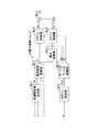
次に、第5制御例について説明すると、この第5制御例に係る電子制御ユニット24の機能ブロック図は図18に示されている。この図18の機能ブロック図は、第3制御例に関する図12の機能ブロック図の操舵速度演算部BL9に代えて電流変化率計算部BL11を用い、ゲイン変更条件判定部BL10には、操舵速度ωに代えて電流変化率計算部BL11によって計算された電流変化率Irtが入力されている。その他の部分に関しては、図12の機能ブロック図の場合と同じであるので、前記第3制御例とは異なる部分についてのみ説明して、その他の部分に関しては説明を省略する。
e. Fifth Control Example Next, a fifth control example will be described. A functional block diagram of the
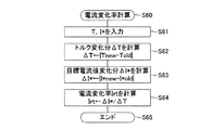
電流変化率計算部BL11は、図19のステップS60〜S65からなる電流変化率計算プログラムを所定の短時間ごとに繰り返し実行して、操舵トルクTの変化率に対する目標電流値I*の変化率の比の値を電流変化率Irtとして計算する。具体的には、ステップS61にて、操舵トルクセンサ21によって検出された操舵トルクTおよび目標電流値決定部BL1によって決定された目標電流値I*を入力する。次に、ステップS62にて、今回処理時の操舵トルクTnewから前回処理時の操舵トルクToldを減算し、減算結果Tnew−Toldの絶対値|Tnew−Told|をトルク変化分ΔTとして計算する。次に、ステップS63にて、今回処理時の目標電流値I*newから前回処理時の目標電流値I*oldを減算し、減算結果I*new−I*oldの絶対値|I*new−I*old|を目標電流値変化分ΔI*として計算する。そして、ステップS64にて、目標電流値変化分ΔI*をトルク変化分ΔTで除算して、電流変化率Irtを計算する。
The current change rate calculation unit BL11 repeatedly executes the current change rate calculation program including steps S60 to S65 of FIG. 19 every predetermined short time, and calculates the change rate of the target current value I * with respect to the change rate of the steering torque T. The ratio value is calculated as the current change rate Irt. Specifically, in step S61, the steering torque T detected by the
ゲイン変更条件判定部BL10は、図13のステップS31,S33の処理をステップS31b,S33bの処理に変更した図20のステップS30〜S36からなるゲイン変更条件判定プログラムを所定の短時間ごとに繰り返し実行する。ステップS31bにおいては、前記第3制御例の操舵速度ωに代えて、電流変化率計算部BL11によって計算された電流変化率Irtを入力する。ステップS33bにおいては、電流変化率Irtが所定の電流変化率Irt1(例えば、200A/Nm)よりも大きいか否かを判定する。 The gain change condition determination unit BL10 repeatedly executes the gain change condition determination program including steps S30 to S36 in FIG. 20 in which the processes in steps S31 and S33 in FIG. 13 are changed to the processes in steps S31b and S33b every predetermined short time. To do. In step S31b, the current change rate Irt calculated by the current change rate calculation unit BL11 is input instead of the steering speed ω of the third control example. In step S33b, it is determined whether or not the current change rate Irt is larger than a predetermined current change rate Irt1 (for example, 200 A / Nm).
そして、この図20のゲイン変更条件判定プログラムの実行により、実操舵角θの絶対値|θ|が所定の操舵角θ1以下または電流変化率Irtが所定の電流変化率Irt1以下であるとき、フラグFLGを“0”に設定する。また、実操舵角θの絶対値|θ|が所定の操舵角θ1よりも大きく、かつ電流変化率Irtが所定の電流変化率Irt1よりも大きいとき、フラグFLGを“1”に設定する。 When the absolute value | θ | of the actual steering angle θ is equal to or smaller than the predetermined steering angle θ1 or the current change rate Irt is equal to or smaller than the predetermined current change rate Irt1 by executing the gain change condition determination program of FIG. Set FLG to “0”. When the absolute value | θ | of the actual steering angle θ is larger than the predetermined steering angle θ1 and the current change rate Irt is larger than the predetermined current change rate Irt1, the flag FLG is set to “1”.
このような第5制御例においては、第2制御例によるPゲインKpおよびIゲインKiの切換え制御に加えて、実操舵角θの絶対値|θ|が所定の操舵角θ1より大きくても、電流変化率Irtが所定の電流変化率Irt1よりも大きくならない限り、PゲインKpおよびIゲインKiは通常定数Kp1,Ki1から異音対応定数Kp2,Ki2に切換えられない。この電流変化率Irtは、必要なアシスト力に対する電動モータ15によって発生されるトルク変動の大きさ、すなわちその値の増加により異音が発生し易い状況を示している。そして、この電流変化率Irtが小さいときには、PゲインKpおよびIゲインKiは通常定数Kp1,Ki1から異音対応定数Kp2,Ki2への切換えが禁止され、電流変化率Irtが大きくなると前記PゲインKpおよびIゲインKiの切り換えが許容される。その結果、異音が発生し易い状況下で、PゲインKpおよびIゲインKiは通常定数Kp1,Ki1から異音対応定数Kp2,Ki2へ切換えられ易くなるための、異音の低減と良好な操舵フィーリングの両立が可能となる。
In the fifth control example, in addition to the switching control of the P gain Kp and the I gain Ki in the second control example, even if the absolute value | θ | of the actual steering angle θ is larger than the predetermined steering angle θ1, Unless the current change rate Irt becomes larger than the predetermined current change rate Irt1, the P gain Kp and the I gain Ki cannot be switched from the normal constants Kp1 and Ki1 to the abnormal sound corresponding constants Kp2 and Ki2. This current change rate Irt indicates a situation in which abnormal noise is likely to occur due to the magnitude of the torque fluctuation generated by the
なお、この第5制御例において、実操舵角θおよび実電流値Iに応じたPゲインKpおよびIゲインKiの変更制御に対してヒステリシス特性をもたせるように変形することも可能である。この変形例においても、ゲイン変更条件判定部BL10は、図20のゲイン変更条件判定プログラムに代えて、図14のゲイン変更条件判定プログラムを変形したプログラムを所定の短時間ごとに繰り返し実行する。 In the fifth control example, it is also possible to modify the P gain Kp and the I gain Ki according to the actual steering angle θ and the actual current value I so as to have a hysteresis characteristic. Also in this modification, the gain change condition determination unit BL10 repeatedly executes a program obtained by modifying the gain change condition determination program in FIG. 14 every predetermined short time instead of the gain change condition determination program in FIG.
図14のゲイン変更条件判定プログラムを変形したプログラムにおいては、ステップS41にて操舵速度ωに代えて電流変化率Irtを入力するとともに、ステップS49の判定処理を図20のステップS33bの判定処理に変更する。また、ステップS50の判定処理を、電流変化率Irtが所定の電流変化率Irt1よりも小さな所定の電流変化率Irt2未満であるかを判定する処理に変更して、電流変化率Irtが所定の電流変化率Irt2未満であればプログラムをステップS52に進め、電流変化率Irtが所定の電流変化率Irt2以上であればプログラムをステップS53に進めるようにすればよい。なお、この場合の上記操舵速度条件フラグVFLは、電流変化率条件フラグVFLと読み替えるものとする。 In a program obtained by modifying the gain change condition determination program in FIG. 14, the current change rate Irt is input instead of the steering speed ω in step S41, and the determination process in step S49 is changed to the determination process in step S33b in FIG. To do. In addition, the determination process in step S50 is changed to a process for determining whether the current change rate Irt is less than a predetermined current change rate Irt2 smaller than the predetermined current change rate Irt1, and the current change rate Irt is a predetermined current. If the change rate is less than Irt2, the program proceeds to step S52, and if the current change rate Irt is equal to or greater than the predetermined current change rate Irt2, the program may be advanced to step S53. In this case, the steering speed condition flag VFL is read as the current change rate condition flag VFL.
その結果、この第5制御例の変形例によっても、実操舵角θおよび電流変化率Irtの変化に対して、PゲインKpおよびIゲインKiの切換えの頻度が緩和される。したがって、PゲインKpおよびIゲインKiの切換え、すなわち電動モータ15への駆動電流の頻繁な切り換えが緩和されて、操舵機構における異音の発生がより良好に抑制される。
As a result, according to the modification of the fifth control example, the frequency of switching between the P gain Kp and the I gain Ki is reduced with respect to the change in the actual steering angle θ and the current change rate Irt. Therefore, the switching of the P gain Kp and the I gain Ki, that is, the frequent switching of the drive current to the
なお、前記第5実施形態およびその変形例においては、目標電流値I*を電流変化率Irtの計算に利用した。しかし、この目標電流値I*は電動モータ15に流れる電流を表していればよく、目標電流値I*と実電流値Iはほぼ等しいので、目標電流値I*に代えて実電流値Iを利用するようにしてもよい。
In the fifth embodiment and its modifications, the target current value I * is used for calculating the current change rate Irt. However, the target current value I * only needs to represent the current flowing through the
f.第6制御例
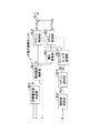
次に、第6制御例について説明すると、この第6制御例に係る電子制御ユニット24の機能ブロック図は図21に示されている。この図21の機能ブロック図は、第3制御例に関する図12の機能ブロック図の操舵速度演算部BL9を省略して、ゲイン変更条件判定部BL10には、操舵速度ωに代えて車速センサ23によって検出された車速Vが入力されている。その他の部分に関しては、図12の機能ブロック図の場合と同じであるので、前記第3制御例とは異なる部分についてのみ説明して、その他の部分に関しては説明を省略する。
f. Sixth Control Example Next, a sixth control example will be described. A functional block diagram of the
ゲイン変更条件判定部BL10は、図13のステップS31,S33の処理をステップS31c,S33cの処理に変更した図22のステップS30〜S36からなるゲイン変更条件判定プログラムを所定の短時間ごとに繰り返し実行する。ステップS31cにおいては、前記第3制御例の操舵速度ωに代えて、車速センサ23によって検出された車速Vを入力する。ステップS33cにおいては、車速Vが所定の車速V1(例えば、10km/h)よりも小さいか否かを判定する。
The gain change condition determination unit BL10 repeatedly executes the gain change condition determination program including steps S30 to S36 in FIG. 22 in which the processes in steps S31 and S33 in FIG. 13 are changed to the processes in steps S31c and S33c every predetermined short time. To do. In step S31c, the vehicle speed V detected by the
そして、この図22のゲイン変更条件判定プログラムの実行により、実操舵角θの絶対値|θ|が所定の操舵角θ1以下または車速Vが所定の車速V1以上であるとき、フラグFLGを“0”に設定する。また、実操舵角θの絶対値|θ|が所定の操舵角θ1よりも大きく、かつ車速Vが所定の車速V1よりも小さいとき、フラグFLGを“1”に設定する。 When the absolute value | θ | of the actual steering angle θ is equal to or smaller than the predetermined steering angle θ1 or the vehicle speed V is equal to or higher than the predetermined vehicle speed V1 by executing the gain change condition determination program shown in FIG. Set to "". When the absolute value | θ | of the actual steering angle θ is larger than the predetermined steering angle θ1 and the vehicle speed V is smaller than the predetermined vehicle speed V1, the flag FLG is set to “1”.
このような第6制御例においては、第2制御例によるPゲインKpおよびIゲインKiの切換え制御に加えて、実操舵角θの絶対値|θ|が所定の操舵角θ1より大きくても、車速Vが所定の車速V1以下でない限り、PゲインKpおよびIゲインKiは通常定数Kp1,Ki1から異音対応定数Kp2,Ki2に切換えられない。その結果、操舵ハンドル11が大きく操舵される車両の停止時または極低速時に合わせて、操舵機構から異音が発生しないように通常定数Kp1,Ki1および異音対応定数Kp2,Ki2を設定しても、高速走行時にPゲインKpおよびIゲインKiが通常定数Kp1,Ki1から異音対応定数Kp2,Ki2に切換えられることなくなり、操舵フィーリングの悪化を防止できる。 In such a sixth control example, in addition to the switching control of the P gain Kp and the I gain Ki in the second control example, even if the absolute value | θ | of the actual steering angle θ is larger than the predetermined steering angle θ1, Unless the vehicle speed V is lower than the predetermined vehicle speed V1, the P gain Kp and the I gain Ki are not switched from the normal constants Kp1, Ki1 to the abnormal sound corresponding constants Kp2, Ki2. As a result, the normal constants Kp1 and Ki1 and the abnormal noise corresponding constants Kp2 and Ki2 are set so that no abnormal noise is generated from the steering mechanism when the vehicle on which the steering handle 11 is largely steered is stopped or at an extremely low speed. The P gain Kp and the I gain Ki are not switched from the normal constants Kp1 and Ki1 to the abnormal noise corresponding constants Kp2 and Ki2 during high speed running, and the steering feeling can be prevented from deteriorating.
なお、この第6制御例において、実操舵角θおよび車速Vに応じたPゲインKpおよびIゲインKiの変更制御に対してヒステリシス特性をもたせるように変形することも可能である。この変形例においても、ゲイン変更条件判定部BL10は、図22のゲイン変更条件判定プログラムに代えて、図14のゲイン変更条件判定プログラムを変形したプログラムを所定の短時間ごとに繰り返し実行する。 In the sixth control example, it is possible to modify the P gain Kp and the I gain Ki according to the actual steering angle θ and the vehicle speed V so as to have a hysteresis characteristic. Also in this modification, the gain change condition determination unit BL10 repeatedly executes a program obtained by modifying the gain change condition determination program in FIG. 14 every predetermined short time instead of the gain change condition determination program in FIG.
図14のゲイン変更条件判定プログラムを変形したプログラムにおいては、ステップS41にて操舵速度ωに代えて車速Vを入力するとともに、ステップS49の判定処理を図22のステップS33cの判定処理に変更する。また、ステップS50の判定処理を、車速Vが所定の車速V1よりも大きな所定の車速V2(例えば、20km/h)よりも大きいかを判定する処理に変更して、車速Vが所定の車速V2よりも大きければプログラムをステップS52に進め、車速Vが所定の車速V2以下であればプログラムをステップS53に進めるようにすればよい。なお、この場合の上記操舵速度条件フラグVFLは、車速条件フラグVFLと読み替えるものとする。 In a program obtained by modifying the gain change condition determination program in FIG. 14, the vehicle speed V is input instead of the steering speed ω in step S41, and the determination process in step S49 is changed to the determination process in step S33c in FIG. Further, the determination process in step S50 is changed to a process for determining whether the vehicle speed V is greater than a predetermined vehicle speed V2 (for example, 20 km / h) greater than the predetermined vehicle speed V1, and the vehicle speed V is set to the predetermined vehicle speed V2. If the vehicle speed V is greater than that, the program proceeds to step S52, and if the vehicle speed V is equal to or lower than the predetermined vehicle speed V2, the program may proceed to step S53. In this case, the steering speed condition flag VFL is read as a vehicle speed condition flag VFL.
その結果、この第6制御例の変形例によっても、実操舵角θおよび車速Vの変化に対して、PゲインKpおよびIゲインKiの切換えの頻度が緩和される。したがって、PゲインKpおよびIゲインKiの切換え、すなわち電動モータ15への駆動電流の頻繁な切り換えが緩和されて、操舵機構における異音の発生がより良好に抑制される。
As a result, according to the modification of the sixth control example, the frequency of switching between the P gain Kp and the I gain Ki is reduced with respect to changes in the actual steering angle θ and the vehicle speed V. Therefore, the switching of the P gain Kp and the I gain Ki, that is, the frequent switching of the drive current to the
g.その他の変形例
上記実施形態のその他の変形例について図面を用いて説明すると、図23ないし図28は上記第1ないし第6制御例の変形例に係る機能ブロックを示している。これらの各機能ブロック図においては、図2、図8、図12、図16、図18および図21に示した第1ないし第6制御例の機能ブロックの各PIゲイン設定部BL6の後段にローパスフィルタ処理部BL12がそれぞれ接続されている。これらのローパスフィルタ処理部BL12は、PIゲイン設定部BL6に設定されるPゲインKpおよびIゲインKiを順次入力して、入力したこれらのPゲインKpおよびIゲインKiにそれぞれローパルフィルタ処理を施してPゲイン制御部BL4およびIゲイン制御部BL5にそれぞれ出力する。
g. Other Modifications Other modifications of the above embodiment will be described with reference to the drawings. FIGS. 23 to 28 show functional blocks according to modifications of the first to sixth control examples. In each of these functional block diagrams, a low pass is provided after the PI gain setting unit BL6 of the functional blocks of the first to sixth control examples shown in FIGS. 2, 8, 12, 16, 18, and 21. Filter processing units BL12 are connected to each other. These low-pass filter processing units BL12 sequentially input the P gain Kp and I gain Ki set in the PI gain setting unit BL6, and perform a low-pass filter process on the input P gain Kp and I gain Ki, respectively. Output to the P gain controller BL4 and the I gain controller BL5, respectively.
これによれば、電流偏差ΔIおよびその積分値∫ΔIdtに乗算されるPゲインKpおよびIゲインKiがなまされ、PゲインKpおよびIゲインKiが切換えられても、制御電圧値Eoが滑らかに変化するとともに電動モータ15に流れる駆動電流も滑らかに変化する。したがって、PゲインKpおよびIゲインKiが切換えられても、電動モータ15による操舵アシスト力は滑らかに変化し、運転者は操舵ハンドル11の回動操作に違和感を覚えなくなる。
According to this, the P gain Kp and the I gain Ki multiplied by the current deviation ΔI and its integral value ΔΔdt are smoothed, and the control voltage value Eo becomes smooth even when the P gain Kp and the I gain Ki are switched. As it changes, the drive current flowing through the
さらに、本発明は上記実施形態およびその変形例に限定されることなく、本発明の範囲内において種々の変形例を採用することができる。 Furthermore, the present invention is not limited to the above-described embodiment and its modifications, and various modifications can be employed within the scope of the present invention.
11…操舵ハンドル、12…ステアリングシャフト、13…ピニオンギヤ、14…ラックバー、15…電動モータ、16…ボールねじ機構、21…操舵トルクセンサ、22…操舵角センサ、23…車速センサ、24…電子制御ユニット、25…駆動回路、25a…電流センサ
DESCRIPTION OF
Claims (13)
前記電動モータの目標制御量と前記電動モータの実制御量との差に応じた制御信号のゲインを制御して前記電動モータに供給するゲイン制御部と、
操舵ハンドルの操舵角を検出する操舵角検出手段と、
前記操舵角検出手段によって検出された操舵角が大きいとき、同操舵角が小さいときに比べて前記制御信号のゲインを大きくなる側に変更して、前記フィードバック制御における応答性が低いために発生する異音を減少させるゲイン変更手段とを設けたことを特徴とする車両の操舵アシスト装置。 An electric motor that applies assist force to steering of the steered wheels by turning the steering wheel, and feedback control is performed so that the actual control amount of the electric motor is fed back and the electric motor operates according to the target control amount In the vehicle steering assist device,
A gain control unit that controls the gain of a control signal according to the difference between the target control amount of the electric motor and the actual control amount of the electric motor and supplies the gain to the electric motor;
Steering angle detection means for detecting the steering angle of the steering wheel;
When the steering angle detected by the steering angle detection means is large, the gain of the control signal is changed to be larger than when the steering angle is small, and this occurs because the responsiveness in the feedback control is low. A vehicle steering assist device, comprising: a gain changing means for reducing abnormal noise .
前記ゲイン制御部は、前記電動モータの目標制御量と前記電動モータの実制御量との差に比例した制御信号、および前記電動モータの目標制御量と前記電動モータの実制御量との差を積分した制御信号のうちの少なくともいずれか一方の制御信号のゲインを制御する車両の操舵アシスト装置。 The vehicle steering assist device according to claim 1,
The gain control unit calculates a control signal proportional to a difference between the target control amount of the electric motor and the actual control amount of the electric motor, and a difference between the target control amount of the electric motor and the actual control amount of the electric motor. A vehicle steering assist device that controls the gain of at least one of the integrated control signals .
前記電動モータの目標制御量は、前記電動モータに流される目標電流値であり、かつ
前記電動モータの実制御量は、電流センサによって検出される前記電動モータに流れている実電流値である車両の操舵アシスト装置 In the steering assist device for a vehicle according to claim 1 or 2 ,
A vehicle in which the target control amount of the electric motor is a target current value passed through the electric motor, and the actual control amount of the electric motor is a real current value flowing through the electric motor detected by a current sensor. Steering assist device
操舵ハンドルに付与される操舵トルクを検出する操舵トルク検出手段と、
車速を検出する車速検出手段と、
前記検出された操舵トルクおよび車速に応じて前記電動モータの目標制御量を決定する目標制御量決定手段とを備えた車両の操舵アシスト装置。 The steering assist device for a vehicle according to any one of claims 1 to 3 , further comprising a steering torque detecting means for detecting a steering torque applied to the steering handle,
Vehicle speed detection means for detecting the vehicle speed;
A vehicle steering assist device, comprising: a target control amount determining unit that determines a target control amount of the electric motor according to the detected steering torque and vehicle speed.
前記電動モータの目標制御量と前記電動モータの実制御量との差に応じた制御信号のゲインを制御して前記電動モータに供給するゲイン制御部と、
操舵ハンドルの操舵角を検出する操舵角検出手段と、
前記操舵角検出手段によって検出された操舵角が所定操舵角よりも大きくなると、前記制御信号のゲインを第1のゲインから第2のゲインに変更するゲイン変更手段と、
操舵ハンドルの操舵速度を検出する操舵速度検出手段と、
前記操舵速度検出手段によって検出された操舵速度が所定操舵速度よりも小さいとき前記ゲイン変更手段による制御信号のゲインの変更を許容し、同検出された操舵速度が前記所定操舵速度以上であるとき前記ゲイン変更手段による制御信号のゲインの変更を禁止するゲイン変更制御手段とを設けた車両の操舵アシスト装置。 An electric motor that applies assist force to steering of the steered wheels by turning the steering wheel, and feedback control is performed so that the actual control amount of the electric motor is fed back and the electric motor operates according to the target control amount In the vehicle steering assist device,
A gain control unit that controls the gain of a control signal according to the difference between the target control amount of the electric motor and the actual control amount of the electric motor and supplies the gain to the electric motor;
Steering angle detection means for detecting the steering angle of the steering wheel;
Wherein the steering angle detected by the steering angle detection means is greater than a predetermined steering angle, a gain changing means for changing the gain of the control signal from the first gain to a second gain,
Steering speed detection means for detecting the steering speed of the steering wheel;
When the steering speed detected by the steering speed detecting means is smaller than a predetermined steering speed, the gain changing means allows the gain of the control signal to be changed, and when the detected steering speed is equal to or higher than the predetermined steering speed, A vehicle steering assist device provided with a gain change control means for prohibiting a gain change means from changing a gain of a control signal .
前記操舵角検出手段によって検出された操舵角および前記操舵速度検出手段によって検出された操舵速度の変化に応じた、前記ゲイン変更手段および前記ゲイン変更制御手段による制御信号のゲインの変更制御に対して、ヒステリシス特性をもたせた車両の操舵アシスト装置。 In the vehicle steering assist device according to claim 5 ,
With respect to the change control of the gain of the control signal by the gain change means and the gain change control means according to the change of the steering angle detected by the steering angle detection means and the steering speed detected by the steering speed detection means. A steering assist device for a vehicle with hysteresis characteristics.
操舵ハンドルに付与される操舵トルクを検出する操舵トルク検出手段と、
車速を検出する車速検出手段と、
前記検出された操舵トルクおよび車速に応じて前記電動モータの目標電流値を決定する目標電流値決定手段であって、前記検出された車速の増加に従って減少する前記電動モータの目標電流値を決定する目標電流値決定手段と、
前記電動モータの目標電流値と前記電動モータの実電流値との差に応じた制御信号のゲインを制御して前記電動モータに供給するゲイン制御部と、
操舵ハンドルの操舵角を検出する操舵角検出手段と、
前記操舵角検出手段によって検出された操舵角が所定操舵角よりも大きくなると、前記制御信号のゲインを第1のゲインから第2のゲインに変更するゲイン変更手段と、
前記電動モータに流れる電流が所定電流よりも大きいとき前記ゲイン変更手段による制御信号のゲインの変更を許容し、同電動モータに流れる電流が前記所定電流以下であるとき前記ゲイン変更手段による制御信号のゲインの変更を禁止するゲイン変更制御手段とを設けた車両の操舵アシスト装置。 An electric motor that applies assist force to steering of the steered wheels by turning the steering wheel, and feedback control is performed so that the actual current value of the electric motor is fed back and the electric motor operates according to the target current value In the vehicle steering assist device,
Steering torque detection means for detecting steering torque applied to the steering wheel;
Vehicle speed detection means for detecting the vehicle speed;
Target current value determining means for determining a target current value of the electric motor according to the detected steering torque and vehicle speed, and determining a target current value of the electric motor that decreases as the detected vehicle speed increases. A target current value determining means;
A gain control unit that controls the gain of a control signal according to the difference between the target current value of the electric motor and the actual current value of the electric motor, and supplies the control signal to the electric motor;
Steering angle detection means for detecting the steering angle of the steering wheel;
Wherein the steering angle detected by the steering angle detection means is greater than a predetermined steering angle, a gain changing means for changing the gain of the control signal from the first gain to a second gain,
The current flowing through the electric motor is allowed to change the gain of the control signal by the gain changing means is greater than a predetermined current, the control signal by the current flowing in the electric motor is the gain changing means when said the predetermined current or less A steering assist device for a vehicle provided with gain change control means for prohibiting a change in gain.
前記操舵角検出手段によって検出された操舵角および前記電動モータに流れる電流の変化に応じた、前記ゲイン変更手段および前記ゲイン変更制御手段による制御信号のゲインの変更制御に対して、ヒステリシス特性をもたせた車両の操舵アシスト装置。 The vehicle steering assist device according to claim 7 ,
A hysteresis characteristic is provided for the gain change control of the control signal by the gain change means and the gain change control means according to the steering angle detected by the steering angle detection means and the change in the current flowing through the electric motor. Vehicle steering assist device.
操舵ハンドルに付与される操舵トルクを検出する操舵トルク検出手段と、
車速を検出する車速検出手段と、
前記検出された操舵トルクおよび車速に応じて前記電動モータの目標制御量を決定する目標制御量決定手段と、
前記電動モータの目標制御量と前記電動モータの実制御量との差に応じた制御信号のゲインを制御して前記電動モータに供給するゲイン制御部と、
操舵ハンドルの操舵角を検出する操舵角検出手段と、
前記操舵角検出手段によって検出された操舵角が所定操舵角よりも大きくなると、前記制御信号のゲインを第1のゲインから第2のゲインに変更するゲイン変更手段と、
前記操舵トルク検出手段によって検出された操舵トルクの変化率に対する前記電動モータに流れる電流の変化率の比の値を電流変化率として検出する電流変化率検出手段と、
前記電流変化率検出手段によって検出された電流変化率が所定変化率よりも大きいとき前記ゲイン変更手段による制御信号のゲインの変更を許容し、同検出された電流変化率が前記所定変化率以下であるとき前記ゲイン変更手段による制御信号のゲインの変更を禁止するゲイン変更制御手段とを設けた車両の操舵アシスト装置。 An electric motor that applies assist force to steering of the steered wheels by turning the steering wheel, and feedback control is performed so that the actual control amount of the electric motor is fed back and the electric motor operates according to the target control amount In the vehicle steering assist device,
Steering torque detection means for detecting steering torque applied to the steering wheel;
Vehicle speed detection means for detecting the vehicle speed;
Target control amount determining means for determining a target control amount of the electric motor according to the detected steering torque and vehicle speed;
A gain control unit that controls the gain of a control signal according to the difference between the target control amount of the electric motor and the actual control amount of the electric motor and supplies the gain to the electric motor;
Steering angle detection means for detecting the steering angle of the steering wheel;
Wherein the steering angle detected by the steering angle detection means is greater than a predetermined steering angle, a gain changing means for changing the gain of the control signal from the first gain to a second gain,
Current change rate detecting means for detecting, as a current change rate, a value of a ratio of a change rate of a current flowing in the electric motor to a change rate of the steering torque detected by the steering torque detecting means;
When the current change rate detected by the current change rate detecting means is larger than a predetermined change rate, the gain changing means is allowed to change the gain of the control signal, and the detected current change rate is less than the predetermined change rate. A vehicle steering assist device provided with gain change control means for prohibiting change of the gain of the control signal by the gain change means at a certain time.
前記操舵角検出手段によって検出された操舵角および前記電流変化率検出手段によって検出された電流変化率の変化に応じた、前記ゲイン変更手段および前記ゲイン変更制御手段による制御信号の変更制御に対して、ヒステリシス特性をもたせた車両の操舵アシスト装置。 The vehicle steering assist device according to claim 9 , wherein
Control signal change control by the gain change means and the gain change control means in accordance with the change in the steering angle detected by the steering angle detection means and the current change rate detected by the current change rate detection means A steering assist device for a vehicle with hysteresis characteristics.
操舵ハンドルに付与される操舵トルクを検出する操舵トルク検出手段と、
車速を検出する車速検出手段と、
前記検出された操舵トルクおよび車速に応じて前記電動モータの目標制御量を決定する目標制御量決定手段と、
前記電動モータの目標制御量と前記電動モータの実制御量との差に応じた制御信号のゲインを制御して前記電動モータに供給するゲイン制御部と、
操舵ハンドルの操舵角を検出する操舵角検出手段と、
前記操舵角検出手段によって検出された操舵角が所定操舵角よりも大きくなると、前記制御信号のゲインを第1のゲインから第2のゲインに変更するゲイン変更手段と、
前記車速検出手段によって検出された車速が所定車速未満であるとき前記ゲイン変更手段による制御信号のゲインの変更を許容し、同車速が前記所定車速以上であるとき前記ゲイン変更手段による制御信号のゲインの変更を禁止するゲイン変更制御手段とを設けた車両の操舵アシスト装置。 An electric motor that applies assist force to steering of the steered wheels by turning the steering wheel, and feedback control is performed so that the actual control amount of the electric motor is fed back and the electric motor operates according to the target control amount In the vehicle steering assist device,
Steering torque detection means for detecting steering torque applied to the steering wheel;
Vehicle speed detection means for detecting the vehicle speed;
Target control amount determining means for determining a target control amount of the electric motor according to the detected steering torque and vehicle speed;
A gain control unit that controls the gain of a control signal according to the difference between the target control amount of the electric motor and the actual control amount of the electric motor and supplies the gain to the electric motor;
Steering angle detection means for detecting the steering angle of the steering wheel;
Wherein the steering angle detected by the steering angle detection means is greater than a predetermined steering angle, a gain changing means for changing the gain of the control signal from the first gain to a second gain,
When the vehicle speed detected by the vehicle speed detecting means is less than a predetermined vehicle speed, the gain changing means allows the gain of the control signal to be changed, and when the vehicle speed is equal to or higher than the predetermined vehicle speed, the gain of the control signal by the gain changing means A steering assist device for a vehicle provided with gain change control means for prohibiting the change of the vehicle.
前記操舵角検出手段によって検出された操舵角および前記車速検出手段によって検出された車速の変化に応じた、前記ゲイン変更手段および前記ゲイン変更制御手段による制御信号のゲインの変更制御に対して、ヒステリシス特性をもたせた車両の操舵アシスト装置。 The vehicle steering assist device according to claim 11 ,
Hysteresis with respect to the gain change control of the control signal by the gain change means and the gain change control means according to the steering angle detected by the steering angle detection means and the change in the vehicle speed detected by the vehicle speed detection means A vehicle steering assist device with special characteristics.
前記ゲイン変更手段は、前記操舵角に応じて変更された制御信号のゲインをローパスフィルタ処理するローパスフィルタ処理手段を含む車両の操舵アシスト装置。 The vehicle steering assist device according to any one of claims 1 to 12 ,
The gain change means is a vehicle steering assist device including low pass filter processing means for performing low pass filter processing on the gain of the control signal changed according to the steering angle.
Priority Applications (9)
| Application Number | Priority Date | Filing Date | Title |
|---|---|---|---|
| JP2005200520A JP4367383B2 (en) | 2005-07-08 | 2005-07-08 | Vehicle steering assist device |
| RU2008104696/11A RU2376185C2 (en) | 2005-07-08 | 2006-07-03 | Device to facilitate vehicle steering (versions) |
| CN2006800249450A CN101218146B (en) | 2005-07-08 | 2006-07-03 | Steering assist apparatus for vehicle |
| DE602006012320T DE602006012320D1 (en) | 2005-07-08 | 2006-07-03 | STEERING HELP DEVICE FOR VEHICLE |
| EP06780900A EP1900608B1 (en) | 2005-07-08 | 2006-07-03 | Steering assistance device for vehicle |
| US11/913,902 US7974752B2 (en) | 2005-07-08 | 2006-07-03 | Steering assistance device for vehicle |
| PCT/JP2006/313625 WO2007007694A1 (en) | 2005-07-08 | 2006-07-03 | Steering assistance device for vehicle |
| BRPI0613826-8A BRPI0613826B1 (en) | 2005-07-08 | 2006-07-03 | VEHICLE STEERING ASSISTANCE APPARATUS |
| KR1020077028704A KR20080009158A (en) | 2005-07-08 | 2006-07-03 | Steering assistance device for vehicle |
Applications Claiming Priority (1)
| Application Number | Priority Date | Filing Date | Title |
|---|---|---|---|
| JP2005200520A JP4367383B2 (en) | 2005-07-08 | 2005-07-08 | Vehicle steering assist device |
Publications (2)
| Publication Number | Publication Date |
|---|---|
| JP2007015608A JP2007015608A (en) | 2007-01-25 |
| JP4367383B2 true JP4367383B2 (en) | 2009-11-18 |
Family
ID=37637085
Family Applications (1)
| Application Number | Title | Priority Date | Filing Date |
|---|---|---|---|
| JP2005200520A Expired - Fee Related JP4367383B2 (en) | 2005-07-08 | 2005-07-08 | Vehicle steering assist device |
Country Status (9)
| Country | Link |
|---|---|
| US (1) | US7974752B2 (en) |
| EP (1) | EP1900608B1 (en) |
| JP (1) | JP4367383B2 (en) |
| KR (1) | KR20080009158A (en) |
| CN (1) | CN101218146B (en) |
| BR (1) | BRPI0613826B1 (en) |
| DE (1) | DE602006012320D1 (en) |
| RU (1) | RU2376185C2 (en) |
| WO (1) | WO2007007694A1 (en) |
Families Citing this family (58)
| Publication number | Priority date | Publication date | Assignee | Title |
|---|---|---|---|---|
| CN101421148B (en) * | 2006-05-26 | 2010-06-09 | 三菱电机株式会社 | Electric power steering device |
| US8296011B2 (en) * | 2007-12-12 | 2012-10-23 | Steering Solutions IP Holding Corporations | Systems and methods involving quadrant dependent active damping |
| JP5401801B2 (en) * | 2008-02-18 | 2014-01-29 | 日本精工株式会社 | Electric power steering device |
| JP5534292B2 (en) * | 2008-06-30 | 2014-06-25 | 株式会社ジェイテクト | Vehicle steering system |
| KR101205685B1 (en) * | 2008-07-23 | 2012-11-27 | 주식회사 만도 | Steering Angle Sensor And Vehicle System Having The Steering Angle Sensor |
| JP5376215B2 (en) * | 2009-01-30 | 2013-12-25 | 株式会社ジェイテクト | Motor control device |
| JP5223718B2 (en) * | 2009-02-17 | 2013-06-26 | 株式会社デンソー | Steering load estimation device and electric power steering device |
| JP5495018B2 (en) | 2009-03-12 | 2014-05-21 | 株式会社ジェイテクト | Motor control device |
| JP4883134B2 (en) * | 2009-05-15 | 2012-02-22 | 株式会社デンソー | Electric power steering control device |
| CN101590874B (en) * | 2009-06-26 | 2012-09-05 | 株洲时代电子技术有限公司 | Electric power steering device |
| JP5561516B2 (en) * | 2009-07-06 | 2014-07-30 | 株式会社ジェイテクト | Motor control device and vehicle steering device |
| JP5526630B2 (en) | 2009-07-08 | 2014-06-18 | 株式会社ジェイテクト | Electric power steering device |
| US7920946B2 (en) * | 2009-07-08 | 2011-04-05 | Nexteer (Beijing) Technology Co., Ltd. | Methods and systems for end of travel harshness reduction |
| JP5532295B2 (en) * | 2009-11-12 | 2014-06-25 | 株式会社ジェイテクト | Motor control device and vehicle steering device |
| JP5440846B2 (en) * | 2009-11-16 | 2014-03-12 | 株式会社ジェイテクト | Motor control device and vehicle steering device |
| JP5495020B2 (en) * | 2009-11-17 | 2014-05-21 | 株式会社ジェイテクト | Motor control device and vehicle steering device |
| JP5614583B2 (en) * | 2009-11-17 | 2014-10-29 | 株式会社ジェイテクト | Motor control device and vehicle steering device |
| JP5692569B2 (en) | 2010-08-23 | 2015-04-01 | 株式会社ジェイテクト | Vehicle steering system |
| KR20120029084A (en) * | 2010-09-16 | 2012-03-26 | 주식회사 만도 | Electric power steering apparatus |
| JP5582197B2 (en) * | 2010-11-29 | 2014-09-03 | 日産自動車株式会社 | Vehicle and steering control method thereof |
| CA2819915A1 (en) * | 2010-12-23 | 2012-06-28 | Leica Geosystems Ag | Method and system for the determination of a steering angle |
| RU2555902C2 (en) | 2011-03-16 | 2015-07-10 | Ниссан Мотор Ко., Лтд. | Engine driven transportation vehicle and method of steering control for controlled wheel |
| JP5842482B2 (en) * | 2011-06-21 | 2016-01-13 | 株式会社ジェイテクト | Motor control device and electric power steering device |
| CN102419263B (en) * | 2011-09-09 | 2014-02-05 | 沙市久隆汽车动力转向器有限公司 | Noise test bed of recirculating ball type power steering gear |
| DE112011105939B4 (en) * | 2011-12-12 | 2018-12-13 | Toyota Jidosha Kabushiki Kaisha | steering device |
| US8924082B2 (en) * | 2012-03-30 | 2014-12-30 | Steering Solutions Ip Holding Corporation | System and method for controlling a motor |
| JP2013244798A (en) * | 2012-05-24 | 2013-12-09 | Jtekt Corp | Electric power steering device |
| JP5994480B2 (en) * | 2012-08-22 | 2016-09-21 | 株式会社ジェイテクト | Electric power steering device |
| US9663139B2 (en) | 2013-02-26 | 2017-05-30 | Steering Solutions Ip Holding Corporation | Electric motor feedforward control utilizing dynamic motor model |
| US9136785B2 (en) | 2013-03-12 | 2015-09-15 | Steering Solutions Ip Holding Corporation | Motor control system to compensate for torque ripple |
| US9143081B2 (en) | 2013-03-14 | 2015-09-22 | Steering Solutions Ip Holding Corporation | Motor control system having bandwidth compensation |
| EP2799310B1 (en) | 2013-04-30 | 2016-06-08 | Steering Solutions IP Holding Corporation | Providing assist torque without hand wheel torque sensor |
| CN104627237B (en) * | 2013-11-06 | 2017-09-26 | 上海航天汽车机电股份有限公司 | The damping suppressing method and system of road surface High-frequency Interference based on EPS |
| WO2015083215A1 (en) * | 2013-12-02 | 2015-06-11 | 三菱電機株式会社 | Electric power steering control device |
| US10389289B2 (en) | 2014-02-06 | 2019-08-20 | Steering Solutions Ip Holding Corporation | Generating motor control reference signal with control voltage budget |
| US10003285B2 (en) | 2014-06-23 | 2018-06-19 | Steering Solutions Ip Holding Corporation | Decoupling current control utilizing direct plant modification in electric power steering system |
| CN104285529B (en) * | 2014-09-13 | 2016-06-22 | 东北农业大学 | Paddy field banking machine is built ridge parts and is turned to governor motion |
| US10144445B2 (en) | 2014-09-15 | 2018-12-04 | Steering Solutions Ip Holding Corporation | Modified static tire model for providing assist without a torque sensor for zero to low vehicle speeds |
| US9809247B2 (en) | 2015-01-30 | 2017-11-07 | Steering Solutions Ip Holding Corporation | Motor control current sensor loss of assist mitigation for electric power steering |
| US9550522B2 (en) * | 2015-02-19 | 2017-01-24 | Caterpillar Paving Products Inc. | Compactor turning speed limiter |
| EP3282576B1 (en) * | 2015-04-10 | 2020-02-12 | NSK Ltd. | Motor control device and electric power steering device equipped with same |
| JP6484520B2 (en) * | 2015-07-16 | 2019-03-13 | 本田技研工業株式会社 | Vehicle steering system |
| US10464594B2 (en) | 2015-09-03 | 2019-11-05 | Steering Solutions Ip Holding Corporation | Model based driver torque estimation |
| US10336363B2 (en) | 2015-09-03 | 2019-07-02 | Steering Solutions Ip Holding Corporation | Disabling controlled velocity return based on torque gradient and desired velocity error |
| KR102350043B1 (en) * | 2015-11-20 | 2022-01-12 | 주식회사 만도 | System and method for controlling autonomous steering |
| WO2017154970A1 (en) * | 2016-03-08 | 2017-09-14 | 日本精工株式会社 | Tuning device for electric power steering device |
| US10155534B2 (en) | 2016-06-14 | 2018-12-18 | Steering Solutions Ip Holding Corporation | Driver intent estimation without using torque sensor signal |
| KR102516689B1 (en) * | 2016-09-07 | 2023-04-03 | 현대모비스 주식회사 | Apparatus for compensating column torque in mdps system and method thereof |
| US10135368B2 (en) | 2016-10-01 | 2018-11-20 | Steering Solutions Ip Holding Corporation | Torque ripple cancellation algorithm involving supply voltage limit constraint |
| US10618548B2 (en) * | 2017-02-02 | 2020-04-14 | Nsk Ltd. | Electric power steering apparatus |
| CN107472354A (en) * | 2017-06-21 | 2017-12-15 | 宝沃汽车(中国)有限公司 | Power steering control method, system and the vehicle of vehicle |
| JP6592067B2 (en) * | 2017-11-29 | 2019-10-16 | 本田技研工業株式会社 | Electric power steering device |
| JP7131345B2 (en) * | 2017-12-14 | 2022-09-06 | トヨタ自動車株式会社 | steering system |
| JP7268990B2 (en) * | 2018-11-15 | 2023-05-08 | 株式会社Subaru | Vehicle automatic steering controller |
| WO2020130479A1 (en) * | 2018-12-19 | 2020-06-25 | 주식회사 만도 | Steering control apparatus, steering control method, and steering apparatus |
| JP2020131783A (en) * | 2019-02-14 | 2020-08-31 | 日立オートモティブシステムズ株式会社 | Steering control device |
| DE102019133025A1 (en) * | 2019-12-04 | 2021-06-10 | Zf Automotive Germany Gmbh | Method for position control for a steering system |
| CN114421853B (en) * | 2022-02-10 | 2023-11-03 | 三一汽车制造有限公司 | Current control method, current control system, arm support control system and vehicle |
Family Cites Families (26)
| Publication number | Priority date | Publication date | Assignee | Title |
|---|---|---|---|---|
| JPH064417B2 (en) | 1985-02-12 | 1994-01-19 | 本田技研工業株式会社 | Electric power steering device |
| JPH0471959A (en) * | 1990-07-10 | 1992-03-06 | Fujitsu Ltd | Motor-driven power steering equipment |
| JP2722883B2 (en) * | 1991-09-04 | 1998-03-09 | 日産自動車株式会社 | Auxiliary steering system for vehicles |
| JP3317361B2 (en) | 1992-06-23 | 2002-08-26 | 富士電機株式会社 | Battery backup control method for memory |
| JP3231932B2 (en) | 1994-01-10 | 2001-11-26 | 本田技研工業株式会社 | Electric power steering device |
| JP2914610B2 (en) | 1994-06-28 | 1999-07-05 | 本田技研工業株式会社 | Electric power steering device |
| JP3120003B2 (en) * | 1994-08-31 | 2000-12-25 | 本田技研工業株式会社 | Electric power steering device |
| JPH0885470A (en) * | 1994-09-19 | 1996-04-02 | Nissan Motor Co Ltd | Auxiliary steering angle control device for vehicle |
| JP3152339B2 (en) | 1995-06-07 | 2001-04-03 | 本田技研工業株式会社 | Electric power steering device |
| JP3755273B2 (en) * | 1997-01-22 | 2006-03-15 | トヨタ自動車株式会社 | Steering control device |
| US6032757A (en) * | 1997-01-22 | 2000-03-07 | Toyota Jidosha Kabushiki Kaisha | Steering control apparatus |
| US6046560A (en) * | 1998-03-20 | 2000-04-04 | Trw Inc. | Electric assist steering system having an improved motor current controller with gain scheduler |
| JP3412579B2 (en) * | 1999-10-19 | 2003-06-03 | トヨタ自動車株式会社 | Electric power steering device for vehicles |
| JP2001171533A (en) * | 1999-12-20 | 2001-06-26 | Toyoda Mach Works Ltd | Motor-driven power steering device |
| RU2185301C2 (en) | 2000-04-26 | 2002-07-20 | Открытое акционерное общество "АВТОВАЗ" | Car steering mechanism servodrive and electric motor current regulator |
| JP4670161B2 (en) * | 2000-07-13 | 2011-04-13 | マツダ株式会社 | Electric power steering device for automobile |
| JP3888864B2 (en) | 2001-07-12 | 2007-03-07 | 株式会社ジェイテクト | Electric power steering device |
| JP4322450B2 (en) * | 2001-09-04 | 2009-09-02 | 三菱電機株式会社 | Electric power steering control device |
| JP3894765B2 (en) * | 2001-10-16 | 2007-03-22 | 株式会社ジェイテクト | Vehicle steering device |
| US6651771B2 (en) * | 2001-10-20 | 2003-11-25 | Ford Global Technologies, Llc | H-infinity control and gain scheduling method for electric power assist steering system |
| JP4269677B2 (en) * | 2002-12-24 | 2009-05-27 | 株式会社ジェイテクト | Electric power steering device |
| JP2004338696A (en) | 2003-04-25 | 2004-12-02 | Toyoda Mach Works Ltd | Electric power steering device |
| JP2005022468A (en) | 2003-06-30 | 2005-01-27 | Koyo Seiko Co Ltd | Electric power steering device |
| JP3966274B2 (en) * | 2003-12-04 | 2007-08-29 | トヨタ自動車株式会社 | Steering control device |
| JP2005170283A (en) | 2003-12-12 | 2005-06-30 | Toyota Motor Corp | Electric power steering device |
| RU43837U1 (en) | 2004-09-13 | 2005-02-10 | Общество с ограниченной ответственностью "МИГ-Автокомпоненты" | ELECTROMECHANICAL POWER STEERING CONTROL SYSTEM |
-
2005
- 2005-07-08 JP JP2005200520A patent/JP4367383B2/en not_active Expired - Fee Related
-
2006
- 2006-07-03 KR KR1020077028704A patent/KR20080009158A/en not_active Application Discontinuation
- 2006-07-03 DE DE602006012320T patent/DE602006012320D1/en active Active
- 2006-07-03 US US11/913,902 patent/US7974752B2/en not_active Expired - Fee Related
- 2006-07-03 BR BRPI0613826-8A patent/BRPI0613826B1/en not_active IP Right Cessation
- 2006-07-03 RU RU2008104696/11A patent/RU2376185C2/en active
- 2006-07-03 EP EP06780900A patent/EP1900608B1/en not_active Expired - Fee Related
- 2006-07-03 CN CN2006800249450A patent/CN101218146B/en not_active Expired - Fee Related
- 2006-07-03 WO PCT/JP2006/313625 patent/WO2007007694A1/en active Application Filing
Also Published As
| Publication number | Publication date |
|---|---|
| EP1900608A1 (en) | 2008-03-19 |
| DE602006012320D1 (en) | 2010-04-01 |
| JP2007015608A (en) | 2007-01-25 |
| WO2007007694A1 (en) | 2007-01-18 |
| US20090069979A1 (en) | 2009-03-12 |
| BRPI0613826B1 (en) | 2018-02-14 |
| BRPI0613826A2 (en) | 2011-02-15 |
| RU2008104696A (en) | 2009-08-20 |
| KR20080009158A (en) | 2008-01-24 |
| CN101218146A (en) | 2008-07-09 |
| US7974752B2 (en) | 2011-07-05 |
| CN101218146B (en) | 2012-10-03 |
| EP1900608A4 (en) | 2008-12-10 |
| EP1900608B1 (en) | 2010-02-17 |
| RU2376185C2 (en) | 2009-12-20 |
Similar Documents
| Publication | Publication Date | Title |
|---|---|---|
| JP4367383B2 (en) | Vehicle steering assist device | |
| EP1935757B1 (en) | Vehicle steering apparatus | |
| JP5407171B2 (en) | Electric power steering device | |
| US7832522B2 (en) | Vehicle steering system, vehicle including the same and method for turning wheel of vehicle | |
| US20070062755A1 (en) | Method and system for improved active damping of steering systems | |
| JP2011131629A (en) | Electric power steering device | |
| JP2020082915A (en) | Steering device and method of controlling motor in steering device | |
| JP4682836B2 (en) | Vehicle steering device | |
| JP4906333B2 (en) | Vehicle steering device | |
| JP2007090924A (en) | Steering device for vehicle | |
| JP4929892B2 (en) | Vehicle steering device | |
| JP4858694B2 (en) | Variable transmission ratio steering device | |
| JP4251126B2 (en) | Vehicle steering device | |
| JP4604991B2 (en) | Vehicle steering device | |
| JP2005306184A (en) | Steering device of vehicle | |
| JP2009096414A (en) | Steering device | |
| JP2006076413A (en) | Steering device of vehicle | |
| JP7420128B2 (en) | steering system | |
| JP2007223443A (en) | Electric power steering device | |
| US20220332368A1 (en) | Steering system | |
| JP5217901B2 (en) | Electric power steering device | |
| JP4285369B2 (en) | Vehicle steering device | |
| JP2008018865A (en) | Electric power steering device | |
| JP4696932B2 (en) | Vehicle steering device | |
| JP6319620B2 (en) | Hydraulic power steering device |
Legal Events
| Date | Code | Title | Description |
|---|---|---|---|
| A131 | Notification of reasons for refusal |
Free format text: JAPANESE INTERMEDIATE CODE: A131 Effective date: 20090127 |
|
| A521 | Request for written amendment filed |
Free format text: JAPANESE INTERMEDIATE CODE: A523 Effective date: 20090327 |
|
| TRDD | Decision of grant or rejection written | ||
| A01 | Written decision to grant a patent or to grant a registration (utility model) |
Free format text: JAPANESE INTERMEDIATE CODE: A01 Effective date: 20090804 |
|
| A01 | Written decision to grant a patent or to grant a registration (utility model) |
Free format text: JAPANESE INTERMEDIATE CODE: A01 |
|
| A61 | First payment of annual fees (during grant procedure) |
Free format text: JAPANESE INTERMEDIATE CODE: A61 Effective date: 20090817 |
|
| R151 | Written notification of patent or utility model registration |
Ref document number: 4367383 Country of ref document: JP Free format text: JAPANESE INTERMEDIATE CODE: R151 |
|
| FPAY | Renewal fee payment (event date is renewal date of database) |
Free format text: PAYMENT UNTIL: 20120904 Year of fee payment: 3 |
|
| FPAY | Renewal fee payment (event date is renewal date of database) |
Free format text: PAYMENT UNTIL: 20130904 Year of fee payment: 4 |
|
| LAPS | Cancellation because of no payment of annual fees |