JP5581939B2 - Fixing device, image forming apparatus - Google Patents
Fixing device, image forming apparatus Download PDFInfo
- Publication number
- JP5581939B2 JP5581939B2 JP2010215704A JP2010215704A JP5581939B2 JP 5581939 B2 JP5581939 B2 JP 5581939B2 JP 2010215704 A JP2010215704 A JP 2010215704A JP 2010215704 A JP2010215704 A JP 2010215704A JP 5581939 B2 JP5581939 B2 JP 5581939B2
- Authority
- JP
- Japan
- Prior art keywords
- cooling
- recording medium
- air
- paper
- fixing device
- Prior art date
- Legal status (The legal status is an assumption and is not a legal conclusion. Google has not performed a legal analysis and makes no representation as to the accuracy of the status listed.)
- Expired - Fee Related
Links
Images


Classifications
-
- G—PHYSICS
- G03—PHOTOGRAPHY; CINEMATOGRAPHY; ANALOGOUS TECHNIQUES USING WAVES OTHER THAN OPTICAL WAVES; ELECTROGRAPHY; HOLOGRAPHY
- G03G—ELECTROGRAPHY; ELECTROPHOTOGRAPHY; MAGNETOGRAPHY
- G03G15/00—Apparatus for electrographic processes using a charge pattern
- G03G15/20—Apparatus for electrographic processes using a charge pattern for fixing, e.g. by using heat
- G03G15/2003—Apparatus for electrographic processes using a charge pattern for fixing, e.g. by using heat using heat
- G03G15/2014—Apparatus for electrographic processes using a charge pattern for fixing, e.g. by using heat using heat using contact heat
- G03G15/2039—Apparatus for electrographic processes using a charge pattern for fixing, e.g. by using heat using heat using contact heat with means for controlling the fixing temperature
-
- G—PHYSICS
- G03—PHOTOGRAPHY; CINEMATOGRAPHY; ANALOGOUS TECHNIQUES USING WAVES OTHER THAN OPTICAL WAVES; ELECTROGRAPHY; HOLOGRAPHY
- G03G—ELECTROGRAPHY; ELECTROPHOTOGRAPHY; MAGNETOGRAPHY
- G03G15/00—Apparatus for electrographic processes using a charge pattern
- G03G15/20—Apparatus for electrographic processes using a charge pattern for fixing, e.g. by using heat
- G03G15/2003—Apparatus for electrographic processes using a charge pattern for fixing, e.g. by using heat using heat
- G03G15/2014—Apparatus for electrographic processes using a charge pattern for fixing, e.g. by using heat using heat using contact heat
- G03G15/2017—Structural details of the fixing unit in general, e.g. cooling means, heat shielding means
-
- G—PHYSICS
- G03—PHOTOGRAPHY; CINEMATOGRAPHY; ANALOGOUS TECHNIQUES USING WAVES OTHER THAN OPTICAL WAVES; ELECTROGRAPHY; HOLOGRAPHY
- G03G—ELECTROGRAPHY; ELECTROPHOTOGRAPHY; MAGNETOGRAPHY
- G03G15/00—Apparatus for electrographic processes using a charge pattern
- G03G15/50—Machine control of apparatus for electrographic processes using a charge pattern, e.g. regulating differents parts of the machine, multimode copiers, microprocessor control
- G03G15/5012—Priority interrupt; Job recovery, e.g. after jamming or malfunction
-
- G—PHYSICS
- G03—PHOTOGRAPHY; CINEMATOGRAPHY; ANALOGOUS TECHNIQUES USING WAVES OTHER THAN OPTICAL WAVES; ELECTROGRAPHY; HOLOGRAPHY
- G03G—ELECTROGRAPHY; ELECTROPHOTOGRAPHY; MAGNETOGRAPHY
- G03G15/00—Apparatus for electrographic processes using a charge pattern
- G03G15/65—Apparatus which relate to the handling of copy material
- G03G15/6588—Apparatus which relate to the handling of copy material characterised by the copy material, e.g. postcards, large copies, multi-layered materials, coloured sheet material
Description
本発明は、例えば、トナー像を記録媒体に定着させる定着装置、画像形成装置に関する。 The present invention relates to, for example, a fixing device and an image forming apparatus that fix a toner image on a recording medium.
画像形成装置内の定着装置として、表面に未定着のトナー像を保持した用紙を加熱ローラと加圧ローラの間で挟持して搬送しながら加熱加圧し、トナー像を用紙に定着する形態の定着装置が知られている。 As a fixing device in an image forming apparatus, fixing is performed in such a manner that a sheet holding an unfixed toner image on the surface is heated and pressed while being conveyed between a heating roller and a pressure roller, and the toner image is fixed on the sheet. The device is known.
加圧ローラの前段には、内部に複数のヒータを有する加熱板が設置されており、該加熱板により、用紙は加熱される。該加熱は、加熱ローラと加圧ローラの間で挟持して搬送しながら加熱加圧を実施するときの補助となる。一般に、印刷速度の速い画像形成装置や高連量用紙をサポートしている画像形成装置であれば、トナー像の定着に必要な熱容量が増す。加熱板で用紙を補助的に加熱することで定着温度の上昇を低減することが出来る。 A heating plate having a plurality of heaters is installed in the front stage of the pressure roller, and the sheet is heated by the heating plate. The heating assists when the heating and pressing are performed while being conveyed while being sandwiched between the heating roller and the pressure roller. In general, an image forming apparatus with a high printing speed or an image forming apparatus that supports high-continuous amount paper increases the heat capacity necessary for fixing a toner image. An increase in the fixing temperature can be reduced by supplementarily heating the sheet with the heating plate.
加熱板で用紙を加熱することにより加熱ローラの温度を低減することができるが、印刷停止時に加熱板上に用紙が一定時間以上停止したときには、必要以上に用紙を加熱してしまい、用紙の収縮または、用紙の損傷が発生する場合があるという課題があった。 Although the temperature of the heating roller can be reduced by heating the paper with the heating plate, if the paper stops on the heating plate for a certain period of time when printing is stopped, the paper is heated more than necessary and the paper shrinks. Alternatively, there is a problem that the paper may be damaged.
この課題に対し、ピン及びワイヤ等を使用し加熱板上から用紙を乖離するという構成が知られている(例えば、特許文献1)。 In response to this problem, a configuration is known in which a sheet is separated from the heating plate using pins and wires (for example, Patent Document 1).
また、タンデム両面印刷の2台目での印刷用紙の搬送停止時に、剥離された用紙と加熱板との間にできた空間内温度の上昇を防ぎ、用紙の熱変形を抑え、用紙の裏面の印刷品質低下を抑制するために、用紙側方から送風する構成が知られている(例えば、特許文献2)。 In addition, when transport of printing paper in the second tandem duplex printing is stopped, the temperature inside the space formed between the peeled paper and the heating plate is prevented from rising, thermal deformation of the paper is suppressed, and the back side of the paper is In order to suppress print quality degradation, a configuration in which air is blown from the side of the paper is known (for example, Patent Document 2).
しかし、特許文献1の技術では、加熱板から用紙を乖離するだけでは加熱板からの輻射熱により用紙が加熱されてしまうため用紙の損傷・収縮などが生じる場合があった。また、特許文献2のように、用紙側方からの送風を行う構成であっても、依然として用紙の損傷・収縮などが生じる場合があった。
However, in the technique of
本発明は、加熱板上で用紙が一定時間以上停止したとしても、適切に該用紙の損傷・収縮などを防ぐ定着装置、画像形成装置を提供することを目的とする。 An object of the present invention is to provide a fixing device and an image forming apparatus that appropriately prevent damage or shrinkage of a sheet even when the sheet is stopped on a heating plate for a certain period of time or more.
前記目的を達成するため、記録媒体を搬送する搬送手段と、
前記記録媒体の前記搬送を停止させる搬送停止手段と、
加熱面を有し、前記記録媒体の該加熱面上の部分を加熱する加熱手段と、
該加熱手段で加熱された前記記録媒体を定着する定着手段と、
前記搬送が停止した前記記録媒体の前記加熱面上の上方から冷却空気を当てることで該部分を冷却する冷却手段と、
を有し、
前記冷却手段は、
外気を取り込み、該外気を吹き付ける取り込み手段と、
前記吹き付けられた前記外気を前記冷却空気として、前記部分に当てることで前記冷却する外気当て手段と、を有し、
前記取り込み手段は、前記記録媒体の幅方向に沿って、複数配列されており、
前記記録媒体の幅に応じた数の前記取り込み手段と前記外気当て手段を用いて、前記部分に前記冷却空気を当てる定着装置を提供する。
また、前記目的を達成するため、記録媒体を搬送する搬送手段と、
前記記録媒体の前記搬送を停止させる搬送停止手段と、
加熱面を有し、前記記録媒体の該加熱面上の部分を加熱する加熱板と、
前記搬送が停止した前記記録媒体の前記加熱面上の部分の上方から冷却空気を当てることで該部分を冷却する冷却手段とを有し、
前記冷却手段は、
外気を取り込み、該外気を吹き付ける取り込み手段と、
前記外気を前記冷却空気として、前記部分に当てることで前記冷却する外気当て手段と、を有し、
前記取り込み手段は、前記記録媒体の幅方向に沿って、複数配列されており、
前記記録媒体の幅に応じた数の前記取り込み手段と前記外気当て手段を用いて、前記部分に前記冷却空気を当てる定着装置を提供する。
In order to achieve the object, a conveying means for conveying a recording medium;
Transport stop means for stopping the transport of the recording medium;
A heating means having a heating surface and heating a portion of the recording medium on the heating surface;
Fixing means for fixing the recording medium heated by the heating means;
Cooling means for cooling the portion by applying cooling air from above the heating surface of the recording medium on which the conveyance has stopped;
I have a,
The cooling means is
An intake means for taking in outside air and blowing the outside air;
The outside air spraying means for cooling the sprayed outside air as the cooling air by hitting the portion,
A plurality of the capturing means are arranged along the width direction of the recording medium,
There is provided a fixing device that applies the cooling air to the portion using the number of the intake means and the outside air application means corresponding to the width of the recording medium .
In order to achieve the above object, a conveying means for conveying a recording medium;
Transport stop means for stopping the transport of the recording medium;
A heating plate having a heating surface and heating a portion of the recording medium on the heating surface;
Cooling means for cooling the part by applying cooling air from above the part on the heating surface of the recording medium in which the conveyance is stopped;
The cooling means is
An intake means for taking in outside air and blowing the outside air;
The outside air application means for cooling by applying the outside air as the cooling air to the portion;
A plurality of the capturing means are arranged along the width direction of the recording medium,
There is provided a fixing device that applies the cooling air to the portion using the number of the intake means and the outside air application means corresponding to the width of the recording medium .
本発明の定着装置、画像形成装置であれば、一定時間以上、加熱板上で用紙が停止したとしても、適切に該用紙の損傷・収縮などを防ぐことが出来る。 With the fixing device and the image forming apparatus of the present invention, even if the paper stops on the heating plate for a certain time or more, the paper can be appropriately prevented from being damaged or contracted.
実施例の説明の前に、用語の説明を行う。画像形成装置とは例えば、プリンタ、ファクシミリ、複写装置、プロッタ、これらの複合機などである。また、記録媒体は、例えば、紙、糸、繊維、皮革、金属、プラスチック、ガラス、木材、セラミックスなどの媒体である。以下では、記録媒体を長尺の用紙として説明する。画像形成とは、文字や図形、パターンなどの画像を記録媒体に付与することや、単に液滴(インク)を記録媒体に着弾させることも意味する。また、以下の説明では、加熱手段を板形状である加熱板とし、搬送手段を用紙搬送トラクタであるとして説明する。
<第1実施形態>
[全体の構成図]
図1に本実施例の画像形成装置の機能構成例を示す。図1に示すようには、本実施例の画像形成装置は、制御部206、主記憶部312、補助記憶部313、外部記憶装置I/F部314、ネットワークI/F部316、入力部317、表示部318、エンジン部319を含む。これらの構成部は、バス500により接続されている。
Prior to the description of the embodiments, terms will be described. Examples of the image forming apparatus include a printer, a facsimile, a copying apparatus, a plotter, and a complex machine of these. The recording medium is a medium such as paper, thread, fiber, leather, metal, plastic, glass, wood, ceramics. In the following description, the recording medium is described as a long sheet. Image formation also means that an image such as a character, a figure, or a pattern is applied to the recording medium, or that a droplet (ink) is simply landed on the recording medium. In the following description, it is assumed that the heating unit is a plate-shaped heating plate and the transport unit is a paper transport tractor.
<First Embodiment>
[Overall configuration diagram]
FIG. 1 shows an example of the functional configuration of the image forming apparatus of this embodiment. As shown in FIG. 1, the image forming apparatus according to the present exemplary embodiment includes a
制御部206は、コンピュータの中で、各装置の制御やデータの演算、加工を行うCPUである。また、制御部206は、主記憶部312に記憶されたプログラムを実行する演算装置であり、入力装置や記憶装置からデータを受け取り、演算、加工した上で、出力装置や記憶装置に出力する。
The
主記憶部312は、ROM(Read Only Memory)やRAM(Random Access Memory)などであり、制御部206が実行する基本ソフトウェアであるOSやアプリケーションソフトウェアなどのプログラムやデータを記憶又は一時保存する記憶装置である。
The
補助記憶部313は、HDD(Hard Disk Drive)などであり、アプリケーションソフトウェアなどに関連するデータを記憶する記憶装置である。外部記憶装置I/F部314は、USB(Universal Serial Bus)などのデータ伝送路を介して接続された記憶媒体315(例えば、フラッシュメモリなど)と画像形成装置とのインタフェースである。
The
また、記憶媒体315に、所定のプログラムを格納し、この記憶媒体315に格納されたプログラムは外部記憶装置I/F部314を介して画像形成装置にインストールされ、インストールされた所定のプログラムは画像形成装置により実行可能となる。
Further, a predetermined program is stored in the storage medium 315, the program stored in the storage medium 315 is installed in the image forming apparatus via the external storage device I /
ネットワークI/F部316は、有線及び/又は無線回線などのデータ伝送路により構築されたLAN(Local Area Network)、WAN(Wide Area Network)などのネットワークを介して接続された通信機能を有する周辺機器と画像形成装置とのインタフェースである。
The network I /
入力部317や表示部318は、キースイッチ(ハードキー)とタッチパネル機能(GUIのソフトウェアキーを含む:Graphical User Interface)を備えたLCD(Liquid Crystal Display)とから構成され、画像形成装置が有する機能を利用する際のUI(User Interface)として機能する表示及び/又は入力装置である。
The
エンジン部319は、実際に画像形成に係る処理を行うプロッタ、スキャナ等の機構部分や、各モータなどを駆動させる部分である。エンジン部319が、画像形成部320を駆動し、用紙に印刷を行う。
[画像形成装置の構成図]
図2に本実施例の画像形成装置1の機能構成例を示す。コントローラ22からの印刷動作開始信号に基づいて感光ドラム21が矢印方向に回転する。感光ドラム21は、画像形成装置1の印刷速度に相当する速度で回転し、印刷動作が終了するまで回転を続ける。感光ドラム21が回転を開始すると、コロナ帯電器2に高電圧が印加され、感光ドラム21の表面に例えば正の電荷が均一に帯電される。
The
[Configuration of Image Forming Apparatus]
FIG. 2 shows a functional configuration example of the
回転多面鏡3は、画像形成装置1に電源が投入されると直ちに回転を開始し、電源が投入されている間、高精度に定速回転が維持される。半導体レーザなどの光源4から出力した光は、回転多面鏡3で反射し、fθレンズ5を通じて感光ドラム21上を走査しながら照射する。ドットイメージに変換された文字データや図形データがレーザビームのオン/オフ信号としてコントローラ22から画像形成装置1に送られると、感光ドラム21の表面にレーザビームが照射される部分と照射されない部分とが形成され、所謂、静電潜像が形成される。
The
この静電潜像を保持した感光ドラム21の領域が現像装置6と対向する位置に到達すると、静電潜像にトナーが供給され、前述のレーザビームの照射により感光ドラム21上の電荷が消失した部分に、例えば正電荷に帯電したトナーが静電気により吸引されて感光ドラム21上にトナー像が形成される。
When the area of the
用紙ホッパ11に収納された長尺の用紙7は用紙搬送トラクタ8、用紙搬送トラクタ9によって、感光ドラム21上に形成されたトナー像が転写位置に到達するタイミングと同期させて、感光ドラム21と転写器10の間に向けて搬送される。感光ドラム21上に形成されたトナー像は、用紙7の背面側にトナー像と逆極性の電荷を付与する転写器10の作用によって用紙7上に吸引される。
The
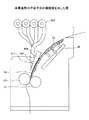
このようにして用紙7は、用紙搬送トラクタ8、転写器10、用紙搬送トラクタ9およびバッファプレート24を経て定着装置12に搬送される。定着装置12に到達した用紙7は、内部に複数のヒータを有する加熱板13で加熱された後、内部に複数本のヒータランプ25を備えた加熱ローラ14と加圧ローラ15からなる一対の定着ローラによって形成されるニップ部(加熱ローラ14と加圧ローラ15とで圧接されている部分)によって加熱加圧されながら挟持搬送され、トナー像が用紙7に溶融定着される。
In this way, the
加熱ローラ14と加圧ローラ15によって送り出されてきた用紙7は、用紙送出しローラ16によってスタッカテーブル19側へ送り出されるとともに、スイングフィン17の揺動動作によってミシン目に沿って交互に折り分けられる。さらに、回転するパドル18で折りたたみ状態が整えられながら、スタッカテーブル19上に積み重ねられて行く。感光ドラム21の転写位置を通過した領域は、清掃装置20で清掃され、次の印刷動作に備えられる。
The
バッファプレート24は、用紙搬送トラクタ9および定着ローラ(加熱ローラ14,加圧ローラ15)間で用紙搬送速度差が生じた場合に、用紙7に発生する弛み、あるいは張りを吸収するためのものである。表示部318は印刷動作中の画像形成装置1の状態に基づく情報を表示する。26は加熱ローラ14表面に接触可能に、且つ巻き取り可能に設けられたウェブ部材で、加熱ローラ14表面への離型剤や潤滑油の塗布を行うためのものである。
The
このように、本実施例の定着装置12は、加熱板13や、加熱ローラ14、加圧ローラ15などを含むものである。
[加熱板13の構成]
次に、加熱板13の構成について説明する。図3に加熱板13および、加熱板13が取り付けられている加熱板フレーム30の斜視図を示す。加熱板13は、例えばアルミニウム等の金属板132と、複数本(図3の例では6本)のヒータ134から構成されている。この例では、ヒータ134は円柱状であり、該ヒータ134は、金属板132上で搬送される用紙7の幅方向に、該金属板132を貫通している。
Thus, the fixing
[Configuration of Heating Plate 13]
Next, the configuration of the
また、加熱板13は上段部136と下段部138に分割されている。そして、制御部206は、上段部136と下段部138それぞれの表面の温度設定を個別にできる。
The
加熱板13は、保持部材140によって加熱板フレーム30に固定されている。図3の例では、加熱板フレーム30は断面コ字状である。また、加熱板フレーム30は、保持部材302により定着装置12のフレーム50に固定されている。
The
また、以下の説明では、用紙7が加熱板13上を通過する際に、加熱板13のうち、用紙7が対向する面を加熱面13aとする(図4参照)。つまり、加熱板13は、用紙7のうち、加熱面13a上に存在する部分(加熱板13aと対向している部分)を加熱する。以下の説明では、用紙7のうち、加熱面13aと対向している部分を「対向部分7a」という。対向部分7aについては、後述する図5中で太線で示す。
[冷却手段]
本実施例の定着装置12では、印刷停止などの理由で、用紙7が停止した場合には、停止した用紙7の、対向部分7aを冷却手段で冷却する。冷却手段は様々あるが、例えば、冷却手段が冷却空気を生成して、該生成された冷却空気を、停止した用紙7の対向部分7aに対して、上方から冷却空気を当てて、冷却するようにしてもよい。
In the following description, the surface of the
[Cooling means]
In the fixing
また、他の冷却手段としては、定着装置12が備えられている画像形成装置の外の空気である外気(約20℃〜28℃)を取り込んで、該外気を冷却空気として停止した用紙7に当てて冷却するようにしてもよい。その理由として、通常、画像形成装置が設置される室内の温度は、定着装置12の加熱板13付近の温度よりも相対的に低い為である。そのため、本発明の冷却手段は、用紙7を冷却する際、加熱板13付近の温度よりも低温の空気であれば良いが、特に外気が好適である。以下の説明では、外気を取り込んで、停止した用紙7の対向部分7aに当てる実施形態について説明する。
Further, as another cooling means, the outside air (about 20 ° C. to 28 ° C.) that is the outside air of the image forming apparatus provided with the fixing
冷却手段100の斜視図を図4に示し、定着装置内に取り付けられた冷却手段100の側面図を図5に示す。 A perspective view of the cooling means 100 is shown in FIG. 4, and a side view of the cooling means 100 mounted in the fixing device is shown in FIG.
図4、図5に示すように、冷却手段100は、吹き付けユニット400、ダクトユニット500、吹き付けユニット400とダクトユニット500とを繋ぐ冷却空気搬送手段600とで構成されている。
As shown in FIGS. 4 and 5, the
吹き付けユニット400は、複数の取り込み手段402と、収容部材(ホルダ)404と、接続部材406とを含む。図4、図5の例では、取り込み手段402が複数(図4、図5の例では4つ)設けられている。取り込み手段402とは、例えば、ファンであり、外気を取り込み、取り込んだ空気を、吹き付け部402aから吹き付けるものである。これら4つの取り込み手段は、収容部材404に収容されている。また収容部材404の側面106aには、取り込み手段402と同数の孔106bが設けられている。そして、それぞれの孔106bには、接続部材406が取り付けられており、該接続部材406を介して冷却空気搬送手段600と、取り込み手段402とが接続されている。冷却空気搬送手段600とは、取り込み手段402から吹き付けられた外気を外気当て手段502に搬送するものであり、例えば、ホースを用いればよい。なお、外気を送風する冷却空気搬送手段600は、蛇腹状のホースとなっており、加熱板フレーム30と共に移動するダクトユニット500に追従することが可能な構成となっている。また、冷却空気搬送手段600は、取り込み手段402と同数設けられる。
The
ダクトユニット500は、外気当て手段502、仕切り板504、ホルダ506などを含む。また、外気当て手段502は、冷却空気搬送手段600と、口金508により接続される。外気当て手段502の中は、空洞であり、また、形状は三角柱状であり、例えば、ダクトである。外気当て手段502は、取り込み手段402から吹き付けられた外気を対向部分7aに当てるための外気放出口502aを有する。
The
外気当て手段502は、取り込み手段402から吹き付けられた外気を、冷却空気として、外気放出口502aから、停止した用紙7の対向部分7aに当てることで冷却する。また、冷却空気搬送手段600、口金508、外気当て手段502は、取り込み手段402と同数(この例では4つ)である。
The outside
また、外気当て手段502はホルダ506に固定されている。そして、ホルダ506は、フレーム30に固定されている。また、加熱板13は保持部材140によりフレーム30に固定されている。ダクトユニット500は、加熱板13付近に配置される。また、外気当て手段502の外気が放出される外気放出口502aと、加熱板13の加熱面13aとの間には、所定の間隔(用紙7が搬送可能な間隔)が形成されて、ダクトユニット500は配置される。
Further, the outside air contact means 502 is fixed to the
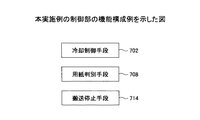
また、制御部206の機能構成例を図8に示す。用紙7の搬送の停止は、制御部206内の搬送停止手段714が行う。用紙7の搬送停止時、または、該搬送停止時から所定時間経過後に、制御部206内の冷却制御手段702がエンジン部319を介して、冷却手段100を起動させ、加熱板13上に停止した用紙7に対して冷却を行う。また、上述のように、この第1実施形態の定着装置では、用紙7の搬送が停止すると、該停止した用紙7の、対向部分7aを冷却手段により冷却する。そうすることで、加熱板13からの加熱による、用紙7の対向部分7aの損傷を防ぐことが出来る。特に、用紙7が、糊付圧着紙である場合には、加熱板13からの加熱により、糊付圧着紙に含まれる水分が蒸発し、糊の粘着性が低下するという問題があった。そこで、本実施例の冷却装置により、用紙7の対向部分7a(糊付圧着紙)を冷却することで、粘着性の低下を防ぐことが出来る。なお、糊付圧着紙とは、予め糊が含まれている用紙であり、例えば、圧着はがきのようなものが挙げられる。
An example of the functional configuration of the
また、本実施形態の定着装置では、用紙の対向部分7aに対して上方から、冷却空気を当てる。従って、用紙全体を均等に冷却できることから、冷却効率も頗る良くなる。
In the fixing device of the present embodiment, cooling air is applied from above to the facing
<第2実施形態>
第2実施形態として、取り込み手段402は複数あり(図4の例では、4つ)この4つの取り込み手段402は、搬送される用紙7の幅方向に沿って配列させることが好ましい。そして、用紙7の幅に応じた数の取り込み手段402と外気当て手段502を用いて、搬送停止した用紙7に外気を当てる。
Second Embodiment
As the second embodiment, there are a plurality of taking-in means 402 (four in the example of FIG. 4). It is preferable that the four taking-in
ここで、「用紙7の幅に応じた数の取り込み手段402」について説明すると、外気放出口402aの用紙幅方向の合計長さと、用紙7の幅とが、最も近くなるように、用いる取り込み手段402の数を選択して、該選択された数の取り込み手段406を用いることである。また、用いられる取り込み手段402の数の選択は、制御部206により行われる。また、用紙の幅6はユーザが測定して、入力部317から入力して、制御部206に送信しても良い。また、図示しない用紙幅センサが、用紙の幅を検出し、該検出された用紙の幅を制御部206に送信しても良い。
Here, the “number of capturing means 402 corresponding to the width of the
このように、用紙7の幅に応じた数の取り込み手段402を用いる理由は、用紙の幅が狭い場合に、用紙が無い部分の加熱板13に直接冷却風があたることにより、加熱板13の温度を下げる作用を与える一方で加熱板13自体は設定温度に保とうとする制御が働く。このため、相反する動きをすることで無駄な電力を消費することになる。従って、用紙の幅に合わせて動作させる取り込み手段402の数を変更することで、消費電力の低減を図ることが出来る。
As described above, the reason why the number of capturing means 402 corresponding to the width of the
<第3実施形態>
第3実施形態として、隣接する前記複数の外気当て手段の間に仕切り板が配置させることが好ましい。例えば、図4に示すように、隣接する外気当て手段502の間に、仕切り板504が設けられる。該仕切り板は、複数の外気当て手段502それぞれを仕切るためのものである。該仕切り板を設けることで、隣の外気当て手段502からの外気が回り込むことを防止できる。
<Third Embodiment>
As a third embodiment, it is preferable that a partition plate is disposed between the plurality of adjacent outside air contact means. For example, as shown in FIG. 4, a
<第4実施形態>
第4実施形態として冷却空気搬送手段600であるホースを伸縮自在とすることが好ましい。具体的には、例えば蛇腹状とする、ホース長に余裕を持たせるなどが考えられる。これは、加熱板フレーム30の移動に合わせ、ダクトユニット500も移動するが、この際の吹き付けユニット400とダクトユニット500との距離変化を吸収できるからである。
<Fourth embodiment>
In the fourth embodiment, it is preferable that the hose that is the cooling air conveying means 600 is extendable. Specifically, for example, a bellows shape or a hose length having a margin can be considered. This is because the
<第5実施形態>
第5実施形態として、印刷停止後に、制御部206が、画像形成部320による印刷(画像形成)開始(印刷再開)を行う。そうすると、制御部206は、印刷開始時に、冷却手段による冷却を中止する。印刷開始後に用紙7を冷却し続けると加熱ローラ14と加圧ローラ15でニップし、トナー像が融解定着されるまでの温度に達せず定着不良の原因になる。このため、印刷開始時に冷却手段100による冷却を中止することで、用紙7は、過度に冷却されることなく、加熱板13上を安定して搬送される。
<Fifth Embodiment>
As the fifth embodiment, after the printing is stopped, the
<第6実施形態>
第6実施形態では、冷却手段100による好適な冷却手法について説明する。また、以下で説明する[第1の好適な冷却手法]、[第2の好適な冷却手法]、[第3の好適な冷却手法]において、用紙7として糊付圧着紙を使用した例を示す。また、[第1の好適な冷却手法]、[第2の好適な冷却手法]では、冷却手段100の冷却空気が放出される放出口と、用紙7の対向部分7aとの距離Lは10mm〜30mmであるとする。ここで、「放出口」とは、冷却空気が放出される箇所である。冷却手段100が、図4に示すものである場合には、外気放出口502aが放出口となる。
<Sixth Embodiment>
In the sixth embodiment, a suitable cooling method by the cooling means 100 will be described. In addition, an example is shown in which a glued pressure-sensitive adhesive paper is used as the
[第1の好適な冷却手法]
第1の好適な冷却手法として、外気当て手段502(図4参照)からの外気(冷却空気)の風速が略10m/sまたは10m/sで、用紙7に吹き付けることが好ましいことが実験的に判明した。また、この場合の加熱手段の加熱温度は略95度または95度である。「加熱手段の加熱温度」とは、加熱板13の温度をいう。加熱板13の下段部138(図3参照)上の用紙7上のトナーは、上段部136を通過しており、上段部136からの加熱を受けていることから、仮固着されている。従って、外気の風速が略10m/sまたは10m/sであれば、トナーの飛散や位置ずれなどは発生せず、印刷品質には影響しない。
[First preferred cooling method]
As a first preferable cooling method, it is experimentally preferable that the wind speed of the outside air (cooling air) from the outside air applying means 502 (see FIG. 4) is approximately 10 m / s or 10 m / s and is preferably sprayed on the
[第2の好適な冷却手法]
次に、第2の好適な冷却手法について説明する。第2の好適な冷却手法では、対向部分7aは、加熱される面状のものであることから、「被加熱面7a」という。図11に示すように、冷却空気の風速が略10m/sまたは10m/sである場合には、冷却空気の進行方向αと、前記被加熱面とがなす角度θが60度以上120度以下であることが好ましいことが実験的に判明した。また、この場合の加熱手段(加熱板13)の加熱温度は略95度または95度である。この構成により、第1の好適な冷却手法と比較して、更にトナーの飛散や位置ずれなどは発生させず、かつ、被加熱面7a全体を効率よく冷却することができる。
[Second preferred cooling method]
Next, a second preferred cooling method will be described. In the second preferred cooling method, the facing
図11を用いて、角度θについて説明する。被加熱面7aは図11Aに示すように、平面状である場合と、図11Bに示すように曲面状である場合がある。まず、被加熱面7aが図11Aに示すように平面状である場合について説明する。角度θは、被加熱面7aと冷却空気の進行方向α(破線で示す)とがなす角度である。次に、被加熱面7aが図11Bに示すように曲面状である場合について説明する。この場合の角度θは、被加熱面7aの接線B(一転鎖線で示す)と、冷却空気の進行方向αがなす角度である。そして、該角度θが60度以上120度以下になるように、冷却手段100は被加熱面7aに冷却空気を当てる。
The angle θ will be described with reference to FIG. The
この第2の好適な冷却手法により、第1の好適な冷却手法と比較して、更にトナーの飛散や位置ずれなどは発生させず、かつ、被加熱面7a全体を効率よく冷却することができる。 Compared with the first preferred cooling method, the second preferred cooling method can further efficiently cool the entire surface to be heated 7a without causing toner scattering or displacement. .
[第3の好適な冷却手法]
次に、第3の好適な冷却手法について説明する。冷却空気の進行方向は、被加熱面7aに対して、垂直または略垂直であることが好ましいことが実験的に判明した。図7に第3の好適な冷却手法について示す。図7Aのように、被加熱面7aが平面状である場合には、冷却空気の進行方向αが被加熱面7aと略垂直または垂直になるように、冷却手段は冷却空気を被加熱面7aに当てる。また、図7Bのように、被加熱面7aが曲面状である場合には、冷却空気の進行方向αが被加熱面7aの接線Bと略垂直かまたは垂直になるように、冷却手段は冷却空気を対向部分7aに当てる。
[Third preferred cooling method]
Next, a third preferred cooling method will be described. It has been experimentally found that the traveling direction of the cooling air is preferably perpendicular or substantially perpendicular to the
第3の好適な冷却手法であれば、第1、第2の好適な冷却手法と比較して、更にトナーの飛散や位置ずれなどは発生させず、かつ、被加熱面7a全体を効率よく冷却することができる。また、第3の好適な冷却手法であれば、冷却空気の風速が10m/sより速くても、トナーの飛散や位置ずれが生じることはない。
<第7実施形態>
次に、第7実施形態を説明する。搬送手段による搬送が停止して、冷却手段100による冷却後の用紙7の対向部分7aの含水率を含水率X1とする。また、該対向部分7aが停止される直前の含水率を含水率X2とする。第7実施形態の冷却手段100は、含水率X1が、含水率X2と同一または略同一となるように、対向部分7aを冷却する。つまり、第7実施形態の冷却手段100は、対向部分7aの含水率X1が、停止される直前の対向部分7aの含水率X2と同一または略同一となるように、対向部分7aを冷却する。
With the third preferred cooling method, compared to the first and second preferred cooling methods, there is no further toner scattering or positional deviation, and the entire
<Seventh embodiment>
Next, a seventh embodiment will be described. The conveyance by the conveyance unit is stopped, and the moisture content of the facing
一般的に、加熱板13の加熱や、冷却手段100による冷却により、含水率X1と含水率X2とが異なると、特性が失われる用紙がある。例えば、含水率X1と含水率X2とが異なると、後述する糊付圧着紙の場合には、糊付圧着紙の特性である粘着力が失われる場合がある。このように、含水率X1と含水率X2とが異なると、特性が失われる用紙を特性用紙Sという。以下に、含水率X1と含水率X2とが同一または略同一になるような冷却手法の一例について説明する。
Generally, there is a sheet whose characteristics are lost when the moisture content X1 and the moisture content X2 are different due to heating of the
例えば、印刷に用いる特性用紙Sが1種類であることが明らかな場合には、該特性用紙S1の含水率X1と含水率X2とが同一また略同一になるように、予め、冷却手段100の冷却パラメータを定めておき、主記憶部312、補助記憶部313、記憶媒体515の何れか(以下では、「主記憶部312など」や「記憶手段」という。)に予め記憶させておく。
For example, when it is clear that there is one type of characteristic paper S used for printing, the cooling means 100 is previously set so that the moisture content X1 and the moisture content X2 of the characteristic paper S1 are the same or substantially the same. Cooling parameters are determined and stored in advance in any of the
ここで、冷却パラメータとは、冷却手段100による冷却について示すパラメータであり、例えば、冷却空気の温度(冷却温度)、冷却空気の風速のうち、少なくとも1つである。そして、予め記憶された冷却パラメータに基づいて、冷却手段100は、対向部分7aを冷却する。冷却手段100の冷却制御は、制御部206中の冷却制御手段702(図8参照)が行う。冷却制御手段702が主記憶部312などに記憶されている制御パラメータに基づいて、冷却手段100に冷却させる。
Here, the cooling parameter is a parameter indicating cooling by the
また、図9に示すように、冷却手段100は、風速切替手段102、温度切替手段104のうち少なくとも1つを有することが好ましい。風速切替手段102とは、冷却手段100の冷却空気の風速を複数段階に切り替えることができるものである。また、温度切替手段104とは、冷却手段100の冷却空気の温度を複数段階に切り替えることができるものである。
As shown in FIG. 9, the
冷却制御手段702が、冷却手段100の冷却空気の風速を切り替える場合には、風速切替手段102により風速を切り替えればよい。風速切替手段102は、例えば、取り込み手段402で取り込まれた外気を吹き付け部402aに吹き付ける際の速度を変更するものであり、取り込み手段402内に設けられるものである。
When the
また、冷却制御手段702が、冷却手段100の冷却空気の温度を切り替える場合には、温度切替手段104により、冷却空気の温度を切り替えることができる。
In addition, when the
このように、印刷用紙が、含水率X1と含水率X2とが異なると、特性が失われるような特性用紙Sの場合には、予め含水率X1と含水率X2とが同一、または略同一になるような、冷却パラメータを求めておき、記憶させておく。そして、該冷却パラメータに基づいて、冷却制御手段702は、冷却手段100に冷却させる。従って、加熱板13による加熱後および冷却手段100の冷却後においても、含水率X1と含水率X2とを同一、または略同一にすることができ、特性用紙Sの特性を損なうことはないという効果を奏する。
As described above, when the printing paper is a characteristic paper S in which the characteristics are lost when the moisture content X1 and the moisture content X2 are different, the moisture content X1 and the moisture content X2 are the same or substantially the same in advance. Such cooling parameters are obtained and stored. Then, based on the cooling parameter, the cooling control means 702 causes the cooling means 100 to cool. Therefore, even after heating by the
<第8実施形態>
次に、第8実施形態について説明する。第7実施形態では、特性用紙Sが1種類の場合について説明した。実施形態8では、特性用紙Sが複数種類用いられる場合について説明する。特性用紙Sが複数ある場合には、それぞれの特性用紙Sごとに、特性用紙Sの特性が失われない含水率(以下、「適切含水率」という。)になるための冷却パラメータを測定する。そして、それぞれの特性用紙Sと該測定された冷却パラメータとを対応付ける対応情報を予め主記憶部312などに記憶させておく。図10に対応情報の一例を示す。ここで、冷却パラメータは、冷却温度C、風速V、としているが、これらのうちの少なくとも1つでよい。
<Eighth Embodiment>
Next, an eighth embodiment will be described. In the seventh embodiment, the case where there is one type of characteristic paper S has been described. In the eighth embodiment, a case where a plurality of types of characteristic paper S is used will be described. When there are a plurality of characteristic sheets S, a cooling parameter is measured for each characteristic sheet S so as to obtain a moisture content (hereinafter referred to as “appropriate moisture content”) at which the characteristics of the characteristic sheet S are not lost. Correspondence information that associates each characteristic sheet S with the measured cooling parameter is stored in advance in the
図10の例では、例えば、特性用紙の種類がS1である場合には、適切含水率W1であり、冷却温度はC1であり、風速はV1であり、である。冷却制御手段702は、冷却温度がC1となり、風速がV1となるように、冷却手段100を制御する。 In the example of FIG. 10, for example, when the type of characteristic paper is S 1 , the water content is appropriate W 1 , the cooling temperature is C 1 , and the wind speed is V 1 . The cooling control means 702 controls the cooling means 100 so that the cooling temperature becomes C 1 and the wind speed becomes V 1 .
そして、制御部206中の用紙判別手段708が、印刷される用紙の種類を判別する。用紙の判別の手法は様々あるが、例えば、ユーザが、入力部317または表示部318(図1参照)から用紙の種類を入力するようにしてもよい。例えば、用紙の種類が、糊付圧着紙である場合には、ユーザは、糊付圧着紙である旨の情報を入力部317に入力する。例えば、表示部318に用紙の種類を選択させるソフトキーを、電子的に表示し、ユーザが該ソフトキーを押下することで、用紙の種類を入力することができる。そして、入力部317または表示部318から入力された用紙の種類を、用紙判別手段708が取得する。
Then, a
また、例えば、用紙ホッパ11(図2参照)に用紙判別センサを設け、該用紙判別センサが、用紙の種類を判別し、該用紙判別センサからのセンサ出力を用いて、用紙判別手段708が用紙の種類を取得するようにしても良い。例えば、予め用紙に、用紙を識別するための用紙識別パターンを付加する。そして、用紙判別センサが、付加された用紙識別パターンを識別し、センサ出力するようにしてもよい。 Further, for example, a paper discrimination sensor is provided in the paper hopper 11 (see FIG. 2), the paper discrimination sensor discriminates the type of the paper, and the paper discrimination means 708 uses the sensor output from the paper discrimination sensor. You may make it acquire the kind of. For example, a paper identification pattern for identifying the paper is added to the paper in advance. The paper discrimination sensor may identify the added paper identification pattern and output the sensor.
この第8実施形態によれば、特性用紙Sが複数種類用いられる場合にも、含水率X1と含水率X2とを略同一、または、同一にすることができる。従って、加熱板13による加熱後および冷却手段100の冷却後においても、特性用紙Sの特性を損なうことはないという効果を奏する。
According to the eighth embodiment, even when a plurality of types of characteristic paper S are used, the moisture content X1 and the moisture content X2 can be made substantially the same or the same. Therefore, even after heating by the
また、第7実施形態や第8実施形態では、含水率X1と含水率X2とが同一または略同一になるように、対向部分7aを冷却したが、冷却パラメータに基づいて、適切含水率になるように、対向部分7aを冷却してもよい。
Moreover, in 7th Embodiment or 8th Embodiment, although the opposing
<第9実施形態>
次に、第9実施形態を説明する。第9実施形態の定着装置を備える画像形成装置は用紙(記録媒体)の表面温度を検知する検知手段610を有する。図5に示すように、検知手段610は例えば、外気当て手段502の内部に設けられる。また、検知手段610として、例えば、赤外線温度センサを用いればよい。
<Ninth Embodiment>
Next, a ninth embodiment will be described. The image forming apparatus including the fixing device according to the ninth embodiment includes a detecting
また、予め、用紙表面の適切な温度範囲Dを定めておく。この温度範囲Dとは、例えば、室温±5度とすればよい。そして、冷却制御手段702は、用紙表面の温度がこの温度範囲Dに属するように、冷却手段100を制御する。また温度範囲Dは、予め記憶手段に記憶させておく。
In addition, an appropriate temperature range D on the paper surface is determined in advance. The temperature range D may be, for example, room temperature ± 5 degrees. The cooling
用紙表面の温度が、この温度範囲Dに属している場合には、冷却手段100は用紙7を冷却する必要がないので、冷却制御手段702は、冷却手段100による冷却を中止させる。また、用紙表面の温度が、温度範囲Dを逸脱しそうな場合、また、温度範囲Dを逸脱した場合には、冷却制御手段702は、冷却手段100に用紙7を冷却させる。
When the temperature of the sheet surface belongs to this temperature range D, the
このように、第9実施形態であれば、予め、用紙表面の適切な温度範囲Dを定めておく。そして、冷却制御手段702は、用紙表面の温度が、温度範囲Dに属している場合には、冷却手段100による冷却を中止する。従って、冷却コストを削減することが出来る。また、用紙表面の温度が、温度範囲Dを逸脱しそうな場合、または温度範囲Dを逸脱した場合には、冷却制御手段702は、冷却手段100に用紙7を冷却させる。従って、適切に、過度に加熱された用紙7を冷却することが出来る。
Thus, in the ninth embodiment, an appropriate temperature range D on the paper surface is determined in advance. Then, the cooling
<第10実施形態>
第7実施形態、第8実施形態では、特性用紙Sについて説明した。第10実施形態では、特性用紙Sが糊付圧着紙の場合について説明する。以下では、特性用紙を糊付圧着紙7として説明する。ここで、糊付圧着紙7とは、耐水性の用紙表面に天然ゴム系の糊が予め含まれている用紙であり、例えば、圧着はがきのようなものが挙げられる。糊付圧着紙7が、加熱板13上で停止すると、糊付圧着紙7内の水分が蒸発することで、粘着力が低下する。そこで、度重なる実験の結果、糊付圧着紙7は、耐水性の用紙表面に天然ゴム系の糊を塗布した規格の場合に、含水率が略4%または4%であるときに、圧着強度が適切になることが判明した。一般的に、糊付圧着紙7表面の空気の温度により飽和水蒸気量は変化する。そこで、冷却手段100により、糊付圧着紙7表面の空気の温度を冷却し、糊付圧着紙7表面の飽和水蒸気量を減少させる。糊付圧着紙7表面の飽和水蒸気量が減少されると、糊付圧着紙7から蒸発される水分量も減少する。
<Tenth Embodiment>
In the seventh embodiment and the eighth embodiment, the characteristic sheet S has been described. In the tenth embodiment, a case where the characteristic paper S is a pressure-sensitive adhesive paper with glue will be described. Hereinafter, the characteristic paper will be described as the glued pressure-
そして、冷却手段100は、含水率X1と含水率X2と同一または略同一となるように、対向部分7aを冷却する。該冷却手法は、第7実施形態、第8実施形態で説明した冷却パラメータを用いて行えばよい。これにより、糊付圧着紙7の圧着強度を適切にすることができる。
And the cooling means 100 cools the opposing
そして、含水率が略4%になる画像形成装置内の温度・湿度を確認するために実験を行った。該実験により、冷却パラメータを求めることができる。図6に、耐水性の用紙表面に天然ゴム系の糊を塗布した規格の糊付圧着紙についての、画像形成装置内の環境温湿度と含水率の関係を示す。また、図6は、加熱板の加熱温度が90度の場合を示したものである。 An experiment was conducted in order to confirm the temperature and humidity in the image forming apparatus at which the moisture content was approximately 4%. By this experiment, the cooling parameter can be obtained. FIG. 6 shows the relationship between the environmental temperature and humidity in the image forming apparatus and the moisture content of the standard glue-bonded pressure-sensitive paper in which natural rubber glue is applied to the surface of water-resistant paper. FIG. 6 shows a case where the heating temperature of the heating plate is 90 degrees.
図6では、縦軸が糊付圧着紙の含水率を示し、横軸が冷却時間を示す。冷却時間は、冷却手段が冷却開始時から測定された時間である。また、例えば、破線で四角を付した線については、画像形成装置内の温度が45℃であり、湿度が30%であることを示す。以下では、線の示し方について例えば、実線で四角を付した線を線(四角、実線)と示す。 In FIG. 6, the vertical axis represents the moisture content of the pressure-bonded pressure-sensitive adhesive paper, and the horizontal axis represents the cooling time. The cooling time is a time measured from when the cooling means starts cooling. Further, for example, a broken line with a square indicates that the temperature in the image forming apparatus is 45 ° C. and the humidity is 30%. Hereinafter, for example, a line indicated by a solid line with a square is indicated as a line (square, solid line).
例えば、放置時間が1分の時は、線(四角、破線)である温度45℃、湿度30%の場合に含水率が4%に近づく。そして、放置時間が10分の時は、線(三角、実線)である温度60℃、湿度30%の場合、または、線(三角、破線)である温度60℃、湿度40%の場合に、含水率が4%に近づく。 For example, when the standing time is 1 minute, the moisture content approaches 4% when the temperature is 45 ° C. and the humidity is 30% as a line (square, broken line). When the standing time is 10 minutes, when the temperature is 60 ° C. and the humidity is 30% as a line (triangle, solid line), or when the temperature is 60 ° C. and the humidity is 40% as a line (triangle, broken line), The water content approaches 4%.
さらに詳しくは、糊付圧着紙7の環境温度が高ければ高いほど飽和水蒸気量も高くなるため、用紙7から蒸発される水分は多くなる。これは図6に示す80℃から45℃の実験で温度による含水率の低下からも証明された。また、空気中の水分量(湿度60%)が高くても、温度が高い80℃環境下では、急激に水分が蒸発し、その後、実験結果では10分程度かけてゆっくり、糊付圧着紙7に水分が戻ってくることが分かった。これは、停止した用紙に仮に水分を加えても、用紙に浸透するには時間を要するということなので、再印刷の業務の妨げとなる。
More specifically, the higher the environmental temperature of the glue-bonded pressure-
従って、この実験結果では、用紙温度を下げることで、含水率の低下量を抑えることが可能で、且つ効率が良いことが分かった。また、用紙から奪われた水分は湿度が高いだけでは用紙の含水率を4%に保つことは困難であることから、冷却により含水率を保つようにする。 Therefore, it was found from this experimental result that the amount of decrease in the moisture content can be suppressed and the efficiency is improved by lowering the paper temperature. Further, since the moisture deprived from the paper is difficult to keep the moisture content of the paper at 4% only by high humidity, the moisture content is kept by cooling.
また、図6に示す実験のように、糊付圧着紙7の種類ごとに適切含水率、画像形成装置内の温度、湿度、放置時間を予め測定することで、第7実施形態、第8実施形態で説明した冷却パラメータ(冷却温度、風速、のうち少なくとも1つ)や対応情報(図10参照)を求めることができる。そして、該対応情報に基づいて、冷却手段100の冷却パラメータに基づいて糊付圧着紙7を冷却すると、糊付圧着紙7の粘着力の低下をさらに防ぐことが可能である。
Further, as in the experiment shown in FIG. 6, the seventh embodiment and the eighth embodiment are performed by measuring in advance the appropriate moisture content, the temperature, the humidity, and the leaving time in the image forming apparatus for each type of the adhesive-bonded
1・・・レーザビームプリンタ、2・・・コロナ帯電器、3・・・回転多面鏡、4・・・光源、5・・・fθレンズ、6・・・現像装置、7・・・用紙、8・・・用紙搬送トラクタ、9・・・用紙搬送トラクタ、10・・・転写器、12・・・定着装置、13・・・加熱板(加熱手段)、14・・・加熱ローラ、15・・・加圧ローラ、16・・・用紙送出しローラ、17・・・スイングフィン、18・・・パドル、19・・・スタッカテーブル、21・・・感光ドラム、22・・・コントローラ、23・・・表示画面、24・・・バッファプレート、26・・・ウェブ部材。
DESCRIPTION OF
Claims (15)
前記記録媒体の前記搬送を停止させる搬送停止手段と、
加熱面を有し、前記記録媒体の該加熱面上の部分を加熱する加熱手段と、
該加熱手段で加熱された前記記録媒体を定着する定着手段と、
前記搬送が停止した前記記録媒体の前記加熱面上の上方から冷却空気を当てることで該部分を冷却する冷却手段と、
を有し、
前記冷却手段は、
外気を取り込み、該外気を吹き付ける取り込み手段と、
前記吹き付けられた前記外気を前記冷却空気として、前記部分に当てることで前記冷却する外気当て手段と、を有し、
前記取り込み手段は、前記記録媒体の幅方向に沿って、複数配列されており、
前記記録媒体の幅に応じた数の前記取り込み手段と前記外気当て手段を用いて、前記部分に前記冷却空気を当てることを特徴とする定着装置。 Conveying means for conveying the recording medium;
Transport stop means for stopping the transport of the recording medium;
A heating means having a heating surface and heating a portion of the recording medium on the heating surface;
Fixing means for fixing the recording medium heated by the heating means;
Cooling means for cooling the portion by applying cooling air from above the heating surface of the recording medium on which the conveyance has stopped;
I have a,
The cooling means is
An intake means for taking in outside air and blowing the outside air;
The outside air spraying means for cooling the sprayed outside air as the cooling air by hitting the portion,
A plurality of the capturing means are arranged along the width direction of the recording medium,
The fixing device is characterized in that the cooling air is applied to the portion by using a number of the intake means and the outside air application means corresponding to the width of the recording medium .
前記記録媒体の前記搬送を停止させる搬送停止手段と、
加熱面を有し、前記記録媒体の該加熱面上の部分を加熱する加熱板と、
前記搬送が停止した前記記録媒体の前記加熱面上の部分の上方から冷却空気を当てることで該部分を冷却する冷却手段とを有し、
前記冷却手段は、
外気を取り込み、該外気を吹き付ける取り込み手段と、
前記外気を前記冷却空気として、前記部分に当てることで前記冷却する外気当て手段と、を有し、
前記取り込み手段は、前記記録媒体の幅方向に沿って、複数配列されており、
前記記録媒体の幅に応じた数の前記取り込み手段と前記外気当て手段を用いて、前記部分に前記冷却空気を当てる定着装置。 Conveying means for conveying the recording medium;
Transport stop means for stopping the transport of the recording medium;
A heating surface, a heating plate for heating the portion on the heating surface of the recording medium,
Have a cooling means for cooling the partial by directing cooling air from the upper portion on the heating surface of the recording medium to the conveying is stopped,
The cooling means is
An intake means for taking in outside air and blowing the outside air;
The outside air application means for cooling by applying the outside air as the cooling air to the portion;
A plurality of the capturing means are arranged along the width direction of the recording medium,
A fixing device that applies the cooling air to the portion using the number of the intake units and the external air application unit corresponding to the width of the recording medium .
隣接する前記外気当て手段の間に、該外気当て手段それぞれを仕切るための仕切り板が配置されていることを特徴とする請求項1又は2記載の定着装置。 A plurality of the outside air application means are arranged,
Between Kigai air blowing members prior adjacent fixing device according to claim 1 or 2, wherein the partition plate is disposed for partitioning the respective external air blowing members.
前記冷却手段は、前記加熱面上で搬送が停止された記録媒体の種類と、対応する前記冷却パラメータに基づいて、該記録媒体の前記部分を冷却することを特徴とする請求項1ないし6何れか1項に記載の定着装置。 A storage unit in which correspondence information in which a type of the recording medium is associated with a cooling parameter for achieving a moisture content at which the characteristics of the recording medium are not lost is stored;
It said cooling means, the type of the recording medium carried on the heating surface is stopped, based on the corresponding said cooling parameters, any claims 1, characterized in that cooling the portion of the recording medium 6 The fixing device according to claim 1.
前記冷却手段の前記冷却空気が放出される放出口と前記被加熱面までの距離が10mm〜30mmであり、前記冷却空気の風速が10m/sである場合に、前記冷却空気の進行方向と、前記被加熱面とがなす角度が60度以上120度以下であることを特徴とする請求項1ないし10何れか1項に記載の定着装置。 The part is a heated surface,
When the distance from the discharge port of the cooling means to which the cooling air is discharged and the heated surface is 10 mm to 30 mm, and the wind speed of the cooling air is 10 m / s, the traveling direction of the cooling air the fixing device according to claims 1 to any one 10 the angle between the heated plane is equal to or less than 120 degrees 60 degrees.
前記冷却空気の進行方向は、前記被加熱面に対して、垂直であることを特徴とする請求項1ないし11何れか1項に記載の定着装置。 The part is a heated surface,
The traveling direction of the cooling air, the relative heated surface, fixing device according to 11 any one claims 1, characterized in that a vertical.
前記記録媒体に画像形成する画像形成手段を、を有することを特徴とする画像形成装置。 A fixing device according to any one of claims 1 to 12 ,
An image forming apparatus comprising image forming means for forming an image on the recording medium.
前記表面温度が規定の温度範囲に属するように、前記冷却手段を制御する冷却制御手段と、を有することを特徴とする13又は14記載の画像形成装置。 Detecting means for detecting the surface temperature of the recording medium;
15. The image forming apparatus according to claim 13 , further comprising a cooling control unit that controls the cooling unit so that the surface temperature belongs to a specified temperature range.
Priority Applications (5)
| Application Number | Priority Date | Filing Date | Title |
|---|---|---|---|
| JP2010215704A JP5581939B2 (en) | 2010-03-15 | 2010-09-27 | Fixing device, image forming apparatus |
| US13/064,103 US8787817B2 (en) | 2010-03-15 | 2011-03-07 | Fixing device and image forming apparatus |
| EP11157726.8A EP2369428A3 (en) | 2010-03-15 | 2011-03-10 | Fixing device and image forming apparatus |
| CN201110065547.6A CN102193458B (en) | 2010-03-15 | 2011-03-11 | Fixing device and imaging device |
| CN201510131841.0A CN104698797B (en) | 2010-03-15 | 2011-03-11 | Fixing device and imaging device |
Applications Claiming Priority (3)
| Application Number | Priority Date | Filing Date | Title |
|---|---|---|---|
| JP2010058414 | 2010-03-15 | ||
| JP2010058414 | 2010-03-15 | ||
| JP2010215704A JP5581939B2 (en) | 2010-03-15 | 2010-09-27 | Fixing device, image forming apparatus |
Publications (2)
| Publication Number | Publication Date |
|---|---|
| JP2011215581A JP2011215581A (en) | 2011-10-27 |
| JP5581939B2 true JP5581939B2 (en) | 2014-09-03 |
Family
ID=44123450
Family Applications (1)
| Application Number | Title | Priority Date | Filing Date |
|---|---|---|---|
| JP2010215704A Expired - Fee Related JP5581939B2 (en) | 2010-03-15 | 2010-09-27 | Fixing device, image forming apparatus |
Country Status (4)
| Country | Link |
|---|---|
| US (1) | US8787817B2 (en) |
| EP (1) | EP2369428A3 (en) |
| JP (1) | JP5581939B2 (en) |
| CN (2) | CN102193458B (en) |
Families Citing this family (6)
| Publication number | Priority date | Publication date | Assignee | Title |
|---|---|---|---|---|
| JP2014137487A (en) | 2013-01-17 | 2014-07-28 | Ricoh Co Ltd | Fixing device |
| JP2016006472A (en) | 2014-03-12 | 2016-01-14 | 株式会社リコー | Fixing device and image forming apparatus |
| JP2016184012A (en) * | 2015-03-25 | 2016-10-20 | 富士ゼロックス株式会社 | Image forming apparatus |
| JP2017111162A (en) | 2015-12-14 | 2017-06-22 | 株式会社リコー | Fixing device and image forming apparatus |
| JP2017198936A (en) * | 2016-04-28 | 2017-11-02 | コニカミノルタ株式会社 | Image formation system and cooling control method |
| JP2022133782A (en) * | 2021-03-02 | 2022-09-14 | 株式会社リコー | Conveying device, liquid ejection device, image forming device, and post-processing device |
Family Cites Families (20)
| Publication number | Priority date | Publication date | Assignee | Title |
|---|---|---|---|---|
| JPS5766461A (en) * | 1980-10-13 | 1982-04-22 | Mitsubishi Electric Corp | Fixation device |
| JPH04321062A (en) | 1991-04-22 | 1992-11-11 | Hitachi Koki Co Ltd | Both side printer for serial printing paper |
| EP0638855B1 (en) | 1993-07-28 | 1995-06-21 | Siemens Nixdorf Informationssysteme Aktiengesellschaft | Thermal fixing device for image carriers printed on one or two sides in a printer or copying machine |
| JPH08234604A (en) * | 1995-02-24 | 1996-09-13 | Hitachi Koki Co Ltd | Fixing device for electrophotographic device |
| US5787321A (en) * | 1996-02-09 | 1998-07-28 | Asahi Kogaku Kogyo Kabushiki Kaisha | Temperature controlling device for fixing unit |
| JP3659369B2 (en) | 1996-10-25 | 2005-06-15 | リコープリンティングシステムズ株式会社 | Fixing apparatus and fixing method for electrophotographic apparatus |
| JP2000238374A (en) | 1999-02-24 | 2000-09-05 | Oki Data Corp | Color imaging apparatus |
| US6374063B1 (en) * | 2000-09-28 | 2002-04-16 | Toshiba Tec Kabushiki Kaisha | Fixing device used for image forming apparatus |
| JP4032751B2 (en) | 2002-01-16 | 2008-01-16 | リコープリンティングシステムズ株式会社 | Heat fixing apparatus and image forming apparatus using the same |
| JP4332366B2 (en) * | 2003-04-07 | 2009-09-16 | キヤノン株式会社 | Image forming apparatus |
| JP4380232B2 (en) | 2003-06-13 | 2009-12-09 | リコープリンティングシステムズ株式会社 | Inkjet printer |
| JP2005099552A (en) | 2003-09-26 | 2005-04-14 | Ricoh Printing Systems Ltd | Printing device, both-side printing system and both-side printing device |
| JP4523850B2 (en) | 2005-02-04 | 2010-08-11 | 株式会社リコー | Fixing device for electrophotographic printer |
| JP2006267769A (en) | 2005-03-25 | 2006-10-05 | Fuji Xerox Co Ltd | Fixing device for continuous form |
| JP2007183353A (en) | 2006-01-05 | 2007-07-19 | Ricoh Printing Systems Ltd | Fixing device and image forming apparatus provided with the same |
| JP2007328161A (en) * | 2006-06-08 | 2007-12-20 | Canon Inc | Image heating apparatus |
| JP5035954B2 (en) * | 2006-08-18 | 2012-09-26 | 株式会社リコー | Printing system |
| JP2010058414A (en) | 2008-09-05 | 2010-03-18 | Sekisui Chem Co Ltd | Surface protective film |
| CN201368967Y (en) * | 2008-12-31 | 2009-12-23 | 特新机电(东莞)有限公司 | Fixing device |
| JP5453860B2 (en) | 2009-03-13 | 2014-03-26 | 宇部興産株式会社 | Electrolyte membrane for fuel cell |
-
2010
- 2010-09-27 JP JP2010215704A patent/JP5581939B2/en not_active Expired - Fee Related
-
2011
- 2011-03-07 US US13/064,103 patent/US8787817B2/en not_active Expired - Fee Related
- 2011-03-10 EP EP11157726.8A patent/EP2369428A3/en not_active Withdrawn
- 2011-03-11 CN CN201110065547.6A patent/CN102193458B/en not_active Expired - Fee Related
- 2011-03-11 CN CN201510131841.0A patent/CN104698797B/en not_active Expired - Fee Related
Also Published As
| Publication number | Publication date |
|---|---|
| US20110222890A1 (en) | 2011-09-15 |
| JP2011215581A (en) | 2011-10-27 |
| CN102193458B (en) | 2016-02-24 |
| CN102193458A (en) | 2011-09-21 |
| CN104698797A (en) | 2015-06-10 |
| CN104698797B (en) | 2017-06-23 |
| EP2369428A2 (en) | 2011-09-28 |
| EP2369428A3 (en) | 2016-10-05 |
| US8787817B2 (en) | 2014-07-22 |
Similar Documents
| Publication | Publication Date | Title |
|---|---|---|
| JP5581939B2 (en) | Fixing device, image forming apparatus | |
| US20110199448A1 (en) | Image forming apparatus and drying method in image forming apparatus | |
| JP4811146B2 (en) | Paper discharge device and image forming apparatus | |
| JP2006293067A (en) | Image forming apparatus | |
| JP2010078659A (en) | Fixing device, gloss providing device and image forming system | |
| US9523959B2 (en) | Image forming apparatus with control unit configured to reduce the air blown by a blower unit reaching an exposure unit | |
| JP5831074B2 (en) | Preheating plate, fixing device and printing device provided with the same | |
| JP6145425B2 (en) | Image forming apparatus | |
| JP2017049288A (en) | Image formation device, and control method of image formation device | |
| JP5402743B2 (en) | Fixing apparatus and image forming apparatus | |
| JP2010002738A (en) | Curl determination method and curl determination device for transfer paper, and image forming apparatus using the same | |
| JP2012098448A (en) | Image forming apparatus | |
| JP2016109977A (en) | Image forming apparatus | |
| JPH11139680A (en) | Paper sheet cooler for electrophotography device | |
| JP2014010194A (en) | Image forming apparatus | |
| JP2014219553A (en) | Image forming apparatus | |
| JP2005077651A (en) | Fixing device of electrophotographic apparatus | |
| JP6276660B2 (en) | Medium transport mechanism, fixing device, and image forming apparatus | |
| JP2023026226A (en) | Image forming apparatus | |
| KR100555720B1 (en) | Electrophotographic image forming apparatus and the fusing unit controlling method thereof | |
| JP2006215357A (en) | Fixing device | |
| JP2005227596A (en) | Printer | |
| JP2021041603A (en) | Recording device and heating device | |
| JP2007308270A (en) | Stacker device for continuous paper electrophotographic device | |
| JP2019168564A (en) | Image forming device |
Legal Events
| Date | Code | Title | Description |
|---|---|---|---|
| A621 | Written request for application examination |
Free format text: JAPANESE INTERMEDIATE CODE: A621 Effective date: 20130813 |
|
| A977 | Report on retrieval |
Free format text: JAPANESE INTERMEDIATE CODE: A971007 Effective date: 20140205 |
|
| A131 | Notification of reasons for refusal |
Free format text: JAPANESE INTERMEDIATE CODE: A131 Effective date: 20140218 |
|
| A521 | Written amendment |
Free format text: JAPANESE INTERMEDIATE CODE: A523 Effective date: 20140418 |
|
| TRDD | Decision of grant or rejection written | ||
| A01 | Written decision to grant a patent or to grant a registration (utility model) |
Free format text: JAPANESE INTERMEDIATE CODE: A01 Effective date: 20140617 |
|
| A61 | First payment of annual fees (during grant procedure) |
Free format text: JAPANESE INTERMEDIATE CODE: A61 Effective date: 20140630 |
|
| R151 | Written notification of patent or utility model registration |
Ref document number: 5581939 Country of ref document: JP Free format text: JAPANESE INTERMEDIATE CODE: R151 |
|
| LAPS | Cancellation because of no payment of annual fees |