JP2017111162A - Fixing device and image forming apparatus - Google Patents

Fixing device and image forming apparatus Download PDF

Info

Publication number
JP2017111162A
JP2017111162A JP2015242833A JP2015242833A JP2017111162A JP 2017111162 A JP2017111162 A JP 2017111162A JP 2015242833 A JP2015242833 A JP 2015242833A JP 2015242833 A JP2015242833 A JP 2015242833A JP 2017111162 A JP2017111162 A JP 2017111162A
Authority
JP
Japan
Prior art keywords
air
outer peripheral
peripheral surface
pressure roller
rotator
Prior art date
Legal status (The legal status is an assumption and is not a legal conclusion. Google has not performed a legal analysis and makes no representation as to the accuracy of the status listed.)
Pending
Application number
JP2015242833A
Other languages
Japanese (ja)
Inventor
菊島 祐樹
Yuki Kikushima
祐樹 菊島
Current Assignee (The listed assignees may be inaccurate. Google has not performed a legal analysis and makes no representation or warranty as to the accuracy of the list.)
Ricoh Co Ltd
Original Assignee
Ricoh Co Ltd
Priority date (The priority date is an assumption and is not a legal conclusion. Google has not performed a legal analysis and makes no representation as to the accuracy of the date listed.)
Filing date
Publication date
Application filed by Ricoh Co Ltd filed Critical Ricoh Co Ltd
Priority to JP2015242833A priority Critical patent/JP2017111162A/en
Priority to US15/369,592 priority patent/US10078303B2/en
Publication of JP2017111162A publication Critical patent/JP2017111162A/en
Pending legal-status Critical Current

Links

Images

Classifications

    • GPHYSICS
    • G03PHOTOGRAPHY; CINEMATOGRAPHY; ANALOGOUS TECHNIQUES USING WAVES OTHER THAN OPTICAL WAVES; ELECTROGRAPHY; HOLOGRAPHY
    • G03GELECTROGRAPHY; ELECTROPHOTOGRAPHY; MAGNETOGRAPHY
    • G03G21/00Arrangements not provided for by groups G03G13/00 - G03G19/00, e.g. cleaning, elimination of residual charge
    • G03G21/20Humidity or temperature control also ozone evacuation; Internal apparatus environment control
    • G03G21/206Conducting air through the machine, e.g. for cooling, filtering, removing gases like ozone
    • GPHYSICS
    • G03PHOTOGRAPHY; CINEMATOGRAPHY; ANALOGOUS TECHNIQUES USING WAVES OTHER THAN OPTICAL WAVES; ELECTROGRAPHY; HOLOGRAPHY
    • G03GELECTROGRAPHY; ELECTROPHOTOGRAPHY; MAGNETOGRAPHY
    • G03G15/00Apparatus for electrographic processes using a charge pattern
    • G03G15/20Apparatus for electrographic processes using a charge pattern for fixing, e.g. by using heat
    • G03G15/2003Apparatus for electrographic processes using a charge pattern for fixing, e.g. by using heat using heat
    • G03G15/2014Apparatus for electrographic processes using a charge pattern for fixing, e.g. by using heat using heat using contact heat
    • G03G15/2017Structural details of the fixing unit in general, e.g. cooling means, heat shielding means
    • GPHYSICS
    • G03PHOTOGRAPHY; CINEMATOGRAPHY; ANALOGOUS TECHNIQUES USING WAVES OTHER THAN OPTICAL WAVES; ELECTROGRAPHY; HOLOGRAPHY
    • G03GELECTROGRAPHY; ELECTROPHOTOGRAPHY; MAGNETOGRAPHY
    • G03G2215/00Apparatus for electrophotographic processes
    • G03G2215/20Details of the fixing device or porcess
    • G03G2215/2003Structural features of the fixing device
    • G03G2215/2016Heating belt
    • G03G2215/2025Heating belt the fixing nip having a rotating belt support member opposing a pressure member
    • G03G2215/2032Heating belt the fixing nip having a rotating belt support member opposing a pressure member the belt further entrained around additional rotating belt support members

Abstract

PROBLEM TO BE SOLVED: To provide a fixing device that prevents problems where the air after being blown to an outer peripheral surface of a pressure rotor or the air before being blown to the outer peripheral surface of the pressure rotor flows ununiformly in an unintentional direction to affect conveyability of a recording medium, air-cool another member not to be air-cooled, and prevent efficient air-cooling of the pressure rotor without unevenness; and an image forming apparatus including the fixing device.SOLUTION: A fixing device comprises: cooling mechanisms 50 to 52 that blow air to an outer peripheral surface of a pressure roller 31 (pressure rotor); and air-straightening plates 55 and 56 that restrict the direction and amount of the air before being blown to the outer peripheral surface of the pressure roller 31 or the air before being blown to the outer peripheral surface. The air-straightening plates 55 and 56 have leading end parts 55b and 56b facing the outer peripheral surface of the pressure roller 31 with gaps formed along the shape of the outer peripheral surface of the pressure roller 31.SELECTED DRAWING: Figure 2

Description

この発明は、複写機、プリンタ、ファクシミリ、又は、それらの複合機等の画像形成装置と、そこに設置される定着装置と、に関するものである。   The present invention relates to an image forming apparatus such as a copying machine, a printer, a facsimile, or a complex machine thereof, and a fixing device installed therein.

従来から、複写機、プリンタ等の画像形成装置に設置される定着装置において、加圧ローラ(加圧回転体)の表面温度が上昇してホットオフセット画像が生じたり加圧ローラが熱膨張や熱劣化したりする不具合を防止するために、冷却機構(冷却手段)によって加圧ローラの表面を空冷する技術が知られている(例えば、特許文献1参照。)。   2. Description of the Related Art Conventionally, in a fixing device installed in an image forming apparatus such as a copying machine or a printer, a surface temperature of a pressure roller (pressure rotator) rises to generate a hot offset image, or the pressure roller is thermally expanded or heated. In order to prevent problems such as deterioration, a technique is known in which the surface of a pressure roller is air-cooled by a cooling mechanism (cooling means) (see, for example, Patent Document 1).

詳しくは、定着装置は、定着ベルト、定着ローラ等の定着回転体に対して、加圧ローラ、加圧ベルト等の加圧回転体が圧接して、記録媒体が搬送されるニップ部が形成されている。そして、定着回転体と加圧回転体との間(ニップ部である。)に記録媒体が搬送されて、記録媒体上のトナー像が定着される。
そして、特許文献1では、冷却機構(冷却手段)によって加圧回転体の下方の位置を通過するように空気を流動させて、加圧回転体の外周面に空気を当てて冷却している。
Specifically, in the fixing device, a pressure rotator such as a pressure roller and a pressure belt is brought into pressure contact with a fixing rotator such as a fixing belt and a fixing roller to form a nip portion where a recording medium is conveyed. ing. Then, the recording medium is conveyed between the fixing rotator and the pressure rotator (the nip portion), and the toner image on the recording medium is fixed.
And in patent document 1, air is made to flow so that it may pass through the position below a pressurization rotary body by a cooling mechanism (cooling means), and air is applied to the outer peripheral surface of a pressurization rotary body, and it cools.

上述した従来の定着装置は、冷却機構によって加圧回転体の表面を空冷しているため、加圧回転体の表面温度が上昇してホットオフセット画像が生じたり加圧回転体が熱膨張や熱劣化したりする不具合を防止する効果が期待できる。
しかし、加圧回転体の外周面に当てられた後の空気や、加圧回転体の外周面に当てられる前の空気が、意図せぬ方向に流れて、記録媒体の搬送性に影響してしまったり、空冷すべきでない他の部材(例えば、定着回転体や温度センサである。)を空冷してしまったり、加圧回転体を効率的に空冷できなかったりする可能性があった。
In the conventional fixing device described above, since the surface of the pressure rotator is air-cooled by the cooling mechanism, the surface temperature of the pressure rotator rises to generate a hot offset image, or the pressure rotator is thermally expanded or heated. The effect which prevents the malfunction which deteriorates can be anticipated.
However, the air after being applied to the outer peripheral surface of the pressurizing rotator and the air before being applied to the outer peripheral surface of the pressurizing rotator flow in an unintended direction, affecting the transportability of the recording medium. There is a possibility that other members that should not be air-cooled (for example, a fixing rotator or a temperature sensor) may be air-cooled, or the pressure rotator may not be efficiently air-cooled.

このような不具合を解決するために、加圧回転体の外周面に微小な隙間をあけて対向するように整風板を設置して、加圧回転体の外周面に当てられた後の空気や、加圧回転体の外周面に当てられる前の空気が、流れる方向や量を制限するように構成する方策が考えられる。
しかし、その場合、加圧回転体と整風板との間に形成される隙間が幅方向にわたって不均一になってしまって、上述したような不具合が充分に解決できなくなる可能性がある。特に、加圧回転体の冷却にムラが生じてしまったり、空冷すべきでない他の部材が局所的に空冷されてしまったりする可能性がある。
In order to solve such problems, an air conditioning plate is installed so as to face the outer peripheral surface of the pressurizing rotator with a small gap, and the air after being applied to the outer peripheral surface of the pressurizing rotator A method may be considered in which the direction and amount of air before being applied to the outer peripheral surface of the pressurizing rotating body is restricted.
However, in that case, the gap formed between the pressure rotator and the air conditioning plate becomes non-uniform in the width direction, and there is a possibility that the above-described problems cannot be solved sufficiently. In particular, there is a possibility that unevenness occurs in the cooling of the pressure rotating body, and other members that should not be air-cooled are locally air-cooled.

この発明は、上述のような課題を解決するためになされたもので、加圧回転体の外周面に当てられた後の空気や、加圧回転体の外周面に当てられる前の空気が、意図せぬ方向に不均一に流れて、記録媒体の搬送性に影響してしまったり、空冷すべきでない他の部材を空冷してしまったり、加圧回転体をムラなく効率的に空冷できなかったりする不具合が生じにくい、定着装置、及び、画像形成装置を提供することにある。   This invention was made in order to solve the above-described problems, and the air after being applied to the outer peripheral surface of the pressurizing rotator, or the air before being applied to the outer peripheral surface of the pressurizing rotator, It may flow unevenly in unintended directions and affect the transportability of the recording medium, or other members that should not be air-cooled will be air-cooled. It is an object of the present invention to provide a fixing device and an image forming apparatus that are less likely to cause problems.

この発明の定着装置は、トナー像を加熱して記録媒体上に定着する定着回転体と、前記定着回転体に圧接することで記録媒体が搬送されるニップ部を形成する加圧回転体と、前記加圧回転体の外周面に空気を当てて冷却する冷却機構と、前記加圧回転体の外周面との間に隙間をあけて対向するように構成されて、前記加圧回転体の外周面に当てられる前の空気、又は、前記加圧回転体の外周面に当てられた後の空気、が流れる方向又は量を制限する整風板と、を備え、前記整風板は、前記加圧回転体の外周面に対向する先端部が、前記加圧回転体の外周面の形状に沿うように形成されたものである。   The fixing device according to the present invention includes a fixing rotator that heats and fixes a toner image on a recording medium, a pressure rotator that forms a nip portion by which the recording medium is conveyed by being pressed against the fixing rotator, A cooling mechanism that cools the outer peripheral surface of the pressurizing rotator by applying air to the outer peripheral surface of the pressurizing rotator, and is opposed to the outer peripheral surface of the pressurizing rotator. A wind regulation plate that restricts a flow direction or amount of air before being applied to the surface or air after being applied to the outer peripheral surface of the pressurizing rotating body, and the air conditioning plate is configured to perform the pressurizing rotation. A tip portion facing the outer peripheral surface of the body is formed so as to follow the shape of the outer peripheral surface of the pressure rotating body.

本発明によれば、加圧回転体の外周面に当てられた後の空気や、加圧回転体の外周面に当てられる前の空気が、意図せぬ方向に不均一に流れて、記録媒体の搬送性に影響してしまったり、空冷すべきでない他の部材を空冷してしまったり、加圧回転体をムラなく効率的に空冷できなかったりする不具合が生じにくい、定着装置、及び、画像形成装置を提供することができる。   According to the present invention, the air after being applied to the outer peripheral surface of the pressurizing rotator and the air before being applied to the outer peripheral surface of the pressurizing rotator flow non-uniformly in an unintended direction, and the recording medium The fixing device and the image are less likely to affect the transportability of the printer, to air-cool other members that should not be air-cooled, and to be unable to air-cool the pressure rotating body uniformly and efficiently. A forming apparatus can be provided.

この発明の実施の形態における画像形成装置を示す全体構成図である。1 is an overall configuration diagram illustrating an image forming apparatus according to an embodiment of the present invention. 定着装置を示す構成図である。2 is a configuration diagram illustrating a fixing device. FIG. 定着ベルトに対して加圧ローラが離間した状態を示す図である。FIG. 4 is a diagram illustrating a state in which a pressure roller is separated from a fixing belt. 冷却機構を示す斜視図である。It is a perspective view which shows a cooling mechanism. 整風板を示す斜視図である。It is a perspective view which shows an air conditioning board. (A)加圧ローラと整風板とを幅方向に示す概略図と、(B)整風板の先端部の近傍を示す拡大図と、である。(A) It is the schematic which shows a pressure roller and a wind regulation board in the width direction, (B) The enlarged view which shows the vicinity of the front-end | tip part of a wind regulation board. 変形例としての定着装置における、(A)整風板を示す斜視図と、(B)加圧ローラと整風板とを幅方向に示す概略図と、である。In the fixing device as a modified example, (A) a perspective view showing a wind regulating plate, and (B) a schematic diagram showing a pressure roller and a wind regulating plate in the width direction.

以下、この発明を実施するための形態について、図面を参照して詳細に説明する。なお、各図中、同一又は相当する部分には同一の符号を付しており、その重複説明は適宜に簡略化ないし省略する。   Hereinafter, embodiments for carrying out the present invention will be described in detail with reference to the drawings. In addition, in each figure, the same code | symbol is attached | subjected to the part which is the same or it corresponds, The duplication description is simplified or abbreviate | omitted suitably.

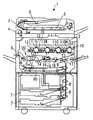
まず、図1にて、画像形成装置1における全体の構成・動作について説明する。
図1において、1は画像形成装置としてのタンデム型カラー複写機、2は入力画像情報に基づいたレーザ光を発する書込み部、3は原稿Dを原稿読込部4に搬送する原稿搬送部、4は原稿Dの画像情報を読み込む原稿読込部、6は定着工程後の記録媒体Pを搬送する搬送ローラ対、7は記録媒体P(用紙)が収容される給紙装置(給紙部)、9は記録媒体Pの搬送タイミングを調整するレジストローラ、11Y、11M、11C、11BKは各色(イエロー、マゼンタ、シアン、ブラック)のトナー像が形成される感光体ドラム、12は各感光体ドラム11Y、11M、11C、11BK上を帯電する帯電部、13は各感光体ドラム11Y、11M、11C、11BK上に形成される静電潜像を現像する現像部、14は各感光体ドラム11Y、11M、11C、11BK上に形成されたトナー像を記録媒体P上に重ねて転写する1次転写バイアスローラ、15は各感光体ドラム11Y、11M、11C、11BK上の未転写トナーを回収するクリーニング部、を示す。
First, the overall configuration and operation of the image forming apparatus 1 will be described with reference to FIG.
In FIG. 1, 1 is a tandem color copier as an image forming apparatus, 2 is a writing unit that emits laser light based on input image information, 3 is a document conveying unit that conveys a document D to a document reading unit 4, and 4 is An original reading unit for reading image information of the original D, 6 is a pair of conveyance rollers for conveying the recording medium P after the fixing process, 7 is a paper feeding device (paper feeding unit) in which the recording medium P (paper) is accommodated, and 9 is Registration rollers 11Y, 11M, 11C, and 11BK for adjusting the conveyance timing of the recording medium P are photosensitive drums on which toner images of the respective colors (yellow, magenta, cyan, and black) are formed, and 12 is the photosensitive drums 11Y and 11M. , 11C and 11BK are charged, 13 is a developing unit for developing the electrostatic latent image formed on each photoconductor drum 11Y, 11M, 11C, and 11BK, and 14 is each photoconductor drum 11Y. A primary transfer bias roller 15 for transferring the toner images formed on 11M, 11C, and 11BK to be superimposed on the recording medium P, and 15 is a cleaning that collects untransferred toner on the photosensitive drums 11Y, 11M, 11C, and 11BK. Part.

また、16は中間転写ベルト17を清掃する中間転写ベルトクリーニング部、17は複数色のトナー像が重ねて転写される中間転写ベルト、18は中間転写ベルト17上のカラートナー像を記録媒体P上に転写するための2次転写バイアスローラ、19は2次転写工程後の記録媒体Pを定着装置20に向けて搬送する搬送ベルト、20は記録媒体P上のトナー像(未定着画像)を定着するベルト方式の定着装置、80は両面プリントをおこなうときにオモテ面へのプリントが終了した記録媒体Pを画像形成部に向けて搬送する両面搬送部、を示す。   Reference numeral 16 denotes an intermediate transfer belt cleaning unit that cleans the intermediate transfer belt 17, 17 an intermediate transfer belt on which toner images of a plurality of colors are transferred and superimposed, and 18 a color toner image on the intermediate transfer belt 17 on the recording medium P. A secondary transfer bias roller 19 for transferring the toner image onto the recording medium P, a conveying belt 19 for conveying the recording medium P after the secondary transfer process toward the fixing device 20, and a toner image (unfixed image) on the recording medium P being fixed. A belt-type fixing device 80 is a double-sided conveyance unit that conveys the recording medium P that has been printed on the front side toward the image forming unit when performing double-sided printing.

以下、画像形成装置における、通常のカラー画像形成時の動作について説明する。
まず、原稿Dは、原稿搬送部3の搬送ローラによって、原稿台から図中の矢印方向に搬送されて、原稿読込部4のコンタクトガラス5上に載置される。そして、原稿読込部4で、コンタクトガラス5上に載置された原稿Dの画像情報が光学的に読み取られる。
Hereinafter, an operation during normal color image formation in the image forming apparatus will be described.
First, the document D is transported from the document table in the direction of the arrow in the drawing by the transport rollers of the document transport unit 3 and placed on the contact glass 5 of the document reading unit 4. Then, the document reading unit 4 optically reads the image information of the document D placed on the contact glass 5.

詳しくは、原稿読込部4は、コンタクトガラス5上の原稿Dの画像に対して、照明ランプから発した光を照射しながら走査させる。そして、原稿Dにて反射した光を、ミラー群及びレンズを介して、カラーセンサに結像する。原稿Dのカラー画像情報は、カラーセンサにてRGB(レッド、グリーン、ブルー)の色分解光ごとに読み取られた後に、電気的な画像信号に変換される。さらに、RGBの色分解画像信号をもとにして画像処理部で色変換処理、色補正処理、空間周波数補正処理等の処理をおこない、イエロー、マゼンタ、シアン、ブラックのカラー画像情報を得る。   Specifically, the document reading unit 4 scans the image of the document D on the contact glass 5 while irradiating light emitted from an illumination lamp. Then, the light reflected by the document D is imaged on the color sensor via the mirror group and the lens. The color image information of the document D is read for each RGB (red, green, blue) color separation light by the color sensor, and then converted into an electrical image signal. Further, color conversion processing, color correction processing, spatial frequency correction processing, and the like are performed by the image processing unit based on the RGB color separation image signals to obtain yellow, magenta, cyan, and black color image information.

そして、イエロー、マゼンタ、シアン、ブラックの各色の画像情報は、書込み部2に送信される。そして、書込み部2からは、各色の画像情報に基づいたレーザ光(露光光)が、それぞれ、対応する感光体ドラム11Y、11M、11C、11BK上に向けて発せられる。   Then, the image information of each color of yellow, magenta, cyan, and black is transmitted to the writing unit 2. The writing unit 2 emits laser light (exposure light) based on the image information of each color toward the corresponding photosensitive drums 11Y, 11M, 11C, and 11BK.

一方、4つの感光体ドラム11Y、11M、11C、11BKは、それぞれ、図1の反時計方向に回転している。そして、まず、感光体ドラム11Y、11M、11C、11BKの表面は、帯電部12との対向部で、一様に帯電される(帯電工程である。)。こうして、感光体ドラム11Y、11M、11C、11BK上には、帯電電位が形成される。その後、帯電された感光体ドラム11Y、11M、11C、11BKの表面は、それぞれのレーザ光の照射位置に達する。
書込み部2において、4つの光源から画像信号に対応したレーザ光が各色に対応してそれぞれ射出される。各レーザ光は、イエロー、マゼンタ、シアン、ブラックの色成分ごとに別の光路を通過することになる(露光工程である。)。
On the other hand, the four photosensitive drums 11Y, 11M, 11C, and 11BK are rotated counterclockwise in FIG. First, the surfaces of the photoconductor drums 11Y, 11M, 11C, and 11BK are uniformly charged at a portion facing the charging unit 12 (this is a charging process). Thus, a charged potential is formed on the photosensitive drums 11Y, 11M, 11C, and 11BK. Thereafter, the surfaces of the charged photosensitive drums 11Y, 11M, 11C, and 11BK reach the irradiation positions of the respective laser beams.
In the writing unit 2, laser light corresponding to the image signal is emitted from the four light sources corresponding to each color. Each laser beam passes through a separate optical path for each of the yellow, magenta, cyan, and black color components (this is an exposure process).

イエロー成分に対応したレーザ光は、紙面左側から1番目の感光体ドラム11Yの表面に照射される。このとき、イエロー成分のレーザ光は、高速回転するポリゴンミラーにより、感光体ドラム11Yの回転軸方向(主走査方向)に走査される。こうして、帯電部12にて帯電された後の感光体ドラム11Y上には、イエロー成分に対応した静電潜像が形成される。   The laser beam corresponding to the yellow component is applied to the surface of the first photosensitive drum 11Y from the left side of the paper. At this time, the yellow component laser light is scanned in the rotation axis direction (main scanning direction) of the photosensitive drum 11Y by a polygon mirror that rotates at high speed. Thus, an electrostatic latent image corresponding to the yellow component is formed on the photosensitive drum 11Y charged by the charging unit 12.

同様に、マゼンタ成分に対応したレーザ光は、紙面左から2番目の感光体ドラム11Mの表面に照射されて、マゼンタ成分に対応した静電潜像が形成される。シアン成分のレーザ光は、紙面左から3番目の感光体ドラム11Cの表面に照射されて、シアン成分の静電潜像が形成される。ブラック成分のレーザ光は、紙面左から4番目の感光体ドラム11BKの表面に照射されて、ブラック成分の静電潜像が形成される。   Similarly, the laser beam corresponding to the magenta component is irradiated on the surface of the second photosensitive drum 11M from the left side of the paper, and an electrostatic latent image corresponding to the magenta component is formed. The cyan component laser light is applied to the surface of the third photosensitive drum 11C from the left side of the drawing to form an electrostatic latent image of the cyan component. The black component laser light is applied to the surface of the fourth photoconductive drum 11BK from the left side of the drawing to form an electrostatic latent image of the black component.

その後、各色の静電潜像が形成された感光体ドラム11Y、11M、11C、11BKの表面は、それぞれ、現像部13との対向位置に達する。そして、各現像部13から感光体ドラム11Y、11M、11C、11BK上に各色のトナーが供給されて、感光体ドラム11Y、11M、11C、11BK上の潜像が現像される(現像工程である。)。
その後、現像工程後の感光体ドラム11Y、11M、11C、11BKの表面は、それぞれ、中間転写ベルト17との対向部に達する。ここで、それぞれの対向部には、中間転写ベルト17の内周面に当接するように1次転写バイアスローラ14が設置されている。そして、1次転写バイアスローラ14の位置で、中間転写ベルト17上に、感光体ドラム11Y、11M、11C、11BK上に形成された各色のトナー像が、順次重ねて転写される(1次転写工程である。)。
Thereafter, the surfaces of the photosensitive drums 11Y, 11M, 11C, and 11BK on which the electrostatic latent images of the respective colors are formed reach positions facing the developing unit 13, respectively. Then, the respective color toners are supplied from the developing units 13 onto the photosensitive drums 11Y, 11M, 11C, and 11BK, and the latent images on the photosensitive drums 11Y, 11M, 11C, and 11BK are developed (development process). .)
Thereafter, the surfaces of the photoconductive drums 11Y, 11M, 11C, and 11BK after the development process reach the facing portions of the intermediate transfer belt 17, respectively. Here, a primary transfer bias roller 14 is installed at each facing portion so as to be in contact with the inner peripheral surface of the intermediate transfer belt 17. Then, the toner images of the respective colors formed on the photosensitive drums 11Y, 11M, 11C, and 11BK are sequentially superimposed and transferred onto the intermediate transfer belt 17 at the position of the primary transfer bias roller 14 (primary transfer). Process.)

そして、転写工程後の感光体ドラム11Y、11M、11C、11BKの表面は、それぞれ、クリーニング部15との対向位置に達する。そして、クリーニング部15で、感光体ドラム11Y、11M、11C、11BK上に残存する未転写トナーが回収される(クリーニング工程である。)。
その後、感光体ドラム11Y、11M、11C、11BKの表面は、除電部を通過して、感光体ドラム11Y、11M、11C、11BKにおける一連の作像プロセスが終了する。
Then, the surfaces of the photoconductive drums 11Y, 11M, 11C, and 11BK after the transfer process reach positions facing the cleaning unit 15, respectively. Then, the untransferred toner remaining on the photosensitive drums 11Y, 11M, 11C, and 11BK is collected by the cleaning unit 15 (this is a cleaning process).
Thereafter, the surfaces of the photoconductive drums 11Y, 11M, 11C, and 11BK pass through the static eliminating unit, and a series of image forming processes in the photoconductive drums 11Y, 11M, 11C, and 11BK is completed.

他方、感光体ドラム11Y、11M、11C、11BK上の各色のトナーが重ねて転写(担持)された中間転写ベルト17は、図中の時計方向に走行して、2次転写バイアスローラ18との対向位置に達する。そして、2次転写バイアスローラ18との対向位置で、記録媒体P上に中間転写ベルト17上に担持されたカラーのトナー像が転写される(2次転写工程である。)。
その後、中間転写ベルト17の表面は、中間転写ベルトクリーニング部16の位置に達する。そして、中間転写ベルト17上に付着した未転写トナーが中間転写ベルトクリーニング部16に回収されて、中間転写ベルト17における一連の転写プロセスが終了する。
On the other hand, the intermediate transfer belt 17 on which the toners of the respective colors on the photosensitive drums 11Y, 11M, 11C, and 11BK are transferred (carrying) are run in the clockwise direction in the drawing and are connected to the secondary transfer bias roller 18. Reach the opposite position. Then, a color toner image carried on the intermediate transfer belt 17 is transferred onto the recording medium P at a position facing the secondary transfer bias roller 18 (secondary transfer step).
Thereafter, the surface of the intermediate transfer belt 17 reaches the position of the intermediate transfer belt cleaning unit 16. Then, the untransferred toner adhered on the intermediate transfer belt 17 is collected by the intermediate transfer belt cleaning unit 16, and a series of transfer processes in the intermediate transfer belt 17 is completed.

ここで、中間転写ベルト17と2次転写バイアスローラ18との間(2次転写ニップである。)に搬送される記録媒体Pは、給紙装置7からレジストローラ9等を経由して搬送されたものである。
詳しくは、記録媒体Pを収納する給紙装置7から、給紙ローラ8により給送された記録媒体Pが、搬送ガイドを通過した後に、レジストローラ9に導かれる。レジストローラ9(タイミングローラ)に達した記録媒体Pは、タイミングを合わせて、2次転写ニップに向けて搬送される。
Here, the recording medium P conveyed between the intermediate transfer belt 17 and the secondary transfer bias roller 18 (secondary transfer nip) is conveyed from the paper feeding device 7 via the registration roller 9 and the like. It is a thing.
Specifically, the recording medium P fed by the paper feeding roller 8 from the paper feeding device 7 that stores the recording medium P is guided to the registration roller 9 after passing through the conveyance guide. The recording medium P that has reached the registration roller 9 (timing roller) is conveyed toward the secondary transfer nip at the same timing.

そして、フルカラー画像が転写された記録媒体Pは、搬送ベルト19によって定着装置20に導かれる。定着装置20では、定着ベルトと加圧ローラとのニップ部にて、カラー画像(トナー)が記録媒体P上に定着される(定着工程である。)。
そして、定着工程後の記録媒体Pは、搬送ローラ対6によって搬送された後に、排紙ローラ対によって装置本体1外に出力画像として排出されて、一連の画像形成プロセスが完了する。
Then, the recording medium P on which the full color image is transferred is guided to the fixing device 20 by the transport belt 19. In the fixing device 20, a color image (toner) is fixed on the recording medium P at the nip portion between the fixing belt and the pressure roller (this is a fixing step).
Then, after the fixing process, the recording medium P is transported by the transport roller pair 6 and then discharged as an output image to the outside of the apparatus main body 1 by the paper discharge roller pair, thereby completing a series of image forming processes.

なお、記録媒体Pの両面(オモテ面とウラ面とである。)へのプリントをおこなう「両面プリントモード」が選択されている場合には、オモテ面への定着工程が終了した記録媒体Pは、そのまま排紙されることなく、両面搬送部80に導かれて、そこで搬送方向が反転された後に、再び2次転写バイアスローラ18の位置に向けて搬送される。そして、2次転写バイアスローラ18の位置で先に説明したものと同様の作像プロセスによって記録媒体Pのウラ面への画像形成がおこなわれ、その後に定着装置20での定着工程を経て、搬送ローラ対6で搬送された後に、排紙ローラ対によって装置本体1外に出力画像として排出される。   Note that when “double-sided printing mode” for performing printing on both sides (front side and back side) of the recording medium P is selected, the recording medium P that has completed the fixing process on the front side is The paper is not discharged as it is, but is guided to the double-sided conveyance unit 80 where the conveyance direction is reversed and then conveyed toward the position of the secondary transfer bias roller 18 again. Then, an image is formed on the back surface of the recording medium P by the image forming process similar to that described above at the position of the secondary transfer bias roller 18, and then the image is conveyed through a fixing process in the fixing device 20. After being conveyed by the roller pair 6, the paper is discharged as an output image outside the apparatus main body 1 by the paper discharge roller pair.

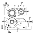
次に、図2にて、画像形成装置本体1に設置される定着装置20の構成・動作について詳述する。
図2に示すように、定着装置20は、定着補助ローラ22、加熱ローラ23、定着回転体としての定着ベルト21、テンションローラ24、加圧回転体としての加圧ローラ31、定着ベルト21用の温度センサ40、加圧ローラ用の温度センサ45(温度検知手段)、入口ガイド板34、出口ガイド板35、冷却機構50〜52、整風板55、56、移動機構60(図3を参照できる。)、等で構成される。
Next, the configuration / operation of the fixing device 20 installed in the image forming apparatus main body 1 will be described in detail with reference to FIG.
As shown in FIG. 2, the fixing device 20 includes a fixing auxiliary roller 22, a heating roller 23, a fixing belt 21 as a fixing rotator, a tension roller 24, a pressure roller 31 as a pressure rotator, and a fixing belt 21. The temperature sensor 40, the pressure sensor 45 for the pressure roller (temperature detecting means), the inlet guide plate 34, the outlet guide plate 35, the cooling mechanisms 50 to 52, the air conditioning plates 55 and 56, and the moving mechanism 60 (see FIG. 3). ), Etc.

ここで、定着回転体としての定着ベルト21は、樹脂材料からなるベース層上に、弾性層、離型層が順次積層された多層構造の無端状ベルトである。定着ベルト21の弾性層は、フッ素ゴム、シリコーンゴム、発泡性シリコーンゴム等の弾性材料で形成されている。定着ベルト21の離型層は、PFA(4フッ化エチレンバーフルオロアルキルビニルエーテル共重合体樹脂)、ポリイミド、ポリエーテルイミド、PES(ポリエーテルサルファイド)、等で形成されている。定着ベルト21の表層に離型層を設けることにより、トナー(トナー像)に対する離型性(剥離性)が担保されることになる。定着ベルト21は、3つのローラ(定着補助ローラ22と加熱ローラ23とテンションローラ24とである。)に張架・支持されて、図2中の矢印方向に走行(回転)する。テンションローラ24は、定着ベルト21の内周面に当接していて、定着ベルト21に所定の張力を与えている。定着回転体として熱容量の低い定着ベルト21を用いることで、装置の昇温特性が向上する。   Here, the fixing belt 21 as a fixing rotating body is an endless belt having a multilayer structure in which an elastic layer and a release layer are sequentially laminated on a base layer made of a resin material. The elastic layer of the fixing belt 21 is formed of an elastic material such as fluorine rubber, silicone rubber, or foamable silicone rubber. The release layer of the fixing belt 21 is formed of PFA (tetrafluoroethylene barfluoroalkyl vinyl ether copolymer resin), polyimide, polyetherimide, PES (polyether sulfide), or the like. By providing the release layer on the surface layer of the fixing belt 21, the releasability (peelability) for the toner (toner image) is secured. The fixing belt 21 is stretched and supported by three rollers (a fixing auxiliary roller 22, a heating roller 23, and a tension roller 24), and travels (rotates) in the direction of the arrow in FIG. The tension roller 24 is in contact with the inner peripheral surface of the fixing belt 21 and applies a predetermined tension to the fixing belt 21. By using the fixing belt 21 having a low heat capacity as the fixing rotator, the temperature rise characteristic of the apparatus is improved.

定着補助ローラ22は、SUS304等の芯金22a上に、層厚が15mm程度の発泡シリコーンゴムからなる弾性層22b(アスカーC硬度が25〜50程度のものである。)が形成されたローラであって、加圧回転体としての加圧ローラ31に定着ベルト21を介して圧接してニップ部を形成する。弾性層22bを発泡材料で形成することで、ニップ部におけるニップ幅(ニップ量)を比較的大きく設定できるとともに、定着ベルト21の熱が定着補助ローラ22に移行しにくくなる。定着補助ローラ22は、その軸部が駆動モータに連結されていて、図2中の時計方向に回転駆動される。
なお、本実施の形態では、弾性層22bの材料として発泡シリコーンゴムを用いたが、弾性層22bの材料としてフッ素ゴム、シリコーンゴム等を用いることもできる。
The fixing auxiliary roller 22 is a roller in which an elastic layer 22b (having an Asker C hardness of about 25 to 50) made of foamed silicone rubber having a layer thickness of about 15 mm is formed on a core metal 22a such as SUS304. Thus, a nip portion is formed by pressing the pressure roller 31 as a pressure rotator through the fixing belt 21. By forming the elastic layer 22b from a foamed material, the nip width (nip amount) at the nip portion can be set relatively large, and the heat of the fixing belt 21 is difficult to transfer to the auxiliary fixing roller 22. The shaft portion of the auxiliary fixing roller 22 is connected to a drive motor and is driven to rotate clockwise in FIG.
In the present embodiment, foamed silicone rubber is used as the material of the elastic layer 22b. However, fluorine rubber, silicone rubber, or the like can be used as the material of the elastic layer 22b.

加熱ローラ23は、アルミニウム等の熱伝導率の高い金属材料からなる中空構造のローラであって、その円筒体の内部には加熱手段としてのヒータ25(熱源)が固設されている。なお、加熱ローラ23は、耐食性を向上させるために、その表面にアルマイト処理が施されている。
加熱ローラ23のヒータ25は、ハロゲンヒータであって、その両端部が定着装置20の側板に固定されている。そして、装置本体1に設置された電源部(交流電源)により出力制御されたヒータ25からの輻射熱によって加熱ローラ23が加熱されて、さらに加熱ローラ23によって加熱された定着ベルト21の表面から記録媒体P上のトナー像に熱が加えられる。ヒータ25(加熱手段)の出力制御は、定着ベルト21の表面に非接触で対向する温度センサ40(サーモパイル)によるベルト表面温度の検知結果に基づいておこなわれる。詳しくは、温度センサ40の検知結果に基づいて定められる通電時間だけ、電源部からヒータ25に交流電圧が印加される。このようなヒータ25の出力制御によって、定着ベルト21の温度(定着温度)を所望の温度(目標制御温度)に調整制御することができる。
The heating roller 23 is a hollow roller made of a metal material having high thermal conductivity such as aluminum, and a heater 25 (heat source) as a heating unit is fixed inside the cylindrical body. The surface of the heating roller 23 is anodized to improve the corrosion resistance.
The heater 25 of the heating roller 23 is a halogen heater, and both ends thereof are fixed to the side plate of the fixing device 20. Then, the heating roller 23 is heated by the radiant heat from the heater 25 whose output is controlled by the power supply unit (AC power supply) installed in the apparatus main body 1, and further, the recording medium starts from the surface of the fixing belt 21 heated by the heating roller 23. Heat is applied to the toner image on P. The output control of the heater 25 (heating means) is performed based on the detection result of the belt surface temperature by the temperature sensor 40 (thermopile) that faces the surface of the fixing belt 21 in a non-contact manner. Specifically, the AC voltage is applied to the heater 25 from the power supply unit for the energization time determined based on the detection result of the temperature sensor 40. By such output control of the heater 25, the temperature (fixing temperature) of the fixing belt 21 can be adjusted and controlled to a desired temperature (target control temperature).

また、加圧回転体としての加圧ローラ31は、主として、芯金32と、芯金32の外周面に接着層を介して形成された弾性層33(層厚が比較的厚く設定されたものである。)と、からなる。加圧ローラ31の弾性層33は、フッ素ゴム、シリコーンゴム等のソリッドゴム材料で形成されている。そして、加圧ローラ31は、定着ベルト21を介して定着補助ローラ22に圧接する。こうして、加圧ローラ31と定着ベルト21との間に、所望のニップ部(定着ニップ部)が形成される。
なお、弾性層33の表層にPFA等からなる薄肉の離型層を設けることもできる。また、加圧ローラ31の外周面にシリコーンオイルなどが含浸されたクリーニングローラを摺接させることもできる。
The pressure roller 31 as a pressure rotator is mainly composed of a cored bar 32 and an elastic layer 33 formed on the outer peripheral surface of the cored bar 32 via an adhesive layer (with a relatively thick layer thickness). ). The elastic layer 33 of the pressure roller 31 is formed of a solid rubber material such as fluorine rubber or silicone rubber. The pressure roller 31 is in pressure contact with the auxiliary fixing roller 22 via the fixing belt 21. Thus, a desired nip (fixing nip) is formed between the pressure roller 31 and the fixing belt 21.
A thin release layer made of PFA or the like can be provided on the surface layer of the elastic layer 33. Further, a cleaning roller in which silicone oil or the like is impregnated on the outer peripheral surface of the pressure roller 31 can be brought into sliding contact.

図2を参照して、定着ベルト21と加圧ローラ31との当接部(ニップ部である。)の入口側には、記録媒体Pのニップ部に向けての搬送を案内する入口ガイド板34が配設されている。
また、定着ベルト21と加圧ローラ31とのニップ部の出口側(ニップ部に対して搬送方向下流側の位置)には、ニップ部から送出された記録媒体Pの搬送を案内する出口ガイド板35が配設されている。
Referring to FIG. 2, an inlet guide plate that guides the conveyance of the recording medium P toward the nip portion on the inlet side of the contact portion (nip portion) between the fixing belt 21 and the pressure roller 31. 34 is arranged.
An exit guide plate that guides the conveyance of the recording medium P sent from the nip portion on the outlet side of the nip portion between the fixing belt 21 and the pressure roller 31 (a position downstream in the conveyance direction with respect to the nip portion). 35 is disposed.

図3を参照して、移動機構60(接離機構)は、定着ベルト21(定着回転体)に対して加圧ローラ31(加圧回転体)を接離方向(図2の白矢印方向である。)に移動させるものである。すなわち、移動機構60を動作させて、定着工程をおこなうための所望のニップ部が形成されるように図2に示すように定着ベルト21(定着補助ローラ22)に対して加圧ローラ31を所定のニップ圧で当接させたり、図3に示すように定着ベルト21(定着補助ローラ22)に対して加圧ローラ31を離間させたり(又は、ニップ圧を減じたり)、する。
図3に示すような、加圧ローラ31を離間させる動作(又は、ニップ圧を減ずる動作)は、非画像形成時(非定着工程時)におこなわれる。すなわち、画像形成時(定着工程時)には図2に示すように加圧ローラ31を当接状態にして、非画像形成時(非定着工程時)には図3に示すように加圧ローラ31を離間状態にするように、移動機構60を制御することになる。このように動作する移動機構60(接離機構)としては、制御部によって制御されるモータ駆動によって加圧ローラ31を上下動させるカム機構を用いたものなど、公知のものを用いることができる。
このように構成・動作することにより、定着装置20が稼働停止した状態で加圧ローラ31の当接状態が長時間続いて、定着補助ローラ22の弾性層22bや、加圧ローラ31の弾性層33に、永久歪が生じてしまう不具合を防止することができる。
なお、本実施の形態における定着装置20には、冷却機構50〜52や整風板55、56や加圧ローラ用の温度センサ45(温度検知手段)が設置されているが、これらについては後で詳しく説明する。
Referring to FIG. 3, the moving mechanism 60 (contacting / separating mechanism) moves the pressure roller 31 (pressure rotating body) toward and away from the fixing belt 21 (fixing rotating body) in the direction indicated by the white arrow in FIG. Yes.) That is, by operating the moving mechanism 60, the pressure roller 31 is set against the fixing belt 21 (fixing auxiliary roller 22) as shown in FIG. 2 so that a desired nip portion for performing the fixing process is formed. The pressure roller 31 is separated from the fixing belt 21 (fixing auxiliary roller 22) (or the nip pressure is reduced) as shown in FIG.
The operation of separating the pressure roller 31 (or the operation of reducing the nip pressure) as shown in FIG. 3 is performed during non-image formation (non-fixing process). That is, the pressure roller 31 is brought into contact as shown in FIG. 2 at the time of image formation (fixing step), and the pressure roller as shown in FIG. 3 at the time of non-image formation (non-fixing step). The moving mechanism 60 is controlled so that 31 is in the separated state. As the moving mechanism 60 (contact / separation mechanism) that operates in this manner, a known mechanism such as a mechanism that uses a cam mechanism that moves the pressure roller 31 up and down by motor driving controlled by a control unit can be used.
By configuring and operating in this way, the contact state of the pressure roller 31 continues for a long time with the fixing device 20 stopped operating, and the elastic layer 22b of the auxiliary fixing roller 22 or the elastic layer of the pressure roller 31. 33 can prevent a problem that permanent distortion occurs.
The fixing device 20 according to the present embodiment is provided with cooling mechanisms 50 to 52, air conditioning plates 55 and 56, and a temperature sensor 45 (temperature detection means) for the pressure roller. explain in detail.

以下、定着装置20の、通常の通紙時の動作について説明する。
装置本体1の電源スイッチが投入されると、電源部からヒータ25に交流電圧が印加(給電)されるとともに、駆動モータによって定着補助ローラ22が回転駆動されて、それぞれの部材同士の摩擦抵抗によって定着ベルト21、加熱ローラ23、加圧ローラ31が図2中の矢印方向に回転(従動)する。
その後、給紙装置7から記録媒体Pが給送されて、2次転写バイアスローラ18の位置でトナー像が記録媒体P上に未定着画像として担持される。未定着画像(トナー像)が担持された記録媒体Pは、図2の一点鎖線の矢印方向に搬送されて、圧接状態にある定着ベルト21及び加圧ローラ31のニップ部に送入される。そして、定着ベルト21による加熱と、定着ベルト21(定着補助ローラ22)及び加圧ローラ31の押圧力とによって、記録媒体Pの表面にトナー像が定着される。その後、回転する定着ベルト21及び加圧ローラ31によってそのニップ部から送出された記録媒体Pは、出口ガイド板35に案内されながら一点鎖線の矢印方向に搬送される。
Hereinafter, the operation of the fixing device 20 during normal paper feeding will be described.
When the power switch of the apparatus main body 1 is turned on, an AC voltage is applied (powered) from the power supply unit to the heater 25, and the fixing auxiliary roller 22 is rotationally driven by the drive motor, and frictional resistance between the respective members The fixing belt 21, the heating roller 23, and the pressure roller 31 rotate (follow) in the direction of the arrow in FIG.
Thereafter, the recording medium P is fed from the sheet feeding device 7, and the toner image is carried on the recording medium P as an unfixed image at the position of the secondary transfer bias roller 18. The recording medium P carrying an unfixed image (toner image) is conveyed in the direction of the dashed line in FIG. 2 and fed into the nip portion of the fixing belt 21 and the pressure roller 31 that are in a pressure contact state. The toner image is fixed on the surface of the recording medium P by the heating by the fixing belt 21 and the pressing force of the fixing belt 21 (fixing auxiliary roller 22) and the pressure roller 31. Thereafter, the recording medium P sent out from the nip portion by the rotating fixing belt 21 and the pressure roller 31 is conveyed in the direction of the dashed line arrow while being guided by the exit guide plate 35.

以下、本実施の形態における定着装置20の、特徴的な構成・動作について説明する。
図2、図3等を参照して、本実施の形態における定着装置20には、加圧ローラ31(加圧回転体)の外周面に空気を当てて、その外周面を冷却(空冷)する冷却機構50〜52が設けられている。
この冷却機構は、図2、図3に示すように、送風機50(ブロア)、ダクト51(冷却ダクト)、排気ダクト52、等で構成されている。
送風機50(ブロア)は、定着装置20の外部から空気を吸引するものであって、吸引した空気を吐出する吐出口にはダクト51が接続されている。ダクト51は、送風機50から吐出された空気を加圧ローラ31の外周面(図2、図3の右斜め下方の表面である。)に直接的に当てて、その後に加圧ローラ31の外周面(表面)に沿って空気が図2、図3の左方に流動するように構成されている。また、排気ダクト52は、ダクト51に沿って流動した空気を、定着装置20の下方に形成した排気口52aから排出するように、構成されている。すなわち、冷却機構50〜52によって、空気が図2、図3の黒矢印方向に流動して、加圧ローラ31の表面温度が過剰に上昇しないように加圧ローラ31を空冷している。
Hereinafter, a characteristic configuration and operation of the fixing device 20 in the present embodiment will be described.
Referring to FIGS. 2, 3, etc., in fixing device 20 in the present embodiment, air is applied to the outer peripheral surface of pressure roller 31 (pressure rotating body) to cool (air-cool) the outer peripheral surface. Cooling mechanisms 50 to 52 are provided.
As shown in FIGS. 2 and 3, the cooling mechanism includes a blower 50 (blower), a duct 51 (cooling duct), an exhaust duct 52, and the like.
The blower 50 (blower) sucks air from the outside of the fixing device 20, and a duct 51 is connected to a discharge port for discharging the sucked air. The duct 51 directly applies the air discharged from the blower 50 to the outer peripheral surface of the pressure roller 31 (the surface on the lower right side in FIGS. 2 and 3), and then the outer periphery of the pressure roller 31. Air is configured to flow to the left in FIGS. 2 and 3 along the surface (surface). Further, the exhaust duct 52 is configured to discharge air flowing along the duct 51 from an exhaust port 52 a formed below the fixing device 20. That is, the pressure rollers 31 are air-cooled by the cooling mechanisms 50 to 52 so that the air flows in the black arrow direction of FIGS. 2 and 3 and the surface temperature of the pressure roller 31 does not rise excessively.

このように、本実施の形態では、冷却機構50〜52を設けて、加圧ローラ31の外周面(表面)を空冷しているため、加圧ローラ31の表面温度が上昇してホットオフセット画像が生じたり加圧ローラ31が熱膨張や熱劣化したりする不具合が確実に軽減されることになる。
特に、本実施の形態では、記録媒体Pとして封筒が通紙された場合であっても記録媒体P(封筒)にシワやズレが生じないように、加圧ローラ31の弾性層33の層厚が比較的厚くなるように設定していて、加圧ローラ31が熱膨張しやすい構成になっているため、冷却機構50〜52による冷却が有用になる。
また、本実施の形態では、加圧ローラ31が当接状態(図2の状態である。)にあるときに加えて、加圧ローラ31が離間状態(図3の状態である。)にあるときにも、冷却機構50〜52によって加圧ローラ31を空冷できるように構成しているため、より自由度の高い空冷制御が可能になる。例えば、離間状態において、画像形成(定着工程)がおこなわれる前に、温度センサ45によって加圧ローラ31の温度が所定値よりも大きくて良好な定着工程がおこなわれないものと判別されたときに、離間状態時においても加圧ローラ31を冷却機構50〜52によって空冷するように制御することもできる。
Thus, in this embodiment, since the cooling mechanisms 50 to 52 are provided and the outer peripheral surface (surface) of the pressure roller 31 is air-cooled, the surface temperature of the pressure roller 31 rises to cause a hot offset image. Inconvenience that the pressure roller 31 is thermally expanded or deteriorated is surely reduced.
In particular, in the present embodiment, even when an envelope is passed as the recording medium P, the layer thickness of the elastic layer 33 of the pressure roller 31 does not cause wrinkles or displacement on the recording medium P (envelope). Is set to be relatively thick, and the pressure roller 31 is configured to easily thermally expand, so that cooling by the cooling mechanisms 50 to 52 is useful.
Further, in the present embodiment, in addition to when the pressure roller 31 is in the contact state (the state shown in FIG. 2), the pressure roller 31 is in the separated state (the state shown in FIG. 3). In some cases, the pressure roller 31 can be air-cooled by the cooling mechanisms 50 to 52, so that air-cooling control with a higher degree of freedom is possible. For example, in the separated state, when the temperature sensor 45 determines that the temperature of the pressure roller 31 is higher than a predetermined value and the favorable fixing process is not performed before the image formation (fixing process) is performed. Even in the separated state, the pressure roller 31 can be controlled to be air-cooled by the cooling mechanisms 50 to 52.

ここで、本実施の形態において、図4に示すように、冷却機構50〜52は、加圧ローラ31の幅方向(図2、図3の紙面垂直方向であって、加圧ローラ31の回転軸方向である。)の複数箇所をそれぞれ別々に冷却できるように構成されている。また、加圧ローラ31の表面温度を検知する温度検知手段としての温度センサ45も、加圧ローラ31の幅方向の複数箇所の温度をそれぞれ別々に検知できるように構成されている。   Here, in the present embodiment, as shown in FIG. 4, the cooling mechanisms 50 to 52 are arranged in the width direction of the pressure roller 31 (the direction perpendicular to the paper surface of FIGS. 2 and 3, and the rotation of the pressure roller 31. A plurality of locations in the axial direction) can be cooled separately. Further, the temperature sensor 45 as temperature detecting means for detecting the surface temperature of the pressure roller 31 is also configured to be able to separately detect temperatures at a plurality of locations in the width direction of the pressure roller 31.

詳しくは、図4を参照して、本実施の形態における定着装置20には、加圧ローラ31(加圧回転体)の表面温度を幅方向の複数箇所(本実施の形態では3箇所である。)でそれぞれ検知する複数の温度検知手段としての温度センサ45A〜45Cが設けられている。
さらに具体的に、これらの温度センサ45A〜45Cは、加圧ローラ31の表面に非接触で対向するサーモパイルであって、第1温度センサ45Aは加圧ローラ31の幅方向一端側の温度を検知して、第2温度センサ45Bは加圧ローラ31の幅方向中央部の温度を検知して、第3温度センサ45Cは加圧ローラ31の幅方向他端側の温度を検知する。
Specifically, referring to FIG. 4, in fixing device 20 in the present embodiment, the surface temperature of pressure roller 31 (pressure rotator) is set at a plurality of locations in the width direction (three locations in the present embodiment). .) Are provided with a plurality of temperature sensors 45A to 45C as temperature detecting means.
More specifically, these temperature sensors 45 </ b> A to 45 </ b> C are thermopiles that face the surface of the pressure roller 31 in a non-contact manner, and the first temperature sensor 45 </ b> A detects the temperature of one end in the width direction of the pressure roller 31. Then, the second temperature sensor 45B detects the temperature of the central portion in the width direction of the pressure roller 31, and the third temperature sensor 45C detects the temperature of the other end in the width direction of the pressure roller 31.

そして、図4を参照して、冷却機構は、上述した複数の温度センサ45A〜45C(温度検知手段)の検知結果に基づいて、加圧ローラ31の表面に対して複数の温度センサ45A〜45Cの設置位置に対応した幅方向の複数箇所にそれぞれ別々に空気を当てられるように構成されている。
さらに具体的に、図4を参照して、第1送風機50Aは外部から吸引した空気を第1ダクト51A(仕切部材59によって隣接する第2ダクト51Bに対して隔絶されている。)に吐出して、第1ダクト51Aを介して加圧ローラ31の幅方向一端側に空気が当てられることになる。同様に、第2送風機50Bは外部から吸引した空気を第2ダクト51B(仕切部材59によって隣接する第1、第3ダクト51A、51Cに対して隔絶されている。)に吐出して、第2ダクト51Bを介して加圧ローラ31の幅方向中央部に空気が当てられることになる。同様に、第3送風機50Cは外部から吸引した空気を第3ダクト51C(仕切部材59によって隣接する第2ダクト51Bに対して隔絶されている。)に吐出して、第3ダクト51Cを介して加圧ローラ31の幅方向他端側に空気が当てられることになる。
Referring to FIG. 4, the cooling mechanism includes a plurality of temperature sensors 45 </ b> A to 45 </ b> C with respect to the surface of the pressure roller 31 based on the detection results of the plurality of temperature sensors 45 </ b> A to 45 </ b> C (temperature detection means) described above. The air can be separately applied to a plurality of positions in the width direction corresponding to the installation positions of the two.
More specifically, referring to FIG. 4, first blower 50 </ b> A discharges air sucked from the outside into first duct 51 </ b> A (isolated from adjacent second duct 51 </ b> B by partition member 59). Thus, air is applied to one end in the width direction of the pressure roller 31 via the first duct 51A. Similarly, the second blower 50B discharges air sucked from the outside to the second duct 51B (isolated from the first and third ducts 51A and 51C adjacent to each other by the partition member 59), and then the second blower 50B. Air is applied to the central portion in the width direction of the pressure roller 31 through the duct 51B. Similarly, the third blower 50C discharges air sucked from the outside to the third duct 51C (isolated from the adjacent second duct 51B by the partition member 59), and passes through the third duct 51C. Air is applied to the other end in the width direction of the pressure roller 31.

そして、第1温度センサ45Aによって加圧ローラ31の幅方向一端側の温度が所定値以上になった状態が検知されると、そのままでは良好な定着工程がおこなわれないものとして、その検知温度が所定値未満になるまで第1送風機50Aを稼働する。同様に、第2温度センサ45Bによって加圧ローラ31の幅方向中央部の温度が所定値以上になった状態が検知されると、そのままでは良好な定着工程がおこなわれないものとして、その検知温度が所定値未満になるまで第2送風機50Bを稼働する。同様に、第3温度センサ45Cによって加圧ローラ31の幅方向他端側の温度が所定値以上になった状態が検知されると、そのままでは良好な定着工程がおこなわれないものとして、その検知温度が所定値未満になるまで第3送風機50Cを稼働する。
このように構成・動作することにより、加圧ローラ31における幅方向の一部が局所的に過昇温してしまうような場合であっても、そのような状態を解消して、加圧ローラ31の表面温度を幅方向にわたって均一化することができる。例えば、小サイズ紙(加圧ローラ31の幅方向両端部が非通紙領域となる記録媒体Pである。)を連続通紙するような場合、非通紙領域では記録媒体Pへの熱移動が生じないため、加圧ローラ31の幅方向両端部のみが過昇温しやすくなるが、第1、第3送風機50A、50Cを稼働して加圧ローラ31の幅方向両端部を空冷することで、そのような不具合を防止することができる。
なお、送風機50や温度センサ45の数は、本実施の形態における3個に限定されることなく、通紙可能な記録媒体Pの幅方向サイズの数に応じて増減することもできる。
When the first temperature sensor 45A detects that the temperature at one end in the width direction of the pressure roller 31 is equal to or higher than a predetermined value, it is assumed that a good fixing process is not performed as it is, and the detected temperature is The first blower 50A is operated until it becomes less than the predetermined value. Similarly, when the second temperature sensor 45B detects that the temperature of the central portion in the width direction of the pressure roller 31 is equal to or higher than a predetermined value, it is assumed that a good fixing process is not performed as it is, and the detected temperature The second blower 50B is operated until becomes less than a predetermined value. Similarly, if the third temperature sensor 45C detects that the temperature at the other end in the width direction of the pressure roller 31 is equal to or higher than a predetermined value, it is assumed that a good fixing process is not performed as it is. The third blower 50C is operated until the temperature becomes lower than a predetermined value.
By configuring and operating in this way, even if a part of the pressure roller 31 in the width direction locally overheats, such a state is eliminated, and the pressure roller The surface temperature of 31 can be made uniform over the width direction. For example, when small-size paper (the recording medium P in which both end portions in the width direction of the pressure roller 31 are non-passing areas) is continuously passed, heat transfer to the recording medium P is performed in the non-passing area. However, only the both ends in the width direction of the pressure roller 31 easily overheat, but the first and third blowers 50A and 50C are operated to air-cool both ends in the width direction of the pressure roller 31. Thus, such a problem can be prevented.
Note that the number of blowers 50 and temperature sensors 45 is not limited to three in the present embodiment, and can be increased or decreased according to the number of sizes in the width direction of the recording medium P that can be passed.

ここで、図2、図3等を参照して、本実施の形態における定着装置20には、加圧ローラ31(加圧回転体)の外周面に当てられた後の空気が流れる方向や量を制限(制御)する第1の整風板55(第1整風板)と、加圧ローラ31の外周面に当てられる前の空気が流れる方向や量を制限する第2の整風板56(第2整風板)と、がそれぞれ冷却機構の一部として設けられている。
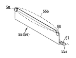
図5等を参照して、これらの整風板55、56は、いずれも、金属材料、又は、耐熱性を有する樹脂材料、で形成された略板状の部材である。
第1の整風板55は、送風機50から吐出されてダクト51を通過した空気が加圧ローラ31の表面に直接当てられる位置に対して、加圧ローラ31の回転方向上流側の位置(図2、図3において、加圧ローラ31の左斜め下方の位置である。)に微小な隙間G(図6を参照できる。)をあけて対向して、ダクト51と排気ダクト52との間に隙間が生じないように構成されている。このように整風板55を設けることで、加圧ローラ31の表面に当てられた後の空気が、ダクト51と排気ダクト52と加圧ローラ31との間からほとんど漏れることなく、図2、図3にて黒矢印で示す流れに沿って、排気ダクト52にスムーズに導かれて排気口52aから効率的に排出されることになる。特に、加圧ローラ31の表面に沿って流動する空気が、整風板55によって、その表面から離れるように、その流れ方向が可変されることになる。
第2の整風板56は、送風機50から吐出されてダクト51を通過した空気が加圧ローラ31の表面に直接当てられる位置の近傍において、加圧ローラ31に対して微小な隙間をあけて対向して、ダクト51との間に隙間が生じないように構成されている。このように第2の整風板55を設けることで、加圧ローラ31の表面に当てられる前の空気が、ダクト51と加圧ローラ31との間からほとんど漏れることなく、図2、図3にて黒矢印で示す流れに沿って空気がスムーズに流れることになる。
Here, with reference to FIG. 2, FIG. 3, etc., in the fixing device 20 in the present embodiment, the direction and amount of air flow after being applied to the outer peripheral surface of the pressure roller 31 (pressure rotating body). The first air conditioning plate 55 (first air conditioning plate) that restricts (controls) the air and the second air conditioning plate 56 (second airflow) that restricts the direction and amount of air before being applied to the outer peripheral surface of the pressure roller 31. And a wind control plate) are provided as part of the cooling mechanism.
With reference to FIG. 5 etc., these air-conditioning plates 55 and 56 are both substantially plate-like members formed of a metal material or a heat-resistant resin material.
The first air conditioning plate 55 is positioned upstream of the pressure roller 31 in the rotation direction with respect to the position where the air discharged from the blower 50 and passed through the duct 51 is directly applied to the surface of the pressure roller 31 (FIG. 2). In FIG. 3, it is a position diagonally to the left of the pressure roller 31), and is opposed to the gap 51 between the duct 51 and the exhaust duct 52 with a small gap G (see FIG. 6) therebetween. Is configured not to occur. By providing the air conditioning plate 55 in this way, the air after being applied to the surface of the pressure roller 31 hardly leaks from between the duct 51, the exhaust duct 52, and the pressure roller 31, and FIG. 3, the air is smoothly guided to the exhaust duct 52 along the flow indicated by the black arrow and efficiently discharged from the exhaust port 52 a. In particular, the flow direction of the air flowing along the surface of the pressure roller 31 is changed by the air conditioning plate 55 so that the air flows away from the surface.
The second air conditioning plate 56 faces the pressure roller 31 with a minute gap in the vicinity of the position where the air discharged from the blower 50 and passed through the duct 51 is directly applied to the surface of the pressure roller 31. And it is comprised so that a clearance gap may not arise between the ducts 51. FIG. By providing the second air conditioning plate 55 in this way, the air before being applied to the surface of the pressure roller 31 hardly leaks from between the duct 51 and the pressure roller 31, and is shown in FIGS. 2 and 3. Thus, the air flows smoothly along the flow indicated by the black arrow.

上述したように、整風板55、56は、いずれも、加圧ローラ31(加圧回転体)の外周面との間に微小な隙間G(図6をも参照できる。)をあけて対向するように構成されている。
詳しくは、図5、図6等を参照して、整風板55、56は、先端部55b、56bにおいて非通紙領域(通紙可能な最大サイズの通紙領域Mに対して外側の領域である。)に対応する幅方向両端部の位置にそれぞれ突当部材58が設置されている。そして、それらの位置において整風板55、56が突当部材58を介して加圧ローラ31(加圧回転体)に当接するように構成されている。
突当部材58は、少なくとも、その当接面(加圧ローラ31に摺接する面である。)が、耐熱性を有する低摩擦材料で形成されたものであることが好ましい。具体的に、本実施の形態において、突当部材58は、PFA材料によって形成されている。これにより、加圧ローラ31と突当部材58との間に生じる摩擦抵抗が減ぜられるため、加圧ローラ31と突当部材58とが経時で摩耗劣化してしまう不具合が確実に軽減されることになる。また、突当部材58は、加圧ローラ31の非通紙領域に当接するように構成されているため、仮に突当部材58との摺接によって加圧ローラ31の当接部分が摩耗劣化してしまっても、記録媒体Pの搬送性や定着性に影響することはない。
このように、本実施の形態では、整風板55、56の先端部55b、56bが直接的に加圧ローラ31に当接しないように構成しているため、加圧ローラ31と整風板55、56とが摺接することによって、これらの部材31、55、56が経時で摩耗劣化してしまう不具合が抑止されることになる。
As described above, the air conditioning plates 55 and 56 are opposed to each other with a small gap G (see also FIG. 6) between the outer peripheral surface of the pressure roller 31 (pressure rotator). It is configured as follows.
Specifically, referring to FIGS. 5 and 6, etc., the air conditioning plates 55 and 56 are non-sheet-passing regions at the leading end portions 55b and 56b (regions outside the sheet-passing region M of the maximum size that can be passed). The abutting members 58 are respectively installed at the positions of both end portions in the width direction corresponding to the above. And the wind regulation plates 55 and 56 are comprised so that it may contact | abut to the pressure roller 31 (pressure rotary body) via the abutting member 58 in those positions.
It is preferable that at least the abutting surface of the abutting member 58 is a surface made of a low friction material having heat resistance. Specifically, in the present embodiment, the abutting member 58 is made of a PFA material. Thereby, since the frictional resistance generated between the pressure roller 31 and the abutting member 58 is reduced, the problem that the pressure roller 31 and the abutting member 58 deteriorate due to wear over time is surely reduced. It will be. Further, since the abutting member 58 is configured to abut against the non-sheet passing region of the pressure roller 31, the contact portion of the pressure roller 31 is worn and deteriorated due to the sliding contact with the abutting member 58. Even if it does, it does not affect the transportability and fixability of the recording medium P.
Thus, in this Embodiment, since it has comprised so that the front-end | tip parts 55b and 56b of the air conditioning plates 55 and 56 may not contact | abut directly to the pressure roller 31, the pressure roller 31 and the air conditioning plate 55, By the sliding contact with 56, the problem that these members 31, 55, 56 are worn out with time is suppressed.

また、これらの整風板55、56は、いずれも、移動機構60によって加圧ローラ31が接離方向(図2の白矢印方向である。)に移動する動作に追従して加圧ローラ31の外周面に対して上述した隙間Gと同等の隙間をあけて対向するように構成されている。すなわち、整風板55、56は、図2に示すように加圧ローラ31が当接状態にあっても、図3に示すように加圧ローラ31が離間状態にあっても、移動機構60による加圧ローラ31の上下動に連動して、突当部材58を介して加圧ローラ31に常に当接するように構成されている。   Further, these air conditioning plates 55 and 56 both follow the movement of the pressure roller 31 in the contact / separation direction (the white arrow direction in FIG. 2) by the moving mechanism 60. It is configured to face the outer peripheral surface with a gap equivalent to the gap G described above. That is, the air conditioning plates 55 and 56 are moved by the moving mechanism 60 even when the pressure roller 31 is in contact as shown in FIG. 2 or when the pressure roller 31 is separated as shown in FIG. In conjunction with the vertical movement of the pressure roller 31, the pressure roller 31 is always in contact with the pressure roller 31 via the abutment member 58.

具体的に、整風板55、56は、その後端部の幅方向両端部にそれぞれ形成された回転軸55a、56aを中心にして図2、図3の時計方向・反時計方向に回転可能に定着装置20の筐体に保持されている。また、図5を参照して、整風板55(56)の回転軸55a(56a)には、整風板55(56)を図2、図3の反時計方向(加圧ローラ31に当接する方向である。)に回転させるように付勢する、ねじりコイルスプリング57(一端側の腕部が整風板55、56に引っ掛けられ、他端側の腕部が装置の筐体に引っ掛けられている。)が巻装されている。なお、このねじりコイルスプリング57による付勢力は、移動機構60によって加圧ローラ31を離間方向に移動させる力よりも充分に小さくなるように設定されている。   Specifically, the air conditioning plates 55 and 56 are fixed so as to be rotatable in the clockwise and counterclockwise directions of FIGS. 2 and 3 around the rotation shafts 55a and 56a formed at both ends in the width direction of the rear end portion. It is held in the housing of the device 20. Referring to FIG. 5, the air conditioning plate 55 (56) is placed on the rotation shaft 55 a (56 a) of the air conditioning plate 55 (56) in the counterclockwise direction of FIG. 2 and FIG. The torsion coil spring 57 (the arm portion on one end side is hooked on the air conditioning plates 55 and 56 and the arm portion on the other end side is hooked on the casing of the apparatus. ) Is wound. The urging force by the torsion coil spring 57 is set to be sufficiently smaller than the force that moves the pressure roller 31 in the separating direction by the moving mechanism 60.

ここで、本実施の形態において、これらの整風板55、56は、いずれも、加圧ローラ31(加圧回転体)の外周面に対向する先端部55b、56bが、加圧ローラ31の外周面の形状に沿うように形成されている。詳しくは、図5、図6(B)等を参照して、整風板55、56は、先端部55b、56bが、加圧ローラ31の外周面の曲率に合わせて曲面状に形成されている。すなわち、整風板55、56においてR状に形成された先端部55b、56bの曲率は、加圧ローラ31の外径の曲率に対して、同等か近似した値になるように設定されていて、加圧ローラ31と先端部55b、56bとの微小な隙間Gが加圧ローラ31の周方向に沿った所定範囲にほぼ同等に維持されるように先端部55b、56bが湾曲して形成されている。   Here, in the present embodiment, the air conditioning plates 55 and 56 are such that the tip portions 55b and 56b facing the outer peripheral surface of the pressure roller 31 (pressure rotating body) are the outer periphery of the pressure roller 31. It is formed along the shape of the surface. Specifically, referring to FIGS. 5 and 6B, etc., the air conditioning plates 55 and 56 have tip portions 55b and 56b formed in a curved shape in accordance with the curvature of the outer peripheral surface of the pressure roller 31. . That is, the curvature of the tip portions 55b and 56b formed in an R shape in the air conditioning plates 55 and 56 is set to be equal to or approximate to the curvature of the outer diameter of the pressure roller 31, The tip portions 55b and 56b are formed to be curved so that the minute gap G between the pressure roller 31 and the tip portions 55b and 56b is maintained substantially equal to a predetermined range along the circumferential direction of the pressure roller 31. Yes.

このように構成された整風板55、56を設けることで、加圧ローラ31の外周面に当てられた後の空気や、加圧ローラ31の外周面に当てられる前の空気が、意図せぬ方向(例えば、ニップ部の出口側や入口側である。)に不均一に流れて、記録媒体Pの搬送性に影響してしまったり、冷却すべきでない他の部材(例えば、定着ベルト21や温度センサ45A〜45Cである。)を冷却してしまったり、加圧ローラ31を幅方向にわたってムラなく効率的に冷却できなかったりする不具合が確実に軽減されることになる。
整風板55、56の先端部55b、56bが加圧ローラ31の外周面に沿うように湾曲していることで、先端部55b、56bが湾曲せずに直線状に形成される場合に比べて、加圧ローラ31と整風板55、56の先端部55b、56bとの微小な隙間Gが周方向の所定範囲に加えて幅方向にわたっても均一化される。そのため、仮に加圧ローラ31と先端部55b、56bとの微小な隙間Gから空気が漏れてしまっても、その空気の漏れ量は幅方向にわたってほぼ均一になって、幅方向の一部(例えば、中央部である。)から局所的に多量の空気が漏れるようなことはない。したがって、例えば、第1の整風板55の先端部55bの隙間Gから幅方向に不均一に空気が漏れて、その空気が幅方向に並設された3つの温度センサ45A〜45Cのうちの1つ(例えば、中央部の温度センサ45Bである。)に集中的に当ってしまって、その温度センサによる冷却制御の精度が低下して、全体として精度の低い冷却制御がおこなわれてしまう不具合を防止することができる。
また、整風板55、56の先端部55b、56bを加圧ローラ31の外周面に沿うように形成することで、仮に回転中の加圧ローラ31に先端部55b、56bが接触してしまっても、加圧ローラ31の外周面が傷つきにくくなる。
By providing the air conditioning plates 55 and 56 configured in this way, the air after being applied to the outer peripheral surface of the pressure roller 31 and the air before being applied to the outer peripheral surface of the pressure roller 31 are not intended. It flows non-uniformly in the direction (for example, the exit side or the entrance side of the nip portion), affects the transportability of the recording medium P, or other members that should not be cooled (for example, the fixing belt 21 or the like) The temperature sensors 45A to 45C) are cooled, and the trouble that the pressure roller 31 cannot be cooled efficiently without unevenness in the width direction is surely reduced.
The tip portions 55b and 56b of the air conditioning plates 55 and 56 are curved so as to be along the outer peripheral surface of the pressure roller 31, so that the tip portions 55b and 56b are not curved but formed linearly. The minute gap G between the pressure roller 31 and the front end portions 55b and 56b of the air conditioning plates 55 and 56 is made uniform in the width direction in addition to the predetermined range in the circumferential direction. Therefore, even if air leaks from the minute gap G between the pressure roller 31 and the tip portions 55b and 56b, the amount of air leakage is substantially uniform in the width direction, and a part of the width direction (for example, In the central part), a large amount of air does not leak locally. Therefore, for example, air leaks unevenly in the width direction from the gap G of the front end portion 55b of the first air conditioning plate 55, and one of the three temperature sensors 45A to 45C arranged in parallel in the width direction. (E.g., the temperature sensor 45B in the center) is intensively hit, and the accuracy of cooling control by the temperature sensor is lowered, and cooling control with low accuracy as a whole is performed. Can be prevented.
Further, by forming the tip portions 55b and 56b of the air conditioning plates 55 and 56 along the outer peripheral surface of the pressure roller 31, the tip portions 55b and 56b are temporarily in contact with the rotating pressure roller 31. However, the outer peripheral surface of the pressure roller 31 is hardly damaged.

また、図2、図3等を参照して、整風板55、56は、先端部55b、56bに向けて加圧ローラ31との対向距離が漸減するように加圧ローラ31の外周面に対向して、先端部55b、56bが加圧ローラ31の回転方向下流側に位置するように配設されている。すなわち、整風板55、56は、回転軸55a、56aの側が加圧ローラ31の回転方向上流側に位置して、先端部55b、56bが加圧ローラ31の回転方向下流側に位置するように配設されて、回転軸55a、56aの側から先端部55b、56bに向けて加圧ローラ31とのギャップが漸減するように配設されている。
このように構成することで、先端部55b、56bにおける微小な隙間Gを確保しやすくなるとともに、仮に回転中の加圧ローラ31に先端部55b、56bが接触してしまっても、回転軸55a、56aを中心に整風板55、56が回転しやすく、加圧ローラ31の外周面が傷つきにくくなる。
2 and 3 and the like, the air conditioning plates 55 and 56 face the outer peripheral surface of the pressure roller 31 so that the distance to the pressure roller 31 gradually decreases toward the tip portions 55b and 56b. Thus, the tip portions 55b and 56b are arranged so as to be located downstream in the rotation direction of the pressure roller 31. That is, the air conditioners 55 and 56 are arranged such that the rotation shafts 55a and 56a are positioned upstream in the rotation direction of the pressure roller 31 and the tip portions 55b and 56b are positioned downstream in the rotation direction of the pressure roller 31. It is arrange | positioned so that the gap with the pressure roller 31 may reduce gradually toward the front-end | tip part 55b, 56b from the rotating shaft 55a, 56a side.
With this configuration, it is easy to secure a minute gap G at the
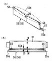
 tip portions 55b and 56b, and even if the tip portions 55b and 56b come into contact with the rotating pressure roller 31, the rotating shaft 55a The air conditioners 55 and 56 are easy to rotate around 56a and the outer peripheral surface of the pressure roller 31 is not easily damaged.

<変形例>
図7(A)は、変形例としての定着装置20における整風板55、56を示す斜視図であって、本実施の形態における図5に対応する図である。また、図7(B)は、その変形例としての定着装置20において、加圧ローラ31と整風板55、56とを幅方向に示す概略図であって、本実施の形態における図6(A)に対応する図である。なお、図7(B)は、図6(A)と同様に、整風板55、56の先端部55b、56bが加圧ローラ31に対向する位置を接線方向にみた図である。
図7(B)に示すように、変形例における加圧ローラ31(加圧回転体)は、回転軸方向に鼓状に形成されている。すなわち、加圧ローラ31は、その外径が、幅方向両端部から幅方向中央部にかけて漸減するように形成されている。本実施の形態では、加圧ローラ31の鼓み量N(最大外径部と最小外径部との半径差である。)が公知のものと同等に設定されている。
そして、この変形例においても、整風板55、56は、加圧ローラ31の外周面に対向する先端部55b、56bが、加圧ローラ31の外周面の形状に沿うように形成されている。詳しくは、変形例において、整風板55、56は、先端部55b、56bが、加圧ローラ31の鼓形状に合わせて回転軸方向(幅方向)にV字状に形成されている。具体的に、図7(A)、(B)に示すように、整風板55、56の先端部55b、56bは、鼓状に形成された加圧ローラ31に対して所望の隙間Gを幅方向にわたって形成するように、加圧ローラ31の鼓み量Nに合わせて、幅方向両端部に比べて幅方向中央部が距離Nだけ突出するようにV字状に形成されている。
このように構成した場合であっても、本実施の形態のものと同様の効果を得ることができる。
なお、この変形例では、整風板55、56の先端部55b、56bを、加圧ローラ31の鼓形状に合わせて回転軸方向にV字状に形成したが、図7(B)において破線で示すように、加圧ローラ31の鼓形状に合わせて回転軸方向にU字状に形成することもできる。
<Modification>
FIG. 7A is a perspective view showing the air conditioning plates 55 and 56 in the fixing device 20 as a modified example, and corresponds to FIG. 5 in the present embodiment. FIG. 7B is a schematic diagram showing the pressure roller 31 and the air conditioning plates 55 and 56 in the width direction in the fixing device 20 as a modified example thereof, and FIG. It is a figure corresponding to. FIG. 7B is a diagram in which the positions where the tip portions 55b and 56b of the air conditioning plates 55 and 56 are opposed to the pressure roller 31 are viewed in the tangential direction, as in FIG. 6A.
As shown in FIG. 7B, the pressure roller 31 (pressure rotator) in the modification is formed in a drum shape in the rotation axis direction. That is, the pressure roller 31 is formed so that the outer diameter gradually decreases from the both ends in the width direction to the center in the width direction. In the present embodiment, the drum amount N of the pressure roller 31 (the difference in radius between the maximum outer diameter portion and the minimum outer diameter portion) is set to be equal to a known one.
Also in this modified example, the air conditioning plates 55 and 56 are formed such that the end portions 55 b and 56 b facing the outer peripheral surface of the pressure roller 31 follow the shape of the outer peripheral surface of the pressure roller 31. Specifically, in the modified example, the air conditioning plates 55 and 56 have tip portions 55b and 56b formed in a V shape in the rotation axis direction (width direction) in accordance with the drum shape of the pressure roller 31. Specifically, as shown in FIGS. 7A and 7B, the tip portions 55b and 56b of the air conditioning plates 55 and 56 have a desired gap G with respect to the pressure roller 31 formed in a drum shape. It is formed in a V shape so that the central portion in the width direction protrudes by a distance N as compared to the both ends in the width direction in accordance with the drum amount N of the pressure roller 31 so as to be formed over the direction.
Even in this case, the same effect as that of the present embodiment can be obtained.
In this modification, the tip portions 55b and 56b of the air conditioning plates 55 and 56 are formed in a V shape in the direction of the rotation axis in accordance with the drum shape of the pressure roller 31. However, in FIG. As shown, it can also be formed in a U shape in the direction of the rotation axis in accordance with the drum shape of the pressure roller 31.

以上説明したように、本実施の形態における定着装置20は、加圧ローラ31(加圧回転体)の外周面に空気を当てて冷却する冷却機構50〜52や、加圧ローラ31の外周面に当てられる前の空気や外周面に当てられた後の空気が流れる方向や量を制限する整風板55、56が設けられている。そして、整風板55、56は、加圧ローラ31の外周面に対して隙間をあけて対向する先端部55b、56bが、加圧ローラ31の外周面の形状に沿うように形成されている。
これにより、加圧ローラ31の外周面に当てられた後の空気や、加圧ローラ31の外周面に当てられる前の空気が、意図せぬ方向に不均一に流れて、記録媒体Pの搬送性に影響してしまったり、空冷すべきでない他の部材を空冷してしまったり、加圧ローラ31をムラなく効率的に空冷できなかったりする不具合を生じにくくすることができる。
As described above, the fixing device 20 according to the present exemplary embodiment includes the cooling mechanisms 50 to 52 that cool air pressure by applying air to the outer peripheral surface of the pressure roller 31 (pressure rotating body), and the outer peripheral surface of the pressure roller 31. Air conditioning plates 55 and 56 are provided for restricting the direction and amount of air before being applied to the air and air after being applied to the outer peripheral surface. The air conditioning plates 55 and 56 are formed so that tip portions 55 b and 56 b facing the outer peripheral surface of the pressure roller 31 with a gap follow the shape of the outer peripheral surface of the pressure roller 31.
As a result, the air after being applied to the outer peripheral surface of the pressure roller 31 and the air before being applied to the outer peripheral surface of the pressure roller 31 flow unevenly in an unintended direction, and the recording medium P is conveyed. It is possible to make it difficult to cause problems that affect the performance, air-cool other members that should not be air-cooled, and that the pressure roller 31 cannot be air-cooled efficiently and uniformly.

なお、本実施の形態では加圧回転体として加圧ローラ31を用いたが、加圧回転体として加圧ベルトを用いてもよい。また、本実施の形態では定着回転体として定着ベルト21を用いたが、定着回転体として定着ローラを用いてもよい。
さらに、本実施の形態では定着回転体を加熱する加熱手段としてヒータ25を用いたが、定着回転体を加熱する加熱手段として励磁コイル(電磁誘導加熱方式の定着装置に対応する加熱手段である。)を用いることもできるし、加熱手段として抵抗発熱体を用いることもできる。
そして、それらのような場合にも、本実施の形態のものとほぼ同様の効果を得ることができる。
In the present embodiment, the pressure roller 31 is used as the pressure rotator, but a pressure belt may be used as the pressure rotator. In this embodiment, the fixing belt 21 is used as the fixing rotator, but a fixing roller may be used as the fixing rotator.
Further, in the present embodiment, the heater 25 is used as a heating unit for heating the fixing rotator. However, as a heating unit for heating the fixing rotator, an exciting coil (a heating unit corresponding to an electromagnetic induction heating type fixing device) is used. Or a resistance heating element can be used as a heating means.
In such cases, the same effects as those of the present embodiment can be obtained.

また、本実施の形態では、加圧ローラ31の外周面に当てられた後の空気が流れる方向や量を制限する整風板55と、加圧ローラ31の外周面に当てられる前の空気が流れる方向や量を制限する整風板56と、を設置して、その双方の整風板55、56に対して本発明を適用した。これに対して、これらの2つの整風板55、56のうち一方のみに本発明を適用することもできるし、2つの整風板55、56のうち一方のみを設置して本発明を適用することもできる。
そして、そのような場合にも、本実施の形態のものとほぼ同様の効果を得ることができる。
In the present embodiment, the air conditioning plate 55 that restricts the flow direction and amount of air after being applied to the outer peripheral surface of the pressure roller 31 and the air before being applied to the outer peripheral surface of the pressure roller 31 flow. An air conditioning plate 56 that restricts the direction and amount is installed, and the present invention is applied to both air conditioning plates 55 and 56. On the other hand, the present invention can be applied to only one of these two air conditioning plates 55 and 56, or only one of the two air conditioning plates 55 and 56 is installed to apply the present invention. You can also.
In such a case, substantially the same effect as that of the present embodiment can be obtained.

なお、本発明が本実施の形態に限定されず、本発明の技術思想の範囲内において、本実施の形態の中で示唆した以外にも、本実施の形態は適宜変更され得ることは明らかである。また、前記構成部材の数、位置、形状等は本実施の形態に限定されず、本発明を実施する上で好適な数、位置、形状等にすることができる。   It should be noted that the present invention is not limited to the present embodiment, and it is obvious that the present embodiment can be modified as appropriate within the scope of the technical idea of the present invention, other than suggested in the present embodiment. is there. In addition, the number, position, shape, and the like of the constituent members are not limited to the present embodiment, and the number, position, shape, and the like suitable for implementing the present invention can be achieved.

1 画像形成装置(画像形成装置本体)、
20 定着装置、
21 定着ベルト(定着回転体)、
22 定着補助ローラ、
23 加熱ローラ、
25 ヒータ(加熱手段)、
31 加圧ローラ(加圧回転体)、
40 温度センサ、
45、45A〜45C 温度センサ(温度検知手段)、
50 送風機(冷却機構)、
51、51A〜51C ダクト(冷却機構)、
52 排気ダクト(冷却機構)、
55、56 整風板(整風部材)、
55a、56a 回転軸、
55b、55b 先端部、
57 ねじりコイルスプリング、
58 突当部材、
59 仕切部材、 P 記録媒体。
1 image forming apparatus (image forming apparatus main body),
20 fixing device,
21 fixing belt (fixing rotating body),
22 fixing auxiliary roller,
23 Heating roller,
25 heater (heating means),
31 Pressure roller (pressure rotating body),
40 temperature sensor,
45, 45A-45C temperature sensor (temperature detection means),
50 blower (cooling mechanism),
51, 51A-51C Duct (cooling mechanism),
52 Exhaust duct (cooling mechanism),
55, 56 Air conditioning plate (air conditioning member),
55a, 56a rotation axis,
55b, 55b tip,
57 Torsion coil spring,
58 Abutting member,
59 Partition member, P recording medium.

特許第3566466号公報Japanese Patent No. 3565466

Claims (8)

トナー像を加熱して記録媒体上に定着する定着回転体と、
前記定着回転体に圧接することで記録媒体が搬送されるニップ部を形成する加圧回転体と、
前記加圧回転体の外周面に空気を当てて冷却する冷却機構と、
前記加圧回転体の外周面との間に隙間をあけて対向するように構成されて、前記加圧回転体の外周面に当てられる前の空気、又は、前記加圧回転体の外周面に当てられた後の空気、が流れる方向又は量を制限する整風板と、
を備え、
前記整風板は、前記加圧回転体の外周面に対向する先端部が、前記加圧回転体の外周面の形状に沿うように形成されたことを特徴とする定着装置。
A fixing rotator for heating and fixing the toner image on the recording medium;
A pressure rotator that forms a nip portion to which a recording medium is conveyed by being pressed against the fixing rotator; and
A cooling mechanism for cooling by applying air to the outer peripheral surface of the pressure rotating body;
It is configured to be opposed to the outer peripheral surface of the pressurizing rotator with a gap between the air before being applied to the outer peripheral surface of the pressurizing rotator, or the outer peripheral surface of the pressurizing rotator. An air conditioning plate that restricts the flow direction or amount of air after being applied, and
With
The fixing device according to claim 1, wherein the air conditioning plate is formed such that a tip portion facing the outer peripheral surface of the pressure rotator conforms to a shape of the outer peripheral surface of the pressure rotator.
前記整風板は、前記先端部が、前記加圧回転体の外周面の曲率に合わせて曲面状に形成されたことを特徴とする請求項1に記載の定着装置。   2. The fixing device according to claim 1, wherein the air conditioning plate has a front end portion formed in a curved shape in accordance with a curvature of an outer peripheral surface of the pressure rotating body. 前記加圧回転体は、回転軸方向に鼓状に形成されて、
前記整風板は、前記先端部が、前記加圧回転体の鼓形状に合わせて回転軸方向にU字状又はV字状に形成されたことを特徴とする請求項1又は請求項2に記載の定着装置。
The pressure rotator is formed in a drum shape in the rotation axis direction,
The said air conditioning board WHEREIN: The said front-end | tip part was formed in the U-shape or V-shape in the rotating shaft direction according to the drum shape of the said pressurization rotary body, The Claim 1 or Claim 2 characterized by the above-mentioned. Fixing device.
前記整風板は、前記先端部において非通紙領域に対応する幅方向両端部の位置にそれぞれ突当部材が設置されて、当該位置において前記突当部材を介して前記加圧回転体に当接するように構成されたことを特徴とする請求項1〜請求項3のいずれかに記載の定着装置。   The air conditioning plate is provided with abutting members at positions at both ends in the width direction corresponding to the non-sheet passing region at the tip, and abuts against the pressure rotator through the abutting member at the position. The fixing device according to claim 1, wherein the fixing device is configured as described above. 前記定着回転体に対して前記加圧回転体を接離方向に移動させる移動機構を備え、
前記整風板は、前記移動機構によって前記加圧回転体が接離方向に移動する動作に追従して前記加圧回転体の外周面に対して前記隙間と同等の隙間をあけて対向するように構成されたことを特徴とする請求項4に記載の定着装置。
A moving mechanism for moving the pressure rotator in the contact / separation direction with respect to the fixing rotator,
The air conditioning plate follows the movement of the pressing rotator in the contact / separation direction by the moving mechanism so as to face the outer peripheral surface of the pressing rotator with a gap equivalent to the gap. The fixing device according to claim 4, wherein the fixing device is configured.
前記整風板は、前記先端部に向けて前記加圧回転体との対向距離が漸減するように前記加圧回転体の外周面に対向して、前記先端部が前記加圧回転体の回転方向下流側に位置するように配設されたことを特徴とする請求項1〜請求項5のいずれかに記載の定着装置。   The air conditioning plate is opposed to the outer peripheral surface of the pressure rotator so that the distance to the pressure rotator gradually decreases toward the tip, and the tip is in the rotation direction of the pressure rotator. The fixing device according to claim 1, wherein the fixing device is disposed on a downstream side. 前記加圧回転体の表面温度を幅方向の複数箇所でそれぞれ検知する複数の温度検知手段を備え、
前記冷却機構は、前記複数の温度検知手段の検知結果に基づいて、前記加圧回転体の表面に対して前記複数の温度検知手段の設置位置に対応した幅方向の複数箇所にそれぞれ別々に空気を当てられるように構成されたことを特徴とする請求項1〜請求項6のいずれかに記載の定着装置。
A plurality of temperature detecting means for detecting the surface temperature of the pressure rotating body at a plurality of positions in the width direction, respectively;
The cooling mechanism is configured to separately air at a plurality of positions in the width direction corresponding to the installation positions of the plurality of temperature detecting units with respect to the surface of the pressurizing rotating body based on the detection results of the plurality of temperature detecting units. The fixing device according to any one of claims 1 to 6, wherein the fixing device is configured to be applied.
請求項1〜請求項7のいずれかに記載の定着装置を備えたことを特徴とする画像形成装置。   An image forming apparatus comprising the fixing device according to claim 1.
JP2015242833A 2015-12-14 2015-12-14 Fixing device and image forming apparatus Pending JP2017111162A (en)

Priority Applications (2)

Application Number Priority Date Filing Date Title
JP2015242833A JP2017111162A (en) 2015-12-14 2015-12-14 Fixing device and image forming apparatus
US15/369,592 US10078303B2 (en) 2015-12-14 2016-12-05 Fixing device and image forming apparatus including the fixing device

Applications Claiming Priority (1)

Application Number Priority Date Filing Date Title
JP2015242833A JP2017111162A (en) 2015-12-14 2015-12-14 Fixing device and image forming apparatus

Publications (1)

Publication Number Publication Date
JP2017111162A true JP2017111162A (en) 2017-06-22

Family

ID=59019683

Family Applications (1)

Application Number Title Priority Date Filing Date
JP2015242833A Pending JP2017111162A (en) 2015-12-14 2015-12-14 Fixing device and image forming apparatus

Country Status (2)

Country Link
US (1) US10078303B2 (en)
JP (1) JP2017111162A (en)

Cited By (1)

* Cited by examiner, † Cited by third party
Publication number Priority date Publication date Assignee Title
JP2020201347A (en) * 2019-06-07 2020-12-17 コニカミノルタ株式会社 Image forming apparatus

Families Citing this family (2)

* Cited by examiner, † Cited by third party
Publication number Priority date Publication date Assignee Title
JP7114389B2 (en) * 2018-07-31 2022-08-08 キヤノン株式会社 Fixing device
JP2023083049A (en) * 2021-12-03 2023-06-15 富士フイルムビジネスイノベーション株式会社 Fixation device

Family Cites Families (5)

* Cited by examiner, † Cited by third party
Publication number Priority date Publication date Assignee Title
JP3566466B2 (en) 1996-07-31 2004-09-15 株式会社リコー Fixing device
JP5581939B2 (en) 2010-03-15 2014-09-03 株式会社リコー Fixing device, image forming apparatus
JP5921096B2 (en) * 2011-06-22 2016-05-24 キヤノン株式会社 Image forming apparatus
JP2014137487A (en) 2013-01-17 2014-07-28 Ricoh Co Ltd Fixing device
JP2016006472A (en) 2014-03-12 2016-01-14 株式会社リコー Fixing device and image forming apparatus

Cited By (2)

* Cited by examiner, † Cited by third party
Publication number Priority date Publication date Assignee Title
JP2020201347A (en) * 2019-06-07 2020-12-17 コニカミノルタ株式会社 Image forming apparatus
JP7310331B2 (en) 2019-06-07 2023-07-19 コニカミノルタ株式会社 image forming device

Also Published As

Publication number Publication date
US10078303B2 (en) 2018-09-18
US20170168432A1 (en) 2017-06-15

Similar Documents

Publication Publication Date Title
JP6620936B2 (en) Fixing device, image forming apparatus
JP5424079B2 (en) Fixing apparatus and image forming apparatus
US7542692B2 (en) Image forming apparatus with detecting members for determining when set width is wrong
JP5891764B2 (en) Glossiness imparting apparatus and image forming apparatus
JP2008040437A (en) Transfer/fixing apparatus and image forming apparatus
JP2012098677A (en) Cooler and image forming device
JP6394873B2 (en) Fixing apparatus and image forming apparatus
JP6015176B2 (en) Glossiness imparting device and image forming apparatus
US10078303B2 (en) Fixing device and image forming apparatus including the fixing device
JP2016014774A (en) Fixing device and image forming apparatus
JP2015069041A (en) Fixing device and image forming device
JP2010044330A (en) Transfer fixing device and image forming apparatus
JP5765031B2 (en) Fixing apparatus and image forming apparatus
JP2010211080A (en) Fixing device, and image forming apparatus
JP2009015107A (en) Safety device, fixing device and image forming apparatus
JP2017015848A (en) Fixing device and image forming apparatus
JP2013238800A (en) Fixing device, and image forming apparatus
JP7161698B2 (en) Fixing device and image forming device
JP2015108799A (en) Fixing device, and image forming apparatus
JP6187116B2 (en) Fixing apparatus and image forming apparatus
JP2014228631A (en) Image forming apparatus
JP5332104B2 (en) Image forming apparatus
JP2014089233A (en) Fixing device and image forming apparatus
JP2013097175A (en) Gloss imparting device and image forming apparatus
JP7242244B2 (en) Fixing device and image forming apparatus having the same