JP5580934B2 - Method for manufacturing a dual biosensor test strip - Google Patents
Method for manufacturing a dual biosensor test strip Download PDFInfo
- Publication number
- JP5580934B2 JP5580934B2 JP2013518702A JP2013518702A JP5580934B2 JP 5580934 B2 JP5580934 B2 JP 5580934B2 JP 2013518702 A JP2013518702 A JP 2013518702A JP 2013518702 A JP2013518702 A JP 2013518702A JP 5580934 B2 JP5580934 B2 JP 5580934B2
- Authority
- JP
- Japan
- Prior art keywords
- test strip
- electrodes
- electrode
- layer
- manufacturing
- Prior art date
- Legal status (The legal status is an assumption and is not a legal conclusion. Google has not performed a legal analysis and makes no representation as to the accuracy of the status listed.)
- Expired - Fee Related
Links
Images


Classifications
-
- G—PHYSICS
- G01—MEASURING; TESTING
- G01N—INVESTIGATING OR ANALYSING MATERIALS BY DETERMINING THEIR CHEMICAL OR PHYSICAL PROPERTIES
- G01N27/00—Investigating or analysing materials by the use of electric, electrochemical, or magnetic means
- G01N27/26—Investigating or analysing materials by the use of electric, electrochemical, or magnetic means by investigating electrochemical variables; by using electrolysis or electrophoresis
- G01N27/28—Electrolytic cell components
- G01N27/30—Electrodes, e.g. test electrodes; Half-cells
- G01N27/327—Biochemical electrodes, e.g. electrical or mechanical details for in vitro measurements
-
- G—PHYSICS
- G01—MEASURING; TESTING
- G01N—INVESTIGATING OR ANALYSING MATERIALS BY DETERMINING THEIR CHEMICAL OR PHYSICAL PROPERTIES
- G01N27/00—Investigating or analysing materials by the use of electric, electrochemical, or magnetic means
- G01N27/26—Investigating or analysing materials by the use of electric, electrochemical, or magnetic means by investigating electrochemical variables; by using electrolysis or electrophoresis
- G01N27/28—Electrolytic cell components
- G01N27/30—Electrodes, e.g. test electrodes; Half-cells
-
- B—PERFORMING OPERATIONS; TRANSPORTING
- B01—PHYSICAL OR CHEMICAL PROCESSES OR APPARATUS IN GENERAL
- B01L—CHEMICAL OR PHYSICAL LABORATORY APPARATUS FOR GENERAL USE
- B01L3/00—Containers or dishes for laboratory use, e.g. laboratory glassware; Droppers
- B01L3/50—Containers for the purpose of retaining a material to be analysed, e.g. test tubes
- B01L3/502—Containers for the purpose of retaining a material to be analysed, e.g. test tubes with fluid transport, e.g. in multi-compartment structures
- B01L3/5027—Containers for the purpose of retaining a material to be analysed, e.g. test tubes with fluid transport, e.g. in multi-compartment structures by integrated microfluidic structures, i.e. dimensions of channels and chambers are such that surface tension forces are important, e.g. lab-on-a-chip
- B01L3/502707—Containers for the purpose of retaining a material to be analysed, e.g. test tubes with fluid transport, e.g. in multi-compartment structures by integrated microfluidic structures, i.e. dimensions of channels and chambers are such that surface tension forces are important, e.g. lab-on-a-chip characterised by the manufacture of the container or its components
-
- G—PHYSICS
- G01—MEASURING; TESTING
- G01N—INVESTIGATING OR ANALYSING MATERIALS BY DETERMINING THEIR CHEMICAL OR PHYSICAL PROPERTIES
- G01N27/00—Investigating or analysing materials by the use of electric, electrochemical, or magnetic means
- G01N27/26—Investigating or analysing materials by the use of electric, electrochemical, or magnetic means by investigating electrochemical variables; by using electrolysis or electrophoresis
- G01N27/28—Electrolytic cell components
- G01N27/30—Electrodes, e.g. test electrodes; Half-cells
- G01N27/327—Biochemical electrodes, e.g. electrical or mechanical details for in vitro measurements
- G01N27/3271—Amperometric enzyme electrodes for analytes in body fluids, e.g. glucose in blood
- G01N27/3272—Test elements therefor, i.e. disposable laminated substrates with electrodes, reagent and channels
-
- G—PHYSICS
- G01—MEASURING; TESTING
- G01N—INVESTIGATING OR ANALYSING MATERIALS BY DETERMINING THEIR CHEMICAL OR PHYSICAL PROPERTIES
- G01N33/00—Investigating or analysing materials by specific methods not covered by groups G01N1/00 - G01N31/00
- G01N33/48—Biological material, e.g. blood, urine; Haemocytometers
- G01N33/483—Physical analysis of biological material
- G01N33/487—Physical analysis of biological material of liquid biological material
-
- B—PERFORMING OPERATIONS; TRANSPORTING
- B01—PHYSICAL OR CHEMICAL PROCESSES OR APPARATUS IN GENERAL
- B01L—CHEMICAL OR PHYSICAL LABORATORY APPARATUS FOR GENERAL USE
- B01L2200/00—Solutions for specific problems relating to chemical or physical laboratory apparatus
- B01L2200/06—Fluid handling related problems
- B01L2200/0684—Venting, avoiding backpressure, avoid gas bubbles
-
- B—PERFORMING OPERATIONS; TRANSPORTING
- B01—PHYSICAL OR CHEMICAL PROCESSES OR APPARATUS IN GENERAL
- B01L—CHEMICAL OR PHYSICAL LABORATORY APPARATUS FOR GENERAL USE
- B01L2300/00—Additional constructional details
- B01L2300/06—Auxiliary integrated devices, integrated components
- B01L2300/0627—Sensor or part of a sensor is integrated
- B01L2300/0645—Electrodes
-
- B—PERFORMING OPERATIONS; TRANSPORTING
- B01—PHYSICAL OR CHEMICAL PROCESSES OR APPARATUS IN GENERAL
- B01L—CHEMICAL OR PHYSICAL LABORATORY APPARATUS FOR GENERAL USE
- B01L2300/00—Additional constructional details
- B01L2300/08—Geometry, shape and general structure
- B01L2300/0809—Geometry, shape and general structure rectangular shaped
- B01L2300/0825—Test strips
-
- B—PERFORMING OPERATIONS; TRANSPORTING
- B01—PHYSICAL OR CHEMICAL PROCESSES OR APPARATUS IN GENERAL
- B01L—CHEMICAL OR PHYSICAL LABORATORY APPARATUS FOR GENERAL USE
- B01L2400/00—Moving or stopping fluids
- B01L2400/04—Moving fluids with specific forces or mechanical means
- B01L2400/0403—Moving fluids with specific forces or mechanical means specific forces
- B01L2400/0406—Moving fluids with specific forces or mechanical means specific forces capillary forces
-
- Y—GENERAL TAGGING OF NEW TECHNOLOGICAL DEVELOPMENTS; GENERAL TAGGING OF CROSS-SECTIONAL TECHNOLOGIES SPANNING OVER SEVERAL SECTIONS OF THE IPC; TECHNICAL SUBJECTS COVERED BY FORMER USPC CROSS-REFERENCE ART COLLECTIONS [XRACs] AND DIGESTS
- Y10—TECHNICAL SUBJECTS COVERED BY FORMER USPC
- Y10T—TECHNICAL SUBJECTS COVERED BY FORMER US CLASSIFICATION
- Y10T156/00—Adhesive bonding and miscellaneous chemical manufacture
- Y10T156/10—Methods of surface bonding and/or assembly therefor
- Y10T156/1052—Methods of surface bonding and/or assembly therefor with cutting, punching, tearing or severing
- Y10T156/1084—Methods of surface bonding and/or assembly therefor with cutting, punching, tearing or severing of continuous or running length bonded web
Description
この出願は、2010年6月30日に提出された米国仮出願第61/360,010号の利益を主張する。 This application claims the benefit of US Provisional Application No. 61 / 360,010, filed June 30, 2010.
多くのヘルスケア分野において、血液や尿のような体液中に存在するある検体の繰り返しの測定およびモニタリングは特に重要である。1つの特殊なケースは、たとえば、的確な薬物治療で迅速に対応するために、非常に頻繁にグルコース濃度を測定する必要がある糖尿病にかかった患者に関する。ある血中グルコース限度を超えると、昏睡状態または死を引き起こす可能性がある。血中グルコースの緩やかな上昇でさえ、次第に健康を悪化させ、コントロール下で血中グルコースレベルを維持するために長期間のモニタリングが必要となる。このように、血中グルコースデータは、最も適切な長期治療を決定する役割がある医師、および、測定されたグルコースレベルに応じて、日々投薬の管理が必要な患者の双方にとって有益である。これらは、食生活だけでなく、日々の運動および代謝に影響する多くの他の要因にも依存する。 In many healthcare fields, the repeated measurement and monitoring of certain analytes present in body fluids such as blood and urine is particularly important. One special case involves, for example, patients with diabetes who need to measure glucose concentrations very frequently in order to respond quickly with the right medication. Exceeding certain blood glucose limits can cause coma or death. Even a gradual rise in blood glucose gradually deteriorates health and requires long-term monitoring to maintain blood glucose levels under control. Thus, blood glucose data is beneficial to both physicians who are responsible for determining the most appropriate long-term treatment, and patients who need to manage medication on a daily basis, depending on the measured glucose level. These depend not only on the diet, but also on many other factors that affect daily exercise and metabolism.
携帯可能な、小型で、信頼性があり、低コストの多くの医療機器は今日、セルフモニタリングをする患者にとって入手可能である。インスリンポンプのような、制御された治療薬の投薬用装置もまた市販されている。本発明で言及する例示的な医療機器の数は、しかしながら、糖尿病治療に限定されない。たとえば、血圧または凝固因子などの他の血液パラメータを監視する装置が、言及する価値があるものとしてあげられる。 Many portable, small, reliable and low cost medical devices are available today for self-monitoring patients. Controlled therapeutic drug dispensing devices, such as insulin pumps, are also commercially available. The number of exemplary medical devices referred to in the present invention, however, is not limited to diabetes treatment. For example, devices that monitor other blood parameters such as blood pressure or clotting factors are worth mentioning.
新規なテストストリップは、バイオセンサおよびその製造における改良の機会を提供する。一般的に期待されているように、テストストリップは、血中グルコースのような検体の存在または濃度について液体試料を検査することができるので、テストストリップは、糖尿病のような様々な疾患を監視するのに用いることができる。テストストリップは、液体試料を受け取る毛管チャンバとベントとを含んでいる。試料チャンバは、スペーサ層により離間された2つの基板層により、上部と下部とが境界付けられている。ユーザが毛管チャンバへの充填を視認できるように、基板のうちの少なくとも1つを透けているようにすること(透明または半透明)は任意である。水平方向では、毛管チャンバは、スペーサ層の切欠部と開口部により境界付けられている。いくつかの実施形態において切欠部は、迅速な試料充填のために最適化されたチャンバの幅に対するチャンバの深さであるアスペクト比を毛管チャンバに設けるように構成される。 The new test strip provides an opportunity for improvement in biosensors and their manufacture. As commonly expected, test strips can test liquid samples for the presence or concentration of analytes such as blood glucose, so test strips monitor various diseases such as diabetes Can be used. The test strip includes a capillary chamber for receiving a liquid sample and a vent. The sample chamber is bounded at the top and bottom by two substrate layers separated by a spacer layer. It is optional that at least one of the substrates is transparent (transparent or translucent) so that the user can see the filling of the capillary chamber. In the horizontal direction, the capillary chamber is bounded by a notch and an opening in the spacer layer. In some embodiments, the notch is configured to provide the capillary chamber with an aspect ratio that is the depth of the chamber to the width of the chamber optimized for rapid sample filling.
実施形態は、ユーザが容易かつ迅速に液体試料を投与できる幅の広い試料適用ポートを備えた、端部が略四角形状にされたテストストリップを含んでいる。テーパ状または湾曲した端部など、四角形状ではない実施形態も、同様の有利な投与の柔軟性を与える。ストリップに設けられた幅の広い投与位置は、視力が衰えた者、手の器用さが衰えた者、手を安定させるのが困難な者の助けとなり得る。実施形態では、少量の検査用液体しか要求されず、迅速に試料液体で満たされる試料チャンバも備えている。他の実施形態によりテストストリップを製造する場合、他の特徴は向上した製造効率およびコスト節約を含む。いくつかのまたは全てのこれらの特徴は、対応する独立請求項または従属請求項に示されるが、特定の請求項で明示的に示されない限り、限定解釈されるべきではない。 Embodiments include a test strip with a generally square end at a wide sample application port that allows a user to dispense liquid samples easily and quickly. Embodiments that are not square, such as tapered or curved ends, provide similar advantageous dosing flexibility. The wide dosing location on the strip can help those who have diminished vision, those who have weak dexterity, or those who have difficulty stabilizing their hands. Embodiments require a small amount of test liquid and also include a sample chamber that is quickly filled with sample liquid. When manufacturing test strips according to other embodiments, other features include improved manufacturing efficiency and cost savings. Some or all of these features are set forth in the corresponding independent or dependent claims but should not be construed as limiting unless explicitly indicated in the specific claims.
この概要は、本明細書に含まれる詳細な説明および図面においてさらに詳細に説明される概念の選択を紹介するために提供されている。この概要は、クレームされた特定事項の主要または本質的な特徴を特定する意図はなく、また、添付の請求項の範囲を決定する補助として使用されることを意図したものでもない。本明細書において記載されたそれぞれの実施形態は、本明細書において記載された全ての対象に向けられることを意図したものではなく、それぞれの実施形態は、記載されたそれぞれの特徴を含まない。本発明の他の形状、実施形態、目的、利点、効果、特徴および態様は、本明細書に含まれる詳細な説明および図面から当業者には明らかになるであろう。 This summary is provided to introduce a selection of concepts that are further described in detail in the detailed description and drawings contained herein. This summary is not intended to identify key features or essential features of the claimed subject matter, nor is it intended to be used as an aid in determining the scope of the appended claims. Each embodiment described herein is not intended to be addressed to all objects described herein, and each embodiment does not include each described feature. Other shapes, embodiments, objects, advantages, effects, features and aspects of the present invention will become apparent to those skilled in the art from the detailed description and drawings contained herein.
本発明の原理の理解を促進する目的で、図面に示された選択された実施形態を参照し、それを説明するために特定の用語を使用する。しかし、それにより本発明の範囲が限定されることを意図するものではなく、本発明の原理のそのような変更、修正およびさらなる適用は、本発明に関連する技術分野における当業者に自然に想起し得るものとして考えられることが理解される。いくつかの特徴またはいくつかの特徴の組み合わせは、明瞭にする目的で示されていないことは関連する技術分野における当業者には明らかであるが、本発明の少なくとも1つの実施形態がより詳細に示されている。 For the purpose of promoting an understanding of the principles of the invention, reference will be made to selected embodiments illustrated in the drawings and specific language will be used to describe the same. However, it is not intended that the scope of the invention be limited thereby, and such changes, modifications and further applications of the principles of the invention will naturally occur to those skilled in the art to which the invention pertains. It is understood that it can be considered as possible. It will be apparent to one skilled in the relevant art that some features or combinations of features are not shown for purposes of clarity, but at least one embodiment of the present invention will be described in greater detail. It is shown.
図1に示されるのは1つの実施形態による、たとえばテストストリップ100であるバイオセンサである。テストストリップ100は、一般的には、長手軸102を画定する、平坦な、細長い矩形状である。テストストリップ100は、電極および接続パッドパターン106を有する検査器接続端部104を含み、検査器接続端部104は体液中の試料内の検体の濃度および/または存在を判定する検査器に接続される。テストストリップ100は、さらに流体サンプリング端部108を含み、検査用の体液の試料を収集する。
Shown in FIG. 1 is a biosensor, for example a
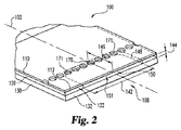
図2に移り、テストストリップ100はさらに、上部基板層110、中間基板層(たとえば、スペーサ120)および下部基板層130を含んでいる。スペーサ120は、垂直方向で上部基板層110と下部基板層130の間に位置している。サンプリング端部108は、上部基板層110の上部基板前縁部112を含んでいる。スペーサ120は、後述するようにサンプリング端部108へ伸びるスペーサ前縁部122を含んでいる。同様に、サンプリング端部108は、下部基板層130の下部基板前縁部132を含んでいる。
Turning to FIG. 2,
「上部」および「下部」という用語(および「頂部」「底部」のような同様の用語)は、本明細書に開示された実施形態の範囲を狭めることなく、図示された実施形態の記載を容易に読むことおよび理解することを目的として、「第1」および「第2」のような専門用語の代わりに図示目的で使用されている。方向的な優先を意図したものでもない。たとえば、「第1」、「第2」および「下部」は、「上部」および「第2」の代わりに代替的に使用することができ、「第1」および「上部」は(それぞれ)、「下部」の代わりに代替的に使用することができる。実施形態は、「上部」層が「底部」層になるように、「底部」層が「上部」層になるように反転させることもできることが理解される。 The terms “top” and “bottom” (and similar terms such as “top” and “bottom”) are used to describe the illustrated embodiments without narrowing the scope of the embodiments disclosed herein. For ease of reading and understanding, terminology is used for illustration purposes instead of terminology such as “first” and “second”. It is not intended for directional priority. For example, “first”, “second” and “bottom” can be used instead of “top” and “second”, where “first” and “top” are (respectively), It can alternatively be used instead of “bottom”. It is understood that embodiments can be inverted so that the “bottom” layer becomes the “top” layer, so that the “top” layer becomes the “bottom” layer.
「前」という用語も、本明細書に開示された実施形態の範囲を狭めることなく、図示された実施形態の記載を容易に読むことおよび理解することを目的として、使用されている。方向的な優先を意図したものでもない。たとえば、「縁部」という用語単独は、「前縁部」の代わりに代替的に使用することができる。実施形態は、「前」が「後」になるように回転させてもよいことが理解される。 The term “previous” is also used for the purpose of easily reading and understanding the description of the illustrated embodiments without narrowing the scope of the embodiments disclosed herein. It is not intended for directional priority. For example, the term “edge” alone can alternatively be used instead of “front edge”. It is understood that the embodiments may be rotated so that “front” is “back”.
スペーサ120は、第1切欠部148を含んでいる。テストストリップ100が組み立てられたとき、第1切欠部148は試料チャンバ150を画定する。試料チャンバ150は検査用の液体試料を受け入れることができる大きさにされている。試料チャンバ150は、上部基板層110と下部基板層130の間の切欠部148により設けられた空間内に形成される。上部基板層110の部分は、試料チャンバ150の上部側の境界を形成し、下部基板層130の部分は、試料チャンバ150の下部側の境界を形成する。試料チャンバ150は、サンプリング端部108において開口部151を有している。試料チャンバ150の寸法は、高さ144、幅142、奥行き146を有している。図示された実施形態では、第1切欠部148の領域は、以下に詳細に説明するように、下部基板層130およびその上の電極の部分を露出している。図示された実施形態では、上部基板層110は、試料チャンバ150に対して並んだベント開口部170を含んでいる。代わりに他の実施形態では、下部基板層130がベント孔を含んでいる。さらに、試料チャンバ150用のベント開口部は、任意の適切な方法により設けられる。いくつかの実施例は、本明細書で記載されるように、試料チャンバ150と並んだ孔を含むことができ、または、米国特許第7,829,023号に開示されているようなスロット状のベント配列によってもよく、この開示は参照により本明細書に引用される。
The
さらに他の実施形態では、ベント開口部170は、頂部基板110に直線状に離間した複数の孔171を備えている。孔171は、カバーに横断状の配置で、切欠部148上へのベントの位置合わせを容易にするために試料チャンバの幅142よりも小さい最大距離だけ離間して設けてもよい。結果として、少なくとも1つの孔171が常に切欠部148の上に位置するので、ベント開口部170の位置合わせは、概して長手方向の寸法だけが要求され、製造の問題としては、試料チャンバの奥行きに対する所望の位置への配列だけが残る。
In yet another embodiment, the
図3を参照すると、テストストリップ100はさらに、検査中に液体試料と反応する試薬、たとえば試薬層152を含んでいる。図示された実施形態では、試薬層152は、サンプリング端部108に形成された電極パターン155を覆い、接触している。電極パターン155は、試料チャンバ150内に形成され、通常検査中に試料液体に直接接触する。電極パターン155は、テストストリップ100の検査器接続端部104の接触パッドパターン106に、電極トレース156により電気的に接続されている。接着層158が下部基板層130とスペーサ120との間に位置し、下部基板層130とスペーサ120とを固着する。第2接着層158´は、上部基板層110とスペーサ120との間に位置し、上部基板層110とスペーサ120とを固着する。スペーサ120と、第1および第2接着層158、158´とは、試料チャンバ150の所望の高さ144を画定するのに充分な結合された厚さを有する。さらに、第1および第2接着層158、158´は、そこから取り除かれた、第1切欠部148と同様の大きさの第2切欠部159、159´を有している。1つの他の実施形態では、分離した接着層158、158´が必要ないように、スペーサ120は、感圧接着剤(またはPSA)のような両面接着層を備えている。この実施形態では、両面テープのような両面接着層が、試料チャンバ150の所望の高さ144を画定するのに充分な厚さを有している。
Referring to FIG. 3,
使用できる接着剤の例には、感圧接着剤、ホットメルトおよび他のヒートシール可能な接着剤、コールドシール可能な接着剤が含まれる。さらに他の実施形態では、接着フィルムまたは層を使用するよりも、一般的にこの技術分野において知られた方法により、ヒートシールやレーザーシールによりバイオセンサの層が固着される。 Examples of adhesives that can be used include pressure sensitive adhesives, hot melt and other heat sealable adhesives, cold sealable adhesives. In yet another embodiment, the biosensor layer is secured by heat sealing or laser sealing, generally by methods known in the art, rather than using an adhesive film or layer.
図3に示されているのは、電極パターン155の一実施形態である。電極パターン155の構造は以下において詳細に説明する。電極パターン155は、この技術分野において周知の適切な方法により試料チャンバ150内に作られる。電極パターン155は、たとえば広範囲レーザーアブレーション技術または他の高精細度、高精度品質の電極パターン形成方法を使用して製造することができ、それは現在のインクジェット技術の技術水準で達成することができる。
Shown in FIG. 3 is one embodiment of an
1つの実施形態において、広範囲レーザーアブレーションは、リールツーリール構造内で使用され、それぞれのレーザーパルスで多数の電極パターン155を形成する。すなわち、2つまたは3つ以上の隣接するパターンは、金属被覆された基板のウェブがレーザーアブレーションチャンバを通って巻き取られたときに、単一のレーザーパルスにより形成され得る。単一のパルスで多数のパターンを形成することにより、全体の製造プロセスにおける電極製造工程のスループットが向上する。これは、典型的には多数の電極パターンを含む(すなわち、シングルパターンマスクよりも大きい)適切なレーザーマスクと、マスクを通してレーザーを方向付けるレンズであって、より大きなマスクを通してもレーザーが充分に方向付けられる、レーザーのより広い分散を提供するレンズとを設けることにより、公知の広範囲レーザーアブレーション技術を使用して達成することができる。この単一のパルスを使用する多数のパターン形成は、以下においてさらに説明する2アップ製造プロセスにおいても利点を与える。
In one embodiment, extensive laser ablation is used in a reel-to-reel structure to form
使用において、テストストリップ100の検査器接続端部は、図4に示された検査器165に挿入される。検査器165は、ユーザに情報および/または指示を与えるディスプレイ166を含んでいる。試料流体、たとえば血液または間質液試料は、典型的にはランセットまたは針のような鋭い物体で皮膚表面を穿刺することにより得られる。試料流体が、創傷から出てくると、皮膚の表面上に集まり、ユーザは試料流体の液滴を試料チャンバ150の開口部151に接触させる。流体が試料チャンバ150の開口部に接触するとき、試料チャンバ150は毛管作用により液体を内側へ引き込む。
In use, the tester connection end of the
図5に図示された実施形態に示されるように、充分な量の試料が投与されたことを判定するために、2つの試料充足電極164が、試料チャンバ150内に設けられてよく、そのような目的のために、これらの電極164を作動させる周知の方法が使用される。試料チャンバ150内での充足電極164の配置および作動により、試料流体が完全に作用電極を覆うまで、(テストストリップが検査器に挿入された時点で)検査が開始されないことを保証するのに役に立つ。すなわち、分析を開始することができるようになる前に、試料流体が試料充足電極の間のギャップを埋める必要があり、流体によりそのように埋められたことを電気的に検出する公知の方法を使用する。チャンバ150の構造、予想される充填の流れパターン(たとえば図5参照)、電極パターン155の構造に基づいて試料チャンバ150内に試料充足電極164を最適に位置付けることは、充分にこの分野の通常の技術の範囲内である。大前提としては、電極パターン155も試料流体によって少なくとも正確な測定を行うのに必要な程度覆われるまで、試料充足電極が試料流体によってつながれないことを保証することである。したがって、毛管前面の単一の流れの中で、電極164は、完全に電極パターン155の下流に位置する。しかし、図5に図示したような毛管前面の多数の流れの中では、試料チャンバ150の側縁において離間するような配置で置くことができ、これにより電極164の間に配置された電極パターン155が試料流体により充分に覆われることを保証する。
As shown in the embodiment illustrated in FIG. 5, two
図5は、試料が試料チャンバ150を満たすときの、開口部148における試料チャンバ150に入ってくる試料流体の一般的な広がり方を示している。示された例では、試料流体は、試料チャンバの幅のほぼ中央において入って、概して内部に移動した後、方向168に沿って概して外側に移動して略T字状に広がっている。試料がベント開口部170、171周辺まで試料チャンバ150の奥行きを満たすと、試料はテストストリップ100の長手軸102にほぼ垂直な方向に流れる。2つの方向を同時に満たすことにより、試料チャンバ150は、1つだけの方向で満たす同様の大きさの試料チャンバよりも早く満たすことができる。
FIG. 5 shows the general spread of the sample fluid entering the
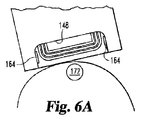
図6A〜6Dは、別の表示であるが、二次元における流体試料による試料チャンバ150の満たし方を示している。図6Aは試料チャンバ150に接触する前の試料流体の液滴を示している。図6Bは、試料チャンバ150内へ内側に広がる試料流体172の液滴を示し、そこで試料流体172の液滴が切欠部148の下流側縁部に隣接した位置に到着し始めている。図6Cは、2つの外側の方向へ、切欠部148の下流側縁部に沿って広がる液滴172を示している。図6Dは、試料充足電極164に接触し、試料チャンバ150を満たし続けている液滴172を示している。
6A-6D are alternative representations, showing how the
本発明の実施形態は、改善された試料収集特性を示している。たとえば、開示された発明の実施形態を検査するとき、予期できない迅速な充填時間が実現された。迅速な充填時間は、試料流体を検査するユーザにより必要とされる時間量を減らす。迅速な充填時間は、蒸発を少なくし、たとえば、ユーザから搾り出される必要のある血液の合計量を減らす。試料の量がより少量であることにより、血管が多い検査箇所ではないが痛みの少ない別の検査箇所からの血液を得ることが可能になる。いくつかの実施形態において、上部基板層110の下面(試料チャンバ150と面する面)は、親水性材料からなり、これはさらに試料チャンバ150が迅速に流体を満たす能力を向上させることができる。他の実施形態では、試料チャンバ150の底部が親水性の試薬層152で被覆され、それにより試料チャンバが迅速に流体を満たす能力を向上させることができる。
Embodiments of the present invention show improved sample collection characteristics. For example, when testing embodiments of the disclosed invention, an unexpected and quick fill time was achieved. Fast fill time reduces the amount of time required by the user examining the sample fluid. A quick filling time reduces evaporation and, for example, reduces the total amount of blood that needs to be squeezed out by the user. When the amount of the sample is smaller, it is possible to obtain blood from another examination site with less pain but not an examination site with many blood vessels. In some embodiments, the lower surface of the upper substrate layer 110 (the surface facing the sample chamber 150) is made of a hydrophilic material, which can further improve the ability of the
試料チャンバ150のアスペクト比(この比は、試料チャンバの幅142で試料チャンバの奥行き146を割ったものと等しい)が、試料チャンバ150の充填時間に影響を与えることが発見された。一般に、より小さなアスペクト比は、より大きなアスペクト比よりも充填時間がより速くなる。アスペクト比が1.0よりも小さい試料チャンバは、二次元の充填(たとえば、図5〜6D参照)が可能であり、試料チャンバを満たすのに必要なトータルの時間が減った。試料流体が、試料チャンバ150の幅に沿って横方向に広がる前に、切欠部148の下流側端部に接触する二次元充填を達成するためには、試料チャンバの奥行き146を試料チャンバの幅142よりも小さくすることが望ましい。言い換えると、1.0より小さいアスペクト比により、試料チャンバ150の迅速な充填時間が得られる。1.0より大きいアスペクト比は、試料チャンバ150の不完全な充填をもたらし、電極パターン155上の空気のトラップを引き起こし、検査エラーをもたらす可能性がある。一実施形態において、試料チャンバ150は、たとえば、試料チャンバの奥行き146が1mmで試料チャンバの幅145が5mmのアスペクト比0.2を有している。他の実施形態では、試料チャンバ150のアスペクト比は、少なくとも1/9(約0.1)、最大1/3(約0.3)である。別の実施形態では、アスペクト比は、少なくとも1/6(約0.17)、最大1/4(約0.25)である。
It has been discovered that the aspect ratio of the sample chamber 150 (which is equal to the
アスペクト比に加えて、試料チャンバの全体の寸法(大きさ)は、試料チャンバがどの程度迅速に充填されるかに影響を与える。一般に、大きな試料チャンバよりも小さな試料チャンバを満たすには、より少ない流体が必要であり、小さな試料チャンバを満たす時間は、大きな試料チャンバよりも短くなるべきであることを示している。しかし、試料チャンバの高さ144が所定よりも小さい寸法では、充填時間が長くなることが発見された。たとえば、全血を収集するとき、試料チャンバの高さ144が100μmより低くなるにつれて、試料チャンバ150の充填時間が長くなる。
In addition to the aspect ratio, the overall dimension (size) of the sample chamber affects how quickly the sample chamber is filled. In general, filling a smaller sample chamber than a larger sample chamber requires less fluid, indicating that the time to fill a smaller sample chamber should be shorter than a larger sample chamber. However, it has been discovered that the fill time is longer for
たとえば65〜85%の基準のヘマトクリット値よりも高い試料流体を投与するとき、試料チャンバ150の充填時間が速くなるであろうことが期待される。血清、血漿、または水溶液を採取し検査するのに適した試料チャンバは、より低い試料チャンバ高さを用いることができ、より速い充填時間を達成することが可能である。
For example, it is expected that the fill time of the
図5〜6Dは、試料チャンバの中央に適用される試料流体の液滴を示しているが、より広い前面開口部151の幅に沿ういずれの場所に液滴を適用してもよいことが理解されるべきである。より広い前面開口部151の幅に沿ういずれの場所にも試料を置くことができることは、全てのユーザ、特に糖尿病患者には珍しくない視力が衰えたユーザにとって利点である。なぜなら、視力が衰えた人は、テストストリップの幅に沿った正確な位置に試料を置くことができないからである。このように、テストストリップ100の幅142が、障害のあるユーザが容易にテストストリップ100を使用できるのに充分に大きい場合に利点が実現される。一実施形態において、試料チャンバ150の幅142は少なくとも3mm、最大9mmである。他の実施形態においては、試料チャンバ150の幅142は少なくとも4mm、最大6mmである。さらに他の実施形態においては、試料チャンバ150の幅142は5mmである。
5-6D show a sample fluid droplet applied to the center of the sample chamber, it will be appreciated that the droplet may be applied anywhere along the width of the wider
二次元的に充填する試料チャンバ150の能力は、迅速に充填する試料チャンバ150の能力を向上させる一方、試料チャンバ150の大きさが相対的に小さい場合は、さらにその迅速な充填能力を向上させ、検査に必要な試料流体の量を最小限にする。たとえば、検査に必要な流体が多いほど、試料チャンバ内への同一または類似した流体の流速の場合には試料チャンバを満たすのに多くの時間が必要となる。しかし、非常に少ない試料の量は、蒸発のために、検査の間に試料量が相対的に大きく変化し、検査結果に不利な影響を与える可能性がある。これらと他の要因をバランスするうえで、他の実施形態では、最大1000nl、最大500nl、最大100nlの試料チャンバ容量を有している。
The ability of the
所定の試料チャンバの幅142では、より長い試料チャンバの奥行き146は容量を増大させ、アスペクト比を増大させ、試料チャンバ150の試料チャンバ充填時間を増大させる。しかし、非常に短い試料チャンバの奥行き146は、製造プロセスの間、不利な影響を与える可能性がある。たとえば、以下に図7に関連して記載された方法を用いてテストストリップを製造する場合、頭を向き合わせた(head-to-head)テストストリップを分離するときの小さなエラーが、試料チャンバの奥行きが短い場合には、試料チャンバ容量に大きな変化をもたらしてしまう。実施形態は、最大1.5mmに等しい試料チャンバの奥行き146を有している。他の実施形態では、最大1.0mmに等しい試料チャンバの奥行き146を有している。
For a given
一実施形態において、試料チャンバ150が流体で満たされる間に視覚的なフィードバックをユーザに与えるために、少なくとも上部基板層110は試料チャンバ150の領域が透明である。透明な上部基板層110を通じて視認することにより、試料チャンバ150が流体で満たされたことがユーザによって確認されると、検査中の試料チャンバ内での流体の動揺を避けるために、ユーザは試料チャンバ150から試料流体の供給を止めることができ、検査結果に不利な影響を与える可能性がある。
In one embodiment, at least the
電極パターン155は典型的には1つの基板層上、下部基板層130上に形成される。しかしながら、他の実施形態は、組み立てられたテストストリップにおいて互いに向かい合った2つの基板表面に形成される、対向した(または、向かい合ったと呼ぶ)試料端部電極パターンを含んでいる。この配置は、さらにテストストリップの幅を減らすのに役立つ。しかし、テストストリップが非常に狭い場合、ユーザ、特に障害のあるユーザが扱うのが困難になる可能性がある。
The
単一の基板上に電極パターンを形成することは、テストストリップの性能や検査結果に不利な影響を与え得る電極の分離にあたっての変化を減らすことに役立つ。向かい合う電極(2つの向かい合う基板層上に形成され、互いに向かい合う電極)間の分離距離は、スペーサ120または接着層158、158´の厚さの変化により生じる試料チャンバの高さ変化など、試料チャンバの高さの変化とともに変わる。しかし、試料チャンバの高さの変化は、同じ基板上に形成された電極間での分離には影響しない。この特徴は、使用前にロットに関連するコード(一般的には所定の修正要因)の入力をすることなく使用する目的のテストストリップを製造する場合に特に有利である。必要または要求される電極の形状、大きさまたはスペースを調整する、1つまたは2つ以上の単純な変更を電極パターン設計に加えることができるので、製造の間に、同一平面上の電極(同じ基板層上に形成されたときのような、同じ平面上に位置する電極)のさらなる利点を実現することができる。
Forming an electrode pattern on a single substrate helps to reduce changes in electrode separation that can adversely affect test strip performance and test results. The separation distance between the facing electrodes (electrodes formed on two facing substrate layers and facing each other) is the height of the sample chamber, such as a change in the height of the sample chamber caused by a change in the thickness of the
さらに、他の実施形態において、単一の基板(たとえば、下部基板層130)上に電極パターン155を含むことにより、他の基板層(たとえば、上部基板層110)の一部または全てを透明または半透明にすることができ、ユーザがはっきりと試料の位置を識別すること、試料チャンバが適切に満たされているかおよび/または満たされたかを視認することに役立つ。既に満たされた試料チャンバに充填しようと試みることは、試料を動揺させる可能性があり、検査結果に不利な影響を与えるので、流体により満たされた試料チャンバの視覚的なフィードバックが得られることは、満たされた試料チャンバへの充填を止めるのを知るのに役立つ。
Furthermore, in other embodiments, including an
他の実施形態では、半透明の層110は、バイオセンサの接触端部に隣接した位置にある光源から、たとえば、検査器のストリップポートからの照明を伝えるライトガイドまたはライトパイプとして使用することができる。この照明は、ユーザが、光が少ない状況において、ストリップの投与領域148を見えるようにすることができる。この光は、縁部112に沿って放射され、適用される試料を見えるようにする照明を提供することができる。
In other embodiments, the
さらに、当業者に一般的にカバー、リッドまたはルーフとも呼ばれる、透明または半透明な上部基板層の利点は、クリスモア(Crismore)の米国特許第5,997,817号で説明されており、この開示は参照により本明細書に引用される。 Further, the advantages of a transparent or translucent top substrate layer, commonly referred to by those skilled in the art as a cover, lid, or roof, are described in Crismore US Pat. No. 5,997,817, the disclosure of which Are hereby incorporated by reference.
図2を参照すると、上部基板前縁部112、スペーサ前縁部122および下部基板前縁部132は、概して揃っている。特にたとえば以下に図7に関して説明するような2アップ製造プロセスを使用したときに、縁部112、122および132をこのように揃えることにより、良い製造効率が実現できる。なぜなら、単一化プロセスの間にテストストリップが互いから分離されるとき、一度の垂直方向の切断が、上部基板層110、スペーサ120および下部基板層130を経て行われるからである。
Referring to FIG. 2, the upper
図7は、テストストリップが頭を向き合わせた配置で製造された別の製造技術、別の言い方では「2アップ」製造技術を示している。2アップ製造プロセスを用いて、複数の電極パターン301が、下部基板330の伸長した層(テープ)上の2つの列(列Aの1つの電極パターンのセット、列Bのもう1つのセット)に配置されている。それぞれの列の電極パターンは、隣り合うように配置され、本開示を考慮して当業者に理解されるように、必要ではないが、1つの列の個々のパターンが、概ね他の列の個々のパターンとは逆になることが一般的に有益である。
FIG. 7 shows another manufacturing technique in which the test strip is manufactured in a head-to-head arrangement, in other words a “two-up” manufacturing technique. Using a two-up manufacturing process, a plurality of
試料チャンバ電極パターン355は互いに近接して位置し、下部基板ストリップ330の中央部近傍に位置し、コンタクトパッド306は互いから離間し、下部基板ストリップの向かい合う縁部の近傍に位置している。図示された実施形態では、電極パターンは全て同様であり、しかしながら、別の実施形態では、少なくともいくつかの電極パターンは、他の電極パターンとは異なっている。
The sample
試薬352の層は、好ましくは2つの電極パターン355を同時に覆ってストライプ状に塗布され、たとえば2〜10μmの厚さになるまで乾燥される。試薬層352は、真空補助を用いた改良されたスロットダイコーターのような高速コーティングプロセスを用いて塗布することができ、または、たとえばブレードコーティング、ディスペンシング、インクジェットコーティング、スクリーン印刷、回転スクリーン印刷を用いて塗布することができる。試薬層352のより個別な配置を有する例示的な他の実施形態が図8に示されている。
The layer of
2アップ製造技術を用いることにより、下部基板テープ330の同じ長さ(テストストリップの長手軸102(図1参照)に垂直な方向で測ったとき)で、並んで向いた複数の電極パターンを有する単一の列のものに比べて、2倍の数のテストストリップが製造され、コストを低減し、無駄を減らし、アウトプットを増加させるのに役立つ。
By using a two-up manufacturing technique, it has a plurality of electrode patterns oriented side by side at the same length of the lower substrate tape 330 (measured in a direction perpendicular to the
1つの伸長したストリップ(テープ)は、スペーサ層320を形成し、電極パターンの両方の列を覆う。スペーサ層320は、試薬352を適用する前または後のいずれかに、下部基板層330の上部に取り付けられる。代わりに、2つの伸長したストリップ(テープ)は2つのスペーサ層を形成し、スペーサ材料の2つの分離したストリップは個々に下部基板層330に取り付けられ、1つは列A用で、もう1つは列B用である。この実施形態(図示せず)では、両方のスペーサ層の前縁部は、中心線331に沿って揃えることができる。
One elongated strip (tape) forms the
スペーサ320は中心線331に沿って配置された複数の切欠部348を含んでいる。スペーサ320の切欠部348は、様々な技術により形成することができる。切欠部348を形成する技術の1つは、ダイカッティングを含む。スペーサ320が下部基板層330に取り付けられたとき、切欠部348は試料チャンバの周縁を形成する。
The
上部基板層310は、スペーサ層320の上部に取り付けられる。上部基板層310は、単一の連続した層である。図示された実施形態では、下部基板330、スペーサ層320および上部基板310は、接着層358、358´により取り付けられる。この接着層は、PSA、接着テープ、スプレーされた接着ストライプ、ホットメルト、共押出、またはヒートシール層の伸長したストリップであってよい。図示された実施形態では、接着層358、358´は、中心線331に沿って配置された複数の切欠部359、359´を含み、切欠部348に対応している。切欠部359、359´は、切欠部348と同様の大きさにされる。代わりに、頂部接着層358は、開口部も切欠部もない固体の層とすることができる。さらに、スペーサ320と頂部接着層358との間に親水性コーティングを設けて、接着層358と試薬352の間の直接的な接触を防止する。この親水性コーティングは、親水性が試料チャンバの内側面に与えられるように選択され、血液のような水分を含んだ試料の試料チャンバへの流れを促す。代わりに、スペーサ層320は、両面接着テープとすることができ、分離した接着層358、358´の必要性を取り除く。接着層を使わない別のバイオセンサの層の固定方法は、ヒートシール、レーザーシール、コールドシール等を含む。
The
下部基板330、試薬352、スペーサ層320および上部基板310が組み合わされてともに積層された後、シートまたはロールは個別のテストストリップに分離される。列Aのテストストリップは、典型的には中心線に沿って単一の切断を用いて、列Bのテストストリップから分離され(頭を向かい合わせて向いたテストストリップの試料チャンバは、ほぼ中心線331に沿って互いから分離される)、隣接した行のテストストリップ(並んで向いたテストストリップ)は、電極パターンの間で互いから分離される。図11〜12に関して以下に説明される他の実施形態は、複数の切断を用いている。
After the
上で説明したように、広範囲レーザーアブレーション技術が電極パターン355を形成するのに用いられるとき、それぞれのレーザーパルスから多数のパターンを形成するようにアブレーション技術を構成することができる。2アップ製造プロセスにおいて、多数のパターンは、列AとBとが向き合うパターンとすることができ、レーザーレンズが充分に大きい場合(そして適切なマスクが設けられる場合)、多数のパターンは、特定の列内で横方向に隣接するパターンおよび列の間で向かい合って隣接するパターンを含むことができる。一実施形態において、単一のパルスで4つのパターンが形成される。他の実施形態では、単一のパルスで6つ以上のパターンが形成される。上述したスループットの利点に加えて、単一のアブレーションパルスで列AとBの間で互いに向かい合う電極パターンを形成できることによって、列の間の間隔の変化を最小に保つことにも寄与する。これはスペーサ120の配置を位置付け、制御するために電極パターンを使用することにより、毛管の幅146に見られる変化を制御することに役立つ。電極パターンの正確な間隔は、ストリップ内の他の構成要素を位置付け、配置する基準点として使用することができる。
As explained above, when extensive laser ablation techniques are used to form the
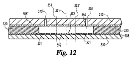
図9に示されるのは、図7に示された層を互いに取り付けた後の、頭が向かい合ったテストストリップの対302の断面図である。上部基板310は接着層358´に取り付けられ、接着層358´はスペーサ層320に取り付けられ、スペーサ層320はもう1つの接着層358に取り付けられ、接着層358は下部基板層330に取り付けられる。電極パターン301および試薬層352は下部基板330の上部に位置している。試料チャンバ350は、上部基板層310、接着層358、358´、スペーサ層320および下部基板層330の間の空間で、垂直方向に画定される。試料チャンバ350の周縁は、スペーサ層320の切欠部348により画定され、2つの試料チャンバ350を形成するために中心線331により切欠部348を分割する。
Shown in FIG. 9 is a cross-sectional view of a pair of
図10に示されるのは、他の実施形態による上部基板310Aを有する、頭が向かい合ったテストストリップの対304である。上部基板310Aの使用により、図9に示されたスペーサ層320を不要にする。上部基板310Aは、たとえば溝314のような凹部を含み、下部基板層330および接着層358とともに試料チャンバ350を画定する。試料チャンバ350は中心線331により分割される。溝314の深さおよび幅は、製造プロセスの間に正確に制御される。このように、試料チャンバ350の大きさは正確に制御され、スペーサ層320を含めること、揃えること、取り付けることについての必要性が無くなる。一実施形態では、溝314はレーザーアブレーションにより形成される。他の実施形態において、溝314はカレンダ加工プロセスを使用して形成され、完成したテストストリップが効率的な積み重ねのためのフラットな外形を維持することができる。さらに別の実施形態では、溝314はスカイビング加工によりまたはエンボス加工により形成される。
Shown in FIG. 10 is a pair of head-to-
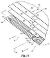
図11および12に示されるのは、頭を向かい合わせた配置のテストストリップを製造する他の実施形態の製造技術(これは変更された2アップ製造プロセスともいう)である。図11の電極パターン355は、図8の電極パターン355よりもさらに離間しており、この増加した距離は、2つの電極パターン355のセットの間に伸び、図示目的の概ね線333、333´により境界付けられたマージン332(アレイと呼ぶこともある)を画定する。スペーサ320の切欠部348は、図8の切欠部348よりも、より間隔が広く、またはより大きく広がっており、その増加した距離がマージン332に相当する。同様に、接着層358、358´の切欠部359、359´は、図8の切欠部358よりも、より間隔が広く、増加した距離がマージン332に対応する。下部基板330、試薬352、接着層358、358´および上部基板310がともに組み合わされ、積層された後、列Aのテストストリップは列Bのテストストリップから分離され、隣接する行のテストストリップは、電極パターンの間で互いに分離される。
Illustrated in FIGS. 11 and 12 is another embodiment of a manufacturing technique (also referred to as a modified two-up manufacturing process) for producing test strips in a head-to-head arrangement. The
一実施形態において、列Aを列Bから分離するため、および、テストストリップの前縁部、たとえば図2に示された前縁部112、122、132を形成するために、3度の切断がなされる。1度の切断は、中心線331近傍のマージン332内でなされる。もう1度の切断は列Aのテストストリップの前縁部を形成するために線333に沿ってなされ、さらにもう1度の切断は、列Bのテストストリップの前縁部を形成するために線333´に沿ってなされる。
In one embodiment, three cuts are made to separate row A from row B and to form the leading edge of the test strip, eg, leading
他の実施形態において、列Aを列Bから分離するため、およびテストストリップの前縁部を形成するために、2度の切断がなされる。列Aの電極パターン355に隣接した線333に沿ってなされ、列Aのテストストリップの前縁部を形成し、列Aをマージン332および列Bから分離する。もう1度の切断は、線333´に沿ってなされ、列Bの前縁部を形成し、列Bをマージン332から分離する。
In other embodiments, two cuts are made to separate row A from row B and to form the leading edge of the test strip. Made along
電極パターン355の間のマージンを有する実施形態(図11に関して記載した)は、列Aのテストストリップを列Bのテストストリップから分離し、テストストリップの収集端部を形成するための一度の切断が好ましくない場合に、有益である可能性がある。 Embodiments having a margin between electrode patterns 355 (described with respect to FIG. 11) separate the column A test strip from the column B test strip and provide a single cut to form the collection end of the test strip. It may be beneficial if it is not preferred.
図13および14を参照すると、他の実施形態では、試薬材料の層352は2つの異なる試薬、すなわち、列Aの電極パターン355を覆って配置される試薬層352Aと、列Bの電極パターン355を覆って配置される試薬層352Bとを含んでいる。この実施形態では、隣接する行のテストストリップ(横に並ぶように向いたテストストリップ)が分離される間、電極パターンの頭を向かい合った対は、互いに付いたまま(列Aのテストストリップが、列Bのテストストリップに付いたまま)である。言い換えると、列Aのテストストリップは、列Bのテストストリップから完全に分離されず、テストストリップの対は、頭が向かい合うように配置されたテストストリップのそれぞれの対で形成される。それぞれのテストストリップの対は、列Aのテストストリップの接触パッドが列Bのテストストリップの接触パッドに隣り合って配置されるように、かつ、列Aのテストストリップの収集端部が列Bのテストストリップの収集端部に隣り合って同じ方向を向くように配置されるように折り曲げることができる。この種の頭が向かい合うテストストリップの対を使用することにより、ユーザが体液試料を両方のテストストリップに同時に適用することができる二重用途(デュアルユース、dual-use)バイオセンサを提供することができる。2つの試料チャンバ内の試薬は異なるので、それぞれの試料チャンバは、異なる検体用の検査を行い、一度の穿刺の後に2つの別々の検査が行われる。例として、1つのテストストリップはグルコース用の検査をする一方で、他のテストストリップはケトンまたはトリグリセリド用の検査を行う。一実施形態では、血液と試薬がチャンバの間で混合されるのを防止するために、血液ろ過媒体が、そのペアをともに折り曲げる前に二重試料チャンバ領域内に設けられる。
Referring to FIGS. 13 and 14, in another embodiment, the layer of
テストストリップの頭を向かい合わせた対のそれぞれにおける試料チャンバは、テストストリップの対が中心線331に沿って曲げられたときに露出されるべきであることが理解されるべきである。両方の試料チャンバが露出することを確保するために、他の製造技術を用いることができる。たとえば、一実施形態において、基板層のうちの1つ、たとえば頂部層が、製造中に中心線331に沿って完全に分離される一方、他の基板層、たとえば底部層は、改良されずにまたは改良され、予測どおりに中心線331周りに曲げられる。他の実施形態において、基板層のうちの1つは、ユーザにより中心線331に沿って容易に分離するために、貫通したミシン目または部分的な切断のような改良がなされる一方、他の基板は、直線、たとえば中心線331周りに予測どおりに曲げる、または分離するために、切り込み線を入れるか、窪み付けするか、折り目を入れるかのような改良がなされる。さらに他の実施形態では、上部基板層310および下部基板層330の両方は、頭を向かい合わせたテストストリップが、どちらの方向にも曲げることができるように改良され、すなわち、ユーザは、2つのテストストリップの上部基板層310が互いに隣接して位置付けるようにテストストリップの頭を向かい合わせた対を曲げるか、または2つのそれぞれのテストストリップの下部基板層330が互いに隣接するように位置付けるように曲げるかを選択することができる。
It should be understood that the sample chambers in each of the test strip head-to-head pairs should be exposed when the test strip pair is bent along the
図15〜16は、二重用途バイオセンサのさらに他の実施形態を示している。図15おおよび16によると、接着層360は、中心線331から一方側の底部基板330だけに設けることができる。図16に示されるように、上記折り重ねの実施形態(図14)と同様の方向で、列AおよびBは中心線331周りで完全に分離され、接着層360により貼り付けられる。このような実施形態では、折り線を画定するための、頂部層にミシン目を入れるおよび/または底部層に切り込み線を入れる、窪み付けする、または折り目を入れるなどのいずれかの試みによって、ユーザに底部層を折らせることによる変動可能性を回避することができる。
15-16 illustrate yet another embodiment of a dual use biosensor. According to FIGS. 15 and 16, the
本明細書で説明した二重用途バイオセンサの実施形態は、2つの異なる電気化学的分析を行うことができる単一のバイオセンサを含んでいる。このような二重用途バイオセンサのそれぞれの試料チャンバは、特定の分析用に構成された異なる試薬層を有している。連続したストライプ状または電極パターン上に個別に、異なる試薬層を設けるために、2アッププロセスでの製造の間、インクジェット方式によるような、正確かつ個別の試薬層の付着法が用いられる。 The dual-use biosensor embodiments described herein include a single biosensor that can perform two different electrochemical analyses. Each sample chamber of such a dual use biosensor has a different reagent layer configured for a particular analysis. In order to provide different reagent layers individually on a continuous stripe or electrode pattern, an accurate and individual reagent layer deposition method, such as by an ink jet method, is used during manufacturing in a two-up process.
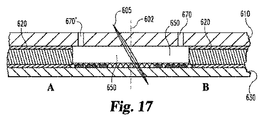
一実施形態において、角度をつけた切断具(上部および/または下部基板層に対して角度がつけられた)が列AおよびBを分離するのに使用される。図17〜20に示されるように、角度をつけた切断具605は、上部基板層610、下部基板層630、取り囲むスペーサ620および毛管チャンバ650が中心線602から異なる距離で伸びるテストストリップを製造する。図17による切断によってできるような、角度をつけた一度の切断がなされたとき、列Aの突き出た距離は、列Bの逆と同じである。図18に示されるような2つの切断具605Aおよび605Bを使用する場合、それぞれの列から分離されたストリップがほぼ同じ突き出た構造となるように、2つの反対に角度をつけた切断が反対の方向でなされる。異なる突き出た距離を有する例示的実施形態の図示は、図19および20にされている。
In one embodiment, angled cutting tools (angled with respect to the upper and / or lower substrate layers) are used to separate rows A and B. As shown in FIGS. 17-20, the
本発明のある実施形態では、下部基板層(たとえば下部基板層130)は通常、絶縁基板の10ミル(0.01インチ)のストリップで構成され、絶縁基板はたとえば、ポリエチレンテレフタレート(PET、たとえばイー・アイ・デュポン・ド・ヌムール・アンド・カンパニーにより製造されたMelinex(登録商標))、ポリエチレンナフタレート(PEN)、ポリビニルクロライド(PVC)、ポリイミド(PI)またはポリカーボネート(PC)フィルムである。他の実施形態では、電極および電極パターン(たとえば、収集端部電極パターン155)は、レーザーアブレーションまたは相対的に小さな検査領域において良好に区画された電極パターンを作るのに適切な他の技術を用いて、下部基板層の上部に形成される。電極はたとえば、金、パラジウム、白金、炭素をスパッタ、印刷またはインクジェットすることにより形成することができる。スペーサ層(たとえばスペーサ層120)は、不透明にすることができ、テストストリップおよび/またはそのテストストリップの使用する方向を識別する表示のような印刷または表示を含むことができる。 In some embodiments of the present invention, the lower substrate layer (eg, lower substrate layer 130) is typically comprised of a 10 mil (0.01 inch) strip of insulating substrate, which may be, for example, polyethylene terephthalate (PET, eg, eA). • Melinex (registered trademark), polyethylene naphthalate (PEN), polyvinyl chloride (PVC), polyimide (PI) or polycarbonate (PC) film manufactured by I DuPont de Nemours & Company. In other embodiments, the electrodes and electrode patterns (eg, collection end electrode patterns 155) use laser ablation or other techniques suitable for creating well-defined electrode patterns in relatively small inspection areas. And formed on the lower substrate layer. The electrode can be formed, for example, by sputtering, printing, or inkjetting gold, palladium, platinum, or carbon. The spacer layer (eg, spacer layer 120) can be opaque and can include a print or display such as a display that identifies the test strip and / or the direction in which the test strip is to be used.
図21に示すのは、本発明の他の実施形態によるテストストリップ500である。テストストリップ500は下部基板層510を含む。テストストリップ500はまた下部基板510上に設けられた接触パッドパターン512および電極パターン514を含んでいる。試薬層515(透明なものとして示されている)は、電極パターン514と、電極パターン514により覆われていない電極パターン514の近傍における下部基板層514の部分とを覆っている。電極パターン514は収集端部516に位置付けられる一方、接触パッドパターン512は検査器接続端部518に位置付けられる。スペーサ層520は、基板層510、接触パッドパターン512および電極パターン514を覆っている。電極およびスペーサ層の図示をより明瞭にするために上部基板層は図21においては図示されていないが、テストストリップ500はさらに上部基板層を含んでいる。
Shown in FIG. 21 is a
収集端部516はテストストリップ500の長手軸522に垂直ではない。その代わりに、収集端部516は長手軸522から垂直ではない角度524の角度で傾斜している。すなわち、角度524は90度ではない。テストストリップの特定される横方向の幅について、角度がつけられた収集端部516は、長手軸に対して垂直な収集端部を有する典型的なテストストリップよりも試料を適用するユーザにとってより広いチャンバ開口部を与える。患者、特に手の器用さが衰えた患者は、より長く、角度のついた縁部がより容易に使用できることに気付く。角度のついた収集端部516のより広いチャンバ開口部は、たとえばテストストリップの横幅が5mm以下のように相対的に幅が狭いテストストリップで使用したときに特に有利である。
The
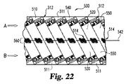
図22に示すのは、本発明の一実施形態によるテストストリップ500を製造する製造プロセスの間の部分的に構築された複数のテストストリップ530である。接触パッドパターン512と収集端部電極パターン514は、下部基板510の伸長したテープ540上に形成される。接触パッドパターン512および電極パターン514は、たとえばレーザーアブレーション技術を用いて、伸長した下部基板テープ540の上部に形成される。テープ540は、長手軸542を画定し、電極パターン(電極パターン514および接触パッド512を含む)は、長手軸542に対して角度がつけられている。スペーサ層520を形成する材料の2つの伸長したテープ550は、電極パターンおよび下部基板テープ540上に積層される。試薬層ストライプ560(透明なものとして示されている)は、試料チャンバを形成する電極パターン514と伸長した下部基板テープ540とを覆って積層される。ラチェットカットする切断装置は、下部基板テープ540の余分な材料511を取り除く。同様のラチェットカット装置を、それぞれの伸長したスペーサ層テープ550の縁部を作るのに用いることができる。
Shown in FIG. 22 is a plurality of partially constructed
伸長したスペーサテープ550および試薬層ストライプ560が伸長した下部基板層540および電極パターンに取り付けられた後、伸長した上部基板テープが適用される(テストストリップの他の部分の詳細を示すために図示していない)。テストストリップは、長手軸542に沿って列Bのテストストリップから列Aのテストストリップを分離する分離プロセスを使用して互いに分離される。余分な材料511が、たとえばラチェットカット技術によりそれぞれの列から最初に分離されるが、隣接するテストストリップは、それぞれのストリップの側面に沿って直線的な切断により分離される。
After the
本発明の図示した実施例、代表的な実施形態および特定の形状は、図面および前述した記載において詳細に図示および説明したが、これらは例示として考えられ、制限または限定するものではない。一実施形態における特定の特徴についての記載は、それぞれの特定の特徴が必ずしもその実施形態に限定されることを意味するものではない。一実施形態の特徴は、そのように明示的に記載されていてもいなくても、この技術分野における当業者に理解されるように、他の実施形態と組み合わせて使用することができる。寸法は明示的に使用されようが、暗示的に使用されようが、限定することを意図したものではなく、この技術分野の当業者により理解されるように、変更することが可能である。例示的な実施形態のみが示され、説明されているが、本発明の趣旨の範囲内で生じる全ての変更、修正は保護されるべきである。 While the illustrated examples, exemplary embodiments and specific shapes of the present invention have been illustrated and described in detail in the drawings and foregoing description, they are considered illustrative and not restrictive or limiting. The recitation of particular features in one embodiment does not imply that each particular feature is necessarily limited to that embodiment. The features of one embodiment may be used in combination with other embodiments, whether or not explicitly described as such, as will be appreciated by those skilled in the art. The dimensions, whether used explicitly or implicitly, are not intended to be limiting and can be varied as will be understood by those skilled in the art. Although only exemplary embodiments have been shown and described, all changes and modifications that occur within the spirit of the invention should be protected.
Claims (20)
連続した基板(330、540、630、510)の内側に沿って列をなす同様な電極のセット(301、355、514)の多数の対を形成する工程であって、電極のセットのそれぞれの対が、第1の電極セットと、対をなして頭を向かい合わせて配置された第2の電極セットとを備え、前記第1の電極セットが前記基板に沿って第1の列を形成するように揃えられ、前記第2の電極セットが前記基板に沿って第2の列を形成するように揃えられ、第1の電極セットのそれぞれが、対をなす前記第2の電極セットと隣り合うが、前記第2の電極セットから所定の距離離間している、電極のセットの多数の対を形成する工程と、
前記電極のセットのそれぞれを少なくとも部分的に覆う試薬(352、560、515)を付着する工程と、
前記連続した基板の上部に、対をなす電極のセットの両方を覆うようにスペーサ層(320、620、520)およびカバー層(310、610)を積層する工程であって、前記スペーサ層(320、620、520)が、前記第1の電極セットと前記第2の電極セットとの間の中心線(331、602、542)上に、かつ該中心線に沿って配置された複数の開口部(348、148)を備え、前記複数の開口部のそれぞれが、前記電極のセットのそれぞれの対と並び、前記複数の開口部(348、148)のそれぞれが、前記電極のセットのそれぞれの対に対応して完成したテストストリップにおける毛管チャンバ(150、650、350)を形成している、前記連続した基板の上部にスペーサ層およびカバー層を積層する工程と、
前記第1の電極セットを前記第2の電極セットから分離する工程であって、該分離する工程により、それぞれのテストストリップの端部から少なくとも前記テストストリップの電極のセットまで延びる毛管チャンバ(150、650、350)を有するテストストリップが形成される、分離する工程と、
一度または複数回の切断により、第1の電極セットのそれぞれを、第1の電極セットの他のそれぞれから分離し、第2の電極セットのそれぞれを、第2の電極セットの他のそれぞれから分離する工程とを備え、
それにより個々のテストストリップを形成するバイオセンサテストストリップの製造方法。 A method of manufacturing a biosensor test strip (100, 302, 304, 500), comprising:
Forming multiple pairs of similar sets of electrodes (301, 355, 514) in rows along the inside of a continuous substrate (330, 540, 630, 510), each of the sets of electrodes A pair comprises a first electrode set and a second electrode set arranged in pairs and facing heads, wherein the first electrode set forms a first row along the substrate And the second electrode set is aligned to form a second row along the substrate, and each of the first electrode sets is adjacent to the paired second electrode set Forming a number of pairs of sets of electrodes spaced a predetermined distance from the second set of electrodes;
Attaching a reagent (352, 560, 515) that at least partially covers each of the set of electrodes;
A step of laminating a spacer layer (320, 620, 520) and a cover layer (310, 610) on the continuous substrate so as to cover both of the pair of electrode sets, the spacer layer (320 , 620, 520) are disposed on and along the center line (331, 602, 542) between the first electrode set and the second electrode set. (348, 148), wherein each of the plurality of openings is aligned with a respective pair of the set of electrodes, and each of the plurality of openings (348, 148) is a respective pair of the set of electrodes. Laminating a spacer layer and a cover layer on top of the continuous substrate forming a capillary chamber (150, 650, 350) in a completed test strip corresponding to
Separating the first electrode set from the second electrode set , wherein the separating step extends from the end of each test strip to at least the set of electrodes of the test strip (150, 650, 350) to form a test strip ;
Separating each of the first electrode sets from each other of the first electrode sets and separating each of the second electrode sets from each of the other of the second electrode sets by one or more cuts Comprising the steps of:
A biosensor test strip manufacturing method whereby individual test strips are formed.
連続した基板(330、510)上に、頭が向かい合った同様な電極のセット(355、514)の第1および第2の列を形成する工程と、
前記第1の列の電極のセットを少なくとも部分的に覆う連続した第1の試薬層(352、352A)を付着する工程と、
前記第2の列の電極のセットを少なくとも部分的に覆う連続した第2の試薬層(352、352B)を付着する工程と、
前記連続した基板の上部に、前記頭が向かい合った同様な電極のセットの両方を覆うようにスペーサ層(320、620、520)およびカバー層(310、610)を積層する工程であって、前記スペーサ層(320、620、520)が、前記第1の列の電極のセットと前記第2の列の電極のセットとの間の中心線(331、602、542)上に、かつ該中心線に沿って配置された複数の切欠部(348、148)を備え、前記複数の切欠部のそれぞれが、前記頭が向かい合った同様な電極のセットと並び、前記複数の切欠部(348、148)のそれぞれが、前記頭が向かい合った同様な電極のセットに対応して完成したテストストリップにおける毛管チャンバ(150、650、350)を形成している、前記連続した基板の上部にスペーサ層およびカバー層を積層する工程と、
前記基板を個々のテストストリップに分離する工程とを備え、
前記分離する工程が、頭が向かい合った電極のセットの2つの列の間で基板を切断する工程を含み、
前記分離する工程により、それぞれのテストストリップの端部から少なくとも前記テストストリップの電極のセットまで延びる毛管チャンバ(150、650、350)を有するテストストリップが形成される製造方法。 A method of manufacturing a biosensor test strip (100, 302, 304, 500), comprising:
Forming first and second rows of similar sets of electrodes (355, 514) head-to-face on a continuous substrate (330, 510);
Depositing a continuous first reagent layer (352, 352A) that at least partially covers the set of electrodes in the first row;
Depositing a continuous second reagent layer (352, 352B) that at least partially covers the set of electrodes in the second row;
Laminating a spacer layer (320, 620, 520) and a cover layer (310, 610) on top of the continuous substrate so as to cover both sets of similar electrodes facing the head, A spacer layer (320, 620, 520) is on and centerline (331, 602, 542) between the first row of electrode sets and the second row of electrode sets. A plurality of notches (348, 148) arranged along each of the plurality of notches, each lined up with a similar set of electrodes facing the head, and the plurality of notches (348, 148). Each of which forms a capillary chamber (150, 650, 350) in a completed test strip corresponding to a similar set of electrodes facing each other. Laminating a spacer layer and cover layer,
Separating the substrate into individual test strips,
Wherein the step of separation, seen contains a step of cutting the substrate between the two rows of the set of head facing electrodes,
Method of manufacturing wherein the separating step forms a test strip having capillary chambers (150, 650, 350) extending from the end of each test strip to at least the set of electrodes of the test strip .
前記連続したカバー層にベント開口部(370、370´、670、670´)を形成する工程と、
前記毛管チャンバ用にベントを作るために、前記ベント開口部(370、370´、670、670´)を前記切欠部に並べる工程とを備える請求項13記載の製造方法。 The manufacturing method further includes:
Forming vent openings (370, 370 ′, 670, 670 ′) in the continuous cover layer;
Wherein in order to make a vent for capillary chamber, wherein the vent opening (370,370', 670,670') The method of claim 13 further comprising the step of arranging the cutout portion.
連続した基板(130、330、510、630)上に、2列の電極のセット(155、301、355、514)を形成する工程と、
前記2列の電極のセット(155、301、355、514)を少なくとも部分的に覆う試薬層(152、352、515)を付着する工程と、
前記連続した基板の上部に複数の切欠部(148、348)を画定する連続したスペーサ層を積層する工程であって、前記複数の切欠部が、前記2列の電極のセットの間の中心線(331、602、542)上に、かつ該中心線に沿って配置され、単一の切欠部(148、348)が、前記2列の電極のセットにおける電極のセット(155、355、301、514)のそれぞれの対と並んでおり、前記単一の切欠部が、前記電極のセットのそれぞれの対に対応して完成したテストストリップにおいて毛管チャンバ(150、650、350)を形成している、連続したスペーサ層(120、320、520、630)を積層する工程と、
毛管チャンバ(150、650、350)を作るために、前記連続したスペーサ層の上部に複数のベント開口部(170、171、370、370´、670、670´)を有する連続したカバー層(110、310、610)を積層する工程と、
それぞれの毛管チャンバ用に少なくとも2つのベントを作るために、前記ベント開口部(170、171、370、370´、670、670´)の少なくとも2つを前記スペーサ層のそれぞれの切欠部(148、348)に並べる工程と、
前記基板、前記スペーサ層(120、320)および前記カバー層(110、310)を個々のバイオセンサテストストリップに分離する工程とを備え、
前記分離する工程により、それぞれのテストストリップの端部から少なくとも前記テストストリップの電極のセットまで延びる毛管チャンバ(150、650、350)を有するテストストリップが形成される製造方法。 A method of manufacturing a biosensor test strip, comprising:
On continuous substrate (130,330,510,630), forming a set of two rows of electrodes (155,301,355,514),
Depositing a reagent layer (152, 352, 515 ) that at least partially covers the two rows of electrode sets (155, 301, 355, 514 ) ;
Laminating a continuous spacer layer defining a plurality of notches (148, 348) on top of the continuous substrate, wherein the plurality of notches are centerlines between the two sets of electrodes; (331, 602, 542) and along the center line, a single notch (148, 348) is a set of electrodes (155, 355, 301, is aligned with a respective pair of 514), it said single notch is forms a capillary chamber (150,650,350) in the test strip was completed in correspondence to each pair of the set of electrodes a step of laminating a continuous spacer layer (120,320,520,630),
To create a capillary chamber (150, 650, 350), a continuous cover layer (110) having a plurality of vent openings (170, 171, 370, 370 ′, 670, 670 ′) on top of the continuous spacer layer. 310, 610), and
In order to create at least two vents for each capillary chamber, at least two of the vent openings (170, 171, 370, 370 ′, 670, 670 ′) are connected to respective notches (148, 148, of the spacer layer). 348), and
Separating the substrate, the spacer layer (120, 320) and the cover layer (110, 310) into individual biosensor test strips ;
Wherein the separating method of the test strip Ru is formed to have a capillary chamber (150,650,350) extending from the end of each test strip to a set of at least the test strip electrodes.
Applications Claiming Priority (3)
| Application Number | Priority Date | Filing Date | Title |
|---|---|---|---|
| US36001010P | 2010-06-30 | 2010-06-30 | |
| US61/360,010 | 2010-06-30 | ||
| PCT/US2011/042574 WO2012003306A1 (en) | 2010-06-30 | 2011-06-30 | Methods for manufacturing a dual biosensor test strip |
Publications (3)
| Publication Number | Publication Date |
|---|---|
| JP2013530408A JP2013530408A (en) | 2013-07-25 |
| JP2013530408A5 JP2013530408A5 (en) | 2013-09-26 |
| JP5580934B2 true JP5580934B2 (en) | 2014-08-27 |
Family
ID=44511683
Family Applications (1)
| Application Number | Title | Priority Date | Filing Date |
|---|---|---|---|
| JP2013518702A Expired - Fee Related JP5580934B2 (en) | 2010-06-30 | 2011-06-30 | Method for manufacturing a dual biosensor test strip |
Country Status (8)
| Country | Link |
|---|---|
| US (1) | US20130105074A1 (en) |
| EP (1) | EP2588857A1 (en) |
| JP (1) | JP5580934B2 (en) |
| KR (1) | KR20130023287A (en) |
| CN (1) | CN103038637A (en) |
| CA (1) | CA2801946A1 (en) |
| MX (1) | MX2012014620A (en) |
| WO (1) | WO2012003306A1 (en) |
Cited By (1)
| Publication number | Priority date | Publication date | Assignee | Title |
|---|---|---|---|---|
| KR102226295B1 (en) * | 2019-10-15 | 2021-03-10 | 주식회사 비바이오 | Biomaterial sensing strip and method for manufacturing same |
Families Citing this family (15)
| Publication number | Priority date | Publication date | Assignee | Title |
|---|---|---|---|---|
| US11360076B2 (en) | 2012-03-30 | 2022-06-14 | Weavr Health Corp. | Methods and systems to collect a biological sample |
| US20130341207A1 (en) * | 2012-06-21 | 2013-12-26 | Lifescan Scotland Limited | Analytical test strip with capillary sample-receiving chambers separated by stop junctions |
| US8921061B2 (en) | 2012-11-02 | 2014-12-30 | Roche Diagnostics Operations, Inc. | Reagent materials and associated test elements |
| US8920628B2 (en) | 2012-11-02 | 2014-12-30 | Roche Diagnostics Operations, Inc. | Systems and methods for multiple analyte analysis |
| US11358138B2 (en) | 2013-07-19 | 2022-06-14 | Boston Microfluidics Inc. | Fluid sample collection device |
| US10036709B2 (en) * | 2014-05-20 | 2018-07-31 | Roche Diabetes Care, Inc. | BG meter illuminated test strip |
| CA2955198C (en) * | 2014-07-17 | 2017-10-10 | Siemens Healthcare Diagnostics Inc. | Sensor array |
| WO2016073395A1 (en) | 2014-11-03 | 2016-05-12 | Roche Diabetes Care, Inc. | Electrode arrangements for electrochemical test elements and methods of use thereof |
| US11382185B2 (en) * | 2016-01-08 | 2022-07-05 | Siemens Healthcare Diagnostics Inc. | Heating element for sensor array |
| EP3701261A4 (en) | 2017-10-27 | 2021-08-04 | Boston Microfluidics, Inc. | Fluid sample collection device |
| US11484877B2 (en) | 2018-05-29 | 2022-11-01 | Weavr Health Corp. | Blood metering device with desiccant and support for storage media and inlay with flange |
| US11772097B2 (en) | 2018-10-19 | 2023-10-03 | Renegadexbio, Pbc | Simultaneous spot test and storage of blood samples |
| WO2020086397A1 (en) | 2018-10-23 | 2020-04-30 | Boston Microfluidics, Inc. | Funnel with extension tube to augment blood collection device |
| EP4025129A4 (en) * | 2019-09-06 | 2024-02-14 | Renegadexbio Pbc | Medium with hydrophobic patterns and break lines defining a blood collection volume |
| JP2023534958A (en) * | 2020-07-17 | 2023-08-15 | トラスティーズ オブ ボストン ユニバーシティ | Virus detection system and its use |
Family Cites Families (13)
| Publication number | Priority date | Publication date | Assignee | Title |
|---|---|---|---|---|
| US5141868A (en) * | 1984-06-13 | 1992-08-25 | Internationale Octrooi Maatschappij "Octropa" Bv | Device for use in chemical test procedures |
| US5997817A (en) | 1997-12-05 | 1999-12-07 | Roche Diagnostics Corporation | Electrochemical biosensor test strip |
| US20050103624A1 (en) * | 1999-10-04 | 2005-05-19 | Bhullar Raghbir S. | Biosensor and method of making |
| EP1167538A1 (en) * | 2000-06-30 | 2002-01-02 | Schibli Engineering GmbH | Biosensor and method for its production |
| US6800488B2 (en) * | 2000-12-13 | 2004-10-05 | Lifescan, Inc. | Methods of manufacturing reagent test strips |
| US8071030B2 (en) * | 2003-06-20 | 2011-12-06 | Roche Diagnostics Operations, Inc. | Test strip with flared sample receiving chamber |
| PL1639354T3 (en) * | 2003-06-20 | 2018-11-30 | F.Hoffmann-La Roche Ag | Test strip with slot vent opening |
| EP1667581A1 (en) * | 2003-09-01 | 2006-06-14 | Inverness Medical Switzerland GmbH | Sampling device with capillary action |
| AU2004284368B2 (en) * | 2003-10-29 | 2008-11-20 | Agency For Science, Technology And Research | Biosensor |
| US20050247573A1 (en) * | 2004-03-23 | 2005-11-10 | Hideaki Nakamura | Biosensors |
| US7465597B2 (en) * | 2006-06-29 | 2008-12-16 | Home Diagnostics, Inc. | Method of manufacturing a diagnostic test strip |
| EP3660499A1 (en) * | 2007-09-24 | 2020-06-03 | Ascensia Diabetes Care Holdings AG | Multi-electrode test sensor |
| EP2261646B1 (en) * | 2008-03-27 | 2015-07-29 | Panasonic Healthcare Holdings Co., Ltd. | Measurement device, measurement system, and concentration measurement method |
-
2011
- 2011-06-30 EP EP11731224.9A patent/EP2588857A1/en not_active Withdrawn
- 2011-06-30 CA CA2801946A patent/CA2801946A1/en not_active Abandoned
- 2011-06-30 WO PCT/US2011/042574 patent/WO2012003306A1/en active Application Filing
- 2011-06-30 MX MX2012014620A patent/MX2012014620A/en not_active Application Discontinuation
- 2011-06-30 KR KR1020127034266A patent/KR20130023287A/en active IP Right Grant
- 2011-06-30 JP JP2013518702A patent/JP5580934B2/en not_active Expired - Fee Related
- 2011-06-30 CN CN2011800326744A patent/CN103038637A/en active Pending
-
2012
- 2012-12-12 US US13/712,072 patent/US20130105074A1/en not_active Abandoned
Cited By (1)
| Publication number | Priority date | Publication date | Assignee | Title |
|---|---|---|---|---|
| KR102226295B1 (en) * | 2019-10-15 | 2021-03-10 | 주식회사 비바이오 | Biomaterial sensing strip and method for manufacturing same |
Also Published As
| Publication number | Publication date |
|---|---|
| KR20130023287A (en) | 2013-03-07 |
| MX2012014620A (en) | 2013-02-07 |
| EP2588857A1 (en) | 2013-05-08 |
| WO2012003306A1 (en) | 2012-01-05 |
| JP2013530408A (en) | 2013-07-25 |
| CN103038637A (en) | 2013-04-10 |
| US20130105074A1 (en) | 2013-05-02 |
| CA2801946A1 (en) | 2012-01-05 |
Similar Documents
| Publication | Publication Date | Title |
|---|---|---|
| JP5580934B2 (en) | Method for manufacturing a dual biosensor test strip | |
| US8992750B1 (en) | Biosensor and methods for manufacturing | |
| CN1307420C (en) | Physiological sample collector and use method thereof | |
| US7060192B2 (en) | Methods of fabricating physiological sample collection devices | |
| KR20030013260A (en) | Devices for analyte concentration determination and methods of using the same | |
| ES2379219T3 (en) | Analyte test strip that accepts various sample volumes | |
| JP2015520394A (en) | Analytical test strip with capillary sample storage chamber separated by a physical barrier island | |
| ES2672729T3 (en) | Analytical test strip with electrochemical base with cross-receiving sample chambers | |
| JP6259903B2 (en) | Biosensor | |
| JP6154538B2 (en) | Biosensor and manufacturing method thereof | |
| JP2020197541A (en) | Test element for electrochemically detecting at least one analyte | |
| JP4138512B2 (en) | Body fluid collection tool | |
| CN203535003U (en) | Biosensor | |
| CN203324219U (en) | Biosensor | |
| JP2015520393A (en) | Analytical test strip with capillary sample receiving chamber separated by partition junction | |
| US20150233861A1 (en) | Test sensor with multiple sampling routes | |
| US8308923B2 (en) | Biosensor strip | |
| TW201501694A (en) | Analytical test strip with capillary sample-receiving chambers separated by a physical barrier island | |
| BR112017011033B1 (en) | SYSTEM FOR DETERMINING AT LEAST ONE PROPERTY OF A SAMPLE AND METHOD FOR DETERMINING AT LEAST ONE PROPERTY OF A SAMPLE |
Legal Events
| Date | Code | Title | Description |
|---|---|---|---|
| A529 | Written submission of copy of amendment under section 34 (pct) |
Free format text: JAPANESE INTERMEDIATE CODE: A529 Effective date: 20121227 |
|
| A521 | Written amendment |
Free format text: JAPANESE INTERMEDIATE CODE: A523 Effective date: 20130729 |
|
| A621 | Written request for application examination |
Free format text: JAPANESE INTERMEDIATE CODE: A621 Effective date: 20130729 |
|
| A131 | Notification of reasons for refusal |
Free format text: JAPANESE INTERMEDIATE CODE: A131 Effective date: 20131119 |
|
| A977 | Report on retrieval |
Free format text: JAPANESE INTERMEDIATE CODE: A971007 Effective date: 20131122 |
|
| A601 | Written request for extension of time |
Free format text: JAPANESE INTERMEDIATE CODE: A601 Effective date: 20140213 |
|
| A602 | Written permission of extension of time |
Free format text: JAPANESE INTERMEDIATE CODE: A602 Effective date: 20140220 |
|
| A601 | Written request for extension of time |
Free format text: JAPANESE INTERMEDIATE CODE: A601 Effective date: 20140409 |
|
| A602 | Written permission of extension of time |
Free format text: JAPANESE INTERMEDIATE CODE: A602 Effective date: 20140416 |
|
| A521 | Written amendment |
Free format text: JAPANESE INTERMEDIATE CODE: A523 Effective date: 20140514 |
|
| RD02 | Notification of acceptance of power of attorney |
Free format text: JAPANESE INTERMEDIATE CODE: A7422 Effective date: 20140514 |
|
| TRDD | Decision of grant or rejection written | ||
| A01 | Written decision to grant a patent or to grant a registration (utility model) |
Free format text: JAPANESE INTERMEDIATE CODE: A01 Effective date: 20140624 |
|
| A61 | First payment of annual fees (during grant procedure) |
Free format text: JAPANESE INTERMEDIATE CODE: A61 Effective date: 20140711 |
|
| R150 | Certificate of patent or registration of utility model |
Ref document number: 5580934 Country of ref document: JP Free format text: JAPANESE INTERMEDIATE CODE: R150 |
|
| LAPS | Cancellation because of no payment of annual fees |