JP2020197541A - Test element for electrochemically detecting at least one analyte - Google Patents
Test element for electrochemically detecting at least one analyte Download PDFInfo
- Publication number
- JP2020197541A JP2020197541A JP2020143174A JP2020143174A JP2020197541A JP 2020197541 A JP2020197541 A JP 2020197541A JP 2020143174 A JP2020143174 A JP 2020143174A JP 2020143174 A JP2020143174 A JP 2020143174A JP 2020197541 A JP2020197541 A JP 2020197541A
- Authority
- JP
- Japan
- Prior art keywords
- electrode
- layer
- inspection element
- inspection
- capillary
- Prior art date
- Legal status (The legal status is an assumption and is not a legal conclusion. Google has not performed a legal analysis and makes no representation as to the accuracy of the status listed.)
- Pending
Links
Images


Classifications
-
- G—PHYSICS
- G01—MEASURING; TESTING
- G01N—INVESTIGATING OR ANALYSING MATERIALS BY DETERMINING THEIR CHEMICAL OR PHYSICAL PROPERTIES
- G01N27/00—Investigating or analysing materials by the use of electric, electrochemical, or magnetic means
- G01N27/26—Investigating or analysing materials by the use of electric, electrochemical, or magnetic means by investigating electrochemical variables; by using electrolysis or electrophoresis
- G01N27/28—Electrolytic cell components
- G01N27/30—Electrodes, e.g. test electrodes; Half-cells
- G01N27/327—Biochemical electrodes, e.g. electrical or mechanical details for in vitro measurements
- G01N27/3271—Amperometric enzyme electrodes for analytes in body fluids, e.g. glucose in blood
- G01N27/3272—Test elements therefor, i.e. disposable laminated substrates with electrodes, reagent and channels
-
- C—CHEMISTRY; METALLURGY
- C12—BIOCHEMISTRY; BEER; SPIRITS; WINE; VINEGAR; MICROBIOLOGY; ENZYMOLOGY; MUTATION OR GENETIC ENGINEERING
- C12Q—MEASURING OR TESTING PROCESSES INVOLVING ENZYMES, NUCLEIC ACIDS OR MICROORGANISMS; COMPOSITIONS OR TEST PAPERS THEREFOR; PROCESSES OF PREPARING SUCH COMPOSITIONS; CONDITION-RESPONSIVE CONTROL IN MICROBIOLOGICAL OR ENZYMOLOGICAL PROCESSES
- C12Q1/00—Measuring or testing processes involving enzymes, nucleic acids or microorganisms; Compositions therefor; Processes of preparing such compositions
- C12Q1/001—Enzyme electrodes
- C12Q1/005—Enzyme electrodes involving specific analytes or enzymes
- C12Q1/006—Enzyme electrodes involving specific analytes or enzymes for glucose
-
- G—PHYSICS
- G01—MEASURING; TESTING
- G01N—INVESTIGATING OR ANALYSING MATERIALS BY DETERMINING THEIR CHEMICAL OR PHYSICAL PROPERTIES
- G01N27/00—Investigating or analysing materials by the use of electric, electrochemical, or magnetic means
- G01N27/02—Investigating or analysing materials by the use of electric, electrochemical, or magnetic means by investigating impedance
- G01N27/04—Investigating or analysing materials by the use of electric, electrochemical, or magnetic means by investigating impedance by investigating resistance
-
- G—PHYSICS
- G01—MEASURING; TESTING
- G01N—INVESTIGATING OR ANALYSING MATERIALS BY DETERMINING THEIR CHEMICAL OR PHYSICAL PROPERTIES
- G01N27/00—Investigating or analysing materials by the use of electric, electrochemical, or magnetic means
- G01N27/26—Investigating or analysing materials by the use of electric, electrochemical, or magnetic means by investigating electrochemical variables; by using electrolysis or electrophoresis
- G01N27/28—Electrolytic cell components
- G01N27/30—Electrodes, e.g. test electrodes; Half-cells
- G01N27/327—Biochemical electrodes, e.g. electrical or mechanical details for in vitro measurements
- G01N27/3271—Amperometric enzyme electrodes for analytes in body fluids, e.g. glucose in blood
- G01N27/3274—Corrective measures, e.g. error detection, compensation for temperature or hematocrit, calibration
-
- G—PHYSICS
- G01—MEASURING; TESTING
- G01N—INVESTIGATING OR ANALYSING MATERIALS BY DETERMINING THEIR CHEMICAL OR PHYSICAL PROPERTIES
- G01N33/00—Investigating or analysing materials by specific methods not covered by groups G01N1/00 - G01N31/00
- G01N33/48—Biological material, e.g. blood, urine; Haemocytometers
- G01N33/483—Physical analysis of biological material
- G01N33/487—Physical analysis of biological material of liquid biological material
Abstract
Description
本発明は、少なくとも1つの分析物を電気化学的に検出するための検査エレメント、この検査エレメントを生産するための方法、および試料の少なくとも1つの性質を判定するためのシステムを開示するものである。本発明による方法およびデバイスは、体組織または体液の一方または両方に存在する少なくとも1つの分析物を検出するために使用されてよく、特に、これらの方法およびデバイスは、専門家による診断の分野と在宅モニタリングの分野の両方において、血液、好ましくは全血、血漿、血清、尿、唾液、間質液、または他の体液などの体液中の、グルコース、乳酸塩、トリグリセリド、コレステロール、または他の分析物、好ましくは代謝産物などの、1つまたは複数の分析物を検出する分野において適用される。しかしながら、他の適用分野も実行可能である。 The present invention discloses a test element for electrochemically detecting at least one analyte, a method for producing the test element, and a system for determining at least one property of a sample. .. The methods and devices according to the invention may be used to detect at least one analyte present in one or both of body tissues and fluids, in particular these methods and devices are in the field of expert diagnosis. Glucose, lactate, triglyceride, cholesterol, or other analysis in body fluids such as blood, preferably whole blood, plasma, serum, urine, saliva, interstitial fluid, or other body fluids, both in the field of home monitoring. It is applied in the field of detecting one or more analytes, such as objects, preferably metabolites. However, other areas of application are also feasible.
医療技術および診断の分野では、体液中の少なくとも1つの分析物を検出するための多数のデバイスおよび方法が知られている。これらの方法およびデバイスは、体組織または体液の一方または両方に存在する少なくとも1つの分析物、特に、血液、好ましくは全血、血漿、血清、尿、唾液、間質液、または他の体液などの体液中の、グルコース、乳酸塩、トリグリセリド、コレステロール、または他の分析物、好ましくは代謝産物などの、1つまたは複数の分析物を検出するために使用され得る。さらに、凝固モニタリングの目的で、活性時間を測定する、たとえばトロンビン活性化時間測定のためのデバイスが知られている。以下では、本発明の範囲を制限することなく、主に、例示的で好ましい分析物としてグルコースの判定に対する参照がなされる。 In the field of medical technology and diagnosis, a number of devices and methods are known for detecting at least one analyte in body fluids. These methods and devices include at least one analyte present in one or both of body tissues and fluids, particularly blood, preferably whole blood, plasma, serum, urine, saliva, interstitial fluid, or other bodily fluids. Can be used to detect one or more analyzes in body fluids such as glucose, lactate, triglyceride, cholesterol, or other analysts, preferably metabolites. Further, for the purpose of coagulation monitoring, a device for measuring the activity time, for example, for measuring the thrombin activation time, is known. In the following, without limiting the scope of the present invention, references are made primarily to the determination of glucose as exemplary and preferred analytes.
血糖濃度の判定ならびに対応する薬物療法は、多くの糖尿病患者にとって毎日のルーチンの不可欠な部分である。利便性を向上させるために、および許容可能な程度以上に毎日のルーチンを制限することを回避するために、自宅から離れたところでの仕事、余暇、または他の活動中に血糖濃度を測定するなどのためのポータブルデバイスおよび検査エレメントが当技術分野で知られている。一方、多数の検査デバイスが市販されている。検査ストリップの形をとる検査エレメントの使用に基づいた多数の検査デバイスおよび検査システムが知られている。マガジン(magazine)によって複数の検査ストリップが提供される適用例が知られており、これらの適用例では、マガジンからの検査ストリップは、検査用デバイスに自動的に提供され得る。しかしながら、単一の検査ストリップが使用される他の適用例も知られており、これらの検査ストリップは、使用者によって手動で検査用デバイスに挿入される。その中で、一般には、検査ストリップの端は、検査用デバイスに挿入されるように、および分析物を検出するために適合され、検査ストリップの対向する端は、使用者が検査ストリップを検査用デバイスに押し込むまたは検査ストリップを検査用デバイスから除去することを可能にするハンドルとして働く。試料を検査エレメントに適用するために、一般的な検査エレメントは、毛細管検査エレメント内の毛細管開口または上部投与システムを有する光学的検査ストリップ内のスプライトネット(sprite net)などの、少なくとも1つの試料適用部位を提供する。このタイプの検査ストリップは、たとえばAccu−Chek Active(登録商標)という商品名で市販されている。在宅看護適用例の代わりに、そのような検査エレメントが、病院適用例においてなどの、専門家による診断において使用され得る。 Determining blood glucose levels and corresponding medications are an integral part of the daily routine for many diabetics. To improve convenience and to avoid limiting daily routines beyond acceptable levels, such as measuring blood glucose levels during work, leisure, or other activities away from home. Portable devices and inspection elements for are known in the art. On the other hand, many inspection devices are commercially available. Numerous inspection devices and systems are known based on the use of inspection elements in the form of inspection strips. There are known applications in which multiple inspection strips are provided by the magazine, in which inspection strips from the magazine may be automatically provided to the inspection device. However, other applications where a single test strip is used are also known, and these test strips are manually inserted into the test device by the user. Among them, in general, the ends of the inspection strip are adapted to be inserted into the inspection device and to detect the analyte, and the opposite ends of the inspection strip are for the user to inspect the inspection strip. Acts as a handle that allows you to push into the device or remove the inspection strip from the inspection device. To apply a sample to a test element, a common test element is at least one sample application, such as a capillary opening in a capillary test element or a sprite net in an optical test strip with an upper administration system. Provide the site. This type of inspection strip is commercially available, for example, under the trade name Accu-Chek Active®. Instead of home nursing applications, such test elements can be used in professional diagnosis, such as in hospital applications.
多くの場合、分析物を検出するために、1つまたは複数の検査化学物質(test chemistry)を有する1つまたは複数の検査分野を備える、検査ストリップなどの検査エレメントが使用される。これらの検査化学物質は、検出されるべき分析物の存在下で1つまたは複数の検出可能な性質を変更するように適合される。したがって、検査化学
物質の電気化学的に検出可能な性質および/または検査化学物質の光学的に検出可能な性質が、分析物の存在の影響により変更され得る。本明細書内で使用され得る潜在的な検査化学物質については、J.Honesら:Diabetes Technology and Therapeutics(糖尿病技術および治療法)、第10巻、補遺1、2008年、S−10〜S−26を参照されたい。しかしながら、他のタイプの検査化学物質が本発明内で使用されてもよい。
Often, a test element, such as a test strip, comprising one or more test areas with one or more test chemistries is used to detect the analyte. These test chemicals are adapted to alter one or more detectable properties in the presence of the analyte to be detected. Thus, the electrochemically detectable properties of the test chemicals and / or the optically detectable properties of the test chemicals can be altered by the influence of the presence of the analyte. For potential laboratory chemicals that may be used herein, see J. Mol. Hones et al .: Diabetes Technology and Therapeutics, Vol. 10, Addendum 1, 2008, S-10-S-26. However, other types of test chemicals may be used within the present invention.
一般に、少なくとも1つの分析物の検出は、電気化学的検査エレメントを使用することによって実行可能である。一般に使用されるのは、使い捨ての電気化学的毛細管センサ検査エレメントである。そのような検査エレメントは、一般に、検査エレメントの測定用セルを通る電流の流れをサポートするために、分析物を検出するための少なくとも1つの作用電極、ならびに少なくとも1つの対極を備える。さらに、任意選択で、検査エレメントは、少なくとも1つの参照電極を備え得る。代替実施形態では、参照電極は、個別に設計されてもよいし、かつ/または対極と組み合わされてもよい。しかしながら、電極電位の比較から分析物濃度を得るために、他のタイプの測定機構も可能である。 In general, detection of at least one analyte can be performed by using an electrochemical test element. Commonly used are disposable electrochemical capillary sensor inspection elements. Such an inspection element generally comprises at least one working electrode for detecting the analyte, as well as at least one counter electrode, to support the flow of current through the measurement cell of the inspection element. In addition, the inspection element may optionally include at least one reference electrode. In an alternative embodiment, the reference electrode may be designed individually and / or combined with a counter electrode. However, other types of measurement mechanisms are also possible to obtain the analyte concentration from the comparison of electrode potentials.
そのような検査エレメントは、一般に、測定用セルを備える。この測定用セルは、少なくとも2つの電極表面、特に作用電極と対極の表面の間に埋め込まれた液体試料を吸い込むように構成された毛細管であってよい。少なくとも2つの電極の間に電圧が印加されてよく、応答電流が検出され、少なくとも1つの分析物の濃度値に変換される。一般に、対極は、電気回路を作用電極に対して閉じるために設けられる。この目的で、一般に、酸化還元電流および/または、より低い程度に、容量充電電流が使用される。一般に、作用電極は、分析物との酸化反応および/または還元反応を実行するように適合された少なくとも1つの検出器物質を含む。多くの場合、検出器物質は、グルコースオキシダーゼ(GOD)などの少なくとも1つの酵素を含む。検出反応が、作用電極における酸化反応を含む場合、対極は、一般に、電気回路を閉じるために、還元反応を提供する。 Such inspection elements generally include a measuring cell. The measuring cell may be a capillary configured to suck in at least two electrode surfaces, particularly a liquid sample embedded between the working electrode and the opposite electrode surface. A voltage may be applied between at least two electrodes, a response current is detected and converted to a concentration value of at least one analyte. Generally, the counter electrode is provided to close the electrical circuit with respect to the working electrode. For this purpose, a redox current and / or, to a lower extent, a capacitive charging current is generally used. Generally, the working electrode comprises at least one detector material adapted to perform an oxidation and / or reduction reaction with the analyte. Often, the detector material comprises at least one enzyme, such as glucose oxidase (GOD). If the detection reaction involves an oxidation reaction at the working electrode, the counter electrode generally provides a reduction reaction to close the electrical circuit.
具体的には、作用電極は、少なくとも1つの試薬層によって被覆されてよい。多くの場合、試薬層は、体液中の分析物の特定の酸化をサポートするために、酸化還元活性酵素補因子とともに酵素を含み得る。試薬層は、電子受容体として機能し得る物質を提供するさらなる酸化還元サイクルを含み得る。物質を提供する酸化還元サイクルは、酵素補因子と反応し得、酵素補因子から得られた電子を拡散によって電極表面に輸送し得る。電極表面では、レドックスメディエータが酸化され得、遷移電子が電流として検出され得る。電流は、体液中の分析物の濃度に比例し得る。液体試料を測定用セルに加えるとき、試薬が溶解され得、測定プロセスは、電圧を印加することによって開始可能である。電圧は、一般に、検査ストリップに沿った導電性トレースと接続された検査ストリップの一端に配列された導電性接触パッドを使用することによって、電極に印加される。 Specifically, the working electrode may be coated with at least one reagent layer. In many cases, the reagent layer may contain enzymes along with redox reactive enzyme cofactors to support specific oxidation of the analyte in body fluids. The reagent layer may include an additional redox cycle that provides a substance that can function as an electron acceptor. The redox cycle that provides the material can react with the enzyme cofactor and transport the electrons obtained from the enzyme cofactor to the electrode surface by diffusion. On the electrode surface, the redox mediator can be oxidized and transitional electrons can be detected as an electric current. The current can be proportional to the concentration of the analyte in the body fluid. When the liquid sample is added to the measuring cell, the reagents can be dissolved and the measuring process can be started by applying a voltage. The voltage is generally applied to the electrodes by using a conductive contact pad arranged at one end of the inspection strip connected to a conductive trace along the inspection strip.
WO00/20626では、非浸出性または拡散性のレドックスメディエータを利用するセンサが説明される。このセンサは、作用電極と対極とを備える電極対を備える。このセンサは、作用電極および対極と電解接触させておく試料流体を保持するための試料室を備える。試料室は、作用電極および対極に隣接して位置決めされた測定域を備える。分析物応答性酵素および拡散可能レドックスメディエータが測定域内に配置される。
一般に、作用電極は、たとえばAccu−Chek Aviva(登録商標)もしくはPerforma(登録商標)という商品名で市販されている検査エレメントなどの血糖検査エレメントにおいてのように設計されてもよいし、またはたとえばCoaguChek(登録商標)という商品名で市販されている検査ストリップなどの凝固モニタリング検査エレメントにおいてのように設計されてもよい。したがって、プラスチック箔は、少なくとも1つの接点、導電性トレース、および電極支持体を構築する少なくとも1つの導電
層で被覆され得る検査キャリアとして使用され得る。導電層は、検査キャリアの真上の薄い金属膜としてスパッタリングされ得、かつレーザエッチングレーザアブレーョンまたはリソグラフィのうちの1つまたは複数によって構造化され得る。代替として、その構造が、スクリーン印刷プロセスまたはインクジェット印刷プロセスによって作製されてもよい。試薬層は、コーティング、印刷、または分注のうちの1つまたは複数によって検査キャリアに加えられ得る。
In general, the working electrode may be designed, for example, in a blood glucose test element such as a test element commercially available under the trade name Accu-Chek Aviva® or Performa®, or, for example, CoaguChek. It may be designed as in a coagulation monitoring inspection element such as an inspection strip commercially available under the trade name (registered trademark). Therefore, the plastic foil can be used as an inspection carrier that can be coated with at least one contact, a conductive trace, and at least one conductive layer that builds the electrode support. The conductive layer can be sputtered as a thin metal film directly above the inspection carrier and can be structured by one or more of laser etching laser ablation or lithography. Alternatively, the structure may be made by a screen printing process or an inkjet printing process. The reagent layer can be added to the test carrier by one or more of coating, printing, or dispensing.
作用電極は、金、パラジウム、白金などの貴金属、またはグラファイトもしくはガラス状炭素の形態をした炭素のうちの1つまたは複数から作製され得る。たとえば、Accu−Chek Aviva(登録商標)、またはPerforma(登録商標)、またはCoaguChek(登録商標)の検査ストリップでは、金が使用される。第一に、金は、非常に高価な材料である。さらに、対極は、還元できる材料から作製されることすらある。当技術分野で、複合対極/参照電極などのための、Ag/AgCl系などのレドックス材料が知られている。この場合、金作用電極対Ag/AgCl電極の利用可能な酸化電位は約700mVに制限され、金は、より高い電圧で酸化され、それによって、高く予測不可能なバックグラウンド電流が生じる。 The working electrode can be made from a noble metal such as gold, palladium, platinum, or one or more of carbons in the form of graphite or glassy carbon. For example, gold is used in the Accu-Chek Aviva®, or Performa®, or CoaguChek® inspection strips. First, gold is a very expensive material. Moreover, the counter electrode may even be made from a material that can be reduced. In the art, redox materials such as Ag / AgCl based for composite counter electrode / reference electrode and the like are known. In this case, the available oxidation potential of the gold working electrode vs. Ag / AgCl electrode is limited to about 700 mV and the gold is oxidized at a higher voltage, resulting in a high and unpredictable background current.
金の代わりに、グラファイト電極が使用され得る。グラファイトは、コーティングプロセスを可能にする有機成分も含む、ペーストまたはインクとして使用され得る。厚いグラファイト膜が、スクリーン印刷または類似のプロセスによって構造化され得る。しかしながら、印刷されたグラファイト電極表面は、相対的に高い公差を持つことがあり、スパッタリングされたレーザアブレーションされた金電極と比較して、より高い不正確性を引き起こし得る。そのような電極構造化プロセス生産された電極を有するあらゆるタイプの検査エレメントは、構造化された検査キャリアおよび毛細管構造が組み付けられる積層プロセスにおいて、正確な位置決めを必要とする。したがって、そのような検査ストリップの製造プロセスは、複雑、高価で、柔軟性がないことがある。さらに、検査エレメントの寸法のような検査エレメントの構造は固定され、検査ストリップの変種を生産するように容易に変更することはできない。 Instead of gold, graphite electrodes can be used. Graphite can be used as a paste or ink, which also contains organic components that allow the coating process. A thick graphite film can be structured by screen printing or a similar process. However, the printed graphite electrode surface can have relatively high tolerances and can cause higher inaccuracy compared to sputtered laser ablated gold electrodes. Such an electrode structuring process All types of inspection elements with produced electrodes require accurate positioning in the laminating process where structured inspection carriers and capillary structures are assembled. Therefore, the manufacturing process for such inspection strips can be complex, expensive and inflexible. Moreover, the structure of the inspection element, such as the dimensions of the inspection element, is fixed and cannot be easily modified to produce variants of the inspection strip.
一般に使用される検査エレメントでは、電極は、共面構成で配列され得る。製造コストおよびプロセスの複雑さにより、1つの積層プロセス中などの1つの生産プロセス中に電極を生産することが望ましいことがある。体液の試料は、たとえば自己検査または在宅看護の適用例において、使用者が指先を刺すことによって採取され得る。これらの試料は、2μlよりも小さい体積などの小体積を有することがある。したがって、これらの試料に適した毛細管体積は、生産上の理由のために、1つの積層プロセスにおいて同じ試薬ストライプで少なくとも2つの共面電極をコーティングすることのみが可能であり得るように、小さくなければならない。したがって、試薬中の活性成分は、作用電極における分析検出反応を支持しなければならないだけでなく、対極上での電極反応も支持しなければならない。しかしながら、これが、使用可能な化学的選択肢に対する制約を加えることがある。すなわち、試薬は、最大7日間続くことがあるコーティングプロセス中、液体内で安定でなければならず、試薬は、試料内の酸化還元活性物質と干渉してはならず、作用電極電流は、制限された対極反応によって遮断されてはならない。 In commonly used inspection elements, the electrodes can be arranged in a coplanar configuration. Due to manufacturing costs and process complexity, it may be desirable to produce electrodes during one production process, such as during one stacking process. A sample of body fluid can be taken by the user piercing the fingertip, for example in a self-examination or home nursing application. These samples may have a small volume, such as a volume smaller than 2 μl. Therefore, the suitable capillary volume for these samples should be small so that for production reasons it may only be possible to coat at least two coplanar electrodes with the same reagent stripe in one stacking process. Must be. Therefore, the active ingredient in the reagent must not only support the analytical detection reaction at the working electrode, but also the electrode reaction on the counter electrode. However, this can impose restrictions on the available chemical options. That is, the reagent must be stable in the liquid during the coating process, which can last up to 7 days, the reagent must not interfere with the redox active material in the sample, and the working electrode current is limited. It must not be blocked by the counter electrode reaction.
原理上、共面構成の代替構成が知られている。米国特許出願公開第2004/0118705(A1)号は、薄いスペーサ層によって分離された対向する金属電極によって規定された複数の反応域を有する電気化学的検査ストリップについて説明している。電気化学的検査ストリップは、前記反応域の各々に存在する試薬組成物を含む。EP0964059B1は、作用電極基板と、対極基板と、少なくとも酵素と電子伝達体とを含む試薬層とを備えるバイオセンサを開示している。作用電極は前記作用電極基板上に配置され、対極は前記対極基板上に配置される。前記作用電極および前記対極は、互いに相互に面し、電
極間に空間を有するように位置決めされる。
In principle, alternative configurations of coplanar configurations are known. U.S. Patent Application Publication No. 2004/0118705 (A1) describes an electrochemical inspection strip having multiple reaction ranges defined by opposing metal electrodes separated by a thin spacer layer. The electrochemical test strip contains the reagent composition present in each of the reaction regions. EP0964059B1 discloses a biosensor comprising a working electrode substrate, a counter electrode substrate, and a reagent layer containing at least an enzyme and an electron carrier. The working electrode is arranged on the working electrode substrate and the counter electrode is arranged on the counter electrode substrate. The working electrode and the counter electrode are positioned so as to face each other and have a space between the electrodes.
WO2009/053834A1では、対向電極を有するセンサおよびこのセンサを使用する検査ストリップが説明されている。センサは、作用電極と、対極と、電気化学的基質とを備え、センサは、電気化学的基質の開裂を検出する。WO01/57238A1では、スペーサによって分離された対向する作用電極および参照電極によって規定される反応域を備える電気化学的検査ストリップが開示されている。酸化還元試薬系は前記反応域内に存在し、前記酸化還元試薬系は、少なくとも1つの酵素と、メディエータとを備える。 WO2009 / 053834A1 describes a sensor with counter electrodes and an inspection strip that uses this sensor. The sensor comprises a working electrode, a counter electrode, and an electrochemical substrate, and the sensor detects cleavage of the electrochemical substrate. WO01 / 57238A1 discloses an electrochemical test strip with a reaction range defined by an opposing working electrode and reference electrode separated by a spacer. The redox reagent system exists in the reaction region, and the redox reagent system includes at least one enzyme and a mediator.
対向する電極構成は、作用電極および対極が別個の試薬でコーティングされることを可能にする。たとえば、対極は、Ag/AgClペーストでコーティングされてよい。しかしながら、対向する電極構成を有する既知のデバイスでは、欠点が明らかである。特に、電極の製造プロセスのコーティングプロセスおよび乾燥プロセスは、一緒に実行することは不可能であるが、並列または別個のプロセスステップにおいて実行されなければならない。したがって、製造プロセスは複雑で、したがって高価であることがある。さらに、達成可能な毛細管の体積が、1つの試薬ストライプを有するストリップ設計と比較して、より大きいことがある。対向する電極のそのような製作プロセスが、米国特許第5,437,999号において記載されている。前記文献は、非常に小さな試料サイズに関する精密な分析物濃度判定が可能な電気化学的センサの生産を可能にする、高分解能の生体適合性電極を製作するための方法について開示する。導電性材料を、第1の絶縁基質に付着する。次いで、第2の絶縁基質を導電性材料に付着し、電極エリアを規定するためにフォトリソグラフィを使用してパターニングする。電極が、別個の基質材料上で製造され、したがって、2つの電極の製作プロセスが分離され、作用電極および対極に関連する化学物質の分離を可能にすることが概説されている。 The opposing electrode configuration allows the working electrode and counter electrode to be coated with separate reagents. For example, the counter electrode may be coated with Ag / AgCl paste. However, the drawbacks are evident in known devices with opposing electrode configurations. In particular, the coating and drying processes of the electrode manufacturing process cannot be performed together, but must be performed in parallel or in separate process steps. Therefore, the manufacturing process can be complex and therefore expensive. In addition, the achievable capillary volume may be larger compared to strip designs with one reagent stripe. Such a fabrication process for opposing electrodes is described in US Pat. No. 5,437,999. The literature discloses methods for making high resolution biocompatible electrodes that enable the production of electrochemical sensors capable of precise analysis concentration determination for very small sample sizes. The conductive material is attached to the first insulating substrate. A second insulating substrate is then attached to the conductive material and patterned using photolithography to define the electrode area. It is outlined that the electrodes are manufactured on separate substrate materials, thus separating the manufacturing process of the two electrodes and allowing the separation of the working electrode and the chemicals associated with the counter electrode.
さらに、上記で概説されたように、必要とされる電極形状および/または既知の電極の構造が不利な場合がある。A.HellerおよびB.Feldman:Electrochemistry in Diabetes Management(糖尿病管理における電気化学)、Accounts of chemical research(化学研究の記事)、第43巻、第7号、2010年7月、963〜973では、対向する電極構成を有する検査ストリップが示されている。しかしながら、記載されている検査ストリップは、特定の電極構造を有する電極を必要とする。したがって、正確な位置決めが必要とされ、したがって、製造プロセスが複雑で高価である場合がある。 Moreover, as outlined above, the required electrode shape and / or known electrode structure may be disadvantageous. A. Heller and B. Feldman: Electrochemical in Diabetes Management (Electrochemistry in Diabetes Management), Accounts of Chemical research (Chemical Research Articles), Vol. 43, No. 7, July 2010, 963-973, with opposite electrodes. The strip is shown. However, the test strips described require electrodes with a particular electrode structure. Therefore, accurate positioning is required and therefore the manufacturing process can be complex and expensive.
米国特許出願公開第2007/068807(A1)号では、試料中の分析物の濃度を判定するための片持ち梁状の分析物センサが記載されている。このセンサは、センサの試料受け入れ端においてオーバーハングする基材壁を有する試料室を備える。 U.S. Patent Application Publication No. 2007/068087 (A1) describes a cantilever-shaped analyzer sensor for determining the concentration of an analyte in a sample. The sensor comprises a sample chamber with a substrate wall that overhangs at the sample receiving end of the sensor.
文献米国特許出願公開第2014/174947(A1)号は、試料受け入れ室を規定するように構成された相互に絶縁された第1の電極と第2の電極とを有する分析検査ストリップについて記載している。電気絶縁層が、それぞれの電極上に配置される。第1の電気的接触パッドおよび第2の電気的接触パッドは第1の電極に電気的に接続され、第3のパッドは第2の電極に電気的に接続される。検査ストリップの第1の側は、第1の電気絶縁層と第3のパッドとを有し、第2の側は、第2の電気絶縁層と、第1のパッドと、第2のパッドとを有する。第3のパッドは、第1の電気絶縁層が延びるよりも遠い試料受け入れ室から長手方向に延びる。さらに、体液試料中の分析物を判定するための方法および分析検査システムが記載されている。 References U.S. Patent Application Publication No. 2014/174497 (A1) describes analytical test strips with interconnected first and second electrodes configured to define a sample receiving chamber. There is. An electrically insulating layer is placed on each electrode. The first electrical contact pad and the second electrical contact pad are electrically connected to the first electrode, and the third pad is electrically connected to the second electrode. The first side of the inspection strip has a first electrically insulating layer and a third pad, and the second side has a second electrically insulating layer, a first pad, and a second pad. Has. The third pad extends longitudinally from the sample receiving chamber farther than the first electrically insulating layer extends. In addition, methods and analytical testing systems for determining analytical objects in body fluid samples are described.
EP1253204A2では、電極支持基材と、この電極支持基材上に位置決めされた
電極と、電極支持基材に結合されたセンサ支持基材と、このセンサ支持基材上に位置決めされた導電路とを含むバイオセンサが開示されている。各路は、電極の1つと電気的に導通する。
In EP1253204A2, an electrode support base material, an electrode positioned on the electrode support base material, a sensor support base material coupled to the electrode support base material, and a conductive path positioned on the sensor support base material are provided. Biosensors including include are disclosed. Each path is electrically conductive with one of the electrodes.
米国特許出願公開第2013/026050(A1)号は、特定の基材として分析物を酸化して酵素の非活性還元型を生じさせる活性酸化還元酵素を含む乾燥試薬組成について記載している。さらに、ストリップ構造の1つの部分内の第1の電極と、ストリップ構造の第2の部分内の第2の電極と、ストリップを組み立てることによって形成される液体試料を受け入れるための試料セルとを備え、試料セル内に配置された液体試料が、第1の電極、および第2の電極、ならびに組み立て前の露出電極および電極に対する電気的接触を行うことを可能にする露出表面の上に置かれた乾燥試薬と接触する、検査ストリップが開示されている。 U.S. Patent Application Publication No. 2013/026050 (A1) describes the composition of a dry reagent comprising an active oxidoreductase that oxidizes an analyte as a particular substrate to give an inactive reduced form of the enzyme. In addition, it comprises a first electrode in one portion of the strip structure, a second electrode in a second portion of the strip structure, and a sample cell for receiving the liquid sample formed by assembling the strip. The liquid sample placed in the sample cell was placed on a first electrode, a second electrode, and an exposed electrode before assembly and an exposed surface that allowed electrical contact with the electrode. A test strip that comes into contact with the drying reagent is disclosed.
米国特許出願公開第2005/214171(A1)号では、液体試料を採取するためのデバイスが記載されている。このデバイスは、毛細管活性チャネルと、試料採取部位と、判定部位とを備える。毛細管活性チャネルは、試料採取部位から判定部位に試料を輸送するために構成される。毛細管活性チャネルは、キャリア、カバー、およびキャリアとカバーとの間に設置された中間層によって実質的に形成される。キャリアは、試料採取部位のエリア内でカバーを越えて突き出す。中間層は、キャリアならびにカバーが中間層を越えて突き出すように、エリア内で試料採取部位の判定部位の方向に後方へ変位される。デバイスは、試料を、試料採取部位のエリア内のキャリアの露出エリア上に上方から加えることを可能にし、試料を側方から加えることも可能にする。 U.S. Patent Application Publication No. 2005/214171 (A1) describes a device for collecting liquid samples. The device comprises a capillary active channel, a sampling site, and a determination site. The capillary active channel is configured to transport the sample from the sampling site to the determination site. Capillary active channels are substantially formed by carriers, covers, and intermediate layers placed between carriers and covers. The carrier protrudes beyond the cover within the area of the sampling site. The intermediate layer is displaced rearward in the area towards the determination site of the sampling site so that the carrier and cover protrude beyond the intermediate layer. The device allows the sample to be added from above onto the exposed area of the carrier within the area of the sampling site and also allows the sample to be added from the side.
米国特許出願公開第2005/279647(A1)号は、生物学的流体中の対象となる分析物の濃度を測定するための検査ストリップについて記載しており、この検査ストリップは、検査ストリップが挿入される検査計量器によって読み取り可能な情報を用いてコード化され得る。 U.S. Patent Application Publication No. 2005/279647 (A1) describes a test strip for measuring the concentration of an analyte of interest in a biological fluid, which is inserted into the test strip. Can be coded with information readable by the inspection scale.
在宅看護および/または自己検査の適用例のための既知の検査エレメントは、毛細管への試料の投与または適用のための前方投与位置または側方投与位置を持ち得る。上記で概説されたように、体液の試料は、指先を刺すことによって採取され得る。一般に、毛細管開口は、検査エレメントの前縁または側方縁に配列され得る。しかしながら、病院内などの専門的状況において使用するために、検査全体のかなりの部分は、試料管から採取された静脈血または動脈血からであり得、したがって、ピペット、ガラスキャピラリー、またはシリンジのような輸送デバイスが、試料の投与または適用に使用されなければならない。したがって、前縁または側方縁上の毛細管開口が好都合ではなく、それらの輸送デバイスを扱うのが困難な場合がある。 Known test elements for home nursing and / or self-test applications may have anterior or lateral dosing positions for administration or application of the sample to the capillaries. As outlined above, a sample of body fluid can be taken by stabbing a fingertip. In general, capillary openings can be arranged on the anterior or lateral edges of the test element. However, for use in professional situations such as in hospitals, a significant portion of the entire test can be from venous or arterial blood taken from a sample tube and therefore, such as a pipette, glass capillary, or syringe. The transport device must be used for the administration or application of the sample. Therefore, capillary openings on the anterior or lateral edges may be inconvenient and difficult to handle for their transport devices.
したがって、本発明の目的は、製造プロセス全体において必要とされる位置決めに依存したアライメントがないなどの簡単で費用対効果が大きいプロセスで製造可能な検査エレメントを提供することである。さらに、検査エレメントに対する試料投与は、在宅看護の適用例と専門家による診断の適用例の両方において、好都合で扱いが簡単なものとする。 Therefore, it is an object of the present invention to provide an inspection element that can be manufactured in a simple and cost-effective process, such as the absence of positioning-dependent alignment required throughout the manufacturing process. In addition, sample administration to the test element should be convenient and easy to handle in both home nursing applications and expert diagnostic applications.
この課題は、独立請求項の特徴を用いて、少なくとも1つの分析物を電気化学的に検出するための検査エレメント、この検査エレメントを生産するための方法、および試料の少なくとも1つの性質を判定するためのシステムによって解決される。分離された様式または任意の恣意的な組み合わせで実現され得る好ましい実施形態が、従属請求項に列挙され
ている。
The task uses the characteristics of the independent claims to determine a test element for electrochemically detecting at least one analyte, a method for producing this test element, and at least one property of the sample. Solved by the system for. Preferred embodiments are listed in the dependent claims that may be realized in a separate manner or in any arbitrary combination.
以下で使用されるとき、「〜を有する(have)」、「〜を備える(comprise)」、もしくは「〜を含む(include)」という用語またはそれらの任意の恣意的な変形は、非排他的な形で使用される。したがって、これらの用語は、この文脈で説明される実体には、これらの用語によって導入される特徴の他に、さらなる特徴は存在しない状況と、1つまたは複数のさらなる特徴が存在する状況の両方を指し得る。一例として、「AがBを有する」、「AがBを備える」、および「AがBを含む」という表現は、Bの他に、Aには他の要素が存在しない状況(すなわち、Aが唯一かつ排他的にBからなる状況)と、Bの他に、エレメントC、エレメントCおよびD、さらなるエレメントなどの1つまたは複数のさらなる要素が実体A内に存在する状況の両方を指し得る。 When used below, the terms "have", "comprise", or "include" or any arbitrary variation thereof are non-exclusive. It is used in various forms. Thus, these terms are used in both situations where the entity described in this context does not have any additional features in addition to the features introduced by these terms, and where one or more additional features are present. Can point to. As an example, the expressions "A has B", "A has B", and "A contains B" are situations where there is no other element in A besides B (ie, A). Can only and exclusively consist of B) and a situation in which one or more additional elements such as elements C, elements C and D, and additional elements exist in entity A in addition to B. ..
さらに、以下で使用されるとき、「好ましくは」、「より好ましくは」、「特に」、「さらに特に」、「具体的には」、「より具体的」という用語、または類似の用語が、代替可能性を制限することなく、任意選択の特徴とともに使用される。したがって、これらの用語によって導入される特徴は任意選択の特徴であり、決して特許請求の範囲を制限することを意図したものではない。本発明は、当業者が認識するように、代替特徴を使用することによって実行され得る。同様に、「本発明の一実施形態では」または類似の表現によって導入される特徴は、本発明の代替実施形態に関するいかなる制限もなく、本発明の範囲に関するいかなる制限もなく、そのような形で導入された特徴を本発明の他の任意選択または非任意選択の特徴と組み合わせる可能性に関するいかなる制限のない、任意選択の特徴であることを意図したものである。 Furthermore, when used below, the terms "preferably", "more preferably", "especially", "more particularly", "specifically", "more specific", or similar terms, are used. Used with optional features without limiting substitutability. Therefore, the features introduced by these terms are optional features and are by no means intended to limit the scope of the claims. The present invention can be performed by using alternative features, as those skilled in the art will recognize. Similarly, features introduced "in one embodiment of the invention" or by similar expressions, in such form, without any limitation on alternative embodiments of the invention, without any limitation on the scope of the invention. It is intended to be an optional feature without any limitation on the possibility of combining the introduced features with other optional or non-optional features of the present invention.
本発明の第1の態様では、体液中の少なくとも1つの分析物を電気化学的に検出するための検査エレメントが開示される。本明細書でさらに使用されるとき、「分析物」という用語は、体液中に存在する可能性があり、その濃度が使用者または患者にとって関心とな
り得る、恣意的なエレメント、構成要素、または化合物を指し得る。好ましくは、分析物は、少なくとも1つの代謝産物などの、患者の代謝に関与し得る恣意的な化学物質または化合物であってもよいし、これを含んでもよい。一例として、少なくとも1つの分析物は、グルコース、コレステロール、トリグリセリド、乳酸塩からなる群から選択され得る。しかしながら、追加または代替として、他のタイプの分析物が使用されてもよいし、かつ/または分析物の任意の組み合わせが判定されてもよい。一般に、恣意的なタイプの体液が使用されてよい。本発明において一般的に使用されるとき、「患者」という用語は、人間または動物はそれぞれ、健康な状態であることもあればまたは1つもしくは複数の疾患を患っていることもあることとは無関係に、人間または動物を指し得る。一例として、患者は、糖尿病を患っている人間または動物であってよい。しかしながら、追加または代替として、本発明は、他のタイプの使用者または患者に適用されてよい。
In the first aspect of the present invention, a test element for electrochemically detecting at least one analyte in a body fluid is disclosed. As used further herein, the term "analyte" is an arbitrary element, component, or compound that may be present in body fluids and whose concentration may be of interest to the user or patient. Can point to. Preferably, the analyte may or may be an arbitrary chemical or compound that may be involved in the patient's metabolism, such as at least one metabolite. As an example, at least one analyte can be selected from the group consisting of glucose, cholesterol, triglycerides, lactates. However, as additions or alternatives, other types of analytes may be used and / or any combination of analytes may be determined. In general, arbitrary types of body fluids may be used. As commonly used in the present invention, the term "patient" is used regardless of whether a human or animal is in a healthy condition or suffers from one or more diseases, respectively. Can refer to humans or animals. As an example, the patient may be a human or animal suffering from diabetes. However, as an addition or alternative, the invention may be applied to other types of users or patients.
体液は、間質内などの患者の体組織内に存在する体液であってよい。したがって、一例として、体液は、血液および間質液からなる群から選択され得る。しかしながら、追加または代替として、1つまたは複数の他のタイプの体液が使用され得る。体液は、一般に、体組織内に含まれ得る。 The bodily fluid may be a bodily fluid present in the patient's body tissue, such as in the stroma. Thus, as an example, body fluids can be selected from the group consisting of blood and interstitial fluid. However, as an addition or alternative, one or more other types of body fluids may be used. Body fluids can generally be contained within body tissue.
本明細書で使用されるとき、「検査エレメント」という用語は、好ましくは、上記で列挙された従来技術に開示されている検査化学物質のうちの1つまたは複数などの検査化学物質などの分析物が体液中に存在するとき、少なくとも1つの検出可能な性質を変更する少なくとも1つの構成要素を含むことによって、体液中の分析物を検出することが可能な恣意的なデバイスを指す。「検査化学物質」という用語は、少なくとも1つの分析物の存在下で少なくとも1つの検出可能な性質を変更するように適合された恣意的な材料または材料の組成物を指す。一般に、この性質は、色の変化および/または軽減する(remissive)性質の変化などの、電気化学的に検出可能な性質および/または光学的に検出可能な性質から選択され得る。潜在的な化学物質については、上述の従来技術を参照されたい。具体的には、少なくとも1つの検査化学物質は、検査エレメントに加えられた体液の試料中に分析物が存在する場合のみ性質を変更するが、分析物が存在しない場合は変更が発生しない、選択性の高い検査化学物質であってよい。より好ましくは、少なくとも1つの性質の程度または変更は、分析物の定量的検出を可能にするために、体液中の分析物の濃度に依存する。一例として、検査化学物質は、グルコースオキシダーゼおよび/またはグルコース脱水素酵素などの少なくとも1つの酵素を含み得る。追加または代替として、検査化学物質は、1つもしくは複数の補酵素および/または1つもしくは複数のメディエータを含み得る。さらに、代替または追加として、検査化学物質は、好ましくは1つまたは複数の酵素との相互作用において、検出されるべき少なくとも1つの分析物の存在下で色を変更し得る1つまたは複数の染料を含み得る。さらなる潜在的な実施形態については、上述の従来技術文献を参照されたい。本明細書で使用されるとき、「電気化学的に検出」という用語は、電気化学的検出反応などの、分析物の電気化学的に検出可能な性質の検出を指す。したがって、たとえば、電気化学的検出反応は、作用電極の静電位などの1つまたは複数の電極電位を、対極または参照電極などの1つまたは複数のさらなる電極の静電位と比較することによって、検出され得る。検出は、分析物固有であってよい。検出は、定性的および/または定量的な検出であってよい。検査エレメントは、ストリップ形状の検査エレメントであってよい。本明細書で使用されるとき、「ストリップ形状の」という用語は、細長い形状と厚さとを有するエレメントを指し、側方寸法におけるこのエレメントの延長は、少なくとも2分の1だけ、好ましくは少なくとも5分の1だけ、より好ましくは少なくとも10分の1だけ、および最も好ましくは少なくとも20分の1、さらに少なくとも30分の1だけなど、エレメントの厚さを越える。検査エレメントは、検査ストリップであってよい。 As used herein, the term "test element" preferably refers to the analysis of a test chemical, such as one or more of the test chemicals disclosed in the prior art listed above. Refers to an arbitrary device capable of detecting an analyte in a body fluid by including at least one component that modifies at least one detectable property when the object is present in the body fluid. The term "testing chemical" refers to an arbitrary material or composition of materials adapted to alter at least one detectable property in the presence of at least one analyte. In general, this property can be selected from electrochemically detectable properties and / or optically detectable properties, such as color changes and / or changes in remissive properties. For potential chemicals, see prior art described above. Specifically, at least one test chemical changes properties only in the presence of the analyte in the sample of body fluid added to the test element, but does not change in the absence of the analyte, selection. It may be a highly potent test chemical substance. More preferably, the degree or modification of at least one property depends on the concentration of the analyte in the body fluid to allow quantitative detection of the analyte. As an example, the test chemical may include at least one enzyme such as glucose oxidase and / or glucose dehydrogenase. As an addition or alternative, the test chemistries may include one or more coenzymes and / or one or more mediators. In addition, as an alternative or addition, the test chemical is preferably one or more dyes that can change color in the presence of at least one analyte to be detected in interaction with one or more enzymes. May include. See the prior art literature described above for further potential embodiments. As used herein, the term "electrochemically detected" refers to the detection of electrochemically detectable properties of an analyte, such as an electrochemical detection reaction. Thus, for example, an electrochemical detection reaction is detected by comparing the potential of one or more electrode potentials, such as the electrostatic position of a working electrode, with the electrostatic potential of one or more additional electrodes, such as a counter electrode or reference electrode. Can be done. The detection may be article-specific. The detection may be qualitative and / or quantitative detection. The inspection element may be a strip-shaped inspection element. As used herein, the term "strip-shaped" refers to an element that has an elongated shape and thickness, and the extension of this element in lateral dimensions is at least one half, preferably at least five. It exceeds the thickness of the element, such as only one-third, more preferably at least one-tenth, and most preferably at least one-twentieth, even at least one-thirtieth. The inspection element may be an inspection strip.
検査エレメントは、少なくとも1つの第1の電極と、少なくとも1つの第2の電極とを
備える。第1の電極は作用電極として設計され、第2の電極は対極として設計される。本明細書で使用されるとき、「電極」という用語は、直接的にまたは少なくとも1つの半透膜もしくは半透過層を介してのどちらかで体液と接触するように適合された検査エレメントの実体を指す。各電極は、電気化学反応が電極で発生し得るように実施され得る。したがって、電極は、酸化反応および/または還元反応が電極で発生し得るように実施され得る。本明細書で使用されるとき、「作用電極」という用語は、体液中の少なくとも1つの分析物を検出するための少なくとも1つの電気化学的検出反応を実行するために適合されている電極を指す。したがって、作用電極は、1つの検査化学物質などの少なくとも1つの試薬を備え得る。本明細書で使用されるとき、「対極」という用語は、作用電極における検出反応によって必要とされる電流の流れバランスをとるために適合された少なくとも1つの電気化学的逆反応を実行するために適合された電極を指す。検査エレメントは、少なくとも1つの参照電極、たとえば複合対極/参照電極システムをさらに備え得る。本明細書で使用されるとき、作用電極という用語が、体液中の少なくとも1つの分析物を検出するための少なくとも1つの電気化学的検出反応を実行するために適合されている電極を指す。
The inspection element comprises at least one first electrode and at least one second electrode. The first electrode is designed as a working electrode and the second electrode is designed as a counter electrode. As used herein, the term "electrode" is an entity of a test element adapted to contact body fluids either directly or through at least one semipermeable membrane or semipermeable membrane. Point to. Each electrode can be carried out such that an electrochemical reaction can occur at the electrode. Therefore, the electrode can be carried out so that an oxidation reaction and / or a reduction reaction can occur at the electrode. As used herein, the term "working electrode" refers to an electrode adapted to perform at least one electrochemical detection reaction to detect at least one analyte in a body fluid. .. Therefore, the working electrode may include at least one reagent, such as one test chemical. As used herein, the term "counter electrode" is used to perform at least one electrochemical reverse reaction adapted to balance the current flow required by the detection reaction at the working electrode. Refers to the adapted electrode. The inspection element may further comprise at least one reference electrode, such as a composite counter electrode / reference electrode system. As used herein, the term working electrode refers to an electrode adapted to perform at least one electrochemical detection reaction to detect at least one analyte in body fluids.
第1の電極と第2の電極は、同じ寸法を持ち得る。「寸法」という用語は、第1の電極および第2の電極の幅、長さ、表面積、形状のうちの1つまたは複数を指す。特に、第1の電極および第2の電極は、入口、切欠きなどの構造を持たない形状などの、構造化されていない電極形状を有するように設計され得る。電極の形状は、切断プロセスなどの製造プロセスによって判定され得る。したがって、形状は、本質的に方形であってよく、「本質的に方形」という用語は、方形形状からの製造偏差の公差以内が可能であることを指す。 The first electrode and the second electrode can have the same dimensions. The term "dimensions" refers to one or more of the width, length, surface area, and shape of the first and second electrodes. In particular, the first and second electrodes may be designed to have an unstructured electrode shape, such as a shape that does not have a structure such as an inlet, a notch, or the like. The shape of the electrode can be determined by a manufacturing process such as a cutting process. Therefore, the shape may be essentially square, and the term "essentially square" refers to being within the tolerance of manufacturing deviation from the square shape.
第1の電極および第2の電極は、非腐食性で非保護性の材料から作製され得る。可能な電極材料に関して、上記で引用された従来技術文献を参照されたい。
第1の電極は、少なくとも1つの電極導電層と、第1の電極導電層と接触する少なくとも1つの試薬コーティングとを備え得る。「電極導電層」という用語は、導電性の性質を有する層を指す。「導電性」という用語は、一般的には少なくとも100S/m、好ましくは少なくとも103S/m、より好ましくは少なくとも105S/mのうちのS/mすなわち1/Ωm単位で得られる、電気伝導度を指す。第1の電極導電層は、金属層、特にパラジウム、銀、または金からなる群から選択された貴金属層と、導電性炭素層、特に炭素ペースト層のうちの少なくとも1つを含み得る。しかしながら、さらに、または代替として、他のタイプの金属が使用されてもよい。本明細書で使用されるとき、「ペースト」という用語は、1つまたは複数の導電性成分および/または粉末などの1つまたは複数の微粒子成分、ならびに1つまたは複数の有機バインダ材料などの1つまたは複数のバインダ材料を含む非晶質物質を指す。追加または代替として、第1の電極導電層は、導電性炭素ペーストと組み合わされた、スパッタリングされたアルミニウム層などの、アルミニウム層を含み得る。
The first and second electrodes can be made from non-corrosive, non-protective materials. See the prior art references cited above for possible electrode materials.
The first electrode may comprise at least one electrode conductive layer and at least one reagent coating in contact with the first electrode conductive layer. The term "electrode conductive layer" refers to a layer having a conductive property. The term "conductive" is generally at least 10 0 S / m, resulting in preferably S / m That 1 / [Omega] m units of at least 10 3 S / m, more preferably at least 10 5 S / m Refers to the electrical conductivity. The first electrode conductive layer may include a metal layer, particularly a noble metal layer selected from the group consisting of palladium, silver, or gold, and at least one of a conductive carbon layer, particularly a carbon paste layer. However, in addition or as an alternative, other types of metals may be used. As used herein, the term "paste" is used as one or more conductive components and / or one or more particulate components such as powders, and one or more organic binder materials such as one or more. Refers to an amorphous substance containing one or more binder materials. As an addition or alternative, the first electrode conductive layer may include an aluminum layer, such as a sputtered aluminum layer combined with a conductive carbon paste.
第1の電極導電層は、第1の電極キャリア層、好ましくは第1の電極キャリア箔の上に配置され得る。一実施形態では、第1の電極キャリア層は、好ましくは均質的に、導電性炭素ペーストを用いてコーティングされ得る。代替として、上記で概説されたように、第1の電極キャリア層は、たとえば金またはパラジウム上の金などを用いて、コーティングされ得る。検査エレメントは、連続テープ製造プロセスにおいて生産され得る。したがって、コーティングされた層は、製造プロセスにおけるリール上の連続テープの多層巻き取りが可能であるように、可能な限り薄くコーティングされ得る。第1の電極は、多層機構を持ち得る。本明細書で使用されるとき、「電極キャリア層」という用語は、第1の電極のさらなる層またはエレメントが適用可能な第1の電極のエレメントを指す。一般に、電極キャリア層は、ストリップ形状などの恣意的な形状を持ち得る。第1の電極キャリア層
は、プラスチック材料および/またはラミネート材料および/または紙材料および/またはセラミック材料などの可撓性基材を備え得る。電極キャリア層は、箔、特にポリマー箔を含み得る。第1の電極導電層は、第1の電子キャリア層の第1の長手方向縁から第1の電極キャリア層の第2の長手方向縁に延び得る。第1の電極導電層は、第1の電極キャリア層を完全に被覆し得る。したがって、第1の電極導電層の幅は第1の電極キャリア層の幅に対応し、第1の電極キャリア層および第1の電極導電層の「幅」という用語は、細長い検査エレメント方向に垂直な最大延長を指す。しかしながら、以下で概説されるように、特に、検査エレメントのハンドルが形成され得るように第1の電極導電層のハンドル長が第1の電極キャリア層の長さよりも短くてよいように、第1の電極導電層の長さが第1の電極キャリア層の長さと異なり得る実施形態が好ましい。
The first electrode conductive layer can be arranged on the first electrode carrier layer, preferably the first electrode carrier foil. In one embodiment, the first electrode carrier layer can be coated with a conductive carbon paste, preferably homogeneously. Alternatively, as outlined above, the first electrode carrier layer can be coated with, for example, gold or gold on palladium. The inspection element can be produced in a continuous tape manufacturing process. Therefore, the coated layer can be coated as thinly as possible to allow multi-layer winding of continuous tape on reels during the manufacturing process. The first electrode may have a multi-layer mechanism. As used herein, the term "electrode carrier layer" refers to an element of the first electrode to which an additional layer or element of the first electrode is applicable. In general, the electrode carrier layer can have an arbitrary shape such as a strip shape. The first electrode carrier layer may comprise a flexible substrate such as a plastic material and / or a laminate material and / or a paper material and / or a ceramic material. The electrode carrier layer may include foils, especially polymer foils. The first electrode conductive layer may extend from the first longitudinal edge of the first electron carrier layer to the second longitudinal edge of the first electrode carrier layer. The first electrode conductive layer can completely cover the first electrode carrier layer. Therefore, the width of the first electrode conductive layer corresponds to the width of the first electrode carrier layer, and the term "width" of the first electrode carrier layer and the first electrode conductive layer is perpendicular to the elongated inspection element direction. Refers to the maximum extension. However, as outlined below, in particular, the handle length of the first electrode conductive layer may be shorter than the length of the first electrode carrier layer so that the handle of the inspection element can be formed. The embodiment in which the length of the electrode conductive layer of the above can be different from the length of the first electrode carrier layer is preferable.
試薬コーティングは、第1の電極導電層上にコーティングされた少なくとも1つの試薬ストライプを含み得る。一実施形態では、試薬ストライプは、第1の電極キャリア層上にコーティングされ得る。試薬ストライプ材料は、分析物との電気的に検出可能な電気化学的検出反応を実行するために、少なくとも1つの検出器物質を含み得る。この少なくとも1つの検出器物質は、グルコースオキシダーゼ(GOD)および/またはグルコース脱水素酵素(GDH)などの1つまたは複数の酵素、好ましくは単独でおよび/または検出器物質の他の構成要素と組み合わせて、好ましくは、検出されるべき少なくとも1つの分析物との酸化および/または還元反応を実行するように適合される酵素を含み得る。試薬ストライプ材料は、1つもしくは複数の補酵素などの1つもしくは複数の補助構成要素をさらに含み得、および/または検出反応の1つの構成要素から別の構成要素への改善された電荷移動に適合され得る1つもしくは複数のメディエータを含み得る。試薬ストライプは、第1の電極導電層上に均質的にコーティングされ得る。コーティングは、少なくとも1つのコーティングデバイス内でダイコーティングプロセスにおいて実行され得、それに続いて、少なくとも1つの乾燥器を通過することによって乾燥プロセスが行われ得る。 The reagent coating may include at least one reagent stripe coated on the first electrode conductive layer. In one embodiment, the reagent stripes can be coated on the first electrode carrier layer. The reagent striped material may include at least one detector substance to perform an electrically detectable electrochemical detection reaction with the analyte. This at least one detector material may be one or more enzymes such as glucose oxidase (GOD) and / or glucose dehydrogenase (GDH), preferably alone and / or in combination with other components of the detector material. Preferably, it may comprise an enzyme adapted to perform an oxidation and / or reduction reaction with at least one analyte to be detected. The reagent striped material may further comprise one or more co-components, such as one or more coenzymes, and / or for improved charge transfer from one component to another in the detection reaction. It may include one or more mediators that can be adapted. The reagent stripe can be homogeneously coated on the first electrode conductive layer. The coating can be carried out in the die coating process within at least one coating device, followed by the drying process by passing through at least one dryer.
第2の電極は、少なくとも1つの第2の電極導電層を備え得る。第2の電極導電層は、金属層、好ましくはパラジウム、銀、または金からなる群から選択された金属層と、導電性炭素層、特に炭素ペースト層のうちの少なくとも1つを含み得る。第2の電極は、Ag/AgCl、特にAg/AgClペーストをさらに備え得る。Ag/AgClペーストは、Ag/AgClペーストでコーティングされたエリアが第1の電極導電層の試薬コーティングに面し得るように、第2の電極導電層上にコーティングされ得る。第2の電極導電層は、第2の電極キャリア層、好ましくは第2の電極キャリア箔上に配置され得る。第2の電極キャリア箔は、検査エレメントのカバー箔として設計され得る。一実施形態では、第2の電極キャリア層は銀層でコーティングされてよく、たとえば、第2の電極キャリア層は銀層でスパッタリングされ得る。第2の電極導電層は、第2の電極キャリア層の第1の長手方向縁から第2の電極キャリア層の第2の長手方向縁に延び得る。第2の電極導電層は、第2の電極キャリア層を完全に被覆し得る。したがって、第2の電極導電層の幅は第2の電極キャリア層の幅に対応し、第2の電極キャリア層および第2の電極導電層の「幅」という用語は、細長い検査エレメント方向に垂直な最大延長を指す。 The second electrode may include at least one second electrode conductive layer. The second electrode conductive layer may include a metal layer selected from the group consisting of a metal layer, preferably palladium, silver, or gold, and at least one of a conductive carbon layer, particularly a carbon paste layer. The second electrode may further comprise Ag / AgCl, particularly Ag / AgCl paste. The Ag / AgCl paste can be coated on the second electrode conductive layer so that the area coated with the Ag / AgCl paste can face the reagent coating of the first electrode conductive layer. The second electrode conductive layer can be arranged on the second electrode carrier layer, preferably the second electrode carrier foil. The second electrode carrier foil can be designed as a cover foil for the inspection element. In one embodiment, the second electrode carrier layer may be coated with a silver layer, for example, the second electrode carrier layer may be sputtered with a silver layer. The second electrode conductive layer may extend from the first longitudinal edge of the second electrode carrier layer to the second longitudinal edge of the second electrode carrier layer. The second electrode conductive layer can completely cover the second electrode carrier layer. Therefore, the width of the second electrode conductive layer corresponds to the width of the second electrode carrier layer, and the term "width" of the second electrode carrier layer and the second electrode conductive layer is perpendicular to the elongated inspection element direction. Refers to the maximum extension.
検査エレメントは、体液の試料を受け入れることが可能な少なくとも1つの毛細管を備える。本明細書で使用されるとき、「毛細管」という用語は、体液の試料を受け入れるかつ/または毛細管力によって体液の試料を輸送するように適合されたエレメントを指す。毛細管エレメントは、体液の試料を受け入れるように構成された少なくとも1つの体積、たとえば方形断面および/または丸い断面および/または多角形断面などの恣意的な断面を有する1つもしくは複数の毛細管蓋および/または1つもしくは複数の毛細管スロットおよび/または1つもしくは複数の毛細管チューブを備え得る。 The test element comprises at least one capillary capable of receiving a sample of body fluid. As used herein, the term "capillary" refers to an element adapted to accept and / or transport a sample of body fluid by capillary force. The capillary element is one or more capillary lids and / or having at least one volume configured to receive a sample of body fluid, eg, an arbitrary cross section such as a square cross section and / or a round cross section and / or a polygonal cross section. Alternatively, it may include one or more capillary slots and / or one or more capillary tubes.
第1の電極および第2の電極は、毛細管の両側に配列される。第1の電極および第2の
電極は、第1の電極の表面が第2の電極の表面に面するように、対向する電極として配列される。第1の電極および第2の電極は、毛細管充填中に第1の電極および第2の電極が同時に、等しい速度で濡らされるように配列される。毛細管の充填された体積の増分dVあたりの第1の電極の濡らされた表面積dA1の増分は常に、第2の電極の濡らされた表面積dA2の増分に等しくてよい。したがって、本明細書で使用されるとき、「等しい速度での濡れ」という用語は、この文脈では、一般に、dA1/dV=dA2/dV、すなわち、少なくとも平衡状態に到達するのに必要な時間の後、濡らされた表面積と充填された体積の比は両方の電極に対して等しいことを指す。しかしながら、濡れの時間依存性は、必ずしも等しくなく、すなわち、dA1/dt=dA2/dtという式は、常に真であり得るが、あらゆる時点で真とは限らないこともある。第1の電極および第2の電極は、並列に、特に少なくとも毛細管の長さによって画定された方向において互いと平行な表面として、位置合わせされ得る。さらに、上記で概説されたように、第1の電極および第2の電極は、同じ寸法を有してよく、構造化されていない形状を有してよい。第1の電極は、毛細管の全長にわたって延び得る。第2の電極も、毛細管の全長にわたって延び得る。本明細書で使用されるとき、「毛細管の長さ」という用語は、検査エレメント内の1つの次元における毛細管の最大延長を指す。一実施形態では、毛細管は、この場合、毛細管の長さが、細長い検査エレメント方向に垂直な毛細管の最大延長を指すように、細長い検査エレメント方向に垂直に延び得る。代替実施形態では、毛細管は、この場合、毛細管の長さが、細長い検査エレメント方向に沿った毛細管の最大延長を指すように、細長い検査エレメント方向に沿って延び得る。
The first electrode and the second electrode are arranged on both sides of the capillary. The first electrode and the second electrode are arranged as facing electrodes so that the surface of the first electrode faces the surface of the second electrode. The first electrode and the second electrode are arranged so that the first electrode and the second electrode are simultaneously wetted at the same rate during capillary filling. The increment of the wet surface area dA1 of the first electrode per increment dV of the filled volume of the capillary may always be equal to the increment of the wet surface area dA2 of the second electrode. Therefore, as used herein, the term "wetting at equal rates" is generally used in this context as dA1 / dV = dA2 / dV, i.e. at least the time required to reach equilibrium. Later, it means that the ratio of wet surface area to filled volume is equal for both electrodes. However, the time dependence of wetting is not always equal, that is, the equation dA1 / dt = dA2 / dt can always be true, but not always true at all times. The first and second electrodes can be aligned in parallel, especially as surfaces parallel to each other in the direction defined by the length of the capillaries. Further, as outlined above, the first electrode and the second electrode may have the same dimensions and may have an unstructured shape. The first electrode can extend over the entire length of the capillary. The second electrode can also extend over the entire length of the capillary. As used herein, the term "capillary length" refers to the maximum extension of a capillary in one dimension within an examination element. In one embodiment, the capillaries may extend perpendicular to the elongated examination element, in this case such that the length of the capillary points to the maximum extension of the capillary perpendicular to the elongated examination element. In an alternative embodiment, the capillary may extend along the elongated examination element direction, in this case such that the length of the capillary points to the maximum extension of the capillary along the elongated inspection element direction.
第1の電極および第2の電極は、毛細管充填中に第1の電極および第2の電極が同時に濡らされるように配列される。毛細管の充填された体積の増分dVあたりの第1の電極の濡らされた表面積dA1の増分は常に、第2の電極の濡らされた表面積dA2の増分に等しくてよい。本明細書で使用されるとき、「毛細管充填」という用語は、体液の試料を受け入れるプロセスを指す。 The first electrode and the second electrode are arranged so that the first electrode and the second electrode are simultaneously wetted during capillary filling. The increment of the wet surface area dA1 of the first electrode per increment dV of the filled volume of the capillary may always be equal to the increment of the wet surface area dA2 of the second electrode. As used herein, the term "capillary filling" refers to the process of accepting a sample of body fluid.
第1の電極および第2の電極ならびに第1の電極と第2の電極との間の毛細管は、電気化学セルを形成し、検査エレメントは、電気化学セルの充填レベルとは無関係に少なくとも1つの分析物を検出するように構成される。電気化学セルは、毛細管の全長にわたって延び得る。したがって、第1の電極および第2の電極は、毛細管の全長にわたって延び得る。 The first electrode and the second electrode and the capillary tube between the first electrode and the second electrode form an electrochemical cell, and the inspection element is at least one regardless of the filling level of the electrochemical cell. It is configured to detect the analyte. The electrochemical cell can extend over the entire length of the capillary. Therefore, the first electrode and the second electrode can extend over the entire length of the capillary.
体液の試料は、側方投与位置、上部投与位置、前面投与位置の1つまたは複数に適用可能であり得る。本明細書で使用されるとき、「側方投与位置」という用語は、体液の試料が適用可能な検査エレメントの細長い縁上の位置を指し、たとえば、検査エレメントは、検査エレメントの縁において少なくとも2つの対向する開口を備え得る。側方投与位置は、指刺しからの毛細管血にとって理想的な適用位置であり得る。本明細書で使用されるとき、「上部投与位置」という用語は、体液の試料が上方から検査エレメントの層機構を通って毛細管内へと適用可能な位置を指す。検査エレメントは、上部投与位置と、さらに、カバー箔を通って毛細管へと延びる貫通孔とを備え得る。本明細書で使用されるとき、「カバー箔」という用語は、検査エレメントの層機構、たとえば上部箔を限定する検査エレメントのエレメントを指す。カバー箔は、第1の電極キャリア層または第2の電極キャリア層として構成され得る。貫通孔は、貫通孔が少なくとも1つの毛細管壁の1つの縁において毛細管に接触し得るように位置決めされ得る。上部投与位置は、輸送デバイス、たとえばピペットを有する試料を投与するための理想的な適用位置であり得る。さらに、検査エレメントが少なくとも1つの上部投与位置を備える場合、たとえば通気エレメント、たとえば小さな通気孔開口または通気膜を介して、毛細管スペースの適切な通気が可能であるならば、すべての側部で毛細管を閉じることが可能であり得る。本明細書で使用されるとき、「前面投与位置」という用語は、検査エレメントの前面におけるある位置を指し、「前面」という用語は、検査エレメントの幅の前面表面エリアを指す。たとえば、前面投与位置は、前面における開いた側部であってよい。側方投与位置、上部投与位置、および前面投与位置は、試料がさらなる測定デバイスに輸送されないように、さらなる測定デバイスたとえば計量器に挿入された検査エレメントの領域に対してある距離のところに位置決めされ得る。これは、衛生的局面ならびに洗浄および消毒要件の下で有利である。 Bodily fluid samples may be applicable to one or more of the lateral, upper, and anterior dosing positions. As used herein, the term "lateral dosing position" refers to a position on the elongated edge of the test element to which a sample of body fluid is applicable, eg, the test element is at least 2 at the edge of the test element. It may have two opposing openings. The lateral dosing position can be an ideal application position for capillary blood from finger stabs. As used herein, the term "upper dosing position" refers to a position where a sample of body fluid can be applied from above through the layering mechanism of the test element into the capillary. The test element may include an upper dosing position and, in addition, a through hole extending through the cover foil to the capillary. As used herein, the term "cover foil" refers to the layering mechanism of the inspection element, eg, the element of the inspection element that limits the top foil. The cover foil may be configured as a first electrode carrier layer or a second electrode carrier layer. The through hole can be positioned so that the through hole can contact the capillary at at least one edge of the capillary wall. The upper dosing position can be an ideal application position for administering a sample with a transport device, eg a pipette. In addition, if the test element has at least one upper dosing position, the capillaries on all sides, for example through a ventilation element, such as a small vent opening or ventilation membrane, allows proper ventilation of the capillary space. It may be possible to close. As used herein, the term "frontal administration position" refers to a position in front of the test element, and the term "frontal" refers to the front surface area of the width of the test element. For example, the anterior administration position may be an open side on the anterior surface. The lateral, upper, and anterior dosing positions are positioned at some distance from the area of the test element inserted into the additional measuring device, eg, the instrument, so that the sample is not transported to the further measuring device. obtain. This is advantageous under hygienic aspects as well as cleaning and disinfection requirements.
検査エレメントは、長手方向軸に沿って延びる細長い形状を有してよく、毛細管は、少なくとも部分的に検査エレメントの長手方向軸に沿って延びる。「少なくとも部分的に長手方向軸に沿って延びる」という用語は、毛細管が完全に長手方向軸に沿って延び得る実施形態および/または毛細管の一部が長手方向軸に沿って延びないことがある実施形態を指す。特に、この実施形態は、毛細管内の試料が乾燥しないので、1分よりも著しく長い検査時間、たとえば5分を超える検査時間が必要とされる場合に、使用され得る。さらに、この実施形態は、検査パラメータが、周囲温度を上回る温度まで加熱されることが必要であり得る場合、試料が、さらなるデバイス、たとえば加熱デバイス、好ましくは計量器内のサーモスタット制御式加熱デバイスに輸送されなければならない場合、使用され得る。検査エレメントは、さらなるデバイスに挿入可能な領域を備え得る。毛細管は、挿入可能領域の方向における毛細管の一端での通気孔開口などの、通気孔開口を備え得る。この実施形態では、第1の電極は、疎水性表面を作製し得る挿入可能領域の方向における第2の試薬コーティングを備え得る。この疎水性表面は、体液の試料を通気孔まで通過させること、したがって、さらなるデバイスを汚すことを妨げ得る。信頼性が高く迅速な試料輸送を保証するために、一般に、毛細管壁は親水性であってよい。したがって、毛細管壁の表面、特に、毛細管の両側に配列された第1の電極および第2の電極の表面は、少なくとも1つの洗浄剤および/または少なくとも1つの界面活性剤で処理され得る。 The test element may have an elongated shape that extends along the longitudinal axis, and the capillaries extend, at least in part, along the longitudinal axis of the test element. The term "at least partially extends along the longitudinal axis" refers to embodiments in which the capillaries can extend entirely along the longitudinal axis and / or some of the capillaries may not extend along the longitudinal axis. Refers to an embodiment. In particular, this embodiment can be used when a test time significantly longer than 1 minute, eg, more than 5 minutes, is required because the sample in the capillary does not dry. Further, in this embodiment, if the test parameter may need to be heated to a temperature above the ambient temperature, the sample may be added to an additional device, such as a heating device, preferably a thermostatically controlled heating device in the instrument. Can be used if it must be transported. The inspection element may include an area that can be inserted into additional devices. The capillary may include a vent opening, such as a vent opening at one end of the capillary in the direction of the insertable region. In this embodiment, the first electrode may include a second reagent coating in the direction of the insertable region where a hydrophobic surface can be made. This hydrophobic surface can prevent a sample of bodily fluid from passing through the vents and thus contaminating additional devices. In general, the capillary wall may be hydrophilic to ensure reliable and rapid sample transport. Thus, the surface of the capillary wall, in particular the surfaces of the first and second electrodes arranged on either side of the capillary, can be treated with at least one cleaning agent and / or at least one surfactant.
検査エレメントは、長手方向軸に沿って延びる細長い形状を有してよく、毛細管は、少なくとも部分的に長手方向軸に垂直に延びる。「少なくとも部分的に長手方向軸に垂直に延びる」という用語は、毛細管が完全に長手方向軸に垂直に延び得る実施形態および/または毛細管の一部が長手方向軸に垂直に延びないことがある実施形態を指す。毛細管は、検査エレメントの第1の長手方向縁における第1の開口から、検査エレメントの第2の長手方向縁における第2の開口まで延び得る。毛細管は、検査エレメントの前面に開いた側部を持ち得る。検査エレメントは、検査エレメントの前面に設置された前面投与位置を持ち得る。毛細管は、通気孔を備え得る。 The inspection element may have an elongated shape that extends along the longitudinal axis, and the capillaries extend at least partially perpendicular to the longitudinal axis. The term "at least partially extending perpendicular to the longitudinal axis" refers to embodiments in which the capillaries can extend completely perpendicular to the longitudinal axis and / or some of the capillaries may not extend perpendicular to the longitudinal axis. Refers to an embodiment. Capillaries can extend from a first opening at the first longitudinal edge of the test element to a second opening at the second longitudinal edge of the test element. Capillaries may have open sides in front of the test element. The test element may have an anterior dosing position located in front of the test element. Capillaries may be provided with vents.
検査エレメントは、第1の開口または第2の開口の一方または両方に設置された側方投与位置を備え得る。一実施形態では、毛細管は、3つの側面で開いている。毛細管は、体液の試料を受け入れるための3つの開口を備えてよく、たとえば、毛細管は、検査エレメント両方の縁の毛細管の対向する開口などの少なくとも2つの側方投与位置および上部開口または前方開口などの第3の投与位置から、試料を受け入れることができる。検査エレメントが側方投与位置と、したがって第1の開口と第2の開口とを備える場合、これらの開口のうちの一方は、試料投与のために使用されてよく、他方の開口は、通気孔開口の機能を有する。この実施形態は、別個の通気孔開口は必要でない。 The test element may comprise a lateral dosing position located in one or both of the first opening and the second opening. In one embodiment, the capillaries are open on three sides. Capillaries may be provided with three openings for receiving a sample of body fluid, for example, the capillaries may have at least two lateral dosing positions such as opposite openings of the capillaries at the edges of both test elements and an upper or anterior opening. The sample can be accepted from the third dosing position of. If the test element comprises a lateral dosing position and thus a first opening and a second opening, one of these openings may be used for sample administration and the other opening is a vent. It has the function of opening. This embodiment does not require a separate vent opening.
毛細管の外側だが体液の試料を受け入れるための開口の隣に設置された検査エレメントの少なくとも1つの壁は、少なくとも1つの疎水性コーティングによって少なくとも部分的にコーティングされ得る。疎水性コーティングは、毛細管の外側の体液の試料の広がりを回避し得、したがって、毛細管の充填を支持し得る。たとえば、疎水性コーティングは、第2の電極キャリア層の上、たとえば上部投与位置に、および/または第1の電極キャリア層の前に、適用されてよい。 The outside of the capillary, but at least one wall of the test element placed next to the opening for receiving a sample of body fluid, may be at least partially coated with at least one hydrophobic coating. The hydrophobic coating can avoid the spread of a sample of body fluid outside the capillaries and thus can support the filling of the capillaries. For example, the hydrophobic coating may be applied above the second electrode carrier layer, eg, at the upper administration position, and / or before the first electrode carrier layer.
検査エレメントは、ストリップハンドルを備え得る。本明細書で使用されるとき、「ス
トリップハンドル」という用語は、検査エレメントを扱うときなど、たとえば検査エレメントを保存用ガラス瓶から取り出すとき、検査エレメントをさらなるデバイスに挿入するとき、または検査エレメントをさらなるデバイスから引き抜くとき、体液の試料と接触するのを回避するように構成された検査エレメントのエレメントを指す。検査エレメントは、少なくとも1つのキャリアエレメントの上に配置された層機構を備え得、このキャリアエレメントは、検査エレメントの長手方向に、層機構から突き出し、それによって、ストリップハンドルを形成する。
The inspection element may include a strip handle. As used herein, the term "strip handle" is used when dealing with an inspection element, for example, when removing an inspection element from a storage glass bottle, when inserting an inspection element into an additional device, or when adding an inspection element. Refers to the element of a test element configured to avoid contact with a sample of body fluid when withdrawn from the device. The inspection element may include a layer mechanism disposed on top of at least one carrier element, which protrudes from the layer mechanism in the longitudinal direction of the inspection element, thereby forming a strip handle.
検査エレメントは、少なくとも1つのキャリアエレメントを備え得る。本明細書で使用されるとき、「キャリアエレメント」という用語は、1つまたは複数の構成要素を備える恣意的なエレメントを指す。キャリアエレメントは、少なくとも1つの検査フィールドなどの、検査エレメントの他の構成要素を運搬するように適合され得る。したがって、キャリアエレメントは、ラミネート機構などの、多層機構の単一層機構を備え得る。キャリアエレメントは、プラスチック材料および/または紙材料および/またはボール紙材料および/またはセラミック材料などの1つまたは複数の材料を含み得る。最も好ましくは、キャリアエレメントは、可撓性基材、たとえばポリカーボネート、ポリエチレン、ポリエチレンテレフタレート、アクリロニトリル−ブタジエン−スチレンからなる群から選択される1つまたは複数のプラスチック材料を備え得る。しかしながら、さらに、または代替として、他のプラスチック材料も適用可能である。追加または代替として、キャリアエレメントは、アルミニウムなどの1つまたは複数の金属材料を含み得る。さらに、ラミネート材料などの材料の組み合わせが可能であり、この組み合わせは、層機構内などの、プラスチック材料と金属材料の組み合わせなどの、2つ以上の異なるタイプの材料を含み得る。一般に、キャリアエレメントは、ストリップ形状などの恣意的な形状を有してよい。少なくとも1つのキャリア箔は、ポリマー箔であってよい。少なくとも1つのキャリア箔は、検査エレメントの安定性をもたらすように構成され得る。 The inspection element may include at least one carrier element. As used herein, the term "carrier element" refers to an arbitrary element that includes one or more components. The carrier element may be adapted to carry other components of the inspection element, such as at least one inspection field. Therefore, the carrier element may include a single layer mechanism with a multi-layer mechanism, such as a laminating mechanism. The carrier element may include one or more materials such as a plastic material and / or a paper material and / or a cardboard material and / or a ceramic material. Most preferably, the carrier element may comprise a flexible substrate, such as one or more plastic materials selected from the group consisting of polycarbonate, polyethylene, polyethylene terephthalate, acrylonitrile-butadiene-styrene. However, in addition or as an alternative, other plastic materials are also applicable. As an addition or alternative, the carrier element may include one or more metallic materials such as aluminum. Further, a combination of materials such as a laminate material is possible, which combination may include two or more different types of materials, such as a combination of a plastic material and a metal material, such as in a layer mechanism. In general, the carrier element may have an arbitrary shape, such as a strip shape. The at least one carrier foil may be a polymer foil. At least one carrier foil may be configured to provide stability of the inspection element.
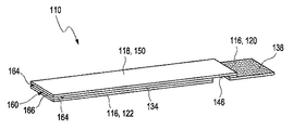
検査エレメントは、第1の電極および第2の電極を、さらなるデバイス、特に計量器と接触させるように構成された第1の電極接触域と第2の電極接触域とを備え得る。一実施形態では、第1の電極接触域および第2の電極接触域は、検査エレメントの同じ側から電気的に接触されるように構成され得る。第1の電極接触域および第2の電極接触域は、検査エレメントの層機構の異なる層内に配列され得、第1の電極接触域および第2の電極接触域の一方は、第1の電極接触域および第2の電極接触域の他方の電極接触域の上に突き出し得る。第1の電極接触域および第2の電極接触域は、層機構の階段構成の異なる段を形成し得る。たとえば、第1の電極接触域および第2の電極接触域は、検査エレメントの一端における2つの方形域であってよい。第1の電極接触域および第2の電極接触域は各々、さらなるデバイスの少なくとも1つのコネクタ、たとえば計量器コネクタピンによって当たられ得る。さらなるデバイスは、2対のコネクタ、すなわち、第1の電極および第2の電極の各々に対して1対を持ち得る。各コネクタ対の1つのコネクタは、検査エレメントを通る電流の流れを支持するように構成され得る。他のコネクタは、電圧を検出するために使用され得る。4ワイヤ技法(4−wire−technique)とも呼ばれるそのような構成によって、さらなるデバイスの電子コントローラが、第1の電極および第2の電極接触域とコネクタとの接続スポットにおいて寄生輸送抵抗によって誘発される電圧低下を補償することが可能になり得る。しかしながら、以下で詳細に概説されるように、第1の電極および第2の電極は対向する電極として構成され得るので、検査エレメントの同じ側からの電気接触を可能にするために、第1の電極または第2の電極は、少なくとも1つの導電性ターンオーバエレメントによって電気的に接触され得る。 The inspection element may include a first electrode contact area and a second electrode contact area configured to bring the first and second electrodes into contact with additional devices, particularly measuring instruments. In one embodiment, the first electrode contact area and the second electrode contact area may be configured to be electrically contacted from the same side of the inspection element. The first electrode contact area and the second electrode contact area can be arranged in different layers of the layer mechanism of the inspection element, and one of the first electrode contact area and the second electrode contact area is the first electrode. It may project above the contact area and the other electrode contact area of the second electrode contact area. The first electrode contact area and the second electrode contact area can form different steps of the staircase structure of the layer mechanism. For example, the first electrode contact area and the second electrode contact area may be two square areas at one end of the inspection element. The first electrode contact area and the second electrode contact area can each be hit by at least one connector on the additional device, such as a measuring instrument connector pin. Further devices may have two pairs of connectors, one pair for each of the first and second electrodes. One connector for each connector pair may be configured to support the flow of current through the inspection element. Other connectors can be used to detect the voltage. With such a configuration, also called the 4-wire technique (4-wire-technique), the electronic controller of the additional device is induced by parasitic transport resistance at the connection spot between the first electrode and the second electrode contact area and the connector. It may be possible to compensate for the voltage drop. However, as outlined in detail below, the first and second electrodes can be configured as opposing electrodes so that the first electrode can be electrically contacted from the same side of the inspection element. The electrode or the second electrode can be electrically contacted by at least one conductive turnover element.
一実施形態では、第1の電極接触域および第2の電極接触域は、検査エレメントの両側から電気的に接触されるように構成され得る。第1の電極は、検査エレメント層機構から突き出す第1の電極接触域を通って接触され得る。カバー箔およびスペーサ箔を通るパン
チ孔は、第2の電極接触域、特にコンタクトホールとして構成され得る。したがって、上記で概説されたように、さらなる導電性ターンオーバエレメントが、同じ側の接点に関して必要とされ得ない。第1の電極接触域および第2の電極接触域は、さらなるデバイスの少なくとも1つのコネクタ、たとえば計量器コネクタピンによって当たられ得る。好ましくは、さらなるデバイスは、2対のコネクタ、すなわち、第1の電極および第2の電極の各々に対して1対を持ち得る。1対のコネクタは、検査エレメントの一方の側からの第1の電極または第2の電極の1つと接触し得るが、他の対は、検査エレメントの対向する側からの第1の電極または第2の電極の他方の電極と接触し得る。
In one embodiment, the first electrode contact area and the second electrode contact area may be configured to be in electrical contact from both sides of the inspection element. The first electrode may be contacted through a first electrode contact area protruding from the inspection element layer mechanism. The punch holes passing through the cover foil and the spacer foil can be configured as a second electrode contact area, particularly a contact hole. Therefore, as outlined above, no additional conductive turnover element may be required for contacts on the same side. The first electrode contact area and the second electrode contact area can be hit by at least one connector of the additional device, such as a measuring instrument connector pin. Preferably, the additional device may have two pairs of connectors, i.e. one pair for each of the first and second electrodes. A pair of connectors may contact one of the first or second electrodes from one side of the inspection element, while the other pair is the first electrode or first electrode from the opposite side of the inspection element. It can come into contact with the other electrode of the two electrodes.
第1の電極または第2の電極の一方または両方は、少なくとも1つの導電性ターンオーバエレメントによって電気的に接触され得、第1の電極または第2の電極はそれぞれ、第1の方向を向くように方向付けられてよく、導電性ターンオーバエレメントは第2の方向から接触可能であってよく、第2の方向は、第1の方向の対向する方向である。導電性ターンオーバエレメントは、第1のセクションと第2のセクションとを有する導電性層または導電性箔のうちの少なくとも1つを備え得、それぞれ、第1のセクションは、第1の電極または第2の電極と電気的に接触し、第2のセクションは電気的に接触可能である。たとえば、導電性ターンオーバエレメントは、導電性接着層として構成され得る。導電性ターンオーバエレメントは、それぞれ第1の電極または第2の電極を備える少なくとも1つの層によって部分的に被覆され得、第2のセクションは、被覆されていない領域内に設置され得る。本明細書で使用されるとき、「部分的に被覆された」という用語は、導電性ターンオーバエレメントの一部は、第1の電極または第2の電極を備える少なくとも1つの層によって被覆される場合があり、導電性ターンオーバエレメントの一部は被覆されない場合があることを指す。導電性ターンオーバエレメントは、それぞれ第1の電極または第2の電極まで積層され得る。 One or both of the first electrode or the second electrode may be electrically contacted by at least one conductive turnover element so that the first electrode or the second electrode each faces the first direction. The conductive turnover element may be accessible from a second direction, the second direction being the opposite direction of the first direction. The conductive turnover element may comprise at least one of a conductive layer or a conductive foil having a first section and a second section, each of which is a first electrode or a first section. It is in electrical contact with the second electrode and the second section is electrically accessible. For example, the conductive turnover element can be configured as a conductive adhesive layer. The conductive turnover element can be partially covered by at least one layer, each with a first electrode or a second electrode, and the second section can be placed within the uncoated area. As used herein, the term "partially coated" means that a portion of a conductive turnover element is coated by at least one layer with a first electrode or a second electrode. In some cases, it means that some of the conductive turnover elements may not be coated. The conductive turnover elements can be stacked up to the first electrode or the second electrode, respectively.
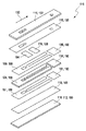
検査エレメントは層機構を備え得、第1の電極は、少なくとも1つの第1の電極キャリア層上に配置された少なくとも1つの第1の電極導電層を備え得、第2の電極は、少なくとも1つの第2の電極キャリア層上に配置された少なくとも1つの第2の電極導電層を備え得る。層機構は、第1の電極導電層が第2の電極導電層に面し、その間に毛細管を有するように配列され得る。少なくとも1つのスペーサ層が、第1の電極導電層と第2の電極導電層との間に配置され得る。さらに、層機構は、少なくとも1つの接着層を備え得る。電気化学セルの高さは、第1の電極と第2の電極との間のスペーサ層および接着層の厚さによって規定され得る。少なくとも1つの接着層がキャリアエレメントと第1の電極キャリア層との間に、および/または試薬コーティングとスペーサ層との間に配列され得る実施形態が実行可能である。たとえば、少なくとも1つの接着層がキャリアエレメントと第1の電極キャリア層との間に配列され得る場合、少なくとも1つの接着層は、キャリアエレメントと第1の電極との間の間隙が形成され得るように、電気化学セルの位置によって画定された領域が接着層によって被覆されないように位置決めされ得る。したがって、使用者が不注意で検査エレメントを曲げた場合、第1の電極表面と第2の電極表面との距離は、影響されないままであり得る。さらに、少なくとも1つの接着層は、カバー箔と第2の電極導電層および/または第2の電極導電層とスペーサ層との間に配列され得る導電性接着層、たとえば銀系接着剤であり得る。しかしながら、他の構成の接着層も実現可能であり得る。 The inspection element may include a layer mechanism, the first electrode may include at least one first electrode conductive layer disposed on at least one first electrode carrier layer, and the second electrode may include at least one. It may include at least one second electrode conductive layer disposed on one second electrode carrier layer. The layer mechanism can be arranged such that the first electrode conductive layer faces the second electrode conductive layer and has a capillary tube between them. At least one spacer layer may be arranged between the first electrode conductive layer and the second electrode conductive layer. In addition, the layer mechanism may include at least one adhesive layer. The height of the electrochemical cell can be defined by the thickness of the spacer layer and the adhesive layer between the first electrode and the second electrode. An embodiment in which at least one adhesive layer can be arranged between the carrier element and the first electrode carrier layer and / or between the reagent coating and the spacer layer is feasible. For example, if at least one adhesive layer can be arranged between the carrier element and the first electrode carrier layer, then at least one adhesive layer can form a gap between the carrier element and the first electrode. In addition, the area defined by the location of the electrochemical cell can be positioned so that it is not covered by the adhesive layer. Therefore, if the user inadvertently bends the inspection element, the distance between the first electrode surface and the second electrode surface may remain unaffected. Further, the at least one adhesive layer can be a conductive adhesive layer that can be arranged between the cover foil and the second electrode conductive layer and / or between the second electrode conductive layer and the spacer layer, for example a silver-based adhesive. .. However, adhesive layers of other configurations may also be feasible.
検査エレメントは、層機構を備え得る。作用電極は、少なくとも1つの第1の電極導電層を備え得る。第1の電極導電層は、カーボンインクコーティングを含み得る。第1の電極導電層は、少なくとも1つの第1の電極キャリア層上に配置され得る。第1の電極キャリア層は箔、たとえば上部箔であってよい。作用電極は、第1の電極導電層と接触する少なくとも1つの試薬コーティング、たとえば検出試薬コーティングを備え得る。試薬コーティングは、第1の電極導電層を少なくとも部分的に被覆し得る。対極は、少なくとも1
つの第2の電極導電層を備え得る。第2の電極導電層は、カーボンインクコーティングを含み得る。第2の電極導電層は、少なくとも1つの第2の電極キャリア層上に配置され得る。第2の電極キャリア層は箔、たとえば下部箔であってよい。対極は、第2の電極導電層と接触する少なくとも1つの試薬コーティングを備え得る。試薬コーティングは、酸化還元化学物質を含んでよい。試薬コーティングは、Ag/AgClインクを含み得る。試薬コーティングは、第2の電極導電層を少なくとも部分的に被覆し得る。作用電極および対極の試薬コーティングは、それぞれの電極導電層の等しいエリアを被覆し得る。少なくとも1つのスペーサ層が、第1の電極導電層と第2の電極導電層との間に配置され得る。接着層は、スペーサ層の一方または両方の側に適用され得る。したがって、第1の電極導電層および第2の電極導電層は、スペーサ層によって層機構内で固定され得る。第1の電極および第2の電極ならびに第1の電極と第2の電極との間の毛細管は、電気化学セルを形成する。電気化学セルは、毛細管の全長にわたって延び得る。第1の電極および第2の電極は、毛細管の全長にわたって延び得る。スペーサ層は、検査エレメントの全長にわたって延びないように配列され得る。たとえば、スペーサ層は、毛細管を一部被覆し得る。毛細管は、3つの側面で開いている。体液の試料は、側方投与位置および前面投与位置に適用可能であり得る。
The inspection element may include a layering mechanism. The working electrode may include at least one first electrode conductive layer. The first electrode conductive layer may include a carbon ink coating. The first electrode conductive layer may be arranged on at least one first electrode carrier layer. The first electrode carrier layer may be a foil, for example an upper foil. The working electrode may comprise at least one reagent coating that contacts the first electrode conductive layer, such as a detection reagent coating. The reagent coating can cover the first electrode conductive layer at least partially. The opposite pole is at least 1
It may include two second electrode conductive layers. The second electrode conductive layer may include a carbon ink coating. The second electrode conductive layer may be arranged on at least one second electrode carrier layer. The second electrode carrier layer may be a foil, for example a lower foil. The counter electrode may include at least one reagent coating that contacts the second electrode conductive layer. The reagent coating may include redox chemicals. The reagent coating may include Ag / AgCl ink. The reagent coating can cover the second electrode conductive layer at least partially. The working electrode and counter electrode reagent coatings may cover equal areas of the respective electrode conductive layers. At least one spacer layer may be arranged between the first electrode conductive layer and the second electrode conductive layer. The adhesive layer can be applied to one or both sides of the spacer layer. Therefore, the first electrode conductive layer and the second electrode conductive layer can be fixed in the layer mechanism by the spacer layer. The first and second electrodes and the capillaries between the first and second electrodes form an electrochemical cell. The electrochemical cell can extend over the entire length of the capillary. The first electrode and the second electrode can extend over the entire length of the capillary. The spacer layer may be arranged so as not to extend over the entire length of the inspection element. For example, the spacer layer may partially cover the capillaries. The capillaries are open on three sides. Bodily fluid samples may be applicable in lateral and anterior dosing positions.
さらに、検査エレメントは、作用電極および対極をさらなるデバイスと接触させるように構成された第1の電極接触域と第2の電極接触域とを備え得る。第1の電極接触域および/または第2の電極接触域ならびに側方投与位置および前面投与位置は、検査エレメントの両端に配列され得る。第1の電極接触域および第2の電極接触域は、検査エレメントの層機構の異なる層内に配列され得る。第1の電極接触域および第2の電極接触域は、たとえば検査エレメントの上側および下側に、検査エレメントの両側から電気的に接触されるように構成され得る。第1の電極導電層および第1の電極キャリア層は、第2の電極導電層および第2の電極キャリア層の上方で、検査エレメントの接触側でオーバーハングを形成し得る。したがって、第1の電極導電層の一部が露出され得、作用電極をさらなるデバイスと接触させることを可能にし得る。上記で説明されたように、スペーサ層は、検査エレメントの全長にわたって延びないように配列され得る。スペーサ層は、少なくとも1つの孔および/または少なくとも1つの凹部を備えてよく、この孔および/または凹部は、恣意的な形、たとえば円形または方形を持ってよい。スペーサ層は、一部分または複数の部分に形成されてよい。第2の電極接触域は、以下の形で形成され得る。すなわち、第1の電極導電層および第1の電極キャリア層は、少なくとも1つの孔および/または少なくとも1つの凹部を備えてよく、この孔および/または凹部は、恣意的な形、たとえば円形または方形を持ってよい。たとえば、第1の電極導電層および第1の電極キャリア層内の少なくとも1つの凹部は、切断および/またはパンチングによって形成され得る。スペーサ層は、検査エレメントの層機構内で、スペーサ層が第1の電極導電層および第1の電極キャリア層の少なくとも1つの孔および/または少なくとも1つの凹部を被覆しないことがあるように、配列され得る。たとえば、スペーサ層内の少なくとも1つの凹部は、切断および/またはパンチングによって形成され得る。したがって、第2の電極導電層の一部が露出され得、対極をさらなるデバイスと接触させることを可能にし得る。 In addition, the inspection element may include a first electrode contact area and a second electrode contact area configured to bring the working electrode and counter electrode into contact with additional devices. The first electrode contact area and / or the second electrode contact area and the lateral and anterior dosing positions can be arranged at both ends of the test element. The first electrode contact area and the second electrode contact area can be arranged in different layers of the layer mechanism of the inspection element. The first electrode contact area and the second electrode contact area may be configured to be in electrical contact with, for example, the upper and lower sides of the inspection element from both sides of the inspection element. The first electrode conductive layer and the first electrode carrier layer may form an overhang on the contact side of the inspection element above the second electrode conductive layer and the second electrode carrier layer. Therefore, a portion of the first electrode conductive layer may be exposed, allowing the working electrode to be brought into contact with additional devices. As described above, the spacer layers can be arranged so that they do not extend over the entire length of the inspection element. The spacer layer may comprise at least one hole and / or at least one recess, which hole and / or recess may have an arbitrary shape, such as a circle or a square. The spacer layer may be formed in one part or a plurality of parts. The second electrode contact area can be formed in the following form. That is, the first electrode conductive layer and the first electrode carrier layer may include at least one hole and / or at least one recess, which hole and / or recess may have an arbitrary shape, for example circular or square. You may have. For example, at least one recess in the first electrode conductive layer and the first electrode carrier layer can be formed by cutting and / or punching. The spacer layer is arranged so that the spacer layer may not cover at least one hole and / or at least one recess in the first electrode conductive layer and the first electrode carrier layer within the layer mechanism of the inspection element. Can be done. For example, at least one recess in the spacer layer can be formed by cutting and / or punching. Therefore, a portion of the second electrode conductive layer can be exposed, allowing the counter electrode to be brought into contact with additional devices.
本発明のさらなる一態様では、上記の実施形態のうちの1つまたは複数に開示されているまたは以下でさらに詳細に開示される、検査エレメントを生産するための方法が開示される。この方法は、層機構を形成する少なくとも1つのステップを含む。第1の電極、第2の電極、および毛細管は、第1の電極および第2の電極が毛細管の両側に配列されるように形成される。可能な実施形態の説明および検査エレメントの定義については、本発明による上述の検査エレメントを参照可能である。 A further aspect of the invention discloses a method for producing an inspection element, which is disclosed in one or more of the above embodiments or in more detail below. This method involves at least one step of forming a layer mechanism. The first electrode, the second electrode, and the capillary are formed so that the first electrode and the second electrode are arranged on both sides of the capillary. The above-mentioned inspection elements according to the present invention can be referred to for a description of possible embodiments and definitions of inspection elements.
方法は、以下でさらに詳細に開示されている方法ステップを含み得る。この方法ステップは、一例として、所与の順序で実行され得る。しかしながら、異なる順序も実行可能で
ある。さらに、方法ステップの1つもしくは複数、またはすべてすら、並列に、または適時に重複するように、実行され得る。さらに、方法ステップの1つもしくは複数、またはすべてすら、1回、または繰り返し実行され得る。
The method may include method steps disclosed in more detail below. This method step can, by way of example, be performed in a given order. However, different orders are also feasible. In addition, one or more of the method steps, or even all, may be performed in parallel or in a timely manner. Moreover, one or more or even all of the method steps can be performed once or repeatedly.
特定の一実施形態では、検査エレメントは、検査ストリップ、たとえばストリップ形状を有する検査エレメント、特に方形ベースエリアであってよい。
検査エレメントは、連続プロセスにおいて生産され得る。本明細書で使用されるとき、「連続プロセス」という用語は、バッチツーバッチプロセスとは対照的に、生産が連続して、支持テープたとえばキャリアテープの中断なしに続行する恣意的なプロセスを指す。連続プロセスは、リールツーリールプロセスであってよい。たとえば、支持テープは、開始ローラから提供されてよく、その上にさらなるテープを積層した後、さらなるローラ上に巻き取られ得る。
In one particular embodiment, the inspection element may be an inspection strip, eg, an inspection element having a strip shape, particularly a square base area.
Inspection elements can be produced in a continuous process. As used herein, the term "continuous process" refers to an arbitrary process in which production continues without interruption of supporting tape, eg carrier tape, as opposed to batch-to-batch process. .. The continuous process may be a reel-to-reel process. For example, the support tape may be provided from the start roller, on which the additional tape may be laminated and then wound onto the additional roller.
層機構を形成するステップは、少なくとも1つの積層ステップを含んでよく、この積層ステップでは、少なくとも2つの層が積層プロセスによって結合される。積層ステップは、少なくとも2つのテープの積層を含み得る。層機構は、キャリアエレメント、第1の電極、第2の電極、スペーサ層、少なくとも1つの接着層のうちの1つまたは複数などの、検査エレメントの上記で説明されたエレメントを含み得る。 The step of forming the layer mechanism may include at least one laminating step, in which at least two layers are joined by a laminating process. The laminating step may include laminating at least two tapes. The layering mechanism may include the elements described above of the inspection element, such as a carrier element, a first electrode, a second electrode, a spacer layer, and one or more of at least one adhesive layer.
方法は、層機構を検査ストリップに切断することをさらに含み得る。層機構はテープ形の層機構であってよく、テープ形の層機構の幅は、検査ストリップの長さを規定する。検査ストリップの長さは、細長い方向における検査ストリップの最大延長として理解され得る。積層されたテープの幅は、テープ伸張方向に垂直な次元における最大延長として理解され得、テープ伸張方向では、テープの延長は、好ましくは少なくとも3分の1、少なくとも10分の1、または少なくとも100分の1すら、テープ伸張方向に垂直な延長を越える。「切断」という用語は、別個の検査ストリップが個別に使用され得るように、積層されたテープを別個の検査ストリップに分割することとして理解され得る。層機構、たとえば積層されたテープは、いくつかの検査ストリップ、好ましくは10以上、より好ましくは20以上、および最も好ましくは50以上の検査ストリップを1つのテープから切断することを可能にする長さを有してよい。切断は、切断デバイスによって実行され得る。無端の非構造化テープから作製されるそのようなストリップ設計は、切断距離および積層テープ幅を変更することによってストリップの長さおよび幅が容易に適応可能であるので、有利なことがある。 The method may further include cutting the layer mechanism into inspection strips. The layer mechanism may be a tape-type layer mechanism, and the width of the tape-type layer mechanism defines the length of the inspection strip. The length of the test strip can be understood as the maximum extension of the test strip in the elongated direction. The width of the laminated tape can be understood as the maximum extension in the dimension perpendicular to the tape stretching direction, in which the tape stretching is preferably at least one-third, at least one-tenth, or at least 100. Even a fraction exceeds the extension perpendicular to the tape stretching direction. The term "cutting" can be understood as dividing the laminated tape into separate inspection strips so that separate inspection strips can be used individually. The layered mechanism, eg, laminated tape, is of a length that allows several inspection strips, preferably 10 or more, more preferably 20 or more, and most preferably 50 or more inspection strips to be cut from one tape. May have. The disconnect can be performed by the disconnect device. Such strip designs made from endless unstructured tape can be advantageous as the length and width of the strip can be easily adapted by varying the cutting distance and laminated tape width.
毛細管の形成は、少なくとも1つのスペーサから毛細管を切り取ることを含み得る。切断は、キスカットプロセスを含み得る。キスカットプロセスでは、切断輪郭ホイールが使用され得る。スペーサ、特に検査エレメントのスペーサ層を切断した後で形成するスペーサテープは、両側において、接着材および剥離ライナの一方または両方を用いて被覆され得る。スペーサは、2つの反対に回転するホイールの間の間隙を通過し得、1つのホイールは、輪郭が描かれた毛細管形状がスペーサへと切断され得るような切断輪郭ホイールである。ストリップ幅は、2つの切断毛細管構造の間の距離によって規定され得る。 The formation of capillaries can include cutting the capillaries from at least one spacer. The cutting may include a kiss cutting process. A cut contour wheel may be used in the kiss cut process. The spacer, especially the spacer tape formed after cutting the spacer layer of the inspection element, can be coated on both sides with one or both of an adhesive and a release liner. The spacer may pass through the gap between two oppositely rotating wheels, one wheel being a cut contour wheel such that the contoured capillary shape can be cut into spacers. The strip width can be defined by the distance between the two cut capillaries.
作用電極は少なくとも1つの試薬を備え得、方法は、少なくとも1つのキャリア層の上の試薬ストライプをコーティングすることを含み得る。コーティングは、ダイコーティングプロセスを含み得る。ダイコーティングは、試薬ストライプを、コーティングデバイスに続いて乾燥器に通すことをさらに含み得る。 The working electrode may comprise at least one reagent and the method may include coating reagent stripes on at least one carrier layer. The coating may include a die coating process. Die coating may further include passing the reagent stripe through a dryer following the coating device.
支持テープ、たとえばキャリア層は、特にポリマー箔として、設けられ得る。キャリア層の上に、第1の電極キャリア層が積層される。第1の電極キャリア層は、導電層でコーティングされ得る。第1の電極キャリア層は、コーティングされた電極キャリア層および
支持テープを積層するとき、ストリップハンドルが形成され得るように、支持テープの幅よりも狭い幅を持ち得る。スペーサ層は、コーティングされた第1の電極キャリア層上に積層され得る。スペーサ層は、コーティングされた第1の電極キャリア層よりも狭い幅を持ち得る。スペーサ層は、コーティングされた第1の電極キャリア層の両縁で、一部がスペーサ層から被覆されず、電極接触域を形成するように、コーティングされた第1の電極キャリア層上に積層され得る。スペーサ層は、導電性材料でコーティングされてよく、好ましくは、薄い銀層でスパッタリングされ得る。第1の電極接触域および第2の電極接触域が被覆されないことがあるように、スペーサ層の上に、導電性接着層が積層され得る。導電性接着層の上に、第2の電極キャリア層は積層されてよく、薄い銀層でコーティングされてよく、Ag/AgClペーストのストライプによってコーティングされてよい。ストライプは、第1の電極試薬層に面するように位置決めされ得る。最後に、層機構は、毛細管が3つの側面で開いているように切断され得る。
Support tapes, such as carrier layers, can be provided, especially as polymeric foils. The first electrode carrier layer is laminated on the carrier layer. The first electrode carrier layer can be coated with a conductive layer. The first electrode carrier layer may have a width narrower than the width of the support tape so that a strip handle can be formed when the coated electrode carrier layer and the support tape are laminated. The spacer layer may be laminated on the coated first electrode carrier layer. The spacer layer may have a narrower width than the coated first electrode carrier layer. The spacer layer is laminated on the coated first electrode carrier layer at both edges of the coated first electrode carrier layer so as to form an electrode contact area without being partially covered with the spacer layer. obtain. The spacer layer may be coated with a conductive material and may preferably be sputtered with a thin silver layer. A conductive adhesive layer may be laminated on the spacer layer so that the first electrode contact area and the second electrode contact area may not be covered. A second electrode carrier layer may be laminated on top of the conductive adhesive layer, coated with a thin silver layer, or coated with stripes of Ag / AgCl paste. The stripes can be positioned to face the first electrode reagent layer. Finally, the layer mechanism can be cut so that the capillaries are open on three sides.
さらに、方法は、孔、たとえば上部投与位置のための孔、コンタクトホール、通気孔開口を検査エレメント内に作製することを含み得る。一般に、孔は、恣意的な形状、たとえば方形形状または丸い形状を持ってよい。 In addition, the method may include creating holes, such as holes for upper dosing positions, contact holes, vent openings within the test element. In general, the holes may have an arbitrary shape, such as a square or round shape.
さらなる一態様では、試料の少なくとも1つの性質を判定するためのシステムが開示される。このシステムは、上記の実施形態のうちの1つまたは複数に開示されているまたは以下でさらに詳細に開示される、少なくとも1つの検査エレメントを備える。システムは、検査エレメントを使用して少なくとも1つの電気測定を実行するために適合された少なくとも1つの測定デバイスをさらに備える。可能な実施形態の説明および検査エレメントの定義については、本発明による上述の検査エレメントを参照可能である。 In a further aspect, a system for determining at least one property of a sample is disclosed. The system comprises at least one inspection element disclosed in one or more of the above embodiments or disclosed in more detail below. The system further comprises at least one measuring device adapted to perform at least one electrical measurement using the inspection element. The above-mentioned inspection elements according to the present invention can be referred to for a description of possible embodiments and definitions of inspection elements.
本明細書で使用されるとき、「少なくとも1つの性質を判定する」という用語は、体液中の少なくとも1つの分析物を検出することを指す。しかしながら、他の性質が検出され得る実施形態も実行可能である。本明細書で使用されるとき、「測定デバイス」という用語は、検査エレメントとは独立して扱われ得る恣意的なデバイス、好ましくは電子デバイスを指す。測定デバイスは、第1の電極および第2の電極の一方によって生成された少なくとも1つの信号を検出し、第1の電極および第2の電極の他方の電極に電圧を印加するために検査エレメントと相互作用するように適合され得る。測定デバイスはさらに、この検出から、体液中の分析物の存在および/または濃度に関する情報の少なくとも1つの項目を得るように適合され得る。したがって、測定デバイスは、少なくとも1つの分析物の少なくとも1つの情報および/または濃度を少なくとも1つの信号から得るために、第1の電極および第2の電極と相互作用する少なくとも1つの電子評価デバイスを備え得る。したがって、測定デバイスは、マイクロコントローラなどの少なくとも1つのデータ処理デバイスを備える少なくとも1つの評価ユニットを備え得る。 As used herein, the term "determining at least one property" refers to detecting at least one analyte in a body fluid. However, embodiments in which other properties can be detected are also feasible. As used herein, the term "measuring device" refers to an arbitrary device, preferably an electronic device, that can be treated independently of the inspection element. The measuring device and the inspection element to detect at least one signal generated by one of the first electrode and the second electrode and apply a voltage to the other electrode of the first electrode and the second electrode. Can be adapted to interact. The measuring device may further be adapted from this detection to obtain at least one item of information regarding the presence and / or concentration of the analyte in the body fluid. Thus, the measuring device comprises at least one electronic evaluation device that interacts with a first electrode and a second electrode in order to obtain at least one information and / or concentration of at least one analyte from at least one signal. Can be prepared. Therefore, the measurement device may include at least one evaluation unit with at least one data processing device such as a microcontroller.
検査エレメントは、測定デバイスの検査エレメント容器に挿入され得る。本明細書で使用されるとき、検査エレメント容器は、少なくとも1つの検査エレメントを受け入れるように適合された機械的インタフェースであってよい。最も好ましくは、検査エレメント容器は、一度に1つの検査エレメントを正確に受け入れるように適合された検査エレメント容器である。機械的インタフェースは、検査エレメントを少なくとも部分的に受け入れ、測定中に検査エレメントを機械的に固着するように適合され得る。検査エレメント容器は、特に測定デバイスの少なくとも1つのコネクタエレメント、たとえば2対のコネクタピンとの第1の電極接触域および第2の電極接触域の接触を介して、第1の電極および第2の電極と電気的に接触するように構成され得る。 The inspection element can be inserted into the inspection element container of the measuring device. As used herein, the inspection element container may be a mechanical interface adapted to accept at least one inspection element. Most preferably, the inspection element container is an inspection element container adapted to receive exactly one inspection element at a time. The mechanical interface can be adapted to accept the inspection element at least partially and mechanically secure the inspection element during measurement. The inspection element container is the first electrode and the second electrode, especially through contact of at least one connector element of the measuring device, eg, a first electrode contact area and a second electrode contact area with two pairs of connector pins. Can be configured to make electrical contact with.
測定デバイスは、第1の電極および第2の電極を使用して少なくとも1つのインピーダンス測定を実行するように構成され得る。測定デバイスは、第1の電極および第2の電極
を使用して少なくとも1つの電流測定を実行するようにさらに構成され得る。
The measuring device may be configured to perform at least one impedance measurement using the first and second electrodes. The measuring device may be further configured to perform at least one current measurement using the first and second electrodes.
測定デバイスは、AC信号とDC信号の両方を検出するように構成され得る。測定デバイスは、AC信号およびDC信号を同時に検出するように構成され得る。AC信号とDC信号の両方の並行判定は、それぞれの励起電位を重ねることによって実行され得る。測定デバイスは、AC信号およびDC信号を順次検出するように構成され得る。2つの測定間の時間間隔は、時間に依存する影響を最小にするために、可能な限り短くてよい。測定デバイスは、第1の電極および第2の電極にAC信号を印加し、たとえば連続的に、応答を検出するように構成され得る。測定デバイスは、第1の電極と第2の電極との間にAC信号を印加し、応答を経時的に測定することによって、接触時間、たとえば試料が第1の電極表面および第2の電極表面と接触し得る時間を検出し得る。AC応答が、あらかじめ定義された閾値を超え得る場合、これは、「検出された試料投与」と認識され得る。 The measuring device may be configured to detect both AC and DC signals. The measuring device may be configured to detect AC and DC signals simultaneously. Parallel determination of both AC and DC signals can be performed by superimposing their respective excitation potentials. The measuring device may be configured to sequentially detect AC and DC signals. The time interval between the two measurements may be as short as possible to minimize time-dependent effects. The measuring device may be configured to apply an AC signal to the first and second electrodes and, for example, continuously detect a response. The measuring device applies an AC signal between the first electrode and the second electrode and measures the response over time so that the contact time, for example, the sample is on the surface of the first electrode and the surface of the second electrode. The time that can be in contact with can be detected. If the AC response can exceed a predefined threshold, this can be recognized as "detected sample administration".
測定デバイスは、電気化学セルの充填レベルとは無関係に少なくとも1つの分析物を検出するように構成される。同時ACおよびDC測定を実行することによって、検査エレメントの毛細管の完全な充填が必要でないことがある。AC信号は、毛細管の充填レベルに比例し得る。電気化学セルの電気伝導度Gは、毛細管の充填レベルに比例し得、以下のように定義される。 The measuring device is configured to detect at least one analyte regardless of the filling level of the electrochemical cell. By performing simultaneous AC and DC measurements, complete filling of the capillaries of the test element may not be required. The AC signal can be proportional to the filling level of the capillaries. The electrical conductivity G of the electrochemical cell can be proportional to the filling level of the capillaries and is defined as follows.
G=x・(l・w)/h
上式で、xは試料の比導電率、lは毛細管の充填長、wは毛細管の幅、hは毛細管の高さである。上記で説明されたように、電気化学セルの高さは、第1の電極と第2の電極との間のスペーサ層および接着層の厚さによって規定され得る。さらに上記で説明されたように、「毛細管の長さ」という用語は、検査エレメント内の1つの次元における毛細管の最大延長を指す。一実施形態では、毛細管は、この場合、毛細管の長さが、細長い検査エレメント方向に垂直な毛細管の最大延長を指すように、細長い検査エレメント方向に垂直に延び得る。一実施形態では、毛細管は、この場合、毛細管の長さが、細長い検査エレメント方向に沿った毛細管の最大延長を指すように、細長い検査エレメント方向に沿って延び得る。「毛細管の充填された長さ」という用語は、試料によって充填される毛細管長さ全体の量を指す。毛細管の「幅」という用語は、2次元空間では、毛細管の長さに垂直な次元における毛細管の最大延長を指す。
G = x · (l · w) / h
In the above equation, x is the specific conductivity of the sample, l is the filling length of the capillary, w is the width of the capillary, and h is the height of the capillary. As described above, the height of the electrochemical cell can be defined by the thickness of the spacer layer and the adhesive layer between the first electrode and the second electrode. Further, as explained above, the term "capillary length" refers to the maximum extension of a capillary in one dimension within the test element. In one embodiment, the capillaries may extend perpendicular to the elongated examination element, in this case such that the length of the capillary points to the maximum extension of the capillary perpendicular to the elongated examination element. In one embodiment, the capillary may extend along the elongated examination element direction, in this case such that the length of the capillary points to the maximum extension of the capillary along the elongated examination element direction. The term "filled length of capillaries" refers to the total amount of capillaries filled by the sample. The term "width" of a capillary refers in two-dimensional space to the maximum extension of the capillary in a dimension perpendicular to the length of the capillary.
電気化学セルの電流測定応答DCは、毛細管の充填レベルに比例し得、いわゆるコットレル関数
DC=(l・w)・c・F・z・D1/2・t−1/2
によって定義され、上式で、Fはファラデー定数、cは分析物の初期濃度、zは遷移電子の数、Dは拡散係数、tは測定時間である。
The current measurement response DC of the electrochemical cell can be proportional to the filling level of the capillaries, the so-called Cottrell function DC = (l · w) · c · F · z · D 1/2 · t- 1 / 2
In the above equation, F is the Faraday constant, c is the initial concentration of the analyte, z is the number of transition electrons, D is the diffusion coefficient, and t is the measurement time.
電気伝導度と電流測定応答の両方は、一般的に、AC測定値およびDC測定値の関係たとえば比が充填レベルとは無関係であるように、毛細管の充填レベルに比例する。充填レベルの変動および/または充填レベルによる影響は、較正によって補償され得る。したがって、同時ACおよびDC測定を実行することによって、検査エレメントは、追加投与または充填検出電極なしに設計され得る。 Both electrical conductivity and current measurement response are generally proportional to the filling level of the capillary so that the relationship between the AC and DC measurements, eg, the ratio, is independent of the filling level. Fluctuations in filling levels and / or the effects of filling levels can be compensated for by calibration. Therefore, by performing simultaneous AC and DC measurements, the test element can be designed without additional dosing or filling detection electrodes.
測定デバイスは、毛細管の充填プロセスを電気的にモニタするようにさらに構成され得る。たとえば、毛細管が検査エレメントの長手方向軸に沿って少なくとも部分的に延び得る一実施形態では、測定デバイスは、試料がいつ作用電極の試薬コーティングに到達し得るかを電気的にモニタするように構成され得る。試薬コーティングは、第1の電極表面において酸化または還元され得る少なくとも1つの酸化還元活性物質を含み得る。測定デバイスは、第1の電極と第2の電極との間にDC電圧を印加し、応答、特にDC応答を検出
するように構成され得る。試料は試薬を溶解し始め、DC電圧が印加された場合、DC応答、特に応答信号が増加し得る。DC応答が、あらかじめ定義された閾値を超え得る場合、これは、「開始された分析物検出」と認識され得る。試薬コーティングに到達するための時間が、あらかじめ定義された限度を超え得る場合、エラーメッセージが測定デバイスによって生成され得る。
The measuring device may be further configured to electrically monitor the capillary filling process. For example, in one embodiment where the capillaries can extend at least partially along the longitudinal axis of the test element, the measuring device is configured to electrically monitor when the sample can reach the reagent coating on the working electrode. Can be done. The reagent coating may contain at least one redox active substance that can be oxidized or reduced on the surface of the first electrode. The measuring device may be configured to apply a DC voltage between the first electrode and the second electrode to detect a response, in particular a DC response. The sample begins to dissolve the reagents and the DC response, especially the response signal, can increase when a DC voltage is applied. If the DC response can exceed a predefined threshold, this can be recognized as "initiated analyte detection". If the time to reach the reagent coating can exceed a predefined limit, an error message can be generated by the measuring device.
さらに、測定デバイスは、毛細管がいつ完全に充填され得るかを電気的にモニタするように構成され得る。したがって、「検出された試料投与」および/または「開始された分析物検出」が検出された後、第2のAC電圧が電極に印加され得、応答が検出され得る。検出された応答信号が定常状態に到達する場合、これは、充填されたと認識され得る。充填のための時間が、あらかじめ定義された限度を超え得る場合、エラーメッセージが測定デバイスによって生成され得る。応答信号の勾配が測定され得る。勾配が、あらかじめ定義された閾値に達したまたはこれを超えた場合、これは、充填されたと認識され得る。あらかじめ定義された閾値は、最小充填レベルが保証されるように選定され得る。あらかじめ定義された閾値は、試料の比導電率に関して選定され得る。あらかじめ定義された閾値は、最低予想比導電率を有する試料に関して選定され得る。追加のあらかじめ定義された閾値は、充填レベルが判定および監視可能であるように、応答信号の勾配の異なる値に割り当てられ得る。 In addition, the measuring device may be configured to electrically monitor when the capillaries can be fully filled. Therefore, after the "detected sample administration" and / or "initiated analyte detection" is detected, a second AC voltage can be applied to the electrodes and a response can be detected. If the detected response signal reaches steady state, it can be recognized as filled. If the time for filling can exceed a predefined limit, an error message can be generated by the measuring device. The gradient of the response signal can be measured. If the gradient reaches or exceeds a predefined threshold, it can be recognized as filled. Predefined thresholds can be chosen to ensure a minimum filling level. A predefined threshold can be selected with respect to the specific conductivity of the sample. A predefined threshold can be selected for the sample with the lowest expected conductivity. Additional predefined thresholds can be assigned to different values of the gradient of the response signal so that the filling level can be determined and monitored.
測定デバイスは、体液の試料を加える前に少なくとも1つの初期フェイルセーフ測定を実行するように構成され得る。フェイルセーフ測定は、第1の電極および第2の電極を使用する少なくとも1つの電気測定を含み得る。電気測定は、少なくとも1つの電気測定値を得るために使用されてよく、フェイルセーフ測定は、電気測定値を少なくとも1つの閾値と比較することをさらに含み得る。フェイルセーフ測定は、第1の電極または第2の電極の少なくとも1つの少なくとも1つの損傷および/または劣化を検出することを含み得る。 The measuring device may be configured to perform at least one initial fail-safe measurement prior to adding a sample of body fluid. The fail-safe measurement may include at least one electrical measurement using a first electrode and a second electrode. Electrical measurements may be used to obtain at least one electrical measurement, and fail-safe measurements may further include comparing the electrical measurement to at least one threshold. Fail-safe measurements may include detecting at least one damage and / or deterioration of at least one of the first or second electrodes.
さらなる一態様では、試料の少なくとも1つの性質を判定するための方法が開示される。上記で概説されたように、「少なくとも1つの性質を判定する」という用語は、体液中の少なくとも1つの分析物を検出することを指す。定義および実施形態に関しては、検査エレメント、測定デバイス、および上記で開示された検査エレメントを生産するための方法の定義および実施形態を参照可能である。方法では、試料の少なくとも1つの性質を判定するためのシステムが使用される。システムの定義および実施形態に関しては、本発明による上述のシステムを参照可能である。方法は、以下のステップを含む。
a)検査エレメントを少なくとも1つの測定デバイスに接続するステップ
b)体液の試料を少なくとも1つの検査エレメントの毛細管に加えるステップ
c)AC信号とDC信号の両方を判定するステップ
d)AC信号およびDC信号を使用することによって測定結果を較正するステップ
この方法ステップは、一例として、所与の順序で実行され得る。しかしながら、異なる順序も実行可能である。さらに、方法ステップの1つもしくは複数、またはすべてすら、並列に、または適時に重複するように、実行され得る。さらに、方法ステップの1つもしくは複数、またはすべてすら、1回、または繰り返し実行され得る。検査エレメント、毛細管、および測定デバイスの定義および実施形態に関しては、上記で与えられた検査エレメント、毛細管、および測定システムの定義および実施形態を参照可能である。
In a further aspect, a method for determining at least one property of a sample is disclosed. As outlined above, the term "determining at least one property" refers to detecting at least one analyte in body fluids. For definitions and embodiments, the definitions and embodiments of inspection elements, measuring devices, and methods for producing the inspection elements disclosed above can be referenced. The method uses a system for determining at least one property of the sample. For the definition and embodiment of the system, the above-mentioned system according to the present invention can be referred to. The method includes the following steps:
a) Connecting the test element to at least one measuring device b) Adding a sample of body fluid to the capillary of at least one test element c) Determining both AC and DC signals d) AC and DC signals Steps to calibrate measurement results by using. This method step can be performed, for example, in a given order. However, different orders are also feasible. In addition, one or more of the method steps, or even all, may be performed in parallel or in a timely manner. Moreover, one or more or even all of the method steps can be performed once or repeatedly. For definitions and embodiments of test elements, capillaries, and measuring devices, the definitions and embodiments of test elements, capillaries, and measuring systems given above can be referenced.
ステップa)では、体液の試料が、少なくとも1つの検査エレメントの毛細管に加えられる。本明細書で使用されるとき、「加える」という用語は、毛細管の充填が可能であるように試料を検査エレメントに接触させるプロセスと、毛細管を充填するプロセスを指す。体液の試料は、側方投与位置、上部投与位置、前面投与位置の1つまたは複数に適用可能であり得る。試料は、側方投与位置によって検査エレメントに加えられ得、たとえば、指刺しからの毛細管血は、指を側方投与位置に押すことによって、側方投与位置に加えられ得る。体液の試料は、たとえば輸送デバイス、たとえばピペットによって、上方から検査エレメントの層機構を通って毛細管へと加えられ得る。試料は、前面投与位置によって検査エレメントに加えられ得る。 In step a), a sample of body fluid is added to the capillaries of at least one test element. As used herein, the term "add" refers to the process of bringing the sample into contact with the test element so that the capillaries can be filled, and the process of filling the capillaries. Bodily fluid samples may be applicable to one or more of the lateral, upper, and anterior dosing positions. The sample can be added to the test element by the lateral dosing position, for example, capillary blood from a finger stab can be added to the lateral dosing position by pushing the finger into the lateral dosing position. A sample of body fluid can be added from above through the layering mechanism of the test element into the capillaries, for example by a transport device, such as a pipette. The sample can be added to the test element depending on the anterior dosing position.
本明細書で使用されるとき、「少なくとも1つの測定デバイスに検査エレメントを接続する」という用語は、測定デバイスの検査エレメント容器、たとえば機械的インタフェースに検査エレメントを挿入し、特に測定デバイスの少なくとも1つのコネクタエレメントたとえば2対のコネクタピンとの第1の電極接触域および第2の電極接触域の接触を介して、第1の電極および第2の電極と電気的に接触することを指す。 As used herein, the term "connecting an inspection element to at least one measuring device" means inserting the inspection element into the inspection element container of the measuring device, eg, a mechanical interface, and in particular at least one of the measuring devices. One connector element refers to electrical contact with a first electrode and a second electrode through contact of a first electrode contact area and a second electrode contact area with, for example, two pairs of connector pins.
試料の少なくとも1つの性質、たとえば体液中のグルコースの濃度の安定した電流測定のために、測定が開始する前に毛細管が完全に充填されることが必要な場合がある。原理上、毛細管の充填は、投与または充填検出電極などの追加電極によって判定され得る。追加電極の使用を放棄することによって、検査エレメントの製造コストおよび材料コストが減少され得る。開示される方法は、追加電極を使用することのない毛細管充填の効果および/または影響なしに試料の少なくとも1つの性質を判定することを許可する。特に、毛細管の完全充填が必要でないことがある。ステップc)では、AC信号とDC信号の両方が判定される。本明細書で使用されるとき、「AC信号とDC信号の両方を判定する」という用語は、AC励起およびDC励起の両方、たとえば並列ACおよびDC励起と、AC応答信号とDC応答信号の両方の検出を指す。AC応答信号は、電気化学セルの電気伝導度であってもよいし、または電気伝導度に比例してもよい。AC信号およびDC信号は、同時に判定されてもよいし、または順次判定されてもよい。AC信号およびDC信号の判定は、励起電位を重ねることによって実行され得る。 For a stable current measurement of at least one property of the sample, eg, the concentration of glucose in the body fluid, it may be necessary for the capillaries to be completely filled before the measurement begins. In principle, capillary filling can be determined by additional electrodes such as dosing or filling detection electrodes. By abandoning the use of additional electrodes, the manufacturing and material costs of the inspection element can be reduced. The disclosed methods allow the determination of at least one property of the sample without the effect and / or effect of capillary filling without the use of additional electrodes. In particular, complete filling of capillaries may not be necessary. In step c), both the AC signal and the DC signal are determined. As used herein, the term "determining both AC and DC signals" refers to both AC and DC excitation, such as parallel AC and DC excitation, and both AC and DC response signals. Refers to the detection of. The AC response signal may be the electrical conductivity of the electrochemical cell or may be proportional to the electrical conductivity. The AC signal and the DC signal may be determined at the same time, or may be determined sequentially. The determination of the AC and DC signals can be performed by superimposing the excitation potentials.
ステップd)では、測定結果が、AC信号およびDC信号を使用することによって較正される。本明細書で使用されるとき、「較正」という用語は、AC応答信号および/またはDC応答信号に対する毛細管の充填レベルの影響および/または衝撃を減少させる、好ましくはなくすことを指す。AC信号とDC信号の両方は、毛細管の充填による影響が補償されるように、毛細管の充填レベルに比例し得る。AC応答信号は、電気化学セルの電気伝導度であってもよいし、または電気伝導度に比例してもよい。電気化学セルの電気伝導度Gは、毛細管の充填レベルに比例し得、以下のように定義される。 In step d), the measurement result is calibrated by using AC and DC signals. As used herein, the term "calibration" refers to reducing, preferably eliminating, the effect and / or impact of capillary filling levels on AC and / or DC response signals. Both the AC and DC signals can be proportional to the filling level of the capillaries so that the effects of filling the capillaries are compensated. The AC response signal may be the electrical conductivity of the electrochemical cell or may be proportional to the electrical conductivity. The electrical conductivity G of the electrochemical cell can be proportional to the filling level of the capillaries and is defined as follows.
G=x・(l・w)/h
上式で、xは試料の比導電率、lは毛細管の充填長、wは毛細管の幅、hは毛細管の高さである。DC応答信号は、いわゆるコットレル関数
DC=(l・w)・c・F・z・D1/2・t−1/2
によって定義される電気化学セルの電流測定応答DCであってもよいし、または電流測定応答DCに比例してもよく、上式で、Fはファラデー定数、cは分析物の初期濃度、zは遷移電子の数、Dは拡散係数、tは測定時間である。したがって、AC応答信号とDC応答信号の両方は、毛細管の充填された長さに比例し得る。AC信号およびDC信号を同時に測定することによって、充填レベルを変化させることによる影響が補償され得る。電気伝導度Gの判定された値と電流測定応答DCの判定された値が組み合わされ得る。毛細管の充填レベルを変化させることによる影響は、適切な較正による補償であり得る。たとえば、電気伝導度Gと電流測定応答の比が使用され得る。したがって、分数は、毛細管の充填された長さによって減少され得る。したがって、方法、具体的には方法ステップd)は、GとDC応答信号の比および/またはAC応答信号とDC応答信号の比などの比を形成することを含んでよく、この比は、たとえば一定の温度条件および他の測定条件の下で、充填長lとは無関係である、すなわち、電気化学セルの充填レベルとは無関係である。
G = x · (l · w) / h
In the above equation, x is the specific conductivity of the sample, l is the filling length of the capillary, w is the width of the capillary, and h is the height of the capillary. The DC response signal is the so-called Cottrell function DC = (l ・ w) ・ c ・ F ・ z ・ D 1/2・ t- 1 / 2
It may be the current measurement response DC of the electrochemical cell defined by, or it may be proportional to the current measurement response DC, where F is the Faraday constant, c is the initial concentration of the analyte, and z is. The number of transition electrons, D is the diffusion coefficient, and t is the measurement time. Therefore, both the AC and DC response signals can be proportional to the filled length of the capillaries. Simultaneous measurement of AC and DC signals can compensate for the effects of varying filling levels. The determined value of the electrical conductivity G and the determined value of the current measurement response DC can be combined. The effect of changing the filling level of the capillaries can be compensated by proper calibration. For example, the ratio of electrical conductivity G to current measurement response can be used. Therefore, the fraction can be reduced by the filled length of the capillaries. Thus, the method, specifically method step d), may include forming a ratio such as the ratio of the G to DC response signal and / or the ratio of the AC response signal to the DC response signal, which ratio is eg Under constant temperature and other measurement conditions, it is independent of the filling length l, i.e., independent of the filling level of the electrochemical cell.
方法は、接触時間を判定することをさらに含んでよく、AC信号は、検査エレメントの少なくとも1つの第1の電極と少なくとも1つの第2の電極との間に印加され得る。経時的な応答が測定され得、たとえば、AC応答信号が検出され得る。本明細書で使用されるとき、「接触時間」という用語は、試料が第1の電極表面および第2の電極表面と接触し得る時間を指す。AC応答は、あらかじめ定義された閾値と比較され得る。AC応答が、あらかじめ定義された閾値を超え得る場合、これは、「検出された試料投与」と認識され得る。 The method may further include determining the contact time, the AC signal may be applied between at least one first electrode and at least one second electrode of the inspection element. The response over time can be measured, for example an AC response signal can be detected. As used herein, the term "contact time" refers to the amount of time a sample can be in contact with the first and second electrode surfaces. The AC response can be compared to a predefined threshold. If the AC response can exceed a predefined threshold, this can be recognized as "detected sample administration".
方法は、毛細管の充填レベルを判定することをさらに含んでよく、AC信号は、検査エレメントの少なくとも1つの第1の電極と少なくとも1つの第2の電極との間に印加され得、経時的な応答信号が測定され得、応答が少なくとも1つの所定の閾値と比較され得る。本明細書で使用されるとき、「毛細管の充填レベルを判定する」という用語は、一般に、毛細管の充填に関する情報の少なくとも1つの項目を生成する恣意的なプロセスを指してよい。したがって、以下でさらに詳細に説明されるように、情報の少なくとも1つの項目は、一例として、充填レベルが少なくとも1つの所定のまたは判定可能な閾値を上回るかまたは下回るかに関する情報の項目を含み得る。しかしながら、追加または代替として、充填に関する情報の1つまたは複数の他の項目が判定され得る。 The method may further include determining the filling level of the capillaries, the AC signal can be applied between at least one first electrode and at least one second electrode of the inspection element over time. The response signal can be measured and the response can be compared to at least one predetermined threshold. As used herein, the term "determining the filling level of capillaries" may generally refer to an arbitrary process that produces at least one item of information regarding capillary filling. Thus, as described in more detail below, at least one item of information may include, by way of example, an item of information regarding whether the filling level is above or below at least one predetermined or determinable threshold. .. However, as an addition or alternative, one or more other items of information regarding filling may be determined.
たとえば、「検出された試料投与」および/または「開始された分析物検出」が検出された後、第2のAC電圧が電極に印加され得る。検出された応答信号が定常状態に到達する場合、これは、充填されたと認識され得る。充填のための時間が、あらかじめ定義された限度を超え得る場合、エラーメッセージが測定デバイスによって生成され得る。応答信号の勾配が測定され得る。勾配が、あらかじめ定義された閾値に達したまたはこれを超えた場合、これは、充填されたと認識され得る。あらかじめ定義された閾値は、最小充填レベルが保証されるように選定され得る。あらかじめ定義された閾値は、試料の比導電率に関して選定され得る。あらかじめ定義された閾値は、最低予想比導電率を有する試料に関して選定され得る。追加のあらかじめ定義された閾値は、充填レベルが判定および監視可能であるように、応答信号の勾配の異なる値に割り当てられ得る。 For example, a second AC voltage may be applied to the electrodes after "detected sample administration" and / or "initiated analyte detection" has been detected. If the detected response signal reaches steady state, it can be recognized as filled. If the time for filling can exceed a predefined limit, an error message can be generated by the measuring device. The gradient of the response signal can be measured. If the gradient reaches or exceeds a predefined threshold, it can be recognized as filled. Predefined thresholds can be chosen to ensure a minimum filling level. A predefined threshold can be selected with respect to the specific conductivity of the sample. A predefined threshold can be selected for the sample with the lowest expected conductivity. Additional predefined thresholds can be assigned to different values of the gradient of the response signal so that the filling level can be determined and monitored.
方法は、毛細管の充填プロセスをモニタすることをさらに含んでよく、DC電圧が、第1の電極と第2の電極との間に印加され得る。DC応答が検出され得る。DC応答は、あらかじめ定義された限度と比較され得る。試料が作用電極の試薬コーティングに到達すると、試薬コーティングは、少なくとも1つの酸化還元活性物質を含み得、第1の電極表面において酸化または還元され得る。DC電圧は第1の電極と第2の電極との間に印加され得、応答、特にDC応答が検出され得る。試料は試薬を溶解し始め、DC電圧が印加された場合、DC応答、特に応答信号が増加し得る。DC応答が、あらかじめ定義された閾値を超え得る場合、これは、「開始された分析物検出」と認識され得る。試薬コーティングに到達するための時間が、あらかじめ定義された限度を超え得る場合、エラーメッセージが測定デバイスによって生成され得る。 The method may further include monitoring the capillary filling process, where a DC voltage can be applied between the first and second electrodes. A DC response can be detected. The DC response can be compared to a predefined limit. When the sample reaches the reagent coating on the working electrode, the reagent coating may contain at least one redox active substance and may be oxidized or reduced on the surface of the first electrode. A DC voltage can be applied between the first electrode and the second electrode, and a response, especially a DC response, can be detected. The sample begins to dissolve the reagent and the DC response, especially the response signal, can increase when a DC voltage is applied. If the DC response can exceed a predefined threshold, this can be recognized as "initiated analyte detection". If the time to reach the reagent coating can exceed a predefined limit, an error message can be generated by the measuring device.
本発明の知見を要約すると、以下の実施形態が好ましい。
実施形態1:体液中の少なくとも1つの分析物を電気化学的に検出するための検査エレメントであって、少なくとも1つの第1の電極と少なくとも1つの第2の電極とを備え、第1の電極は作用電極として設計され、第2の電極は対極として設計され、検査エレメントは、体液の試料を受け入れることが可能な少なくとも1つの毛細管を備え、第1の電極および第2の電極が毛細管の両側に配列され、第1の電極および第2の電極ならびに第1の電極と第2の電極との間の毛細管が電気化学セルを形成し、検査エレメントは、電気化学セルの充填レベルとは無関係に少なくとも1つの分析物を検出するように構成され、第1の電極および第2の電極は、毛細管充填中に第1の電極および第2の電極が同時に、等しい速度で濡らされるように配列される、検査エレメント。
To summarize the findings of the present invention, the following embodiments are preferred.
Embodiment 1: An inspection element for electrochemically detecting at least one analyte in a body fluid, comprising at least one first electrode and at least one second electrode, the first electrode. Is designed as an working electrode, a second electrode is designed as a counter electrode, the test element comprises at least one capillary capable of receiving a sample of body fluid, and the first and second electrodes are on both sides of the capillary. The first electrode and the second electrode and the capillary tube between the first electrode and the second electrode form an electrochemical cell, and the inspection element is independent of the filling level of the electrochemical cell. It is configured to detect at least one analyte, the first and second electrodes are arranged such that the first and second electrodes are simultaneously wetted at equal rates during capillary filling. , Inspection element.
実施形態2:第1の電極が毛細管の全長にわたって延びる、先行する実施形態による検査エレメント。
実施形態3:第2の電極が毛細管の全長にわたって延びる、先行する実施形態のいずれか1つによる検査エレメント。
Embodiment 2: The inspection element according to the preceding embodiment, in which the first electrode extends over the entire length of the capillary.
Embodiment 3: An inspection element according to any one of the preceding embodiments, wherein the second electrode extends over the entire length of the capillary.
実施形態4:毛細管の充填された体積の増分dVあたりの第1の電極の濡らされた表面積dA1の増分は常に、第2の電極の濡らされた表面積dA2の増分に等しい、先行する実施形態のいずれか1つによる検査エレメント。 Embodiment 4: The increment of the wet surface area dA1 of the first electrode per increment dV of the filled volume of the capillary tube is always equal to the increment of the wet surface area dA2 of the second electrode, according to the preceding embodiment. Inspection element by any one.
実施形態5:毛細管の外側だが体液の試料を受け入れるための開口の隣に設置された検査エレメントの少なくとも1つの壁は、少なくとも1つの疎水性コーティングによって少なくとも部分的に被覆される、先行する実施形態のいずれか1つによる検査エレメント。 Embodiment 5: A preceding embodiment in which at least one wall of an inspection element located outside the capillary but next to an opening for receiving a sample of body fluid is at least partially covered with at least one hydrophobic coating. Inspection element by any one of.
実施形態6:電気化学セルが毛細管の全長にわたって延びる、先行する実施形態による検査エレメント。
実施形態7:第1の電極および第2の電極は非腐食性で非保護性の材料から作製される、先行する実施形態のいずれか1つによる検査エレメント。
Embodiment 6: Inspection element according to the preceding embodiment, in which the electrochemical cell extends over the entire length of the capillary.
Embodiment 7: An inspection element according to any one of the preceding embodiments, wherein the first electrode and the second electrode are made of a non-corrosive, non-protective material.
実施形態8:電気化学セルを形成する第1の電極の表面積および第2の電極の表面積は、同じ寸法を有する、先行する実施形態のいずれか1つによる検査エレメント。
実施形態9:第1の電極は、少なくとも1つの電極導電層と、第1の電極導電層と接触する少なくとも1つの試薬コーティングとを備える、先行する実施形態のいずれか1つによる検査エレメント。
Embodiment 8: An inspection element according to any one of the preceding embodiments, wherein the surface area of the first electrode and the surface area of the second electrode forming the electrochemical cell have the same dimensions.
Embodiment 9: An inspection element according to any one of the preceding embodiments, wherein the first electrode comprises at least one electrode conductive layer and at least one reagent coating in contact with the first electrode conductive layer.
実施形態10:第1の電極導電層は、金属層、好ましくはパラジウム、白金、銀、または金からなる群から選択された貴金属層と、導電性炭素層、特に炭素ペースト層のうちの少なくとも1つを含み得る、先行する実施形態による検査エレメント。 Embodiment 10: The first electrode conductive layer is a noble metal layer selected from the group consisting of a metal layer, preferably palladium, platinum, silver, or gold, and at least one of a conductive carbon layer, particularly a carbon paste layer. Inspection element according to the preceding embodiment, which may include one.
実施形態11:第1の電極導電層は、第1の電極キャリア層、好ましくは第1の電極キャリア箔上に配置される、2つの先行する実施形態のいずれか1つによる検査エレメント。 Embodiment 11: The inspection element according to any one of the two preceding embodiments, wherein the first electrode conductive layer is disposed on the first electrode carrier layer, preferably the first electrode carrier foil.
実施形態12:第1の電極導電層は、第1の電極キャリア層の第1の長手方向縁から第1の電極キャリア層の第2の長手方向縁に延び得る、先行する実施形態による検査エレメント。 Embodiment 12: The inspection element according to the preceding embodiment, wherein the first electrode conductive layer can extend from the first longitudinal edge of the first electrode carrier layer to the second longitudinal edge of the first electrode carrier layer. ..
実施形態13:第1の電極導電層は第1の電極キャリア層を完全に被覆する、先行する実施形態による検査エレメント。
実施形態14:試薬コーティングは第1の電極導電層上にコーティングされた少なくとも1つの試薬ストライプを含む、5つの先行する実施形態のいずれか1つによる検査エレメント。
Embodiment 13: The inspection element according to the preceding embodiment, wherein the first electrode conductive layer completely covers the first electrode carrier layer.
Embodiment 14: A test element according to any one of the five preceding embodiments, wherein the reagent coating comprises at least one reagent stripe coated on a first electrode conductive layer.
実施形態15:第2の電極は少なくとも1つの第2の電極導電層を備える、先行する実施形態のいずれか1つによる検査エレメント。
実施形態16:第2の電極導電層は、金属層、好ましくはパラジウム、銀、または金からなる群から選択された貴金属層と、導電性炭素層、特に炭素ペースト層のうちの少なくとも1つを含む、先行する実施形態による検査エレメント。
Embodiment 15: An inspection element according to any one of the preceding embodiments, wherein the second electrode comprises at least one second electrode conductive layer.
Embodiment 16: The second electrode conductive layer comprises a metal layer, preferably a noble metal layer selected from the group consisting of palladium, silver, or gold, and at least one of a conductive carbon layer, particularly a carbon paste layer. Inspection element according to the preceding embodiment, including.
実施形態17:第2の電極はAg/AgCl、特にAg/AgClペーストをさらに含
む、2つの先行する実施形態のいずれか1つによる検査エレメント。
実施形態18:第2の電極導電層は、第2の電極キャリア層、好ましくは第2の電極キャリア箔上に配置される、3つの先行する実施形態のいずれか1つによる検査エレメント。
Embodiment 17: A test element according to any one of two preceding embodiments, wherein the second electrode further comprises Ag / AgCl, in particular Ag / AgCl paste.
Embodiment 18: The inspection element according to any one of the three preceding embodiments, wherein the second electrode conductive layer is disposed on the second electrode carrier layer, preferably the second electrode carrier foil.
実施形態19:第2の電極導電層は、第2の電極キャリア層の第1の長手方向縁から第2の電極キャリア層の第2の長手方向縁に延びる、先行する実施形態による検査エレメント。 Embodiment 19: The inspection element according to the preceding embodiment, wherein the second electrode conductive layer extends from the first longitudinal edge of the second electrode carrier layer to the second longitudinal edge of the second electrode carrier layer.
実施形態20:第2の電極導電層は第2の電極キャリア層を完全に被覆する、先行する実施形態による検査エレメント。
実施形態21:検査エレメントは検査ストリップである、先行する実施形態のいずれか1つによる検査エレメント。
20: The inspection element according to the preceding embodiment, wherein the second electrode conductive layer completely covers the second electrode carrier layer.
Embodiment 21: The inspection element according to any one of the preceding embodiments, where the inspection element is an inspection strip.
実施形態22:毛細管が3つの側面で開いている、先行する実施形態のいずれか1つによる検査エレメント。
実施形態23:体液の試料は、側方投与位置、上部投与位置、前面投与位置のうちの1つまたは複数に適用可能である、先行する実施形態のいずれか1つによる検査エレメント。
Embodiment 22: An inspection element according to any one of the preceding embodiments, in which the capillaries are open on three sides.
Embodiment 23: A test element according to any one of the preceding embodiments, wherein the body fluid sample is applicable to one or more of a lateral administration position, an upper administration position, a frontal administration position.
実施形態24:検査エレメントは上部投与位置を備え、カバー箔を通って毛細管へと延びる、特に、毛細管の充填された体積の増分dVあたりの第1の電極の濡らされた表面積dA1の増分が常に第2の電極の濡らされた表面積dA2の増分に等しいという条件が依然として満たされるようにカバー箔を通って毛細管へと延びる貫通孔をさらに備える、先行する実施形態のいずれか1つによる検査エレメント。 Embodiment 24: The test element comprises an upper dosing position and extends through the cover foil to the capillary, in particular an increase in the wet surface area dA1 of the first electrode per increment dV of the filled volume of the capillary. An inspection element according to any one of the preceding embodiments, further comprising through-holes extending through the cover foil to the capillaries such that the condition equal to the increment of the wet surface area dA2 of the second electrode is still satisfied.
実施形態25:検査エレメントは、長手方向軸に沿って延びる細長い形状を有し、毛細管は少なくとも部分的に検査エレメントの長手方向軸に沿って延びる、先行する実施形態のいずれか1つによる検査エレメント。 Embodiment 25: The inspection element according to any one of the preceding embodiments, wherein the inspection element has an elongated shape extending along the longitudinal axis and the capillaries extend at least partially along the longitudinal axis of the inspection element. ..
実施形態26:検査エレメントは、長手方向軸に沿って延びる細長い形状を有し、毛細管は、少なくとも部分的に長手方向軸に垂直に延びる、先行する実施形態のいずれか1つによる検査エレメント。 Embodiment 26: The inspection element according to any one of the preceding embodiments, wherein the inspection element has an elongated shape extending along the longitudinal axis and the capillaries extend at least partially perpendicular to the longitudinal axis.
実施形態27:毛細管は、検査エレメントの第1の長手方向縁における第1の開口から検査エレメントの第2の長手方向縁における第2の開口に延びる、先行する実施形態による検査エレメント。 Embodiment 27: The capillary tube is an inspection element according to a preceding embodiment extending from a first opening at the first longitudinal edge of the inspection element to a second opening at the second longitudinal edge of the inspection element.
実施形態28:検査エレメントは、第1の開口または第2の開口の一方または両方に設置された側方投与位置を備える、先行する実施形態による検査エレメント。
実施形態29:毛細管は、検査エレメントの前面に開いた側部を有する、3つの先行する実施形態のいずれか1つによる検査エレメント。
Embodiment 28: The test element according to the preceding embodiment, wherein the test element comprises a lateral dosing position located in one or both of the first opening and the second opening.
Embodiment 29: The capillary is an inspection element according to any one of the three preceding embodiments having an open side portion in front of the inspection element.
実施形態30:検査エレメントは、検査エレメントの前面に設置された前面投与位置を有する、先行する実施形態による検査エレメント。
実施形態31:毛細管は通気孔開口を備える、先行する実施形態のいずれか1つによる検査エレメント。
Embodiment 30: The test element is a test element according to a preceding embodiment having a frontal administration position located in front of the test element.
Embodiment 31: The inspection element according to any one of the preceding embodiments, wherein the capillary comprises a vent opening.
実施形態32:検査エレメントはストリップハンドルを備える、先行する実施形態のいずれか1つによる検査エレメント。
実施形態33:検査エレメントは少なくとも1つのキャリアエレメントの上に配置された層機構を備え、キャリアエレメントは、検査エレメントの長手方向に、層機構から突き出し、それによって、ストリップハンドルを形成する、先行する実施形態による検査エレメント。
Embodiment 32: The inspection element according to any one of the preceding embodiments, comprising a strip handle.
Embodiment 33: The inspection element comprises a layer mechanism disposed on top of at least one carrier element, which precedes, projecting from the layer mechanism in the longitudinal direction of the inspection element, thereby forming a strip handle. Inspection element according to embodiment.
実施形態34:検査エレメントは、第1の電極および第2の電極をさらなるデバイス、特に計量器と接触させるように構成された第1の電極接触域と第2の電極接触域とを備える、先行する実施形態のいずれか1つによる検査エレメント。 Embodiment 34: The inspection element comprises a first electrode contact area and a second electrode contact area configured to contact the first electrode and the second electrode with an additional device, in particular a measuring instrument. Inspection element according to any one of the embodiments.
実施形態35:第1の電極接触域および第2の電極接触域は検査エレメントの同じ側から電気的に接触されるように構成される、先行する実施形態による検査エレメント。
実施形態36:第1の電極接触域および第2の電極接触域は、検査エレメントの層機構の異なる層内に配列され、第1の電極接触域および第2の電極接触域の一方は、第1の電極接触域および第2の電極接触域の他方の電極接触域の上に突き出す、先行する実施形態による検査エレメント。
Embodiment 35: The inspection element according to the preceding embodiment, wherein the first electrode contact area and the second electrode contact area are configured to be electrically contacted from the same side of the inspection element.
Embodiment 36: The first electrode contact area and the second electrode contact area are arranged in different layers of the layer mechanism of the inspection element, and one of the first electrode contact area and the second electrode contact area is the first. An inspection element according to a preceding embodiment that projects above one electrode contact area and the other electrode contact area of the second electrode contact area.
実施形態37:第1の電極接触域と第2の電極接触域は、層機構の階段構成の異なる段を形成する、先行する実施形態による検査エレメント。
実施形態38:第1の電極接触域および第2の電極接触域は、検査エレメントの両側から電気的に接触されるように構成される、4つの先行する実施形態のいずれか1つによる検査エレメント。
Embodiment 37: The inspection element according to the preceding embodiment, wherein the first electrode contact area and the second electrode contact area form different steps of the staircase structure of the layer mechanism.
Embodiment 38: The inspection element according to any one of the four preceding embodiments, wherein the first electrode contact area and the second electrode contact area are configured to be electrically contacted from both sides of the inspection element. ..
実施形態39:カバー箔およびスペーサ層を通るパンチ孔は、第2の電極接触域、特にコンタクトホールとして構成される、先行する実施形態による検査エレメント。
実施形態40:検査エレメントは少なくとも1つのキャリアエレメントを備える、先行する実施形態のいずれか1つによる検査エレメント。
Embodiment 39: The inspection element according to the preceding embodiment, wherein the punch hole through the cover foil and the spacer layer is configured as a second electrode contact area, particularly a contact hole.
Embodiment 40: The inspection element according to any one of the preceding embodiments, wherein the inspection element comprises at least one carrier element.
実施形態41:検査エレメントは層機構を備え、第1の電極は、少なくとも1つの第1の電極キャリア層上に配置された少なくとも1つの第1の電極導電層を備え、第2の電極は、少なくとも1つの第2の電極キャリア層上に配置された少なくとも1つの第2の電極導電層を備える、先行する実施形態のいずれか1つによる検査エレメント。 Embodiment 41: The inspection element comprises a layer mechanism, the first electrode comprises at least one first electrode conductive layer disposed on at least one first electrode carrier layer, and the second electrode comprises. An inspection element according to any one of the preceding embodiments, comprising at least one second electrode conductive layer disposed on at least one second electrode carrier layer.
実施形態42:層機構は、第1の電極導電層が第2の電極導電層に面し、その間に毛細管を有するように配列される、先行する実施形態による検査エレメント。
実施形態43:少なくとも1つのスペーサ層が第1の電極導電層と第2の電極導電層との間に配置される、2つの先行する実施形態のいずれか1つによる検査エレメント。
Embodiment 42: The layer mechanism is an inspection element according to a preceding embodiment in which the first electrode conductive layer is arranged so as to face the second electrode conductive layer and have a capillary tube between them.
Embodiment 43: An inspection element according to any one of two preceding embodiments, wherein at least one spacer layer is disposed between the first electrode conductive layer and the second electrode conductive layer.
実施形態44:第1の電極または第2の電極の一方または両方が少なくとも1つの導電性ターンオーバエレメントによって電気的に接触させられ、第1の電極または第2の電極はそれぞれ、第1の方向を向くように方向付けられ、導電性ターンオーバエレメントは第2の方向から接触可能であり、第2の方向は第1の方向の対向する方向である、先行する実施形態のいずれか1つによる検査エレメント。 Embodiment 44: One or both of the first electrode and the second electrode are electrically contacted by at least one conductive turnover element, and the first electrode or the second electrode is respectively in the first direction. The conductive turnover element is accessible from a second direction and the second direction is the opposite direction of the first direction, according to any one of the preceding embodiments. Inspection element.
実施形態45:導電性ターンオーバエレメントは、第1のセクションと第2のセクションとを有する導電性層または導電性箔のうちの少なくとも1つを備え、それぞれ、第1のセクションは、第1の電極または第2の電極と電気的に接触し、第2のセクションは電気的に接触可能である、先行する実施形態による検査エレメント。 Embodiment 45: The conductive turnover element comprises at least one of a conductive layer or a conductive foil having a first section and a second section, each of which is a first section. An inspection element according to a preceding embodiment that is in electrical contact with an electrode or a second electrode and the second section is electrically accessible.
実施形態46:導電性ターンオーバエレメントは、それぞれ第1の電極または第2の電極を備える少なくとも1つの層によって部分的に被覆され、第2のセクションは、被覆さ
れていない領域内に設置される、先行する実施形態による検査エレメント。
Embodiment 46: The conductive turnover element is partially covered by at least one layer, each with a first electrode or a second electrode, and the second section is placed within the uncoated area. , Inspection element according to the preceding embodiment.
実施形態47:導電性ターンオーバエレメントが第1の電極または第2の電極それぞれに積層される、2つの先行する実施形態のいずれか1つによる検査エレメント。
実施形態48:先行する実施形態による検査エレメントを生産するための方法であって、層機構を形成する少なくとも1つのステップを含み、第1の電極、第2の電極、および毛細管は、第1の電極および第2の電極が毛細管の両側に配列されるように形成される、方法。
Embodiment 47: An inspection element according to any one of two preceding embodiments, in which a conductive turnover element is laminated on each of a first electrode or a second electrode.
Embodiment 48: A method for producing an inspection element according to a preceding embodiment, comprising at least one step of forming a layered mechanism, the first electrode, the second electrode, and the capillary being the first. A method in which an electrode and a second electrode are formed so as to be arranged on both sides of a capillary.
実施形態49:検査エレメントは検査ストリップである、先行する実施形態による方法。
実施形態50:検査エレメントは、連続プロセスにおいて、好ましくはリールツーリールプロセスにおいて生産される、先行する方法実施形態のいずれか1つによる方法。
Embodiment 49: The method according to the preceding embodiment, wherein the inspection element is an inspection strip.
Embodiment 50: The inspection element is produced in a continuous process, preferably in a reel-to-reel process, according to any one of the preceding method embodiments.
実施形態51:層機構を形成するステップは少なくとも1つの積層ステップを含み、積層ステップでは、少なくとも2つの層が積層プロセスによって結合される、先行する方法実施形態のいずれか1つによる方法。 Embodiment 51: A method according to any one of the preceding method embodiments, wherein the step of forming the layer mechanism comprises at least one laminating step, in which at least two layers are joined by a laminating process.
実施形態52:積層ステップは少なくとも2つのテープの積層を含む、先行する実施形態による方法。
実施形態53:層機構を検査ストリップに切断することをさらに含む、先行する方法実施形態のいずれか1つによる方法。
Embodiment 52: The method according to the preceding embodiment, wherein the laminating step comprises laminating at least two tapes.
Embodiment 53: A method according to any one of the preceding method embodiments, further comprising cutting the layer mechanism into inspection strips.
実施形態54:層機構はテープ形の層機構であり、テープ形の層機構の幅は、検査ストリップの長さを規定する、先行する実施形態による方法。
実施形態55:毛細管の形成は、少なくとも1つのスペーサから毛細管を切り取ることを含む、先行する方法実施形態のいずれか1つによる方法。
Embodiment 54: The method according to the preceding embodiment, wherein the layer mechanism is a tape-type layer mechanism and the width of the tape-type layer mechanism defines the length of the inspection strip.
Embodiment 55: The method according to any one of the preceding method embodiments, wherein the formation of the capillaries comprises cutting the capillaries from at least one spacer.
実施形態56:切断はキスカットプロセスを含む、先行する実施形態による方法。
実施形態57:作用電極は少なくとも1つの試薬を備え、方法は、少なくとも1つのキャリア層の上の試薬ストライプをコーティングすることを含む、5つの先行する実施形態のいずれか1つによる方法。
Embodiment 56: The method according to the preceding embodiment, wherein the cutting comprises a kiss cut process.
Embodiment 57: The method according to any one of the five preceding embodiments, wherein the working electrode comprises at least one reagent and the method comprises coating a reagent stripe on at least one carrier layer.
実施形態58:コーティングはダイコーティングプロセスを含む、先行する実施形態による方法。
実施形態59:ダイコーティングは、試薬ストライプを、コーティングデバイスに続いて乾燥器に通すことをさらに含む、先行する実施形態による方法。
Embodiment 58: The method according to the preceding embodiment, wherein the coating comprises a die coating process.
Embodiment 59: The method according to the preceding embodiment, wherein the die coating further comprises passing the reagent stripe through a coating device followed by a dryer.
実施形態60:試料の少なくとも1つの性質を判定するためのシステムであって、検査エレメントに関する先行する実施形態のいずれか1つによる少なくとも1つの検査エレメントを備え、検査エレメントを使用して少なくとも1つの電気測定を実行するために適合された少なくとも1つの測定デバイスをさらに備える、システム。 Embodiment 60: A system for determining at least one property of a sample, comprising at least one inspection element according to any one of the preceding embodiments relating to the inspection element, and at least one using the inspection element. A system further comprising at least one measuring device adapted to perform electrical measurements.
実施形態61:検査エレメントは少なくとも1つの第1の電極と少なくとも1つの第2の電極とを備え、第1の電極は作用電極として設計され、第2の電極は対極として設計され、検査エレメントは、体液の試料を受け入れることが可能な少なくとも1つの毛細管を備え、第1の電極および第2の電極が毛細管の両側に配列され、第1の電極および第2の電極ならびに第1の電極と第2の電極との間の毛細管が電気化学セルを形成し、検査エレメントは、電気化学セルの充填レベルとは無関係に少なくとも1つの分析物を検出するように構成され、第1の電極および第2の電極は、毛細管充填中に第1の電極および第2の
電極が同時に、等しい速度で濡らされるように配列され、システムは、検査エレメントを使用して少なくとも1つの電気測定を実行するために適合された少なくとも1つの測定デバイスをさらに備え、測定デバイスは、AC信号とDC信号の両方を検出するように構成され、測定デバイスが、電気化学セルの充填レベルとは無関係に少なくとも1つの分析物を検出するように構成される、先行する実施形態によるシステム。
Embodiment 61: The inspection element comprises at least one first electrode and at least one second electrode, the first electrode is designed as an working electrode, the second electrode is designed as a counter electrode, and the inspection element is The first electrode and the second electrode are arranged on both sides of the capillary, and the first electrode and the second electrode and the first electrode and the first electrode are provided with at least one capillary capable of receiving a sample of body fluid. The capillary tube between the two electrodes forms an electrochemical cell, and the inspection element is configured to detect at least one analyte regardless of the filling level of the electrochemical cell, the first electrode and the second electrode. The electrodes are arranged so that the first and second electrodes are simultaneously wetted at equal rates during capillary filling, and the system is adapted to perform at least one electrical measurement using the inspection element. Further comprising at least one measuring device, the measuring device is configured to detect both an AC signal and a DC signal, and the measuring device performs at least one analysis object regardless of the filling level of the electrochemical cell. A system according to a preceding embodiment configured to detect.
実施形態62:測定デバイスは、第1の電極および第2の電極を使用して少なくとも1つのインピーダンス測定を実行するように構成される、システムに関する先行する実施形態のいずれか1つによるシステム。 Embodiment 62: A system according to any one of the preceding embodiments relating to the system, wherein the measuring device is configured to perform at least one impedance measurement using a first electrode and a second electrode.
実施形態63:測定デバイスは、第1の電極および第2の電極を使用して少なくとも1つの電流測定を実行するようにさらに構成される、2つの先行する実施形態のいずれか1つによるシステム。 Embodiment 63: A system according to any one of two preceding embodiments, wherein the measuring device is further configured to perform at least one current measurement using the first and second electrodes.
実施形態64:測定デバイスはAC信号とDC信号の両方を検出するように構成される、システムに関する先行する実施形態のいずれか1つによるシステム。
実施形態65:測定デバイスは、AC信号およびDC信号を順次検出するように構成される、先行する実施形態によるシステム。
Embodiment 64: A system according to any one of the preceding embodiments relating to the system, wherein the measuring device is configured to detect both AC and DC signals.
Embodiment 65: A system according to a preceding embodiment in which the measuring device is configured to sequentially detect AC and DC signals.
実施形態66:測定デバイスは、第1の電極および第2の電極にAC信号を印加し、応答を検出するように構成される、2つの先行する実施形態のいずれか1つによるシステム。 Embodiment 66: A system according to any one of two preceding embodiments, wherein the measuring device is configured to apply an AC signal to the first and second electrodes and detect a response.
実施形態67:測定デバイスは、毛細管の充填プロセスを電気的にモニタするようにさらに構成される、システムに関する先行する実施形態のいずれか1つによるシステム。
実施形態68:測定デバイスは、体液の試料を加える前に少なくとも1つの初期フェイルセーフ測定を実行するように構成される、システムに関する先行する実施形態のいずれか1つによるシステム。
Embodiment 67: A system according to any one of the preceding embodiments relating to the system, wherein the measuring device is further configured to electrically monitor the capillary filling process.
Embodiment 68: A system according to any one of the preceding embodiments relating to the system, wherein the measuring device is configured to perform at least one initial fail-safe measurement prior to adding a sample of body fluid.
実施形態69:フェイルセーフ測定は、第1の電極および第2の電極を使用する少なくとも1つの電気測定を含む、先行する実施形態によるシステム。
実施形態70:電気測定は、少なくとも1つの電気測定値を得るために使用され、フェイルセーフ測定は、電気測定値を少なくとも1つの閾値と比較することをさらに含む、先行する実施形態によるシステム。
Embodiment 69: The fail-safe measurement is a system according to a preceding embodiment that comprises at least one electrical measurement using a first electrode and a second electrode.
Embodiment 70: A system according to a preceding embodiment, wherein the electrical measurement is used to obtain at least one electrical measurement, and the fail-safe measurement further comprises comparing the electrical measurement with at least one threshold.
実施形態71:フェイルセーフ測定は、第1の電極または第2の電極の少なくとも1つの少なくとも1つの損傷および/または劣化を検出することを含む、3つの先行する実施形態のいずれか1つによるシステム。 Embodiment 71: Fail-safe measurement is a system according to any one of three preceding embodiments, including detecting at least one damage and / or deterioration of at least one of the first or second electrode. ..
実施形態72:試料の少なくとも1つの性質を判定するための方法であって、システムに関する先行する実施形態のいずれか1つによるシステムが使用され、方法は、
a)検査エレメントを少なくとも1つの測定デバイスに接続するステップと、
b)体液の試料を少なくとも1つの検査エレメントの毛細管に加えるステップと、
c)AC信号とDC信号の両方を判定するステップと、
d)AC信号およびDC信号を使用することによって測定結果を較正するステップと
を含む、方法。
Embodiment 72: A method for determining at least one property of a sample, wherein a system according to any one of the preceding embodiments relating to the system is used.
a) Steps to connect the inspection element to at least one measuring device,
b) The step of adding a sample of body fluid to the capillaries of at least one test element,
c) Steps to determine both AC and DC signals,
d) A method comprising calibrating measurement results by using AC and DC signals.
実施形態73:AC信号およびDC信号が同時にまたは逐次判定される、先行する実施形態による方法。
実施形態74:ACおよびDC信号の判定が、励起電位を重ねることによって実行され
る、試料の少なくとも1つの性質を判定するための方法に関する先行する実施形態のいずれかによる方法。
Embodiment 73: A method according to a preceding embodiment in which the AC and DC signals are determined simultaneously or sequentially.
Embodiment 74: A method according to any of the preceding embodiments relating to a method for determining at least one property of a sample, wherein the determination of AC and DC signals is performed by superimposing excitation potentials.
実施形態75:AC信号とDC信号の両方が、毛細管の充填による影響が補償されるように、毛細管の充填レベルに比例する、試料の少なくとも1つの性質を判定するための方法に関する先行する実施形態のいずれか1つによる方法。 Embodiment 75: A preceding embodiment relating to a method for determining at least one property of a sample in which both the AC and DC signals are proportional to the filling level of the capillary so that the effects of filling the capillary are compensated for. Method by any one of.
実施形態76:方法は、接触時間を判定するステップをさらに含み、AC信号は、検査エレメントの少なくとも1つの第1の電極と少なくとも1つの第2の電極との間に印加され、経時的な応答が測定され、応答が所定の閾値と比較される、試料の少なくとも1つの性質を判定するための方法に関する先行する実施形態のいずれか1つによる方法。 Embodiment 76: The method further comprises the step of determining the contact time, the AC signal is applied between at least one first electrode and at least one second electrode of the inspection element and responds over time. Is measured and the response is compared to a predetermined threshold, according to any one of the preceding embodiments relating to a method for determining at least one property of a sample.
実施形態77:方法は、毛細管の充填レベルを判定するステップをさらに含み、AC信号は、検査エレメントの少なくとも1つの第1の電極と少なくとも1つの第2の電極との間に印加され、経時的な応答信号が測定され、応答が少なくとも1つの所定の閾値と比較され、所定の閾値が、最小充填レベルが保証されるように選定される、試料の少なくとも1つの性質を判定するための方法に関する先行する実施形態のいずれか1つによる方法。 Embodiment 77: The method further comprises the step of determining the filling level of the capillaries, the AC signal being applied between at least one first electrode and at least one second electrode of the inspection element over time. Response signal is measured, the response is compared to at least one predetermined threshold, and the predetermined threshold is selected to ensure a minimum filling level, relating to a method for determining at least one property of the sample. A method according to any one of the preceding embodiments.
実施形態78:所定の閾値は、試料の比導電率に対して選定される、先行する実施形態による方法。
実施形態79:方法は、毛細管の充填プロセスをモニタするステップをさらに含み、DC電圧が第1の電極と第2の電極との間に印加され、DC応答が検出され、DC応答が所定の限度と比較される、試料の少なくとも1つの性質を判定するための方法に関する先行する実施形態のいずれか1つによる方法。
Embodiment 78: A method according to a preceding embodiment in which a predetermined threshold is selected for the specific conductivity of the sample.
Embodiment 79: The method further comprises monitoring the capillary filling process, where a DC voltage is applied between the first and second electrodes, a DC response is detected, and the DC response is limited to a predetermined limit. A method according to any one of the preceding embodiments relating to a method for determining at least one property of a sample to be compared with.
本発明のさらなる任意選択の特徴および実施形態は、以後の好ましい実施形態の説明において、好ましくは従属請求項に関して、より詳細に開示される。当業者が了解するように、その中で、それぞれの任意選択の特徴は、分離された様式ならびに任意の恣意的な実行可能な組み合わせで実現され得る。本発明の範囲は、好ましい実施形態によって制限されない。実施形態は、図に概略的に示される。その中で、これらの図における同一の参照番号は、同一または機能的に類似の要素を指す。 Further optional features and embodiments of the present invention will be disclosed in more detail, preferably with respect to the dependent claims, in the subsequent description of the preferred embodiments. As those skilled in the art will appreciate, in it, each optional feature can be realized in a segregated manner as well as in any arbitrary feasible combination. The scope of the invention is not limited by the preferred embodiments. Embodiments are schematically shown in the figure. Among them, the same reference numbers in these figures refer to the same or functionally similar elements.
発明を実施するための形態
図1から図3では、本発明による検査エレメント110の第1の実施形態が示されている。図1は、特に層機構を個々の検査エレメント110に切断する前の、検査エレメント110のテープ形状の層機構の異なる層の例示的な構成を示し、図2では、1つの個々の検査エレメント110の分解組立図が示されている。検査エレメント110は、体液中の少なくとも1つの分析物を電気化学的に検出するために適合される。少なくとも1つの分析物は、体液中に存在し、その濃度が使用者によって関心となり得る、構成要素または化合物であってよい。一例として、少なくとも1つの分析物は、グルコース、コレステロール、トリグリセリド、乳酸塩からなる群から選択され得る。しかしながら、追加または代替として、他のタイプの分析物が使用されてもよいし、かつ/または分析物の任意の組み合わせが判定されてもよい。体液は、指刺しから採取された毛細管血の試料などの全血であってよい。
Embodiments of the Invention FIGS. 1 to 3 show a first embodiment of the
検査エレメント110は、少なくとも1つのキャリア箔などの、少なくとも1つのキャリアエレメント112を備え得る。たとえば、キャリアエレメント112は、好ましくはたわみおよび/または破片(fraction)なしに、使用者によって扱われることが可能であるように、検査エレメントの安定性をもたらすように構成され得るポリマー箔であってよい。キャリアエレメント112上に、接着層114が積層され得る。
The
検査エレメント110は、少なくとも1つの第1の電極116と、少なくとも1つの第2の電極118とを備える。第1の電極116は作用電極として設計され、第2の電極118は対極として設計される。第1の電極116および第2の電極118は、非腐食性で非保護性の材料から作製され得る。図1から図3に示される第1の実施形態では、第1の電極116は、接着層114の上に配列され得る。第1の電極116は、少なくとも1つの第1の電極導電層120を備え得る。第1の電極導電層120は、金属層、好ましくはパラジウム、白金、銀、または金からなる群から選択された貴金属層と、導電性炭素層、特に炭素ペースト層のうちの少なくとも1つを含み得る。第1の電極導電層120は、第1の電極キャリア箔などの第1の電極キャリア層122の上に配置され得る。たとえば、第1の電極キャリア層122は、導電性炭素ペーストで、または貴金属層、たとえば金、パラジウム、または白金でコーティングされ得る。第1の電極導電層120は、第1の電極キャリア層122の第1の長手方向縁124から第1の電極キャリア層122の第2の長手方向縁126に延び得る。第1の電極導電層120は、第1の電極キャリア層122を完全に被覆し得る。第1の電極116は、第1の電極導電層120と接触する少なくとも1つの試薬コーティング128を備え得る。試薬コーティング128は、第1の電極導電層120上にコーティングされた少なくとも1つの試薬ストライプを含み得る。たとえば、試薬ストライプは、コーティングデバイスによるダイコーティングプロセスによってコーティングされてよく、コーティングデバイスに続いて乾燥機を通過させることによって乾燥されてよい。
The
検査エレメントは、ストリップハンドル132を備え得る。図示の検査エレメント110は、キャリアエレメント112の上に配置された層機構を備え得る。キャリアエレメント112は、検査エレメント110の長手方向軸130に沿って、層機構から突き出し、それによって、ストリップハンドル132を形成し得る。したがって、第1の電極キャリア層122は、キャリアエレメント112の幅よりも狭い幅を持ち得る。追加または代替として、キャリアエレメント112をストリップハンドル132として突き出させることなく検査エレメント110が構成され得る実施形態が実行可能である。この実施形態では、検査エレメント110の長さは、使用者が投与側と検査エレメント110が挿入され得るさらなるデバイスとの間で把持し得るようなものであってよい。
The inspection element may include a
第1の電極116の上に、ポリマー箔などのスペーサ層134が積層され得る。第1の電極116とスペーサ層134の間に、接着層136が位置決めされ得る。検査エレメント110は、第1の電極116をさらなるデバイスと接触させるように構成された第1の電極接触域138を備え得る。スペーサ層134は、第1の電極キャリア層122の幅よりも狭い幅を持ち得る。スペーサ層134は、第1の電極キャリア層122の部分がスペーサ層134によって被覆されないことがあるように、特に第1の電極キャリア層122が両側でスペーサ層134から突き出し得るように配列され得る。したがって、一方の突き出ている側には、第1の電極接触域138が作製され得、他方の側には、測定域140が作製され得る。スペーサ層134は、導電性材料層142でコーティングされてよく、たとえば、スペーサ層134は、薄い銀層でスパッタリングされてよい。さらに、導電性材料層142の上に、銀粒子系接着層などの導電性接着層144が積層され得る。検査エレメント110は、第2の電極118をさらなるデバイスと接触させるように構成された第2の電極接触域146を備え得る。導電性接着層144は、スペーサ層134の幅よりも狭い幅を持ち得る。導電性接着層144は、第1の電極接触域138に面する導電性材料層144の一部が、導電性接着層144によって被覆されないことがあるように、特に導電性材料層144が一方の側で導電性接着材144から突き出し得るように、位置決めされ得る。したがって、第2の電極接触域146が作製され得る。
A
第2の電極118は、導電性接着層144の上に配列され得る。第1の電極116と第
2の電極118は、同じ寸法を持ち得る。第2の電極118は、少なくとも1つの第2の電極導電層148を備え得る。第2の電極導電層148は、金属層、好ましくはパラジウム、白金、銀、または金からなる群から選択された貴金属層と、導電性炭素層、特に炭素ペースト層のうちの少なくとも1つを含み得る。第2の電極導電層148は、第2の電極キャリア箔などの第2の電極キャリア層150上に配置され得る。たとえば、第2の電極キャリア層150は、好ましくは銀層によって、積層ステップの後でスペーサ層134に面する一方の側で金属化され得る。たとえば、第2の電極キャリア層150は、たとえば銀粒子に基づいて、導電性接着層151によってコーティングされ得る。第2の電極118は、Ag/AgCl、特にAg/AgClペーストをさらに含み得る。たとえば、この第1の実施形態では、電極キャリア層150の金属化された側は、Ag/AgClペースト152のストリップでコーティングされ得る。第2の電極導電層148が、第2の電極キャリア層150の第1の長手方向縁154から第2の電極キャリア層150の第2の長手方向縁156に延び得る。第2の電極導電層148は、第2の電極キャリア層150を完全に被覆し得る。Ag/AgClペーストのストリップは、積層ステップの後、第2の電極キャリア層150が試薬コーティング128に面するように位置決めされ得る。代替実施形態では、銀層コーティングの代わりに、電極キャリア層150は、Ag/AgClペーストによって完全にコーティングされ得る。さらなる代替実施形態では、酸化還元電極は、対極として使用可能である。そのような酸化還元電極は、還元可能物質たとえば有機レドックスメディエータを含む試薬層でコーティングされた導電層、たとえば導電性炭素層を備える。図1に示される矢印158は、図示の積層された第2の電極118が導電性接着材144上にひっくり返されることを示す。
The
検査エレメント110は、体液の試料を受け入れることが可能な少なくとも1つの毛細管160を備える。第1の電極116と第2の電極118は、毛細管160の両側に配列される。第1の電極116および第2の電極118は、第1の電極116の表面が第2の電極118の表面に面するように、対向する電極として配列され得る。第1の電極116と第2の電極118は、並列に位置合わせされ得る。第1の電極116および第2の電極118ならびに第1の電極116と第2の電極118との間の毛細管160は、電気化学セルを形成し得る。第2の電極118を導電性接着材144上に積層させることによって、電気化学セルが作製され得る。電気化学セルは、毛細管160の全長にわたって延び得る。電気化学セルの高さは、第1の電極116と第2の電極118との間のスペーサ層134および接着層の厚さによって規定され得る。測定中の電気化学セルの高さの変更を回避するために、たとえば、ストリップハンドル132が、検査エレメント110が曲げられるように使用者によって曲げられるとき、接着層114は、キャリアエレメント112と第1の電極116との間の間隙161が形成され得るように、電気化学セルの位置によって画定される領域が接着層114によって被覆されないことがあるように設計され得る。図3Bを参照されたい。したがって、使用者が不注意で検査エレメントを曲げ得る場合、第1の電極表面と第2の電極表面との距離は、影響されないままであり得る。第1の電極116は、毛細管160の全長にわたって延び得る。第2の電極118は、毛細管160の全長にわたって延び得る。第1の電極116および第2の電極118は、毛細管充填中に第1の電極116および第2の電極118が同時に、等しい速度で濡らされるように配列される。毛細管160の充填された体積の増分dVあたりの第1の電極116の濡らされた表面積dA1の増分は常に、第2の電極118の濡らされた表面積dA2の増分に等しくてよい。したがって、検査エレメント110は、電気化学セルの充填レベルとは無関係に少なくとも1つの分析物を検出するように構成され得る。
The
検査エレメント110は、本発明による方法において生産され得る。この方法は、たとえば図1から図3に示される層機構として層機構を形成する少なくとも1つのステップを含む。検査エレメント110は、連続プロセス、好ましくはリールツーリールプロセスにおいて生産され得る。層機構を形成するステップは、少なくとも1つの積層ステップを含
んでよく、積層ステップでは、少なくとも2つの層が積層プロセスによって結合される。積層ステップは、少なくとも2つのテープの積層を含み得る。方法は、層機構を検査ストリップなどの個々の検査エレメント110に切断することをさらに含み得る。切断および切断線162が図1に示されている。層機構はテープ形の層機構であってよく、テープ形の層機構の幅は、検査ストリップの長さを規定し得る。結果として得られる検査エレメント110は、長手方向軸130に沿って延びる細長い形状を有してよく、毛細管160は、少なくとも部分的に検査エレメント110の長手方向軸130に垂直に延び得る。層機構を個々の検査エレメント110に切断することによって、毛細管160は、3つの側面で開き得る。本発明によれば、体液の試料は、側方投与位置、上部投与位置、前面投与位置の1つまたは複数に適用可能であり得る。検査エレメント110の第1の実施形態では、毛細管160は、図3Aに最も良く示されるように、2つの側方投与位置164と、1つの前面投与位置166とを持ち得る。毛細管160は、検査エレメント110の第1の長手方向縁における第1の開口たとえば第1の側方投与位置164から、検査エレメント110の第2の長手方向縁における第2の開口たとえば第2の側方投与位置164に延び得る。側方投与位置は、指刺しからの毛細管血にとって理想的な適用位置であり得る。検査エレメント110は、検査エレメント110の前面168に開いた側部を持ち得る。検査エレメント110は、検査エレメント110の前面168に設置された1つの前面投与位置166を持ち得る。ストリップハンドル132の方向などの、毛細管160の前に、キャリアエレメント112は、疎水性コーティングでコーティングされ得る。図3Bは、検査エレメント110の断面を示す。
The
上記で概説されたように、検査エレメント110は、第1の電極116および第2の電極118をさらなるデバイスと接触させるように構成された第1の電極接触域138と第2の電極接触域146とを備え得る。図3Aでは、本発明によるシステムが示されている。システム170は、少なくとも1つの検査エレメント110を備える。システムは、検査エレメント110を使用して少なくとも1つの電気測定を実行するために適合された少なくとも1つの測定デバイス172をさらに備える。第1の電極接触域138および第2の電極接触域146は、検査エレメント110の同じ側174から電気的に接触されるように構成され得る。第1の電極接触域138および第2の電極接触域146は、検査エレメント110の層機構の異なる層内に配列され得、第1の電極接触域138および第2の電極接触域146の一方は、第1の電極接触域138および第2の電極接触域146の他方の電極接触域の上に突き出し得る。第1の電極接触域138および第2の電極接触域146は、層機構の階段構成の異なる段を形成し得る。しかしながら、第1の電極116および第2の電極118は対向する電極として構成されるので、検査エレメント110の同じ側174からの電気接触を可能にするために、第1の電極116または第2の電極118は、少なくとも1つの導電性ターンオーバエレメント176によって電気的に接触され得る。第1の電極116または第2の電極118はそれぞれ、第1の方向を向くように方向付けられてよく、導電性ターンオーバエレメント176は第2の方向から接触可能であってよく、この第2の方向は、第1の方向の対向する方向である。導電性ターンオーバエレメント176は、第1のセクションと第2のセクションとを有する導電性層または導電性箔のうちの少なくとも1つを備え得、それぞれ、第1のセクションは、第1の電極116または第2の電極118と電気的に接触し、第2のセクションは電気的に接触可能である。導電性ターンオーバエレメント176は、それぞれ第1の電極116または第2の電極118を備える少なくとも1つの層によって部分的に被覆され得、第2のセクションは、被覆されていない領域内に設置され得る。導電性ターンオーバエレメント176は、それぞれ第1の電極116または第2の電極118まで積層され得る。たとえば、導電性材料層142および導電性接着層144は、ターンオーバエレメント176として適合され得る。第1の電極接触域138および第2の電極接触域146は、測定デバイス172の少なくとも1つのコネクタ178、たとえば計量器コネクタピンによって当たられ得る。測定デバイス172は、2対のコネクタ178、すなわち、第1の電極116および第2の電極118の各々に対して1対を持ち得る。各コネクタ対の1つのコネクタ178は、検査エレメント110を通る電流の流れを支持するように構成され得る。他方のコネクタ178は、電圧を検出するために使用され得る。4ワイヤ技法とも呼ばれるそのような構成によって、測定デバイス172の電子コントローラが、第1の電極接触域138および第2の電極接触域146およびコネクタ178の接続スポットにおいて寄生輸送抵抗によって誘発される電圧低下を補償することが可能になる。
As outlined above, the
測定デバイス172は、第1の電極116および第2の電極118を使用して少なくとも1つのインピーダンス測定を実行するように構成され得る。測定デバイス172は、第1の電極116および第2の電極118にAC信号を印加し、応答を検出するように構成され得る。測定デバイス172は、体液の試料を加える前に少なくとも1つの初期フェイルセーフ測定を実行するように構成され得る。フェイルセーフ測定は、第1の電極116および第2の電極118を使用する少なくとも1つの電気測定を含み得る。電気測定は、少なくとも1つの電気測定値を得るために使用されてよく、フェイルセーフ測定は、電気測定値を少なくとも1つの閾値と比較することをさらに含み得る。フェイルセーフ測定は、第1の電極116または第2の電極118の少なくとも1つの少なくとも1つの損傷および/または劣化を検出することを含み得る。第1の電極116および/または第2の電極118の導電性表面上のかき傷などの少なくとも1つの損傷および/または劣化は、電気化学セルの前またはその中で導電性表面を遮るという結果になり得る。
The measuring
図4Aは、フェイルセーフ測定のインピーダンス測定のヒストグラムを示す。この測定のために、AC信号、特に10mVrms(2乗平均)AC電圧が第1の電極116および第2の電極118に印加され得、複素インピーダンスが測定され得る。ヒストグラムは、第1の電極116と第2の電極118との間で測定された異なる周波数fにおける、結果として得られるアドミタンスYを示す。十字として示される、第1の電極接触域138に近い第1の電極導電層120または第2の電極接触域146に近い第2の電極導電層148のうちの1つに適用された、かき傷を有する5つの検査エレメント110の測定結果は、三角として示される、電気化学セルに近い第1の電極導電層120または電気化学セルに近い第2の電極導電層148のうちの1つに適用された、かき傷を有する5つの検査エレメント110の測定結果、および菱形(rhombus)として示される、かき傷のない検査エレメント110の測定結果と比較される。測定結果は、アドミタンスのシフトを示す。したがって、異なる周波数における位相情報およびアドミタンス情報を使用することによって、たとえば第1の電極導電層120および/または第2の電極導電層148の可変の厚さによって引き起こされる、別の方法で変更された伝導性から、かき傷の影響を分離することが可能であり得る。
FIG. 4A shows a histogram of impedance measurements for fail-safe measurements. For this measurement, an AC signal, in particular a 10 mVrms (squared average) AC voltage, can be applied to the first and
測定デバイス172は、第1の電極116および第2の電極118を使用して少なくとも1つの電流測定を実行するようにさらに構成され得る。測定デバイス172は、AC信号とDC信号の両方を検出するように構成され得る。測定デバイス172は、AC信号およびDC信号を順次検出するように構成され得る。測定デバイス172は、毛細管160の充填プロセスを電気的にモニタするようにさらに構成され得る。AC信号は、第1の電極116および第2の電極118に印加され得る。第1の電極116の濡らされた表面積dA1および第2の電極118の濡らされた表面積dA2が連続的に増加され得るので、体液の試料が最初に第1の電極116および第2の電極118に触れたことが検出された後、AC応答は、さらに増加され得る。応答信号が特定の閾値に到達し得る場合、この時間は「充填完了」として検出され、体液中の少なくとも1つの分析物の分析測定を実行する検査シーケンスが開始され得る。定数値に到達するという用語は、あらかじめ定義された閾値の下での応答勾配低下を指し得る。測定デバイス172が、あらかじめ定義された時間内に応答信号が定数値に到達したことを検出しないことがある場合、エラーメッセージが測定デバイス172によって生成されてよく、かつ/または測定が停止されてよい。
図4Bは、70%(長い破線の曲線のセット)、43%(短い破線の曲線のセット)、および0%(点線の曲線のセット)という異なるヘマトクリットレベルに適合された、3つの異なる血液試料に対する充填プロセスをモニタするために使用されるヒストグラムを示す。AC信号は統合され、体液の試料が最初に第1の電極116および第2の電極118に触れたことを検出した後のアドミタンスY対充填時間として示されている。縦の破線矢印180は、定数値が到達された時間を示す。横の矢印182は、定数値に到達する時間の期間を示す。
The measuring
FIG. 4B shows three different blood samples adapted to different hematocrit levels of 70% (set of long dashed curves), 43% (set of short dashed curves), and 0% (set of dotted curves). Shows the histogram used to monitor the filling process for. The AC signals are integrated and shown as the admittance Y vs. filling time after detecting that the body fluid sample first touched the first and
検査エレメント110の第2の実施形態が図5Aから図7に示されている。検査エレメント110の層機構の詳細な説明に関して、上記の第1の実施形態の説明または以下に示される他の実施形態の説明を参照可能である。検査エレメント110の第2の実施形態では、毛細管160は、2つの側方投与位置164と、1つの上部投与位置184とを持ち得る。たとえば、図5Aおよび図5Bを参照されたい。毛細管160は、検査エレメント110の第1の長手方向縁における第1の開口たとえば第1の側方投与位置164から、検査エレメント110の第2の長手方向縁における第2の開口たとえば第2の側方投与位置164に延び得る。側方投与位置は、指刺しからの毛細管血にとって理想的な適用位置であり得る。検査エレメント110は、上部投与位置184を備え得、カバー箔たとえば第1の電極キャリア層122を通って毛細管160へと延びる貫通孔をさらに備え得る。上部投与位置184は、輸送デバイス、たとえばピペットを有する試料を投与するための理想的な適用位置であり得る。
A second embodiment of the
第1の電極接触域138および第2の電極接触域146は、検査エレメント110の両側から電気的に接触されるように構成され得る。第1の電極接触域138は、検査エレメント110の層機構から突き出し得る。カバー箔およびスペーサ層134を通るパンチ孔は、第2の電極接触域146、特にコンタクトホール186として構成され得る。特定の一実施形態では、2つのコンタクトホールは、カバー箔およびスペーサ層134を通って穿孔され得る。代替として、連続生産プロセスでは、1つのコンタクトホールが、検査エレメントが最終検査エレメントの両縁に2つの横方向の接触域を備えるという結果になるその後の切断プロセス(切断線)において検査エレメントが個別化される位置に穿孔される。4ワイヤ技法が使用される場合、各電極に対して2つのコンタクトホールまたは接触域を有する実施形態が有利である。コンタクトホール186は、方形形状を有してよい。図5Aおよび図5Bは、第2の電極がコンタクトホール186を通って1対のコネクタ178などのコネクタ178によって接触されることを示す。したがって、測定デバイス172は、図5Aおよび図5Bに示されるこの実施形態では、第1の電極接触域138によって第1の方向から第1の電極116と接触し、コンタクトホール186を通る検査エレメント110の反対側で第2の方向から第2の電極118と接触するように構成された1対のコネクタ178を備え得る。
The first
コンタクトホール186および上部投与位置184は、検査エレメント110の積層ステップの前に、好ましくは1つの穿孔ステップにおいて、カバー箔およびスペーサ層134を通って穿孔された孔によって実現され得る。これらの孔、コンタクトホール186、および上部投与位置184は、カバー箔に沿って穿孔された孔の距離によって個々の検査エレメント110の幅が画定され得るように、および孔が各検査エレメント110の幅の中央で位置決めされ得るように、切断をトリガするために使用され得る。この実施形態のために、追加のターンオーバエレメント176が必要とされることがある。図6は、検査エレメント110の第2の実施形態の分解組立図を示す。第1の電極116および第2の電極118の設計、構造、および生産については、検査エレメント110の第1の実施形態の説明を参照可能である。少なくとも2つの部分を備えるスペーサ層134が設計され得る。少なくとも2つの部分においてという用語は、3つ以上の部分を備えるスペーサ層134が設計され得る実施形態も実現可能であってよいことを指す。第1の電極116の上に、両側で接着層189、191を用いて被覆されたスペーサ層134の第1の部分188が、チャネルが試薬コーティング128の位置に作製され得るように積層され得る。スペーサ層134の第1の部分188の幅は、第1の電極116が部分的に被覆されず、第1の電極接触域138を形成し得るように構成され得る。さらに、第1の電極116の上に、第2の部分190が、スペーサ層134と第1の電極116との間のチャネルの幅および位置が画定されるように積層され得、第2の部分190の幅は、第1の部分188の幅よりも狭くてよい。図7の右の列は、第1の電極116およびスペーサ層134の積層された層機構を示す。
The contact holes 186 and the
さらに、穿孔ステップでは、孔、コンタクトホール186、および上部投与位置184は、好ましくは1つの穿孔ステップの中で、穿孔デバイスによって第1の電極116およびスペーサ層134の積層された層機構を通って穿孔され得る。穿孔ステップは、リールツーリールプロセスなどの連続プロセスにおいて実行され得る。スペーサ層134は、剥離ライナによって被覆され得る。上部投与位置184は、穿孔された孔が1つの縁において毛細管160に触れ得るように配列され得る。コンタクトホール186は、検査エレメント110の対向する縁に配列され得る。穿孔ステップの後、剥離ライナは、スペーサ層134から除去され得る。図7の中央の列は、穿孔ステップ後の第1の電極116およびスペーサ層134の積層された層機構を示す。さらなる積層ステップでは、第1の電極116およびスペーサ層134の積層された層機構が、第2の電極118上にひっくり返されてよく、第2の電極118で積層されてよい。図7に示される矢印158は、図示の積層された第2の電極118が導電性接着材144上にひっくり返されることを示す。第2の電極キャリア層150は、検査エレメント110のカバー箔として構成され得る。第2の電極キャリア層150は、一方の側で、第2の電極導電層148でコーティングされてよく、たとえば、第2の電極キャリア層150は、銀層でスパッタリングされてよい。毛細管160の位置に、Ag/AgClペーストストライプが配列され得る。積層された第2の電極が、図7の左の列に示されている。最後に、層機構は、検査ストリップなどの個々の検査エレメント110に切断され得る。切断および切断線162が図7に示されている。
Further, in the perforation step, the perforation, the
検査エレメント110の第3の実施形態が図8Aから図10に示されている。検査エレメント110の層機構の詳細な説明に関して、上記の第1の実施形態および第2の実施形態の説明または以下に示される他の実施形態の説明を参照可能である。第2の実施形態と同様に、第1の電極116および第2の電極118は、検査エレメント110の両側から、たとえば測定デバイス172のコネクタ178によって、接触され得る。検査エレメント110の第3の実施形態では、毛細管160は、たとえば図8Bに示される、検査エレメント110の長手方向軸130に沿って少なくとも部分的に延び得る。毛細管160の形成は、スペーサ層134から毛細管160を切り取ることを含み得る。したがって、スペーサ層134は、両側で、剥離ライナによって積層された接着材によって被覆され得る。切断は、キスカットプロセスを含み得る。切断プロセスでは、切断輪郭ホイールが使用され得る。スペーサ層134は、2つの反対に回転するホイールの間の間隙を通過し得、ホイールの1つは、毛細管160の繰り返された中抜きの(outlined)形状を周辺部に有するキスカットホイールであってよい。回転するホイールを通過することによって、中抜きの毛細管形状が、スペーサ層134に切開され、対向する剥離ライナの表面へと達し得る。図8Bは、第2の電極118の上に積層されたスペーサ層134から切り抜かれた毛細管160を示し、図8Cは、検査エレメント110の断面を示す。
A third embodiment of the
第1の電極キャリア層122は、炭素ペーストでコーティングされてもよいし、または貴金属層でスパッタリングされてもよい。試薬コーティング128、たとえば試薬ストリップは、測定デバイス172の近くに、特に測定デバイスの加熱デバイスの近くに、配列され得る。したがって、周囲温度を超えて体液の試料を加熱し、凝固状態パラメータが全血試料において検査されることを可能にすることが可能であり得る。試薬コーティング128の位置は、検査エレメント110の測定域を画定し得る。検査エレメント110は、通気孔開口192をさらに備え得る。試薬コーティングに隣接して、第1の電極接触域138の方向に、第1の電極116は、測定域に続いて疎水性表面194が作製され得るように、第2の試薬によってコーティングされ得る。したがって、体液の試料は、測定デバイス172が汚染され得るように毛細管160の一端を通気孔192まで通過させることが妨げられ得る。しかしながら、第1の電極116の表面の他の部分は、迅速な試料輸送が保証されるように、親水性であってよい。したがって、表面は、洗浄剤で処置され得る。図9は、検査エレメント110の分解組立図を示す。
The first
キスカットプロセスの後、剥離ライナの1つがスペーサ層134から除去され得、スペーサ層134は、第1の電極116に積層され得る。スペーサ層134は、両側において、接着層189、191で被覆され得る。次いで、毛細管構造の切り抜かれた内側部分196が、毛細管構造の外側部分198が第1の電極116の上にあるままであるように、取り外され得る。この除去ステップは、図10の右の列に示されており、たとえば、取り外しは矢印200によって示される。毛細管の構造は、通気孔192、上部投与位置184、および第2のコンタクトホール186を位置合わせするために使用され得る。さらなる積層ステップでは、図10の中央の列に示される、第1の電極116およびスペーサ層134の積層された層機構は、第2の電極118の上にひっくり返されてよく、図10に示される矢印158によって示される、第2の電極118で積層されてよい。積層された第2の電極が、図7の左の列に示されている。最後に、層機構は、検査ストリップなどの個々の検査エレメント110に切断され得る。切断および切断線162が図10に示されている。
After the kiss cut process, one of the stripping liners can be removed from the
図11は、検査エレメント110の一実施形態の分解組立図を示す。この実施形態では、第1の電極キャリア層122は、スパッタリングされたアルミニウム層202によって被覆され得る。アルミニウム層の使用は、炭素ペーストまたはインクよりも原料コストが低く、導電率が優れているために、有利なことがある。しかしながら、アルミニウム層は、アルミニウム層の表面上に酸化物層があるために、酸化還元反応を支持するための電極材料として直接的に使用することはできない。アルミニウム層202は、導電性炭素ペーストと組み合わされ得る。したがって、アルミニウム層202上の電気化学セルの位置に、炭素のストライプ204がコーティングされ得る。試薬コーティング128は、炭素ストライプ204の上にコーティングされ得る。接着層205は、炭素ストライプ204とスペーサ層134との間に配列され得る。ターンオーバエレメント176はスペーサ層134の上に配列され得、たとえば、ターンオーバエレメント176は、導電性接着材および導電性炭素コーティングとして設計され得る。スペーサ層134の別の側は、接着層206でコーティングされ得る。代替的に、試薬コーティング128の検出試薬の有効成分が炭素ペーストと混合され、アルミニウム表面に直接的にコーティングされ得る。別の実施形態では、試薬コーティング128で均一にコーティングされ得、アルミニウム層202上に積層され得る導電性炭素輸送接着箔が、使用され得る。アルミニウム上での炭素の使用は、すべての説明される実施形態に対して実行可能であり得る。突き出たキャリアエレメント112をストリップハンドル132として持たない検査エレメント110が構成され得る実施形態においてもまた、アルミニウム上での炭素の使用は実行可能であり得る。これらの実施形態では、キャリアエレメント112は、アルミニウムでコーティングされ得、コーティングされた炭素ストライプおよび試薬コーティングは電気化学セルの位置にある。
FIG. 11 shows an exploded view of an embodiment of the
図12は、本発明による検査エレメント110の一実施形態の分解組立図である。図13Aおよび図13Bは、この実施形態の上面図および底面図を示す。検査エレメント110は、層機構を備え得る。作用電極として設計される第1の電極116は、少なくとも1つの第1の電極導電層120を備え得る。第1の電極導電層120は、カーボンインクコーティングを含み得る。第1の電極導電層120は、少なくとも1つの第1の電極キャリア層122の上に配置され得る。第1の電極キャリア層122は箔、たとえば上部箔であってよい。第1の電極116は、第1の電極導電層120と接触する少なくとも1つの試薬コーティング128、たとえば検出試薬コーティングを備え得る。試薬コーティング128は、第1の電極導電層120を少なくとも部分的に被覆し得る。試薬層128は、毛細管160の幅および長さの全体にわたって延び得る。
FIG. 12 is an exploded view of an embodiment of the
対極として設計され得る第2の電極118は、少なくとも1つの第2の電極導電層148を備え得る。第2の電極導電層148は、カーボンインクコーティングを含み得る。第2の電極導電層148は、少なくとも1つの第2の電極キャリア層150の上に配置され得る。第2の電極キャリア層150は箔、たとえば底部箔であってよい。対極は、第2の電極導電層148と接触する少なくとも1つの試薬コーティング128を備え得る。試薬コーティング128は、酸化還元化学物質を含んでよい。試薬コーティングは、Ag/AgClインクを含み得る。試薬コーティング128は、第2の電極導電層148を少なくとも部分的に被覆し得る。試薬層128は、毛細管160の幅および長さの全体にわたって延び得る。第1の電極116および第2の電極118の試薬コーティングは、それぞれの電極導電層120、148の等しい面積を被覆し得る。
The
少なくとも1つのスペーサ層134が、第1の電極導電層120と第2の電極導電層148との間に配置され得る。第1の電極116および第2の電極118ならびに第1の電極116と第2の電極118との間の毛細管160は、電気化学セルを形成する。電気化学セルは、毛細管160の全長にわたって延び得る。第1の電極116および第2の電極118は、毛細管160の全長にわたって延び得る。スペーサ層134は、検査エレメント110の全長にわたって延びないように配列され得る。たとえば、スペーサ層134は、毛細管160を一部被覆し得る。毛細管160は、3つの側面で開いてよい。体液の試料は、図13Aおよび図13Bで最も良く見られ得る側方投与位置164および前面投与位置166に適用可能であり得る。
At least one
さらに、検査エレメント110は、第1の電極116および第2の電極118をさらなるデバイスと、たとえば測定デバイス172に接触させるように構成された第1の電極接触域138および第2の電極接触域146を備え得る。第1の電極接触域138および/または第2の電極接触域146および側方投与位置164および前面投与位置166は、検査エレメント110の両側に配列され得る。第1の電極接触域138および第2の電極接触域146は、検査エレメント110の層機構の異なる層内に配列され得る。第1の電極接触域138および第2の電極接触域146は、検査エレメント110の両側から電気的に接触されるように構成され得る。
Further, the
第1の電極導電層120および第1の電極キャリア層122は、第2の電極導電層148および第2の電極キャリア層150の上の検査エレメント110の接触側でオーバーハングを形成し得る。したがって、第1の電極導電層120の一部が露出され得、第1の電極116をさらなるデバイスと接触させることを可能にし得る。
The first electrode
上記で説明されたように、スペーサ層134は、検査エレメント110の全長にわたって延びないように設計され得る。スペーサ層134は、少なくとも1つの孔および/または少なくとも1つの凹部を備えてよく、この孔および/または凹部は、恣意的な形、たとえば円形または方形を持ってよい。スペーサ層134は、一部分または複数の部分に形成されてよい。スペーサ層134は2つの部分に形成されてよく、この2つの部分は、その間の間隙208と位置合わせされ得る。第2の電極接触域146は、以下の形で形成され得る。すなわち、第1の電極導電層120および第1の電極キャリア層122は、少なく
とも1つの孔および/または少なくとも1つの凹部を備えてよく、この孔および/または凹部は、恣意的な形、たとえば円形または方形を持ってよい。たとえば、第1の電極導電層120および第1の電極キャリア層122内の凹部は、切断および/または穿孔によって形成され得る。この実施形態では、2つの方形凹部210は、第1の電極導電層120および第1の電極キャリア層122内に存在し得る。スペーサ層134は、検査エレメント110の層機構内で、スペーサ層134が凹部210を被覆しないことがあるように配列され得る。したがって、第2の電極導電層148の一部が露出され得、第2の電極118をさらなるデバイス、たとえば測定デバイス172と接触させることを可能にし得る。
As described above, the
110 検査エレメント
112 キャリアエレメント
114 接着層
116 第1の電極
118 第2の電極
120 第1の電極導電層
122 第1の電極キャリア層
124 第1の長手方向縁
126 第2の長手方向縁
128 試薬コーティング
130 長手方向軸
132 ストリップハンドル
134 スペーサ層
136 接着層
138 第1の電極接触域
140 測定域
142 導電性材料層
144 導電性接着層
146 第2の電極接触域
148 第2の電極導電層
150 第2の電極キャリア層
151 導電性接着層
152 Ag/AgClペーストのストリップ
154 第1の長手方向縁
156 第2の長手方向縁
158 矢印
160 毛細管
161 間隙
162 切断線
164 側方投与位置
166 前面投与位置
168 前面
170 システム
172 測定デバイス
174 側部
176 ターンオーバエレメント
178 コネクタ
180 矢印
182 矢印
184 上部投与位置
186 コンタクトホール
188 第1の部分
189 接着層
190 第2の部分
191 接着層
192 通気孔開口
194 疎水性表面
196 内側部分
198 外側部分
200 矢印
202 アルミニウム層
204 炭素のストライプ
205 接着層
206 接着層
208 間隙
210 凹部
110
Claims (14)
a)前記検査エレメント(110)を少なくとも1つの測定デバイス(172)に接続するステップと、
b)体液の試料を少なくとも1つの検査エレメント(110)の毛細管(160)に加えるステップと、
c)AC信号とDC信号の両方を判定するステップと、
d)前記AC信号および前記DC信号を使用することによって測定結果を較正するステップと
を含む方法。 A method for determining at least one property of a sample, wherein the system (170) according to any one of the above claims relating to the system (170) is used.
a) A step of connecting the inspection element (110) to at least one measuring device (172).
b) The step of adding a sample of body fluid to the capillaries (160) of at least one test element (110), and
c) Steps to determine both AC and DC signals,
d) A method comprising the step of calibrating the measurement result by using the AC signal and the DC signal.
(118)との間に印加され、経時的な応答が測定され、前記応答が所定の閾値と比較される、試料の少なくとも1つの性質を判定するための方法に関する前記請求項のいずれか一項に記載の方法。 The method further comprises the step of determining the contact time, the AC signal being between at least one first electrode (116) and at least one second electrode (118) of the inspection element (110). The method of any one of the preceding claims relating to a method for determining at least one property of a sample that is applied, the response over time is measured, and the response is compared to a predetermined threshold.
口に延びる、前記請求項に記載の検査エレメント(110)。 The inspection element (110) has an elongated shape that extends along the longitudinal axis (130), the capillary (160) extending at least partially perpendicular to the longitudinal axis (130) and the capillary (130). 160) according to claim, wherein the inspection element (110) extends from a first opening in the first longitudinal edge of the inspection element (110) to a second opening in the second longitudinal edge of the inspection element (110). Inspection element (110).
Applications Claiming Priority (2)
| Application Number | Priority Date | Filing Date | Title |
|---|---|---|---|
| EP14199341 | 2014-12-19 | ||
| EP14199341.0 | 2014-12-19 |
Related Parent Applications (1)
| Application Number | Title | Priority Date | Filing Date |
|---|---|---|---|
| JP2017532723A Division JP6779210B2 (en) | 2014-12-19 | 2015-12-17 | Inspection element for electrochemical detection of at least one analyte |
Publications (1)
| Publication Number | Publication Date |
|---|---|
| JP2020197541A true JP2020197541A (en) | 2020-12-10 |
Family
ID=52282464
Family Applications (2)
| Application Number | Title | Priority Date | Filing Date |
|---|---|---|---|
| JP2017532723A Active JP6779210B2 (en) | 2014-12-19 | 2015-12-17 | Inspection element for electrochemical detection of at least one analyte |
| JP2020143174A Pending JP2020197541A (en) | 2014-12-19 | 2020-08-27 | Test element for electrochemically detecting at least one analyte |
Family Applications Before (1)
| Application Number | Title | Priority Date | Filing Date |
|---|---|---|---|
| JP2017532723A Active JP6779210B2 (en) | 2014-12-19 | 2015-12-17 | Inspection element for electrochemical detection of at least one analyte |
Country Status (6)
| Country | Link |
|---|---|
| US (2) | US11099149B2 (en) |
| EP (2) | EP4191239A1 (en) |
| JP (2) | JP6779210B2 (en) |
| KR (2) | KR20190091569A (en) |
| CN (2) | CN113899801A (en) |
| WO (1) | WO2016097079A1 (en) |
Families Citing this family (2)
| Publication number | Priority date | Publication date | Assignee | Title |
|---|---|---|---|---|
| WO2016097079A1 (en) * | 2014-12-19 | 2016-06-23 | Roche Diagnostics Gmbh | Test element for electrochemically detecting at least one analyte |
| TWI781063B (en) * | 2022-03-08 | 2022-10-11 | 福永生物科技股份有限公司 | Electrochemical sensing module and method |
Citations (7)
| Publication number | Priority date | Publication date | Assignee | Title |
|---|---|---|---|---|
| JP2003185615A (en) * | 2001-10-10 | 2003-07-03 | Lifescan Inc | Determination of sample volume adequacy |
| JP2003240747A (en) * | 2001-12-12 | 2003-08-27 | Lifescan Inc | Biosensor apparatus and method for detecting type and volume of samples |
| JP2006215034A (en) * | 2005-02-04 | 2006-08-17 | I-Sens Inc | Electrochemical biosensor |
| JP2009510405A (en) * | 2005-09-27 | 2009-03-12 | アボット ダイアベティス ケア インコーポレイテッド | In vitro analyte sensor and method of use thereof |
| JP2009294213A (en) * | 2008-06-09 | 2009-12-17 | Lifescan Inc | System and method for measuring analyte concentration in sample |
| JP2014504722A (en) * | 2010-12-31 | 2014-02-24 | シラグ・ゲーエムベーハー・インターナショナル | High accuracy analyte measurement system and method |
| US20140174947A1 (en) * | 2012-12-20 | 2014-06-26 | Lifescan Scotland Limited | Analytical test strip |
Family Cites Families (26)
| Publication number | Priority date | Publication date | Assignee | Title |
|---|---|---|---|---|
| US5437999A (en) | 1994-02-22 | 1995-08-01 | Boehringer Mannheim Corporation | Electrochemical sensor |
| JP3874321B2 (en) | 1998-06-11 | 2007-01-31 | 松下電器産業株式会社 | Biosensor |
| US6338790B1 (en) | 1998-10-08 | 2002-01-15 | Therasense, Inc. | Small volume in vitro analyte sensor with diffusible or non-leachable redox mediator |
| US6841052B2 (en) | 1999-08-02 | 2005-01-11 | Bayer Corporation | Electrochemical-sensor design |
| CA2305922C (en) * | 1999-08-02 | 2005-09-20 | Bayer Corporation | Improved electrochemical sensor design |
| US6767440B1 (en) * | 2001-04-24 | 2004-07-27 | Roche Diagnostics Corporation | Biosensor |
| US6716577B1 (en) | 2000-02-02 | 2004-04-06 | Lifescan, Inc. | Electrochemical test strip for use in analyte determination |
| ATE311472T1 (en) * | 2000-03-28 | 2005-12-15 | Diabetes Diagnostics Inc | CONTINUOUS PROCESS FOR PRODUCING DISPOSABLE ELECTROCHEMICAL SENSORS |
| US6855243B2 (en) | 2001-04-27 | 2005-02-15 | Lifescan, Inc. | Electrochemical test strip having a plurality of reaction chambers and methods for using the same |
| DE10220296A1 (en) * | 2002-05-07 | 2003-11-20 | Roche Diagnostics Gmbh | Device for sampling liquid samples |
| DE10229314A1 (en) * | 2002-06-29 | 2004-01-29 | Roche Diagnostics Gmbh | Automatic differentiation between sample and control liquid |
| US7452457B2 (en) * | 2003-06-20 | 2008-11-18 | Roche Diagnostics Operations, Inc. | System and method for analyte measurement using dose sufficiency electrodes |
| US7601299B2 (en) | 2004-06-18 | 2009-10-13 | Roche Diagnostics Operations, Inc. | System and method for coding information on a biosensor test strip |
| EP1924855A1 (en) * | 2005-08-30 | 2008-05-28 | Bayer Healthcare, LLC | A test sensor with a fluid chamber opening |
| US7993512B2 (en) * | 2006-07-11 | 2011-08-09 | Bayer Healthcare, Llc | Electrochemical test sensor |
| TW200914822A (en) * | 2007-05-03 | 2009-04-01 | Koninkl Philips Electronics Nv | Sensor system based on compound with solubility depending on analyte concentration |
| TWI516601B (en) | 2007-10-26 | 2016-01-11 | 環球生物醫療感測器私人有限公司 | Apparatus and method for electrochemical detection |
| AU2009312781C1 (en) * | 2008-11-07 | 2013-10-03 | F. Hoffmann La-Roche Ag | Fine-grained filler substances for photometric reaction films |
| US8101065B2 (en) * | 2009-12-30 | 2012-01-24 | Lifescan, Inc. | Systems, devices, and methods for improving accuracy of biosensors using fill time |
| US8932445B2 (en) | 2010-09-30 | 2015-01-13 | Cilag Gmbh International | Systems and methods for improved stability of electrochemical sensors |
| US9084570B2 (en) | 2010-10-08 | 2015-07-21 | Roche Diagnostics Operations, Inc. | Electrochemical sensor having symmetrically distributed analyte sensitive areas |
| EP2737078B1 (en) | 2011-07-27 | 2017-11-01 | Agamatrix, Inc. | Reagents for electrochemical test strips |
| US20130228475A1 (en) * | 2012-03-02 | 2013-09-05 | Cilag Gmbh International | Co-facial analytical test strip with stacked unidirectional contact pads and inert carrier substrate |
| EP2935615B1 (en) * | 2012-12-21 | 2018-03-07 | Abbott Diabetes Care, Inc. | Method for improving measurement accuracy and devices and systems related thereto |
| JP6521948B2 (en) * | 2013-06-10 | 2019-05-29 | エフ.ホフマン−ラ ロシュ アーゲーF. Hoffmann−La Roche Aktiengesellschaft | Method and system for detecting an analyte in body fluid |
| WO2016097079A1 (en) * | 2014-12-19 | 2016-06-23 | Roche Diagnostics Gmbh | Test element for electrochemically detecting at least one analyte |
-
2015
- 2015-12-17 WO PCT/EP2015/080132 patent/WO2016097079A1/en active Application Filing
- 2015-12-17 KR KR1020197022195A patent/KR20190091569A/en active Application Filing
- 2015-12-17 CN CN202111296694.4A patent/CN113899801A/en active Pending
- 2015-12-17 KR KR1020177016608A patent/KR102170067B1/en active IP Right Grant
- 2015-12-17 EP EP23153643.4A patent/EP4191239A1/en active Pending
- 2015-12-17 CN CN201580069360.XA patent/CN107110814A/en active Pending
- 2015-12-17 JP JP2017532723A patent/JP6779210B2/en active Active
- 2015-12-17 EP EP15813379.3A patent/EP3234565A1/en not_active Ceased
-
2017
- 2017-05-24 US US15/604,017 patent/US11099149B2/en active Active
-
2020
- 2020-08-27 JP JP2020143174A patent/JP2020197541A/en active Pending
- 2020-11-30 US US17/106,620 patent/US11774395B2/en active Active
Patent Citations (7)
| Publication number | Priority date | Publication date | Assignee | Title |
|---|---|---|---|---|
| JP2003185615A (en) * | 2001-10-10 | 2003-07-03 | Lifescan Inc | Determination of sample volume adequacy |
| JP2003240747A (en) * | 2001-12-12 | 2003-08-27 | Lifescan Inc | Biosensor apparatus and method for detecting type and volume of samples |
| JP2006215034A (en) * | 2005-02-04 | 2006-08-17 | I-Sens Inc | Electrochemical biosensor |
| JP2009510405A (en) * | 2005-09-27 | 2009-03-12 | アボット ダイアベティス ケア インコーポレイテッド | In vitro analyte sensor and method of use thereof |
| JP2009294213A (en) * | 2008-06-09 | 2009-12-17 | Lifescan Inc | System and method for measuring analyte concentration in sample |
| JP2014504722A (en) * | 2010-12-31 | 2014-02-24 | シラグ・ゲーエムベーハー・インターナショナル | High accuracy analyte measurement system and method |
| US20140174947A1 (en) * | 2012-12-20 | 2014-06-26 | Lifescan Scotland Limited | Analytical test strip |
Also Published As
| Publication number | Publication date |
|---|---|
| KR20170084310A (en) | 2017-07-19 |
| BR112017011033A2 (en) | 2018-02-14 |
| US11774395B2 (en) | 2023-10-03 |
| KR102170067B1 (en) | 2020-10-27 |
| US20210080420A1 (en) | 2021-03-18 |
| CN113899801A (en) | 2022-01-07 |
| EP4191239A1 (en) | 2023-06-07 |
| KR20190091569A (en) | 2019-08-06 |
| CN107110814A (en) | 2017-08-29 |
| JP6779210B2 (en) | 2020-11-04 |
| US20170254772A1 (en) | 2017-09-07 |
| JP2017538942A (en) | 2017-12-28 |
| EP3234565A1 (en) | 2017-10-25 |
| WO2016097079A1 (en) | 2016-06-23 |
| US11099149B2 (en) | 2021-08-24 |
Similar Documents
| Publication | Publication Date | Title |
|---|---|---|
| JP5144529B2 (en) | sensor | |
| KR101293938B1 (en) | Systems, devices and methods for improving accuracy of biosensors using fill time | |
| US20070251836A1 (en) | Electrochemical sensor and method for analyzing liquid sample | |
| JP2003185615A (en) | Determination of sample volume adequacy | |
| EP2138846B1 (en) | Analyte test strip for accepting diverse sample volumes | |
| JP2020197541A (en) | Test element for electrochemically detecting at least one analyte | |
| KR20150048702A (en) | Electrochemical-based analytical test strip with intersecting sample-receiving chambers | |
| EP2138847B1 (en) | Method for determining an analyte in a bodily fluid | |
| WO2015105536A1 (en) | Disposable test sensor | |
| JP6585636B2 (en) | End-filled electrochemical analytical test strip with vertically intersecting sample receiving chambers | |
| WO2015126456A1 (en) | Test sensor with multiple sampling routes | |
| EP2138845B1 (en) | Method of manufacturing analyte test strip for accepting diverse sample volumes | |
| BR112017011033B1 (en) | SYSTEM FOR DETERMINING AT LEAST ONE PROPERTY OF A SAMPLE AND METHOD FOR DETERMINING AT LEAST ONE PROPERTY OF A SAMPLE | |
| JP2022542576A (en) | Method for Determining Analyte Concentration of Sample | |
| Yamanishi et al. | Biosensor |
Legal Events
| Date | Code | Title | Description |
|---|---|---|---|
| A621 | Written request for application examination |
Free format text: JAPANESE INTERMEDIATE CODE: A621 Effective date: 20200925 |
|
| A131 | Notification of reasons for refusal |
Free format text: JAPANESE INTERMEDIATE CODE: A131 Effective date: 20210709 |
|
| A02 | Decision of refusal |
Free format text: JAPANESE INTERMEDIATE CODE: A02 Effective date: 20220214 |