JP5578793B2 - Information processing apparatus, control method, and program - Google Patents
Information processing apparatus, control method, and program Download PDFInfo
- Publication number
- JP5578793B2 JP5578793B2 JP2009033900A JP2009033900A JP5578793B2 JP 5578793 B2 JP5578793 B2 JP 5578793B2 JP 2009033900 A JP2009033900 A JP 2009033900A JP 2009033900 A JP2009033900 A JP 2009033900A JP 5578793 B2 JP5578793 B2 JP 5578793B2
- Authority
- JP
- Japan
- Prior art keywords
- host
- external device
- memory
- request
- information processing
- Prior art date
- Legal status (The legal status is an assumption and is not a legal conclusion. Google has not performed a legal analysis and makes no representation as to the accuracy of the status listed.)
- Expired - Fee Related
Links
Images


Classifications
-
- G—PHYSICS
- G06—COMPUTING; CALCULATING OR COUNTING
- G06F—ELECTRIC DIGITAL DATA PROCESSING
- G06F13/00—Interconnection of, or transfer of information or other signals between, memories, input/output devices or central processing units
- G06F13/38—Information transfer, e.g. on bus
- G06F13/382—Information transfer, e.g. on bus using universal interface adapter
- G06F13/385—Information transfer, e.g. on bus using universal interface adapter for adaptation of a particular data processing system to different peripheral devices
Description
本発明は、複数の外部装置と通信可能な情報処理装置、制御方法、及びプログラムに関する。 The present invention relates to an information processing apparatus capable of communicating with a plurality of external apparatuses, a control method, and a program.
ホストコンピュータとデバイス(プリンタ、スキャナ、デジタルカメラ等)とを接続するための通信方式の1つとして、USBを無線化した無線USB(ワイヤレスUSB)が知られている。(USB:Universal Serial Bus)。無線USBを用いる場合、複数のホストコンピュータと1台のデバイスとを設置し、複数のホストコンピュータが1台のデバイスを共用するような使い方ができる。 As one of communication methods for connecting a host computer and a device (printer, scanner, digital camera, etc.), wireless USB (wireless USB) in which USB is wirelessly known is known. (USB: Universal Serial Bus). When the wireless USB is used, a plurality of host computers and one device can be installed, and a plurality of host computers can share one device.
しかしながら、無線USB通信の場合、1台のデバイスが同時に複数のホストコンピュータと通信することはできない。このため、1台のホストコンピュータと1台のデバイスが1対1で通信することになる。これは、無線USBの規格(Wireless USB Specification Rev. 1.0)で定められている。 However, in the case of wireless USB communication, one device cannot communicate with a plurality of host computers at the same time. Therefore, one host computer and one device communicate on a one-to-one basis. This is defined by the wireless USB specification (Wireless USB Specification Rev. 1.0).
ホストコンピュータとデバイス(ここでは、MFPを例にして説明する)との間の通信接続を確立する処理を、図12を用いて説明する。尚、MFPとは、デジタル複合機のことであり、複数の機能(コピー機能、プリント機能、スキャン機能、ファクシミリ機能、メモリカードリードライト機能等)を1台に集約して効率的なオフィス業務に供する装置のことをいう。 Processing for establishing a communication connection between a host computer and a device (here, described by taking an MFP as an example) will be described with reference to FIG. An MFP is a digital multi-function peripheral that integrates multiple functions (copy function, print function, scan function, facsimile function, memory card read / write function, etc.) into a single unit for efficient office work. This refers to the equipment to be provided.
図12は、無線USBの通信接続の確立処理を説明するための図である。図示のシステムでは、無線USBアンテナ1001を備えるホストPC1000と、無線USBアンテナ2001を備えるデバイス2000との間で、無線USB通信を行う。
FIG. 12 is a diagram for explaining a wireless USB communication connection establishment process. In the illustrated system, wireless USB communication is performed between the host PC 1000 including the
ホストPC1000は、無線USBアンテナ1001を介してビーコン(Beacon)を送信する機能を有する。このビーコンには、図13に示すように、ホストPC1000に固有のホストID1002と、デバイス2000に固有のデバイスID2002とが記述されている。
The host PC 1000 has a function of transmitting a beacon via the
ホストPC1000内のアプリケーションにより作成した印刷ジョブをデバイス2000に送信してデバイス2000に対し印刷処理の実行を要求する場合、ホストPC1000は、まず、ビーコンをデバイス2000に送信する。ビーコンを受信したデバイス2000は、通信を確立させるための接続処理を実行する。デバイス2000は、ビーコン内のデバイスID2002を読み、自機のデバイスIDと同じかどうかを確認する。デバイスIDが異なる場合は、自機宛てのビーコンではないと判断し、ビーコンを破棄する。
When a print job created by an application in the host PC 1000 is transmitted to the
次に、デバイス2000は、ビーコン内のホストID1002を読み、アソシエーションによりデバイス2000内に登録されているホストIDの1つと同じかどうかを確認する。ホストIDが登録されていない場合は、アソシエーション未設定のホストPCと判断し、ビーコンを破棄する。尚、ここで言うアソシエーションとは、無線USB機器を設置した時に必要な初期接続処理のことであり、購入時などに一度だけ行う。アソシエーションは、ホストPCとデバイスでCC(Connection Context:ホストID、デバイスID、コネクション鍵から成り立つ)を共有するために行われ、識別、認証、許可の3つのフェーズがある。
Next, the
次に、デバイス2000は、ホストPC1000に対して接続要求を送信する。ホストPC1000は接続要求を許可すると、スプールしていた印刷データをデバイス2000に対して送信する。印刷データの送信が終了すると、デバイス2000を専有することを避けるために通信を切断するが、この切断の要求は、ホストPC側とデバイス側の両方から送信することが可能である。
Next, the
以上のようにして、1対1の無線USB通信接続の確立が行われるが、複数のホストPCで1台のデバイスを共用する場合は、以下の方法を用いて通信接続の確立が行われる。即ち、デバイスが複数のホストPCからビーコンを受信すると、受信した順番でホスト情報をリスト化し、リスト順に基づいてホストPCに対し接続要求を送信する。 As described above, one-to-one wireless USB communication connection is established, but when one device is shared by a plurality of host PCs, communication connection is established using the following method. That is, when the device receives beacons from a plurality of host PCs, the host information is listed in the order of reception, and a connection request is transmitted to the host PC based on the list order.
2台のホストPCが1台のデバイスを共用する場合の具体的なシステムを図14、図15、図16を用いて説明する。図14にホストPC1・1000とホストPC2・1100からデバイス2000にそれぞれプリントジョブ1、プリントジョブ2を送信する場合を示す。また、図15に処理シーケンス、図16にホストリストの一例を示す。
A specific system when two host PCs share one device will be described with reference to FIGS. 14, 15, and 16. FIG. FIG. 14 shows a case where
ホストPC1はプリントジョブ処理要求として第1のビーコン1000aをデバイスに送信し(ステップS2000)、これを受けたデバイスが無線通信接続を確立する(ステップS2001)。ホストPC1はデバイスとの無線通信接続を確立した後、プリントジョブ1の印刷データをデバイスに送信する(ステップS2002)。デバイスでの印刷データの処理終了後は、ホストPC1またはデバイスから無線通信接続を切断する(ステップS2003)。
The
一方、ホストPC2はプリントジョブ処理要求として第2のビーコン1100aをデバイスに送信する(ステップS2100)。その際、デバイスはホストPC1と無線通信を確立中である。そのため、デバイスはプリントジョブ1の処理が終了した後にホストPC1との無線通信接続を切断し、ホストPC2と無線通信接続を確立する(ステップS2101)。ホストPC2はデバイスとの無線通信接続を確立した後、プリントジョブ2の印刷データをデバイスに送信する(ステップS2102)。デバイスでの印刷データの処理終了後は、ホストPC2またはデバイスから無線通信接続を切断する(ステップS2103)。
On the other hand, the
上記のホストPCの接続順は図16に示すホストリスト1200に基づき制御する。ホストリスト1200は、デバイス(プリンタ)内部のメモリに保存されており、No欄1201とホスト名欄1202から構成されている。デバイスは、該当するホストPCからビーコンを受信すると、受信した順番どおりにホスト情報をホストリスト1200に登録する。No欄1201はビーコンを受信した順番を示すと共に接続要求を出す順番も示している。
The connection order of the host PCs is controlled based on the
尚、以上に説明したような無線USB通信システムに関する技術は、例えば特許文献1に示されている。
A technique related to the wireless USB communication system as described above is disclosed in
一方、従来ファイルシステムのマウント制御(メモリをコンピュータからアクセスできる状態にする制御)の技術が知られている。マウント制御では、デバイスに装着されたメモリカードを、デバイスと無線通信接続を確立したホストPCがファイルシステムとしてマウントする。ホストPCからメモリカードに格納されたファイルにアクセスし、メモリカードから読み出したファイルをホストPCに転送する構成が、デジタルカメラやデジタル複合機で実現されている。この種のデジタル複合機は、メモリカードに対するデータの読み出し/書き込みを行うメモリカードリーダライタを備えている。 On the other hand, a conventional file system mount control (control to make a memory accessible from a computer) is known. In the mount control, the host PC that has established a wireless communication connection with the device mounts the memory card attached to the device as a file system. A configuration in which a file stored in a memory card is accessed from a host PC and a file read from the memory card is transferred to the host PC is realized by a digital camera or a digital multi-function peripheral. This type of digital multi-function peripheral includes a memory card reader / writer that reads / writes data from / to a memory card.
例えば、特許文献2には、デバイスに接続されている装置の有無を判断し、接続されている装置があると判断した場合にデータ記録手段をアンマウントする(コンピュータからアクセスできない状態にする制御)ことが示されている。また、デバイスと装置との接続が解除されたか否かを判断し、接続が解除されたと判断した場合にデータ記録手段を再度マウントする。これにより、装置の接続を検知することでファイルシステムのマウント制御を可能としている。
For example, in
しかしながら、上記従来例におけるメモリカードリーダライタを備えるデジタル複合機(デバイス)を複数のホストPCで共用する構成においては以下の課題が存在する。ホストPCからデバイスに要求されたプリントジョブについては、デバイスにてプリントジョブ処理の終了を認識することができる。これに対し、ホストPCがデバイス側のメモリをマウントする必要があるメモリカードジョブの場合は、ホストPCがファイルシステムのアンマウントを行うまでジョブが終了しない。 However, the following problems exist in a configuration in which a digital multi-function peripheral (device) including a memory card reader / writer in the conventional example is shared by a plurality of host PCs. For a print job requested from the host PC to the device, the end of the print job process can be recognized by the device. On the other hand, in the case of a memory card job in which the host PC needs to mount the memory on the device side, the job does not end until the host PC unmounts the file system.
即ち、プリントジョブと異なりメモリカードジョブの終了は該メモリカードジョブを要求したホストPCが制御する。そのため、デバイスは他のホストPCからのジョブ要求を受けたとしても、すぐに他のホストPCとの通信を開始することができない。なぜなら、デバイスがメモリカードジョブを実行中に強制的にホストPCとの通信を切断すると、ホストPCはファイルシステムのマウントを強制切断されエラー状態となる。場合によってはファイルの破壊を引き起こす可能性があるからである。 That is, unlike the print job, the end of the memory card job is controlled by the host PC that has requested the memory card job. Therefore, even if the device receives a job request from another host PC, it cannot immediately start communication with the other host PC. This is because if the device forcibly disconnects communication with the host PC while executing a memory card job, the host PC is forcibly disconnected from mounting the file system and enters an error state. This may cause file corruption in some cases.
従って、実際にはホストPC側のユーザがデバイス側のメモリカードにアクセスする操作を終えていたとしても、メモリカードをマウントした状態のまま放置してしまった場合、次の問題がある。即ち、デバイスが1つのホストPCに専有されたままとなってしまうという問題がある。 Therefore, even if the user on the host PC side actually finishes the operation to access the memory card on the device side, there is the following problem if the memory card is left mounted. That is, there is a problem that the device remains dedicated to one host PC.
本発明は、情報処理装置に接続されたメモリを第1の外部装置がマウントしている状態で第2の外部装置から処理要求を受けた場合に、次の仕組みを提供することを目的とする。即ち、正常にメモリをアンマウントした上で第1の外部装置との通信を切断する仕組みを提供することを目的とする。 An object of the present invention is to provide the following mechanism when a processing request is received from a second external device while the memory connected to the information processing device is mounted on the first external device. . That is, an object of the present invention is to provide a mechanism for disconnecting communication with the first external device after the memory is normally unmounted.
上記目的を達成するために、本発明の情報処理装置は、第1の外部装置及び第2の外部装置と通信可能な情報処理装置であって、データを記憶するメモリを通信可能に接続するための接続手段と、前記第1の外部装置と通信している状態で前記第2の外部装置から処理要求を受けたことに応じて、該第1の外部装置が前記メモリをマウントしているか否かを判定する判定手段と、前記判定手段により、前記第1の外部装置が前記メモリをマウントしていると判定された場合に、前記第1の外部装置に対して前記メモリをアンマウントするよう要求する要求手段と、前記要求手段による要求に応じて前記第1の外部装置が前記メモリをアンマウントした後に前記第1の外部装置との通信を切断し、前記第2の外部装置との通信を開始する通信制御手段と、を備えることを特徴とする。 In order to achieve the above object, an information processing apparatus of the present invention is an information processing apparatus capable of communicating with a first external device and a second external device, and is configured to connect a memory for storing data in a communicable manner. Whether the first external device mounts the memory in response to receiving a processing request from the second external device while communicating with the first external device. Determining means for determining whether or not the first external device mounts the memory when the determining means determines that the memory is mounted on the first external device. And the communication with the first external device is disconnected after the first external device unmounts the memory in response to a request from the requesting device, and communication with the second external device is started. Communication system Characterized in that it comprises a means.
本発明によれば、情報処理装置に接続されたメモリを第1の外部装置がマウントしている状態で第2の外部装置から処理要求を受けた場合に、次の仕組みを提供することができる。即ち、正常にメモリをアンマウントした上で第1の外部装置との通信を切断する仕組みを提供することができる。これにより、正常にメモリをアンマウントせずに通信が切断されてしまうことによるエラーの発生を回避しつつ、第1の外部装置により情報処理装置が不必要に専有されてしまうことを防止することができる。 According to the present invention, when a processing request is received from the second external device while the memory connected to the information processing device is mounted on the first external device, the following mechanism can be provided. . That is, it is possible to provide a mechanism for disconnecting communication with the first external device after the memory is normally unmounted. Accordingly, it is possible to prevent the information processing apparatus from being unnecessarily occupied by the first external device while avoiding the occurrence of an error due to the communication being disconnected without normally unmounting the memory. it can.
以下、本発明の実施の形態を図面に基づいて説明する。 Hereinafter, embodiments of the present invention will be described with reference to the drawings.
本実施の形態では、複数の外部装置により1台の情報処理装置を共用する環境において、情報処理装置に接続されたメモリカードを外部装置がファイルシステムとしてマウントするシステムについて説明する。 In this embodiment, a system in which an external device mounts a memory card connected to the information processing device as a file system in an environment in which one information processing device is shared by a plurality of external devices will be described.
まず、本実施の形態の情報処理装置としてのデジタル複合機及び外部装置としてのホストPCのハードウエア構成について図1乃至図4を参照しながら詳細に説明する。 First, a hardware configuration of a digital multifunction peripheral as an information processing apparatus according to the present embodiment and a host PC as an external apparatus will be described in detail with reference to FIGS.
図1は、情報処理装置の一例であるデジタル複合機のコントローラユニットを中心とした構成を示すブロック図である。 FIG. 1 is a block diagram showing a configuration centering on a controller unit of a digital multi-function peripheral which is an example of an information processing apparatus.
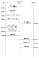
図1において、デジタル複合機(MFP)20は、コントローラユニット200、プリンタ部210、スキャナ部220、操作部230、無線USBアンテナ21を備えている。コントローラユニット200は、CPU110、RAM111、ROM112、無線通信I/F113、プリンタ部I/F114、スキャナ部I/F115を備えている。更に、コントローラユニット200は、操作部I/F116、メモリカードI/F117、内部バス118を備えている。
In FIG. 1, the digital multifunction peripheral (MFP) 20 includes a
プリンタ部210は、用紙に画像を印刷する画像出力デバイスである。スキャナ部220は、原稿から画像を読み取る画像入力デバイスである。操作部230は、デジタル複合機に対する各種設定や指示を行うための入力部、各種表示を行う表示部を備える。コントローラユニット200は、画像情報やデバイス情報の入出力を行うためのものであり、プリンタ部210、スキャナ部220、操作部230と接続される。また、コントローラユニット200は、無線通信I/F113、無線USBアンテナ21を介してホストPCと通信可能に無線通信により接続される。
The
CPU110は、内部バス118を介して上記各部を制御するものであり、本発明のプログラムに基づき図10のフローチャートに示す処理を実行する。RAM111は、CPU110が動作するためのシステムワークメモリ、画像データを一時記憶するための画像メモリとして用いられる。ROM112には、ブートプログラム、本発明のプログラム、システムアプリケーションプログラム等が格納されている。
The
プリンタ部I/F114は、プリンタ部210と接続し、プリンタ部210のCPU(不図示)と通信を行うと共に、印刷対象の画像データの同期系/非同期系の変換を行う。スキャナ部I/F115は、スキャナ部220と接続し、スキャナ220のCPU(不図示)と通信を行うと共に、原稿から読み取った画像データの同期系/非同期系の変換を行う。操作部I/F116は、操作部(ユーザインタフェース)230とのインタフェースを司るものである。操作部I/F116は、操作部230に表示する画像データを操作部230に対して出力し、操作部230からユーザが入力した情報をCPU110に伝える。
The printer unit I /
無線通信I/F113は、無線USBアンテナ21を介しホストPCに接続することでホストPCとの間で無線USBによる通信を行い、印刷用の画像データの入出力やデジタル複合機の制御に関わる情報の入出力を行う。メモリカードI/F117は、メモリカード240に画像データ等を書き込む処理或いは読み出す処理を行う。
The wireless communication I /
メモリカード240(記憶媒体)は、画像データ等のファイルを格納するものであり、スキャナ部220で原稿から読み取った画像データの書き込みや、プリンタ部210で印刷する画像データの読み出しが可能である。また、メモリカード240は、無線USBアンテナ21及び無線通信I/F113を介してデジタル複合機に無線通信接続したホストPCがファイルシステムとしてマウントし、ファイル操作を行うことも可能である。尚、メモリカード240は、デジタル複合機に着脱可能な携帯型メモリ、デジタル複合機に内蔵されるメモリのどちらでも構わない。
The memory card 240 (storage medium) stores files such as image data, and can write image data read from a document by the
図2は、デジタル複合機のコントローラオペレーティングシステム(以後OS)の構成を示すブロック図である。 FIG. 2 is a block diagram showing a configuration of a controller operating system (hereinafter referred to as OS) of the digital multi-function peripheral.
図2において、コントローラOS300は、無線通信制御モジュール310、メモリ制御モジュール320から構成されている。無線通信制御モジュール310は、無線通信制御部311、ホストリスト記憶部312、ホストリスト管理部313、処理要求検知部314から構成されている。メモリ制御モジュール320は、メモリ制御部321、マウント状態保持部322、アンマウント要求部323から構成されている。コントローラOS300は、デジタル複合機20のCPU110によりRAM111を用いて実行されるものであり、画像処理、プリント処理、スキャン処理、ホストPCとの通信制御処理等のデジタル複合機全般の制御を行う。
In FIG. 2, the
無線通信制御モジュール310において、無線通信制御部311は、無線通信I/F113のハードウエア制御を行う。ホストリスト記憶部312は、図16に示したホストリストを記憶する。ホストリスト管理部313は、以下のホストリストの登録処理を行う。ホストリスト管理部313は、ホストPCからビーコンを受信すると、ホスト名をホストリスト記憶部312のホストリストに追加する。また、ホストリスト管理部313は、ホストPCとの無線通信接続が切断されると、ホストリストの当該ホストPCに対応する第1番目のホスト情報(識別情報)を削除し、第2番目以降のホスト情報(識別情報)を繰り上げる。
In the wireless
処理要求検知部314は、ホストリストを参照して現在接続中のホストPC以外のホストPCからの処理要求受けを検知する。処理要求検知部314は、ホストリスト記憶部312のホストリストの第1番目のホスト情報と第2番目のホスト情報とを比較する。そして、第1番目及び第2番目のホスト情報が互いに異なるホスト情報である場合に、他のホストPCからの処理要求を受けたと判断する。
The processing
メモリ制御モジュール320において、メモリ制御部321は、メモリカードI/F117のハードウエア制御を行う。マウント状態保持部322は、ホストPCによるメモリカード240のマウント状態を示す情報を保持する。アンマウント要求部323は、ホストPCに対してメモリカード240のファイルシステムからのアンマウントを要求する。
In the
図3は、外部装置の一例であるホストPCのホストコントローラを中心とした構成を示すブロック図である。 FIG. 3 is a block diagram showing a configuration centering on the host controller of the host PC which is an example of the external apparatus.
図3において、ホストPC10は、ホストコントローラ100、ディスプレイ101、無線USBアンテナ11、キーボード、マウス(不図示)を備えている。ホストコントローラ100は、CPU102、ROM103、RAM104、HDD(ハードディスクドライブ)105、表示制御部106を備えている。更に、ホストコントローラ100は、各種IO(Input Output)I/F制御部107、無線通信I/F108、システムバス109を備えている。
In FIG. 3, the
ホストコントローラ100は、ディスプレイ101、キーボード、マウスと接続されており、無線USBアンテナ11を介して無線USB通信の制御を行う。CPU102は、システムバス109を介して上記各部を制御し、ホストコントローラ内部で行われる各種処理について統括的に制御すると共に、本発明のプログラムに基づき図11のフローチャートに示す処理を実行する。ROM103には、ブートプログラム、本発明のプログラムが格納されている。RAM104は、CPU102が動作するためのシステムワークメモリとして用いられる。
The
HDD105は、システムソフトウェアや画像データを格納する。表示制御部106は、ディスプレイ101に表示する画像データをディスプレイ101に対して出力する。各種IO I/F107は、キーボードやマウスとの間のデータ入出力のインタフェースとなるものであり、有線USB等の制御を司る。また、各種IO I/F107は、LAN等の通信網との間の通信制御を司る。無線通信I/F108は、ホストPC外部に無線USB通信を行うデバイスがある場合(本実施の形態ではデジタル複合機)、無線USBアンテナ11を介して無線USB通信の制御を行う。
The
図4は、ホストPCのホストOSの構成を示すブロックである。 FIG. 4 is a block diagram showing the configuration of the host OS of the host PC.
図4において、ホストPC10のホストOS150は、ファイルシステム管理部160、無線通信制御モジュール170から構成されている。無線通信制御モジュール170は、無線通信制御部171、マウントステータス通知部172、アンマウント要求部173、ファイルシステム入出力部174から構成されている。ホストOS150は、ホストPC10のCPU102によりROM103、RAM104、HDD105を用いて実行されるものであり、ホストPC全般の制御を行う。
4, the
ファイルシステム管理部160は、ホストPCのファイルシステムを管理するものであり、機器内部のHDD105のみならず、機器外部に接続される記憶装置をファイルシステムとして管理する。本実施の形態では、デジタル複合機が備えるメモリカード240をファイルシステムとして利用する場合の管理を行うことを想定している。
The file
無線通信制御モジュール170において、無線通信制御部171は、無線通信I/F108のハードウエアの制御を行う。マウントステータス通知部172は、デジタル複合機に対してファイルシステムのマウント状態を通知する。アンマウント要求部173は、ファイルシステム管理部160に対してファイルシステムのアンマウント要求を発生する。ファイルシステム入出力部174は、デジタル複合機とファイルシステム管理部160との間のファイルデータの転送を行う。
In the wireless
次に、上記構成を有する本実施の形態のデジタル複合機とホストPCの動作について図5乃至図11を参照しながら詳細に説明する。 Next, operations of the digital multi-function peripheral having the above-described configuration and the host PC will be described in detail with reference to FIGS.
<デジタル複合機からホストPCへのメモリファイルシステムアンマウント要求>
図5は、メモリファイルアンマウントの仕組みを示すシーケンス図である。
<Memory file system unmount request from digital MFP to host PC>
FIG. 5 is a sequence diagram showing a mechanism of memory file unmount.
図5において、メモリカードI/F117を備えるデジタル複合機(デバイス)を複数のホストPC(ホストPC1(第1の外部装置)、ホストPC2(第2の外部装置))が共用する場合を説明する。
In FIG. 5, a case where a plurality of host PCs (host PC 1 (first external device) and host PC 2 (second external device)) share a digital multi-function peripheral (device) having a memory card I /
まず、ホストPC1は、ジョブ処理要求としてビーコンをデバイスに送信し(ステップS3000)、これを受けたデバイスがホストPC1に対して接続要求を送信し(ステップS3001)、無線通信接続を確立する。ホストPC1は、デバイスとの無線通信接続を確立した後、デバイスのメモリカード240をマウントした後(ステップS3002)、ユーザからの指示応じてメモリカード240内のファイルを操作する(ステップS3003)。
First, the
ここで、ホストPC1がS3004でメモリカード240のアンマウント処理を行う前に、ホストPC2からジョブ処理要求を受けると(ステップS3100)、デバイスは、次の要求を行う。即ち、現在接続中のホストPC1に対してアンマウント処理を行うよう要求する(ステップS3201)。
Here, when the
この要求を受けたホストPC1は、ファイルシステムの状態を確認し、アンマウント可能であればメモリのアンマウントを行う(ステップS3004)。具体的には、例えばメモリ内のファイルを実行中か否かを判定し、ファイルを実行中でなければアンマウント可能であるものと判定する。これにより、ファイルシステムをエラー状態とすることなく、デバイスはホストPC1との通信を切断することができる(ステップS3005)。その後、ホストPC2に対して接続要求を送信し(ステップS3101)、ホストPC2からプリントデータを受信して(ステップS3102)プリントジョブを実行した後、ホストPC2との通信を切断する(ステップS3103)。
Receiving this request, the
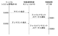
<ホストPCからのメモリカードファイルシステムマウント制御>
図6は、デジタル複合機のメモリカードファイルシステムのマウントに関わる制御を示すシーケンス図である。
<Memory card file system mount control from host PC>
FIG. 6 is a sequence diagram showing control related to mounting of the memory card file system of the digital multi-function peripheral.
図6において、無線通信I/F113と無線通信制御モジュール310の処理関係をシーケンスに従い説明する。尚、本項で説明する内容は、図5で説明したメモリファイルマウント(ステップS3002)とメモリファイルアンマウント(ステップS3004)の処理に対応するデジタル複合機側の内部処理である。
In FIG. 6, the processing relationship between the wireless communication I /
デジタル複合機の無線通信I/F113が、ホストPCからのファイルシステムのマウント指示を受信する(ステップS4000)。これに伴い、無線通信制御モジュール310から、メモリ制御モジュール320に対してメモリカードマウントを通知する(ステップS4001)。これにより、マウント状態保持部322にメモリマウント状態を示す情報が保持される。
The wireless communication I /
一方、デジタル複合機の無線通信I/F113が、ホストPCからのファイルシステムのアンマウント指示を受信する(ステップS4002)。これに伴い、無線通信制御モジュール310から、メモリ制御モジュール320に対してメモリカードアンマウントを通知する(ステップS4003)。これにより、マウント状態保持部322にメモリアンマウント状態を示す情報が保持される。
On the other hand, the wireless communication I /
<デジタル複合機からホストPCに対するファイルシステムアンマウント要求>
図7は、デジタル複合機からホストPCに対するファイルシステムアンマウント要求を発生する処理を示すシーケンス図である。
<File system unmount request from the digital MFP to the host PC>
FIG. 7 is a sequence diagram showing processing for generating a file system unmount request from the digital multifunction peripheral to the host PC.
図7において、無線通信I/F113と無線通信制御モジュール310の処理関係をシーケンスに従い説明する。上述した図6の通常処理と異なる特徴部分を重点に説明する。
In FIG. 7, the processing relationship between the wireless communication I /
デジタル複合機の無線通信I/F113が、他ホストPCからのビーコンを受信すると(ステップS4102)、処理要求検知部314が他ホストPCからの処理要求を検知する。そして、他ホストPCからの処理要求を受けたことがメモリ制御モジュール320に通知される(ステップS4103)。
When the wireless communication I /
メモリ制御モジュール320では、マウント状態保持部322がメモリマウント状態を示す情報を保持しているため、アンマウント要求部323がアンマウント要求を無線通信制御モジュール310に発行する(ステップS4104)。これに伴い、無線通信制御モジュール310は、無線通信制御部311を通じてホストアンマウント要求をホストPCに送信する(ステップS4105)。
In the
尚、S4100、S4101、S4106及びS4107では、それぞれ図6のS4000、S4001、S4002及びS4003に対応する処理が実行されるため説明は省略する。 In S4100, S4101, S4106, and S4107, the processing corresponding to S4000, S4001, S4002, and S4003 in FIG.
<デジタル複合機へのメモリカードファイルシステムマウント制御>
図8は、ホストPCのメモリカードファイルシステムのマウントに関わる制御を示すシーケンス図である。
<Memory card file system mount control to digital multifunction devices>
FIG. 8 is a sequence diagram showing control related to mounting of the memory card file system of the host PC.
図8において、無線通信I/F108と、無線通信制御モジュール170、ファイルシステム管理部160との処理関係をシーケンスに従い説明する。尚、本項で説明する内容は、図5で説明したメモリファイルマウント(ステップS3002)とメモリファイルアンマウント(ステップS3004)の処理に対応するホストPC側の内部処理である。
In FIG. 8, the processing relationship among the wireless communication I / F 108, the wireless
ホストPCによるファイルシステム管理部160のマウント指示(ステップS5000)が、無線通信制御モジュール170に通知される。これに伴い、マウントステータス通知部172が、無線通信制御部171を介して無線通信I/F108からデジタル複合機にファイルシステムマウント状態を通知する(ステップS5001)。
The mount instruction (step S5000) of the file
ホストPCによるファイルシステム管理部160のアンマウント指示(ステップS5002)が、無線通信制御モジュール170に通知される。これに伴い、マウントステータス通知部172が、無線通信制御部171を介して無線通信I/F108からデジタル複合機にファイルシステムアンマウント状態を通知する(ステップS5003)。
An unmount instruction (step S5002) of the file
<ホストPCがデジタル複合機から受信したファイルシステムアンマウント要求処理>
図9は、ホストPCがデジタル複合機から受信したファイルシステムアンマウント要求に対する処理を示すシーケンス図である。
<File system unmount request processing received by host PC from digital MFP>
FIG. 9 is a sequence diagram showing processing for a file system unmount request received by the host PC from the digital multifunction peripheral.
図9において、無線通信I/F108と、無線通信制御モジュール170、ファイルシステム管理部160との処理関係をシーケンスに従い説明する。上述した図8の通常処理と異なる特徴部分を重点に説明する。
In FIG. 9, the processing relationship among the wireless communication I / F 108, the wireless
ホストPCの無線通信制御部171が、無線通信I/F108を介してデジタル複合機からアンマウント要求を受信する(ステップS5102)。これに伴い、アンマウント要求部173は、ファイルシステム管理部160に対してファイルシステムのアンマウント要求を発生する(ステップS5103)。ファイルシステム管理部160は、ファイルシステムをアンマウント状態に移行させる。
The wireless
ファイルシステムがアンマウント状態になると、ファイルシステム管理部160は、ファイルシステムのアンマウント指示を行う(ステップS5104)。これに伴い、マウントステータス通知部172は、無線通信制御部171を介して無線通信I/F108からデジタル複合機にファイルシステムアンマウント状態を通知する(ステップS5105)。尚、S5100及びS5101は、それぞれ図8のS5000及びS5001に対応する処理が実行されるため説明は省略する。
When the file system is unmounted, the file
<デジタル複合機内部のメモリアンマウント処理>
図10は、デジタル複合機のメモリアンマウント処理を示すフローチャートである。本処理は、図7のステップS4103からステップS4107までのシーケンスにおいて、デジタル複合機内部での処理を示すものであり、デジタル複合機のCPU110の制御の下でコントローラOS300が処理を行う。
<Memory unmount processing inside the digital MFP>
FIG. 10 is a flowchart showing memory unmount processing of the digital multi-function peripheral. This processing shows processing inside the digital multi-function peripheral in the sequence from step S4103 to step S4107 in FIG. 7, and the
図10において、デジタル複合機とホストPC1とが通信している状態にあるものとする。デジタル複合機のコントローラOS300は、処理要求検知部314の状態を確認、即ち、新規ホストPC(ホストPC2)がデジタル複合機に対して処理要求を出してきたかを確認する(ステップS1000)。
In FIG. 10, it is assumed that the digital MFP and the
次に、コントローラOS300は、ステップS1000で確認した処理要求検知部314の状態を判断する(ステップS1001)。新規ホストPC(ホストPC2)からの処理要求がない場合は、ステップS1000に戻る。新規ホストPC(ホストPC2)からの処理要求がある場合は、コントローラOS300は、マウント状態保持部322の状態を確認する(ステップS1002)。
Next, the
次に、コントローラOS300は、ステップS1002で確認したマウント状態保持部322の状態を判断する(ステップS1003)。ホストPCがメモリカード240をマウントしている状態でない場合は、ステップS1008に進む。ホストPCがメモリカード240をマウントしている状態である場合は、コントローラOS300は、次の要求を送信する。即ち、アンマウント要求部323により無線通信I/F113を介してホストPCに対してアンマウントするよう要求を送信する(ステップS1004)。
Next, the
次に、コントローラOS300は、後述の図11のステップS2005でホストPC1から送信されるステータスを取得する(ステップS1005)。更に、コントローラOS300は、取得したステータスがホストPC1からのアンマウントの指示であるか否かを判断する(ステップS1006)。ホストPC1からのアンマウントの指示でない場合は、ステップS1005に戻る。ホストPC1からのアンマウントの指示である場合は、コントローラOS300は、マウント状態保持部322の保持状態、即ち、ホストPC1によるメモリカードのマウント状態をクリア(解除)する(ステップS1007)。
Next, the
更に、コントローラOS300は、ホストPC1によるメモリカードのマウント状態をクリアしたことに伴い、ホストPC1がメモリカード240をマウントしていない状態をコントローラOS300内に保持する。次に、コントローラOS300は、無線通信制御部311により、無線通信をしている状態にあったホストPC1との無線通信接続を切断する(ステップS1008)。これにより、本処理を終了する。この後は、新規ホストPC(ホストPC2)と無線通信接続を開始する。
Further, the
<ホストPC内部のメモリアンマウント処理>
図11は、ホストPCのメモリアンマウント処理を示すフローチャートである。本処理は、図9のステップS5102からステップS5105までのシーケンスにおいて、ホストPC内部での処理を示すものであり、ホストPCのCPU102の制御の下でホストOS150が処理を行う。
<Memory unmount processing inside the host PC>
FIG. 11 is a flowchart showing memory unmount processing of the host PC. This processing shows processing inside the host PC in the sequence from step S5102 to step S5105 in FIG. 9, and the
図11において、ホストPCのホストOS150は、無線通信制御部171により無線通信I/F108を介して、図10のステップS1004でデジタル複合機から送信されたコマンドを受信する(ステップS2000)。次に、ホストOS150は、ステップS2000で受信したコマンドの内容がデジタル複合機からのアンマウント要求であるか否かを判断する(ステップS2001)。デジタル複合機からのアンマウント要求でない場合は、ステップS2000に戻る。
In FIG. 11, the
デジタル複合機からのアンマウント要求である場合は、ホストOS150は、アンマウント要求部173によりファイルシステム管理部160からファイルシステムの状態を取得する(ステップS2002)。次に、ホストOS150は、ステップS2002で取得したファイルシステムの状態に基づき、ファイルシステムでアンマウント可能であるか否かを判断する(ステップS2003)。ファイルシステムでアンマウント可能でない場合は、ステップS2002に戻る。
If the request is an unmount request from the digital multifunction peripheral, the
ファイルシステムでアンマウント可能である場合は、ホストOS150は、ファイルシステム入出力部174によりファイルシステムのアンマウント許可を行う(ステップS2004)。次に、ホストOS150は、マウントステータス通知部172により無線通信I/F108を介してデジタル複合機に対してアンマウントを指示するステータスを通知する(ステップS2005)。これにより、本処理を終了する。
If the file system can be unmounted, the
以上詳細に説明したように、本実施の形態によれば、以下の効果を奏する。デジタル複合機がホストPC1と無線通信を行っている状態で、ホストPC2から処理要求を受けた場合に、ホストPC1でメモリカードをマウントした状態であるか否かを判断する。ホストPC1でメモリカードをマウントした状態である場合、ホストPC1に対してメモリカードをアンマウントするよう要求する。ホストPC1からアンマウントの指示があった場合、ホストPC1によるメモリカードのマウント状態を解除してアンマウント状態とした後、ホストPC1との無線通信接続を切断し、ホストPC2と無線通信を開始する。
As described above in detail, according to the present embodiment, the following effects can be obtained. When a processing request is received from the
これにより、従来のようにデジタル複合機でホストPCのメモリカードジョブ実行中に他のホストPCからの処理要求を受けた場合に、他のホストPCとの通信を開始できないという課題を解消することが可能となる。また、従来のようにホストPCのメモリカードジョブ実行中にデジタル複合機が強制的にホストPCとの通信を切断した場合にエラー状態となるという課題を解消することが可能となる。これにより、ホストPC側でのエラーを発生することなく、通信切断処理を行うことが可能となる。また、1つのホストPCによるデジタル複合機の専有を避け、複数のホストPCによりデジタル複合機を共用することが可能となる。 This eliminates the problem that communication with another host PC cannot be started when a processing request is received from another host PC while the memory card job of the host PC is being executed in the digital multi-function peripheral as in the past. Is possible. Further, it is possible to solve the problem that an error state occurs when the digital multifunction peripheral forcibly disconnects communication with the host PC during execution of the memory card job of the host PC as in the prior art. As a result, the communication disconnection process can be performed without causing an error on the host PC side. In addition, it is possible to share the digital multi-function peripheral with a plurality of host PCs, while avoiding exclusive use of the digital multi-function peripheral with one host PC.
なお、上述の説明では、他のホストPCからの処理要求を受けた場合に、現在接続中のホストPCに対してメモリのアンマウントを要求する例について説明したが、他の態様であっても構わない。即ち、例えば現在接続中のホストPCに代わってデバイス自体がアンマウント処理を行い、現在接続中のホストPCとの通信を切断するようにしてもよい。この場合、通信を切断する前に、ホストPCに対してメモリをアンマウントしたことを通知するようにすればなおよい。 In the above description, when a processing request from another host PC is received, an example of requesting unmounting of memory from the currently connected host PC has been described. However, other modes may be used. Absent. That is, for example, the device itself may perform an unmount process in place of the currently connected host PC, and the communication with the currently connected host PC may be disconnected. In this case, it is better to notify the host PC that the memory has been unmounted before disconnecting the communication.
また、上述の説明では、他のホストPCからの処理要求を受けたことに応じて現在接続中のホストPCに対してメモリのアンマウントを要求する例について説明したが、以下のように要求するようにしてもよい。即ち、他のホストPCからの処理要求受け以外のタイミングで要求するようにしてもよい。例えば、ホストPCからの指示でメモリ内のデータを読み出してデバイスが印刷処理を行う場合に、印刷処理の完了に応じてホストPCに対してメモリのアンマウントを要求するようにしてもよい。或いは、メモリ内のファイルが所定時間操作されなかった場合に、タイムアウト処理としてホストPCに対してメモリのアンマウントを要求するようにすることもできる。 In the above description, an example has been described in which a memory PC is requested to be unmounted from the currently connected host PC in response to a processing request from another host PC. It may be. That is, the request may be made at a timing other than receiving a processing request from another host PC. For example, when the device performs print processing by reading data in the memory in response to an instruction from the host PC, the host PC may be requested to unmount the memory upon completion of the print processing. Alternatively, when a file in the memory has not been operated for a predetermined time, the host PC can be requested to unmount the memory as a timeout process.
〔他の実施の形態〕
本発明の目的は、以下の処理を実行することによっても達成される。即ち、上述した実施形態の機能を実現するソフトウェアのプログラムコードを記録した記憶媒体を、システム或いは装置に供給し、そのシステム或いは装置のコンピュータ(またはCPUやMPU等)が記憶媒体に格納されたプログラムコードを読み出す処理である。
[Other Embodiments]
The object of the present invention can also be achieved by executing the following processing. That is, a storage medium that records a program code of software that realizes the functions of the above-described embodiments is supplied to a system or apparatus, and a computer (or CPU, MPU, etc.) of the system or apparatus is stored in the storage medium. This is the process of reading the code.
この場合、記憶媒体から読み出されたプログラムコード自体が前述した実施の形態の機能を実現することになり、そのプログラムコード及び該プログラムコードを記憶した記憶媒体は本発明を構成することになる。 In this case, the program code itself read from the storage medium realizes the functions of the above-described embodiments, and the program code and the storage medium storing the program code constitute the present invention.
110 CPU
113 無線通信制御部
300 コントローラOS
110 CPU
113 Wireless
Claims (8)
データを記憶するメモリを通信可能に接続するための接続手段と、
前記第1の外部装置と通信している状態で前記第2の外部装置から処理要求を受けたことに応じて、該第1の外部装置が前記メモリをマウントしているか否かを判定する判定手段と、
前記判定手段により、前記第1の外部装置が前記メモリをマウントしていると判定された場合に、前記第1の外部装置に対して前記メモリをアンマウントするよう要求する要求手段と、
前記要求手段による要求に応じて前記第1の外部装置が前記メモリをアンマウントした後に前記第1の外部装置との通信を切断し、前記第2の外部装置との通信を開始する通信制御手段と、
を備えることを特徴とする情報処理装置。 An information processing apparatus capable of communicating with the first external device and the second external device,
Connection means for connecting a memory for storing data in a communicable manner;
Determining whether the first external device mounts the memory in response to receiving a processing request from the second external device while communicating with the first external device; Means,
Request means for requesting the first external device to unmount the memory when the determining means determines that the first external device is mounting the memory;
Communication control means for disconnecting communication with the first external apparatus after the first external apparatus unmounts the memory in response to a request from the request means, and starting communication with the second external apparatus; ,
An information processing apparatus comprising:
前記第1の外部装置または前記第2の外部装置から前記通信手段を介して処理要求を受けた場合に、該処理要求を送信した外部装置を示す識別情報を管理する管理手段と、
を更に備え、
前記通信制御手段は、前記管理手段により管理されている識別情報に基づいて、前記通信手段による前記第1の外部装置及び前記第2の外部装置との通信を制御することを特徴とする請求項1または2に記載の情報処理装置。 Communication means for performing wireless communication between the first external device and the second external device;
A management unit that manages identification information indicating an external device that has transmitted the processing request when a processing request is received from the first external device or the second external device via the communication unit;
Further comprising
The communication control means controls communication with the first external device and the second external device by the communication means based on identification information managed by the management means. The information processing apparatus according to 1 or 2.
前記第1の外部装置と通信している状態で前記第2の外部装置から処理要求を受けたことに応じて、該第1の外部装置が前記メモリをマウントしているか否かを判定する判定工程と、
前記判定工程で、前記第1の外部装置が前記メモリをマウントしていると判定された場合に、前記第1の外部装置に対して前記メモリをアンマウントするよう要求する要求工程と、
前記要求工程での要求に応じて前記第1の外部装置が前記メモリをアンマウントした後に前記第1の外部装置との通信を切断し、前記第2の外部装置との通信を開始する通信制御工程と、
を備えることを特徴とする情報処理装置の制御方法。 A control method for an information processing apparatus comprising a connection means for connecting a memory for storing data in a communicable manner and capable of communicating with the first external device and the second external device,
Determining whether the first external device mounts the memory in response to receiving a processing request from the second external device while communicating with the first external device; Process,
A requesting step of requesting the first external device to unmount the memory when it is determined in the determining step that the first external device is mounting the memory;
A communication control step of disconnecting communication with the first external device and starting communication with the second external device after the first external device unmounts the memory in response to a request in the request step When,
An information processing apparatus control method comprising:
Priority Applications (3)
| Application Number | Priority Date | Filing Date | Title |
|---|---|---|---|
| JP2009033900A JP5578793B2 (en) | 2009-02-17 | 2009-02-17 | Information processing apparatus, control method, and program |
| PCT/JP2010/052391 WO2010095670A1 (en) | 2009-02-17 | 2010-02-10 | Information processing apparatus, control method thereof, and storage medium |
| US13/124,477 US9268726B2 (en) | 2009-02-17 | 2010-02-10 | Information processing apparatus, control method thereof, and storage medium |
Applications Claiming Priority (1)
| Application Number | Priority Date | Filing Date | Title |
|---|---|---|---|
| JP2009033900A JP5578793B2 (en) | 2009-02-17 | 2009-02-17 | Information processing apparatus, control method, and program |
Publications (3)
| Publication Number | Publication Date |
|---|---|
| JP2010191584A JP2010191584A (en) | 2010-09-02 |
| JP2010191584A5 JP2010191584A5 (en) | 2012-03-22 |
| JP5578793B2 true JP5578793B2 (en) | 2014-08-27 |
Family
ID=42633950
Family Applications (1)
| Application Number | Title | Priority Date | Filing Date |
|---|---|---|---|
| JP2009033900A Expired - Fee Related JP5578793B2 (en) | 2009-02-17 | 2009-02-17 | Information processing apparatus, control method, and program |
Country Status (3)
| Country | Link |
|---|---|
| US (1) | US9268726B2 (en) |
| JP (1) | JP5578793B2 (en) |
| WO (1) | WO2010095670A1 (en) |
Families Citing this family (2)
| Publication number | Priority date | Publication date | Assignee | Title |
|---|---|---|---|---|
| JP2010152815A (en) * | 2008-12-26 | 2010-07-08 | Seiko Epson Corp | Information processor, information processing system, and control method of information processor |
| JP2016177642A (en) * | 2015-03-20 | 2016-10-06 | 株式会社リコー | Information processing device, information processing system, program and image processing system |
Family Cites Families (19)
| Publication number | Priority date | Publication date | Assignee | Title |
|---|---|---|---|---|
| JP2000222229A (en) * | 1999-02-04 | 2000-08-11 | Seiko Epson Corp | Method and device for exclusively controlling plural jobs, and medium recorded with exclusive control program for plural jobs |
| JP2002014871A (en) * | 2000-06-29 | 2002-01-18 | Fujitsu Ltd | Contents check method, contents update method and processor |
| JP3624166B2 (en) * | 2001-03-21 | 2005-03-02 | 京セラミタ株式会社 | Scanner device, printer device and digital copying machine connected to network |
| JP2004272800A (en) * | 2003-03-11 | 2004-09-30 | Sony Corp | Repeater for network apparatus, method for writing in removable storage device, and method for detecting insertion and ejection of the device |
| JP2005092523A (en) * | 2003-09-17 | 2005-04-07 | Fuji Photo Film Co Ltd | Data fetching method and device, as well as data fetching program |
| JP4600762B2 (en) | 2005-08-31 | 2010-12-15 | ソニー株式会社 | Information processing apparatus and method, and program |
| JP4566874B2 (en) * | 2005-10-04 | 2010-10-20 | 株式会社日立製作所 | Storage access management function and system in IP network |
| JP4902234B2 (en) | 2006-03-17 | 2012-03-21 | 株式会社リコー | Wireless USB system |
| US7478188B2 (en) * | 2006-06-02 | 2009-01-13 | Hewlett-Packard Development Company, L.P. | System and method for connecting a WUSB device to multiple WUSB hosts |
| WO2007148372A1 (en) * | 2006-06-19 | 2007-12-27 | Fujitsu Limited | Radio communication device and its communication method |
| JP2008052318A (en) * | 2006-08-22 | 2008-03-06 | Matsushita Electric Ind Co Ltd | Data processing unit, data processing method, and multifunction printer |
| JP4793177B2 (en) * | 2006-08-30 | 2011-10-12 | ブラザー工業株式会社 | Information processing apparatus, information processing system, and program |
| JP4948971B2 (en) * | 2006-11-01 | 2012-06-06 | 株式会社リコー | Wireless USB host |
| KR101141276B1 (en) * | 2007-06-04 | 2012-05-04 | 삼성전자주식회사 | Communication method of host apparatus capable of connecting with device using WUSB and system including the host apparatus and the device |
| KR100967400B1 (en) * | 2007-12-11 | 2010-07-01 | 한국전자통신연구원 | Wireless USB device apparatus for networking with plurality of wireless USB host and method thereof |
| US8136085B2 (en) * | 2008-01-29 | 2012-03-13 | Hewlett-Packard Development Company, L.P. | System and method for implementing a shared platform or software resource for coupled computing devices |
| JP4524316B2 (en) * | 2008-01-30 | 2010-08-18 | 株式会社沖データ | Image processing apparatus and image processing system |
| JP5606293B2 (en) * | 2010-11-22 | 2014-10-15 | キヤノン株式会社 | Data processing apparatus, access control method and program |
| US20120190406A1 (en) * | 2011-01-24 | 2012-07-26 | I O Interconnect, Ltd. | Docking station, portable device capable of multimedia data playback management, and methods thereof |
-
2009
- 2009-02-17 JP JP2009033900A patent/JP5578793B2/en not_active Expired - Fee Related
-
2010
- 2010-02-10 US US13/124,477 patent/US9268726B2/en not_active Expired - Fee Related
- 2010-02-10 WO PCT/JP2010/052391 patent/WO2010095670A1/en active Application Filing
Also Published As
| Publication number | Publication date |
|---|---|
| WO2010095670A1 (en) | 2010-08-26 |
| US9268726B2 (en) | 2016-02-23 |
| JP2010191584A (en) | 2010-09-02 |
| US20110208942A1 (en) | 2011-08-25 |
Similar Documents
| Publication | Publication Date | Title |
|---|---|---|
| EP2544426B1 (en) | Image forming apparatus communicating with external device through network, network system, method of controlling image forming apparatus, program, and storage medium | |
| US8854388B2 (en) | Image processing apparatus and memory management method for image processing apparatus | |
| KR101409508B1 (en) | Information processing apparatus, print data processing method therein and storage medium storing program thereof | |
| JP6331302B2 (en) | Information processing system, information acquisition apparatus, server, program, and information processing method | |
| EP2400394B1 (en) | Information processing apparatus including storage unit and connection unit for connecting external storage device | |
| US8683124B2 (en) | Device, control method thereof, and program | |
| JP6066006B2 (en) | Image forming apparatus | |
| JP2008030287A (en) | Printing apparatus, printing system and program | |
| JP5949007B2 (en) | Job execution apparatus, program, and execution control method | |
| JP5578793B2 (en) | Information processing apparatus, control method, and program | |
| US8934129B2 (en) | Image forming apparatus and image forming method erasing print data in descending or ascending order of file size dependent upon free memory space available | |
| KR100661170B1 (en) | image forming device and controlling method thereof | |
| EP2426592B1 (en) | Image forming apparatus and method of forming image thereof | |
| JP2008283441A (en) | Image processing system, image reader, and control program | |
| US20120062920A1 (en) | Image processor and image processing system | |
| JP2005115427A (en) | Peripheral device locally connected to computer | |
| EP2380341B1 (en) | Image forming apparatus, control method for image forming apparatus, and storage medium | |
| JP4276885B2 (en) | Image forming apparatus and path designation method | |
| JP3910992B2 (en) | Image forming apparatus, image forming method, and image forming program | |
| JP4428704B2 (en) | Printing system | |
| US20230153050A1 (en) | Display apparatus capable of displaying slide show, method for controlling the same, and storage medium | |
| JP2004046804A (en) | Image forming apparatus and data processing method | |
| JP3890160B2 (en) | Printing system, control method in printing system, and storage medium | |
| JP2004048696A (en) | Image forming apparatus and data processing method | |
| JP6395380B2 (en) | Information processing apparatus, information processing method, and program |
Legal Events
| Date | Code | Title | Description |
|---|---|---|---|
| A521 | Written amendment |
Free format text: JAPANESE INTERMEDIATE CODE: A523 Effective date: 20120207 |
|
| A621 | Written request for application examination |
Free format text: JAPANESE INTERMEDIATE CODE: A621 Effective date: 20120207 |
|
| A131 | Notification of reasons for refusal |
Free format text: JAPANESE INTERMEDIATE CODE: A131 Effective date: 20130910 |
|
| TRDD | Decision of grant or rejection written | ||
| A01 | Written decision to grant a patent or to grant a registration (utility model) |
Free format text: JAPANESE INTERMEDIATE CODE: A01 Effective date: 20140609 |
|
| A61 | First payment of annual fees (during grant procedure) |
Free format text: JAPANESE INTERMEDIATE CODE: A61 Effective date: 20140708 |
|
| LAPS | Cancellation because of no payment of annual fees |