JP5574591B2 - Pressurizing mechanism, tire vulcanizing apparatus and tire manufacturing method - Google Patents
Pressurizing mechanism, tire vulcanizing apparatus and tire manufacturing method Download PDFInfo
- Publication number
- JP5574591B2 JP5574591B2 JP2008224992A JP2008224992A JP5574591B2 JP 5574591 B2 JP5574591 B2 JP 5574591B2 JP 2008224992 A JP2008224992 A JP 2008224992A JP 2008224992 A JP2008224992 A JP 2008224992A JP 5574591 B2 JP5574591 B2 JP 5574591B2
- Authority
- JP
- Japan
- Prior art keywords
- tire
- pressure
- pressurizing
- contact
- mold
- Prior art date
- Legal status (The legal status is an assumption and is not a legal conclusion. Google has not performed a legal analysis and makes no representation as to the accuracy of the status listed.)
- Expired - Fee Related
Links
Images

Landscapes
- Reciprocating Pumps (AREA)
- Moulds For Moulding Plastics Or The Like (AREA)
- Heating, Cooling, Or Curing Plastics Or The Like In General (AREA)
Description
本発明は、ピストン・シリンダ機構を作動させて被加圧体を加圧する加圧機構と、この加圧機構を使用して生タイヤ(グリーンタイヤ)を収納する加硫モールドを型締め方向に加圧して生タイヤを加硫するタイヤ加硫装置、及びタイヤ製造方法に関する。 According to the present invention, a pressurizing mechanism that pressurizes an object to be pressurized by operating a piston / cylinder mechanism, and a vulcanization mold that accommodates a raw tire (green tire) using this pressurizing mechanism is added in the mold clamping direction. The present invention relates to a tire vulcanizing apparatus and a tire manufacturing method for vulcanizing a raw tire by pressing.
空気入りタイヤは、一般に、未加硫ゴム等からなる各種のタイヤ構成部材により生タイヤを成形した後、タイヤ加硫装置の加硫モールド内に収納されて加硫成型して製造される。また、このタイヤ加硫装置として、従来、装置のベース部と、加硫モールドが取り付けられたプレートとの間に、ピストン・シリンダ機構からなる複数の加圧機構を設け、これにより、当接するプレートを介して加硫モールドを加圧して所定圧力で締め付けつつ、生タイヤを加硫する装置が知られている(特許文献1参照)。 In general, a pneumatic tire is manufactured by molding a raw tire with various tire constituent members made of unvulcanized rubber or the like, and then storing the tire in a vulcanization mold of a tire vulcanizer. In addition, as a tire vulcanizing device, conventionally, a plurality of pressurizing mechanisms including a piston / cylinder mechanism are provided between a base portion of the device and a plate to which a vulcanizing mold is attached, and thereby a plate that comes into contact There is known an apparatus for vulcanizing a raw tire while pressurizing a vulcanization mold via a bolt and tightening the mold at a predetermined pressure (see Patent Document 1).
ところで、このように使用される加圧機構は、プレートの当接面の傾きや重心の偏り等により加圧時に荷重が偏芯して付加され、この偏芯荷重が生じた状態でピストンが昇降変位してシリンダの内周面に対して摺動等することで、ピストン外周面やシリンダ内周面に摩耗や傷が生じることがある。同時に、この傷で加圧機構内に設けられたOリング等のパッキンが傷つき、或いは、シリンダとピストン間の隙間寸法に対して摩耗が所定量進行した段階で、作動時の圧力によりパッキンが摩耗部からはみ出して切れる等、パッキンが破損する要因になることもある。その結果、従来の加圧機構では、ピストンやシリンダ、又はパッキン等の部品の耐久性が低下して、それらの寿命が短くなる恐れがあり、特に、加圧力の最大値が大きい大型サイズでは、寿命がより短くなる傾向がある。 By the way, the pressurizing mechanism used in this way is applied with an eccentric load during pressurization due to the inclination of the contact surface of the plate or the deviation of the center of gravity. Displacement and sliding with respect to the inner peripheral surface of the cylinder may cause wear and scratches on the piston outer peripheral surface and the cylinder inner peripheral surface. At the same time, the packing such as an O-ring provided in the pressurizing mechanism is damaged by this scratch, or when the wear progresses by a predetermined amount with respect to the gap between the cylinder and the piston, the packing is worn by the pressure during operation. It may cause damage to the packing, such as cutting off from the part. As a result, in the conventional pressurizing mechanism, the durability of parts such as pistons, cylinders, packing, etc. may be reduced, and their life may be shortened.In particular, in a large size where the maximum value of the applied pressure is large, There is a tendency for the lifetime to be shorter.
また、タイヤ加硫装置では、複数の加圧機構により、同じ加硫モールドを同時に加圧して締め付けるのが一般的である。しかしながら、このような複数の加圧機構を全て同じように動作させるのは極めて困難であり、互いの動作やタイミングのずれ等により各々偏芯荷重が生じ易く、偏芯荷重や、それに伴う問題を回避するのは難しい。 In general, in a tire vulcanizing apparatus, the same vulcanization mold is simultaneously pressurized and tightened by a plurality of pressure mechanisms. However, it is extremely difficult to operate all of the plurality of pressurizing mechanisms in the same manner, and an eccentric load is likely to be generated due to mutual operation and timing shift, etc. It is difficult to avoid.
本発明は、前記従来の問題に鑑みなされたものであって、その目的は、ピストン・シリンダ機構により被加圧体を加圧する加圧機構に発生する偏芯荷重を低減し、シリンダやピストンに摩耗や傷が生じ、或いは、パッキンが損傷等するのを抑制して、各部品の耐久性を高めて寿命を延長することである。 The present invention has been made in view of the above-described conventional problems, and an object of the present invention is to reduce the eccentric load generated in a pressurizing mechanism that pressurizes an object to be pressurized by a piston / cylinder mechanism, and It is to suppress wear and scratches or damage to the packing, thereby enhancing the durability of each component and extending the life.
本発明は、ピストン・シリンダ機構により被加圧体を加圧する加圧機構であって、ピストン・シリンダ機構のピストンと一体に変位してシリンダから進退し、被加圧体に圧力を伝達する圧力伝達体を備え、圧力伝達体は、圧力伝達体に形成された環状の周壁との間に隙間ができるように周壁内の凹所に収容され、被加圧体と当接しその傾きに応じて傾斜可能な当接部材と、当接部材と接する凹所の底面に形成されて当接部材を傾斜可能に支承するとともに、面接触可能な当接部材の被支承面を摺動させて当接部材を周壁内で変位させて傾斜させる支承面を有し、圧力伝達体の当接部材を当接する被加圧体の傾きに応じて傾斜させ、圧力伝達体及び当接部材を介して、ピストン・シリンダ機構から被加圧体に圧力を作用させて加圧することを特徴とする。
また、本発明は、生タイヤを収納する加硫モールドを加圧して型締めし、生タイヤを加硫するタイヤ加硫装置であって、加圧機構を備え、加圧機構により被加圧体である加硫モールドの圧力作用面を加硫モールドの型締め方向に加圧することを特徴とする。
更に、本発明は、生タイヤを収納する加硫モールドを加圧して型締めし、生タイヤを加硫してタイヤを製造するタイヤ製造方法であって、加圧機構により被加圧体である加硫モールドの圧力作用面を加硫モールドの型締め方向に加圧する工程と、該加圧により加硫モールドを加圧して型締めし、加硫モールドに収納された生タイヤを加硫する工程と、を有することを特徴とする。
The present invention is a pressurizing mechanism that pressurizes an object to be pressurized by a piston / cylinder mechanism, and is a pressure that is displaced integrally with the piston of the piston / cylinder mechanism, moves forward and backward from the cylinder, and transmits pressure to the object to be pressurized. The pressure transmission body is housed in a recess in the peripheral wall so that a gap is formed between the pressure transmission body and the annular peripheral wall formed in the pressure transmission body, and comes into contact with the pressurized body according to its inclination. An abutting member that can be tilted and formed on the bottom surface of a recess that is in contact with the abutting member to support the abutting member so as to be tiltable, and to be abutted by sliding the supported surface of the abutting member that can contact the surface The member has a bearing surface that is displaced in the peripheral wall to be inclined, and the piston is inclined through the pressure transmission body and the contact member by inclining the contact member of the pressure transmission body in accordance with the inclination of the pressed member.・ Features that pressure is applied to the object to be pressurized from the cylinder mechanism. To.
The present invention also relates to a tire vulcanizing apparatus that pressurizes and clamps a vulcanization mold that accommodates a raw tire to vulcanize the raw tire, and includes a pressurizing mechanism, and a pressurizing body is provided by the pressurizing mechanism. The pressure acting surface of the vulcanization mold is pressurized in the mold clamping direction of the vulcanization mold.
Furthermore, the present invention is a tire manufacturing method for manufacturing a tire by pressurizing and clamping a vulcanizing mold for housing a raw tire and vulcanizing the raw tire, and is a member to be pressed by a pressurizing mechanism. A step of pressing the pressure acting surface of the vulcanization mold in the mold clamping direction of the vulcanization mold, and a step of pressing the vulcanization mold by the pressurization and clamping the raw tire accommodated in the vulcanization mold It is characterized by having.
本発明によれば、ピストン・シリンダ機構により被加圧体を加圧する加圧機構に発生する偏芯荷重を低減でき、シリンダやピストンに摩耗や傷が生じ、或いは、パッキンが損傷等するのを抑制して、各部品の耐久性を高めて寿命を延長することができる。 According to the present invention, the eccentric load generated in the pressurizing mechanism that pressurizes the object to be pressed by the piston / cylinder mechanism can be reduced, and the cylinder or piston is worn or scratched, or the packing is damaged. It is possible to increase the durability of each component and extend the service life.
以下、本発明の加圧機構と、この加圧機構を備えたタイヤ加硫装置、及び加圧機構を使用してタイヤを製造するタイヤ製造方法の一実施形態について、図面を参照して説明する。
本実施形態の加圧機構は、ピストン・シリンダ機構により加圧対象物である被加圧体を所定圧力で加圧する加圧装置を構成し、ここでは、生タイヤを加硫するタイヤ加硫装置に設けられ、その生タイヤを収納する加硫モールド等を加圧する場合を例に採り説明する。
Hereinafter, an embodiment of a pressure mechanism according to the present invention, a tire vulcanizing apparatus including the pressure mechanism, and a tire manufacturing method for manufacturing a tire using the pressure mechanism will be described with reference to the drawings. .
The pressurizing mechanism according to the present embodiment constitutes a pressurizing device that pressurizes an object to be pressurized with a predetermined pressure by a piston / cylinder mechanism, and here, a tire vulcanizing device for vulcanizing a raw tire A case where a vulcanizing mold or the like that accommodates the green tire is pressurized will be described as an example.
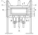
図1は、本実施形態のタイヤ加硫装置の要部を模式的に示す側面図であり、各構成を組み合わせて加硫モールドを閉じた状態を示している。
タイヤ加硫装置1は、図示のように、生タイヤ(図示せず)を収納する加硫モールド2と、その上下面にそれぞれ当接して配置された上プラテン3及び下プラテン4と、を備えている。
FIG. 1 is a side view schematically showing the main part of the tire vulcanizing apparatus of the present embodiment, and shows a state in which the vulcanization mold is closed by combining the components.
As shown in the figure, the tire vulcanizing apparatus 1 includes a
加硫モールド2は、例えば上下に対向する一対のサイドモールド及び、それらに挟まれた周方向に複数に分割された略環状のトレッドモールド等、複数に分割され、それらが組み合わされて生タイヤを収納するキャビティを区画する。また、加硫モールド2は、分割された各部を相対的に接近及び離反する方向に各々移動させて型締め及び型開きさせる移動機構を備え、これにより、キャビティを開放及び閉鎖して、生タイヤの内部への収納と、加硫後のタイヤの取り出しとが行われる。その際、加硫モールド2内には、内面側に膨張可能なブラダが配置される生タイヤが、又は、剛体コア上に形成された生タイヤが収納される。
The
上下のプラテン3、4は、この生タイヤを収納する加硫モールド2を加熱する加熱部材(熱板)であり、それぞれ加硫モールド2を挟んで、その上下面の略全体に亘って当接する板状に形成されている。各プラテン3、4は、例えば内部に形成された循環通路に供給手段から加熱媒体が供給され、この循環する加熱媒体により加熱されて当接する加硫モールド2に伝熱し、加硫モールド2を所定の加硫温度まで加熱して内部の生タイヤの加硫を進行させる。
The upper and
また、タイヤ加硫装置1は、これら上下のプラテン3、4にそれぞれ当接させて上下の断熱板5、6を配置するとともに、下断熱板6の下面に加圧プレート7を当接させ、かつ、それらの全体を挟んで上方にトッププレート8を、下方に下部プレート9を各々配置している。このトッププレート8と下部プレート9は、それらの間の各部よりも大きい板状に形成され、その外縁側に設けられた締結手段10により互いに締結され、間に位置する加硫モールド2、プラテン3、4、断熱板5、6、及び加圧プレート7の全体を挟み込んで固定する。更に、タイヤ加硫装置1は、この各プレート8、9を、加硫モールド2等を挟み込んだ状態で固定して保持する、左右に設置された保持装置11や、下部プレート9の下側に配置されたバグ調整装置12を備えている。
Further, the tire vulcanizing apparatus 1 is provided with upper and lower heat insulating plates 5 and 6 in contact with the upper and
タイヤ加硫装置1は、以上のように、生タイヤを加硫モールド2に収納して、上下のプラテン3、4等を挟んで各プレート8、9間に配置し、プラテン3、4を介して加硫モールド2を加熱して、生タイヤを加硫しつつ製品形状に成型する。その際、本実施形態では、生タイヤを収納する加硫モールド2を所定のタイミングで加圧して型締めし、加硫モールド2を締め付けながら、或いは、その内部の生タイヤに作用する圧力を調整等しながら加硫成型を進行させてタイヤを製造する。
As described above, the tire vulcanizing apparatus 1 accommodates a raw tire in the
そのため、このタイヤ加硫装置1は、加硫モールド2を型締め方向に加圧するための加圧機構20を備えており、ここでは、複数の加圧機構20を、下部プレート9の上面側に形成した凹部内に収納して取り付けている。タイヤ加硫装置1は、この加圧機構20により、上端部に当接する加圧プレート7を上方に向けて押圧し、その上方に配置された加硫モールド2の分割部を、他の分割部に向けて押圧して圧力を作用させる。このように、タイヤ加硫装置1は、下部プレート9と加圧プレート7との間に加圧機構20を設け、これにより、加圧プレート7等を介して、加硫モールド2又は内部の生タイヤを加圧する。
Therefore, the tire vulcanizing apparatus 1 includes a pressurizing
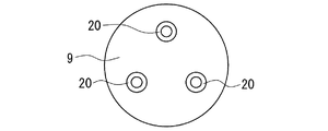
図2は、この加圧機構20の配置状態を示す模式図であり、上方から見た下部プレート9と加圧機構20とを抜き出して平面図で示している。
加圧機構20は、図示のように、円盤状の下部プレート9と同芯状に複数(ここでは3つ)、その周方向に沿って互いに等間隔に配置されている。また、加圧機構20は、上記したようにピストン・シリンダ機構からなり、それぞれシリンダ内で、油や気体等の作動媒体からの圧力(ここでは油圧)によりピストンを往復摺動させて所定方向に変位(移動)させることで、互いに同期して作動する。以下、この加圧機構20について、より詳細に説明する。
FIG. 2 is a schematic diagram showing an arrangement state of the
As shown in the drawing, a plurality of press mechanisms 20 (three in this case) are concentrically arranged with the disk-shaped
図3は、この加圧機構20の要部を模式的に示す側断面図である。
加圧機構20は、図示のように、一方(図では下方)の端部が閉鎖された略円筒状のシリンダ31と、その内周面を摺動して上下方向に変位する略円盤状のピストン32とを備え、それらによりピストン・シリンダ機構30を構成している。また、ピストン32と一体に形成された略円柱状の圧力伝達体40を備え、圧力伝達体40を、シリンダ31の端部(図では上端部)から、その内外に出入りさせてシリンダ31から進退させる。更に、加圧機構20は、ピストン32の外周部に環状のパッキン33(例えば、Oリング)を取り付けて、シリンダ31の内周面との間をシールしている。
FIG. 3 is a side sectional view schematically showing a main part of the
As shown in the figure, the
加圧機構20は、ピストン32を挟んでシリンダ31内に形成された各圧力室35、36へ、それぞれ上下の端部付近に連通する給排孔35K、36Kを介して、油圧ユニット(図示せず)から所定圧力の油を供給及び排出することで、ピストン32を所定方向(図では上下方向)へ変位させる。同時に、圧力伝達体40を、ピストン32と一体に変位させてシリンダ31から進退させ、そのシリンダ31から突出する上端部を、被加圧体である加圧プレート7の下面に当接させて、ピストン・シリンダ機構30からの圧力を伝達する。これにより、加圧プレート7及び加硫モールド2を上記したように加圧する。
The pressurizing
また、本実施形態の圧力伝達体40は、被加圧体と当接し、その傾きに応じて傾斜可能な当接部材41を有し、その被加圧体との当接面41T(ここでは、上端面)を、被加圧体に合わせて任意の方向に傾斜させる。この当接部材41により、圧力伝達体40は、当接面41Tを、当接する被加圧体の当接部(ここでは、対向する加圧プレート7の下面)の傾きに応じて、それと同じ方向及び角度に傾くように傾斜させて互いに当接させる。このようにして、加圧機構20は、加圧時に、圧力伝達体40の当接部材41(当接面41T)を、加圧プレート7の下面に合わせて傾斜させ、それらを全体に亘って当接させた状態で、圧力伝達体40及び当接部材41を介して、ピストン・シリンダ機構30から加圧プレート7に圧力を作用させて加圧する。また、ここでは、圧力伝達体40は、当接部材41を傾斜可能に支承する支承面42を有し、これにより、当接部材41を支承しつつ、当接面41Tを当接する加圧プレート7の下面の傾きに応じて傾斜させる。
In addition, the
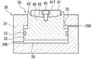
図4は、この当接部材41付近の圧力伝達体40を拡大して模式的に示す側断面図であり、図4Aは当接部材41が傾斜していない状態を、図4Bは当接部材41が傾斜した状態を、それぞれ示している。
具体的には、この圧力伝達体40は、図示のように、上端面の縁部に沿って環状の周壁43が形成され、周壁43内に当接部材41を収容する凹所Pを設けている。一方、当接部材41は、周壁43内(凹所P)に収容され、かつ、平面状の当接面41Tが周壁43の外側(図では上側)に位置する形状及び大きさの略円盤状に形成されている。加えて、この当接部材41は、凹所Pの中央(図4A参照)に収容された状態で、外周面と周壁43の内周面との間に所定寸法の隙間Sが全周に亘ってできるように、その外径形状と径とが設定されている。
4 is an enlarged side sectional view schematically showing the
Specifically, as shown in the figure, the
また、当接部材41と接する凹所Pの底面に、滑らかに湾曲する凹状又は凸状の曲面からなる支承面42が、ここでは、中央部が最も深く、そこから周縁部の周壁43へ向かって連続して徐々に浅くなる凹曲面状の曲面座に形成されている。これに対し、支承面42と接して支承される当接部材41の被支承面(接触面)41Hは、支承面42に面接触可能な、その曲面に対応した形状の曲面(ここでは、中央部が最も突出して周縁部へ向かって連続して変化する凸曲面)に形成され、支承面42上を摺動可能な摺動部になっている。圧力伝達体40は、この当接部材41と対向する支承面42により、被支承面41Hを受けて当接部材41を支承する。併せて、当接部材41の被支承面41Hを支承面42上で摺動(図4B参照)させて、当接部材41を周壁43内の範囲で任意に変位させ、当接部材41(当接面41T)を、被支承面41Hが当接する位置の支承面42の曲面に応じて傾斜させる。
In addition, on the bottom surface of the recess P in contact with the abutting
このように、圧力伝達体40は、加圧時の圧力により、当接面41Tが当接する加圧プレート7の下面に一致するように、その傾きに合わせて当接部材41を周壁43内で変位させ、当接部材41(当接面41T)を、支承面42に対する位置や変位方向又は変位量等に応じた角度や方向で傾斜させる。その際、この加圧機構20では、圧力伝達体40の支承面42を、凹状又は凸状(ここでは、凹状)の所定の曲率を有する球面座に形成し、当接部材41の被支承面41Hを、この球面座に一致した曲率の曲面(球面状)に形成し、それらが全体に亘って接触した状態に維持して変位等させる。
In this way, the
更に、ここでは、当接部材41の中心部を貫通させて係止孔41Kを形成し、その中に挿入したボルト45を支承面42に形成したタップ穴にねじ込んで、当接部材41を係止している。ただし、係止孔41Kを、ボルト45の外形形状に合わせて段付き形状に、かつ、ボルト45との間の全体に亘って隙間ができるように形成することで、当接部材41を、係止孔41Kの周面とボルト45とが接触する範囲内で変位させる。これにより、当接部材41を凹所P内に係止するとともに、当接部材41を支承面42に摺動可能に係止し、周壁43と同様に、当接部材41の摺動(変位)範囲を規制して当接面41Tの傾斜角度を所定範囲に維持する。併せて、このボルト45を、当接部材41に対する外れ止め部材とし、当接部材41が支承面42から外れるのを防止している。
Further, here, a
以上説明したように、この加圧機構20では、圧力伝達体40の当接部材41を当接する被加圧体の傾きに応じて傾斜させ、当接面41Tを被加圧体に全体に亘って略均一に当接させるようにして加圧する。そのため、ピストン・シリンダ機構30からの圧力を、圧力伝達体40により、被加圧体に偏芯を抑制しつつ伝達して、加圧及び減圧動作を実行させることができる。これに伴い、加圧時に、圧力伝達体40を介して、ピストン32等に荷重が偏芯して付加されるのを抑制して偏芯荷重を低減(又は解消)でき、ピストン32が昇降変位する際に、その外周面が、シリンダ31の内周面に対して部分的な大きな負荷や偏りがある状態で摺動等するのを防止することができる。その結果、ピストン32の外周面やシリンダ31の内周面に摩耗や傷が生じるのを抑制でき、これにより加圧機構20内のパッキン33が傷つき、或いは、摩耗部からはみ出して切れるのを抑制することもできる。
As described above, in the
従って、本実施形態によれば、ピストン・シリンダ機構30により被加圧体を加圧する加圧機構20に発生する偏芯荷重を低減でき、シリンダ31やピストン32に摩耗や傷が生じ、或いは、パッキン33が損傷等するのを抑制して、各部品の耐久性を高めて寿命を延長することができる。また、この加圧機構20により加圧プレート7を加硫モールド2の型締め方向に加圧し、これらを介して加硫モールド2を加圧して型締めすることで、タイヤ加硫装置1の加圧動作の信頼性を向上させて、確実に加硫モールド2を加圧・型締めした状態で、生タイヤを加硫してタイヤを製造することができる。特に、このタイヤ加硫装置1のように、複数の加圧機構20(図2参照)により同時に加圧する場合には、それらの動作に多少ずれ等が生じても偏芯荷重が生じ難くなるため、それに伴う問題をより確実に回避して大きな効果が得られる。
Therefore, according to the present embodiment, the eccentric load generated in the
ここで、上記したように、当接部材41を支承面42により傾斜可能に支承することで、当接部材41の支承と、加圧毎の当接部材41の動作とを安定させて円滑に傾斜させ、かつ、加圧の間を通して、その傾斜状態を安定して維持することができる。また、支承面42を曲面に、当接部材41の被支承面41Hを支承面42に面接触して摺動可能な曲面に各々形成したときには、それらの間に作用する圧力の偏りをより抑制して、偏芯荷重を一層確実に低減できる。同時に、当接部材41を、比較的簡単な構成で円滑に動作させて、当接面41Tを確実かつ安定して傾斜させることもできる。その際、支承面42を球面座に、被支承面41Hを球面座に一致した曲率の曲面に形成すると、摺動変位する当接部材41を支承面42に全体に亘って接触した状態に維持できる。これにより、当接部材41を安定して支承できるとともに、当接部材41をより一層円滑、確実に摺動させることもできる。ただし、被支承面41Hは、球面座に実質的に一致すれば同等の効果が得られるため、そのように形成されていればよく、従って、本発明で一致した曲率の曲面というときには、実質的に一致した曲率の曲面を含む。更に、当接部材41の支承面42に対する外れ止め部材を設けた場合には、当接部材41が外れて脱落等するのを防止でき、確実、円滑な加圧動作を確保できる。
Here, as described above, the
なお、本実施形態では、支承面42を凹曲面に、被支承面41Hを凸曲面に形成したが、それらを逆に形成して、当接部材41を、凸曲面の支承面42上で摺動変位させて傾斜させるようにしてもよい。また、当接部材41を、圧力伝達体40の端部に、ボールジョイントや他の自在継ぎ手等を介して傾斜可能に連結し、これにより、当接部材41及び当接面41Tを傾斜させるようにしてもよい。
In the present embodiment, the
加えて、このタイヤ加硫装置1では、加圧機構20により加圧プレート7を加圧したが、加硫時には、加圧機構20により、同様に加硫モールド2との間に配置され、生タイヤを収納する加硫モールド2へ圧力を作用させて加圧及び型締め可能な他の部材の当接面(被加圧体)を加圧してもよい。即ち、各タイヤ加硫装置の構成等に応じて、加圧機構20により、被加圧体である加硫モールド2の圧力作用面を加硫モールド2の型締め方向に加圧することで、加硫モールド2を加圧して型締めして生タイヤを加硫すればよい。このように、タイヤ加硫装置1により、その加圧機構20の加圧による圧力を作用させて、加硫モールド2を加圧して型締めし、加硫モールド2に収納された生タイヤを加硫して、タイヤ(加硫タイヤ)を製造する。
In addition, in the tire vulcanizing apparatus 1, the
1・・・タイヤ加硫装置、2・・・加硫モールド、3・・・上プラテン、4・・・下プラテン、5・・・上断熱板、6・・・下断熱板、7・・・加圧プレート、8・・・トッププレート、9・・・下部プレート、10・・・締結手段、11・・・保持装置、12・・・バグ調整装置、20・・・加圧機構、30・・・ピストン・シリンダ機構、31・・・シリンダ、32・・・ピストン、33・・・パッキン、40・・・圧力伝達体、41・・・当接部材、41T・・・当接面、42・・・支承面、43・・・周壁。 DESCRIPTION OF SYMBOLS 1 ... Tire vulcanizer, 2 ... Vulcanization mold, 3 ... Upper platen, 4 ... Lower platen, 5 ... Upper heat insulation board, 6 ... Lower heat insulation board, 7 ... -Pressure plate, 8 ... Top plate, 9 ... Lower plate, 10 ... Fastening means, 11 ... Holding device, 12 ... Bug adjusting device, 20 ... Pressure mechanism, 30 ... Piston / cylinder mechanism, 31 ... Cylinder, 32 ... Piston, 33 ... Packing, 40 ... Pressure transmitter, 41 ... Contact member, 41T ... Contact surface, 42 ... bearing surface, 43 ... peripheral wall.
Claims (6)
ピストン・シリンダ機構のピストンと一体に変位してシリンダから進退し、被加圧体に圧力を伝達する圧力伝達体を備え、
圧力伝達体は、圧力伝達体に形成された環状の周壁との間に隙間ができるように周壁内の凹所に収容され、被加圧体と当接しその傾きに応じて傾斜可能な当接部材と、当接部材と接する凹所の底面に形成されて当接部材を傾斜可能に支承するとともに、面接触可能な当接部材の被支承面を摺動させて当接部材を周壁内で変位させて傾斜させる支承面を有し、
圧力伝達体の当接部材を当接する被加圧体の傾きに応じて傾斜させ、圧力伝達体及び当接部材を介して、ピストン・シリンダ機構から被加圧体に圧力を作用させて加圧することを特徴とする加圧機構。 A pressurizing mechanism that pressurizes a member to be pressurized by a piston / cylinder mechanism,
Displaced integrally with the piston of the piston / cylinder mechanism, moved forward and backward from the cylinder, and equipped with a pressure transmission body that transmits pressure to the pressurized body,
The pressure transmission body is housed in a recess in the peripheral wall so that a gap is formed between the pressure transmission body and the annular peripheral wall, and is in contact with the pressurized body and can be inclined according to the inclination. Formed on the bottom surface of the member and the recess that contacts the contact member, and supports the contact member in a tiltable manner, and slides the supported surface of the contact member capable of surface contact within the peripheral wall. It has a bearing surface that is displaced and inclined,
The contact member of the pressure transmission body is inclined according to the inclination of the pressed body to be contacted, and pressure is applied to the pressurized body from the piston / cylinder mechanism via the pressure transmission body and the contact member. A pressurizing mechanism characterized by that.
圧力伝達体の支承面が曲面からなり、
当接部材の被支承面が支承面に面接触して摺動可能な曲面に形成されていることを特徴とする加圧機構。 The pressurizing mechanism according to claim 1,
The bearing surface of the pressure transmission body is a curved surface,
A pressurizing mechanism, wherein the supported surface of the abutting member is formed into a curved surface that can slide in contact with the supporting surface.
圧力伝達体の支承面が凹状又は凸状の球面座に形成され、
当接部材の被支承面が球面座に一致した曲率の曲面に形成されていることを特徴とする加圧機構。 The pressurizing mechanism according to claim 2,
The bearing surface of the pressure transmission body is formed in a concave or convex spherical seat,
A pressure mechanism, wherein a supported surface of a contact member is formed as a curved surface having a curvature matching a spherical seat.
圧力伝達体は、当接部材が支承面から外れるのを防止する外れ止め部材を有することを特徴とする加圧機構。 The pressurizing mechanism according to any one of claims 1 to 3,
The pressure transmission mechanism, wherein the pressure transmission body includes a locking member that prevents the contact member from being detached from the bearing surface.
請求項1ないし4のいずれかに記載された加圧機構を備え、加圧機構により被加圧体である加硫モールドの圧力作用面を加硫モールドの型締め方向に加圧することを特徴とするタイヤ加硫装置。 A tire vulcanizing device that pressurizes and clamps a vulcanization mold for storing a raw tire and vulcanizes the raw tire,
A pressurizing mechanism according to any one of claims 1 to 4 is provided, wherein the pressurizing mechanism pressurizes a pressure acting surface of a vulcanizing mold as a member to be pressed in a mold clamping direction of the vulcanizing mold. Tire vulcanizer.
請求項1ないし4のいずれかに記載された加圧機構により被加圧体である加硫モールドの圧力作用面を加硫モールドの型締め方向に加圧する工程と、
該加圧により加硫モールドを加圧して型締めし、加硫モールドに収納された生タイヤを加硫する工程と、
を有することを特徴とするタイヤ製造方法。
A tire manufacturing method for producing a tire by pressurizing and clamping a vulcanization mold for storing a raw tire and vulcanizing the raw tire,
Pressurizing the pressure acting surface of the vulcanization mold as a member to be pressurized in the mold clamping direction of the vulcanization mold by the pressurizing mechanism according to any one of claims 1 to 4;
A step of pressurizing and clamping the vulcanization mold by the pressurization, and vulcanizing the raw tire stored in the vulcanization mold;
A tire manufacturing method comprising:
Priority Applications (1)
| Application Number | Priority Date | Filing Date | Title |
|---|---|---|---|
| JP2008224992A JP5574591B2 (en) | 2008-09-02 | 2008-09-02 | Pressurizing mechanism, tire vulcanizing apparatus and tire manufacturing method |
Applications Claiming Priority (1)
| Application Number | Priority Date | Filing Date | Title |
|---|---|---|---|
| JP2008224992A JP5574591B2 (en) | 2008-09-02 | 2008-09-02 | Pressurizing mechanism, tire vulcanizing apparatus and tire manufacturing method |
Publications (2)
| Publication Number | Publication Date |
|---|---|
| JP2010058334A JP2010058334A (en) | 2010-03-18 |
| JP5574591B2 true JP5574591B2 (en) | 2014-08-20 |
Family
ID=42185704
Family Applications (1)
| Application Number | Title | Priority Date | Filing Date |
|---|---|---|---|
| JP2008224992A Expired - Fee Related JP5574591B2 (en) | 2008-09-02 | 2008-09-02 | Pressurizing mechanism, tire vulcanizing apparatus and tire manufacturing method |
Country Status (1)
| Country | Link |
|---|---|
| JP (1) | JP5574591B2 (en) |
Families Citing this family (2)
| Publication number | Priority date | Publication date | Assignee | Title |
|---|---|---|---|---|
| DE102016003071A1 (en) * | 2015-05-28 | 2016-12-01 | Harburg-Freudenberger Maschinenbau Gmbh | Closing force unit |
| JP6785896B2 (en) * | 2019-01-28 | 2020-11-18 | Towa株式会社 | Resin molding equipment and manufacturing method of resin molded products |
Family Cites Families (10)
| Publication number | Priority date | Publication date | Assignee | Title |
|---|---|---|---|---|
| JPS5871143A (en) * | 1981-10-23 | 1983-04-27 | Mitsubishi Heavy Ind Ltd | Tire vulcanizing press |
| JPS6061216A (en) * | 1983-09-13 | 1985-04-09 | 株式会社神戸製鋼所 | Self-aligning device for upper and lower mold in tire vulcanizing press |
| JPH0527278Y2 (en) * | 1988-01-25 | 1993-07-12 | ||
| US5490446A (en) * | 1994-03-22 | 1996-02-13 | Caterpillar Inc. | Apparatus and method for a piston assembly |
| JPH08197299A (en) * | 1995-01-27 | 1996-08-06 | Komatsu Ltd | Spherical point device for hydraulic press |
| JPH10337733A (en) * | 1997-06-10 | 1998-12-22 | Bridgestone Cycle Co | Method for automatically correcting inclination of upper mold in tire vulcanizer |
| JP4312588B2 (en) * | 2003-12-22 | 2009-08-12 | 住友重機械工業株式会社 | Press forming equipment |
| JP2005191385A (en) * | 2003-12-26 | 2005-07-14 | Optrex Corp | Crimping device |
| JP2007190850A (en) * | 2006-01-20 | 2007-08-02 | Bridgestone Corp | Tire vulcanization method |
| JP4700550B2 (en) * | 2006-04-26 | 2011-06-15 | 株式会社神戸製鋼所 | Tire vulcanizer |
-
2008
- 2008-09-02 JP JP2008224992A patent/JP5574591B2/en not_active Expired - Fee Related
Also Published As
| Publication number | Publication date |
|---|---|
| JP2010058334A (en) | 2010-03-18 |
Similar Documents
| Publication | Publication Date | Title |
|---|---|---|
| JP4056290B2 (en) | Pneumatic tire manufacturing method and apparatus | |
| US7354261B1 (en) | Tire vulcanizing apparatus | |
| US11752717B2 (en) | Tire vulcanization device and method | |
| JP5574591B2 (en) | Pressurizing mechanism, tire vulcanizing apparatus and tire manufacturing method | |
| JP5036419B2 (en) | Tire vulcanization mold preheating device and tire manufacturing device | |
| JP6817342B2 (en) | Tire vulcanizer | |
| JP5068131B2 (en) | Preheating method of vulcanization mold | |
| JP4998987B2 (en) | Tire vulcanization molding apparatus and vulcanization molding method | |
| JPWO2015159382A1 (en) | Tire vulcanizing apparatus and tire vulcanizing method | |
| KR102179633B1 (en) | Sealed load unit | |
| JPH0976237A (en) | Tire vulcanizing apparatus | |
| JP7428875B2 (en) | Tire vulcanization equipment and method | |
| US7661944B2 (en) | Tire vulcanizing device | |
| JP6604402B1 (en) | Tire vulcanizing apparatus and method | |
| US20180272636A1 (en) | Pressurization apparatus for preventing faulty formation pattern of tire | |
| JP4261313B2 (en) | Fluid supply device and tire vulcanizing device | |
| US11192318B2 (en) | Tire vulcanizing apparatus and method | |
| JP2006321080A (en) | Method and apparatus for producing pneumatic tire | |
| WO2015163351A1 (en) | Pneumatic tire manufacturing method and manufacturing apparatus | |
| JP2004249645A (en) | Guiding device for container for vulcanizing tire | |
| JP2010155356A (en) | Tire vulcanizing mold | |
| CN120396204A (en) | Tire vulcanizing equipment | |
| JP2021178444A (en) | Tire vulcanization device and method | |
| JP2016112776A (en) | Method and device for producing pneumatic tire | |
| JP2004255633A (en) | Mold assembly for preforming and method for manufacturing pneumatic tire using the same |
Legal Events
| Date | Code | Title | Description |
|---|---|---|---|
| A621 | Written request for application examination |
Free format text: JAPANESE INTERMEDIATE CODE: A621 Effective date: 20110802 |
|
| A977 | Report on retrieval |
Free format text: JAPANESE INTERMEDIATE CODE: A971007 Effective date: 20121015 |
|
| A131 | Notification of reasons for refusal |
Free format text: JAPANESE INTERMEDIATE CODE: A131 Effective date: 20121017 |
|
| A521 | Request for written amendment filed |
Free format text: JAPANESE INTERMEDIATE CODE: A523 Effective date: 20121217 |
|
| A131 | Notification of reasons for refusal |
Free format text: JAPANESE INTERMEDIATE CODE: A131 Effective date: 20130924 |
|
| A521 | Request for written amendment filed |
Free format text: JAPANESE INTERMEDIATE CODE: A523 Effective date: 20131114 |
|
| TRDD | Decision of grant or rejection written | ||
| A01 | Written decision to grant a patent or to grant a registration (utility model) |
Free format text: JAPANESE INTERMEDIATE CODE: A01 Effective date: 20140701 |
|
| A61 | First payment of annual fees (during grant procedure) |
Free format text: JAPANESE INTERMEDIATE CODE: A61 Effective date: 20140701 |
|
| R150 | Certificate of patent or registration of utility model |
Ref document number: 5574591 Country of ref document: JP Free format text: JAPANESE INTERMEDIATE CODE: R150 |
|
| R250 | Receipt of annual fees |
Free format text: JAPANESE INTERMEDIATE CODE: R250 |
|
| R250 | Receipt of annual fees |
Free format text: JAPANESE INTERMEDIATE CODE: R250 |
|
| R250 | Receipt of annual fees |
Free format text: JAPANESE INTERMEDIATE CODE: R250 |
|
| R250 | Receipt of annual fees |
Free format text: JAPANESE INTERMEDIATE CODE: R250 |
|
| LAPS | Cancellation because of no payment of annual fees |