JP5572931B2 - Dehumidifier - Google Patents
Dehumidifier Download PDFInfo
- Publication number
- JP5572931B2 JP5572931B2 JP2008221386A JP2008221386A JP5572931B2 JP 5572931 B2 JP5572931 B2 JP 5572931B2 JP 2008221386 A JP2008221386 A JP 2008221386A JP 2008221386 A JP2008221386 A JP 2008221386A JP 5572931 B2 JP5572931 B2 JP 5572931B2
- Authority
- JP
- Japan
- Prior art keywords
- control means
- compressor
- abnormality
- heat pump
- radiator
- Prior art date
- Legal status (The legal status is an assumption and is not a legal conclusion. Google has not performed a legal analysis and makes no representation as to the accuracy of the status listed.)
- Expired - Fee Related
Links
Images


Landscapes
- Drying Of Gases (AREA)
Description
本発明は、ヒートポンプを活用した除湿装置に関する。 The present invention relates to a dehumidifier using a heat pump.
従来のこの種の除湿装置の構成は以下のようになっていた。 The configuration of this type of conventional dehumidifier is as follows.
すなわち、吸気口と排気口を有する本体ケースと、この本体ケース内に設けられたヒートポンプとを備え、このヒートポンプは、圧縮機と、圧縮機の下流に順次設けた放熱器、膨張手段、吸熱器とにより形成し、前記吸気口から本体ケース内に吸気した空気を放熱器、吸熱器を順次介して排気口へと送風する送風手段を設けた構成となっていた(例えば、これに類似する先行文献は下記特許文献1に記載されている)。
That is, a main body case having an intake port and an exhaust port, and a heat pump provided in the main body case, the heat pump includes a compressor, a radiator, an expansion unit, and a heat absorber sequentially provided downstream of the compressor. And is provided with a blowing means for blowing air sucked into the main body case from the intake port to the exhaust port through the heat sink and the heat absorber in turn (for example, a similar preceding) The document is described in
近年、さらに除湿能力の高い除湿装置が求められ、ヒートポンプに除湿ローターを組み合わせて除湿能力を高めた除湿装置が開発された。 In recent years, a dehumidifying apparatus with higher dehumidifying capacity has been demanded, and a dehumidifying apparatus having a higher dehumidifying capacity has been developed by combining a dehumidifying rotor with a heat pump.
すなわち、上記送風手段の風路であって、放熱器と吸熱器の間には除湿ローターを、また、この除湿ローターと放熱器の間には加熱器を設け、まず、吸熱器部分で結露、除湿回収できなかった湿気をこの除湿ローターで吸湿する。次に、この除湿ローターへ放熱器および加熱器によって加熱された空気を送風し、その空気に湿気を放湿させ、再度吸熱器へ送風することにより結露させ除湿することによって除湿能力を高めようとする構成とするものである(例えば、これに類似する先行文献は下記特許文献2に記載されている)。
上記従来例における課題は、無駄な電力消費が大きいということであった。 The problem in the conventional example is that wasteful power consumption is large.
すなわち、従来の物においては、吸気口に埃などが詰まり、放熱器への送風が減少し、放熱器での冷媒の冷却が抑制されると、圧縮機が更に冷媒温度を上げようとするために、更に圧力が高くなる。これを繰り返すことにより圧縮機が高圧、高温の異常状態となる。 In other words, in the conventional product, when the intake port is clogged with dust, the ventilation to the radiator is reduced, and the cooling of the refrigerant in the radiator is suppressed, the compressor further increases the refrigerant temperature. In addition, the pressure is further increased. By repeating this, the compressor enters an abnormal state of high pressure and high temperature.
そこで、圧縮機にはオーバーロードプロテクターを備えていた。このオーバーロードプロテクターにより、圧縮機の異常状態を検知するとヒートポンプの運転を停止し、その停止状態で圧縮機の復帰を待ち、圧縮機が復帰すると再度ヒートポンプの運転を開始することにより、安全性を確保していた。 Therefore, the compressor was equipped with an overload protector. The overload protector, upon detecting an abnormal condition of the compressor stops operation of the heat pump, waits for the return of the compressor in its stopped state, the open Hajimesu Rukoto operation again heat pump when the compressor is returned, safety The sex was secured.
しかし、このようにヒートポンプの運転を停止している間、つまり除湿の効率が低下する状態であるにもかかわらず、加熱器などは運転状態であるため、無駄な電力消費が問題となっていた。 However, while the operation of the heat pump is stopped as described above, that is, although the efficiency of dehumidification is reduced, the heater and the like are in an operating state, and therefore, wasteful power consumption has been a problem. .
そこで本発明は、除湿が効果的に行われない状態での無駄な電力消費を抑制することを目的とするものである。 Therefore, the present invention aims to suppress wasteful power consumption in a state where dehumidification is not effectively performed.
そしてこの目的を達成するために本発明は、吸気口と排気口を有する本体ケースと、この本体ケース内に設けられたヒートポンプとを備え、このヒートポンプは、圧縮機と、圧縮機の下流に順次設けた放熱器、膨張手段、吸熱器とにより形成し、前記吸気口から前記本体ケース内に吸気した空気を前記放熱器、前記吸熱器を順次介して前記排気口へと送風する送風手段を設けるとともに、前記放熱器と前記吸熱器の間に回動自在に除湿ローターを設け、この除湿ローターは放湿部と吸湿部からなり、前記放湿部は前記放熱器と前記吸熱器の間の風路に設け、前記吸湿部は前記吸熱器と前記排気口の間の風路に設け、前記放熱器と前記放湿部の間に加熱手段を設けた構成とし、前記圧縮機の異常を検知し前記ヒートポンプを制御する異常検知制御手段と、この異常検知制御手段の検知結果から前記加熱手段の運転を制御する制御手段を設け、前記圧縮機の異常が解消された場合に、最初に前記異常検知制御手段が前記ヒートポンプを運転し、次に前記制御手段が前記加熱手段を運転し、これにより、初期の目的を達成するものである。 In order to achieve this object, the present invention includes a main body case having an intake port and an exhaust port, and a heat pump provided in the main body case, and the heat pump is sequentially provided downstream of the compressor and the compressor. An air blower that is formed by the provided heat radiator, expansion means, and heat sink, and blows air that has been sucked into the main body case from the air intake port to the exhaust port via the heat radiator and the heat absorber is provided. In addition, a dehumidification rotor is rotatably provided between the radiator and the heat absorber. The dehumidification rotor includes a moisture release portion and a moisture absorption portion, and the moisture release portion is a wind between the radiator and the heat absorber. Provided in a passage, the moisture absorption part is provided in an air passage between the heat absorber and the exhaust port, and a heating means is provided between the radiator and the moisture release part to detect an abnormality of the compressor. An abnormality detection system for controlling the heat pump And means, provided a control means for controlling the operation of the heating means from the detection results of the abnormality detection controlling means, when an abnormality of the compressor is canceled, the abnormality detection control means to operate the heat pump first Then, the control means operates the heating means, thereby achieving the initial purpose.
以上のように本発明は、吸気口と排気口を有する本体ケースと、この本体ケース内に設けられたヒートポンプとを備え、このヒートポンプは、圧縮機と、圧縮機の下流に順次設けた放熱器、膨張手段、吸熱器とにより形成し、前記吸気口から前記本体ケース内に吸気した空気を前記放熱器、前記吸熱器を順次介して前記排気口へと送風する送風手段を設けるとともに、前記放熱器と前記吸熱器の間に回動自在に除湿ローターを設け、この除湿ローターは放湿部と吸湿部からなり、前記放湿部は前記放熱器と前記吸熱器の間の風路に設け、前記吸湿部は前記吸熱器と前記排気口の間の風路に設け、前記放熱器と前記放湿部の間に加熱手段を設けた構成とし、前記圧縮機の異常を検知し前記ヒートポンプを制御する異常検知制御手段と、この異常検知制御手段の検知結果から前記加熱手段の運転を制御する制御手段を設け、前記圧縮機の異常が解消された場合に、最初に前記異常検知制御手段が前記ヒートポンプを運転し、次に前記制御手段が前記加熱手段を運転するものであり、その安全性をさらに高めることができるものである。 As described above, the present invention includes a main body case having an intake port and an exhaust port, and a heat pump provided in the main body case. The heat pump includes a compressor and a radiator sequentially provided downstream of the compressor. And an expansion means, a heat absorber, and a blower means for blowing the air sucked into the main body case from the intake port to the exhaust port through the heat sink and the heat absorber in turn, and the heat dissipation A dehumidification rotor is provided between the heat sink and the heat absorber, and the dehumidification rotor includes a moisture release portion and a moisture absorption portion, and the moisture release portion is provided in an air path between the radiator and the heat absorber. The moisture absorption part is provided in an air passage between the heat absorber and the exhaust port, and a heating means is provided between the radiator and the moisture release part, and detects an abnormality of the compressor and controls the heat pump. Anomaly detection control means and the anomaly Provided a control means for controlling the operation of said heating means from the detection result of intellectual control means, when an abnormality of the compressor is canceled, the abnormality detection control means to operate the heat pump first, then the control The means operates the heating means , and the safety can be further enhanced.
すなわち、圧縮機の異常を検知する異常検知制御手段と、この異常検知制御手段の検知結果から加熱手段の運転を制御する制御手段を設けたので、圧縮機の異常を異常検知制御手段により検知することにより、加熱手段の運転を制御するので、結論として、除湿が効果的に行われない状態では、加熱手段の運転を停止することとなり、圧縮機の異常が解消された場合に、最初に異常検知制御手段がヒートポンプを運転し、次に制御手段が加熱手段を運転するので、更に安全性も高まることとなる。 That is, since the abnormality detection control means for detecting an abnormality of the compressor and the control means for controlling the operation of the heating means from the detection result of the abnormality detection control means are provided, the abnormality of the compressor is detected by the abnormality detection control means. As a conclusion, in the state where dehumidification is not effectively performed, the operation of the heating unit is stopped, and when the abnormality of the compressor is resolved, Since the detection control means operates the heat pump and then the control means operates the heating means, the safety is further enhanced.
これらの結果により、除湿が効果的に行われない状態での無駄な電力消費を抑制することができ、更に安全性も高まるものである。 These results, it is possible to suppress wasteful power consumption in the state where the dehumidification is not performed effectively, it is also heightened shall further safety.
以下、本実施形態を添付図面を用いて説明する。 Hereinafter, the present embodiment will be described with reference to the accompanying drawings.
(実施の形態1)
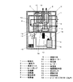
図1および図2に示すように、本実施形態の除湿装置は、吸気口1と排気口2を有する本体ケース3と、この本体ケース3内に設けられたヒートポンプ4とを備えている。このヒートポンプ4は、圧縮機5と、放熱器6、膨張手段7、吸熱器8とにより形成している。
(Embodiment 1)
As shown in FIGS. 1 and 2, the dehumidifying device of this embodiment includes a
送風手段9によって、吸気口1から本体ケース3内に吸気した空気は、放熱器6、吸熱器8を順次介して排気口2へと送風される。
The air sucked into the
送風手段9の風路であって放熱器6と吸熱器8の間には、回動自在に除湿ローター10を設けており、この除湿ローター10は放湿部11と吸湿部13を備えている。
A
放湿部11は放熱器6と吸熱器8の間の風路に、吸湿部13は吸熱器8と排気口2の間の風路に設けられており、放熱器6と放湿部11の間には加熱手段であるヒーター12を設けた構成としている。
The
すなわち、送風手段9によって吸気口1から本体ケース3内に吸気した空気は、放熱器6で加熱された後にヒーター12で更に加熱され、高温で相対湿度の低い空気となり、除湿ローター10の放湿部11へ送風される。
That is, the air sucked into the
この放湿部11に送風された空気は、放湿部11の湿気を取り込み湿度の高い状態となって吸熱器8へ送られる。この吸熱器8で結露させて除湿し、吸湿部13に達する。そこで、乾燥状態となった除湿ローター10の放湿部11が駆動手段16によって回転し、吸湿部13となり、この吸湿部13で吸熱器8で除湿されなかった湿度を吸湿し除湿する。
The air blown to the
本実施形態における特徴は、圧縮機5の異常を検知する異常検知制御手段であるオーバーロードプロテクター18を設け、更にこのオーバーロードプロテクター18の検知結果からヒーター12の運転を制御する制御手段17を設けたことである。
A feature of the present embodiment is that an
具体的には、オーバーロードプロテクター18は圧縮機5の天面に設けられ、この圧縮機5の温度によって圧縮機5の異常を検知する。この圧縮機5の異常とは、吸気口1に埃などが詰まり、放熱器6への送風が減少し、放熱器6での冷媒の冷却が抑制されると、圧縮機5が更に冷媒温度を上げようとするために、更に圧力が高くなる。これを繰り返すことにより圧縮機5が高圧、高温の状態になることを意味する。
Specifically, the
すなわち、オーバーロードプロテクター18は圧縮機5の天面における温度が設定されたしきい値以上の温度を検知するとヒートポンプ4を停止し、その検知結果から制御手段17によって、ヒーター12を同時に停止するものである。
That is, the
このように、ヒートポンプ4とヒーター12を同時に停止することにより、ヒートポンプ4の運転を停止している間、すなわち、除湿が効果的に行われない状態で、ヒーター12も停止することにより、除湿が効果的に行われない状態でのヒーター12による無駄な電力消費を無くし、更に安全性も高めることとなる。
Thus, by simultaneously stopping the
なお、設定されたしきい値の一例として、オーバーロードプロテクターの動作温度は約140〜150℃であり、復帰温度は約70℃である。 As an example of the set threshold value, the operating temperature of the overload protector is about 140 to 150 ° C., and the return temperature is about 70 ° C.
そして、制御手段17は、送風手段9による送風のみの運転を行う。圧縮機5の温度が、設定されたしきい値より低くなった場合、すなわち圧縮機5の異常が解消された場合に、最初にオーバーロードプロテクター18がヒートポンプ4を運転し、次に制御手段17がヒーター12を運転する。
And the control means 17 performs the driving | operation only of the ventilation by the ventilation means 9. FIG. When the temperature of the
具体的には、オーバーロードプロテクター18は圧縮機5の異常が解消された場合に、まずヒートポンプ4を運転する。そして圧縮機5が設定された所定期間正常運転を継続したことを確認し、その後制御手段17がヒーター12を運転するものである。
Specifically, the
このように、オーバーロードプロテクター18は圧縮機5の異常が解消された場合に、まずヒートポンプ4を運転し、次に制御手段17は圧縮機5が設定された所定期間正常運転を継続した後にヒーター12を運転することにより、確実に圧縮機5の異常が解消されたことを確認した上で、ヒーター12を運転することとなり、除湿が効果的に行われない状態でのヒーター12による不要な電力消費を無くし、更に安全性も高めることとなる。
As described above, when the abnormality of the
なお、設定された所定期間の一例は約5から10分である。 An example of the set predetermined period is about 5 to 10 minutes.
また、オーバーロードプロテクター18は圧縮機5の異常が解消された場合にヒートポンプ4を運転するが、制御手段17によって圧縮機5が所定期間正常運転を継続しないことを確認した場合には、ヒートポンプ4を再び停止させるものである。
The
具体的には、オーバーロードプロテクター18はヒートポンプ4の異常が解消された場合に、まずヒートポンプ4を運転する。そして制御手段17によって圧縮機5が所定期間正常運転を継続しないことを確認した場合、すなわち圧縮機5の温度が設定されたしきい値より再度高くなった場合には、オーバーロードプロテクター18はヒーター12を運転する前に再度ヒートポンプ4を停止させ、改めてヒートポンプ4の異常が解消されるまで、送風手段9による送風のみの運転を行うこととなる。
Specifically, the
このように、オーバーロードプロテクター18はヒートポンプ4の異常が解消されヒートポンプ4を運転するが、制御手段17によって圧縮機5が所定期間正常運転を継続しないことを確認した場合には、オーバーロードプロテクター18はヒートポンプ4を再度停止することとなり、確実にヒートポンプ4の異常が解消されたことを確認しないで、ヒーター12を運転することがないので、ヒーター12による無駄な電力消費を無くし、更に安全性も高めることとなる。
As described above, the
(実施の形態2)
実施の形態2は図3に示すように、実施の形態1に対し、制御手段17が異常検知制御手段であるオーバーロードプロテクター18の検知結果から加熱手段であるヒーター12に加え送風手段9の運転も制御する点と、機器異常ランプを設けた点が相違する。
(Embodiment 2)
As shown in FIG. 3, the second embodiment is different from the first embodiment in that the control means 17 operates the air blowing means 9 in addition to the
オーバーロードプロテクター18は圧縮機5の天面に設けられ、この圧縮機5の温度によって圧縮機5の異常を検知する。この圧縮機5の異常とは、吸気口1に埃などが詰まり、放熱器6への送風が減少し、放熱器6での冷媒の冷却が抑制されると、圧縮機5が更に冷媒温度を上げようとするために、更に圧力が高くなる。これを繰り返すことにより圧縮機5が高圧、高温の状態になることを意味する。
The
すなわち、オーバーロードプロテクター18が圧縮機5の天面の温度が設定されたしきい値以上の温度を検知すると、その検知結果から、オーバーロードプロテクター18がヒートポンプ4を停止し、制御手段17によってヒーター12を停止するものである。
That is, when the
そして、オーバーロードプロテクター18はヒートポンプ4の異常が解消された場合には、ヒートポンプ4を運転する。そして制御手段17は圧縮機5が設定された所定期間正常運転を継続したことを確認し、その後にヒーター12を運転するものである。一方、圧縮機5が所定期間正常運転を継続しない場合、再度、ヒートポンプ4を停止する停止サイクルを所定回数行った場合に送風手段9の運転も停止するものである。
The
停止サイクルとは具体的には以下の動作を意味する。まずオーバーロードプロテクター18は、ヒートポンプ4の異常が解消されるとヒートポンプ4を運転する。次に、制御手段17によって圧縮機5が所定期間正常運転を継続しないことを確認した場合、すなわち圧縮機5の温度が設定されたしきい値より再度高くなった場合には、ヒーター12を運転する前にオーバーロードプロテクター18は再度ヒートポンプ4を停止させる。そして送風手段9による送風のみの運転を行い、改めてヒートポンプ4の異常が解消されるのを待つサイクルである。
Specifically, the stop cycle means the following operation. First, the
このような、停止サイクルを設定された所定回数行った場合に送風手段9の運転を停止することにより、ヒーター12、ヒートポンプ4および送風手段9の運転を停止し、すなわち本体の運転を停止しすることとなる。
When such a stop cycle is performed a predetermined number of times, the operation of the air blowing means 9 is stopped, whereby the operation of the
具体的には、停止サイクルを設定された所定回数行った場合に、所定時間送風手段9を運転後に送風手段9の運転を停止するものである。 Specifically, when the stop cycle is performed a predetermined number of times, the operation of the air blowing means 9 is stopped after the air blowing means 9 is operated for a predetermined time.
このように、所定時間送風手段9を運転することにより、ヒートポンプ4を確実に冷却し、その後に送風手段9の運転を停止する、すなわち、本体の運転を停止させるので、ヒートポンプ4が異常になり易い状態で何度もヒートポンプ4の運転と停止を繰り返すことによる、無駄な電力消費を無くし、更に安全性も高めることとなる。
Thus, by operating the air blowing means 9 for a predetermined time, the
なお、設定された所定回数の一例は約3回である。 An example of the predetermined number of times set is about 3 times.
また、制御手段17は上記のように送風手段9の運転を停止した場合には、機器異常ランプ(図示せず)を点滅させることとなる。 Further, when the operation of the air blowing means 9 is stopped as described above, the control means 17 causes a device abnormality lamp (not shown) to blink.
このように、本体の運転が停止した場合に、機器異常ランプ(図示せず)を点滅させ、使用者に異常を知らせることにより、より安全性を高めることとなる。 As described above, when the operation of the main body is stopped, a device abnormality lamp (not shown) blinks to notify the user of the abnormality, thereby further improving safety.
以上のように本発明は、吸気口と排気口を有する本体ケースと、この本体ケース内に設けられたヒートポンプとを備え、このヒートポンプは、圧縮機と、圧縮機の下流に順次設けた放熱器、膨張手段、吸熱器とにより形成し、前記吸気口から前記本体ケース内に吸気した空気を前記放熱器、前記吸熱器を順次介して前記排気口へと送風する送風手段を設けるとともに、前記放熱器と前記吸熱器の間に回動自在に除湿ローターを設け、この除湿ローターは放湿部と吸湿部からなり、前記放湿部は前記放熱器と前記吸熱器の間の風路に設け、前記吸湿部は前記吸熱器と前記排気口の間の風路に設け、前記放熱器と前記放湿部の間に加熱手段を設けた構成とし、前記圧縮機の異常を検知し前記ヒートポンプを制御する異常検知制御手段と、この異常検知制御手段の検知結果から前記加熱手段の運転を制御する制御手段を設けたものであり、除湿が効果的に行われない状態での無駄な電力の消費を抑制し、更に安全性が高くなるものである。 As described above, the present invention includes a main body case having an intake port and an exhaust port, and a heat pump provided in the main body case. The heat pump includes a compressor and a radiator sequentially provided downstream of the compressor. And an expansion means, a heat absorber, and a blower means for blowing the air sucked into the main body case from the intake port to the exhaust port through the heat sink and the heat absorber in turn, and the heat dissipation A dehumidification rotor is provided between the heat sink and the heat absorber, and the dehumidification rotor includes a moisture release portion and a moisture absorption portion, and the moisture release portion is provided in an air path between the radiator and the heat absorber. The moisture absorption part is provided in an air passage between the heat absorber and the exhaust port, and a heating means is provided between the radiator and the moisture release part, and detects an abnormality of the compressor and controls the heat pump. Anomaly detection control means and the anomaly Control means for controlling the operation of the heating means from the detection result of the intelligent control means is provided, and wasteful power consumption in a state where dehumidification is not effectively performed is suppressed, and safety is further improved. Is.
すなわち、圧縮機の異常を検知する異常検知制御手段と、この異常検知制御手段の検知結果から加熱手段の運転を制御する制御手段を設けたので、圧縮機の異常を異常検知制御手段により検知することにより、ヒートポンプの運転を制御するとともに、加熱手段の運転も制御するので、結論として、除湿が効果的に行われない状態では、加熱手段の運転を停止することとなる。 That is, since the abnormality detection control means for detecting an abnormality of the compressor and the control means for controlling the operation of the heating means from the detection result of the abnormality detection control means are provided, the abnormality of the compressor is detected by the abnormality detection control means. As a result, the operation of the heat pump is controlled and the operation of the heating means is also controlled. As a result, the operation of the heating means is stopped in a state where dehumidification is not effectively performed.
これらの結果により、除湿が効果的に行われない状態での無駄な電力の消費抑制し、更に安全性が高くなるものである。 As a result of these, wasteful power consumption is suppressed in a state where dehumidification is not effectively performed, and safety is further improved.
従って、家庭用や事務所用などの、除湿装置として活用が期待されるものである。 Therefore, it is expected to be utilized as a dehumidifying device for home use or office use.
1 吸気口
2 排気口
3 本体ケース
4 ヒートポンプ
5 圧縮機
6 放熱器
7 膨張手段
8 吸熱器
9 送風手段
10 除湿ローター
11 放湿部
12 ヒーター
13 吸湿部
16 駆動手段
17 制御手段
18 オーバーロードプロテクター
DESCRIPTION OF
Claims (6)
Priority Applications (1)
| Application Number | Priority Date | Filing Date | Title |
|---|---|---|---|
| JP2008221386A JP5572931B2 (en) | 2008-08-29 | 2008-08-29 | Dehumidifier |
Applications Claiming Priority (1)
| Application Number | Priority Date | Filing Date | Title |
|---|---|---|---|
| JP2008221386A JP5572931B2 (en) | 2008-08-29 | 2008-08-29 | Dehumidifier |
Publications (2)
| Publication Number | Publication Date |
|---|---|
| JP2010051914A JP2010051914A (en) | 2010-03-11 |
| JP5572931B2 true JP5572931B2 (en) | 2014-08-20 |
Family
ID=42068405
Family Applications (1)
| Application Number | Title | Priority Date | Filing Date |
|---|---|---|---|
| JP2008221386A Expired - Fee Related JP5572931B2 (en) | 2008-08-29 | 2008-08-29 | Dehumidifier |
Country Status (1)
| Country | Link |
|---|---|
| JP (1) | JP5572931B2 (en) |
Families Citing this family (4)
| Publication number | Priority date | Publication date | Assignee | Title |
|---|---|---|---|---|
| JP5945688B2 (en) * | 2012-03-23 | 2016-07-05 | パナソニックIpマネジメント株式会社 | Dehumidifier |
| JP6074595B2 (en) * | 2013-01-29 | 2017-02-08 | パナソニックIpマネジメント株式会社 | Dehumidifier |
| JP6350186B2 (en) * | 2014-10-02 | 2018-07-04 | 三菱電機株式会社 | Dehumidifier |
| CN114992080B (en) * | 2022-06-01 | 2024-04-26 | 南京市水利规划设计院股份有限公司 | Water resource metering control device and control method thereof |
Family Cites Families (5)
| Publication number | Priority date | Publication date | Assignee | Title |
|---|---|---|---|---|
| JPH05126383A (en) * | 1991-11-07 | 1993-05-21 | Sharp Corp | Dehumidifier |
| JP3461067B2 (en) * | 1995-09-18 | 2003-10-27 | トキコ株式会社 | Air compressor |
| JP2005224768A (en) * | 2004-02-16 | 2005-08-25 | Kobe Steel Ltd | Air compressing apparatus |
| JP4591243B2 (en) * | 2005-07-07 | 2010-12-01 | パナソニック株式会社 | Dehumidifier |
| JP4665767B2 (en) * | 2006-01-10 | 2011-04-06 | パナソニック株式会社 | Dehumidifier |
-
2008
- 2008-08-29 JP JP2008221386A patent/JP5572931B2/en not_active Expired - Fee Related
Also Published As
| Publication number | Publication date |
|---|---|
| JP2010051914A (en) | 2010-03-11 |
Similar Documents
| Publication | Publication Date | Title |
|---|---|---|
| JP4169747B2 (en) | Air conditioner | |
| JP2010529398A5 (en) | ||
| KR100609840B1 (en) | Compressed air dryer for recycling heat by blower | |
| JP5572931B2 (en) | Dehumidifier | |
| JP6320777B2 (en) | Dehumidification system | |
| JP5686311B2 (en) | Gas removal system | |
| AU2015240421B2 (en) | Method and apparatus for controlling moisture | |
| JP4781886B2 (en) | Air conditioner | |
| CN106288067A (en) | A kind of solution dehumidifying air-conditioning system and structure thereof | |
| KR101295750B1 (en) | Compressed air dryer | |
| WO2012147153A1 (en) | Adsorption dehumidifier | |
| JP5217283B2 (en) | Dehumidifier | |
| JP2001190324A (en) | Humidity-absorbing type hair dryer | |
| JP5683838B2 (en) | Adsorption dehumidifier | |
| JP2006300364A (en) | Exhaust heat recovering and utilizing device and exhaust heat recovering and utilizing method for hot air ventilating dryer with sensible heat exchanger | |
| JP2006266607A (en) | Bathroom dryer | |
| JP4297847B2 (en) | Air conditioner | |
| JP5407489B2 (en) | Dehumidifier | |
| JP2009189970A (en) | Dehumidifying device | |
| JP2019120484A (en) | Dehumidifying air conditioner | |
| KR102698629B1 (en) | Hybrid Desiccant dryer Without Regeneration Exhaust | |
| JP5631148B2 (en) | Indoor dehumidifier | |
| JP5346707B2 (en) | Dehumidifier | |
| JP2018146172A (en) | Dehumidifier | |
| JP5262167B2 (en) | Dehumidifier |
Legal Events
| Date | Code | Title | Description |
|---|---|---|---|
| A621 | Written request for application examination |
Free format text: JAPANESE INTERMEDIATE CODE: A621 Effective date: 20110826 |
|
| RD01 | Notification of change of attorney |
Free format text: JAPANESE INTERMEDIATE CODE: A7421 Effective date: 20110913 |
|
| A977 | Report on retrieval |
Free format text: JAPANESE INTERMEDIATE CODE: A971007 Effective date: 20121122 |
|
| A131 | Notification of reasons for refusal |
Free format text: JAPANESE INTERMEDIATE CODE: A131 Effective date: 20121127 |
|
| RD01 | Notification of change of attorney |
Free format text: JAPANESE INTERMEDIATE CODE: A7421 Effective date: 20121214 |
|
| A521 | Written amendment |
Free format text: JAPANESE INTERMEDIATE CODE: A523 Effective date: 20130122 |
|
| A131 | Notification of reasons for refusal |
Free format text: JAPANESE INTERMEDIATE CODE: A131 Effective date: 20130820 |
|
| A521 | Written amendment |
Free format text: JAPANESE INTERMEDIATE CODE: A523 Effective date: 20131016 |
|
| RD01 | Notification of change of attorney |
Free format text: JAPANESE INTERMEDIATE CODE: A7421 Effective date: 20140107 |
|
| RD01 | Notification of change of attorney |
Free format text: JAPANESE INTERMEDIATE CODE: A7421 Effective date: 20140417 |
|
| TRDD | Decision of grant or rejection written | ||
| A01 | Written decision to grant a patent or to grant a registration (utility model) |
Free format text: JAPANESE INTERMEDIATE CODE: A01 Effective date: 20140603 |
|
| A61 | First payment of annual fees (during grant procedure) |
Free format text: JAPANESE INTERMEDIATE CODE: A61 Effective date: 20140616 |
|
| LAPS | Cancellation because of no payment of annual fees |