JP5568264B2 - Hanging bracket for square steel - Google Patents
Hanging bracket for square steel Download PDFInfo
- Publication number
- JP5568264B2 JP5568264B2 JP2009186449A JP2009186449A JP5568264B2 JP 5568264 B2 JP5568264 B2 JP 5568264B2 JP 2009186449 A JP2009186449 A JP 2009186449A JP 2009186449 A JP2009186449 A JP 2009186449A JP 5568264 B2 JP5568264 B2 JP 5568264B2
- Authority
- JP
- Japan
- Prior art keywords
- hanging bracket
- square steel
- bolt
- suspension
- insertion hole
- Prior art date
- Legal status (The legal status is an assumption and is not a legal conclusion. Google has not performed a legal analysis and makes no representation as to the accuracy of the status listed.)
- Active
Links
Images


Description
本願発明は、角形鋼用吊金具に関し、さらに詳しくは天井下地等を吊り下げるために用いられ、傾斜状態で使用される角形鋼にも付設可能な角形鋼用吊金具に関するものである。 The present invention relates to a hanging bracket for square steel, and more particularly to a hanging bracket for square steel that is used to suspend a ceiling base and the like and can be attached to a square steel used in an inclined state.
天井下地等を吊り下げるために用いられる吊金具としては、図12に示すように、C形鋼Y′のリップ部y′に引っかけて使用されるものが従来から多用されてきている。この吊金具X′の下端には、吊ボルト3′を取り付けるためのボルト支持部2′が形成されている。この場合、C形鋼Y′がリップ部y′を有しているので、吊金具X′の上端に形成された鉤状の係止部1′をリップ部y′に引っかけるだけでよく、しかも、吊ボルトを下げる位置を作用方向に自由に調節できるという利点もある。 As a hanging metal fitting used for suspending a ceiling base or the like, as shown in FIG. 12, one that is used by being hooked on a lip portion y ′ of a C-shaped steel Y ′ has been widely used. A bolt support 2 'for attaching a suspension bolt 3' is formed at the lower end of the suspension fitting X '. In this case, since the C-shaped steel Y 'has the lip portion y', it is only necessary to hook the hook-shaped locking portion 1 'formed at the upper end of the hanging bracket X' on the lip portion y '. There is also an advantage that the position for lowering the suspension bolt can be freely adjusted in the direction of action.
ところで、近年、C形鋼に代えて角形鋼(例えば、コーナ部で両端をかしめた角形鋼)が多用されるようになってきている。この角形鋼は、C形鋼に比べて捩れに対して強く、閉鎖断面なので強度が飛躍的に高まるし、軽量化や精度(例えば、平坦度)、コスト面でも有利となる。ところが、角形鋼の場合、吊金具を引っかける部分がないので、C形鋼用のものをそのまま使用することは不可能である。そこで、単純なL形形状の吊金具を使用する方法が考えられるが、L形形状の吊金具の場合、予め角形鋼の側面等にビス止めしておく必要があり、一旦取り付けると取付位置を変更することが不可能になるという不具合がある。 By the way, in recent years, square steel (for example, square steel in which both ends are caulked at a corner portion) has been frequently used instead of C-shaped steel. This square steel is more resistant to twisting than the C-shaped steel and has a closed cross section, so that the strength is dramatically increased, and is advantageous in terms of weight reduction, accuracy (for example, flatness) and cost. However, in the case of square steel, since there is no portion for hooking the hanging bracket, it is impossible to use the one for C-shaped steel as it is. Therefore, a method of using a simple L-shaped hanging bracket is conceivable. However, in the case of an L-shaped hanging bracket, it is necessary to screw it to the side surface of the square steel in advance, and once it is attached, the mounting position is changed. There is a problem that it is impossible to change.
この種の吊金具としては、角形鋼を抱持する抱持部をそれぞれ有する一対のハンガーにより構成されるものも既に提案されている(例えば、特許文献1参照)。 As this type of hanging metal fitting, one constituted by a pair of hangers each having a holding portion for holding a square steel has already been proposed (for example, see Patent Document 1).
ところが、上記特許文献1に開示されているハンガー装置の場合、抱持部をそれぞれ有する一対のハンガーにより構成されるところから、部品点数が多くなるとともに、組みつけ作業が複雑化し、コスト面でも不利となるという不具合がある。
However, in the case of the hanger device disclosed in the above-mentioned
本願発明は、上記の点に鑑みてなされたもので、構造が簡単で、組みつけ作業性にも優れた角形鋼用吊金具を提供することを目的としている。 The present invention has been made in view of the above points, and an object of the present invention is to provide a square steel hanger having a simple structure and excellent workability.
本願発明では、上記課題を解決するための第1の手段として、断面四角形形状の角形鋼に対して直交する方向から嵌め合わせられる断面コ字状の吊金具本体と、該吊金具本体の一端に対して取付角度を変更可能に取り付けられ且つ吊ボルトが取り付けられるボルト支持部とによって構成した角形鋼用吊金具において、前記吊金具本体の一端には、断面コ字状に隆起された嵌挿穴を有する隆起部を一体に形成する一方、前記ボルト支持部を、前記吊ボルトを取り付けた水平部と止着子を挿通するための挿通穴を形成した垂直部とからなる断面L字状とし、前記挿通穴と前記嵌挿穴とに前記止着子を嵌挿して固定している。 In the present invention, as a first means for solving the above-mentioned problems, a suspension metal fitting body having a U-shaped cross section that is fitted from a direction orthogonal to a square steel having a square sectional shape, and one end of the suspension fitting main body. In the bracket for square steel, which is configured by a bolt support portion to which the mounting angle can be changed and a suspension bolt is attached , and at one end of the suspension bracket main body, the fitting insertion raised in a U-shaped cross section While forming the bulge part which has a hole integrally, the said bolt support part is made into the cross-section L character shape which consists of the horizontal part which attached the said suspension bolt, and the vertical part which formed the penetration hole for inserting a fastener. The fastening element is inserted and fixed in the insertion hole and the insertion hole .
上記のように構成したことにより、断面四角形形状の角形鋼に対して直交する方向から吊金具本体を嵌め合わせるだけで吊金具本体をセットすることができるとともに、セットされた吊金具本体を角形鋼に沿って容易に移動できるところから、構成が簡略化されるとともに、吊ボルトによって吊り下げられる下地材の吊り下げ位置に容易に位置調節することができる。しかも、吊ボルトが取り付けられるボルト支持部を、吊金具本体の一端に対して取付角度を変更可能に取り付けることが可能となっているので、傾斜状態で使用される角形鋼に付設した場合であっても、吊ボルトを鉛直姿勢とすることが容易に可能となる。また、吊金具本体の一端に、断面コ字状に隆起された嵌挿穴を有する隆起部を一体に形成する一方、前記ボルト支持部を、前記吊ボルトを取り付けた水平部と止着子を挿通するための挿通穴を形成した垂直部とからなる断面L字状とし、前記挿通穴と前記嵌挿穴とに前記止着子を嵌挿して固定するようにしているので、前記吊金具本体の一端に前記ボルト支持部を強固に固定することができる。さらに、吊金具本体の一端に、断面コ字状に隆起された嵌挿穴を有する隆起部を一体に形成するようにしているので、隆起部と角形鋼の側面との間に隙間が形成されることとなり、該隙間を止着子を固定する時の作業用隙間として利用することができる。 By configuring as described above, the hanging bracket main body can be set only by fitting the hanging bracket main body from the direction orthogonal to the square steel having a rectangular cross section, and the set hanging bracket main body is square steel. Since the structure can be simplified, the position can be easily adjusted to the suspension position of the base material suspended by the suspension bolt. In addition, since the bolt support part to which the suspension bolt is attached can be attached to one end of the suspension fitting body so that the attachment angle can be changed, this is the case where it is attached to the square steel used in an inclined state. However, the suspension bolt can be easily set to the vertical posture. In addition, a raised portion having a fitting insertion hole raised in a U-shaped cross section is integrally formed at one end of the hanging bracket main body, while the bolt support portion is provided with a horizontal portion and a fastening member attached with the hanging bolt. Since the cross section is formed in an L shape with a vertical portion in which an insertion hole for insertion is formed, and the fastening element is fitted and fixed to the insertion hole and the fitting insertion hole, the suspension metal fitting body The bolt support part can be firmly fixed to one end of the. Furthermore, since a raised portion having a fitting insertion hole raised in a U-shaped cross section is integrally formed at one end of the hanging metal fitting body, a gap is formed between the raised portion and the side surface of the square steel. Therefore, the gap can be used as a working gap when fixing the stationary element.
本願発明の第1の手段によれば、断面四角形形状の角形鋼に対して直交する方向から嵌め合わせられる断面コ字状の吊金具本体と、該吊金具本体の一端に対して取付角度を変更可能に取り付けられ且つ吊ボルトが取り付けられるボルト支持部とによって構成して、角形鋼に対して直交する方向から吊金具本体を嵌め合わせるだけで吊金具本体をセットすることができるとともに、セットされた吊金具本体を角形鋼に沿って容易に移動できるようにしたので、構成が簡略化されるとともに、吊ボルトによって吊り下げられる下地材の吊り下げ位置を容易に位置調節することができるという効果がある。しかも、吊ボルトが取り付けられるボルト支持部を、吊金具本体の一端に対して取付角度を変更可能に取り付けることが可能となっているので、傾斜状態で使用される角形鋼に付設した場合であっても、吊ボルトを鉛直姿勢とすることが容易に可能となるという効果もある。また、吊金具本体の一端に、断面コ字状に隆起された嵌挿穴を有する隆起部を一体に形成する一方、前記ボルト支持部を、前記吊ボルトを取り付けた水平部と止着子を挿通するための挿通穴を形成した垂直部とからなる断面L字状とし、前記挿通穴と前記嵌挿穴とに前記止着子を嵌挿して固定するようにしているので、前記吊金具本体の一端に前記ボルト支持部を強固に固定することができるという効果もある。さらに、吊金具本体の一端に、断面コ字状に隆起された嵌挿穴を有する隆起部を一体に形成するようにしているので、隆起部と角形鋼の側面との間に隙間が形成されることとなり、該隙間を止着子を固定する時の作業用隙間として利用することができるという効果もある。 According to the first means of the present invention, the hanging metal fitting body having a U-shaped cross-section that is fitted from a direction orthogonal to the square steel having a square cross-sectional shape, and the mounting angle is changed with respect to one end of the hanging fitting main body. It is possible to set the hanging bracket body by simply fitting the hanging bracket body from the direction orthogonal to the square steel. Since the suspension metal fitting body can be easily moved along the square steel, the structure is simplified and the suspension position of the base material suspended by the suspension bolt can be easily adjusted. is there. In addition, since the bolt support part to which the suspension bolt is attached can be attached to one end of the suspension fitting body so that the attachment angle can be changed, this is the case where it is attached to the square steel used in an inclined state. However, there is also an effect that the suspension bolt can be easily set in the vertical posture. In addition, a raised portion having a fitting insertion hole raised in a U-shaped cross section is integrally formed at one end of the hanging bracket main body, while the bolt support portion is provided with a horizontal portion and a fastening member attached with the hanging bolt. Since the cross section is formed in an L shape with a vertical portion in which an insertion hole for insertion is formed, and the fastening element is fitted and fixed to the insertion hole and the fitting insertion hole, the suspension metal fitting body There is also an effect that the bolt support portion can be firmly fixed to one end of the bolt. Furthermore, since a raised portion having a fitting insertion hole raised in a U-shaped cross section is integrally formed at one end of the hanging metal fitting body, a gap is formed between the raised portion and the side surface of the square steel. In other words, the gap can be used as a working gap when fixing the fastening element.
以下、添付の図面を参照して、本願発明の幾つかの実施の形態および参考例について説明する。 Hereinafter, some embodiments and reference examples of the present invention will be described with reference to the accompanying drawings.
第1の実施の形態
図1には、本願発明の第1の実施の形態にかかる角形鋼用吊金具が示されている。
First Embodiment FIG. 1 shows a hanging bracket for square steel according to a first embodiment of the present invention.
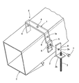
この角形鋼用吊金具Xは、断面四角形形状の角形鋼Yに対して直交する方向から嵌め合わせられる断面コ字状の吊金具本体1と、該吊金具本体1の一端1aに対して取付角度を変更可能に取り付けられ且つ吊ボルト3が取り付けられるボルト支持部2とによって構成されている。符号4は吊金具本体1を角形鋼Yに固定するためのビスである。
This square steel hanging bracket X has a U-shaped
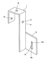
前記吊金具本体1の一端1aには、断面コ字状に隆起された隆起部5が一体に形成されており、該隆起部5には、嵌挿穴6が形成されている。そして、前記吊金具本体1における隆起部5に対して前記ボルト支持部2が止着子であるリベット7を介して結合されることとなっている。
A raised
また、前記ボルト支持部2は、断面L字状とされており、その垂直部2aには、前記リベット7を挿通するための挿通穴8が形成され、その水平部2bには、前記吊ボルト3が取り付けられることとなっている。
The
上記のように構成したことにより、本実施の形態にかかる角形鋼用吊金具Xは、次のようにして取り付けられる。 By having comprised as mentioned above, the square metal hanging bracket X concerning this Embodiment is attached as follows.
断面四角形形状の角形鋼Yに対して直交する方向から吊金具本体1を嵌め合わせ、吊ボルト3によって吊り下げられる下地材の吊り下げ位置に位置調節した後に、ビス4によって吊金具本体1を角形鋼Yに対して固定する。
After fitting the suspension
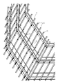
この吊金具Xは、図4に示すように、工場の電気又は設備のメンテナンスのために人が上に乗って尚且つ天井下地を吊り下げた荷重が持てるように考案された「ぶどう棚」と呼ばれる下地組に好適に使用されるが、この場合、角形鋼Yは水平に対して角度θだけ傾斜した状態となる。そこで、吊ボルト3を鉛直姿勢とした状態で、吊金具本体1の隆起部5に形成された嵌挿穴6とボルト支持部2の垂直部2aに形成された挿通穴8とを一致させ、その状態で、前記挿通穴8と嵌挿穴6とにリベット7を嵌挿してカシメると、吊金具本体1の一端1aに対してボルト支持部2を強固に固定することができる。図4において、符号9は角形鋼Yを上方の鋼材(例えば、H形鋼)に吊り下げるためのボルトである。
As shown in FIG. 4, the hanging bracket X is a “vine shelf” designed to allow a person to get on and load the ceiling underhang for maintenance of factory electricity or equipment. In this case, the square steel Y is inclined by an angle θ with respect to the horizontal. Therefore, in a state where the
上記したように、本実施の形態によれば、角形鋼Yに対して直交する方向から吊金具本体1を嵌め合わせるだけで吊金具本体1をセットすることができるとともに、セットされた吊金具本体1を角形鋼Yに沿って容易に移動できるようにしたので、構成が簡略化されるとともに、吊ボルト3によって吊り下げられる下地材の吊り下げ位置を容易に位置調節することができる。しかも、吊ボルト3が取り付けられるボルト支持部2を、吊金具本体1の一端に対して取付角度を変更可能に取り付けることが可能となっているので、傾斜状態で使用される角形鋼Yに付設した場合であっても、吊ボルト3を鉛直姿勢とすることが容易に可能となる。また、吊金具本体1の一端1aに対してボルト支持部2をリベット7を介して結合するようにしているので、吊金具本体1の一端1aとボルト支持部2との結合状態が堅固となる。なお、この場合、隆起部5と角形鋼Yの側面との間に形成される隙間は、リベット7をカシメる時の作業を容易にする。
As described above, according to the present embodiment, the hanging
この角形鋼用吊金具Xは、水平配置された角形鋼Yに対しても適用可能であることは勿論である。 Needless to say, this square steel hanging bracket X can also be applied to a horizontally disposed square steel Y.
第2の実施の形態
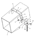
図2には、本願発明の第2の実施の形態にかかる角形鋼用吊金具が示されている。
Second Embodiment FIG. 2 shows a hanging bracket for square steel according to a second embodiment of the present invention.
この場合、吊金具本体1の一端1aとボルト支持部2とは、止着子であるボルト10およびナット11により結合されることとなっている。つまり、吊金具本体1の隆起部5に形成された嵌挿穴6とボルト支持部2の垂直部2aに形成された挿通穴8とを一致させ、その状態で、前記挿通穴8と嵌挿穴6とにボルト10を嵌挿しつつ該ボルト10の先端にナット11を螺着させることにより、吊金具本体1の一端1aに対してボルト支持部2を固定することができるようになっているのである。なお、この場合、ナット11は隆起部5における嵌挿穴6の裏側口縁に予じめ固定しておいてもよいし、ナットを用いることなく、隆起部5の嵌挿穴6を、バーリング加工したネジ穴とし、ボルト10を嵌挿穴6に直接螺合するようにしてもよい。
In this case, the one
その他の構成および作用効果は、第1の実施の形態におけると同様なので、説明を省略する。 Other configurations and operational effects are the same as those in the first embodiment, and thus description thereof is omitted.
第1の参考例
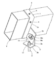
図3には、本願発明の第1の参考例にかかる角形鋼用吊金具が示されている。
The first reference example 3, the first hanging bracket for such square steel in Reference Example of the present invention is shown.
この場合、吊金具本体1の一端1aには、ネジ棒12が立設されており、該ネジ棒12をボルト支持部2の垂直部2aに形成された挿通穴8に挿通し、該ネジ棒12の端部にナット13を螺着することにより、吊金具本体1の一端1aに対してボルト支持部2を固定することができるようになっている。この場合、第1および第2の実施の形態における隆起部5は省略されるので、吊金具本体1の構成が、より簡略化される。
In this case, a threaded
その他の構成および作用効果は、第1の実施の形態におけると同様なので、説明を省略する。 Other configurations and operational effects are the same as those in the first embodiment, and thus description thereof is omitted.
第2の参考例
図5ないし図8には、本願発明の第2の参考例にかかる角形鋼用吊金具が示されている。
Second Reference Example FIGS. 5 to 8 show a square steel hanging bracket according to a second reference example of the present invention.
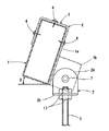
この吊金具Xは、図9に示すように、角形鋼Yを母屋材として使用した場合に使用されるものである。この場合、母屋の勾配がθであるところから、吊ボルト3を鉛直姿勢で取り付けるためには、吊ボルト3が取り付けられるボルト支持部2を、吊金具本体1の一端に対して取付角度を変更可能に取り付けることが必要となる。
This hanging bracket X is used when square steel Y is used as a purlin as shown in FIG. In this case, in order to attach the
そこで、この角形鋼用吊金具Xは、図5ないし図8に示すように、一端1aから直角方向に一体に突設された支持部1bを備えた吊金具本体1と、前記支持部1bに対して揺動自在に支持されるボルト支持部2とからなっている。該ボルト支持部2は、断面L字状とされており、その水平部2bには、前記吊ボルト3が取り付けられることとなっている。
Therefore, as shown in FIGS. 5 to 8, the rectangular steel hanging bracket X includes a hanging bracket
前記支持部1bには、上下方向に延びる(例えば、吊金具本体1の側面と平行に延びる)スリット部14aと該スリット部14aの下端に連続する円弧部14bとからなる係合穴14が形成されている。ここで、前記スリット部14aの幅寸法は、後述する係合凸片15が挿入できるように、前記ボルト支持部2における垂直部2aの板厚より若干大きくされている。
An
一方、前記ボルト支持部2における垂直部2aには、前記係合穴14におけるスリット部14aから挿入され、前記円弧部14bにおいて揺動自在に係合される係合凸片15が直角方向に形成されている。
On the other hand, on the
前記係合凸片15は、前記垂直部2aの一部を直角に切り起こしてなり、前記円弧部14bの口縁に係合する係合部15aと該係合部15aの先端に一体に形成され且つ幅寸法が前記円弧部14bより大きく前記スリット部14aより短い形状とされた抜け止め部15bとによって構成されている。ここで、係合部15aの幅寸法は、前記円弧部14bにおいて係合部15aが回転できるように、該円弧部14bの内径と同径あるいは該内径より若干小さくされている。符号16は係合凸片1を切り起こした跡に形成された開口である。
The engaging
図面中、符号17は吊ボルト3をボルト支持部2の水平部2bに取り付けるためのナット、18はボルト挿通穴、19はビス4を挿通させる穴である。
In the drawings,
上記のように構成したことにより、吊金具本体1の支持部1bに形成された係合穴14におけるスリット部14aからボルト支持部2の垂直部2aに形成された係合凸片15を挿入し、該係合凸片15を前記係合穴14の円弧部14aにおいて90°回転させると、係合凸片15の係合部15aが円弧部14aに係合するとともに抜け止め部14bによって脱落が防止されることとなり、吊ボルト3を鉛直姿勢で保持した状態で前記吊金具本体1の支持部1bに対してボルト支持部2を揺動自在に支持することができる。つまり、吊金具本体1が固定される部材(例えば、角形鋼Y)の形状にかかわらず、吊ボルト3を常時鉛直姿勢で支持することができるのである。
By configuring as described above, the
しかも、係合凸片15は、ボルト支持部2における垂直部2aの一部を直角に切り起こして形成されることとなっているので、簡略な構造となり、低コストで製作できる。
In addition, the engaging
なお、本参考例においては、支持部1bが吊金具本体1の一端1aに対して一体に形成されるようになっているが、支持部1bを、吊金具本体1とは別体に形成し、吊金具本体1に対して各種の結合手段により取り付ける構成とすることもできる。また、ボルト支持部2の水平部2bに対する吊ボルト3の取付構造としては、第3の参考例の他にバーリング加工により形成した肉盛り部にネジ切りして吊ボルト3を螺着した後、水平部2bの上側あるいは下側にナット17を螺着する構造を採用することもできる。
In this reference example , the
第3の参考例
図10および図11には、本願発明の第3の参考例にかかる角形鋼用吊金具が示されている。
Third Reference Example FIGS. 10 and 11 show a square steel hanging bracket according to a third reference example of the present invention.
この吊金具Xも、図9に示すように、角形鋼Yを母屋材として使用した場合に使用されるものである。この場合も、母屋の勾配がθであるところから、吊ボルト3を鉛直姿勢で取り付けるためには、吊ボルト3が取り付けられるボルト支持部2を、吊金具本体1の一端に対して取付角度を変更可能に取り付けることが必要となる。
This hanging bracket X is also used when square steel Y is used as a purlin as shown in FIG. Also in this case, in order to attach the
この場合、この角形鋼用吊金具Xは、図10および図11に示すように、一端1aから直角方向に一体に突設された支持部1bを備えた吊金具本体1と、前記支持部1bに対して揺動自在に支持されるボルト支持部2とからなっている。該ボルト支持部2は、断面L字状とされており、その水平部2bには、前記吊ボルト3が取り付けられることとなっている。
In this case, as shown in FIGS. 10 and 11, the rectangular steel hanging bracket X includes a hanging bracket
そして、前記吊金具本体1の一端1aに形成された支持部1bには、嵌挿穴6が形成されており、前記支持部1bに対して前記ボルト支持部2がリベット7を介して結合されることとなっている。
An
この場合、吊ボルト3を鉛直姿勢とした状態で、吊金具本体1の一端1aに形成された支持部1bに形成された嵌挿穴6とボルト支持部2の垂直部2aに形成された挿通穴8とを一致させ、その状態で、前記挿通穴8と嵌挿穴6とにリベット7を嵌挿してカシメると、吊金具本体1の一端1aに対してボルト支持部2を強固に固定することができる。
In this case, in a state where the
なお、リベット7に代えて、第1の参考例におけると同様に、ボルトとナットとを用いてボルト支持部2を吊金具本体1に取り付けるようにしてもよい。また、この場合においても、支持部1bを、吊金具本体1とは別体に形成し、吊金具本体1に対して各種の結合手段により取り付ける構成とすることもできる。
Instead of the
その他の構成および作用効果は、第1の実施の形態および第2の参考例におけると同様なので、説明を省略する。 Other configurations and operational effects are the same as those in the first embodiment and the second reference example , and thus description thereof is omitted.
本願発明は、上記各実施の形態に限定されるものではなく、発明の要旨を逸脱しない範囲において適宜設計変更可能なことは勿論である。 The invention of the present application is not limited to the above-described embodiments, and it goes without saying that the design can be changed as appropriate without departing from the scope of the invention.
1は吊金具本体
1aは一端
2はボルト支持部
2aは垂直部
2bは水平部
3は吊ボルト
5は隆起部
6は嵌挿穴
7は止着子(リベット)
10は止着子(ボルト)
Xは吊金具
Yは角形鋼
1 is a hanging
2a is vertical part
2b is
5 is a raised part
6 is the insertion hole
7 is an anchor (rivet)
10 is a fastener (bolt)
X is hanging bracket Y is square steel
Claims (1)
Priority Applications (1)
| Application Number | Priority Date | Filing Date | Title |
|---|---|---|---|
| JP2009186449A JP5568264B2 (en) | 2009-08-11 | 2009-08-11 | Hanging bracket for square steel |
Applications Claiming Priority (1)
| Application Number | Priority Date | Filing Date | Title |
|---|---|---|---|
| JP2009186449A JP5568264B2 (en) | 2009-08-11 | 2009-08-11 | Hanging bracket for square steel |
Publications (3)
| Publication Number | Publication Date |
|---|---|
| JP2011038314A JP2011038314A (en) | 2011-02-24 |
| JP2011038314A5 JP2011038314A5 (en) | 2012-08-09 |
| JP5568264B2 true JP5568264B2 (en) | 2014-08-06 |
Family
ID=43766343
Family Applications (1)
| Application Number | Title | Priority Date | Filing Date |
|---|---|---|---|
| JP2009186449A Active JP5568264B2 (en) | 2009-08-11 | 2009-08-11 | Hanging bracket for square steel |
Country Status (1)
| Country | Link |
|---|---|
| JP (1) | JP5568264B2 (en) |
Families Citing this family (2)
| Publication number | Priority date | Publication date | Assignee | Title |
|---|---|---|---|---|
| JP6135912B2 (en) * | 2013-03-22 | 2017-05-31 | 株式会社大林組 | Ceiling foundation hardware and ceiling structure |
| CN108706437A (en) * | 2018-08-13 | 2018-10-26 | 大连洁能重工股份有限公司 | A kind of steel structure support mounting hanger |
Family Cites Families (5)
| Publication number | Priority date | Publication date | Assignee | Title |
|---|---|---|---|---|
| JP3189718B2 (en) * | 1996-12-25 | 2001-07-16 | 松下電工株式会社 | Suspension member support |
| JP3817344B2 (en) * | 1997-07-24 | 2006-09-06 | 株式会社サワタ建材社 | Hanger for ceiling edge receiving suspension |
| JP3817346B2 (en) * | 1997-08-19 | 2006-09-06 | 株式会社サワタ建材社 | Ceiling hanging bolt connection bracket |
| JP2003293513A (en) * | 2002-04-03 | 2003-10-15 | Sato Katako Seisakusho:Kk | Suspension bolt supporting device |
| JP2006328752A (en) * | 2005-05-25 | 2006-12-07 | Sawata Kenzaisha:Kk | Ceiling material mounting device |
-
2009
- 2009-08-11 JP JP2009186449A patent/JP5568264B2/en active Active
Also Published As
| Publication number | Publication date |
|---|---|
| JP2011038314A (en) | 2011-02-24 |
Similar Documents
| Publication | Publication Date | Title |
|---|---|---|
| US9096998B2 (en) | Ceiling system with ceiling element mounting brackets | |
| US20130214098A1 (en) | Top beam clamp | |
| AU2015391344B2 (en) | Support for fastening façade elements | |
| JP5460072B2 (en) | Hanging bracket for square steel | |
| JP6103902B2 (en) | Suspension bracket for ceiling base | |
| JP5568264B2 (en) | Hanging bracket for square steel | |
| JP5392462B2 (en) | Fixing bracket for reinforcing brace for ceiling and fixing structure | |
| JP4165894B2 (en) | Cable holder for suspension bolts | |
| AU2018212423B2 (en) | Support for fastening facade elements | |
| JP3180375U (en) | Seismic bracket with hanging bolts attached to C-shaped steel | |
| JP5181270B2 (en) | Mounting bracket for base material for steady rest | |
| US7243891B2 (en) | Mounting bracket, and method therefor | |
| JP5455699B2 (en) | Auxiliary tool for hanging bracket | |
| JP4255407B2 (en) | 取 付 け Mounting structure | |
| JP5038677B2 (en) | Brace mounting structure | |
| US10605403B2 (en) | Cantilevered screwless hanger | |
| JP7168978B2 (en) | Suspension bolt fixture | |
| JP5486200B2 (en) | Bathroom suspension stand | |
| JP6099178B1 (en) | Ceiling clip | |
| JP6945359B2 (en) | Panel body | |
| JP5997935B2 (en) | Hanging bracket for square steel | |
| JP6906344B2 (en) | Furnace mounting bracket | |
| JP6617932B2 (en) | External wall height adjustment structure | |
| JP7058079B2 (en) | Exterior wall repair structure | |
| US9068688B2 (en) | Hanging systems |
Legal Events
| Date | Code | Title | Description |
|---|---|---|---|
| RD02 | Notification of acceptance of power of attorney |
Free format text: JAPANESE INTERMEDIATE CODE: A7422 Effective date: 20111220 |
|
| A521 | Request for written amendment filed |
Free format text: JAPANESE INTERMEDIATE CODE: A523 Effective date: 20120625 |
|
| A621 | Written request for application examination |
Free format text: JAPANESE INTERMEDIATE CODE: A621 Effective date: 20120625 |
|
| A977 | Report on retrieval |
Free format text: JAPANESE INTERMEDIATE CODE: A971007 Effective date: 20130709 |
|
| A131 | Notification of reasons for refusal |
Free format text: JAPANESE INTERMEDIATE CODE: A131 Effective date: 20130730 |
|
| A521 | Request for written amendment filed |
Free format text: JAPANESE INTERMEDIATE CODE: A523 Effective date: 20130910 |
|
| TRDD | Decision of grant or rejection written | ||
| A01 | Written decision to grant a patent or to grant a registration (utility model) |
Free format text: JAPANESE INTERMEDIATE CODE: A01 Effective date: 20140617 |
|
| A61 | First payment of annual fees (during grant procedure) |
Free format text: JAPANESE INTERMEDIATE CODE: A61 Effective date: 20140623 |
|
| R150 | Certificate of patent or registration of utility model |
Ref document number: 5568264 Country of ref document: JP Free format text: JAPANESE INTERMEDIATE CODE: R150 |
|
| R250 | Receipt of annual fees |
Free format text: JAPANESE INTERMEDIATE CODE: R250 |
|
| R250 | Receipt of annual fees |
Free format text: JAPANESE INTERMEDIATE CODE: R250 |
|
| R250 | Receipt of annual fees |
Free format text: JAPANESE INTERMEDIATE CODE: R250 |