JP5568261B2 - Rolling mill and tandem rolling mill equipped with the rolling mill - Google Patents
Rolling mill and tandem rolling mill equipped with the rolling mill Download PDFInfo
- Publication number
- JP5568261B2 JP5568261B2 JP2009170815A JP2009170815A JP5568261B2 JP 5568261 B2 JP5568261 B2 JP 5568261B2 JP 2009170815 A JP2009170815 A JP 2009170815A JP 2009170815 A JP2009170815 A JP 2009170815A JP 5568261 B2 JP5568261 B2 JP 5568261B2
- Authority
- JP
- Japan
- Prior art keywords
- roll
- work roll
- rolling mill
- work
- minimum diameter
- Prior art date
- Legal status (The legal status is an assumption and is not a legal conclusion. Google has not performed a legal analysis and makes no representation as to the accuracy of the status listed.)
- Active
Links
Images


Classifications
-
- B—PERFORMING OPERATIONS; TRANSPORTING
- B21—MECHANICAL METAL-WORKING WITHOUT ESSENTIALLY REMOVING MATERIAL; PUNCHING METAL
- B21B—ROLLING OF METAL
- B21B27/00—Rolls, roll alloys or roll fabrication; Lubricating, cooling or heating rolls while in use
- B21B27/02—Shape or construction of rolls
- B21B27/021—Rolls for sheets or strips
-
- B—PERFORMING OPERATIONS; TRANSPORTING
- B21—MECHANICAL METAL-WORKING WITHOUT ESSENTIALLY REMOVING MATERIAL; PUNCHING METAL
- B21B—ROLLING OF METAL
- B21B13/00—Metal-rolling stands, i.e. an assembly composed of a stand frame, rolls, and accessories
- B21B13/14—Metal-rolling stands, i.e. an assembly composed of a stand frame, rolls, and accessories having counter-pressure devices acting on rolls to inhibit deflection of same under load; Back-up rolls
-
- B—PERFORMING OPERATIONS; TRANSPORTING
- B21—MECHANICAL METAL-WORKING WITHOUT ESSENTIALLY REMOVING MATERIAL; PUNCHING METAL
- B21B—ROLLING OF METAL
- B21B13/00—Metal-rolling stands, i.e. an assembly composed of a stand frame, rolls, and accessories
- B21B13/02—Metal-rolling stands, i.e. an assembly composed of a stand frame, rolls, and accessories with axes of rolls arranged horizontally
- B21B2013/025—Quarto, four-high stands
-
- B—PERFORMING OPERATIONS; TRANSPORTING
- B21—MECHANICAL METAL-WORKING WITHOUT ESSENTIALLY REMOVING MATERIAL; PUNCHING METAL
- B21B—ROLLING OF METAL
- B21B13/00—Metal-rolling stands, i.e. an assembly composed of a stand frame, rolls, and accessories
- B21B13/02—Metal-rolling stands, i.e. an assembly composed of a stand frame, rolls, and accessories with axes of rolls arranged horizontally
- B21B2013/028—Sixto, six-high stands
-
- B—PERFORMING OPERATIONS; TRANSPORTING
- B21—MECHANICAL METAL-WORKING WITHOUT ESSENTIALLY REMOVING MATERIAL; PUNCHING METAL
- B21B—ROLLING OF METAL
- B21B2267/00—Roll parameters
- B21B2267/02—Roll dimensions
- B21B2267/06—Roll diameter
Description
本発明は、作業ロールの小径化が図れる圧延機及びそれを備えたタンデム圧延機に関する。 The present invention relates to a rolling mill capable of reducing the diameter of a work roll and a tandem rolling mill equipped with the rolling mill.
従来の所謂中間ロール駆動の6段式の圧延機(以下6段ミルと称す)において、作業ロール径の最小値は、当該作業ロールの圧延可能な板幅内,外にサポート(支持)ロールが無い場合、中間ロール駆動の接線力に耐える作業ロールたわみ剛性値により決まる。例えば、非特許文献1によると、4幅材(4feet)、中間ロール駆動でφ180〜φ380となっている。
In a conventional so-called intermediate roll-driven 6-stage rolling mill (hereinafter referred to as a 6-stage mill), the minimum value of the work roll diameter is a support (support) roll inside and outside the roll width of the work roll. Otherwise, it is determined by the work roll deflection rigidity value that can withstand the tangential force of the intermediate roll drive. For example, according to Non-Patent
ここで作業ロール駆動の場合、前記接線力は働かないが、圧延機入、出側の差張力が働く。従って、駆動系の許容強度の範囲において、作業ロール径の最小値は、前記差張力に耐える作業ロールたわみ剛性値により決まり、少なくとも前記と同等の作業ロール径が可能となる。また、作業ロール駆動の場合、4段式の圧延機(以下4段ミルと称す)においても、この観点において少なくとも前記と同等の作業ロール径が可能となる。 Here, in the case of the work roll drive, the tangential force does not work, but the differential tension on the entry and exit sides of the rolling mill works. Therefore, the minimum value of the work roll diameter within the allowable strength range of the drive system is determined by the work roll deflection rigidity value that can withstand the differential tension, and at least a work roll diameter equivalent to that described above is possible. Further, in the case of work roll driving, even in a four-stage rolling mill (hereinafter referred to as a four-stage mill), at least a work roll diameter equivalent to the above can be achieved from this viewpoint.
また、6段ミルとしては、従来、作業ロールの圧延可能な板幅内にサポートロールを有するものもあり、さらには、作業ロールの圧延可能な板幅外に支持ベアリングを設け、この支持ベアリングを介して作業ロールに水平曲げを加えるものが特許文献1で開示されている。
Further, as a six-stage mill, there is a conventional one having a support roll within the roll width of the work roll, and further provided with a support bearing outside the roll width of the work roll.
ところで、最近の需要に対応するため、より硬いステンレス鋼等の特殊鋼を、作業ロールの圧延可能な板幅内にサポートロールを有しない6段ミルや4段ミルで圧延しようとすると、前述した作業ロール径では、大き過ぎ、荷重が高く、必要な圧下量がとれないという問題や光沢不良等の問題があった。 By the way, in order to meet the recent demand, when trying to roll a harder special steel such as stainless steel by a 6-stage mill or a 4-stage mill that does not have a support roll within the width of the work roll that can be rolled, it is described above. There was a problem that the work roll diameter was too large, the load was high, and a necessary reduction amount could not be obtained, and there were problems such as poor gloss.
一方、作業ロールの圧延可能な板幅内にサポートロールを有する6段ミルや4段ミルは、サポートロール部のスペースが少なく、十分な強度及び剛性確保が難しく、また、作業ロールの圧延可能な板幅内にサポートロールを支持するサポートベアリングが有るため、材料によってはそのサポートベアリングのマークがサポートロール及び作業ロールを介して板に転写・発生するという問題があった。 On the other hand, a 6-stage mill or a 4-stage mill having a support roll within the roll width of the work roll has a small space for the support roll, and it is difficult to ensure sufficient strength and rigidity, and the work roll can be rolled. Since there is a support bearing for supporting the support roll within the width of the plate, depending on the material, there is a problem that the mark of the support bearing is transferred and generated on the plate via the support roll and the work roll.
また、作業ロールの圧延可能な板幅外に支持ベアリングを設けた圧延機は、いずれも上下同位相の支持ベアリングのため、サイズの大きなベアリングが使用できず、大きな水平力が生じる高荷重、高トルクの硬質材の圧延には採用することができないという問題があった。 In addition, all rolling mills with support bearings outside the roll width of the work roll that can be rolled are support bearings that are in the same phase in the top and bottom, so large bearings cannot be used, and high loads and high loads that generate large horizontal forces. There is a problem that it cannot be used for rolling of a hard material of torque.
本発明は、このような実情に鑑み提案されたもので、その目的は、硬質材圧延のためより小径の作業ロールを使用可能とし、高い生産性や高い製品品質の帯板を得ることができる圧延機及びそれを備えたタンデム圧延機を提供することにある。 The present invention has been proposed in view of such circumstances, and its purpose is to make it possible to use a work roll having a smaller diameter for hard material rolling, and to obtain a strip having high productivity and high product quality. It is providing a rolling mill and a tandem rolling mill provided with the rolling mill.
上記の課題を解決するための本発明に係る圧延機は、
金属帯板を圧延する上下1対の作業ロールとその作業ロールを支持する上下1対の中間ロールと更にこの上下1対の中間ロールを支持する上下1対の補強ロールから成り、前記作業ロールの圧延可能な板幅内,外に支持ロールを有しない6段式の圧延機において、
前記作業ロールが駆動されると共に、同作業ロールは、縦弾性係数21,000kg/mm2の従来材の縦弾性係数との比がK=1.2〜3.0である高い縦弾性係数の材質を使用した単一材から成り、その作業ロールの最小ロール径は、最小径上限Dmax1と最小径下限Dmin1間にあり、これらは下記式で表されることを特徴とする。
最小径上限Dmax1=D4max×B/K(1/4)
ここで、D4max ; 従来板幅1,300mmの作業ロール最小径上限:φ380
B ; 板幅(mm)/1,300mm
K ; 高縦弾性材の従来材との比
(高縦弾性材の縦弾性係数/従来材の縦弾性係数(21,000kg/mm2))
最小径下限Dmin1= D4min×B/K(1/4)
ここで、D4min ; 従来板幅1,300mmの作業ロール最小径下限:φ180
The rolling mill according to the present invention for solving the above problems is as follows.
A pair of upper and lower work rolls for rolling the metal strip, a pair of upper and lower intermediate rolls for supporting the work roll, and a pair of upper and lower reinforcing rolls for supporting the pair of upper and lower intermediate rolls. In a 6-stage rolling mill that does not have a supporting roll inside and outside the rollable sheet width,
The work roll is driven, and the work roll is made of a material having a high longitudinal elastic modulus whose ratio with the longitudinal elastic modulus of the conventional material having a longitudinal elastic modulus of 21,000 kg / mm 2 is K = 1.2 to 3.0. The minimum roll diameter of the work roll is between the minimum diameter upper limit Dmax1 and the minimum diameter lower limit Dmin1, and these are expressed by the following formula.
Minimum diameter upper limit Dmax1 = D4max × B / K (1/4)
Here, D4max; upper limit of minimum diameter of work roll with conventional plate width of 1,300mm: φ380
B; Board width (mm) / 1,300mm
K: Ratio of high longitudinal elastic material to conventional material
(Longitudinal modulus of high longitudinal elastic material / longitudinal modulus of conventional material (21,000kg / mm 2 ))
Minimum diameter lower limit Dmin1 = D4min × B / K (1/4)
Here, D4min; Minimum work roll minimum diameter of conventional plate width 1,300mm: φ180
また、金属帯板を圧延する上下1対の作業ロールとその作業ロールを支持する上下1対の補強ロールから成り、前記作業ロールの圧延可能な板幅内,外に支持ロールを有しない4段式の圧延機において、
前記作業ロールが駆動されると共に、同作業ロールは、縦弾性係数21,000kg/mm2の従来材の縦弾性係数との比がK=1.2〜3.0である高い縦弾性係数の材質を使用した単一材から成り、その作業ロールの最小ロール径は、最小径上限Dmax1と最小径下限Dmin1間にあり、これらは下記式で表されることを特徴とする。
最小径上限Dmax1=D4max×B/K(1/4)
ここで、D4max ; 従来板幅1,300mmの作業ロール最小径上限:φ380
B ; 板幅(mm)/1,300mm
K ; 高縦弾性材の従来材との比
(高縦弾性材の縦弾性係数/従来材の縦弾性係数(21,000kg/mm2))
最小径下限Dmin1= D4min×B/K(1/4)
ここで、D4min ; 従来板幅1,300mmの作業ロール最小径下限:φ180
Further, it is composed of a pair of upper and lower work rolls for rolling the metal strip and a pair of upper and lower reinforcing rolls for supporting the work rolls, and has four stages having no support rolls inside and outside the roll width of the work roll. In the type of rolling mill,
The work roll is driven, and the work roll is made of a material having a high longitudinal elastic modulus whose ratio with the longitudinal elastic modulus of the conventional material having a longitudinal elastic modulus of 21,000 kg / mm 2 is K = 1.2 to 3.0. The minimum roll diameter of the work roll is between the minimum diameter upper limit Dmax1 and the minimum diameter lower limit Dmin1, and these are expressed by the following formula.
Minimum diameter upper limit Dmax1 = D4max × B / K (1/4)
Here, D4max; upper limit of minimum diameter of work roll with conventional plate width of 1,300mm: φ380
B; Board width (mm) / 1,300mm
K: Ratio of high longitudinal elastic material to conventional material
(Longitudinal modulus of high longitudinal elastic material / longitudinal modulus of conventional material (21,000kg / mm 2 ))
Minimum diameter lower limit Dmin1 = D4min × B / K (1/4)
Here, D4min; Minimum work roll minimum diameter of conventional plate width 1,300mm: φ180
上記の課題を解決するための本発明に係るタンデム圧延機は、
複数の圧延機スタンドを並べたタンデム圧延機において、前記何れか一つの圧延機を少なくとも1スタンド設けたことを特徴とする。
The tandem rolling mill according to the present invention for solving the above problems is
In the tandem rolling mill in which a plurality of rolling mill stands are arranged, at least one of the rolling mills is provided.
本発明の構成によれば、作業ロールに高い縦弾性係数の材質を使用したことにより、作業ロールのたわみ剛性を確保してその高剛性分だけ、作業ロール径を小径にすることができ、エッジドロップ低減,表面光沢向上や最小圧延可能板厚みの低減が可能となると共に硬質材用の高荷重、高トルクの圧延機にも適用可能となる。特に、冷間圧延に好適である。 According to the configuration of the present invention, by using a material having a high longitudinal elastic modulus for the work roll, it is possible to secure the deflection rigidity of the work roll and to reduce the work roll diameter by the amount corresponding to the high rigidity. It is possible to reduce the drop, improve the surface gloss, reduce the minimum rollable plate thickness, and apply to a high-load, high-torque rolling mill for hard materials. In particular, it is suitable for cold rolling.
以下、本発明に係る圧延機及びそれを備えたタンデム圧延機を実施例により図面を用いて詳細に説明する。 DESCRIPTION OF EMBODIMENTS Hereinafter, a rolling mill according to the present invention and a tandem rolling mill equipped with the rolling mill will be described in detail using embodiments with reference to the drawings.
図1は本発明の実施例1を示す6段ミルの正断面図、図2は図1のII-II線断面図、図3は複合ロールの説明図、図4は入出側差張力の説明図、図5は作業ロールのたわみ説明図、図6は実施例1と従来の作業ロール最小径上限Dmaxの比較を示すグラフ、図7は同じく作業ロール最小径下限Dminの比較を示すグラフ、図8Aは実施例1の応用例を示す作業ロールオフセットの説明図、図8Bは同じく作業ロールにかかる荷重の説明図、図9Aは実施例1の別の応用例を示す中間ロールオフセットの説明図、図9Bは同じく作業ロールにかかる荷重の説明図、図10は実施例1のさらに別の応用例を示す6段ミルの作業ロールシフトの説明図である。
である。
1 is a front sectional view of a 6-stage
It is.
図1及び図2に示すように、被圧延材である帯板1は、上下1対の作業ロール2にて圧延される。この上下1対の作業ロール2は、各々上下1対の中間ロール3に接触支持され、この上下1対の中間ロール3は、各々上下1対の補強ロール4に接触支持される。
As shown in FIGS. 1 and 2, a
上記上方の補強ロール4は、図示されていないベアリングを介して軸受箱17a,17cに支持され、この軸受箱17a,17cは、ウォームジャッキ又はテーパウエッジ及び段付ロッカープレート等のパスライン調整装置5a,5bを介してハウジング7(7a,7b)に支持されている。ここで、このパスライン調整装置5a,5bの内部にロードセルを内蔵させ圧延荷重を計測させても良い。
The upper reinforcing
上記下方の補強ロール4は、図示されていないベアリングを介して軸受箱17b,17dに支持され、この軸受箱17b,17dは、油圧シリンダー6(6a,6b)を介してハウジング7a,7bに支持されている。
The lower reinforcing
ここで、上下1対の作業ロール2は、高い縦弾性係数の材質を使用する。この高い縦弾性係数の材質としては、タングステンカーバイド(縦弾性係数;53,000kg/mm2)等の超硬合金やセラミックス(縦弾性係数;31,000kg/mm2)等がある。尚、従来材としては特殊鍛鋼(縦弾性係数;21,000kg/mm2)等が使用されていた。 Here, the pair of upper and lower work rolls 2 uses a material having a high longitudinal elastic modulus. Examples of the material having a high longitudinal elastic modulus include cemented carbide such as tungsten carbide (longitudinal elastic modulus: 53,000 kg / mm 2 ) and ceramics (longitudinal elastic modulus: 31,000 kg / mm 2 ). In addition, special forged steel (longitudinal elastic modulus: 21,000 kg / mm 2 ) or the like has been used as a conventional material.
そして、前記高縦弾性材の従来材との比(縦弾性係数比K)がK=1.2〜3.0に設定されると好適である。 The ratio of the high longitudinal elastic material to the conventional material (longitudinal elastic modulus ratio K) is preferably set to K = 1.2 to 3.0.
また、図3に示すように、上下1対の作業ロール2として、ロール表層材2Aに高縦弾性材を使用し、ロール内層材2Bに従来材を使用したロール複合材を使用しても良い。この場合の縦弾性係数は、以下に示される等価縦弾性係数比をロール内層材(例えば、従来材)の縦弾性係数に乗じたものを使用する。
Moreover, as shown in FIG. 3, a roll composite material using a high longitudinal elastic material for the roll
即ち、ロール表層材2Aの外径をd2,縦弾性係数をE2とし、ロール内層材2Bの外径をd1,縦弾性係数をE1とすると、等価縦弾性係数比Eeは、次の(1)式で表される。
Ee=(d14+(d24−d14)×E2/E1)/d24 (1)式
That is, assuming that the outer diameter of the roll
Ee = (d1 4 + (d2 4 −d1 4 ) × E2 / E1) / d2 4 (1)
更に、この上下1対の作業ロール2のロールネック部には、図示されていないベアリングを介して軸受箱13a〜13dが取り付けられている。これらの軸受箱13a〜13dには、ロールベンディングを付与するベンディングシリンダー14a〜14dが備え付けられている。これにて作業ロール2にロールベンディングを付与する。
Furthermore, bearing
ここで、圧延荷重は、油圧シリンダー6a,6bにて付与され、圧延トルクは図示されていないスピンドルより作業ロール2に伝達される。上下1対の中間ロール3は、前記帯板1の板幅中心に対して上下点対称のロール胴端部位置にロール径が減少するロール肩3aをそれぞれ有している。
Here, the rolling load is applied by the
また、上下1対の中間ロール3は、図示されていないベアリングを介して軸受箱15a〜15dに支持されている。上下1対の中間ロール3は、駆動側軸受箱15c,15dを介して図示されていないシフト装置にて、軸方向に移動可能となっている。更に、これらの軸受箱15a〜15dには、ロールベンディングを付与するベンディングシリンダー16a〜16dが備え付けられている。これにて中間ロール3にロールベンディングを付与する。
The pair of upper and lower
ここで、図4及び図5を用いて圧延機入,出側の差張力による作業ロールのたわみについて説明する。 Here, the deflection of the work roll due to the differential tension at the entrance and exit of the rolling mill will be described with reference to FIGS. 4 and 5.
まず、図4に示されるように、圧延機の入側張力をTb、出側張力をTfとすると、これらの差である差張力が、作業ロール2に加わる。この作業ロールの軸受けは、操作側と駆動側各1個であるため図5に示す単純支持の支持条件となる。この場合の作業ロールの水平たわみδsは、次の(2)式で表される。ここで、単位長さ当たりの差張力をF、支持間隔をL、従来の作業ロール2の直径をDc、従来の作業ロール径の断面2次モーメントをIc、従来の作業ロールの材質(特殊鍛鋼)の縦弾性係数(21,000kg/mm2)をEcとする。
δs=5×F×L4/(384×Ec×Ic) (2)式
ここで、Ic=π×Dc4/64
F=(Tf−Tb)/L/2
First, as shown in FIG. 4, assuming that the entry side tension of the rolling mill is Tb and the exit side tension is Tf, a differential tension that is a difference between these is applied to the
δs = 5 × F × L 4 / (384 × Ec × Ic) (2) where formula, Ic = π × Dc 4/ 64
F = (Tf−Tb) / L / 2
ここで、上下1対の作業ロール2に、高い縦弾性係数の材質を使用する。この場合の作業ロール2の水平方向のたわみδrは、次の(3)式で表される。実施例の作業ロール2の直径をDr、実施例の作業ロール径の断面2次モーメントをIr、実施例の作業ロールの材質の縦弾性係数をErとする。
δr=5×F×L4/(384×Er×Ir) (3)式
ここで,Ir=π×Dr4/64
ここで,δr=δsとすると、Drは下記の(4)式で表される。
Dr=Dc/K(1/4) (4)式
Here, a material having a high longitudinal elastic modulus is used for the pair of upper and lower work rolls 2. In this case, the horizontal deflection δr of the
δr = 5 × F × L 4 / (384 × Er × Ir) (3) where equation, Ir = π × Dr 4/ 64
Here, if δr = δs, Dr is expressed by the following equation (4).
Dr = Dc / K (1/4) (4) Formula
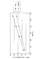
一方、作業ロールの最小ロール径は、同様に最小径上限Dmax1と最小径下限Dmin1間にあり、これらは下記の(5)式で表される。
最小径上限Dmax1=D4max×B/K(1/4) (5)式
ここで、D4max ; 従来板幅1,300mmの作業ロール最小径上限:φ380
B ; 板幅(mm)/1,300mm
K ; 高縦弾性材の従来材との比
(高縦弾性材の縦弾性係数/従来材の縦弾性係数(21,000kg/mm2))
本実施例の板幅毎の最小径上限Dmax1を図6に示す。ただし、作業ロール材質は、超硬合金の場合としてK=2.5とした。
最小径下限Dmin1= D4min × B/K(1/4) (6)式
ここで、D4min ; 従来板幅1,300mmの作業ロール最小径下限:φ180
本実施例の板幅毎の最小径下限Dmin1を図7に示す。ただし、作業ロール材質は、超硬合金の場合としてK=2.5とした。
On the other hand, the minimum roll diameter of the work roll is similarly between the minimum diameter upper limit Dmax1 and the minimum diameter lower limit Dmin1, and these are expressed by the following equation (5).
Minimum diameter upper limit Dmax1 = D4max × B / K (1/4) (5) where D4max; Conventional work roll minimum diameter upper limit of 1,300 mm: φ380
B; Plate width (mm) / 1,300mm
K: Ratio of high longitudinal elastic material to conventional material
(Longitudinal modulus of high longitudinal elastic material / longitudinal modulus of conventional material (21,000kg / mm 2 ))
FIG. 6 shows the minimum diameter upper limit Dmax1 for each plate width of this embodiment. However, the work roll material was K = 2.5 in the case of cemented carbide.
Minimum diameter lower limit Dmin1 = D4min x B / K (1/4) (6) where D4min; Minimum roll diameter lower limit for conventional rolls of 1,300 mm: φ180
FIG. 7 shows the minimum diameter lower limit Dmin1 for each plate width in this example. However, the work roll material was K = 2.5 in the case of cemented carbide.
このようにして、本実施例では、作業ロール2の圧延可能な板幅内,外に支持ロールを有しない6段ミルにおいて、高縦弾性材の超硬合金やセラミックス材質の作業ロール2を使用するので、作業ロールのたわみ剛性を確保してその高剛性分だけ、作業ロール径を小径にでき、硬質材圧延において高い生産性や高い製品品質の帯板1を得ることができる。
Thus, in this embodiment, the
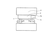
また、図8A,図8Bに示されるように、高縦弾性材の作業ロール2を水平方向の圧延方向入側に、入出側差張力(Tf−Tb)/2の大きさに応じ可変にオフセットさせても良い(図8A中のオフセット量α参照)。これにより、入出側差張力(Tf−Tb)/2は圧延荷重Qのオフセット水平方向分力Faにより減ぜられ、作業ロール2にかかる水平方向のトータルの力は減ぜられる。図8B中Fbはオフセット垂直方向分力を示す。
Further, as shown in FIGS. 8A and 8B, the
その結果、作業ロール2のたわみをより小さくできるメリットがある。
作業ロール2にかかる水平方向のトータルの力;Fwは、次の(7)式で示される。
Fw=(Tf−Tb)/2−Q×α/((Dw+DI)/2) (7)式
ここで、作業ロール径はDw、中間ロール径はDIとする。
As a result, there is an advantage that the deflection of the
The total horizontal force applied to the
Fw = (Tf−Tb) / 2−Q × α / ((Dw + DI) / 2) (7) where the work roll diameter is Dw and the intermediate roll diameter is DI.
また、図9A,図9Bに示されるように、中間ロール3を水平方向の圧延方向出側に、入出側差張力(Tf−Tb)/2の大きさに応じ可変にオフセットさせても良い(図9A中のオフセット量β参照)。これにより、入出側差張力(Tf−Tb)/2は圧延荷重Qのオフセット水平方向分力Faにより減ぜられ、高縦弾性材の作業ロール2にかかる水平方向のトータルの力は減ぜられる。図9B中Fbはオフセット垂直方向分力を示す。
Further, as shown in FIGS. 9A and 9B, the
その結果、作業ロール2のたわみをより小さくできるメリットがある。
作業ロール2にかかる水平方向のトータルの力;Fwは、次の(8)式で示される。
Fw=(Tf−Tb)/2−Q×β/((Dw+DI)/2) (8)式
ここで、作業ロール径はDw、中間ロール径はDIとする。
As a result, there is an advantage that the deflection of the
The total horizontal force applied to the
Fw = (Tf−Tb) / 2−Q × β / ((Dw + DI) / 2) (8) where the work roll diameter is Dw and the intermediate roll diameter is DI.
また、本実施例では、上下1対の作業ロール2は、軸方向にシフトする構造を示していないが、以下のように作業ロール2は、軸方向にシフト可能な構造としても良い。尚、作業ロールのシフト構造は、例えば特許文献2に示される構造がある。
Further, in this embodiment, the pair of upper and lower work rolls 2 does not show a structure that shifts in the axial direction, but the
図10に示すように、上下1対の作業ロール2は、帯板1の板幅中心に対して上下点対称方向のロール胴端部位置に先細り状のロール肩2aをそれぞれ有している。また、上下1対の作業ロール2のロールネック部には、図示されていない軸受が操作側と駆動側に取り付けられている。上下1対の作業ロール2は、この図示されていない駆動側軸受を介して、図示されていないシフトシリンダーにより、軸方向に移動可能となっている。
As shown in FIG. 10, the pair of upper and lower work rolls 2 have tapered
次に、先細り状のロール肩2aを持つ作業ロール2のシフトによるエッジドロップ低減方法について以下説明するが、先ず、作業ロール2は、上下点対称の方向に先細り状のロール肩2aが設けられ、このロール肩位置と板端までの距離をδw,δdとする。また、圧延機出側で操作側及び駆動側の板端部付近の1点又は複数の点の板厚みを測定する図示されていない板厚み計を設ける。
Next, an edge drop reduction method by shifting the
そして、上記操作側で測定された板端部付近の1点又は複数の点の板厚みが所定の板厚みより薄ければ、上作業ロール2をロール軸狭幅方向にシフトさせる。即ち、δwを大きくする方向に上作業ロール2をシフトさせるのである。また、逆に測定された板端部付近の板厚みが所定の板厚みより厚ければ、上作業ロール2をロール軸広幅方向にシフトさせる。即ち、δwを小さくする方向に上作業ロール2をシフトさせるのである。
If the plate thickness at one point or a plurality of points near the plate end measured on the operation side is smaller than the predetermined plate thickness, the
また、上記駆動側で測定された板端部付近の1点又は複数の点の板厚みが所定の板厚みと異なる場合、同様に所定の板厚みとなるよう下作業ロール2をシフトさせる。元々高縦弾性材の作業ロール2の適用により作業ロール径を小径にすることができるため、その分圧延荷重を下げることができ、結果歩留り低下の原因となるエッジドロップと呼ばれる板端部の急激な減厚を低減可能である。
Further, when the plate thickness at one point or a plurality of points in the vicinity of the plate end portion measured on the driving side is different from the predetermined plate thickness, the
この小径作業ロールと作業ロールシフトの併用により、先細り状のロール肩2aの最小化やシフト位置δw,dの最小化が可能となり、これらの値に敏感な割れ易い電磁鋼板等の脆性材料の圧延に特に好適である。尚、本図は、図1のミルを代表として記載しているが、図8の作業ロール可変オフセットミルや図9の中間ロール可変オフセットミルでも良い。
The combined use of this small-diameter work roll and work roll shift makes it possible to minimize the tapered
また、本実施例では、上下1対の中間ロール3は、帯板1の板幅中心に対して上下点対称のロール胴端部位置にロール径が減少するロール肩3aをそれぞれ有している例を示したが、上下1対の中間ロール3は、非特許文献1に示されるような帯板1の板幅中心に対して上下点対称のS字カーブロールクラウンを設け、軸方向にシフトさせる構造としても良い。この場合、ロール肩3aを持つ6段ミルよりも形状制御能力は劣るが、4段ミルよりも形状制御能力は優る。また、このミルに前述した図10に示される作業ロールシフトを適用しても良い。
Further, in this embodiment, the pair of upper and lower
図11は本発明の実施例2を示す4段ミルの正断面図、図12は図11のXII-XII線断面図、図13は実施例2の応用例を示す4段ミルの作業ロールシフトの説明図である。
11 is a front sectional view of a four-stage
本実施例の圧延機は、図11,図12に示すように、4段圧延機であり、実施例1である6段圧延機から上下1対の中間ロール3及び同軸受箱15a〜15d、ベンディングシリンダー16a〜16d一式を取り除いた構成となる。この場合、板形状制御能力は大きく低下するが構造がより簡易なものになる。
The rolling mill of this embodiment is a four-high rolling mill as shown in FIGS. 11 and 12, and a pair of upper and lower
また、本実施例では、上下1対の作業ロール2は、軸方向にシフトする構造を示していないが、図13のように、作業ロール2は、帯板1の板幅中心に対して上下点対称方向のロール胴端部位置に先細り状のロール肩2aをそれぞれ有し、軸方向にシフト可能な構造としても良い。これによると、より簡易な構造でエッジドロップ低減が可能となる。
In this embodiment, the pair of upper and lower work rolls 2 do not show a structure that shifts in the axial direction. However, as shown in FIG. It is good also as a structure which has the taper-shaped
また、前記応用例では、上下1対の作業ロール2は、帯板1の板幅中心に対して上下点対称方向のロール胴端部位置に先細り状のロール肩2aをそれぞれ有し、軸方向にシフト可能な構造の例を示したが、上下1対の作業ロール2は、非特許文献1に示されるような帯板1の板幅中心に対して上下点対称のS字カーブロールクラウンを設け、軸方向にシフトさせる構造としても良い。この場合、図13に示した4段ミルよりも形状制御能力は優る。
In the application example, the pair of upper and lower work rolls 2 each have a tapered
また、本発明の小径作業ロール圧延機をタンデム圧延機に適用する場合、図14に示されるように、NO.1スタンドに適用すると、高縦弾性材の小径作業ロールにより、強圧下が可能となる。また、最終スタンド、本図ではNO.4スタンドに適用すると、高縦弾性材の小径作業ロールにより、より薄い板が圧延可能となる。無論全スタンドについて本発明の小径作業ロール圧延機を適用しても良い。これにより、より薄くて硬い材料が圧延可能となる。尚、本図では、本発明の小径作業ロール圧延機として、6段ミルを代表として表示したが、4段ミルでも同様に適用できる。 Further, when the small diameter work roll rolling mill of the present invention is applied to a tandem rolling mill, as shown in FIG. When applied to a single stand, strong reduction is possible by a small diameter work roll made of high longitudinal elastic material. The final stand, NO. When applied to 4 stands, a thin plate can be rolled by a small diameter work roll of a high longitudinal elastic material. Of course, you may apply the small diameter work roll rolling mill of this invention about all the stands. Thereby, a thinner and harder material can be rolled. In this figure, as a small diameter work roll mill of the present invention, a 6-stage mill is shown as a representative, but a 4-stage mill can be similarly applied.
1 帯板
2 作業ロール
3 中間ロール
4 補強ロール
5a,5b パスライン調整装置
6a,6b 油圧シリンダー
7a,7b ハウジング
13a〜13d 作業ロール軸受箱
15a〜15d 中間ロール軸受箱
17a〜17d 補強ロール軸受箱
14a〜14d 作業ロールベンディングシリンダー
16a〜16d 中間ロールベンディングシリンダー
DESCRIPTION OF
Claims (3)
前記作業ロールが駆動されると共に、同作業ロールは、縦弾性係数21,000kg/mm2の従来材の縦弾性係数との比がK=1.2〜3.0である高い縦弾性係数の材質を使用した単一材から成り、その作業ロールの最小ロール径は、最小径上限Dmax1と最小径下限Dmin1間にあり、これらは下記式で表されることを特徴とする圧延機。
最小径上限Dmax1=D4max×B/K(1/4)
ここで、D4max ; 従来板幅1,300mmの作業ロール最小径上限:φ380
B ; 板幅(mm)/1,300mm
K ; 高縦弾性材の従来材との比
(高縦弾性材の縦弾性係数/従来材の縦弾性係数(21,000kg/mm2))
最小径下限Dmin1= D4min×B/K(1/4)
ここで、D4min ; 従来板幅1,300mmの作業ロール最小径下限:φ180 A pair of upper and lower work rolls for rolling the metal strip, a pair of upper and lower intermediate rolls for supporting the work roll, and a pair of upper and lower reinforcing rolls for supporting the pair of upper and lower intermediate rolls. In a 6-stage rolling mill that does not have a supporting roll inside and outside the rollable sheet width,
The work roll is driven, and the work roll is made of a material having a high longitudinal elastic modulus whose ratio with the longitudinal elastic modulus of the conventional material having a longitudinal elastic modulus of 21,000 kg / mm 2 is K = 1.2 to 3.0. A rolling mill characterized in that the minimum roll diameter of the work roll is between the minimum diameter upper limit Dmax1 and the minimum diameter lower limit Dmin1, and these are expressed by the following formula.
Minimum diameter upper limit Dmax1 = D4max × B / K (1/4)
Here, D4max; upper limit of minimum diameter of work roll with conventional plate width of 1,300mm: φ380
B; Board width (mm) / 1,300mm
K: Ratio of high longitudinal elastic material to conventional material
(Longitudinal modulus of high longitudinal elastic material / longitudinal modulus of conventional material (21,000kg / mm 2 ))
Minimum diameter lower limit Dmin1 = D4min × B / K (1/4)
Here, D4min; Minimum work roll minimum diameter of conventional plate width 1,300mm: φ180
前記作業ロールが駆動されると共に、同作業ロールは、縦弾性係数21,000kg/mm2の従来材の縦弾性係数との比がK=1.2〜3.0である高い縦弾性係数の材質を使用した単一材から成り、その作業ロールの最小ロール径は、最小径上限Dmax1と最小径下限Dmin1間にあり、これらは下記式で表されることを特徴とする圧延機。
最小径上限Dmax1=D4max×B/K(1/4)
ここで、D4max ; 従来板幅1,300mmの作業ロール最小径上限:φ380
B ; 板幅(mm)/1,300mm
K ; 高縦弾性材の従来材との比
(高縦弾性材の縦弾性係数/従来材の縦弾性係数(21,000kg/mm2))
最小径下限Dmin1= D4min×B/K(1/4)
ここで、D4min ; 従来板幅1,300mmの作業ロール最小径下限:φ180 It consists of a pair of upper and lower work rolls for rolling metal strips and a pair of upper and lower reinforcing rolls for supporting the work rolls, and is a four-stage type having no support rolls inside and outside the roll width of the work rolls that can be rolled. In the rolling mill,
The work roll is driven, and the work roll is made of a material having a high longitudinal elastic modulus whose ratio with the longitudinal elastic modulus of the conventional material having a longitudinal elastic modulus of 21,000 kg / mm 2 is K = 1.2 to 3.0. A rolling mill characterized in that the minimum roll diameter of the work roll is between the minimum diameter upper limit Dmax1 and the minimum diameter lower limit Dmin1, and these are expressed by the following formula.
Minimum diameter upper limit Dmax1 = D4max × B / K (1/4)
Here, D4max; upper limit of minimum diameter of work roll with conventional plate width of 1,300mm: φ380
B; Board width (mm) / 1,300mm
K: Ratio of high longitudinal elastic material to conventional material
(Longitudinal modulus of high longitudinal elastic material / longitudinal modulus of conventional material (21,000kg / mm 2 ))
Minimum diameter lower limit Dmin1 = D4min × B / K (1/4)
Here, D4min; Minimum work roll minimum diameter of conventional plate width 1,300mm: φ180
Priority Applications (3)
| Application Number | Priority Date | Filing Date | Title |
|---|---|---|---|
| JP2009170815A JP5568261B2 (en) | 2009-07-22 | 2009-07-22 | Rolling mill and tandem rolling mill equipped with the rolling mill |
| EP10007529A EP2277637B1 (en) | 2009-07-22 | 2010-07-20 | Rolling mill and tandem rolling mill having the same |
| CN 201010234089 CN101961729B (en) | 2009-07-22 | 2010-07-20 | Rolling mill and tandem rolling mill having the same |
Applications Claiming Priority (1)
| Application Number | Priority Date | Filing Date | Title |
|---|---|---|---|
| JP2009170815A JP5568261B2 (en) | 2009-07-22 | 2009-07-22 | Rolling mill and tandem rolling mill equipped with the rolling mill |
Publications (2)
| Publication Number | Publication Date |
|---|---|
| JP2011025253A JP2011025253A (en) | 2011-02-10 |
| JP5568261B2 true JP5568261B2 (en) | 2014-08-06 |
Family
ID=43034297
Family Applications (1)
| Application Number | Title | Priority Date | Filing Date |
|---|---|---|---|
| JP2009170815A Active JP5568261B2 (en) | 2009-07-22 | 2009-07-22 | Rolling mill and tandem rolling mill equipped with the rolling mill |
Country Status (3)
| Country | Link |
|---|---|
| EP (1) | EP2277637B1 (en) |
| JP (1) | JP5568261B2 (en) |
| CN (1) | CN101961729B (en) |
Families Citing this family (4)
| Publication number | Priority date | Publication date | Assignee | Title |
|---|---|---|---|---|
| JP5683082B2 (en) * | 2009-07-29 | 2015-03-11 | 三菱日立製鉄機械株式会社 | Rolling mill with work roll shift function |
| CN104209325A (en) * | 2014-09-10 | 2014-12-17 | 中冶南方工程技术有限公司 | Large roll, small roll and bent roll system suitable for double-stand flattening and double cold reduction unit |
| JP6470134B2 (en) * | 2015-07-08 | 2019-02-13 | Primetals Technologies Japan株式会社 | Rolling mill and rolling method |
| CN111318569B (en) * | 2020-03-24 | 2021-08-24 | 河北东海特钢集团有限公司 | Steel plate cold rolling equipment |
Family Cites Families (9)
| Publication number | Priority date | Publication date | Assignee | Title |
|---|---|---|---|---|
| JPS60238021A (en) | 1984-05-10 | 1985-11-26 | Ishikawajima Harima Heavy Ind Co Ltd | Rolling mill |
| JP2972401B2 (en) | 1991-08-26 | 1999-11-08 | 株式会社日立製作所 | Rolling mill and rolling method |
| JP3209705B2 (en) * | 1997-03-25 | 2001-09-17 | 川崎製鉄株式会社 | Composite roll for cold rolling |
| TW401326B (en) * | 1998-03-23 | 2000-08-11 | Kawasaki Steel Co | Method of manufacturing metal foil |
| JP2002066608A (en) * | 2000-08-30 | 2002-03-05 | Hitachi Ltd | Cold rolling mill and rolling method |
| DE10046426A1 (en) * | 2000-09-20 | 2002-03-28 | Sms Demag Ag | Four high rolling stand, used in rolling mill for rolling hot and cold strips, comprises two working rollers and supporting rollers driven by drive spindles with one supporting roller detachably connected to motor |
| DE10208389B4 (en) * | 2001-07-11 | 2004-11-04 | Hitachi, Ltd. | Roll stand, rolling mill and rolling process |
| JP2003275803A (en) * | 2002-03-20 | 2003-09-30 | Jfe Steel Kk | Method for cold-rolling metallic sheet having excellent gloss |
| JP5138398B2 (en) * | 2008-01-25 | 2013-02-06 | 三菱日立製鉄機械株式会社 | Rolling mill and tandem rolling mill equipped with the rolling mill |
-
2009
- 2009-07-22 JP JP2009170815A patent/JP5568261B2/en active Active
-
2010
- 2010-07-20 CN CN 201010234089 patent/CN101961729B/en active Active
- 2010-07-20 EP EP10007529A patent/EP2277637B1/en active Active
Also Published As
| Publication number | Publication date |
|---|---|
| CN101961729B (en) | 2012-12-26 |
| EP2277637B1 (en) | 2013-03-27 |
| EP2277637A1 (en) | 2011-01-26 |
| JP2011025253A (en) | 2011-02-10 |
| CN101961729A (en) | 2011-02-02 |
Similar Documents
| Publication | Publication Date | Title |
|---|---|---|
| JP5491090B2 (en) | Rolling mill and tandem rolling mill equipped with the rolling mill | |
| JP5138397B2 (en) | Rolling mill and tandem rolling mill equipped with the rolling mill | |
| JP5138398B2 (en) | Rolling mill and tandem rolling mill equipped with the rolling mill | |
| JP5568261B2 (en) | Rolling mill and tandem rolling mill equipped with the rolling mill | |
| EP2772321B1 (en) | Rolling mill having work roll shifting function | |
| EP2656934B1 (en) | Multi-high rolling mill equipped with work roll shift function | |
| JP5711232B2 (en) | How to set the work roll diameter | |
| JP5905322B2 (en) | Rolling mill with work roll shift function | |
| US8794045B2 (en) | Cluster-type multistage rolling mill | |
| WO1988000863A1 (en) | Multistage rolling mill | |
| WO2019221297A1 (en) | Rolling mill and setting method for rolling mill | |
| WO2002002251A1 (en) | Rolling mill and rolling method | |
| JPH1058011A (en) | Mechanism for offsetting intermediate roll of rolling mill | |
| JPH0313219A (en) | Rolling mill | |
| JPH0342104A (en) | Work roll for rolling |
Legal Events
| Date | Code | Title | Description |
|---|---|---|---|
| A621 | Written request for application examination |
Free format text: JAPANESE INTERMEDIATE CODE: A621 Effective date: 20120522 |
|
| A977 | Report on retrieval |
Free format text: JAPANESE INTERMEDIATE CODE: A971007 Effective date: 20131028 |
|
| A131 | Notification of reasons for refusal |
Free format text: JAPANESE INTERMEDIATE CODE: A131 Effective date: 20131105 |
|
| A521 | Request for written amendment filed |
Free format text: JAPANESE INTERMEDIATE CODE: A523 Effective date: 20131227 |
|
| A02 | Decision of refusal |
Free format text: JAPANESE INTERMEDIATE CODE: A02 Effective date: 20140225 |
|
| A521 | Request for written amendment filed |
Free format text: JAPANESE INTERMEDIATE CODE: A523 Effective date: 20140526 |
|
| A911 | Transfer to examiner for re-examination before appeal (zenchi) |
Free format text: JAPANESE INTERMEDIATE CODE: A911 Effective date: 20140602 |
|
| TRDD | Decision of grant or rejection written | ||
| A01 | Written decision to grant a patent or to grant a registration (utility model) |
Free format text: JAPANESE INTERMEDIATE CODE: A01 Effective date: 20140617 |
|
| A61 | First payment of annual fees (during grant procedure) |
Free format text: JAPANESE INTERMEDIATE CODE: A61 Effective date: 20140623 |
|
| R150 | Certificate of patent or registration of utility model |
Ref document number: 5568261 Country of ref document: JP Free format text: JAPANESE INTERMEDIATE CODE: R150 |
|
| R250 | Receipt of annual fees |
Free format text: JAPANESE INTERMEDIATE CODE: R250 |
|
| R250 | Receipt of annual fees |
Free format text: JAPANESE INTERMEDIATE CODE: R250 |
|
| R250 | Receipt of annual fees |
Free format text: JAPANESE INTERMEDIATE CODE: R250 |
|
| S111 | Request for change of ownership or part of ownership |
Free format text: JAPANESE INTERMEDIATE CODE: R313111 |
|
| R250 | Receipt of annual fees |
Free format text: JAPANESE INTERMEDIATE CODE: R250 |
|
| R350 | Written notification of registration of transfer |
Free format text: JAPANESE INTERMEDIATE CODE: R350 |
|
| R250 | Receipt of annual fees |
Free format text: JAPANESE INTERMEDIATE CODE: R250 |
|
| R250 | Receipt of annual fees |
Free format text: JAPANESE INTERMEDIATE CODE: R250 |
|
| R250 | Receipt of annual fees |
Free format text: JAPANESE INTERMEDIATE CODE: R250 |