JP5565912B2 - Color prediction method, color conversion lookup table generation method, image processing method, and image processing apparatus - Google Patents
Color prediction method, color conversion lookup table generation method, image processing method, and image processing apparatus Download PDFInfo
- Publication number
- JP5565912B2 JP5565912B2 JP2011277351A JP2011277351A JP5565912B2 JP 5565912 B2 JP5565912 B2 JP 5565912B2 JP 2011277351 A JP2011277351 A JP 2011277351A JP 2011277351 A JP2011277351 A JP 2011277351A JP 5565912 B2 JP5565912 B2 JP 5565912B2
- Authority
- JP
- Japan
- Prior art keywords
- color
- colorimetric
- patch group
- value
- color material
- Prior art date
- Legal status (The legal status is an assumption and is not a legal conclusion. Google has not performed a legal analysis and makes no representation as to the accuracy of the status listed.)
- Expired - Fee Related
Links
Images


Classifications
-
- H—ELECTRICITY
- H04—ELECTRIC COMMUNICATION TECHNIQUE
- H04N—PICTORIAL COMMUNICATION, e.g. TELEVISION
- H04N1/00—Scanning, transmission or reproduction of documents or the like, e.g. facsimile transmission; Details thereof
- H04N1/46—Colour picture communication systems
- H04N1/56—Processing of colour picture signals
- H04N1/60—Colour correction or control
- H04N1/603—Colour correction or control controlled by characteristics of the picture signal generator or the picture reproducer
-
- H—ELECTRICITY
- H04—ELECTRIC COMMUNICATION TECHNIQUE
- H04N—PICTORIAL COMMUNICATION, e.g. TELEVISION
- H04N1/00—Scanning, transmission or reproduction of documents or the like, e.g. facsimile transmission; Details thereof
- H04N1/46—Colour picture communication systems
- H04N1/52—Circuits or arrangements for halftone screening
-
- H—ELECTRICITY
- H04—ELECTRIC COMMUNICATION TECHNIQUE
- H04N—PICTORIAL COMMUNICATION, e.g. TELEVISION
- H04N1/00—Scanning, transmission or reproduction of documents or the like, e.g. facsimile transmission; Details thereof
- H04N1/46—Colour picture communication systems
- H04N1/56—Processing of colour picture signals
- H04N1/60—Colour correction or control
- H04N1/6016—Conversion to subtractive colour signals
- H04N1/6022—Generating a fourth subtractive colour signal, e.g. under colour removal, black masking
- H04N1/6025—Generating a fourth subtractive colour signal, e.g. under colour removal, black masking using look-up tables
-
- H—ELECTRICITY
- H04—ELECTRIC COMMUNICATION TECHNIQUE
- H04N—PICTORIAL COMMUNICATION, e.g. TELEVISION
- H04N1/00—Scanning, transmission or reproduction of documents or the like, e.g. facsimile transmission; Details thereof
- H04N1/46—Colour picture communication systems
- H04N1/56—Processing of colour picture signals
- H04N1/60—Colour correction or control
- H04N1/603—Colour correction or control controlled by characteristics of the picture signal generator or the picture reproducer
- H04N1/6033—Colour correction or control controlled by characteristics of the picture signal generator or the picture reproducer using test pattern analysis
- H04N1/605—Colour correction or control controlled by characteristics of the picture signal generator or the picture reproducer using test pattern analysis for controlling ink amount, strike-through, bleeding soakage or the like
Description
本発明は色予測方法、色変換ルックアップテーブル生成方法、画像処理方法及び画像処理装置に係り、特にカラー画像形成における画像形成データの色修正技術に関する。 The present invention relates to a color prediction method, a color conversion lookup table generation method, an image processing method, and an image processing apparatus, and more particularly to a color correction technique for image formation data in color image formation.
一般に、インクジェット記録装置や電子写真方式の画像形成装置では、Y(イエロー)、M(マゼンタ)、C(シアン)、K(黒)などの複数色の色材が用いられる。かかる色材により実現される色空間は、元の画像データとは異なる色空間を有しているので、元の画像データが示す色や階調を忠実に再現するために、色変換(色修正)処理が行われる。 In general, an inkjet recording apparatus or an electrophotographic image forming apparatus uses a plurality of color materials such as Y (yellow), M (magenta), C (cyan), and K (black). Since the color space realized by such a color material has a color space different from the original image data, color conversion (color correction) is performed in order to faithfully reproduce the color and gradation indicated by the original image data. ) Processing is performed.
一方、画像形成の出力媒体の特性によって、受容可能な色材の量が制限されることがある。例えば、インクジェット記録装置を用いて紙媒体にカラー画像を形成する際に、該紙媒体が吸収しうる量を超えるインクが付与されると、紙媒体の変形が生じてしまう。かかる紙媒体の変形により、該紙媒体の搬送異常の発生や該紙媒体に形成される画像の品質低下が懸念される。 On the other hand, the amount of acceptable color material may be limited by the characteristics of the output medium for image formation. For example, when a color image is formed on a paper medium using an ink jet recording apparatus, if the ink exceeding the amount that the paper medium can absorb is applied, the paper medium is deformed. Due to such deformation of the paper medium, there is a concern about the occurrence of abnormal conveyance of the paper medium and a decrease in the quality of the image formed on the paper medium.
また、紙が変形しない場合でも、色材量が過剰になることで、色材が十分に媒体上に定着せず膜質特性が低下して、擦りに弱くなることや、画像形成後に媒体を重ねた際に、別の媒体に裏移りするなどの問題が発生することがある。 Even when the paper is not deformed, the amount of the coloring material becomes excessive, so that the coloring material is not sufficiently fixed on the medium, and the film quality characteristic is deteriorated and becomes weak against rubbing. In such a case, there may be a problem such as turning over to another medium.
特許文献1は、パッチを測色し、測色されたデータに基づいて色分解テーブル(信号値から色材使用量を計算する色分解処理に用いられるテーブル)を生成する際に、記録媒体に対するインクの吸収特性等により決められる最大色材総使用量よりも大きい色材使用量のパッチがあるときに、すべてのパッチが最大色材総使用量の範囲内に入るように信号値の圧縮を行い、最大色材総使用量の範囲内の色分解テーブルを生成する方法を開示している。 Japanese Patent Application Laid-Open No. 2004-228867 measures the color of a patch and generates a color separation table (a table used for color separation processing for calculating a color material usage amount from a signal value) based on the colorimetric data. When there is a patch with a colorant usage greater than the maximum colorant usage determined by the ink absorption characteristics, etc., the signal value is compressed so that all patches fall within the range of the maximum colorant usage. And a method of generating a color separation table within the range of the maximum total color material usage is disclosed.
しかしながら、特許文献1に開示された色分解テーブルを生成する方法は、以下の課題が存在している。すなわち、予め最大色材総使用量を正確に求めることは難しく、曖昧性が残ることが多い。 However, the method for generating the color separation table disclosed in Patent Document 1 has the following problems. That is, it is difficult to accurately obtain the maximum color material total usage amount in advance, and ambiguity often remains.
また、最大色材総使用量が変更されると、変更後の最大色材総使用量に基づきチャート(パッチ)の生成、該チャートの出力、出力されたチャートの測色を経て、測色結果から色分解テーブルの再生成が必要となることがありうる。 Further, when the maximum total color material usage is changed, a color measurement result is generated through generation of a chart (patch) based on the changed maximum color material total usage, output of the chart, and color measurement of the output chart. Therefore, it may be necessary to regenerate the color separation table.
特に、最大色材総使用量が増えると、すでに生成されている色分解テーブルに存在していないデータが必要になり、色分解テーブルの再生成が必須となる。例えば、記録媒体の種類や厚みの変更(記録媒体の種類を変更せずに厚みを変更する場合を含む)、搬送機構の改善によるハードウエアの改良等によって最大色材総使用量が変更されると、新たな最大色材総使用量に基づき色分解テーブルを再生成しなければならず、極めて非効率的である。 In particular, when the maximum total color material usage amount increases, data that does not exist in the already generated color separation table is required, and it is necessary to regenerate the color separation table. For example, the maximum total color material usage is changed by changing the type and thickness of the recording medium (including changing the thickness without changing the type of recording medium), improving the hardware by improving the transport mechanism, etc. In addition, the color separation table must be regenerated based on the new maximum total color material usage amount, which is extremely inefficient.
本発明はこのような事情に鑑みてなされたもので、色材の過剰な付与が生じないように形成されたパッチの測色値に基づき、精度の高い色予測を可能とする、色予測方法、色変換ルックアップテーブル生成方法、画像処理方法及び画像処理装置を提供することを目的とする。 The present invention has been made in view of such circumstances, and a color prediction method that enables highly accurate color prediction based on colorimetric values of patches formed so as not to cause excessive application of color materials. Another object of the present invention is to provide a color conversion lookup table generation method, an image processing method, and an image processing apparatus.
上記目的を達成するために、本発明に係る色予測方法は、複数色に対応する多次元の色空間において、仮の色材使用制限値を設定する色材使用制限値設定工程と、予め定められた色材の組み合わせにおける色材使用値の合計値が、設定された使用制限値以下の領域について、定められた色材使用値の組み合わせに基づく複数のパッチを含むパッチ群を作成するパッチ群作成工程と、作成されたパッチ群を媒体へ出力するパッチ群出力工程と、パッチ群を測色する測色工程と、測色された各パッチの測色値に基づき、色材使用制限値を超える領域の仮想的なパッチの測色値を補外演算により推定する測色値推定工程と、測色工程及び測色値推定工程により得られた測色値に基づいて、色空間における色材使用値の組み合わせに対する色を補間演算により予測する色予測工程と、を含み、パッチ群作成工程は、色材使用制限値以下であり、色材使用制限値の測色値又は色材使用制限値の近傍の測色値を有し、測色値推定工程における補外演算に用いられる学習データとして使用される混色の補外演算用パッチ群を作成する補外演算用パッチ群作成工程を含んでいる。 In order to achieve the above object, a color prediction method according to the present invention includes a color material use limit value setting step for setting a temporary color material use limit value in a multidimensional color space corresponding to a plurality of colors, and a predetermined step. the total value of the color material usage values in the combination of the coloring material that has been found for the set have been used limit the following areas, to create a patch group including a plurality of patches based on a combination of the constant order was colorant used values a patch group creation step, and a patch group output step of outputting the created made patch group to the medium, a color measurement step for colorimetry patch group, based on the colorimetric values of each patch colorimetric color and colorimetric value estimation step of estimating the extrapolation calculates colorimetric value of the virtual patch region exceeding wood use limit value, based on the color measurement values obtained by the color measurement process及beauty colorimetric values estimating step interpolation Starring color for a combination of color material usage values in the color space Color prediction process and, only containing patch group creation step of predicting by is less color material use limit, have a colorimetric value of the vicinity of the colorimetric values or color material use limit of the colorant used limit and has Nde including extrapolation calculation patch group creation step of creating extrapolation calculation patch group of color mixing to be used as learning data used for extrapolation operation in the colorimetric value estimation step.
本発明によれば、色材使用量が制限され、正確な色材使用制限値がわからずに曖昧さが残されていても、擬似的に仮の色材使用制限値が設定され、色材使用制限値を超える領域の仮想的なパッチの測色値が補外演算により推定され、推定された測色値を用いて補間演算により色材使用制限値を超える領域の測色値が予測されるので、色材使用制限値を超えた任意の入力に対する色の予測が可能となる。 According to the present invention, even if the amount of color material used is limited and the ambiguity remains without knowing the exact color material use limit value, a pseudo color material use limit value is set in a pseudo manner, and the color material The colorimetric values of the virtual patches in the area exceeding the usage limit value are estimated by extrapolation, and the colorimetric values in the area exceeding the color material usage limit value are predicted by interpolation using the estimated colorimetric value. Therefore, it is possible to predict a color for an arbitrary input exceeding the color material usage limit value.
また、仮の色材使用制限値周辺領域の測色値は予測精度が特に高いため、色材使用制限値が変更されたとしても、パッチ群作成、パッチ群出力、測色といった一連の処理を行う必要がない。さらに、補外演算用パッチ群の測色結果を用いて、好ましい補外演算が実行される。さらにまた、色材使用制限値の近傍に色材使用制限値の変動範囲が含まれることで、色材使用制限値の変動範囲における色予測の精度が向上する。 In addition, since the colorimetric values in the surrounding area of the temporary color material use limit value have a particularly high prediction accuracy, even if the color material use limit value is changed, a series of processes such as patch group creation, patch group output, and color measurement are performed. There is no need to do it. Furthermore, a preferable extrapolation calculation is executed using the colorimetric results of the extrapolation calculation patch group. Furthermore, since the variation range of the color material use restriction value is included in the vicinity of the color material use restriction value, the accuracy of color prediction in the variation range of the color material use restriction value is improved.
以下、添付図面に従って本発明を実施するための形態について詳説する。 Hereinafter, embodiments for carrying out the present invention will be described in detail with reference to the accompanying drawings.
〔色予測方法の概略〕
図1は、本発明の実施形態に係る色予測方法(色変換ルックアップテーブル(LUT)作成方法)の概略構成を示すフローチャートである。以下に説明する色予測方法は、画像形成装置の個別の出力色特性に起因する出力色の違いを補正するために、入力データに対する出力色の予測に使用される技術である。
[Outline of color prediction method]
FIG. 1 is a flowchart showing a schematic configuration of a color prediction method (color conversion lookup table (LUT) creation method) according to an embodiment of the present invention. The color prediction method described below is a technique used to predict an output color for input data in order to correct a difference in output color caused by individual output color characteristics of the image forming apparatus.
同図に示す色予測方法は、印刷機(画像形成装置)の出力色特性を解析するためのパッチ群(チャート画像)を作成するパッチ群作成工程と(ステップS12)、ステップS12において作成されたパッチ群を媒体へ出力するパッチ群出力工程と(ステップS14)、媒体上へ出力されたパッチ群を測色する測色工程と(ステップS16)、ステップS16の測色工程の測色結果に基づき、色空間における測色値を予測するための出力色予測器を生成する出力色予測器生成工程と(ステップS18)と、を含んで構成される。 The color prediction method shown in the figure is created in a patch group creating step (step S12) for creating a patch group (chart image) for analyzing output color characteristics of a printing press (image forming apparatus), and in step S12. Based on the patch group output process for outputting the patch group to the medium (step S14), the color measurement process for measuring the color of the patch group output on the medium (step S16), and the color measurement result of the color measurement process of step S16. An output color predictor generating step for generating an output color predictor for predicting a colorimetric value in the color space (step S18).
また、ステップS18において生成された出力色予測器を用いて任意の入力信号値に対する測色値を予測して、デバイス依存色をデバイス非依存色へ変換するための色変換LUTを作成する工程や、あるいは、その逆のデバイス非依存色をデバイス依存色へ変換するための色変換LUTを作成する工程である色変換LUT生成工程と(ステップS20)、を含んでいてもよい。 Also, a process of creating a color conversion LUT for predicting a colorimetric value for an arbitrary input signal value using the output color predictor generated in step S18 and converting a device-dependent color into a device-independent color, Alternatively, it may include a color conversion LUT generation step (step S20), which is a step of creating a color conversion LUT for converting a device-independent color to a device-dependent color.
以下に、図1に図示したステップS12からステップS20の各工程を工程順に詳説する。 Below, each process of step S12 to step S20 illustrated in FIG.
〔パッチ群(チャート画像)作成工程〕
まず、画像形成における出力色特性を解析するためのパッチ群(チャート画像)が作成される。図2は、図1のパッチ群作成工程(ステップS12)の詳細を示すフローチャートである。
[Patch group (chart image) creation process]
First, a patch group (chart image) for analyzing output color characteristics in image formation is created. FIG. 2 is a flowchart showing details of the patch group creation step (step S12) of FIG.
図2に示すパッチ群作成工程は、色材の仮の使用制限値を設定する色材使用制限値設定工程と(ステップS32)、ステップS32で設定された色材の仮の使用制限値を考慮せずに全領域(4色であれば0%から400%)について第1パッチ群を作成する第1パッチ群作成工程と(ステップS34)、ステップS34で作成された第1パッチ群から色材の仮の使用制限値を超えた領域のパッチ群を除いた第2パッチ群を作成する第2パッチ群作成工程と(ステップS36)、を含んで構成される。 The patch group creation process shown in FIG. 2 considers the color material use limit value setting step for setting the temporary use limit value of the color material (step S32) and the provisional use limit value of the color material set in step S32. The first patch group creating step for creating the first patch group for all regions (0% to 400% for four colors) without color (Step S34), and the color material from the first patch group created in Step S34 And a second patch group creating step of creating a second patch group excluding the patch group in the region exceeding the temporary use limit value (step S36).
例えば、C(シアン)、M(マゼンタ)、Y(イエロー)、K(黒)が用いられるカラー画像形成では、1色あたりの色材の最大使用量を100%とすると、4色の合計最大使用量は400%となる。 For example, in color image formation in which C (cyan), M (magenta), Y (yellow), and K (black) are used, assuming that the maximum amount of color material used per color is 100%, the total maximum of four colors The amount used is 400%.
インクジェット方式の画像形成において、4色のインクが最大使用量の近傍で使用される場合は、重畳的に付与されるインクを用紙が吸収することができず、パッチの正確な色再現がされないことや、過剰に付与されたインクによる膜特性の低下が生じること、過剰に付与されたインクにより用紙にたわみが生じてしまい、用紙搬送に問題が生じることがありうる。 When four colors of ink are used in the vicinity of the maximum amount used in inkjet image formation, the paper cannot absorb the superimposed ink and the color reproduction of the patch is not accurate. In addition, the film characteristics may be deteriorated due to the excessively applied ink, and the paper may be bent due to the excessively applied ink, which may cause a problem in paper conveyance.
一方、予めインクの最大使用可能量が把握できれば、該インク最大使用可能量の制限の下で、パッチ群を作成することが可能であるものの、装置と用紙(媒体)との組み合わせごとのそれぞれについて、インクの最大使用可能量を正確に求めることは困難であり、曖昧さが残ることが多い。 On the other hand, if the maximum usable amount of ink can be grasped in advance, a patch group can be created under the restriction of the maximum usable amount of ink, but for each combination of apparatus and paper (medium). It is difficult to accurately determine the maximum usable amount of ink, and ambiguity often remains.
また、用紙の変更(用紙厚みの変更)や装置のハードウエアの改良、インクの種類等によって、インクの最大使用可能量が変更されることがありうる。 Further, the maximum usable amount of ink may be changed by changing the paper (changing the paper thickness), improving the hardware of the apparatus, and the type of ink.
そこで、本例に示す色予測方法では、まず、曖昧さが残されたインクの最大使用可能量である仮の色材使用制限値が設定される(ステップS32)。例えば、n次元色空間において、n×100%を最大値(%)として、最大値に対する百分率(例えば、4次元色空間において250%)として設定される。 Therefore, in the color prediction method shown in the present example, first, a temporary color material use limit value that is the maximum usable amount of ink with ambiguity remaining is set (step S32). For example, in the n-dimensional color space, n × 100% is set as the maximum value (%), and the percentage is set as a percentage (for example, 250% in the 4-dimensional color space).
次に、各色インクの使用量が最小(0%)から最大(100%)の範囲において、第1パッチ群が作成される(ステップS34)。ステップS34において作成された第1パッチ群は実際に出力されない仮想的なものである。 Next, the first patch group is created in the range where the usage amount of each color ink is the minimum (0%) to the maximum (100%) (step S34). The first patch group created in step S34 is a virtual one that is not actually output.
さらに、ステップS34において第1パッチ群が作成されると、第1パッチ群からステップS32において設定された色材使用制限値を超える領域のパッチ群が除かれた第2パッチ群が作成され(ステップS36)、パッチ群作成工程は終了される(ステップS38)。 Further, when the first patch group is created in step S34, a second patch group is created by removing the patch group in the area exceeding the color material use limit value set in step S32 from the first patch group (step S34). S36), the patch group creation step is ended (step S38).
すなわち、ステップS32において設定された色材使用制限値を考慮せずに、ステップS34において多次元色空間の全領域を対象とする第1パッチ群が作成され、次いで、ステップS36において、該第1パッチ群に基づいて色材使用制限値以下の領域を対象とする第2パッチ群が作成される。 That is, the first patch group for the entire region of the multidimensional color space is created in step S34 without considering the color material usage limit value set in step S32. Then, in step S36, the first patch group is created. Based on the patch group, a second patch group for an area that is equal to or less than the color material use limit value is created.
第2のパッチ群の図示は省略するが、単色多階調部と、色予測基底格子点部と、補外演算用学習部と、を含んで構成される。以下に、図3を用いて、第2パッチ群を構成する各部について説明する。 Although illustration of the second patch group is omitted, the second patch group includes a single-color multi-gradation part, a color prediction basis grid point part, and an extrapolation calculation learning part. Hereinafter, the respective parts constituting the second patch group will be described with reference to FIG.
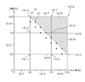
図3は、シアン(C)及びマゼンタ(M)により構成される2次元色空間を模式的に図示した説明図である。図3では、説明(図示)を簡単にするために2次元色空間としたが、実際には、n色(nは正の整数)の色材が使用される画像形成ではn次色空間となる。 FIG. 3 is an explanatory diagram schematically showing a two-dimensional color space composed of cyan (C) and magenta (M). In FIG. 3, a two-dimensional color space is used to simplify the description (illustrated). However, in actuality, an n-order color space is used in image formation in which n color materials (n is a positive integer) are used. Become.
なお、図3に符号10を付した破線は、仮の色材使用制限値(最大値200%に対して130%)を表しており、図3のドットハッチを付した領域は、色材使用制限値を超える領域を表している。また、符号12、14を付した黒塗り三角形は、補外演算用学習部(詳細後述)のパッチに対応する測色値(色値)を表している。
3 represents the temporary color material use limit value (130% with respect to the maximum value of 200%), and the area with the dot hatching in FIG. It represents an area that exceeds the limit value. Black triangles with
(単色多階調部)
まず、単色階調部について説明する。単色階調部は、使用される色ごとに理論網点面積率(「理論網点面積率」の詳細は後述)を変えながら作成された複数の単色のパッチから構成される。例えば、CMYKを用いた4色の画像形成では、CMYKのそれぞれの理論網点面積率が0%、5%、10%、…、100%といったパッチが含まれる。
(Single color multi-gradation part)
First, the monochromatic gradation part will be described. The single color gradation portion is composed of a plurality of single color patches created while changing the theoretical halftone dot area ratio (details of “theoretical halftone dot area ratio” will be described later) for each color used. For example, in the four-color image formation using CMYK, patches in which the theoretical halftone dot area ratio of CMYK is 0%, 5%, 10%,..., 100% are included.
これらのパッチの測色値は、単色ドットゲイン補正処理の入力データ(例えば、図3に示す色空間における各色軸の目盛り)として使用される。単色ドットゲイン補正処理は、理論網点面積率の変化に対する測色値(あるいは、実効網点面積率)の変化の非線形性を補正する処理である(詳細後述)。 The colorimetric values of these patches are used as input data for monochrome dot gain correction processing (for example, the scale of each color axis in the color space shown in FIG. 3). The monochromatic dot gain correction process is a process for correcting the nonlinearity of the change in the colorimetric value (or effective halftone dot area ratio) with respect to the change in the theoretical halftone dot area ratio (details will be described later).
なお、単色階調部を構成する各パッチの理論網点面積率をより細かく刻んで作成することにより、単色ドットゲイン補正処理の補正精度を向上させることができる。また、パッチの理論網点面積率の刻みは必ずしも等間隔である必要はない。例えば、理論網点面積率の増加に対する測色値の変動の非線形性が大きい階調が予めわかっている場合は(例えば、最大値近傍、最小値近傍等)、その階調付近のみパッチの理論網点面積率の刻みを細かくすることで、総パッチ数を増加させずに補正精度を向上させることができる。 It should be noted that the correction accuracy of the monochrome dot gain correction process can be improved by making the theoretical halftone dot area ratio of each patch constituting the monochrome gradation part finer. Further, the increments of the theoretical halftone dot area ratio of the patches do not necessarily need to be equal. For example, when a gradation having a large non-linearity in the variation of the colorimetric value with respect to an increase in the theoretical halftone dot area ratio is known in advance (for example, near the maximum value, near the minimum value, etc.), the patch theory is used only near that gradation. By making the halftone dot area rate finer, it is possible to improve the correction accuracy without increasing the total number of patches.
図3に示すように、シアン(c)、マゼンタ(M)のそれぞれについて、理論網点面積率が0%から70%の間は10%刻みでパッチが形成され、理論網点面積率が70%から100%の間(最大値近傍)は5%刻みでパッチが形成される。 As shown in FIG. 3, for each of cyan (c) and magenta (M), patches are formed in increments of 10% when the theoretical halftone dot area ratio is between 0% and 70%, and the theoretical halftone dot area ratio is 70%. Between 100% and 100% (near the maximum value), patches are formed in 5% increments.
(色予測基底格子点部)
次に、色予測基底格子点部について説明する。「色予測基底格子点」とは、n次元色空間をm個(mは1以上の整数)の矩形格子状に分割したときの各格子の頂点である。なお、m=1の場合は分割を行わないことを意味する。
(Color prediction basis grid point)
Next, the color prediction basis grid point portion will be described. “Color prediction base grid points” are the vertices of each grid when the n-dimensional color space is divided into m (m is an integer of 1 or more) rectangular grids. If m = 1, it means that no division is performed.
「色予測基底格子点部」は、各頂点における各色の理論網点面積率が指定されたパッチ群により構成される。なお、先に説明したように、色予測基底格子点部は仮の色材使用制限値を超える領域の網点面積率に対応するパッチは含まれていない。 The “color prediction basis grid point portion” is configured by a patch group in which the theoretical halftone dot area ratio of each color at each vertex is designated. As described above, the color prediction base grid point portion does not include a patch corresponding to the halftone dot area ratio in a region exceeding the provisional color material use limit value.
n次元色空間の各軸がm分割される場合は、「色予測基底格子点部」を構成するパッチの候補としてnm+1個のパッチが考えられる。なお、nm+1個のパッチ候補のうち、n×(m+1)個のパッチは単色パッチ(各色軸上の格子点に対応するパッチ)であり、単色パッチは先に説明した単色多階調部に含めることができる。 When each axis of the n-dimensional color space is divided into m , n m + 1 patches can be considered as candidate patches constituting the “color prediction base lattice point”. Of the n m + 1 patch candidates, n × (m + 1) patches are single color patches (corresponding to grid points on each color axis), and the single color patches are included in the single color multi-gradation portion described above. Can be included.
なお、m+1個のパッチには、理論網点面積率が0%以外のm個のパッチに、全ての色材の理論網点面積率が0%のパッチが1つ含まれる。 The m + 1 patches include one patch whose theoretical halftone dot area ratio is 0% for all the color materials, in addition to the m patches whose theoretical halftone dot area ratio is not 0%.
したがって、「色予測基底格子点部」を構成するパッチを混色パッチ(2色以上の色材が用いられたパッチ)のみとすることができる。例えば、図3に示す2次元色空間における、符号16‐1から16‐9を付した9つの頂点に対応するパッチは、色予測基底格子点部を構成するパッチに含まれる。 Therefore, the patches constituting the “color prediction base lattice point portion” can be only mixed color patches (patches using two or more color materials). For example, the patches corresponding to nine vertices denoted by reference numerals 16-1 to 16-9 in the two-dimensional color space shown in FIG. 3 are included in the patches constituting the color prediction base lattice point portion.
かかる構成により、単色多階調部と色予測基底格子点部との単色パッチの重複を避けることができ、チャート画像の総パッチ数の削減に寄与する。 With this configuration, it is possible to avoid duplication of monochromatic patches between the monochromatic multi-gradation part and the color prediction basis grid point part, which contributes to a reduction in the total number of patches in the chart image.
各色軸の分割数(上記のmの値)をより大きくすることで、色予測処理の予測精度をより向上させることができる。一方、各軸の分割数を小さくすることで、総パッチ数をより少なくすることができ、測色工程(図1のステップS16)がより短縮化される。究極的には、各色軸を分割することなく、色空間の全領域を1格子として取り扱うことも可能である。 By increasing the number of divisions for each color axis (the value of m described above), the prediction accuracy of the color prediction process can be further improved. On the other hand, by reducing the number of divisions for each axis, the total number of patches can be reduced, and the color measurement process (step S16 in FIG. 1) is further shortened. Ultimately, it is possible to treat the entire area of the color space as one grid without dividing each color axis.
なお、ここでは、各軸の分割数は共通の値であるmを用いたが、各軸に対して別の値(m1、m2、…)をそれぞれ設定してもよい。心理的な画質にとって重要な色である肌色を構成するマゼンタ、イエローは分割数を多くする、などの工夫を行い、重要色の予測精度を向上させるといったことが可能である。 Here, m, which is a common value, is used for the division number of each axis, but different values (m 1 , m 2 ,...) May be set for each axis. It is possible to improve the prediction accuracy of important colors by devising such as increasing the number of divisions of magenta and yellow constituting the skin color, which is an important color for psychological image quality.
(補外演算用学習部)
次に、補外演算用学習部について説明する。補外演算用学習部は、前述した色予測基底格子点部にて、色材使用制限値を超えてしまうために出力されないパッチ(出力不可パッチ)の色の推定に使用される学習用データに対応するパッチ群である。
(Learning part for extrapolation)
Next, the extrapolation calculation learning unit will be described. The extrapolation learning unit uses the above-described color prediction basis grid points as learning data used to estimate the color of a patch that cannot be output because it exceeds the color material use limit value (a patch that cannot be output). The corresponding patch group.
すなわち、補外演算用学習部を構成するパッチは、色材使用制限値以下の領域の測色値に対応し、主として、色材使用制限値の理論網点面積率、及び色材使用制限値近傍の理論網点面積率に対応する複数のパッチからなるパッチ群である。 That is, the patches constituting the extrapolation calculation learning unit correspond to the colorimetric values in the area below the color material use limit value, and mainly the theoretical halftone dot area ratio of the color material use limit value and the color material use limit value. It is a patch group composed of a plurality of patches corresponding to the neighboring theoretical halftone dot area ratio.
図3では、色材使用制限値の理論網点面積率に対応する測色値は符号12が付され、色材使用制限値近傍の理論網点面積率に対応する測色値は符号14が付されている。なお、以下の説明では、色材使用制限値の理論網点面積率に対応する測色値12、及び色材使用制限値近傍の理論網点面積率に対応する測色値14を総称して「補外演算用学習データ」と呼ぶことがある。
In FIG. 3, the colorimetric value corresponding to the theoretical halftone dot area ratio of the color material use limit value is denoted by
補外演算用学習部のパッチ数を大きくすることにより、出力不可パッチ色推定処理(詳細後述)の推定精度を向上させることができる。一方、補外演算用学習部のパッチ数を小さくすることにより、総パッチ数をより少なくすることができ、測色工程(図1のステップS16)をより短縮化することができる。 By increasing the number of patches in the extrapolation calculation learning unit, it is possible to improve the estimation accuracy of the output impossible patch color estimation process (details will be described later). On the other hand, by reducing the number of patches in the extrapolation calculation learning unit, the total number of patches can be reduced, and the color measurement process (step S16 in FIG. 1) can be further shortened.
〔パッチ群出力工程〕
上述したパッチ群作成工程によって作成された、単色多階調部、色予測基底格子点部、及び補外演算学習部を含む第2パッチ群(チャート画像)は、出力色特性を調査する対象の画像形成部と媒体との組み合わせにより出力される(図1のステップS14)。
[Patch group output process]
The second patch group (chart image) created by the patch group creation process described above and including the single color multi-gradation part, the color prediction basis grid point part, and the extrapolation calculation learning part is a target for examining the output color characteristics. The image is output by a combination of the image forming unit and the medium (step S14 in FIG. 1).
〔測色工程〕
媒体上に第2パッチ群が出力されると、第2パッチ群に含まれる各パッチが測色される(図1のステップS16)。測色は公知の手法を適用することができ、例えば、分光光度計による測色が挙げられる。かかる態様における測色値は、CIE‐XYZ表色系のXYZ値が用いられる。
[Color measurement process]
When the second patch group is output on the medium, each patch included in the second patch group is measured (step S16 in FIG. 1). A known method can be applied to the colorimetry, for example, colorimetry using a spectrophotometer. As the colorimetric values in such an embodiment, the XYZ values of the CIE-XYZ color system are used.
CIE‐XYZ表色系が用いられる場合は、色特性を低次元で表現することができ、分光反射率などの高次元のデータが用いられる場合に比べて、処理の演算時間が短縮化される。 When the CIE-XYZ color system is used, color characteristics can be expressed in a low dimension, and processing time is shortened compared to the case where high-dimensional data such as spectral reflectance is used. .
もちろん、分光反射率などの高次元のデータが用いられてもよい。分光反射率が用いられることで、例えば、観察光源が変わった場合の色特性を後から再計算することが可能であり、様々な環境における色再現が可能となる。 Of course, high-dimensional data such as spectral reflectance may be used. By using the spectral reflectance, for example, the color characteristics when the observation light source is changed can be recalculated later, and color reproduction in various environments is possible.
〔出力色予測器生成工程〕
次に、出力色予測器生成工程(図1のステップS18)について説明する。図4は、出力色予測器生成の詳細を示すフローチャートである。同図に示すように、出力色予測器生成工程は、単色ドットゲイン補正曲線生成工程と(ステップS52)、格子内色予測器生成工程と(ステップS54)、を含んでいる。
[Output color predictor generation process]
Next, the output color predictor generation step (step S18 in FIG. 1) will be described. FIG. 4 is a flowchart showing details of output color predictor generation. As shown in the figure, the output color predictor generation step includes a monochrome dot gain correction curve generation step (step S52) and an intra-grid color predictor generation step (step S54).
「出力色予測器」とは、出力色特性を調査する対象の画像形成部及び媒体の組み合わせに対して、出力不可パッチを含む、任意の入力色信号値に対する測色値の予測値を出力するソフトウエア(プログラム)である。 The “output color predictor” outputs a predicted value of a colorimetric value for an arbitrary input color signal value including a non-outputable patch for a combination of an image forming unit and a medium whose output color characteristics are to be investigated. Software (program).
CMYK4色の画像形成における「任意の入力色信号値」は、各色の理論網点面積率とすることができる。測色値の一例として、CIE‐XYZ表色系のXYZ値が挙げられる。 The “arbitrary input color signal value” in CMYK four-color image formation can be the theoretical halftone dot area ratio of each color. An example of the colorimetric value is the XYZ value of the CIE-XYZ color system.
次に、出力色予測器生成工程を構成する各工程について工程順に説明する。 Next, each step constituting the output color predictor generation step will be described in the order of steps.
(単色ドットゲイン補正曲線生成工程)
単色ドットゲイン補正曲線生成工程は、単色理論網点面積率を単色実効網点面積率へ変換するための変換曲線を求めるための処理である。
(Monochromatic dot gain correction curve generation process)
The single color dot gain correction curve generation step is a process for obtaining a conversion curve for converting a single color theoretical halftone dot area rate into a single color effective halftone dot area rate.
ここで、「理論網点面積率」とは、画像形成装置に入力される信号値であり、例えば、入力信号値が0から255の8ビット値で定義されている場合は、0を0%、255を100%として、0%から100%に正規化して求めることができる。また、「単色理論網点面積率」は色ごとの「理論網点面積率」である。 Here, the “theoretical halftone dot area ratio” is a signal value input to the image forming apparatus. For example, when the input signal value is defined by an 8-bit value from 0 to 255, 0 is set to 0%. It can be obtained by normalizing from 0% to 100%, where 255 is 100%. The “monochromatic theoretical halftone dot area ratio” is a “theoretical halftone dot area ratio” for each color.
また、「実効網点面積率」とは測色値xを、次式(1)に示すマレイ‐デイビスの式で面積率sに変換した値であり、「単色実効網点面積率」は色ごとの実効網点面積率sの値である。 The “effective halftone dot area ratio” is a value obtained by converting the colorimetric value x into the area ratio s by the Male-Davis equation shown in the following equation (1). It is the value of the effective halftone dot area ratio s for each.
s=(x−x0)/(x100−x0) …(1)
ここで、xは測色値であり、CIE‐XYZ表色系が用いられる場合は、X値、Y値、Z値のいずれかである。分光反射率が用いられる場合は、ある波長における反射率とされる。
s = (x−x 0 ) / (x 100 −x 0 ) (1)
Here, x is a colorimetric value, and when the CIE-XYZ color system is used, it is any one of an X value, a Y value, and a Z value. When the spectral reflectance is used, the reflectance at a certain wavelength is used.
x0は、理論網点面積率を0%としたときの測色値であり、x100は、理論網点面積率を100%としたときの測色値である。 x 0 is the colorimetric values when the theoretical halftone dot area ratio was 0%, x 100 is the colorimetric values when the theoretical halftone dot area ratio is 100%.
一般に、単色理論網点面積率と単色実効網点面積率の間には非線形な関係があり、単色理論網点面積率と単色実効網点面積率との非線形性が色予測の精度を悪くすることが知られている。このように、単色ドットゲイン補正曲線生成処理を行うことで、単色理論網点面積率と単色実効網点面積率との非線形性を補正して、線形に近似することができ、結果として、色予測精度を向上させることができる。 In general, there is a non-linear relationship between the monochrome theoretical halftone dot area ratio and the monochromatic effective halftone dot area ratio, and the nonlinearity between the monochromatic theoretical halftone dot area ratio and the monochromatic effective halftone dot area ratio degrades the accuracy of color prediction. It is known. In this way, by performing the monochrome dot gain correction curve generation process, it is possible to correct the nonlinearity between the monochrome theoretical halftone dot area ratio and the monochrome effective dot area ratio and approximate it linearly. Prediction accuracy can be improved.
図5は、単色ドットゲイン補正曲線生成工程の制御の流れを示すフローチャートである。同図に示すように、単色ドットゲイン補正曲線生成が開始されると(ステップS60)、まず、色材数でループ処理される(ステップS62)。CMYK4色の画像形成では、ループ回数(色材数)は4となる。 FIG. 5 is a flowchart showing a control flow of the single-color dot gain correction curve generation step. As shown in the figure, when the generation of the monochrome dot gain correction curve is started (step S60), first, a loop process is performed with the number of color materials (step S62). In CMYK four-color image formation, the number of loops (number of color materials) is four.
次に、各色軸の分割数でループ処理される(ステップS64)。図3に示す例では、0%、30%、70%、100%の4つの区切りで3分割(0%以上30%以下、30%を超え70%以下、70%を超え100以下に3分割)されているので、ループ回数は3となる。 Next, a loop process is performed with the number of divisions of each color axis (step S64). In the example shown in FIG. 3, it is divided into four sections of 0%, 30%, 70%, and 100% (0% to 30%, 30% to 70%, 70% to 100 ), The number of loops is 3.
次に、測色値の次元数でループ処理される(ステップS66)。1つの入力値(理論網点面積率)に対して、複数の実効網点面積率が算出されることになる。測色値にCIE‐XYZ表色系が用いられる場合は、ループ数は3となる。 Next, a loop process is performed with the number of dimensions of the colorimetric values (step S66). A plurality of effective halftone dot area ratios are calculated for one input value (theoretical halftone dot area ratio). When the CIE-XYZ color system is used for colorimetric values, the number of loops is 3.
測色値の次元数ごとに実効網点面積率が別途設定されることで、最終的な色予測精度を向上させることができる。なお、測色値の次元数によるループ処理は必須ではない。測色値にCIE‐XYZ表色系が用いられる場合に、Y値のみで実効網点面積率を算出し、X値に基づく実効網点面積率、及びZ値に基づく実効網点面積率に対してY値に基づく実効網点面積率を適用してもよい。 By setting the effective halftone dot area rate separately for each dimension of the colorimetric values, the final color prediction accuracy can be improved. Note that loop processing based on the number of dimensions of colorimetric values is not essential. When the CIE-XYZ color system is used for the colorimetric value, the effective halftone dot area ratio is calculated from only the Y value, and the effective halftone dot area ratio based on the X value and the effective halftone dot area ratio based on the Z value are calculated. On the other hand, an effective halftone dot area ratio based on the Y value may be applied.
このように、測色値の各次元に基づく実効網点面積率に対して共通の実効網点面積率を適用することにより、処理が簡素化され、ソフトウエア実装の複雑さが軽減されるとともに、処理時間が短縮化される。 Thus, by applying the common effective dot area ratio to the effective dot area ratio based on each dimension of the colorimetric values, the processing is simplified and the software implementation complexity is reduced. , Processing time is shortened.
各ループ内の処理(ステップS68)では、単色理論網点面積率と単色相対実効網点面積率との関係式(関係曲線)が求められる。ここで、「相対実効網点面積率」とは、処理対象の分割クラスタの理論網点面積率の始点を0%、理論網点面積率の終点を100%として求められた実効網点面積率を表している。 In the processing in each loop (step S68), a relational expression (relation curve) between the monochromatic theoretical halftone dot area ratio and the monochromatic relative effective halftone dot area ratio is obtained. Here, the “relative effective halftone dot area ratio” means an effective halftone dot area ratio obtained by setting the theoretical halftone dot area ratio starting point of the divided cluster to be processed as 0% and the end point of the theoretical halftone dot area ratio as 100%. Represents.
分割クラスタ(分割領域)における理論網点面積率の始点が30%、理論網点面積率の終点が70%の場合、上記式(1)に示すマレイ‐デイビスの色は、次式(2)のように読み替えられる。 When the starting point of the theoretical halftone dot area ratio in the divided cluster (divided region) is 30% and the end point of the theoretical halftone dot area ratio is 70%, the color of male-davis shown in the above equation (1) is expressed by the following equation (2) Is read as follows.
S=(x−x30)/(x70−x30) …(2)
x30は、理論網点面積率を30%としたときの測色値であり、(x70は、理論網点面積率を70%としたときの測色値である。
S = (x−x 30 ) / (x 70 −x 30 ) (2)
x 30 is a colorimetric value when the theoretical halftone dot area ratio and 30%, (x 70 is a colorimetric value when the theoretical halftone dot area ratio of 70%.
このように、単色相対実効網点面積率を用いることにより、次に説明する格子内色予測器生成工程(図4のステップS54)における、格子ごとのループ処理との親和性が高い単色ドットゲイン補正処理が可能になる。 In this way, by using the monochromatic relative effective halftone dot area ratio, the monochromatic dot gain having high affinity with the loop processing for each grid in the intra-lattice color predictor generating step (step S54 in FIG. 4) described below. Correction processing becomes possible.
次に、単色理論網点面積率と単色相対実効網点面積率との関係曲線(単色ドットゲイン補正曲線)生成の具体例について説明する。 Next, a specific example of generating a relationship curve (monochromatic dot gain correction curve) between the monochrome theoretical halftone dot area ratio and the monochromatic relative effective halftone dot area ratio will be described.
先に説明したパッチ画像作成工程における、単色多階調部に設定した単色理論網点面積率(図3の網点面積率0%から70%の間の10%刻みの値、70%から100%の間の5%刻みの値)については、上記の式(2)を用いて単色相対実効網点面積率が算出される。 In the above-described patch image creation process, the monochrome theoretical halftone dot area ratio set in the single color multi-gradation part (the value in 10% increments between 0% and 70% of the halftone dot area ratio in FIG. 3, 70% to 100) For the value in increments of 5% between%), the monochrome relative effective halftone dot area ratio is calculated using the above equation (2).
算出されたデータ点群を用いて、任意の単色理論網点面積率から単色相対実効網点面積率を求める曲線を生成する。例えば、データ点群から補間を行うことで該曲線を生成することができる。このように、補間を用いることで、データ点群のもつ細かい非線形特性を残しつつ曲線を生成することができ、非線形性の高い系での色予測精度を向上させることができる。 A curve for obtaining a monochromatic relative effective halftone dot area ratio from an arbitrary monochromatic theoretical halftone dot area ratio is generated using the calculated data point group. For example, the curve can be generated by performing interpolation from the data point group. Thus, by using interpolation, it is possible to generate a curve while leaving the fine nonlinear characteristics of the data point group, and it is possible to improve color prediction accuracy in a highly nonlinear system.
ここで、補間には、線型補間、スプライン補間、エルミート補間など、公知の手法を適用することができる。 Here, a known method such as linear interpolation, spline interpolation, Hermite interpolation, or the like can be applied to the interpolation.
一方で、任意の単色理論網点面積率から単色相対実効網点面積率を求める曲線は、データ点群から多項式近似などにより、近似曲線をフィッティングすることで生成してもよい。このように、曲線近似を用いることで、データ群の中に含まれるノイズ成分の影響を受けにくいロバストネスの高い曲線が生成されうる。 On the other hand, a curve for obtaining a monochromatic relative effective halftone dot area ratio from an arbitrary monochromatic theoretical halftone dot area ratio may be generated by fitting an approximate curve from a data point group by polynomial approximation or the like. As described above, by using the curve approximation, it is possible to generate a curve with high robustness that is not easily affected by the noise component included in the data group.
なお、本説明では格子ごとにそれぞれドットゲイン補正曲線を生成しているが、色空間全体でドットゲイン補正曲線を1つ(XYZのそれぞれについて作成する場合は3つ)生成し、相対ではない実効網点面積率を求めておき、あとから相対的な実効網点面積率に変換する方式をとってもよい。このような方式では、格子点の境目で不自然な不連続性が発生することを防ぐ効果がある。 In this description, a dot gain correction curve is generated for each grid. However, one dot gain correction curve is generated in the entire color space (three for each of XYZ), and the non-relative effective. A method may be used in which the halftone dot area ratio is obtained and converted into a relative effective halftone dot area ratio later. Such a method has an effect of preventing an unnatural discontinuity from occurring at the boundary between lattice points.
(格子内色予測器生成工程)
次に、図4のステップS54に示す格子内色予測器生成工程について詳説する。「格子内色予測器」は、多次元色空間を複数の格子に分割したときの各格子の頂点のうち、測色値が未知の頂点の測色値を予測するソフトウエアである。
(Intra-lattice color predictor generation process)
Next, the intra-grid color predictor generation step shown in step S54 of FIG. 4 will be described in detail. The “intra-grid color predictor” is software that predicts the colorimetric values of vertices with unknown colorimetric values among the vertices of each grid when the multidimensional color space is divided into a plurality of grids.
ある任意の入力信号値(理論網点面積率の組み合わせ)に対する測色値(色信号値)は、各色軸によって作られる多次元色空間において、当該色信号値が属する格子の頂点の測色値を用いて予測することができる(式(3)、(5)参照)。 The colorimetric value (color signal value) for a given arbitrary input signal value (combination of theoretical halftone dot area ratios) is the colorimetric value of the vertex of the grid to which the color signal value belongs in the multidimensional color space created by each color axis. (See formulas (3) and (5)).
ここで、多次元空間における格子とは、図1のステップS12に示すパッチ画像作成工程で作成された、第1パッチ群の色予測基底格子点部の色信号値(出力不可パッチの色信号値も含まれている)で区切られた部分有限空間であり、例えば、図3の2次元(CM)色空間における格子点16‐1,16‐2,16‐3,16‐4で囲まれた領域である。 Here, the grid in the multidimensional space is the color signal value of the color prediction base grid point portion of the first patch group created in the patch image creation process shown in step S12 of FIG. For example, surrounded by lattice points 16-1, 16-2, 16-3, and 16-4 in the two-dimensional (CM) color space of FIG. It is an area.
格子内色予測器生成工程では、多次元色空間におけるすべての格子の頂点のうち、出力不可パッチの入力信号値に対応する測色値(図3に図示した色材使用制限値10を超える領域における測色値)を有する頂点(未知の測色値を有する頂点)の測色値が推定される。
In the intra-grid color predictor generation step, among the vertices of all grids in the multidimensional color space, the colorimetric values corresponding to the input signal values of the non-output patches (regions exceeding the color material
以下に、図3に示す2次元色空間における格子内色予測器生成工程について詳細に説明する。先に説明したように、図3に示す2次元色空間は、シアン色軸、マゼンタ色軸を有し、最大色材使用値は200%(各色100%×2色)、符号10を付した破線により図示した色材制限値は130%である。
Hereinafter, the intra-grid color predictor generation step in the two-dimensional color space shown in FIG. 3 will be described in detail. As described above, the two-dimensional color space shown in FIG. 3 has a cyan color axis and a magenta color axis, the maximum color material usage value is 200% (each color is 100% × 2 colors), and a
格子内色予測器生成工程では、図3に符号16‐6から16‐9を付した色予測基底格子点(未知の測色値を有する頂点)における測色値が推定される。 In the intra-grid color predictor generation step, the colorimetric values at the color prediction base lattice points (vertices having unknown colorimetric values) indicated by reference numerals 16-6 to 16-9 in FIG. 3 are estimated.
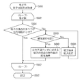
図6は、格子内色予測器生成工程の制御の流れを示すフローチャートである。格子内色予測器生成工程では、格子ごとに処理が実行されるので、格子数でループ処理される(ステップS82)。図3に示す2次元色空間は9つの格子(18‐1から18‐9)に分割されているので、ループ数は9となる。 FIG. 6 is a flowchart showing the control flow of the intra-grid color predictor generation step. In the intra-grid color predictor generation step, the process is executed for each grid, so that a loop process is performed with the number of grids (step S82). Since the two-dimensional color space shown in FIG. 3 is divided into nine grids (18-1 to 18-9), the number of loops is nine.
また、格子内色予測器生成工程では、原点に近い格子から順に処理が実行される。図3に示す色空間では、格子18‐1,格子18‐2,格子18‐3,…,格子18‐8,格子18‐9の順に処理が実行される。 In the intra-grid color predictor generation step, processing is executed in order from the grid closest to the origin. In the color space shown in FIG. 3, the processing is executed in the order of lattice 18-1, lattice 18-2, lattice 18-3,..., Lattice 18-8, and lattice 18-9.
図6のステップS84において、処理対象の格子の頂点のすべてが出力可能パッチであるか否か(既知の測色値を有する頂点であるか否か)が判断される。ステップS84において、処理対象の格子の頂点のすべてが出力可能パッチである場合は(Yes判定)、当該格子のループは終了される。 In step S84 in FIG. 6, it is determined whether or not all of the vertices of the processing target grid are outputable patches (whether or not they are vertices having known colorimetric values). In step S84, when all the vertices of the grid to be processed are output-capable patches (Yes determination), the loop of the grid is terminated.
図3に図示した2次元色空間において、格子18‐1,18‐2,18‐3,18‐4及び格子18‐6は、すべての頂点が出力可能パッチに対応している。 In the two-dimensional color space illustrated in FIG. 3, all of the vertices of the lattices 18-1, 18-2, 18-3, and 18-4 and the lattice 18-6 correspond to output-capable patches.
一方、ステップS84において処理対象の格子に出力不可パッチに対応する頂点がある場合は(No判定)、当該処理対象格子が補外演算可能であるか否かが判断される(ステップS86)。図3に図示した2次元色空間では、格子18‐5,18‐7,18‐8及び格子18‐9は、出力不可パッチに対応する頂点を有している。 On the other hand, if there is a vertex corresponding to the non-outputable patch in the processing target grid in step S84 (No determination), it is determined whether or not the processing target grid can be extrapolated (step S86). In the two-dimensional color space illustrated in FIG. 3, the grids 18-5, 18-7, 18-8, and the grid 18-9 have vertices corresponding to non-outputable patches.
ここで、「補外演算」とは、処理対象の格子に属する補外演算用学習データを用いて、当該処理対象格子における出力不可パッチに対応する頂点の測色値を算出する演算である(詳細後述)。 Here, the “extrapolation calculation” is an operation for calculating the colorimetric values of the vertices corresponding to the non-outputable patches in the processing target grid using the extrapolation learning data belonging to the processing target grid ( Details will be described later).
ステップS86において、処理対象の格子が補外演算用学習データを有し、当該処理対象格子が補外演算可能であると判断されると(YES判定)、ステップS88に進み、補外演算が実行される。一方、ステップS86において、処理対象の格子が補外演算用学習データを有しておらず、当該処理対象格子が補外演算を施すことができない格子であると判断されると(No判定)、格子領域拡大処理(詳細後述)が実行され(ステップS90)、ステップS86に戻り、領域が拡大された処理対象の格子が補外演算可能であるか否かが判断される。 In step S86, if it is determined that the processing target grid has learning data for extrapolation and that the processing target grid can be extrapolated (YES determination), the process proceeds to step S88, and extrapolation is performed. Is done. On the other hand, if it is determined in step S86 that the grid to be processed does not have extrapolation learning data and the grid to be processed cannot be subjected to extrapolation (No determination). A lattice area enlargement process (described later in detail) is executed (step S90), and the process returns to step S86 to determine whether or not the process target lattice whose area has been enlarged can be extrapolated.
すなわち、処理対象の格子が補外演算を施すことができない格子であると、補外演算を施すことができるまで処理対象の格子の領域が拡大され、当該処理対象格子の出力不可パッチに対応する頂点の測色値が算出される。 That is, if the grid to be processed is a grid that cannot be subjected to extrapolation, the area of the grid to be processed is expanded until the extrapolation can be performed, and this corresponds to the non-outputable patch of the target grid. Vertex colorimetric values are calculated.
すべての格子について、出力不可パッチに対応する頂点の測色値が算出されると、格子内色予測器生成工程は終了される(ステップS92)。 When the colorimetric values of the vertices corresponding to the non-outputable patches are calculated for all the grids, the intra-grid color predictor generation process is ended (step S92).
<補外演算の具体例>
次に、図6のステップS88に示した補外演算の具体例について、図3に図示した2次元色空間を例に挙げて説明する。図7は、補外演算の説明図である。なお、図7に図示した色空間は図3に図示した2次元色空間と同一であり、図7中、図3と同一又は類似する部分には同一の符号を付し、その説明は省略する。
<Specific example of extrapolation>
Next, a specific example of the extrapolation calculation shown in step S88 of FIG. 6 will be described using the two-dimensional color space shown in FIG. 3 as an example. FIG. 7 is an explanatory diagram of extrapolation calculation. The color space shown in FIG. 7 is the same as the two-dimensional color space shown in FIG. 3. In FIG. 7, the same or similar parts as in FIG. .
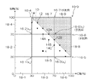
図7に図示した2次元色空間における格子18‐5(太線を用いて図示)は、出力不可パッチに対応する頂点16‐6が含まれている。格子18‐5内の任意の点における測色値をxは、頂点16‐1の測色値xw、頂点16‐2の測色値xm、頂点16‐3の測色値xc、頂点16‐4の測色値xbを用いて、次式(3)で表される。 A lattice 18-5 (shown using a thick line) in the two-dimensional color space illustrated in FIG. 7 includes a vertex 16-6 corresponding to a non-outputable patch. X colorimetric value at any point in the grid 18-5, colorimetric values of a vertex 16-1 x w, colorimetric values of a vertex 16-2 x m, colorimetric values x c of the vertex 16-3, Using the colorimetric value xb of the vertex 16-4, it is expressed by the following equation (3).
x=aw×xw+am×xm+ac×xc+ab×xb …(3)
ここで、aw、am、ac、abは多色相対実効網点面積率であり、デミシェルの公式(式4‐1から式4‐4)を用いて計算される。
x = a w × x w + a m × x m + a c × x c + a b × x b ... (3)
Here, a w , a m , a c , and a b are multicolor relative effective halftone dot area ratios, which are calculated using the Demichel formulas (Equations 4-1 to 4-4).
aw=(1−sc)×(1−sm) …(4‐1)
am=sc×(1−sm) …(4‐2)
ac=(1−sc)×sm …(4‐3)
ab=sc×sm …(4‐4)
scは測色値xの予測対象点におけるシアン軸座標の単色相対実効網点面積率であり、smは測色値xの予測対象点におけるマゼンタ軸座標の単色相対実効網点面積率である。sc、smはそれぞれ、シアン軸座標値、マゼンダ軸座標値から、先に説明した単色ドットゲイン補正曲線を用いて算出される。
a w = (1-s c ) × (1-s m ) (4-1)
a m = s c × (1−s m ) (4-2)
a c = (1−s c ) × s m (4-3)
a b = s c × s m (4-4)
s c is the monochromatic relative effective area coverage of cyan axis coordinate in the prediction target point of colorimetric values x, s m monochromatic relative effective area coverage of magenta-axis coordinate in the prediction target point of colorimetric values x is there. s c, s m respectively, cyan-axis coordinate value, a magenta-axis coordinate value is calculated using the single-color dot gain correction curves described earlier.
格子18‐5において、頂点16‐6は出力不可パッチに対応しているので測色値は未知であるものの、補外演算用学習データ12A,12B,14A,14B,14Cが含まれているので、これらの値を上記式(3)に代入して頂点16‐6の測色値を算出しうる。
In the lattice 18-5, since the vertex 16-6 corresponds to the non-outputable patch, the colorimetric value is unknown, but the extrapolation
図7に示す例では、格子18‐5内に5つの補外演算用学習データ(既知の測色値)12A,12B,14A,14B,14Cが含まれているので、1つの未知数に対して5つの式を立てることができる。そうすると、未知数よりも式数が多い、いわゆる良設定問題となるために最小二乗法によって、誤差が最も小さくなるxbの値を推定しうる。 In the example shown in FIG. 7, five extrapolation calculation learning data (known colorimetric values) 12A, 12B, 14A, 14B, and 14C are included in the lattice 18-5. Five formulas can be established. Then, since it becomes a so-called good setting problem in which the number of formulas is larger than the unknown, the value of xb with the smallest error can be estimated by the least square method.
すなわち、図1に示すパッチ画像作成工程において、出力不可パッチに対応する頂点(未知の測色値を有する頂点)の数よりも多い数のパッチが補外演算用学習部に含まれるように、第2パッチ群を作成しておくことで、上記式(3)を用いた最小二乗法等の手法を用いて、出力不可パッチに対応する頂点の測色値を算出しうる。補外演算用学習部のパッチ数をより多く登録しておくことにより、上記した測色値推定の精度を高めることができる。 That is, in the patch image creation step shown in FIG. 1, the extrapolation calculation learning unit includes a larger number of patches than the number of vertices (vertices having unknown colorimetric values) corresponding to the non-outputable patches. By creating the second patch group, the colorimetric values of the vertices corresponding to the non-outputable patch can be calculated using a method such as the least square method using the above equation (3). By registering a larger number of patches in the extrapolation calculation learning unit, it is possible to improve the accuracy of the colorimetric value estimation described above.
図7に示す格子18‐7及び格子18‐8は、未知の測色値を有する頂点の数(1つ)を超える数の既知の測色値(5つ)が含まれるので、格子18‐7の頂点16‐7の測色値、及び格子18‐8の頂点16‐8の測色値は、上記した格子18‐5の頂点16‐6と同様に、上記式(3)を用いた最小二乗法により測色値を推定しうる。 Since the grid 18-7 and the grid 18-8 shown in FIG. 7 include the number of known colorimetric values (five) exceeding the number of vertices (one) having unknown colorimetric values, the grid 18- As with the vertex 16-6 of the grid 18-5, the above equation (3) was used for the colorimetric value of the vertex 16-7 of the grid 7 and the colorimetric value of the vertex 16-8 of the grid 18-8. The colorimetric value can be estimated by the least square method.
補外演算用学習データ12が色材使用制限値を表す線上に等間隔に整列するように、補外演算用学習部のパッチが作成される態様が好ましい。また、補外演算用学習データ14が色材使用制限値の変動に対応した位置に配置されるように、補外演算用学習部のパッチが作成される態様が好ましい。
A mode in which patches of the extrapolation calculation learning unit are created so that the extrapolation
かかる態様によれば、色材使用制限値が変動する範囲内に既知の測色値である補外演算用学習データ14が存在することで、色材使用制限値の変動範囲内の測色値推定の精度が向上する。
According to this aspect, since the extrapolation
<格子領域拡大処理>
次に、図6のステップS90に図示した格子領域拡大処理について、図3に図示した2次元色空間を例に挙げて説明する。図8は、図3に図示した2次元色空間における格子領域拡大処理の説明図である。なお、図8中、図3及び図7と同一又は類似する部分には同一の符号を付し、その説明は省略する。
<Lattice area expansion processing>
Next, the lattice area expansion process illustrated in step S90 of FIG. 6 will be described using the two-dimensional color space illustrated in FIG. 3 as an example. FIG. 8 is an explanatory diagram of a lattice area expansion process in the two-dimensional color space illustrated in FIG. 8 that are the same as or similar to those in FIGS. 3 and 7 are given the same reference numerals, and descriptions thereof are omitted.
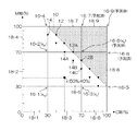
図8に示す2次元色空間において、格子18‐9は補外演算により測色値が求められた頂点16‐6,16‐7,16‐8が含まれており、さらに、未知の測色値を有する頂点16‐9が含まれる。 In the two-dimensional color space shown in FIG. 8, the lattice 18-9 includes vertices 16-6, 16-7, and 16-8 whose colorimetric values are obtained by extrapolation, and further, an unknown colorimetry Vertex 16-9 having a value is included.
また、格子18‐9は、補外演算用学習データ12,14が含まれていないので、既知の測色値を上記式(3)のxに代入して未知の測色値を求める式を立てることができない。
In addition, since the grid 18-9 does not include the extrapolation
すなわち、未知数1、式数0の不良設定問題となり、このままでは頂点16‐9の測色値を推定することができない。かかる場合は、補外演算用学習データ12,14が含まれるように、隣接する格子を連結させて処理対象の格子の領域を拡大させる。
That is, it becomes a defect setting problem of unknown 1 and expression 0, and the colorimetric value of vertex 16-9 cannot be estimated as it is. In such a case, adjacent grids are connected to expand the grid area to be processed so that extrapolation
図8に示す例では、格子18‐9に格子18‐5,18‐6,18‐7を連結させた格子18‐10(太線を用いて図示)を処理対象の格子とする。 In the example shown in FIG. 8, a lattice 18-10 (illustrated using a thick line) in which lattices 18-5, 18-6, and 18-7 are connected to the lattice 18-9 is a processing target lattice.
かかる拡大格子18‐10は、補外演算用学習データ12が6つ、補外演算用学習データ14が7つ含まれるので良設定問題となり、頂点16‐9の測色値を推定することができる。
Such an expanded grid 18-10 is a good setting problem because it includes six extrapolation
すなわち、測色値の推定問題が良設定問題となるまで、格子領域拡大処理を繰り返すことにより、未知の測色値を有する頂点の測色値を補外演算により推定しうる。格子領域拡大処理を考慮して、補外演算用学習データ12及び補外演算用学習データ14に対応するパッチを作成するとよい。
That is, by repeating the grid area enlargement process until the colorimetric value estimation problem becomes a good setting problem, the colorimetric values of vertices having unknown colorimetric values can be estimated by extrapolation. In consideration of the lattice area expansion processing, it is preferable to create patches corresponding to the extrapolation
図9は、格子内色予測器が生成された後の、図3等に図示した2次元色空間を図示した説明図である。図9に示すように、2次元色空間の全域における格子の頂点の測色値が推定されると、色材使用制限値を超える領域についても、入力信号値に対する測色値が予測可能となる。 FIG. 9 is an explanatory diagram illustrating the two-dimensional color space illustrated in FIG. 3 and the like after the intra-grid color predictor is generated. As shown in FIG. 9, when the colorimetric values of the vertices of the grid in the whole area of the two-dimensional color space are estimated, the colorimetric values for the input signal values can be predicted even in the region exceeding the color material usage limit value. .
以上説明した2次元色空間は、多次元色空間に一般化することができる。例えば、CMYK4色を用いた画像形成(4次元色空間)では、上記式(3)は次式(5)のように表される。 The two-dimensional color space described above can be generalized to a multidimensional color space. For example, in image formation (four-dimensional color space) using four colors of CMYK, the above equation (3) is expressed as the following equation (5).
x=aw×xw+ac×xc+am×xm+ay×xy+ak×xk+acm×xcm+acy×xcy+ack×xck+amy×xmy+amk×xmk+ayk×xyk+acmy×xcmy+acyk×xcyk+amyk×xmyk+acmyk×xcmyk …(5)
また、CMYK4色を用いた画像形成では、上記式(4‐1から4‐4)は次式(6‐1から6‐16)のように表される。
x = a w × x w + a c × x c + a m × x m + a y × x y + a k × x k + a cm × x cm + a cy × x cy + a ck × x ck + a my × x my + a mk × x mk + a yk × x yk + a cmy × x cmy + a cyk × x cyk + a myk × x myk + a cmyk × x cmyk (5)
In the image formation using CMYK four colors, the above equations (4-1 to 4-4) are expressed as the following equations (6-1 to 6-16).
aw=(1−sc)×(1−sm)×(1−sy)×(1−sk) …(6‐1)
ac=sc×(1−sm)×(1−sy)×(1−sk) …(6‐2)
am=(1−sc)×sm×(1−sy)×(1−sk) …(6‐3)
ay=(1−sc)×(1−sm)×sy×(1−sk) …(6‐4)
ak=(1−sc)×(1−sm)×(1−sy)×sk …(6‐5)
acm=sc×sm×(1−sy)×(1−sk) …(6‐6)
acy=sc×(1−sm)×sy×(1−sk) …(6‐7)
ack=sc×(1−sm)×(1−sy)×sk …(6‐8)
amy=(1−sc)×sm×sy×(1−sk) …(6‐9)
amk=(1−sc)×sm×(1−sy)×sk …(6‐10)
ayk=(1−sc)×(1−sm)×sy×sk …(6‐11)
acmy=sc×sm×sy×(1−sk) …(6‐12)
acmk=sc×sm×(1−sy)×sk …(6‐13)
acyk=sc×(1−sm)×sy×sk …(6‐14)
amyk=(1−sc)×sm×sy×sk …(6‐15)
acmyk=sc×sm×sy×sk …(6‐16)
すなわち、CMYK4色を用いた画像形成では、格子の頂点が16個になり、上記式(5)、式(6‐1)から式(6‐16)を用いて、測色値の推定が可能となる。
aw = (1-s c ) × (1-s m ) × (1-s y ) × (1-s k ) (6-1)
a c = s c × (1−s m ) × (1−s y ) × (1−s k ) (6-2)
a m = (1-s c ) × s m × (1-s y ) × (1-s k ) (6-3)
a y = (1-s c ) × (1-s m) × s y × (1-s k) ... (6-4)
a k = (1-s c ) × (1-s m ) × (1-s y ) × s k (6-5)
a cm = s c × s m × (1-s y) × (1-s k) ... (6-6)
a cy = s c × (1−s m ) × s y × (1−s k ) (6-7)
a ck = s c × (1-s m ) × (1-s y ) × s k (6-8)
a my = (1-s c ) × s m × s y × (1-s k ) (6-9)
a mk = (1-s c ) × s m × (1-s y ) × s k (6-10)
a yk = (1-s c ) × (1-s m ) × s y × s k (6-11)
a cmy = s c × s m × s y × (1-s k ) (6-12)
a cmk = s c × s m × (1-s y ) × s k (6-13)
a cyk = s c × (1−s m ) × s y × s k (6-14)
a myk = (1-s c ) × s m × s y × s k (6-15)
a cmyk = s c × s m × s y × s k (6-16)
In other words, in image formation using CMYK four colors, there are 16 lattice vertices, and colorimetric values can be estimated using the above equations (5) and (6-1) to (6-16). It becomes.
〔色変換LUT作成工程〕
図1のステップS18において、出力色予測器が生成されると、該出力色予測器を用いて、多次元色空間における色変換関係が求められる。すなわち、出力色予測器を用いて、任意の入力信号値を出力される色(色値)に変換する色変換LUTを作成することができる。
[Color conversion LUT creation process]
When an output color predictor is generated in step S18 of FIG. 1, a color conversion relationship in a multidimensional color space is obtained using the output color predictor. That is, it is possible to create a color conversion LUT that converts an arbitrary input signal value to an output color (color value) using an output color predictor.
以下に、図1のステップS20に示す色変換LUT作成工程について詳説する。 Hereinafter, the color conversion LUT creation process shown in step S20 of FIG. 1 will be described in detail.
印刷分野では、CMS(Color Management System)処理による色合せを行う際に、一旦、装置に依存した色信号値であるデバイス依存色から、装置に依存しない色信号値であるデバイス非依存色に変換するための、いわゆるA2Bテーブルを作成することが行われている。 In the printing field, when color matching is performed by CMS (Color Management System) processing, a device-dependent color that is a color signal value dependent on the device is once converted into a device-independent color that is a color signal value independent of the device. In order to do so, a so-called A2B table is created.
図1のステップS18で生成された出力色予測器を用いて予測される測色値は、デバイス非依存色に他ならないので、出力色予測器はCMS処理に適用することが可能である。 Since the colorimetric value predicted using the output color predictor generated in step S18 of FIG. 1 is nothing but a device-independent color, the output color predictor can be applied to CMS processing.
一方、印刷装置(画像形成装置)に入力される画像データの1画素ごとの測色値を、出力色予測器で1画素ずつ予測すると、データ処理時間が大きくなってしまう。また、CMS処理を行うRIP(Raster Image Processor)機器では、色変換に統一された規格であるICC(International Color Consortium)プロファイルが用いられることが多いので、色変換処理に使用される色変換LUTを別途用意して、ICCプロファイルに組み込むといった運用を行うことが現実的である。 On the other hand, if the colorimetric value for each pixel of the image data input to the printing apparatus (image forming apparatus) is predicted pixel by pixel by the output color predictor, the data processing time is increased. In addition, in an RIP (Raster Image Processor) device that performs CMS processing, an ICC (International Color Consortium) profile that is a standard standard for color conversion is often used. Therefore, a color conversion LUT used for color conversion processing is used. It is practical to prepare separately and incorporate it into the ICC profile.
そこで、本実施形態に示す色変換LUT作成工程では、色変換LUT(A2Bテーブル)が作成される。「A2Bテーブル」は、デバイス依存色空間(例えばCMYK値)からデバイス非依存色空間(例えば、CIE−XYZ値やL*a*b*値)へ変換するためのLUTであり、多次元デバイス依存色空間を離散化させた格子に分割し、予測対象点(LUT格子点)の測色値が格納されたテーブルである。 Therefore, in the color conversion LUT creation process shown in this embodiment, a color conversion LUT (A2B table) is created. The “A2B table” is an LUT for converting from a device-dependent color space (for example, CMYK values) to a device-independent color space (for example, CIE-XYZ values or L * a * b * values). It is a table in which the color space is divided into discrete grids and the colorimetric values of the prediction target points (LUT grid points) are stored.
(A2Bテーブルの作成)
図10は、出力色予測器を用いた色変換LUT(A2Bテーブル)の作成処理の流れを示すフローチャートである。以下に説明するA2Bテーブル作成は、LUT格子点ごとに繰り返し行われる(ステップS102)。まず、LUT格子点の色信号値(例えば、CMYK値)が属する、出力色予測器における格子が探索される(ステップS104)。
(Create A2B table)
FIG. 10 is a flowchart showing a flow of processing for creating a color conversion LUT (A2B table) using an output color predictor. The A2B table creation described below is repeated for each LUT lattice point (step S102). First, a grid in the output color predictor to which the color signal value (for example, CMYK value) of the LUT grid point belongs is searched (step S104).
例えば、CM2色印刷(図9に示す2次元色空間)で、入力色信号値が(C,M)=(50%,40%)の場合は、格子18‐5が探索される。次に、選択された出力色予測器の格子18‐5の頂点16‐1,16‐2,16‐3,16‐4の測色値(xw,xm,xc,xb)と、入力色信号値から計算される前述した多色相対実効網点面積率から、上記式(3)を用いて測色値が予測され(ステップS106)、LUTに適用される。 For example, in the case of CM two-color printing (two-dimensional color space shown in FIG. 9), when the input color signal value is (C, M) = (50%, 40%), the grid 18-5 is searched. Next, the colorimetric values (x w , x m , x c , x b ) of the vertices 16-1, 16-2, 16-3, 16-4 of the selected output color predictor grid 18-5 and The colorimetric value is predicted from the above-described multi-color relative effective halftone dot area ratio calculated from the input color signal value using the above equation (3) (step S106) and applied to the LUT.
以上の処理で色変換LUTを作成することができる。出力色予測器は、色材使用制限値を超えた領域を含む任意の入力色信号値(デバイス依存カラー)を予測することができるため、A2Bテーブルもデバイス依存色空間全域におけるLUTを作成することができる。 The color conversion LUT can be created by the above processing. Since the output color predictor can predict an arbitrary input color signal value (device-dependent color) including a region exceeding the color material usage limit value, the A2B table also creates an LUT in the entire device-dependent color space. Can do.
(B2Aテーブルの作成)
CMS処理では、デバイス依存色空間からデバイス非依存色空間への変換を行うA2Bテーブルの他に、A2Bテーブルの逆写像、つまり、デバイス非依存色空間からデバイス依存色空間への変換を行うB2Aテーブルも必要になる。
(Create B2A table)
In the CMS processing, in addition to the A2B table for converting from the device-dependent color space to the device-independent color space, the reverse mapping of the A2B table, that is, the B2A table for converting from the device-independent color space to the device-dependent color space Is also required.
本実施形態に示す色変換LUT作成工程では、B2Aテーブルが作成される。デバイス依存色空間としてCMYKの4つの信号値、デバイス非依存色空間にCIE−XYZ値を用いる場合を例に説明する。 In the color conversion LUT creation process shown in this embodiment, a B2A table is created. An example will be described in which four CMYK signal values are used as the device-dependent color space and CIE-XYZ values are used in the device-independent color space.
B2Aテーブルの作成は、LUT格子点ごとに繰り返し行われる(ステップS102)。先に説明したA2Bテーブルは、1つのCMYK値の組み合わせに対して1つのXYZ値の組み合わせが定義できるが、B2Aテーブルでは、例えば、グレー系の色はKインクを用いて表現することもできれば、CMYインクを組み合わせてプロセスブラックを用いて表現することもできるため、予め使用インクの分配方法を設定する必要がある(ステップS124)。 The creation of the B2A table is repeated for each LUT lattice point (step S102). In the A2B table described above, one combination of XYZ values can be defined for one combination of CMYK values. However, in the B2A table, for example, if a gray color can be expressed using K ink, Since CMY inks can be combined and expressed using process black, it is necessary to set a method for distributing the used ink in advance (step S124).
かかる使用インクの分配方法には、公知の技術を適用することができるので、ここでは詳細な説明を省略する。 Since a known technique can be applied to the method of distributing the ink used, detailed description thereof is omitted here.
次に、インクジェット方式の画像形成や、電子写真方式の画像形成のように、使用可能な色材の総量に制限がある場合は、その制限値を設定する必要がある(ステップS126)。予め設定された制限値(制約条件)を用いて、CIE−XYZ色空間を格子状に分割し、各LUT格子点に対して、その色を実現するCMYK値を探索することでB2Aテーブルを作成する(ステップS128)。 Next, when there is a limit to the total amount of color material that can be used, such as inkjet image formation or electrophotographic image formation, it is necessary to set the limit value (step S126). Create a B2A table by dividing the CIE-XYZ color space into a grid using preset limit values (constraints) and searching for CMYK values that realize that color for each LUT grid point (Step S128).
なお、インク総量の制限値には、例えば、先に説明した色材使用値を設定してもよいが、本実施形態では、A2BテーブルのCMYK空間の全領域の色が求められているため、インク総量の制限値に任意の値を設定することができる。 For example, the color material usage value described above may be set as the limit value of the total amount of ink. However, in this embodiment, since the colors of all areas in the CMYK space of the A2B table are obtained, An arbitrary value can be set as the limit value of the total ink amount.
例えば、単色理論網点面積率(%)ではなく、インクの物理量(例えば、体積)を設定してもよいし、色材使用制限値を超える色材量が使用可能であることがわかった際には、後からインク総量制限値を微調整してB2Aテーブルを作り直すといった柔軟な処理が可能となる。 For example, instead of the monochromatic theoretical halftone dot area ratio (%), the physical quantity (for example, volume) of the ink may be set, or when it is found that the color material amount exceeding the color material use limit value can be used. Then, it is possible to perform flexible processing such as re-adjusting the total ink amount limit value and recreating the B2A table later.
なお、ここでいう「B2Aテーブルの作り直し」は、あくまでコンピュータに再計算をさせるだけであり、チャートの再作成や再出力・再測定といった手間のかかる工程は一切必要ない。 Note that the “re-creation of the B2A table” here simply causes the computer to recalculate, and no time-consuming steps such as chart re-creation, re-output, and re-measurement are required.
上記の如く構成された色予測方法によれば、色材総使用量に制限がある画像形成装置及び記録媒体の組み合わせについて、予め正確な色材使用制限値がわかっておらず曖昧性が残されていた場合でも、擬似的に仮の色材使用制限値が設定され、出力色予測器を生成することができ、仮の色材使用制限値を超えた入力信号値を含んだ任意の入力信号値に対する色を予測(変換)できる。 According to the color prediction method configured as described above, an accurate color material usage limit value is not known in advance for the combination of an image forming apparatus and a recording medium with a limited total color material usage amount, and ambiguity remains. Even if it is, a temporary color material use limit value is set in a pseudo manner, an output color predictor can be generated, and an arbitrary input signal including an input signal value exceeding the temporary color material use limit value Predict (convert) the color for the value.
また、実際の色材使用制限値が仮の色材使用制限値よりも大きいことがわかった場合でも、チャートの再作成、再出力、再測定、LUTの作り直しをせずに、既に生成された出力色予測器を用いて、計算のみで実際の色材使用制限値に対する色変換テーブルを作成できる。 Even if it is found that the actual color material usage limit value is larger than the temporary color material usage limit value, it has already been generated without re-creating the chart, re-outputting, re-measurement, or recreating the LUT. Using the output color predictor, a color conversion table for the actual color material use limit value can be created only by calculation.
例えば、より厚い記録媒体を用いるなど、実際の色材使用制限値が変化した場合でも、既存の出力色予測器を用いて、計算のみで、新たな色材使用制限値に対する色変換テーブルを作成できる。 For example, even if the actual color material usage limit value has changed, such as using a thicker recording medium, a color conversion table for a new color material usage limit value can be created only by calculation using the existing output color predictor. it can.
さらに、デバイス非依存色空間からデバイス依存色空間に変換を行う、いわゆるB2Aテーブルを作成する際の探索条件に任意のインク総量制限値を設定することができる。 Furthermore, an arbitrary total ink amount limit value can be set as a search condition when creating a so-called B2A table for converting from a device-independent color space to a device-dependent color space.
以上説明した色予測方法の各工程をコンピュータに実行させるプログラムとすることが可能である。すなわち、該プログラムを所定の記憶媒体へ記憶しておき、該記憶媒体へ記憶させたプログラムをコンピュータに読み込ませて、色予測方法の各工程を実行可能である。 A program for causing a computer to execute each step of the color prediction method described above can be provided. That is, each step of the color prediction method can be executed by storing the program in a predetermined storage medium and reading the program stored in the storage medium into a computer.
〔色予測システムへの適用例〕
次に、本発明の実施形態に係る色予測方法が適用される色予測システムについて説明する。図12は、本発明の実施形態に係る色予測システムの全体構成図である。
[Example of application to color prediction system]
Next, a color prediction system to which the color prediction method according to the embodiment of the present invention is applied will be described. FIG. 12 is an overall configuration diagram of the color prediction system according to the embodiment of the present invention.
同図に示す色予測システム100は、パッチ群(チャート画像)を出力させるインクジェット記録装置102と、インクジェット記録装置102により出力されたパッチ群を測色する分光光度計104と、分光光度計104により得られた測色情報を取得して、出力色予測器を生成し、色予測(色変換)LUTを作成し、該色予測LUT所定の記憶装置に格納する画像処理装置106と、画像処理装置106の出力装置及び入力装置として機能するタッチパネル色のモニタ装置108と、画像処理装置106の入力装置として機能するマウス110と、を含んで構成される。
The
図12に示す色予測システム100の各部は、データ通信用の有線ケーブルにより接続されている。なお、データ通信には無線形式を適用してもよい。
Each part of the
画像処理装置106は、色予測LUTが記憶される記憶装置が含まれる。なお、画像処理装置106に内蔵される記憶装置とは別に、色予測LUTが記憶される記憶装置が設けられていてもよい。
The
なお、画像処理装置106は、任意の入力信号値に対して色予測LUTを参照しながら色予測処理(色変換処理)を施す処理部として機能してもよいし、色予測LUTを作成する各工程を実行して、任意の入力信号値に対して演算等を用いて色予測LUTを参照せずに色予測処理を施す処理部として機能してもよい。
Note that the
図13は、図12に示す色予測システムのブロック図である。同図に示すように、色予測システム100の各部は、制御部120によって統括制御される。
FIG. 13 is a block diagram of the color prediction system shown in FIG. As shown in the figure, each part of the
色材使用制限値設定部122は、出力色予測器124を生成するための仮の色材使用制限値を設定する。この設定値は所定の記憶部(例えば、図13のメモリ126)に記憶される。
The color material use limit
チャート画像作成部128は、予め記憶されている仮の色材使用制限値を参照して、チャート画像出力部として機能するインクジェット記録装置102から出力させるチャート画像を作成する。
The chart
演算処理部130は、測色部として機能する分光光度計104の測色結果に基づいて、出力色予測器124を生成するとともに、出力色予測器124を用いて生成された色予測(色変換)LUTを生成する。色予測(色変換)LUTは、LUT格納部132に格納される。
The
入出力インターフェース(入出力I/F)134は、図2のタッチパネル式モニタ装置108、マウス110が含まれる。なお、USB(Universal Serial Bus)なとの他の汎用インターフェースを含んでいてもよい。
The input / output interface (input / output I / F) 134 includes the
〔画像処理システムへの適用例〕
本例に示す色予測方法は、インクジェット記録装置(画像形成装置)の内部で、画像処理の一環として実行してもよい。例えば、インクジェット記録装置のメンテナンスの一部として、色予測方法により作成された色予測LUTを装置内に読み込んでもよい。
[Example of application to image processing system]
The color prediction method shown in this example may be executed as part of image processing inside an ink jet recording apparatus (image forming apparatus). For example, the color prediction LUT created by the color prediction method may be read into the apparatus as part of maintenance of the ink jet recording apparatus.
例えば、インクジェットヘッドの交換や、描画エンジンの交換が生じた場合には、チャート画像作成、チャート画像出力、測色結果に基づく色変換LUTの作成(更新)をインクジェット記録装置内で実行してもよい。また、色変換処理をインクジェット記録装置内の画像処理の一部として実行してもよい。 For example, when an inkjet head exchange or drawing engine exchange occurs, chart image creation, chart image output, and creation (update) of a color conversion LUT based on the color measurement result may be executed in the inkjet recording apparatus. Good. Further, the color conversion process may be executed as part of the image process in the ink jet recording apparatus.
(インクジェット記録装置の概略構成)
図14は、本例に示す色予測方法により作成された色予測LUTが適用されるインクジェット記録装置の概略構成図である。同図に示すインクジェット記録装置200は、オンデマンド型インクジェット記録装置であり、記録媒体212を保持搬送する記録媒体搬送部214と、CMYKの各色に対応するインクジェットヘッド216C,216M,216Y,216Kを含む描画部217と、を含んで構成される。
(Schematic configuration of inkjet recording apparatus)
FIG. 14 is a schematic configuration diagram of an ink jet recording apparatus to which a color prediction LUT created by the color prediction method shown in this example is applied. The ink
記録媒体搬送部214は、記録媒体212が保持される記録媒体保持領域に多数の吸着穴(不図示)が設けられた無端状の搬送ベルト218と、搬送ベルト218が巻き掛けられる搬送ローラ(駆動ローラ220、従動ローラ222)と、記録媒体保持領域の搬送ベルト218の裏側(記録媒体212が保持される記録媒体保持面と反対側の面)に設けられ、記録媒体保持領域に設けられた不図示の吸着穴にと連通しているチャンバー224と、チャンバー224に負圧を発生させる真空ポンプ226と、を含んでいる。
The recording
記録媒体212が搬入される搬入部228には、記録媒体212の浮きを防止するための押圧ローラ230が設けられるとともに、記録媒体212が排出される排出部232にもまた、押圧ローラ234が設けられている。
The carry-in
搬入部228から搬入された記録媒体212は、記録媒体保持領域に設けられた吸着穴から負圧が付与され、搬送ベルト218の記録媒体保持領域に吸着保持される。
The
記録媒体212の搬送路上には、描画部217の前段側(記録媒体搬送方向上流側)に、記録媒体212の表面温度を所定範囲に調整するための温度調節部236が設けられるとともに、描画部217の後段側(記録媒体搬送方向下流側)に、記録媒体212上に記録された画像を読み取る読取装置(読取センサ)238が設けられている。
On the conveyance path of the
図14に示すように、インクジェットヘッド216C,216M,216Y,216Kは、記録媒体搬送方向の上流側からこの順番で配置されている。記録媒体212がインクジェットヘッド216C,216M,216Y,216Kの直下を通過する際に、記録媒体212に対してKCMYの各色のインクを吐出させて、所望のカラー画像が形成される。
As shown in FIG. 14, the inkjet heads 216C, 216M, 216Y, and 216K are arranged in this order from the upstream side in the recording medium conveyance direction. When the
なお、描画部217は上述した形態に限定されない。例えば、LC(ライトシアン)やLM(ライトマゼンタ)に対応するインクジェットヘッドを具備してもよい。また、インクジェットヘッド216C,216M,216Y,216Kの配置順も適宜変更可能である。
The
インクジェットヘッド216C,216M,216Y,216Kは、圧電素子のたわみ変形を利用してインクを吐出させる圧電方式が適用されてもよいし、インクの加熱による膜沸騰現象を利用してインクを吐出させるサーマル方式が適用されてもよい。 The inkjet heads 216C, 216M, 216Y, and 216K may be applied with a piezoelectric system that ejects ink by using the flexural deformation of a piezoelectric element, or thermal that ejects ink by using a film boiling phenomenon due to heating of the ink. A scheme may be applied.
圧電方式のインクジェットヘッドの構造例として、インクを吐出させる複数のノズルと、各ノズルと連通する圧力室と、圧力室に設けられた圧電素子と、を備える態様が挙げられる。 As an example of the structure of a piezoelectric ink jet head, there is an aspect including a plurality of nozzles that eject ink, a pressure chamber that communicates with each nozzle, and a piezoelectric element that is provided in the pressure chamber.
また、サーマル方式のインクジェットヘッドは、圧電方式の圧電素子に代わり、圧力室(液室)内のインクを加熱するためのヒータが具備される態様が挙げられる。インクジェットヘッド216C,216M,216Y,216Kのノズル配置は、一列配置、千鳥配置、マトリクス配置などを適用することができる。 In addition, the thermal ink jet head includes an embodiment in which a heater for heating ink in a pressure chamber (liquid chamber) is provided instead of the piezoelectric piezoelectric element. As the nozzle arrangement of the inkjet heads 216C, 216M, 216Y, and 216K, a one-line arrangement, a staggered arrangement, a matrix arrangement, or the like can be applied.
図14には、フルライン型のインクジェットヘッドを備えた構成例を図示したが、シリアル方式のインクジェットヘッドを備えた構成を適用してもよい。 Although FIG. 14 illustrates a configuration example including a full-line type inkjet head, a configuration including a serial type inkjet head may be applied.
〔制御系の説明〕
図15は、インクジェット記録装置200の制御系の概略構成を示すブロック図である。同図に示すように、インクジェット記録装置200は、通信インターフェース250、システム制御部252、搬送制御部254、画像処理部256、ヘッド駆動部258を備えるとともに、画像メモリ260、ROM262を備えている。
[Explanation of control system]
FIG. 15 is a block diagram illustrating a schematic configuration of a control system of the
通信インターフェース250は、ホストコンピュータ264から送られてくるラスター画像データを受信するインターフェース部である。通信インターフェース250は、USB(Universal Serial Bus)などのシリアルインターフェースを適用してもよいし、セントロニクスなどのパラレルインターフェースを適用してもよい。通信インターフェース250は、通信を高速化するためのバッファメモリ(不図示)を搭載してもよい。
The
システム制御部252は、中央演算処理装置(CPU)及びその周辺回路等から構成され、所定のプログラムに従ってインクジェット記録装置200の全体を制御する制御装置として機能するとともに、各種演算を行う演算装置として機能し、さらに、画像メモリ260及びROM262のメモリコントローラとして機能する。
The
すなわち、システム制御部252は、通信インターフェース250、搬送制御部254等の各部を制御し、ホストコンピュータ264との間の通信制御、画像メモリ260及びROM262の読み書き制御等を行うとともに、上記の各部を制御する制御信号を生成する。
That is, the
ホストコンピュータ264から送出された画像データは通信インターフェース250を介してインクジェット記録装置200に取り込まれ、画像処理部256によって所定の画像処理が施される。
Image data sent from the
画像処理部256は、画像データから印字制御用の信号を生成するための各種加工、補正などの処理を行う信号(画像)処理機能を有し、生成した印字データ(ドットデータ)をヘッド駆動部258に供給する制御部である。
The
画像処理部256において所要の信号処理が施されると、該印字データ(ハーフトーン画像データ)に基づいて、ヘッド駆動部258を介してインクジェットヘッド216(インクジェットヘッド216C,216M,216Y,216K)吐出液滴量(打滴量)や吐出タイミングの制御が行われる。
When the required signal processing is performed in the
これにより、所望のドットサイズやドット配置が実現される。なお、図15に示すヘッド駆動部258には、インクジェットヘッド216の駆動条件を一定に保つためのフィードバック制御系を含んでいてもよい。
Thereby, a desired dot size and dot arrangement are realized. Note that the
図15に示す画像処理部256において、先に説明した色予測方法(色変換方法)を適宜適用することができる。ここでいう色予測処理は、色予測LUTを参照するものでもよいし、演算によるものでもよい。
In the
例えば、先に説明した色予測方法(色変換方法)用いて、ハーフトーン処理前の画像データに色変換処理(RGBで表された入力画像データをCMYKに変換する色変換処理)を行うことが可能である。 For example, using the color prediction method (color conversion method) described above, color conversion processing (color conversion processing for converting input image data expressed in RGB into CMYK) is performed on image data before halftone processing. Is possible.
搬送制御部254は、画像処理部256により生成された印字データに基づいて記録媒体212(図1参照)の搬送タイミング及び搬送速度を制御する。図15における搬送駆動部266は、記録媒体212を搬送する記録媒体搬送部214の駆動ローラ220(222)を駆動するモータが含まれており、搬送制御部254は該モータのドライバーとして機能している。
The
画像メモリ(一時記憶メモリ)260は、通信インターフェース250を介して入力された画像データを一旦格納する一時記憶手段としての機能や、ROM262に記憶されている各種プログラムの展開領域及びCPUの演算作業領域(例えば、画像処理部256の作業領域)としての機能を有している。画像メモリ260には、逐次読み書きが可能な揮発性メモリ(RAM)が用いられる。
The image memory (temporary storage memory) 260 functions as temporary storage means for temporarily storing image data input via the
ROM262は、システム制御部252のCPUが実行するプログラムや、装置各部の制御に必要な各種データ、制御パラメータなどが格納されており、システム制御部252を通じてデータの読み書きが行われる。ROM262は、半導体素子からなるメモリに限らず、ハードディスクなど磁気媒体を用いてもよい。また、外部インターフェースを備え、着脱可能な記憶媒体を用いてもよい。
The
パラメータ記憶部268は、インクジェット記録装置200の動作に必要な各種制御パラメータが記憶されている。システム制御部252は、制御に必要なパラメータを適宜読み出すとともに、必要に応じて各種パラメータの更新(書換)を実行する。
The
プログラム格納部270は、インクジェット記録装置200を動作させるための制御プログラムが格納されている記憶手段である。システム制御部252(又は装置各部)は、装置各部の制御を実行する際にプログラム格納部270から必要な制御プログラムが読み出され、該制御プログラムは適宜実行される。
The
プログラム格納部270は、先に説明した色予測方法の各工程を該インクジェット記録装置200に実行させるソフトウエア(プログラム)が格納されてもよい。また、色予測LUTが格納され、システム制御部252を介して画像処理部256が色予測LUTを参照するように構成してもよい。
The
さらに、図15の画像処理部256において、色予測LUTを参照して色変換を実行するプログラムを格納してもよい。
Further, the
入力インターフェース(I/F)274は、キーボード、マウス、ジョイスティックなどの情報入力手段が適用される。入力インターフェース274を介して入力された情報は、システム制御部252へ送出される。
As the input interface (I / F) 274, information input means such as a keyboard, a mouse, and a joystick are applied. Information input via the
図15には図示しないが、システム制御部252から送出される各種情報を表示する手段として表示部を備える形態が好ましい。表示部の一例として、図14に図示したタッチパネル方式のモニタ装置や、LCDモニタなどの汎用ディスプレイ装置が挙げられる。また、スピーカーなどの音(音声)出力部を備えてもよい。
Although not shown in FIG. 15, a mode in which a display unit is provided as means for displaying various information sent from the
図14及び図15に図示した各部は、先に説明した色予測方法、色予測LUT生成方法、画像処理方法の各工程を実行させるハードウエアとして機能させることが可能である。 Each unit illustrated in FIGS. 14 and 15 can function as hardware for executing the steps of the color prediction method, the color prediction LUT generation method, and the image processing method described above.
以上説明した、本発明の実施体に係る色予測方法、色予測LUT生成方法、画像処理方法及び画像処理装置は、本発明の趣旨を逸脱しない範囲で、適宜構成要件を変更、追加、削除することが可能である。 The above-described color prediction method, color prediction LUT generation method, image processing method, and image processing apparatus according to the embodiment of the present invention appropriately change, add, or delete the configuration requirements without departing from the spirit of the present invention. It is possible.
〔付記〕
上記に詳述した発明の実施形態についての記載から把握されるとおり、本明細書は少なくとも以下に示す態様を含む多様な技術思想の開示を含んでいる。
[Appendix]
As will be understood from the description of the embodiments of the invention described in detail above, the present specification includes disclosure of various technical ideas including at least the following aspects.
(第1態様):複数色に対応する多次元の色空間において、仮の色材使用制限値を設定する色材使用制限値設定工程と、予め定められた色材の組み合わせにおける色材使用値の合計値が、設定された使用制限値以下の領域について、定められた色材使用値の組み合わせに基づく複数のパッチを含むパッチ群を作成するパッチ群作成工程と、作成されたパッチ群を媒体へ出力するパッチ群出力工程と、パッチ群を測色する測色工程と、測色された各パッチの測色値に基づき、色材使用制限値を超える領域の仮想的なパッチの測色値を補外演算により推定する測色値推定工程と、測色工程及び測色値推定工程により得られた測色値に基づいて、色空間における色材使用値の組み合わせに対する色を補間演算により
予測する色予測工程と、を含む色予測方法。
(First aspect): In a multidimensional color space corresponding to a plurality of colors, a color material usage limit value setting step for setting a temporary color material usage limit value, and a color material usage value in a predetermined combination of color materials A patch group creating step for creating a patch group including a plurality of patches based on a combination of predetermined color material usage values for an area whose total value is equal to or less than a set use limit value, and the created patch group as a medium Based on the colorimetric values of the patch group output process, the colorimetric process of measuring the patch group, and the measured colorimetric values of each patch, the colorimetric values of the virtual patches in the area exceeding the color material usage limit value A colorimetric value estimation process for estimating color by using extrapolation, and a color for a combination of colorant usage values in a color space is predicted by interpolation based on the colorimetric values obtained by the colorimetry process and the colorimetry value estimation process. A color prediction process to include Way measurement.
かかる態様によれば、色材使用量が制限され、正確な色材使用制限値がわからずに曖昧さが残されていても、擬似的に仮の色材使用制限値が設定され、色材使用制限値を超える領域の仮想的なパッチの測色値が補外演算により推定され、推定された測色値を用いて補間演算により色材使用制限値を超える領域の測色値が予測されるので、色材使用制限値を超えた任意の入力に対する色の予測が可能となる。 According to this aspect, even if the amount of color material used is limited and the ambiguity remains without knowing the exact color material use limit value, a pseudo color material use limit value is set in a pseudo manner, and the color material The colorimetric values of the virtual patches in the area exceeding the usage limit value are estimated by extrapolation, and the colorimetric values in the area exceeding the color material usage limit value are predicted by interpolation using the estimated colorimetric value. Therefore, it is possible to predict a color for an arbitrary input exceeding the color material usage limit value.
また、仮の色材使用制限値周辺領域の測色値は予測精度が特に高いため、色材使用制限値が変更されたとしても、パッチ群作成、パッチ群出力、測色といった一連の処理を行う必要がない。 In addition, since the colorimetric values in the surrounding area of the temporary color material use limit value have a particularly high prediction accuracy, even if the color material use limit value is changed, a series of processes such as patch group creation, patch group output, and color measurement are performed. There is no need to do it.
(第2態様):パッチ群作成工程は、色材使用制限値以下であり、色材使用制限値の測色値又は色材使用制限値の近傍の測色値を有し、測色値推定工程における補外演算に用いられる学習データとして使用される混色の補外演算用パッチ群を作成する補外演算用パッチ群作成工程を含んでいる。 (Second aspect): The patch group creation step is equal to or less than the color material use limit value, has a color measurement value of the color material use limit value , or a color measurement value near the color material use limit value, and estimates the color measurement value An extrapolation calculation patch group creating step of creating a mixed color extrapolation patch group used as learning data used for extrapolation calculation in the process is included.
かかる態様によれば、補外演算用パッチ群の測色結果を用いて、好ましい補外演算が実行される。 According to this aspect, a preferable extrapolation calculation is executed using the colorimetry result of the extrapolation calculation patch group.
色材使用制限値の近傍に色材使用制限値の変動範囲が含まれることで、色材使用制限値の変動範囲における色予測の精度が向上する。 By including the variation range of the color material use restriction value in the vicinity of the color material use restriction value, the accuracy of color prediction in the variation range of the color material use restriction value is improved.
(第3態様):測色値推定工程は、色空間における色材使用制限値を超える領域の基底格子の測色値を、補外演算用パッチ群の測色値を用いて補外演算により予測する基底格子予測工程を含んでいる。 (Third aspect): colorimetric value estimation step, the colorimetric values of the base grating region exceeding colorant use limit value in a color space, by extrapolation calculation using the colorimetric values of the auxiliary outer calculation patch group It includes a base lattice prediction step for prediction.
かかる態様によれば、色材使用制限値を超える領域の基底格子の測色値が予測されるので、色材使用制限値を超える領域の基底格子の測色値を用いた補間演算が実行可能となる。 According to this aspect, since the colorimetric value of the base grid in the area exceeding the color material use limit value is predicted, the interpolation calculation using the color measurement value of the base grid in the area exceeding the color material use limit value can be executed. It becomes.
(第4態様):測色値推定工程は、予め区画された領域ごとに補外演算が実行される。 (Fourth aspect): In the colorimetric value estimation step, an extrapolation calculation is executed for each of the previously partitioned areas.
かかる態様において、原点に近い領域から順に補外演算が実行される態様が好ましい。 In such an aspect, an aspect in which extrapolation calculation is performed in order from an area close to the origin is preferable.
(第5態様):測色値推定工程は、補外演算用パッチ群に対応する学習データが存在しない領域における補外演算を実行する際に、学習データが存在する他の領域が含まれるように、学習データが存在しない領域を拡大させる領域拡大工程を含んでいる。 (Fifth Aspect): The colorimetric value estimation step includes other regions in which the learning data exists when executing the extrapolation calculation in the region in which the learning data corresponding to the extrapolation patch group does not exist. In addition, a region expanding step of expanding a region where no learning data exists is included.
かかる態様によれば、補外演算用パッチ群に対応する学習データが存在しない領域においても、補外演算を実行することが可能となる。 According to this aspect, it is possible to execute the extrapolation calculation even in a region where there is no learning data corresponding to the extrapolation calculation patch group.
(第6態様):パッチ群作成工程は、単色の色材における色材使用量を変化させたときの測色値の変化の非線形性を補正するための単色パッチ群を生成する非線形性補正用パッチ群作成工程を含んでいる。 (Sixth aspect): The patch group creation step is for nonlinearity correction for generating a monochrome patch group for correcting nonlinearity of a change in colorimetric value when a color material usage amount in a monochrome color material is changed. It includes a patch group creation process.
かかる態様によれば、各色の測色値の非線形性が補正され、より正確に色予測をすることが可能となる。 According to this aspect, the nonlinearity of the colorimetric values of each color is corrected, and it becomes possible to perform color prediction more accurately.
かかる態様において、非線形性が強い区間は刻みを細かくすることで、補正精度を向上させることができる。 In such an aspect, the correction accuracy can be improved by making the intervals of the non-linearity finer.
(第7態様):パッチ群作成工程は、色予測工程における補間演算に用いられる基底格子を決めるための混色パッチを生成する補間演算用基底パッチ群作成工程を含んでいる。 (Seventh aspect): The patch group creation step includes an interpolation calculation base patch group creation step for generating a color mixture patch for determining a base grid used for the interpolation calculation in the color prediction step.
かかる態様によれば、基底格子の測色値に基づく好ましい補間演算を実行することが可能となる。 According to this aspect, it is possible to execute a preferable interpolation calculation based on the colorimetric values of the base grid.
(第8態様):複数色は、少なくとも、イエロー、マゼンタ、シアン、及びブラックを含んでいる。 (Eighth aspect): The plurality of colors include at least yellow, magenta, cyan, and black.
かかる態様において、ライトマゼンタ、ライトシアンなどの色を含む態様も可能である。 In such an aspect, an aspect including colors such as light magenta and light cyan is also possible.
(第9態様):色材は、インクジェット方式の画像形成に用いられるカラーインク、又は電子写真方式の画像形成に用いられるトナーに含まれるに着色剤である。 (Ninth aspect): The color material is a colorant contained in a color ink used for ink-jet image formation or a toner used for electrophotographic image formation.
かかる態様によれば、インクジェット方式の画像形成、及び電子写真方式の画像形成に対して本発明に係る色予測方法を適用しうる。 According to this aspect, the color prediction method according to the present invention can be applied to inkjet image formation and electrophotographic image formation.
(第10態様):複数色に対応する多次元の色空間における仮の色材使用制限値を設定する色材使用制限値設定工程と、予め定められた色材の組み合わせにおける色材使用値の合計値が、設定された使用制限値以下の領域について、定められた色材使用値の組み合わせに基づく複数のパッチを含むパッチ群を作成するパッチ群作成工程と、作成されたパッチ群を媒体へ出力するパッチ群出力工程と、パッチ群を測色する測色工程と、測色された各パッチの測色値に基づき、色材使用制限値を超える領域の仮想的なパッチの測色値を補外演算により推定する測色値推定工程と、測色工程及び測色値推定工程により得られた測色値に基づいて、色空間における色材使用値の組み合わせに対する色を補間演算により予測して、色空間における色材使用値の組み合わせに対する色の変換関係を求める色予測工程と、色空間における、定められた複数色の色材使用値の組合せと、予測された色との変換関係を示す色変換ルックアップテーブルを生成する色変換ルックアップテーブル生成工程と、を含む色変換ルックアップテーブル生成方法。 (Tenth aspect): the color material using limit value to set the color material using limit values of the provisional that put the multi-dimensional color space corresponding to a plurality of colors setting step, using color materials in combination colorant predetermined A patch group creation step for creating a patch group including a plurality of patches based on a combination of predetermined color material usage values for an area where the total value is equal to or less than a set usage limit value, and the created patch group Based on the patch group output process to output to the medium, the color measurement process to measure the color of the patch group, and the colorimetric value of each measured color patch, the color measurement of the virtual patch in the area exceeding the color material usage limit value A colorimetric value estimation step for estimating values by extrapolation, and a color for a combination of color material usage values in the color space by interpolation based on the colorimetry values obtained by the colorimetry step and the colorimetry value estimation step. Predict and use color materials in color space A color prediction process for obtaining a color conversion relationship with respect to a combination of values, and a color conversion lookup table showing a conversion relationship between a predetermined combination of color material use values of a plurality of colors and a predicted color in a color space And a color conversion lookup table generation method comprising: a color conversion lookup table generation step.
かかる態様によれば、色材使用量が制限される場合において、正確な色材使用制限値がわからず、曖昧さが残されていても、擬似的に色材使用制限値が設定され、色材使用制限値を超える領域の仮想的なパッチの測色値が補外演算により推定されるので、色材使用制限値を超えた入力に対して正確に色を予測することができ、好ましい色変換処理を実行しうる。 According to this aspect, when the color material usage amount is limited, the color material usage limit value is set in a pseudo manner even if the exact color material usage limit value is not known and ambiguity remains. Since the colorimetric value of the virtual patch in the area exceeding the material usage limit value is estimated by extrapolation, the color can be accurately predicted for input exceeding the color material usage limit value, and the preferred color Conversion processing may be performed.
また、色材使用量が変更されたとしても、色変換ルックアップテーブルの変更、再生は不要である。 Further, even if the color material usage amount is changed, it is not necessary to change or reproduce the color conversion lookup table.
(第11態様):色変換ルックアップテーブル生成工程は、デバイス依存色空間からデバイス非依存色空間への変換に用いられる色変換ルックアップテーブルを生成する。 (Eleventh aspect): The color conversion lookup table generation step generates a color conversion lookup table used for conversion from the device-dependent color space to the device-independent color space.
デバイス依存色空間の例として、色材の色値(CMYK値)が挙げられる。デバイス非依存色空間の例として、CIE−XYZ値や、L*a*b*値が挙げられる。 Examples of the device-dependent color space include color material color values (CMYK values). Examples of the device-independent color space include CIE-XYZ values and L * a * b * values.
(第12態様):色変換ルックアップテーブル生成工程は、デバイス非依存色空間からデバイス依存色空間への変換に用いられる色変換ルックアップテーブルを生成する。 (Twelfth aspect): The color conversion lookup table generation step generates a color conversion lookup table used for conversion from the device-independent color space to the device-dependent color space.
第11及び第12態様によれば、色予測(色変換)をカラーマネージメントシステム(CMS)処理に適用可能となる。 According to the eleventh and twelfth aspects, color prediction (color conversion) can be applied to color management system (CMS) processing.
(第13態様):複数色に対応する多次元の色空間における仮の色材使用制限値を設定する色材使用制限値設定工程と、予め定められた色材の組み合わせにおける色材使用値の合計値が、設定された使用制限値以下の領域について、定められた色材使用値の組み合わせに基づく複数のパッチを含むパッチ群を作成するパッチ群作成工程と、作成されたパッチ群を媒体へ出力するパッチ群出力工程と、パッチ群を測色する測色工程と、測色された各パッチの測色値に基づき、色材使用制限値を超える領域の仮想的なパッチの測色値を補外演算により推定する測色値推定工程と、測色工程及び測色値推定工程により得られた測色値に基づいて、色空間における色材使用値の組み合わせに対する色を補間演算により予測して、色空間における色材使用値の組み合わせに対する色の変換関係を求める色予測工程と、求められた変換関係を用いて、入力画像データに対して色変換処理を施す画像処理工程と、を含む画像処理方法。 (Thirteenth aspect): the color material using limit value to set the color material using limit values of the provisional that put the multi-dimensional color space corresponding to a plurality of colors setting step, using color materials in combination colorant predetermined A patch group creation step for creating a patch group including a plurality of patches based on a combination of predetermined color material usage values for an area where the total value is equal to or less than a set usage limit value, and the created patch group Based on the patch group output process to output to the medium, the color measurement process to measure the color of the patch group, and the colorimetric value of each measured color patch, the color measurement of the virtual patch in the area exceeding the color material usage limit value A colorimetric value estimation step for estimating values by extrapolation, and a color for a combination of color material usage values in the color space by interpolation based on the colorimetry values obtained by the colorimetry step and the colorimetry value estimation step. Predict and use color materials in color space A color prediction step of finding a color conversion relationship for the combination of values, using the obtained conversion relationship, an image processing method comprising an image processing step of performing color conversion processing on input image data.
かかる態様において、第2態様から第9態様に記載の各工程に対応する手段を具備する態様が好ましい。 In such an aspect, an aspect including means corresponding to each step described in the second to ninth aspects is preferable.
(第14態様):複数色に対応する多次元の色空間における仮の色材使用制限値を設定する色材使用制限値設定手段と、予め定められた色材の組み合わせにおける色材使用値の合計値が、設定された使用制限値以下の領域について、定められた色材使用値の組み合わせに基づく複数のパッチを含むパッチ群を作成するパッチ群作成手段と、作成されたパッチ群を媒体へ出力するパッチ群出力手段と、パッチ群を測色する測色手段と、測色された各パッチの測色値に基づき、色材使用制限値を超える領域の仮想的なパッチの測色値を補外演算により推定する測色値推定手段と、測色工程及び測色値推定工程により得られた測色値に基づいて、色空間における色材使用値の組み合わせに対する色を補間演算により予測して、色空間における色材使用値の組み合わせに対する色の変換関係を求める色予測手段と、求められた変換関係を用いて画像処理を施す画像処理手段と、を含む画像処理装置。 (Fourteenth embodiment) and color material use limit value setting means for setting the color material using limit values of the provisional that put the multi-dimensional color space corresponding to the plurality of colors, using color materials in combination colorant predetermined A patch group creating means for creating a patch group including a plurality of patches based on a combination of predetermined color material usage values for an area where the total value is equal to or less than a set usage limit value, and the created patch group Patch group output means for outputting to the medium, color measurement means for measuring the color of the patch group, and color measurement of virtual patches in areas exceeding the color material usage limit value based on the color measurement values of each measured color patch Based on the colorimetric value estimation means for estimating the value by extrapolation, and the colorimetric value obtained by the colorimetric process and the colorimetric value estimation process, the color for the combination of the color material usage values in the color space is calculated by interpolation. Predict and use color materials in color space Image processing apparatus including a color prediction means for obtaining a color conversion relationship for the combination of the values, image processing means for performing image processing using the obtained conversion relationship, a.
また、本明細書は、複数色に対応する多次元の色空間において、仮の色材使用制限値を設定する色材使用制限値設定工程と、予め定められた色材の組み合わせにおける色材使用値の合計値が、設定された使用制限値以下の領域について、定められた色材使用値の組み合わせに基づく複数のパッチを含むパッチ群を作成するパッチ群作成工程と、作成されたパッチ群を媒体へ出力するパッチ群出力工程と、パッチ群を測色する測色工程と、測色された各パッチの測色値に基づき、色材使用制限値を超える領域の仮想的なパッチの測色値を補外演算により推定する測色値推定工程と、測色工程及び測色値推定工程により得られた測色値に基づいて、色空間における色材使用値の組み合わせに対する色を補間演算により予測する色予測工程と、をコンピュータに実行させる色予測プログラム、及び該色予測プログラムを記憶した記憶媒体を開示している。 Further, the present specification describes a color material use limit value setting step for setting a temporary color material use limit value in a multi-dimensional color space corresponding to a plurality of colors, and a color material use in a predetermined combination of color materials. A patch group creation step for creating a patch group including a plurality of patches based on a combination of predetermined color material usage values for an area where the total value is equal to or less than a set usage limit value, and the created patch group Based on the patch group output process to output to the medium, the color measurement process to measure the color of the patch group, and the colorimetric value of each measured color patch, the color measurement of the virtual patch in the area exceeding the color material usage limit value A colorimetric value estimation step for estimating values by extrapolation, and a color for a combination of color material usage values in the color space by interpolation based on the colorimetry values obtained by the colorimetry step and the colorimetry value estimation step. Color prediction process to predict Color prediction program executed by a computer, and discloses a storage medium storing the color prediction program.
さらに、本明細書は、第2態様から第9態様に係る各工程をコンピュータに実行させる色予測プログラム、及び該プログラムを記憶した記憶媒体を開示している。 Furthermore, the present specification discloses a color prediction program that causes a computer to execute the processes according to the second to ninth aspects, and a storage medium that stores the program.
また、本明細書は、複数色に対応する多次元の色空間における仮の色材使用制限値を設定する色材使用制限値設定工程と、予め定められた色材の組み合わせにおける色材使用値の合計値が、設定された使用制限値以下の領域について、定められた色材使用値の組み合わせに基づく複数のパッチを含むパッチ群を作成するパッチ群作成工程と、作成されたパッチ群を媒体へ出力するパッチ群出力工程と、パッチ群を測色する測色工程と、測色された各パッチの測色値に基づき、色材使用制限値を超える領域の仮想的なパッチの測色値を補外演算により推定する測色値推定工程と、測色工程及び測色値推定工程により得られた測色値に基づいて、色空間における色材使用値の組み合わせに対する色を補間演算により予測して、色空間における色材使用値の組み合わせに対する色の変換関係を求める色予測工程と、色空間における、定められた複数色の色材使用値の組合せと、予測された色との変換関係を示す色変換ルックアップテーブルを生成する色変換ルックアップテーブル生成工程と、をコンピュータに実行させる色変換ルックアップテーブル生成プログラム、及び第11、12態様の各工程をコンピュータに実行させる色変換ルックアップテーブル生成プログラム、該色変換ルックアップテーブル生成プログラムを記憶した記憶媒体を開示している。 Further, herein, a color material use limit sets the color material using limit values of the provisional that put the multi-dimensional color space corresponding to a plurality of colors setting step, the coloring material in the combination of the coloring material with a predetermined A patch group creating step for creating a patch group including a plurality of patches based on a combination of predetermined color material usage values for an area where the total value of the usage values is equal to or less than the set usage limit value, and the created patch group A patch group output process that outputs the color to the medium, a color measurement process that measures the color of the patch group, and a virtual patch measurement in an area that exceeds the color material usage limit value based on the measured colorimetric values of each patch. A colorimetric value estimation process that estimates color values by extrapolation and a colorimetric calculation for the combination of color material usage values in the color space based on the colorimetry values obtained by the colorimetry process and the colorimetry value estimation process Predicted by the color material in the color space A color prediction step for obtaining a color conversion relationship with respect to a combination of values, and a color conversion lookup table indicating a conversion relationship between a predetermined combination of color material use values of a plurality of colors and a predicted color in a color space. A color conversion lookup table generation program for causing a computer to execute a color conversion lookup table generation step, and a color conversion lookup table generation program for causing a computer to execute the steps of the eleventh and twelfth aspects, and the color conversion look A storage medium storing an uptable generation program is disclosed.
さらに、本明細書は、複数色に対応する多次元の色空間における仮の色材使用制限値を設定する色材使用制限値設定工程と、予め定められた色材の組み合わせにおける色材使用値の合計値が、設定された使用制限値以下の領域について、定められた色材使用値の組み合わせに基づく複数のパッチを含むパッチ群を作成するパッチ群作成工程と、作成されたパッチ群を媒体へ出力するパッチ群出力工程と、パッチ群を測色する測色工程と、測色された各パッチの測色値に基づき、色材使用制限値を超える領域の仮想的なパッチの測色値を補外演算により推定する測色値推定工程と、測色工程及び測色値推定工程により得られた測色値に基づいて、色空間における色材使用値の組み合わせに対する色を補間演算により予測して、色空間における色材使用値の組み合わせに対する色の変換関係を求める色予測工程と、求められた変換関係を用いて、入力画像データに対して色変換処理を施す画像処理工程と、をコンピュータに実行させる画像処理プログラム、及び該画像処理プログラムを記憶した記憶媒体を開示している。 Furthermore, herein, a color material use limit value setting step of setting a color material used for limit values of the provisional in a multi-dimensional color space corresponding to the plurality of colors, using color materials in combination colorant predetermined A patch group creation step for creating a patch group including a plurality of patches based on a combination of predetermined color material usage values for an area where the total value is equal to or less than a set usage limit value, and the created patch group Based on the patch group output process to output to the medium, the color measurement process to measure the color of the patch group, and the colorimetric value of each measured color patch, the color measurement of the virtual patch in the area exceeding the color material usage limit value A colorimetric value estimation step for estimating values by extrapolation, and a color for a combination of color material usage values in the color space by interpolation based on the colorimetry values obtained by the colorimetry step and the colorimetry value estimation step. Predict and color in color space An image processing program for causing a computer to execute a color prediction step for obtaining a color conversion relationship for a combination of use values, and an image processing step for performing color conversion processing on input image data using the obtained conversion relationship; And a storage medium storing the image processing program.
なお、上記したプログラムにおける各工程は、第14態様の各手段によって実行されるように構成することも可能である。 Note that each step in the above-described program can be configured to be executed by each means of the fourteenth aspect.
10…色材使用制限値、12…色材使用制限値の理論網点面積率に対応する測色値、14…色材使用制限値近傍の理論網点面積率に対応する測色値、16…格子の頂点、18…格子、100…色予測システム、102,200…インクジェット記録装置、104…分光光度計、106…画像処理装置、120…制御部、122…色材使用制限値設定部、124…出力色予測器、130…演算処理部、132…LUT格納部、256…画像処理部、270…プログラム格納部 10. Color material use limit value, 12 Color measurement value corresponding to theoretical halftone dot area ratio of color material use limit value, 14 Color measurement value corresponding to theoretical halftone dot area ratio near color material use limit value, 16 ... vertex of lattice, 18 ... lattice, 100 ... color prediction system, 102, 200 ... inkjet recording device, 104 ... spectrophotometer, 106 ... image processing device, 120 ... control unit, 122 ... color material use limit value setting unit, 124 ... Output color predictor, 130 ... Calculation processing unit, 132 ... LUT storage unit, 256 ... Image processing unit, 270 ... Program storage unit
Claims (13)
予め定められた色材の組み合わせにおける色材使用値の合計値が、前記設定された使用制限値以下の領域について、前記定められた色材使用値の組み合わせに基づく複数のパッチを含むパッチ群を作成するパッチ群作成工程と、
前記作成されたパッチ群を媒体へ出力するパッチ群出力工程と、
前記パッチ群を測色する測色工程と、
前記測色された各パッチの測色値に基づき、前記色材使用制限値を超える領域の仮想的なパッチの測色値を補外演算により推定する測色値推定工程と、
前記測色工程及び前記測色値推定工程により得られた測色値に基づいて、前記色空間における色材使用値の組み合わせに対する色を補間演算により予測する色予測工程と、
を含み、
前記パッチ群作成工程は、前記色材使用制限値以下であり、前記色材使用制限値の測色値又は前記色材使用制限値の近傍の測色値を有し、前記測色値推定工程における補外演算に用いられる学習データとして使用される混色の補外演算用パッチ群を作成する補外演算用パッチ群作成工程を含む色予測方法。 In a multidimensional color space corresponding to a plurality of colors, a color material use limit value setting step for setting a temporary color material use limit value;
A patch group including a plurality of patches based on the combination of the predetermined color material use values in an area where the total value of the color material use values in the predetermined color material combination is equal to or less than the set use limit value. A patch group creation process to be created;
A patch group output step of outputting the created patch group to a medium;
A colorimetric process for measuring the color of the patch group;
Based on the colorimetric values of each colorimetric patch, a colorimetric value estimation step for estimating the colorimetric values of virtual patches in an area exceeding the color material usage limit value by extrapolation,
Based on the colorimetric values obtained by the colorimetric step and the colorimetric value estimation step, a color prediction step for predicting colors for combinations of color material usage values in the color space by interpolation calculation;
Only including,
The patch group creating step is not more than the color material use limit value, has a colorimetric value of the color material use limit value or a colorimetric value near the color material use limit value, and the colorimetric value estimation step including color prediction method extrapolation calculation patch group creation step of creating extrapolation calculation patch group of color mixing to be used as learning data used for extrapolation calculation in.
予め定められた色材の組み合わせにおける色材使用値の合計値が、前記設定された使用制限値以下の領域について、前記定められた色材使用値の組み合わせに基づく複数のパッチを含むパッチ群を作成するパッチ群作成工程と、
前記作成されたパッチ群を媒体へ出力するパッチ群出力工程と、
前記パッチ群を測色する測色工程と、
前記測色された各パッチの測色値に基づき、前記色材使用制限値を超える領域の仮想的なパッチの測色値を補外演算により推定する測色値推定工程と、
前記測色工程及び前記測色値推定工程により得られた測色値に基づいて、前記色空間における色材使用値の組み合わせに対する色を補間演算により予測して、前記色空間における色材使用値の組み合わせに対する色の変換関係を求める色予測工程と、
前記色空間における、前記定められた複数色の色材使用値の組合せと、前記予測された色との変換関係を示す色変換ルックアップテーブルを生成する色変換ルックアップテーブル生成工程と、
を含み、
前記パッチ群作成工程は、前記色材使用制限値以下であり、前記色材使用制限値の測色値又は前記色材使用制限値の近傍の測色値を有し、前記測色値推定工程における補外演算に用いられる学習データとして使用される混色の補外演算用パッチ群を作成する補外演算用パッチ群作成工程を含む色変換ルックアップテーブル生成方法。 A color material use limit value setting step for setting a temporary color material use limit value in a multidimensional color space corresponding to a plurality of colors;
A patch group including a plurality of patches based on the combination of the predetermined color material use values in an area where the total value of the color material use values in the predetermined color material combination is equal to or less than the set use limit value. A patch group creation process to be created;
A patch group output step of outputting the created patch group to a medium;
A colorimetric process for measuring the color of the patch group;
Based on the colorimetric values of each colorimetric patch, a colorimetric value estimation step for estimating the colorimetric values of virtual patches in an area exceeding the color material usage limit value by extrapolation,
Based on the colorimetric values obtained by the colorimetric step and the colorimetric value estimation step, a color for a combination of colorant usage values in the color space is predicted by interpolation, and the colorant usage value in the color space A color prediction step for obtaining a color conversion relationship for the combination of
A color conversion look-up table generating step for generating a color conversion look-up table indicating a conversion relationship between the combination of the color material usage values of the determined plurality of colors in the color space and the predicted color;
Only including,
The patch group creating step is not more than the color material use limit value, has a colorimetric value of the color material use limit value or a colorimetric value near the color material use limit value, and the colorimetric value estimation step including color conversion lookup table generation method extrapolation calculation patch group creation step of creating extrapolation calculation patch group of color mixing to be used as learning data used for extrapolation calculation in.
予め定められた色材の組み合わせにおける色材使用値の合計値が、前記設定された使用制限値以下の領域について、前記定められた色材使用値の組み合わせに基づく複数のパッチを含むパッチ群を作成するパッチ群作成工程と、
前記作成されたパッチ群を媒体へ出力するパッチ群出力工程と、
前記パッチ群を測色する測色工程と、
前記測色された各パッチの測色値に基づき、前記色材使用制限値を超える領域の仮想的なパッチの測色値を補外演算により推定する測色値推定工程と、
前記測色工程及び前記測色値推定工程により得られた測色値に基づいて、前記色空間における色材使用値の組み合わせに対する色を補間演算により予測して、前記色空間における色材使用値の組み合わせに対する色の変換関係を求める色予測工程と、
前記求められた変換関係を用いて、入力画像データに対して色変換処理を施す画像処理工程と、
を含み、
前記パッチ群作成工程は、前記色材使用制限値以下であり、前記色材使用制限値の測色値又は前記色材使用制限値の近傍の測色値を有し、前記測色値推定工程における補外演算に用いられる学習データとして使用される混色の補外演算用パッチ群を作成する補外演算用パッチ群作成工程を含む画像処理方法。 A color material use limit value setting step for setting a temporary color material use limit value in a multidimensional color space corresponding to a plurality of colors;
A patch group including a plurality of patches based on the combination of the predetermined color material use values in an area where the total value of the color material use values in the predetermined color material combination is equal to or less than the set use limit value. A patch group creation process to be created;
A patch group output step of outputting the created patch group to a medium;
A colorimetric process for measuring the color of the patch group;
Based on the colorimetric values of each colorimetric patch, a colorimetric value estimation step for estimating the colorimetric values of virtual patches in an area exceeding the color material usage limit value by extrapolation,
Based on the colorimetric values obtained by the colorimetric step and the colorimetric value estimation step, a color for a combination of colorant usage values in the color space is predicted by interpolation, and the colorant usage value in the color space A color prediction step for obtaining a color conversion relationship for the combination of
An image processing step of performing color conversion processing on the input image data using the obtained conversion relationship;
Only including,
The patch group creating step is not more than the color material use limit value, has a colorimetric value of the color material use limit value or a colorimetric value near the color material use limit value, and the colorimetric value estimation step including an image processing method extrapolation calculation patch group creation step of creating extrapolation calculation patch group of color mixing to be used as learning data used for extrapolation calculation in.
予め定められた色材の組み合わせにおける色材使用値の合計値が、前記設定された使用制限値以下の領域について、前記定められた色材使用値の組み合わせに基づく複数のパッチを含むパッチ群を作成するパッチ群作成手段と、
前記作成されたパッチ群を媒体へ出力するパッチ群出力手段と、
前記パッチ群を測色する測色手段と、
前記測色された各パッチの測色値に基づき、前記色材使用制限値を超える領域の仮想的なパッチの測色値を補外演算により推定する測色値推定手段と、
前記測色手段及び前記測色値推定手段により得られた測色値に基づいて、前記色空間における色材使用値の組み合わせに対する色を補間演算により予測して、前記色空間における色材使用値の組み合わせに対する色の変換関係を求める色予測手段と、
前記求められた変換関係を用いて画像処理を施す画像処理手段と、
を備え、
前記パッチ群作成手段は、前記色材使用制限値以下であり、前記色材使用制限値の測色値又は前記色材使用制限値の近傍の測色値を有し、前記測色値推定手段における補外演算に用いられる学習データとして使用される混色の補外演算用パッチ群を作成する補外演算用パッチ群作成手段を備えた画像処理装置。 Color material use limit value setting means for setting a temporary color material use limit value in a multidimensional color space corresponding to a plurality of colors;
A patch group including a plurality of patches based on the combination of the predetermined color material use values in an area where the total value of the color material use values in the predetermined color material combination is equal to or less than the set use limit value. A patch group creation means to be created;
Patch group output means for outputting the created patch group to a medium;
A colorimetric means for measuring the color of the patch group;
Based on the colorimetric value of each colorimetric patch, colorimetric value estimation means for estimating the colorimetric value of a virtual patch in an area exceeding the color material use limit value by extrapolation,
Based on the colorimetric values obtained by the colorimetric means and the colorimetric value estimation means, a color for the combination of color material usage values in the color space is predicted by interpolation, and the color material usage value in the color space A color prediction means for obtaining a color conversion relationship for the combination of
Image processing means for performing image processing using the obtained conversion relationship;
Equipped with a,
The patch group creating means has a colorimetric value equal to or less than the color material use limit value, and has a colorimetric value near the color material use limit value, or the colorimetric value estimation means. An image processing apparatus comprising extrapolation calculation patch group creation means for creating a mixed color extrapolation calculation patch group used as learning data used in extrapolation calculation .
Priority Applications (3)
| Application Number | Priority Date | Filing Date | Title |
|---|---|---|---|
| JP2011277351A JP5565912B2 (en) | 2011-12-19 | 2011-12-19 | Color prediction method, color conversion lookup table generation method, image processing method, and image processing apparatus |
| US13/714,212 US8848257B2 (en) | 2011-12-19 | 2012-12-13 | Color prediction method, color conversion lookup table generation method, image processing method and image processing apparatus |
| EP12197468.7A EP2608521B1 (en) | 2011-12-19 | 2012-12-17 | Color prediction method, color conversion lookup table generation method, image processing method and image processing apparatus |
Applications Claiming Priority (1)
| Application Number | Priority Date | Filing Date | Title |
|---|---|---|---|
| JP2011277351A JP5565912B2 (en) | 2011-12-19 | 2011-12-19 | Color prediction method, color conversion lookup table generation method, image processing method, and image processing apparatus |
Publications (3)
| Publication Number | Publication Date |
|---|---|
| JP2013128233A JP2013128233A (en) | 2013-06-27 |
| JP2013128233A5 JP2013128233A5 (en) | 2013-11-14 |
| JP5565912B2 true JP5565912B2 (en) | 2014-08-06 |
Family
ID=47594386
Family Applications (1)
| Application Number | Title | Priority Date | Filing Date |
|---|---|---|---|
| JP2011277351A Expired - Fee Related JP5565912B2 (en) | 2011-12-19 | 2011-12-19 | Color prediction method, color conversion lookup table generation method, image processing method, and image processing apparatus |
Country Status (3)
| Country | Link |
|---|---|
| US (1) | US8848257B2 (en) |
| EP (1) | EP2608521B1 (en) |
| JP (1) | JP5565912B2 (en) |
Families Citing this family (10)
| Publication number | Priority date | Publication date | Assignee | Title |
|---|---|---|---|---|
| JP5861690B2 (en) * | 2013-11-19 | 2016-02-16 | コニカミノルタ株式会社 | Profile creation method, profile creation program, recording medium, and profile creation apparatus |
| JP6536013B2 (en) | 2014-11-06 | 2019-07-03 | 株式会社リコー | Image formation system |
| US10262441B2 (en) * | 2015-02-18 | 2019-04-16 | Qualcomm Incorporated | Using features at multiple scales for color transfer in augmented reality |
| JP6500623B2 (en) * | 2015-03-19 | 2019-04-17 | 富士ゼロックス株式会社 | Color processing apparatus and image forming system |
| JP6500549B2 (en) * | 2015-03-26 | 2019-04-17 | 富士ゼロックス株式会社 | Color processing apparatus and image forming system |
| JP6825441B2 (en) * | 2017-03-23 | 2021-02-03 | コニカミノルタ株式会社 | Information processing equipment, image forming equipment and programs |
| WO2019172919A1 (en) | 2018-03-08 | 2019-09-12 | Hewlett-Packard Development Company, L.P. | Printer calibration |
| US10606525B1 (en) * | 2019-02-14 | 2020-03-31 | Ricoh Company, Ltd. | Color transforms for print job processing |
| JP7392535B2 (en) * | 2020-03-18 | 2023-12-06 | セイコーエプソン株式会社 | Color prediction model creation device, color prediction model creation system, and color prediction model creation method |
| JP2021158398A (en) * | 2020-03-25 | 2021-10-07 | セイコーエプソン株式会社 | Method of creating teacher data, color prediction model creation apparatus, and method of creating color prediction model |
Family Cites Families (8)
| Publication number | Priority date | Publication date | Assignee | Title |
|---|---|---|---|---|
| US6178007B1 (en) * | 1997-01-21 | 2001-01-23 | Xerox Corporation | Method for continuous incremental color calibration for color document output terminals |
| US6923523B2 (en) | 2002-07-31 | 2005-08-02 | Canon Kabushiki Kaisha | Image processing method and image processing apparatus |
| JP2004058623A (en) | 2002-07-31 | 2004-02-26 | Canon Inc | Image processing method and image processor |
| US7630106B2 (en) * | 2004-04-30 | 2009-12-08 | Electronics For Imaging, Inc. | Methods and apparatus for determining colorant limits for calibrating digital imaging devices |
| US8149456B2 (en) * | 2007-09-28 | 2012-04-03 | Canon Kabushiki Kaisha | Color processing method and image forming apparatus for creating a color separation table |
| JP5074901B2 (en) * | 2007-11-27 | 2012-11-14 | キヤノン株式会社 | Color processing method and image forming apparatus |
| US8125687B2 (en) * | 2008-10-06 | 2012-02-28 | Canon Kabushiki Kaisha | Target for color characterization of color printer |
| US8358441B2 (en) * | 2009-04-01 | 2013-01-22 | Sharp Laboratories Of America, Inc. | Methods and systems for sampling and modeling of colorant-limited, multi-colorant color spaces |
-
2011
- 2011-12-19 JP JP2011277351A patent/JP5565912B2/en not_active Expired - Fee Related
-
2012
- 2012-12-13 US US13/714,212 patent/US8848257B2/en not_active Expired - Fee Related
- 2012-12-17 EP EP12197468.7A patent/EP2608521B1/en not_active Not-in-force
Also Published As
| Publication number | Publication date |
|---|---|
| EP2608521A2 (en) | 2013-06-26 |
| US20130155468A1 (en) | 2013-06-20 |
| EP2608521A3 (en) | 2016-01-06 |
| JP2013128233A (en) | 2013-06-27 |
| EP2608521B1 (en) | 2018-01-24 |
| US8848257B2 (en) | 2014-09-30 |
Similar Documents
| Publication | Publication Date | Title |
|---|---|---|
| JP5565912B2 (en) | Color prediction method, color conversion lookup table generation method, image processing method, and image processing apparatus | |
| JP4200365B2 (en) | Correspondence definition data creation grid point determination method, correspondence definition data creation grid point determination apparatus, correspondence definition data creation grid point determination program, print control apparatus, print control method, print control program, and image data processing apparatus | |
| US7760398B2 (en) | Color conversion table generation method and color conversion table generation device | |
| JP5436389B2 (en) | Image processing apparatus and image processing method | |
| JP4561483B2 (en) | Determining the ink amount combination that reproduces the specified color | |
| JP2007043488A (en) | Profile forming method and device, and program | |
| JP5780735B2 (en) | Image processing apparatus and image processing method | |
| US20050270600A1 (en) | Increasing profile accuracy and accelerating profile creation | |
| JP2004320624A (en) | Lattice point determining method for preparing correspondence relation defining data, lattice point determining apparatus for preparing correspondence relation defining data, lattice point determining program for preparing correspondence relation defining data, print control apparatus, print control method, and print control program | |
| JP2012049823A (en) | Gamut shape prediction method, gamut shape prediction program, and printing apparatus loaded with color conversion table created with the use of gamut predicted by the gamut shape prediction method | |
| JP5777497B2 (en) | Color processing apparatus and method | |
| US7746526B2 (en) | Image processing apparatus and image processing method for generating a color separation table used in converting an image signal for the amount of a colorant | |
| JP2009071617A (en) | Image processor, image processing method and program | |
| JP2010147783A (en) | Printing result prediction method and print controller | |
| JP5324405B2 (en) | Color processing apparatus and method, and image forming apparatus | |
| JP2008072602A (en) | Color adjustment on printing device | |
| JP2004007274A (en) | Gradation conversion device and color conversion device | |
| JP6109110B2 (en) | Unevenness correction apparatus and unevenness correction method | |
| JP2004128585A (en) | Color correction table forming method, control program, storing medium, and apparatus thereof | |
| JP4964034B2 (en) | Image forming apparatus, gamma correction data creation method, and gamma correction data creation program | |
| JPH11112822A (en) | Color conversion table preparation method, medium recording color conversion table preparation program, color conversion table preparation device, color conversion table correction method, medium recording color conversion table correction program and color conversion table | |
| JP5777322B2 (en) | Color processing apparatus and color processing method | |
| JP4114376B2 (en) | Coordinate determination method for colorimetry | |
| JP2012124563A (en) | Color converter and printer | |
| JP2012222501A (en) | Image processing device, lookup table creation method, printing device, image processing method and image processing program |
Legal Events
| Date | Code | Title | Description |
|---|---|---|---|
| A621 | Written request for application examination |
Free format text: JAPANESE INTERMEDIATE CODE: A621 Effective date: 20130826 |
|
| A521 | Request for written amendment filed |
Free format text: JAPANESE INTERMEDIATE CODE: A523 Effective date: 20130926 |
|
| A977 | Report on retrieval |
Free format text: JAPANESE INTERMEDIATE CODE: A971007 Effective date: 20140121 |
|
| A131 | Notification of reasons for refusal |
Free format text: JAPANESE INTERMEDIATE CODE: A131 Effective date: 20140123 |
|
| A521 | Request for written amendment filed |
Free format text: JAPANESE INTERMEDIATE CODE: A523 Effective date: 20140319 |
|
| TRDD | Decision of grant or rejection written | ||
| A01 | Written decision to grant a patent or to grant a registration (utility model) |
Free format text: JAPANESE INTERMEDIATE CODE: A01 Effective date: 20140612 |
|
| A61 | First payment of annual fees (during grant procedure) |
Free format text: JAPANESE INTERMEDIATE CODE: A61 Effective date: 20140613 |
|
| R150 | Certificate of patent or registration of utility model |
Ref document number: 5565912 Country of ref document: JP Free format text: JAPANESE INTERMEDIATE CODE: R150 |
|
| R250 | Receipt of annual fees |
Free format text: JAPANESE INTERMEDIATE CODE: R250 |
|
| R250 | Receipt of annual fees |
Free format text: JAPANESE INTERMEDIATE CODE: R250 |
|
| R250 | Receipt of annual fees |
Free format text: JAPANESE INTERMEDIATE CODE: R250 |
|
| R250 | Receipt of annual fees |
Free format text: JAPANESE INTERMEDIATE CODE: R250 |
|
| R250 | Receipt of annual fees |
Free format text: JAPANESE INTERMEDIATE CODE: R250 |
|
| LAPS | Cancellation because of no payment of annual fees |