JP2004128585A - Color correction table forming method, control program, storing medium, and apparatus thereof - Google Patents
Color correction table forming method, control program, storing medium, and apparatus thereof Download PDFInfo
- Publication number
- JP2004128585A JP2004128585A JP2002286048A JP2002286048A JP2004128585A JP 2004128585 A JP2004128585 A JP 2004128585A JP 2002286048 A JP2002286048 A JP 2002286048A JP 2002286048 A JP2002286048 A JP 2002286048A JP 2004128585 A JP2004128585 A JP 2004128585A
- Authority
- JP
- Japan
- Prior art keywords
- color
- smoothing
- correction table
- achromatic
- color correction
- Prior art date
- Legal status (The legal status is an assumption and is not a legal conclusion. Google has not performed a legal analysis and makes no representation as to the accuracy of the status listed.)
- Pending
Links
- 238000012937 correction Methods 0.000 title claims abstract description 61
- 238000000034 method Methods 0.000 title claims description 38
- 238000009499 grossing Methods 0.000 claims abstract description 71
- 239000003086 colorant Substances 0.000 abstract description 17
- 238000012545 processing Methods 0.000 description 32
- 238000010586 diagram Methods 0.000 description 16
- 230000006870 function Effects 0.000 description 14
- 238000004364 calculation method Methods 0.000 description 4
- 239000000976 ink Substances 0.000 description 3
- 238000005259 measurement Methods 0.000 description 3
- 230000007274 generation of a signal involved in cell-cell signaling Effects 0.000 description 2
- 238000012935 Averaging Methods 0.000 description 1
- 230000006978 adaptation Effects 0.000 description 1
- 238000006243 chemical reaction Methods 0.000 description 1
- 238000004040 coloring Methods 0.000 description 1
- 230000000295 complement effect Effects 0.000 description 1
- 230000000694 effects Effects 0.000 description 1
- 238000005516 engineering process Methods 0.000 description 1
- 238000001914 filtration Methods 0.000 description 1
- 238000012986 modification Methods 0.000 description 1
- 230000004048 modification Effects 0.000 description 1
- 230000003287 optical effect Effects 0.000 description 1
- 230000002093 peripheral effect Effects 0.000 description 1
- 238000013139 quantization Methods 0.000 description 1
- 238000012546 transfer Methods 0.000 description 1
Images


Classifications
-
- H—ELECTRICITY
- H04—ELECTRIC COMMUNICATION TECHNIQUE
- H04N—PICTORIAL COMMUNICATION, e.g. TELEVISION
- H04N1/00—Scanning, transmission or reproduction of documents or the like, e.g. facsimile transmission; Details thereof
- H04N1/46—Colour picture communication systems
- H04N1/56—Processing of colour picture signals
- H04N1/60—Colour correction or control
- H04N1/603—Colour correction or control controlled by characteristics of the picture signal generator or the picture reproducer
- H04N1/6052—Matching two or more picture signal generators or two or more picture reproducers
-
- H—ELECTRICITY
- H04—ELECTRIC COMMUNICATION TECHNIQUE
- H04N—PICTORIAL COMMUNICATION, e.g. TELEVISION
- H04N1/00—Scanning, transmission or reproduction of documents or the like, e.g. facsimile transmission; Details thereof
- H04N1/46—Colour picture communication systems
- H04N1/56—Processing of colour picture signals
- H04N1/60—Colour correction or control
- H04N1/6016—Conversion to subtractive colour signals
- H04N1/6019—Conversion to subtractive colour signals using look-up tables
-
- H—ELECTRICITY
- H04—ELECTRIC COMMUNICATION TECHNIQUE
- H04N—PICTORIAL COMMUNICATION, e.g. TELEVISION
- H04N1/00—Scanning, transmission or reproduction of documents or the like, e.g. facsimile transmission; Details thereof
- H04N1/46—Colour picture communication systems
- H04N1/56—Processing of colour picture signals
- H04N1/60—Colour correction or control
- H04N1/6027—Correction or control of colour gradation or colour contrast
-
- G—PHYSICS
- G09—EDUCATION; CRYPTOGRAPHY; DISPLAY; ADVERTISING; SEALS
- G09G—ARRANGEMENTS OR CIRCUITS FOR CONTROL OF INDICATING DEVICES USING STATIC MEANS TO PRESENT VARIABLE INFORMATION
- G09G5/00—Control arrangements or circuits for visual indicators common to cathode-ray tube indicators and other visual indicators
- G09G5/02—Control arrangements or circuits for visual indicators common to cathode-ray tube indicators and other visual indicators characterised by the way in which colour is displayed
Landscapes
- Engineering & Computer Science (AREA)
- Multimedia (AREA)
- Signal Processing (AREA)
- Facsimile Image Signal Circuits (AREA)
- Color Image Communication Systems (AREA)
- Image Processing (AREA)
Abstract
Description
【0001】
【発明の属する技術分野】
本発明は、色補正テーブル作成方法及び制御プログラム及び記憶媒体及び装置に関する。
【0002】
【従来の技術】
一般に、コンピュータシステム等においてモニタに表示された画像をプリンタから印刷出力する際には、モニタとプリンタの色再現域が大きく異なるため、モニタ表示色と印刷色とにおける色の見えが略等しくなるように調整するための、いわゆるカラーマッチング処理が必要となる。カラーマッチング処理としては例えば、モニタとプリンタの色特性を考慮した色補正ルックアップテーブル(以下色補正テーブル)を参照し、補間演算を行う色補正方法が知られている。
【0003】
しかし、上記色補正テーブルを作成する際の処理において、様々なノイズが発生し、作成された色補正テーブルの値に混入してしまうことがある。例えば、プリンタの実際の特性を知る為に測色が一般的に行われるが、この測色時の測定誤差が前記ノイズを発生させる原因となる場合がある。他のノイズ発生原因としては、計算処理結果を量子化する際の量子化誤差等が挙げられる。上記のような理由により発生したノイズが色補正テーブルに混入してしまうと、テーブルの値の変化が滑らかでなくなる。その結果、色補正後の画像において階調変化が滑らかでなくなり、前記画像をプリンタで印刷した場合、擬似輪郭等の問題が発生しやすくなる。
【0004】
そこで色補正テーブルのノイズを除去する為、例えば特願平2001−308643においては、色補正テーブルの値に対し平滑化処理を行っていた。このとき、入力画像データの無彩色(R=G=B)に対応する色補正テーブルは無彩色のままとするため、入力画像データ値を固定としていた。
【0005】
【発明が解決しようとする課題】
しかしながら、上記従来技術のように無彩色を固定した場合、無彩色のみ周辺色の平滑化による変動の影響を受けないため、特に無彩色を挟んだ補色のグラデーション画像において階調が滑らかに変化せず擬似輪郭が発生することがあった。
【0006】
本発明は、上記問題を解決するためになされたものであり、無彩色(グレーバランス)を保ちながら平滑化による近傍の色の変化を無彩色に反映させることにより、擬似輪郭を抑制し、無彩色近辺のノイズを抑制することにより、画質をより向上することを目的とする。
【0007】
【課題を解決するための手段】
上記目的を達成するための一手段として、本発明の色補正テーブル作成方法は、以下の構成を備える。
【0008】
色空間上の複数の色値に対して平滑化を行うことにより色補正テーブルを作成する色補正テーブル作成方法において、前記色空間上における無彩色の値に対して平滑化を行い、前記平滑化により該無彩色の値が無彩色でない第2の値へ変換された場合該第2の値を補正することを特徴とする。
【0009】
また、上記方法において、前記第2の値を無彩色軸上の値に変更するよう補正することを特徴とする。
【0010】
また、上記方法において、前記第2の値を前記色空間上において無彩色軸上の値に射影するよう補正することを特徴とする。
【0011】
また、上記方法において、前記平滑化における平滑化条件を設定することを特徴とする。
【0012】
また、上記方法において、前記平滑化条件は、平滑化前後の色変化量の制限値であることを特徴とする。
【0013】
また、上記方法において、前記平滑化条件は、無彩色と無彩色でない色とそれぞれ設定されることを特徴とする。
【0014】
また、上記方法において、前記無彩色に対する平滑化条件は、無彩色軸上の複数位置における色変化量の制限値に基づくことを特徴とする。
【0015】
また、本発明の制御プログラムは、前記色補正テーブル作成方法をコンピュータによって実現する。
【0016】
また、本発明の記憶媒体は、上記制御プログラムを格納する。
【0017】
さらに、本発明の色補正テーブル作成装置は、以下の構成を備える。
【0018】
色空間上の複数の色値に対して平滑化を行うことにより色補正テーブルを作成する色補正テーブル作成装置において、前記色空間上における無彩色の値に対して平滑化を行う平滑化部と、前記平滑化により該無彩色の値が無彩色でない第2の値へ変換された場合該第2の値を補正する補正部とを有することを特徴とする。
【0019】
【発明の実施の形態】
以下、図面を参照しながら本発明に係る実施の形態を詳細に説明する。
【0020】
<第1実施形態>
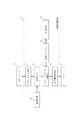
図1は、第1の実施形態に係る画像処理装置の構成を示すブロック図であり、画像を表示するカラーモニタ10と画像を記録媒体上に印刷するプリンタ17が、画像処理装置18に接続されている様子を示している。画像処理装置18の構成要素として、ビデオ信号生成部11は、画像データをビデオ信号に変換する。メモリ12は、画像データを格納する。画像データは、例えば、画像処理装置18に接続されるハードディスク等の記憶装置19に記憶されており、記憶装置19より入力される。色補正テーブル13は、モニタ表示と印刷の色の対応が記憶される。カラーマッチング処理部14は、色補正テーブル13を参照してモニタ表示と印刷の色のマッチングを行う。平滑化部15は、色補正テーブル13に格納されたデータの平滑化を行う。出力画像処理部16は、画像データをプリンタ駆動信号に変換する。
【0021】
本実施形態において、処理対象となる画像データは、デジタルカメラ、スキャナ等の画像入力装置によってデジタル化されたデータや、コンピュータグラフィックス(CG)として生成されたデータであり、明るさに対応した画素値として画像メモリ12に予め格納されているものとする。具体的に各画素値は、レッド(R)、グリーン(G)、ブルー(B)の8ビット値を有するものとする。
【0022】
本実施形態において、カラーモニタ10は、CRTまたはLCDなどの表示装置である。また、プリンタ17は、インクジェット方式によるもので、出力用紙上にシアン(C)、マゼンタ(M)、イエロー(Y)、ブラック(K)のインク滴を吐出定着させ、その密度により色の濃淡を表現する。なお、カラーモニタ10及びプリンタ17としてはこのような形態に限定されず、例えば、プリンタ17、は電子写真方式や熱転写方式等、他の方式によるものであっても良い。
【0023】
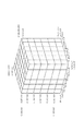
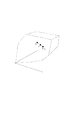
また、本実施形態において、色補正テーブル13は、入力RGB値に対してプリンタ17の出力特性を考慮するための色補正処理を行うテーブルであり、RGB色空間において規則的に配置された格子点の色座標データと、前記色補正処理後の色座標データとの対応が格納されたものである。前記RGB色空間での色補正処理前の格子点を模式図を図2に示す。図2では、R軸、G軸、B軸ともに格子点数を7と取っており、ブラック(Bk)、グリーン(G)、レッド(R)、シアン(C)、マゼンタ(M)、ホワイト(W)にあたる各標本点のRGB値、ならびにグリッド番号による標本点のグリッド座標とが記されている。図3は、色補正テーブル13の詳細を表す図である。同図に示すようにテーブル先頭には、R/G/B値の各ステップが示され、続いて色補正データが格納されている。色補正テーブル13による色補正処理後の前記格子点の模式図を図4に示す。図4では、ブラック(Bk)、グリーン(G)、レッド(R)、シアン(C)、マゼンタ(M)、ホワイト(W)にあたる各標本点の色補正後のRGB値、ならびにグリッド番号による標本点のグリッド座標とが記されている。
【0024】
図1に示す画像処理装置において、記憶装置19より入力されて画像メモリ12に格納された画像データは、カラーマッチング処理部14に供給される。カラーマッチング処理部14においては、ビデオ信号生成部11を経てカラーモニタ10に表示される画像と、出力画像処理部16を経てプリンタ17により印刷される出力画像について、色のマッチングを行う。具体的には、画像データの各画素値に対応する出力値を、色補正テーブル13を参照して補間することにより求める。その後、出力画像処理部16において入力RGB画素値に対してCMYKの各インクの吐出を制御することにより、プリンタ17で所望の色を記録媒体上に再現する。
【0025】
以下、平滑化部15における処理について、図5のフローチャートに従って詳細に説明する。まずステップS100において、平滑化部15は、平滑化前の色補正テーブル13に格納されたRGB値を読み込む。次にステップS101において、平滑化部15は、読み込まれたRGB値に対して、RGB色空間上における平滑化処理を行う。前記平滑化処理は、RGB各軸方向に隣接するRGB値の平均をとっても良いし、ガウシアン等のフィルタを用いて行っても良い。続いてステップS102において、平滑化前のRGB値が無彩色、すなわちRGB値の関係がR=G=Bであるかチェックし、平滑化前のRGB値が無彩色であると判断されれば、ステップS103に進む。ステップS103では、無彩色のRGB値が、平滑化によって無彩色軸からずれてしまったRGB値を再び無彩色軸上の値となるよう修正する。
【0026】
図6は、ステップS103を説明する図であり、601は無彩色軸、602はステップS101の平滑化処理によって無彩色軸601からずれた点、603は修正後の点である。前記無彩色軸601からずれた点602のRGB値を(r,g,b)、修正後の点603の値を(r’,g’,b’)としたとき、(r’,g’,b’)は以下の式により求められる。
r’=g’=b’=(r+g+b)/3
図5に戻り、ステップS104では、平滑化後のRGB値を色補正テーブル13に格納する。その後ステップS105に進み、色補正テーブル13の要素全てについて処理が終了していれば平滑化部15における処理を終了する。処理が終了していなければ、次のRGB値に対してステップS100からS104までを繰り返す。
【0027】
上述の方法により、無彩色である点のRGB値は、無彩色を保ちつつグレー軸上の点の値にも平滑化による周囲の色の影響を反映させることができる。このためグレー軸を挟んだ色のグラデーション画像における擬似輪郭を低減することが可能となる。
【0028】
<第2実施形態>
本発明の第2実施形態は、上述の第1実施形態の機能に加えて、平滑化による値の変動に対する制限値をユーザが設定できることを特徴とする。なお、第2実施形態の画像処理装置の構成は、上述した第1実施形態における画像処理装置18と同様である。
【0029】
図7は、本実施形態における平滑化部15の構成を示すブロック図である。同図において、変化量制限値指定部20は、色補正テーブル13に格納されたRGB値に対し、平滑化処理によって移動する際の変動量の制限値が、入力部24からのユーザ入力によって設定される。仮平滑化部21は、フィルタ処理等により色補正テーブル13に格納されたRGB値の平滑化を行う。変化量演算部22は、仮平滑化部21において平滑化されたRGB値と平滑化前のRGB値の色差ΔEを算出する。修正部23は、変化量演算部22において求められたΔEに基づき仮平滑化部21において求められたRGB値を修正し、色補正テーブル13に格納する。
【0030】
図8は、変化量制限値指定部20における表示画面の一例である。ユーザは、この表示画面とキーボード等の入力部24を用いて、平滑化前と平滑化後のRGB値の変化量制限値を、色差ΔEを用いて指定する。例えば、本図においては、平滑化前後の色差ΔEが1.5以内に制限するよう指定されていることを示す。
【0031】
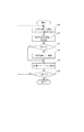
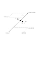
以下、本実施形態における平滑化部15の処理について、図9のフローチャートを参照して詳細に説明する。まずステップS901において、変化量制限値指定部20で上述した変化量制限値を指定する。次にステップS902で仮平滑化部21において、色補正テーブル13に格納された各値について、第1実施形態におけるステップS100〜S105と同様の方法によって平滑化処理(以後仮平滑化と呼ぶ)を行う。続いてステップS903で、変化量演算部22はステップS902にて求められた仮平滑化後のRGB値と、仮平滑化処理前のRGB値の色差ΔEを算出する。平滑化前後のRGB値に対応するΔEは、以下のようにして算出される。まずコンピュータシステム上で、RGB色空間上において規則的に配置された格子点の色座標データを色パッチとして平滑化前後のパッチ画像をそれぞれ作成して、プリンタ17により出力し、出力されたパッチ画像をそれぞれ測色して各パッチに対応するL*a*b*値を得る。この測色結果を基に、平滑化前並びに平滑化後の色補正テーブル13に対応するL*a*b*値を補間により求め、この2つのL*a*b*値から色差ΔEを算出する。平滑化前後のRGB値に対応するΔEは、或いはCIECAM97sに定められた知覚順応を考慮したRGB−Lab変換計算を用いて求められる。ステップS904では、修正部23はステップS903にて算出された色差ΔEを、前記変化量制限値と比較し、前記ΔEが制限値より大きければステップS905に進み、それ以外の場合はステップS906へ進む。ステップS905では、修正部23は前記色差ΔEが前記変化量制限値以下となるよう仮平滑化後のRGB値を修正する。図10に、RGB色空間において、平滑化前の色(RGB値)P0、仮平滑化後の色Ptemp、修正後の色P’の関係を示す。修正部23は図10に示すように、修正後の色P’が平滑化前の色P0と仮平滑化後の色Ptempを端点とするライン上に位置するよう、前記修正処理を行う。続いて修正部23は、ステップS906において該修正済みRGB値を色補正テーブル13に格納する。ステップS907において、補正テーブル13の全ての値について平滑化処理が終了したか確認し、終了していなければ、色補正テーブル13中の次の値に対してステップS901〜S906の処理を繰り返す。終了していれば、色補正テーブル13の平滑化処理を終了する。
【0032】
なお、上記変化量制限値を無彩色とそれ以外の色について、別々に制限値を設定することも可能である。図11は、無彩色とそれ以外の色について別々に制限値を設けた場合の変化量制限値指定部20における表示画面の一例である。図11において、110は無彩色以外の色に対する前記変化量制限値を設定する項目である。111は無彩色に対する前記変化量制限値を設定する項目であり、無彩色軸上の任意の格子点について変化量制限値を設定することができる。変化量制限値を設定された格子点間に位置する他の格子点については、補間により変化量制限値を算出し、図11に示すようなグラフとして表示する。補間方法は、線形補間でも良いし、スプライン関数等を用いた非線形補間を用いても良い。
【0033】
また、上記の説明において変化量制限値はLab色空間における距離即ち色差ΔEを用いたが、RGB色空間等、他の色空間における距離として定義することも可能である。
【0034】
上述の方法により、平滑化による値の変動に対する制限を任意に設定することが可能となる。また、無彩色軸上の値についても、平滑化によって無彩色軸からずれた場合一旦無彩色軸上に射影した後に上記修正処理を行うため、無彩色を保ちつつ値の変動を制限することができる。
【0035】
<他の実施形態>
本発明は、上述した第1及び第2実施形態に限定されるものではなく、例えば以下に示すような変形が可能である。
【0036】
上述した各実施形態においては、色補正テーブルに格納されたデータの平滑化処理をRGB色空間にて行ったが、Lab、CMY等他の色空間において行うことも可能である。
【0037】
なお、本発明は、複数の機器(例えばホストコンピュータ、インタフェイス機器、リーダ、プリンタなど)から構成されるシステムに適用しても、一つの機器からなる装置(例えば、複写機、ファクシミリ装置など)に適用しても良い。
【0038】
また、本発明の目的は、前述した実施形態の機能を実現するソフトウェアのプログラムコードを記録した記憶媒体を、システムあるいは装置に供給し、そのシステムあるいは装置のコンピュータ(またはCPUまたはMPU)が記憶媒体に格納されたプログラムコードを読み出し実行することによっても達成されることは言うまでもない。
【0039】
図12を用いて、コンピュータ120に適用した場合の一例を示す。図12において、コンピュータ120は、CPU121、ROM122、RAM123、入力I/F124、及び出力I/F125から構成される。入力I/Fは、図示しないユーザ入力装置に接続される。ここで、ユーザ入力装置は、図7で示した入力部24であっても良い。また、出力I/Fは、図示しない表示部やプリンタに接続される。ここで、表示部は、図8や図11で示した表示画面を表示しても良い。コンピュータ120において、図5や図9において示した、上記各実施形態における平滑化を制御するプログラムは、記憶媒体としてROM122に記憶され、CPU121によって実行される。
【0040】
この場合、記憶媒体から読み出されたプログラムコード自体が前述した実施形態の機能を実現することになり、そのプログラムコードを記憶した記憶媒体は本発明を構成することになる。
【0041】
上記した他にプログラムコードを供給するための記憶媒体としては、例えば、フロッピー(R)ディスク、ハードディスク、光ディスク、光磁気ディスク、CD−ROM、CD−R、磁気テープ、不揮発性のメモリカードなどを用いることが出来る。
【0042】
さらに、記憶媒体から読み出されたプログラムコードが、コンピュータに挿入された機能拡張ボードやコンピュータに接続された機能拡張ユニットに備わるメモリに書き込まれた後、そのプログラムコードの指示に基づき、その機能拡張ボードや機能拡張ユニットに備わるCPUなどが実際の処理の一部または全部を行い、その処理によって前述した実施形態の機能が実現される場合も含まれることは言うまでもない。
【0043】
さらに、記憶媒体から読み出されたプログラムコードが、コンピュータに挿入された機能拡張ボードやコンピュータに接続された機能拡張ユニットに備わるメモリに書き込まれた後、そのプログラムコードの指示に基づき、その機能拡張ボードや機能拡張ユニットに備わるCPUなどが実際の処理の一部または全部を行い、その処理によって前述した実施形態の機能が実現される場合も含まれることはいうまでもない。
【0044】
【発明の効果】
以上説明したように、本発明によれば、無彩色を保ちつつグレー軸上の値にも平滑化による周囲の色の影響を反映させることができる。このためグレー軸を挟んだ色のグラデーション画像における擬似輪郭の低減、及びグレー近辺のノイズの抑制が可能となり、画質をより向上することができる。
【図面の簡単な説明】
【図1】実施の形態に係る色調整装置を適用した画像処理装置の構成を示すブロック図である。
【図2】RGB色空間での色補正処理前の格子点配置を表す模式図である。
【図3】色補正テーブルに保持されるデータ列を示す図である。
【図4】RGB色空間での色補正処理後の格子点配置を表す模式図である。
【図5】平滑化処理を示すフローチャートである。
【図6】平滑化によって無彩色軸からずれたグレーを再び無彩色軸上となるよう修正する処理を説明する図である。
【図7】一実施形態にかかる色調整装置の構成を示すブロック図である。
【図8】平滑化による変動量に対する制限値を指定する表示画面の例を示す図である。
【図9】第2実施形態における平滑化処理を示すフローチャートである。
【図10】RGB空間上における平滑化処理前、仮平滑化後、平滑化処理後の色の関係を示す図である。
【図11】平滑化による変動量に対する制限値を指定する表示画面の例を示す図である。
【図12】実施形態に関わるコンピュータの構成を示すブロック図である。[0001]
TECHNICAL FIELD OF THE INVENTION
The present invention relates to a color correction table creation method, a control program, a storage medium, and an apparatus.
[0002]
[Prior art]
Generally, when an image displayed on a monitor is printed out from a printer in a computer system or the like, the color gamut of the monitor and that of the printer are greatly different, so that the colors of the monitor display color and the print color are substantially equal. In other words, a so-called color matching process for adjusting the image quality is required. As a color matching process, for example, a color correction method of performing an interpolation operation by referring to a color correction look-up table (hereinafter, a color correction table) in consideration of color characteristics of a monitor and a printer is known.
[0003]
However, in the process of creating the color correction table, various noises may be generated and mixed into the values of the created color correction table. For example, color measurement is generally performed in order to know the actual characteristics of a printer, and a measurement error at the time of the color measurement may cause the noise. Another cause of noise generation is a quantization error when quantizing the calculation processing result. If the noise generated for the above-mentioned reason is mixed in the color correction table, the change in the value of the table will not be smooth. As a result, the gradation change is not smooth in the image after the color correction, and when the image is printed by a printer, a problem such as a false contour easily occurs.
[0004]
Therefore, in order to remove noise in the color correction table, for example, Japanese Patent Application No. 2001-308643 performed a smoothing process on the values in the color correction table. At this time, the color correction table corresponding to the achromatic color (R = G = B) of the input image data is kept achromatic, so that the input image data value is fixed.
[0005]
[Problems to be solved by the invention]
However, when the achromatic color is fixed as in the above-described conventional technology, only the achromatic color is not affected by the fluctuation due to the smoothing of the peripheral colors, so that the gradation changes smoothly particularly in the gradation image of the complementary color sandwiching the achromatic color. In some cases, false contours were generated.
[0006]
The present invention has been made to solve the above problem, and suppresses false contours by reflecting a change in a nearby color due to smoothing in an achromatic color while maintaining an achromatic color (gray balance). An object of the present invention is to further improve image quality by suppressing noise near coloring.
[0007]
[Means for Solving the Problems]
As one means for achieving the above object, a color correction table creating method of the present invention has the following configuration.
[0008]
In a color correction table creating method for creating a color correction table by performing smoothing on a plurality of color values on a color space, the smoothing is performed on achromatic color values on the color space. When the value of the achromatic color is converted into a second value that is not an achromatic color, the second value is corrected.
[0009]
Further, in the above method, it is characterized in that the second value is corrected to be changed to a value on an achromatic color axis.
[0010]
In the above method, the second value is corrected so as to be projected on the achromatic color axis in the color space.
[0011]
Further, in the above method, a smoothing condition in the smoothing is set.
[0012]
Further, in the above method, the smoothing condition is a limit value of a color change amount before and after the smoothing.
[0013]
In the above method, the smoothing condition is set to an achromatic color and a non-achromatic color, respectively.
[0014]
Further, in the above method, the smoothing condition for the achromatic color is based on a limit value of a color change amount at a plurality of positions on an achromatic color axis.
[0015]
The control program of the present invention realizes the color correction table creating method by a computer.
[0016]
The storage medium of the present invention stores the control program.
[0017]
Further, the color correction table creating device of the present invention has the following configuration.
[0018]
In a color correction table creating apparatus for creating a color correction table by performing smoothing on a plurality of color values in a color space, a smoothing unit for smoothing an achromatic color value in the color space A correction unit that corrects the second value when the value of the achromatic color is converted to a second value that is not achromatic by the smoothing.
[0019]
BEST MODE FOR CARRYING OUT THE INVENTION
Hereinafter, embodiments of the present invention will be described in detail with reference to the drawings.
[0020]
<First embodiment>
FIG. 1 is a block diagram showing a configuration of an image processing apparatus according to the first embodiment. A
[0021]
In the present embodiment, the image data to be processed is data digitized by an image input device such as a digital camera or a scanner, or data generated as computer graphics (CG). It is assumed that the value is stored in the
[0022]
In the present embodiment, the
[0023]
In the present embodiment, the color correction table 13 is a table for performing a color correction process for considering the output characteristics of the
[0024]
In the image processing device shown in FIG. 1, image data input from the
[0025]
Hereinafter, the processing in the smoothing
[0026]
FIG. 6 is a diagram for explaining step S103, in which 601 is an achromatic axis, 602 is a point shifted from the
r ′ = g ′ = b ′ = (r + g + b) / 3
Returning to FIG. 5, in step S104, the RGB values after smoothing are stored in the color correction table 13. Thereafter, the process proceeds to step S105, and if the processing has been completed for all the elements of the color correction table 13, the processing in the smoothing
[0027]
According to the above-described method, the RGB values of the achromatic point can reflect the influence of the surrounding colors due to the smoothing on the value of the point on the gray axis while maintaining the achromatic color. For this reason, it is possible to reduce the pseudo contour in the gradation image of the color sandwiching the gray axis.
[0028]
<Second embodiment>
The second embodiment of the present invention is characterized in that, in addition to the functions of the above-described first embodiment, a user can set a limit value for a change in value due to smoothing. The configuration of the image processing apparatus according to the second embodiment is the same as that of the
[0029]
FIG. 7 is a block diagram illustrating a configuration of the smoothing
[0030]
FIG. 8 is an example of a display screen of the change amount limit value specifying unit 20. Using this display screen and the
[0031]
Hereinafter, the processing of the smoothing
[0032]
It should be noted that the change amount limit value can be set separately for achromatic colors and other colors. FIG. 11 is an example of a display screen in the change amount limit value specifying unit 20 when limit values are separately set for achromatic colors and other colors. In FIG. 11,
[0033]
In the above description, the change amount limit value uses the distance in the Lab color space, that is, the color difference ΔE, but may be defined as the distance in another color space such as the RGB color space.
[0034]
According to the above-described method, it is possible to arbitrarily set a limit on a value change due to smoothing. Also, for values on the achromatic axis, if the values are shifted from the achromatic axis due to smoothing, the above correction processing is performed after projecting onto the achromatic axis once. it can.
[0035]
<Other embodiments>
The present invention is not limited to the above-described first and second embodiments, and for example, the following modifications are possible.
[0036]
In each of the embodiments described above, the data stored in the color correction table is smoothed in the RGB color space, but may be performed in another color space such as Lab or CMY.
[0037]
The present invention can be applied to a system including a plurality of devices (for example, a host computer, an interface device, a reader, a printer, etc.), but may be a device including one device (for example, a copying machine, a facsimile machine, etc.). May be applied.
[0038]
Further, an object of the present invention is to provide a storage medium storing a program code of software for realizing the functions of the above-described embodiments to a system or an apparatus, and a computer (or CPU or MPU) of the system or apparatus to store the storage medium. Needless to say, this can also be achieved by reading out and executing the program code stored in the.
[0039]
An example in which the present invention is applied to the
[0040]
In this case, the program code itself read from the storage medium realizes the function of the above-described embodiment, and the storage medium storing the program code constitutes the present invention.
[0041]
Other storage media for supplying the program code include, for example, a floppy (R) disk, hard disk, optical disk, magneto-optical disk, CD-ROM, CD-R, magnetic tape, and non-volatile memory card. Can be used.
[0042]
Further, after the program code read from the storage medium is written into a memory provided on a function expansion board inserted into the computer or a function expansion unit connected to the computer, the function expansion is performed based on the instruction of the program code. It goes without saying that a CPU or the like provided in the board or the function expansion unit performs part or all of the actual processing, and the processing realizes the functions of the above-described embodiments.
[0043]
Further, after the program code read from the storage medium is written into a memory provided on a function expansion board inserted into the computer or a function expansion unit connected to the computer, the function expansion is performed based on the instruction of the program code. It goes without saying that a CPU or the like provided in the board or the function expansion unit performs part or all of the actual processing, and the processing realizes the functions of the above-described embodiments.
[0044]
【The invention's effect】
As described above, according to the present invention, it is possible to reflect the influence of the surrounding colors due to the smoothing on the values on the gray axis while maintaining the achromatic color. For this reason, it is possible to reduce the pseudo contour in the gradation image of the color sandwiching the gray axis and to suppress the noise near gray, so that the image quality can be further improved.
[Brief description of the drawings]
FIG. 1 is a block diagram illustrating a configuration of an image processing device to which a color adjustment device according to an embodiment is applied.
FIG. 2 is a schematic diagram illustrating a grid point arrangement before a color correction process in an RGB color space.
FIG. 3 is a diagram showing a data string held in a color correction table.
FIG. 4 is a schematic diagram illustrating a grid point arrangement after a color correction process in an RGB color space.
FIG. 5 is a flowchart illustrating a smoothing process.
FIG. 6 is a diagram illustrating a process of correcting a gray shifted from an achromatic color axis by smoothing so as to be on an achromatic color axis again.
FIG. 7 is a block diagram illustrating a configuration of a color adjustment device according to one embodiment.
FIG. 8 is a diagram illustrating an example of a display screen for specifying a limit value for a fluctuation amount due to smoothing.
FIG. 9 is a flowchart illustrating a smoothing process according to the second embodiment.
FIG. 10 is a diagram illustrating a relationship between colors before, after provisional smoothing, and after smoothing processing in an RGB space.
FIG. 11 is a diagram showing an example of a display screen for specifying a limit value for a fluctuation amount due to smoothing.
FIG. 12 is a block diagram illustrating a configuration of a computer according to the embodiment.
Claims (1)
前記色空間上における無彩色の値に対して平滑化を行い、
前記平滑化により該無彩色の値が無彩色でない第2の値へ変換された場合該第2の値を補正する、
ことを特徴とする色補正テーブル作成方法。In a color correction table creating method for creating a color correction table by performing smoothing on a plurality of color values in a color space,
Performs smoothing on achromatic color values on the color space,
Correcting the second value when the value of the achromatic color is converted to a second value that is not an achromatic color by the smoothing;
A color correction table creating method, characterized in that:
Priority Applications (2)
| Application Number | Priority Date | Filing Date | Title |
|---|---|---|---|
| JP2002286048A JP2004128585A (en) | 2002-09-30 | 2002-09-30 | Color correction table forming method, control program, storing medium, and apparatus thereof |
| US10/664,204 US7427992B2 (en) | 2002-09-30 | 2003-09-16 | Color correction table compiling method, controlling program, recording medium, and device |
Applications Claiming Priority (1)
| Application Number | Priority Date | Filing Date | Title |
|---|---|---|---|
| JP2002286048A JP2004128585A (en) | 2002-09-30 | 2002-09-30 | Color correction table forming method, control program, storing medium, and apparatus thereof |
Publications (2)
| Publication Number | Publication Date |
|---|---|
| JP2004128585A true JP2004128585A (en) | 2004-04-22 |
| JP2004128585A5 JP2004128585A5 (en) | 2005-10-13 |
Family
ID=32211534
Family Applications (1)
| Application Number | Title | Priority Date | Filing Date |
|---|---|---|---|
| JP2002286048A Pending JP2004128585A (en) | 2002-09-30 | 2002-09-30 | Color correction table forming method, control program, storing medium, and apparatus thereof |
Country Status (2)
| Country | Link |
|---|---|
| US (1) | US7427992B2 (en) |
| JP (1) | JP2004128585A (en) |
Families Citing this family (6)
| Publication number | Priority date | Publication date | Assignee | Title |
|---|---|---|---|---|
| KR20050080393A (en) * | 2004-02-09 | 2005-08-12 | 삼성전자주식회사 | Video controll device using color coordinate and method thereof |
| JP2006013836A (en) * | 2004-06-25 | 2006-01-12 | Seiko Epson Corp | Image data processing for processing color image data of color image |
| JP6639138B2 (en) * | 2015-07-30 | 2020-02-05 | キヤノン株式会社 | Image processing apparatus, image processing method, and program |
| JP6804022B2 (en) * | 2016-05-02 | 2020-12-23 | 富士ゼロックス株式会社 | Change degree derivation device, change degree derivation method and program |
| JP6768343B2 (en) * | 2016-05-06 | 2020-10-14 | キヤノン株式会社 | Image processing equipment, image processing methods and programs |
| WO2018147861A1 (en) * | 2017-02-10 | 2018-08-16 | Hewlett-Packard Development Company, L.P. | Color calibration |
Family Cites Families (13)
| Publication number | Priority date | Publication date | Assignee | Title |
|---|---|---|---|---|
| US4929978A (en) * | 1987-10-23 | 1990-05-29 | Matsushita Electric Industrial Co., Ltd. | Color correction method for color copier utilizing correction table derived from printed color samples |
| US5357353A (en) * | 1991-05-17 | 1994-10-18 | Minolta Camera Kabushiki Kaisha | Image forming apparatus |
| EP0674430A1 (en) * | 1994-03-24 | 1995-09-27 | Eastman Kodak Company | Method and apparatus for interactive color transformation of color values between color spaces |
| US5781206A (en) * | 1995-05-01 | 1998-07-14 | Minnesota Mining And Manufacturing Company | Apparatus and method for recalibrating a multi-color imaging system |
| JP3714701B2 (en) * | 1995-06-22 | 2005-11-09 | 富士写真フイルム株式会社 | Color conversion method |
| JPH09275508A (en) * | 1996-04-08 | 1997-10-21 | Mita Ind Co Ltd | Color image generating device and method for generating its correction table |
| US6724507B1 (en) * | 1998-07-02 | 2004-04-20 | Fuji Xerox Co., Ltd. | Image processing method and image processing apparatus |
| JP2001016476A (en) | 1999-07-01 | 2001-01-19 | Canon Inc | Device and method for processing image and computer readable memory |
| JP4218165B2 (en) * | 2000-01-19 | 2009-02-04 | ブラザー工業株式会社 | Image data conversion processing method and recording medium recording image data conversion processing program |
| US7009734B2 (en) * | 2000-08-22 | 2006-03-07 | Canon Kabushiki Kaisha | Method and apparatus for forming color transform lookup table, and image processing method |
| US20020136302A1 (en) * | 2001-03-21 | 2002-09-26 | Naiqian Lu | Cascade window searching method and apparatus |
| JP4109946B2 (en) | 2001-10-04 | 2008-07-02 | キヤノン株式会社 | Color correction table creation method and apparatus, control program, and recording medium |
| US7136523B2 (en) | 2001-10-04 | 2006-11-14 | Canon Kabushiki Kaisha | Color correction table forming method and apparatus, control program and storage medium |
-
2002
- 2002-09-30 JP JP2002286048A patent/JP2004128585A/en active Pending
-
2003
- 2003-09-16 US US10/664,204 patent/US7427992B2/en not_active Expired - Fee Related
Also Published As
| Publication number | Publication date |
|---|---|
| US20040091148A1 (en) | 2004-05-13 |
| US7427992B2 (en) | 2008-09-23 |
Similar Documents
| Publication | Publication Date | Title |
|---|---|---|
| US7760398B2 (en) | Color conversion table generation method and color conversion table generation device | |
| JP4623630B2 (en) | Image processing apparatus, image processing method, program, image forming apparatus, and image forming system | |
| JP4200365B2 (en) | Correspondence definition data creation grid point determination method, correspondence definition data creation grid point determination apparatus, correspondence definition data creation grid point determination program, print control apparatus, print control method, print control program, and image data processing apparatus | |
| US8204304B2 (en) | Color gamut mapping by forming curved cross-sectional surfaces | |
| JP2002359748A (en) | Medium for recording color transformation program, color transformation program, method for generating color transformation table, medium for recording color transformation table data, color transformation device, color transformation method and color transformation table | |
| JP2008154008A (en) | Method and device for generating gradation correction table | |
| JP2005253072A5 (en) | ||
| US20040126009A1 (en) | Image processing apparatus, image processing method, and image processing program | |
| JP2009010889A (en) | Image processor and profile creation method | |
| JP2004320625A (en) | Lattice point determining method for preparing correspondence relation defining data, lattice point determining apparatus for preparing correspondence relation defining data, lattice point determining program for preparing correspondence relation defining data, print control apparatus, print control method, and print control program | |
| JP2006262238A (en) | Image processing method, image processor and image processing program | |
| US6995881B2 (en) | Image processing method and program capable of reducing graininess | |
| JP2003338938A (en) | Method, apparatus and program for image processing | |
| JP2007088636A (en) | Color separation table generating method and image processing apparatus | |
| JP2008160475A (en) | Image output method and image output apparatus | |
| JP2004128585A (en) | Color correction table forming method, control program, storing medium, and apparatus thereof | |
| JP4109946B2 (en) | Color correction table creation method and apparatus, control program, and recording medium | |
| JP2000190572A (en) | Method for processing image and print system | |
| JP4420447B2 (en) | Color processing apparatus and color processing method | |
| JPH089179A (en) | Image processing unit and its method | |
| JP2003334934A (en) | Device and method for controlling forming of image, and image forming control program | |
| JP4227371B2 (en) | Image processing apparatus and method | |
| JP2005210225A (en) | Image processor and image processing method | |
| JP5777322B2 (en) | Color processing apparatus and color processing method | |
| JP2005012286A (en) | Image forming apparatus and color tone adjustment method |
Legal Events
| Date | Code | Title | Description |
|---|---|---|---|
| A521 | Request for written amendment filed |
Free format text: JAPANESE INTERMEDIATE CODE: A523 Effective date: 20050610 |
|
| A621 | Written request for application examination |
Free format text: JAPANESE INTERMEDIATE CODE: A621 Effective date: 20050610 |
|
| A977 | Report on retrieval |
Free format text: JAPANESE INTERMEDIATE CODE: A971007 Effective date: 20061227 |
|
| A131 | Notification of reasons for refusal |
Free format text: JAPANESE INTERMEDIATE CODE: A131 Effective date: 20070109 |
|
| A02 | Decision of refusal |
Free format text: JAPANESE INTERMEDIATE CODE: A02 Effective date: 20070626 |