JP5565183B2 - Film production method - Google Patents
Film production method Download PDFInfo
- Publication number
- JP5565183B2 JP5565183B2 JP2010177107A JP2010177107A JP5565183B2 JP 5565183 B2 JP5565183 B2 JP 5565183B2 JP 2010177107 A JP2010177107 A JP 2010177107A JP 2010177107 A JP2010177107 A JP 2010177107A JP 5565183 B2 JP5565183 B2 JP 5565183B2
- Authority
- JP
- Japan
- Prior art keywords
- film
- control command
- block
- die
- time
- Prior art date
- Legal status (The legal status is an assumption and is not a legal conclusion. Google has not performed a legal analysis and makes no representation as to the accuracy of the status listed.)
- Expired - Fee Related
Links
Images


Classifications
-
- B—PERFORMING OPERATIONS; TRANSPORTING
- B29—WORKING OF PLASTICS; WORKING OF SUBSTANCES IN A PLASTIC STATE IN GENERAL
- B29C—SHAPING OR JOINING OF PLASTICS; SHAPING OF MATERIAL IN A PLASTIC STATE, NOT OTHERWISE PROVIDED FOR; AFTER-TREATMENT OF THE SHAPED PRODUCTS, e.g. REPAIRING
- B29C48/00—Extrusion moulding, i.e. expressing the moulding material through a die or nozzle which imparts the desired form; Apparatus therefor
- B29C48/25—Component parts, details or accessories; Auxiliary operations
- B29C48/30—Extrusion nozzles or dies
- B29C48/305—Extrusion nozzles or dies having a wide opening, e.g. for forming sheets
- B29C48/31—Extrusion nozzles or dies having a wide opening, e.g. for forming sheets being adjustable, i.e. having adjustable exit sections
- B29C48/313—Extrusion nozzles or dies having a wide opening, e.g. for forming sheets being adjustable, i.e. having adjustable exit sections by positioning the die lips
-
- B—PERFORMING OPERATIONS; TRANSPORTING
- B29—WORKING OF PLASTICS; WORKING OF SUBSTANCES IN A PLASTIC STATE IN GENERAL
- B29C—SHAPING OR JOINING OF PLASTICS; SHAPING OF MATERIAL IN A PLASTIC STATE, NOT OTHERWISE PROVIDED FOR; AFTER-TREATMENT OF THE SHAPED PRODUCTS, e.g. REPAIRING
- B29C48/00—Extrusion moulding, i.e. expressing the moulding material through a die or nozzle which imparts the desired form; Apparatus therefor
- B29C48/03—Extrusion moulding, i.e. expressing the moulding material through a die or nozzle which imparts the desired form; Apparatus therefor characterised by the shape of the extruded material at extrusion
- B29C48/07—Flat, e.g. panels
- B29C48/08—Flat, e.g. panels flexible, e.g. films
-
- B—PERFORMING OPERATIONS; TRANSPORTING
- B29—WORKING OF PLASTICS; WORKING OF SUBSTANCES IN A PLASTIC STATE IN GENERAL
- B29C—SHAPING OR JOINING OF PLASTICS; SHAPING OF MATERIAL IN A PLASTIC STATE, NOT OTHERWISE PROVIDED FOR; AFTER-TREATMENT OF THE SHAPED PRODUCTS, e.g. REPAIRING
- B29C48/00—Extrusion moulding, i.e. expressing the moulding material through a die or nozzle which imparts the desired form; Apparatus therefor
- B29C48/25—Component parts, details or accessories; Auxiliary operations
- B29C48/92—Measuring, controlling or regulating
-
- B—PERFORMING OPERATIONS; TRANSPORTING
- B29—WORKING OF PLASTICS; WORKING OF SUBSTANCES IN A PLASTIC STATE IN GENERAL
- B29C—SHAPING OR JOINING OF PLASTICS; SHAPING OF MATERIAL IN A PLASTIC STATE, NOT OTHERWISE PROVIDED FOR; AFTER-TREATMENT OF THE SHAPED PRODUCTS, e.g. REPAIRING
- B29C2948/00—Indexing scheme relating to extrusion moulding
- B29C2948/92—Measuring, controlling or regulating
- B29C2948/92504—Controlled parameter
- B29C2948/92561—Time, e.g. start, termination, duration or interruption
-
- B—PERFORMING OPERATIONS; TRANSPORTING
- B29—WORKING OF PLASTICS; WORKING OF SUBSTANCES IN A PLASTIC STATE IN GENERAL
- B29C—SHAPING OR JOINING OF PLASTICS; SHAPING OF MATERIAL IN A PLASTIC STATE, NOT OTHERWISE PROVIDED FOR; AFTER-TREATMENT OF THE SHAPED PRODUCTS, e.g. REPAIRING
- B29C2948/00—Indexing scheme relating to extrusion moulding
- B29C2948/92—Measuring, controlling or regulating
- B29C2948/92504—Controlled parameter
- B29C2948/92609—Dimensions
- B29C2948/92647—Thickness
-
- B—PERFORMING OPERATIONS; TRANSPORTING
- B29—WORKING OF PLASTICS; WORKING OF SUBSTANCES IN A PLASTIC STATE IN GENERAL
- B29C—SHAPING OR JOINING OF PLASTICS; SHAPING OF MATERIAL IN A PLASTIC STATE, NOT OTHERWISE PROVIDED FOR; AFTER-TREATMENT OF THE SHAPED PRODUCTS, e.g. REPAIRING
- B29C2948/00—Indexing scheme relating to extrusion moulding
- B29C2948/92—Measuring, controlling or regulating
- B29C2948/92819—Location or phase of control
- B29C2948/92857—Extrusion unit
- B29C2948/92904—Die; Nozzle zone
Description
本発明は、厚みムラの小さいフィルム、より詳細には長尺状に製造され、特にロールに巻き取られるフィルムの製造方法に関する。 The present invention relates to a method for producing a film having a small thickness unevenness, more specifically, a film that is produced in a long shape and is wound around a roll.
ポリイミドフィルムの製造する方法としては、
(1)ポリアミック酸溶液、またはポリアミック酸溶液に必要に応じてイミド化触媒、有機リン含有化合物、無機微粒子などを選択して加えたポリアミック酸溶液組成物をフィルム状に支持体上に流延し、加熱乾燥して自己支持性フィルムを得た後、熱的に脱水環化、脱溶媒させてポリイミドフィルムを得る方法、および
(2)ポリアミック酸溶液に環化触媒及び脱水剤を加え、さらに必要に応じて無機微粒子などを選択して加えたポリアミック酸溶液組成物をフィルム状に支持体上に流延し、化学的に脱水環化させて、必要に応じて加熱乾燥して自己支持性フィルムを得た後、これを加熱脱溶媒、イミド化することによりポリイミドフィルムを得る方法
が知られている。
As a method of manufacturing a polyimide film,
(1) A polyamic acid solution or a polyamic acid solution composition in which an imidization catalyst, an organic phosphorus-containing compound, inorganic fine particles, etc. are selected and added to a polyamic acid solution as necessary is cast on a support in the form of a film. , After drying by heating to obtain a self-supporting film, thermally dehydrating cyclization, removing solvent to obtain a polyimide film, and (2) adding a cyclization catalyst and a dehydrating agent to the polyamic acid solution, and further required A polyamic acid solution composition selected by adding inorganic fine particles depending on the condition is cast on a support, chemically dehydrated and cyclized, and heated and dried as necessary to form a self-supporting film. After obtaining the above, there is known a method of obtaining a polyimide film by heating to remove the solvent and imidization.
どちらの製造方法でも、ポリアミック酸溶液組成物を支持体上に流延するプロセスにおいては、一般に、リップ間隔の調整可能なダイスより、ポリアミック酸溶液組成物を、ベルトまたはドラム等の支持体上に流延する。流延された溶液状フィルムは、上述の各ステップにより、イミド化され、最終的に製造されたポリイミドフィルムは、一般に、ロール状に巻かれて出荷される。 In either production method, in the process of casting a polyamic acid solution composition on a support, the polyamic acid solution composition is generally applied on a support such as a belt or a drum by a die having an adjustable lip interval. Cast. The cast solution-like film is imidized by the above-described steps, and the finally produced polyimide film is generally wound into a roll and shipped.
ポリイミドフィルムは、表面に銅などの金属配線を形成した配線基板として使用され、さらに配線基板にICチップなどのチップを搭載して使用される。そのため、ポリイミドフィルムは幅方向や長さ方向に優れた厚みの均一性が要求される。 The polyimide film is used as a wiring board having a metal wiring such as copper formed on the surface, and is further used by mounting a chip such as an IC chip on the wiring board. Therefore, the polyimide film is required to have excellent thickness uniformity in the width direction and the length direction.
厚みの均一なポリイミドフィルムを連続して得る方法として、例えば特許文献1では、ポリイミドの前駆体であるポリアミド酸の溶液を、走行する支持体上に塗布し、塗布された塗膜を乾燥して自己支持性のフィルムとなし、自己支持性のフィルムを支持体から剥離してさらに熱処理してポリイミドフィルムを得る製膜方法において、乾燥時の支持体の走行する方向に直交する幅方向の支持体上の温度を中心値±5℃以内に制御することを特徴とするポリイミドフィルム製膜方法が開示されている。特許文献2では、ポリアミド酸化合物を口金からシート状に押出し、化学閉環または熱閉環させることによりゲル状のフィルムを得、これを乾燥して得たポリイミドフィルムの幅方向の厚みムラを製造工程上で連続測定し、このデータをフィードバックすることにより、フィルム幅方向(TD)の厚みムラが3.0%以下で、かつフィルム長手方向(MD)におよそ10mおきに測定したTD厚みを積層し、平均化することによって得られるTD厚みプロファイルの最大厚みと最小厚みの差が、フィルム平均厚みの2.0%以下となるように口金の間隙を調整し、さらにフィルムのTD延伸倍率を調整することにより、TDのヤング率が340kg/mm2以上、TDの5%延伸強度(F−50)が10kg/mm2以上、さらにテンター内のTD温度プロファイルを調整することにより長手方向のフィルム長さ6.5mでの片伸びが9mm以下となるように制御を行うことを特徴とするポリイミドフィルムの製造方法が開示されている。
As a method for continuously obtaining a polyimide film having a uniform thickness, for example, in
一方でポリイミドフィルムの製品ロールの不良として、巻こぶ、多角形化、ハイエッジが存在する。巻こぶは、フィルムの幅方向に厚い箇所があると、微細な厚みムラであっても、巻物として積層されることによりその差が顕著になり、高いこぶが生じる問題である。また、ポリイミドフィルムは剛性に優れるため、巻こぶがある状態で巻ずれが発生すると擦り傷が発生する問題もある。多角形化は、ポリイミドフィルムの製品ロールを長期間保管しておいたときに、応力緩和によってフィルムが変形し、皺が発生する問題である。この問題は、ポリイミドフィルムの製品ロール硬度が不均一であり、硬度の高い箇所の間隔が広い場合に発生し易い。ハイエッジは、フィルムをカットした際、端部に盛り上がった部分が発生する問題であり、スリット刃の切れ不良やポリイミドフィルムの局所的に厚い箇所をカットした際に発生し易い。いずれの問題もポリイミドフィルムの幅方向に厚い箇所が存在すると発生し易くなるため、厚みムラを極力小さくする必要がある。 On the other hand, there are winding edges, polygonalization, and high edges as defective product rolls of polyimide film. If there is a thick part in the width direction of the film, even if the thickness unevenness is minute, the difference becomes remarkable by being laminated as a scroll, and a high hump is caused. In addition, since the polyimide film is excellent in rigidity, there is a problem that scratches occur when winding deviation occurs in the presence of a hump. Polygonalization is a problem that when a product roll of polyimide film is stored for a long period of time, the film is deformed by stress relaxation and wrinkles are generated. This problem is likely to occur when the product roll hardness of the polyimide film is uneven and the interval between the high hardness portions is wide. The high edge is a problem that a raised portion is generated at the end when the film is cut, and is likely to occur when a slit blade is poorly cut or a locally thick portion of the polyimide film is cut. Any problem is likely to occur when there is a thick portion in the width direction of the polyimide film, and thus it is necessary to reduce the thickness unevenness as much as possible.
巻こぶの解消に関しては、Tダイから溶融押出成形されるフィルム製造において、従来、得られるフィルムの幅方向の厚みを計測し、その結果を基にしてTダイのリップ間隔を制御する方法で行われている。 In order to eliminate the hump, in the production of a film that is melt-extruded from a T-die, conventionally, the thickness of the obtained film is measured in the width direction, and the lip interval of the T-die is controlled based on the result. It has been broken.
例えば、特許文献3では、押出ダイから溶融押出されるプラスチックフィルムの巻物プロファイル制御方法として、幅方向厚さプロファイルを連続的に計測し、その厚さプロファイルを巻き上げ回数分重ね合わせる演算を行って、得られる巻物プロファイルを推定し、その巻物プロファイルに許容を超える偏差がある場合、その位置に対応する押出ダイ位置に厚さ調整操作を加える方法が記載されている。その他、特許文献4においても、厚さ計をフィルム幅方向に1回乃至複数回走査した個別プロファイル測定値をフィルム進行方向へ複数回加算平均すると共に、押出可撓リップの剛性から定まる所定バンド幅にまたがるように設定したプロファイルデータ値に基づいて、このプロファイルデータ値の最大値が予め設定した限界最大値を超える際に、最大値を減少するように、プロファイルの目標値を少なくとも所定バンド幅に亘って減少補正することで、巻こぶを発生させない制御方法が記載されている。
For example, in
また、特許文献5には、フラットダイから押し出すフィルムの厚さを、フラットダイの幅方向に複数に区分して、各区分毎に位相をずらして周期的にわずかに増減させる、巻こぶ巻ずれ防止方法が記載されている。この方法では、目標値TよりΔTだけ制御目標値が大きい区分と、目標値TよりΔTだけ厚さ制御目標値が小さい区分とが互い違いに隣接し、結果として巻取り軸心方向にわずかに波打った状態で巻き取ることにより、フィルムの巻ずれ防止と巻こぶの発生を抑制することができるとしている。
Further,
複数の位置においてリップ間隔が調整可能なTダイよりフィルム原料を連続的に支持体に押し出し、その後必要に応じて乾燥や加熱を行いフィルムを得るフィルム製造方法では、幅方向に厚みムラ、特に局所的な厚みムラを生じると、得られるフィルムの厚みプロファイルを利用した自動制御を行っても、なかなか厚みムラが解消しない。 In a film manufacturing method in which a film raw material is continuously extruded from a T-die capable of adjusting a lip interval at a plurality of positions to a support, and then dried and heated as necessary. When the thickness unevenness is generated, even if automatic control is performed using the thickness profile of the obtained film, the thickness unevenness is not easily solved.
本発明は、幅方向や長さ方向に厚みのムラのないフィルムの製造方法を提供することを目的とする。 An object of this invention is to provide the manufacturing method of a film without the thickness nonuniformity in the width direction or the length direction.
配線基板用樹脂フィルムは、表面に銅などの金属配線を形成し、その後、異方性導電接着フィルム(ACF)や金属接合(例えば、金金接合、金錫接合など)などにより、他の基板と接続したり、ICチップなどのチップ部材を搭載するなどして使用される。そのため、ポリイミドフィルムなどの配線基板用樹脂フィルムは幅方向や長さ方向に優れた厚みの均一性が要求される。本発明の態様の一つは、配線基板用樹脂フィルムと好適な幅方向や長さ方向に厚みのムラのないフィルムの製造方法を提供することを目的とする。 The resin film for wiring board forms a metal wiring such as copper on the surface, and then other substrates by anisotropic conductive adhesive film (ACF) or metal bonding (for example, gold-gold bonding, gold-tin bonding, etc.) Or a chip member such as an IC chip is mounted. Therefore, a resin film for a wiring board such as a polyimide film is required to have excellent thickness uniformity in the width direction and the length direction. One of the aspects of the present invention is to provide a resin film for a wiring board and a method for producing a film having no uneven thickness in a suitable width direction or length direction.
特に本発明の態様の一つは、ポリアミド酸溶液やポリイミド溶液を、走行する支持体上に、フィルムの厚みプロファイルを利用した自動制御機能を有する複数の位置においてリップ間隔が調整可能なTダイを用いて塗布し、塗布された塗膜を乾燥して自己支持性フィルムとなし、自己支持性フィルムを支持体から剥離してさらに加熱処理して得られる配線基板用樹脂フィルムであるポリイミドフィルムの製造方法を提供することを目的とする。 In particular, one of the aspects of the present invention is that a T-die capable of adjusting a lip interval at a plurality of positions having an automatic control function using a film thickness profile on a support on which a polyamic acid solution or a polyimide solution is run. The coating film applied is dried, and the coated film is dried to form a self-supporting film. The polyimide film is a resin film for a wiring board obtained by peeling the self-supporting film from the support and further heat-treating it. It aims to provide a method.
本発明は、以下の事項に関する。 The present invention relates to the following matters.
1. リップ間隔を調整可能なTダイよりフィルム原料を連続的に押し出す工程を少なくとも1工程として有するフィルム製造方法であって、
Tダイの幅方向を、m個の微調節可能なブロックに区分したとき、
任意のブロック(k)に対して、リップ間隔をΔTだけ広げる+制御指令と、ΔTだけ狭くする−制御指令とを、所定の期間を持って交互に出す制御を行い、
前記任意のブロック(k)に隣接するブロック(k+1)に対して、所定の期間の遅れをもって、前記任意のブロック(k)と同一の動作を行うように制御を行うこと
(但し、mおよびkは正の整数であり、1≦k<mを満たす。)
を特徴とするフィルム製造方法。
1. A film manufacturing method having at least one step of continuously extruding a film raw material from a T-die capable of adjusting a lip interval,
When the width direction of the T die is divided into m fine adjustable blocks,
For a given block (k), a control command to alternately increase a lip interval by ΔT and a control command to narrow the lip interval by ΔT with a predetermined period is performed.
Control is performed so that the block (k + 1) adjacent to the arbitrary block (k) performs the same operation as the arbitrary block (k) with a delay of a predetermined period (however, m and k Is a positive integer and satisfies 1 ≦ k <m.)
The film manufacturing method characterized by these.
2. リップ間隔を調整可能なTダイよりフィルム原料を連続的に押し出す工程を少なくとも1工程として有するフィルム製造方法であって、
Tダイの幅方向を、m個の微調節可能なブロックに区分したとき、
前記のm個のブロックの中の特定の一つのブロック(k0)に対して、リップ間隔をΔTだけ広げる+制御指令と、ΔTだけ狭くする−制御指令とを、所定の期間を持って交互に出す制御を行い、
k0より番号の大きいブロック(k0+i)では、隣接するブロック(k0+i−1)より、所定の時間だけ遅れて、ブロック(k0)と同一の動作を行い、
k0より番号の小さいブロック(k0−j)では、隣接するブロック(k0−j+1)より、所定の時間だけ遅れて、ブロック(k0)と同一の動作を行うこと
(但し、k0、i、jは正の整数であり、mは上記1で定義されたとおりであり、各パラメータは次の関係:
1<k0<m
1≦(k0−j)< k0 <(k0+i)≦m
を満たす。)
を特徴とするフィルム製造方法。
2. A film manufacturing method having at least one step of continuously extruding a film raw material from a T-die capable of adjusting a lip interval,
When the width direction of the T die is divided into m fine adjustable blocks,
For a specific block (k 0 ) among the m blocks, a + control command that widens the lip interval by ΔT and a −control command that narrows the lip interval by ΔT alternately with a predetermined period. Control to
In k 0 from the number of large blocks (k 0 + i), from adjacent blocks (k 0 + i-1) , delayed by a predetermined time, it performs the same operation as the block (k 0),
In k 0 of from numbers less block (k 0 -j), from adjacent blocks (k 0 -j + 1), delayed by a predetermined time, to perform the same operation as the block (k 0) (where, k 0 , I, j are positive integers, m is as defined in 1 above, and each parameter has the following relationship:
1 <k 0 <m
1 ≦ (k 0 −j) <k 0 <(k 0 + i) ≦ m
Meet. )
The film manufacturing method characterized by these.
3. 前記リップ間隔を調整可能なTダイは、フィルム幅方向の膜厚プロファイル測定値を利用してTダイの押出しリップの間隙幅を自動調節するプロファイル自動制御機能を有するTダイであることを特徴とする上記1または2に記載のフィルム製造方法。 3. The T die capable of adjusting the lip interval is a T die having a profile automatic control function that automatically adjusts the gap width of the extrusion lip of the T die using a film thickness profile measurement value in the film width direction. 3. The film production method according to 1 or 2 above.
4. +制御指令と次の−制御指令までの時間が等しく、かつ周期的であることを特徴とする上記1〜3のいずれか1項に記載のフィルム製造方法。
4). 4. The method for producing a film according to any one of the
5. 隣接するブロック間での所定の期間の遅れが、+制御指令と次の−制御指令までの時間および−制御指令と次の+制御指令までの時間より短いことを特徴とする上記1〜4のいずれか1項に記載のフィルム製造方法。
5. The delays of a predetermined period between adjacent blocks are shorter than the time between the + control command and the next -control command and the time between the -control command and the next + control command. The film manufacturing method of any one of
6. 隣接するブロック間での所定の期間の遅れが、+制御指令と次の−制御指令までの時間および−制御指令と次の+制御指令までの時間の1/2以下であることを特徴とする上記5に記載のフィルム製造方法。 6). The delay of a predetermined period between adjacent blocks is less than half of the time between the + control command and the next -control command and the time between the -control command and the next + control command. 6. The method for producing a film as described in 5 above.
7. 前記フィルム原料が溶媒を含む溶液であって、前記Tダイより押し出された溶液フィルムから前記溶媒の少なくとも一部が蒸発除去されることを特徴とする上記1〜6のいずれか1項に記載のフィルム製造方法。 7). The film raw material is a solution containing a solvent, and at least a part of the solvent is evaporated and removed from the solution film extruded from the T-die. Film manufacturing method.
8. 製造されるフィルムが、ポリイミドフィルムであり、
前記フィルム原料がポリイミド前駆体溶液であり、
前記Tダイより前記ポリイミド前駆体溶液を、支持体上にキャストする工程を有することを特徴とする上記1〜7のいずれか1項に記載のフィルム製造方法。
8). The film to be manufactured is a polyimide film,
The film raw material is a polyimide precursor solution,
8. The method for producing a film according to any one of 1 to 7, further comprising a step of casting the polyimide precursor solution on a support from the T die.
本発明によれば、幅方向に厚みムラの小さな樹脂フィルムを連続して製造することができる。そのため本発明の樹脂フィルムを巻き取って得られる製品ロールは、巻こぶや多角形化の発生を抑制できる。 According to the present invention, it is possible to continuously produce a resin film with small thickness unevenness in the width direction. Therefore, the product roll obtained by winding up the resin film of the present invention can suppress the occurrence of winding bumps and polygonalization.
本発明により製造されるポリイミドフィルムなどの樹脂フィルムは、表面に銅などの金属配線を形成した配線基板として使用でき、さらに配線基板にICチップなどのチップを搭載して使用できる。 The resin film such as a polyimide film produced according to the present invention can be used as a wiring board having a metal wiring such as copper formed on the surface thereof, and further can be used by mounting a chip such as an IC chip on the wiring board.
本発明が適用されるフィルム製造方法は、複数の位置においてリップ間隔を調整可能なTダイよりフィルム原料を押し出す工程を有する。ここで、フィルム原料は、最終的に製造される目的のフィルムに適したものが使用される。ポリイミドフィルムを製造する場合には、フィルム原料はポリアミック酸溶液組成物であり、溶融押出成形によりフィルムを製造する場合は、フィルムを構成する材料の溶融物である。本発明は、特にポリイミドフィルムの製造方法に適しているが、Tダイを使用して製造されるフィルムであれば、その他のフィルムの製造、例えば、アラミドフィルム、ポリアミドフィルム、ポリアミドイミドフィルム、ポリエステルイミドフィルム、ポリエステルフィルム、液晶ポリマーフィルム、ポリスルホンフィルムなどに用いることができる。以下の説明では、主としてポリイミドフィルムの製造を例に説明する。 The film manufacturing method to which the present invention is applied has a step of extruding a film raw material from a T-die capable of adjusting a lip interval at a plurality of positions. Here, as the film raw material, those suitable for the final film to be produced are used. When manufacturing a polyimide film, a film raw material is a polyamic acid solution composition, and when manufacturing a film by melt extrusion molding, it is a melt of the material which comprises a film. The present invention is particularly suitable for a method for producing a polyimide film. However, as long as the film is produced using a T-die, production of other films such as an aramid film, a polyamide film, a polyamideimide film, and a polyesterimide It can be used for films, polyester films, liquid crystal polymer films, polysulfone films and the like. In the following description, the production of a polyimide film will be mainly described as an example.
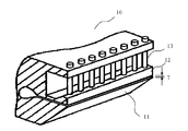
図1は、フィルムの製造のために一般に用いられるTダイ(フラットダイ、インラインスリットとも呼ばれる)を模式的に示す図である。Tダイ10は、上リップ12と下リップ11で構成されるリップを有し、リップの間からフィルム原料が押し出される。リップ間隔(T)は、ボルト13により調整される。
FIG. 1 is a diagram schematically showing a T die (also referred to as a flat die or an inline slit) generally used for manufacturing a film. The T-die 10 has a lip composed of an
図2は、Tダイの模式的平面図であり、図2に示すように、ボルト13は、Tダイの幅方向に複数個設けられ、各ボルトを調整することによりリップ間隔を制御することができる。その結果、押し出されたフィルム20、例えばポリイミドフィルムの製造であれば、フィルム状溶液の厚みの幅方向プロファイルを変更することができ、最終的に製品ポリイミドフィルムの厚みの幅方向プロファイルを変更することができる。また、ボルト13は、典型的には、手動操作とともに、自動制御による微調整が可能である。自動制御による微調整としては、例えば、加熱ヒータによる熱収縮を利用してリップ間隔を調整するヒートボルト方式による自動微調整システムが知られている。本発明は、このような自動微調整システムにより、ボルトを調整してリップ間隔の時間的制御を行う。
FIG. 2 is a schematic plan view of a T die. As shown in FIG. 2, a plurality of
本発明において、ボルト13を操作するにあたり、幅方向の全ボルトを、操作ブロックに区分する。操作ブロックは、リップ間隔の+制御指令(リップ間隔Tを大きくする)、−制御指令(リップ間隔Tを小さくする)に対して、同一の動きをする。これを、ブロック(1)〜ブロック(m)とし、任意のブロックをブロック(k)で表す(mおよびkは正の整数、1≦k<m)。ブロック(k)とブロック(k+1)は隣接するものとする。ブロック(1)〜ブロック(m)には、等しい数のボルトが含まれるようにしてもよいし、または使用する装置が有する特徴を考慮して、等しくない適切な数が含まれるようにしてもよい。例えば、両端を除いて等しいボルト数が各ブロックに含まれるようにする。
In the present invention, when operating the
いくつのボルトを一つのブロックに割り当てるかは、装置により異なり、少なくとも1個以上を含むようにすればよい。但し、多くのボルトを一つのブロックに割り当てると、フィルム幅方向でのブロック数(m)が小さくなり、厚みムラを有効に解消できなくなる。一つのブロックに含まれるボルトの数は、好ましくは1〜10、より好ましくは1〜5である。 The number of bolts assigned to one block differs depending on the device, and it is sufficient to include at least one or more. However, if many bolts are assigned to one block, the number of blocks (m) in the film width direction becomes small, and thickness unevenness cannot be effectively eliminated. The number of bolts contained in one block is preferably 1 to 10, more preferably 1 to 5.
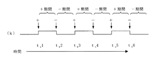
本発明において、あるブロック(k)に対しては、リップ間隔を開閉させる(間隔を増減させる)制御を行う。具体的には、図3のタイミングチャートに示すように、ブロック(k)に含まれるボルトに対して、時間tk1において、ΔTだけリップ間隔を開くように、+制御指令を出し、時間tk2において、ΔTだけリップ間隔を狭くするように、−制御指令を出す。ここで、+制御指令を受けると、ボルトはΔTだけリップ間隔を開く動作を行い、次の指令までこれを維持し(以下、+期間という。)、−制御指令を受けると、ボルトはΔTだけリップ間隔を狭くする動作を行い、次の指令までこの間隔を維持する(以下、−期間という。)。同様にして、時間tk3において+制御指令、時間tk4において−制御指令、時間tk5において+制御指令、時間tk6において−制御指令を出す。このような、+制御指令と−制御指令を繰り返すことで、ブロック(k)のボルトは、リップ間隔をΔTの範囲だけ変動させるように動作する。
In the present invention, a certain block (k) is controlled to open / close the lip interval (increase / decrease the interval). Specifically, as shown in the timing chart of FIG. 3, a + control command is issued for the bolt included in the block (k) so as to open the lip interval by ΔT at
+制御指令と−制御指令は、リップ間隔を変化させても、製品フィルムの厚み(1枚の厚み)が所定の許容範囲内に収まる範囲となるように設定する。 The + control command and the -control command are set so that the thickness of the product film (thickness of one sheet) falls within a predetermined allowable range even when the lip interval is changed.
ここで、+期間と−期間は、時間が等しい必要はないが、ある期間において、それぞれを合計したときには等しくなるように設定する。一般的には、+期間とその次の−期間の時間を等しくすることが好ましく、さらには、+期間とその次の+期間の時間を等しくすること、即ち、図3に示すように+期間と−期間が同じ時間で周期的に繰り返すことが好ましい。+期間と−期間の時間は、製造されるフィルムの種類、製造装置、その他の製造条件に依存して決めることが好ましいが、例えば数秒(例えば5秒)以上、好ましくは1分以上、より好ましくは5分以上、さらに好ましくは7分以上であり、例えば1日以下、好ましくは10時間以下、より好ましくは1時間以下、さらに好ましくは20分以下である。 Here, the + period and the-period need not be equal in time, but are set to be equal when they are totaled in a certain period. In general, it is preferable to equalize the time of the + period and the next-period, and further, equalize the time of the + period and the next + period, that is, as shown in FIG. It is preferable that the period is periodically repeated at the same time. The time of the + period and the − period is preferably determined depending on the type of film to be manufactured, the manufacturing apparatus, and other manufacturing conditions. For example, it is several seconds (for example, 5 seconds) or longer, preferably 1 minute or longer, and more preferably. Is 5 minutes or more, more preferably 7 minutes or more, for example, 1 day or less, preferably 10 hours or less, more preferably 1 hour or less, and even more preferably 20 minutes or less.
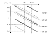
第1の実施形態では、ブロック(k)に隣接するブロック(k+1)において、特定の時間だけ遅れて、ブロック(k)と同一の動作を行うように制御指令を出す。即ち、図4のタイミングチャートに示すように、ブロック(k+1)に含まれるボルトに対して、時間t(k+1)1において+制御指令、時間t(k+1)2において−制御指令、時間t(k+1)3において+制御指令、時間t(k+1)4において−制御指令、・・・というように、ブロック(k)と同一の動作を行う制御指令を出す。従って、ブロック(k+1)の動作のブロック(k)の動作に対する遅れ時間は、常に一定である。この遅れ時間を、Δt(k+1)−kとすると、
Δt(k+1)−k =t(k+1)1−tk1=t(k+1)2−tk2=・・・=t(k+1)6−tk6=・・・
である。
In the first embodiment, in the block (k + 1) adjacent to the block (k), a control command is issued so as to perform the same operation as the block (k) with a delay of a specific time. That is, as shown in the timing chart of FIG. 4, block relative to (k + 1) to the bolt included, + control command at
Δt (k + 1) −k =
It is.
同様に、ブロック(k)からi個離れたブロック(k+i)においても、特定の時間だけ遅れて、ブロック(k)と同一の動作を行う。 Similarly, in the block (k + i) that is i blocks away from the block (k), the same operation as that of the block (k) is performed with a delay of a specific time.
図5に、全ブロックの動作制御指令の時間チャートの1例を示す。隣接するブロックからの遅れ時間Δt(k+1)−k=t(k+1)1−tk1は、+期間および−期間より、少なくとも短いことが必要であり、好ましくは+期間および−期間の1/2以下、より好ましくは1/2未満、さらに好ましくは+期間および−期間の1/3以下、最も好ましくは1/5以下である。隣接するブロックからの遅れ時間Δt(k+1)−kが、+期間および−期間より十分に短い場合、ブロック全体の動作の時間チャートにおいて、図5に見られるように、+制御指令および−制御指令は、番号の小さいブロックから番号の大きいブロックに向けて、波のように伝播している。その結果、局所的な厚みムラが隣接するブロックに流れるように拡散し、解消していくと推定される。
FIG. 5 shows an example of a time chart of operation control commands for all blocks. The delay time Δt (k + 1) −k =
図5では、隣接するブロックからの遅れ時間Δt(k+1)−kが、すべてのkに対して一定である例を示したが、Δt(k+1)−k(>0)が、ブロックによって異なってもよい。図6は、Δt(k+1)−kが、ブロック番号が大きくなるに従って短くなる例である。図7は、Δt(k+1)−kが、ブロック番号が大きくなるに従って長くなる例である。ただし、Δt(k+1)−kと、+期間および−期間との関係は、前述の関係(特に好ましい範囲)を満たすように設定される。 FIG. 5 shows an example in which the delay time Δt (k + 1) −k from an adjacent block is constant for all k, but Δt (k + 1) −k (> 0) varies depending on the block. Also good. FIG. 6 is an example in which Δt (k + 1) −k becomes shorter as the block number becomes larger. FIG. 7 is an example in which Δt (k + 1) −k becomes longer as the block number increases. However, the relationship between Δt (k + 1) −k , the + period, and the − period is set to satisfy the above-described relationship (particularly a preferable range).
この実施形態(第1の実施形態)では、前述のとおり、ブロック(k)に隣接するブロック(k+1)において、特定の時間だけ遅れて、ブロック(k)と同一の動作を行うように制御指令を出すことが特徴であるが、ブロック(k)に隣接するブロック(k−1)において、特定の時間だけ遅れて、ブロック(k)と同一の動作を行うとしても同じである。ブロック(k)に隣接するブロック(k−1)において、特定の時間だけ遅れる場合は、図5〜7において、左右を反転させたチャート、即ち、ブロック番号が大きい方から小さい方へ、+制御指令および−制御指令が波のように伝播する図となるのみである(ブロック番号を右から左に順に付けたと考えてもよい。)。 In this embodiment (first embodiment), as described above, in the block (k + 1) adjacent to the block (k), the control command is performed so as to perform the same operation as that of the block (k) with a specific time delay. However, in the block (k−1) adjacent to the block (k), the same operation is performed even if the same operation as the block (k) is performed with a delay of a specific time. When the block (k-1) adjacent to the block (k) is delayed by a specific time, in FIG. 5 to FIG. 7, the left and right charts are inverted, that is, the control is performed from the larger block number to the smaller block number. It is only a figure in which the command and the -control command propagate like a wave (it may be considered that block numbers are assigned in order from right to left).
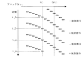
次に、第2の実施形態を、図8に示す。第2の実施形態では、特定のブロック(k0)を中心に、k0より番号の大きいブロック(k0+i)では、隣接するブロック(k0+i−1)より、特定の時間だけ遅れて、ブロック(k0)と同一の動作を行い、一方、k0より番号の小さいブロック(k0−j)では、隣接するブロック(k0−j+1)より、特定の時間だけ遅れて、ブロック(k0)と同一の動作を行うように制御指令を出す。ここで、k0、i、jは正の整数であり、mは前述のとおりブロックの数である。従って、各パラメータは次の関係を満たしている。 Next, a second embodiment is shown in FIG. In the second embodiment, centering on a specific block (k 0 ), a block (k 0 + i) having a number greater than k 0 is delayed by a specific time from an adjacent block (k 0 + i−1). , The same operation as that of the block (k 0 ), while the block (k 0 -j) having a smaller number than k 0 is delayed by a specific time from the adjacent block (k 0 -j + 1), and the block ( A control command is issued so as to perform the same operation as k 0 ). Here, k 0 , i, and j are positive integers, and m is the number of blocks as described above. Therefore, each parameter satisfies the following relationship.
1<k0<m
1≦(k0−j)< k0 <(k0+i)≦m
即ち、第2の実施形態では、k0より番号の大きいブロック(k0+i)では、第1の実施形態と同じ動作を行い、k0より番号の小さいブロック(k0−j)では、図5〜7において、左右を反転させたチャート、即ち、ブロック番号が大きい方から小さい方へ、+制御指令および−制御指令が波のように伝播する図となる。
1 <k 0 <m
1 ≦ (k 0 −j) <k 0 <(k 0 + i) ≦ m
That is, in the second embodiment, the k 0 from the number of large blocks (k 0 + i), it performs the same operation as the first embodiment, the smaller block than k 0 numbered (k 0 -j), FIG. 5 to 7 are charts in which left and right are reversed, that is, a diagram in which a + control command and a −control command are propagated like waves from a larger block number to a smaller block number.
図8では、ブロック(k0+i)における、隣接するブロック(k0+i−1)からの遅れ時間Δt(k0+i)−(k0+i−1)がすべてのiについて等しく、そしてブロック(k0−j)における、隣接するブロック(k0−j+1)からの遅れ時間Δt(k0−j)−(k0−j+1)がすべてのjについて等しく、かつΔt(k0+i)−(k0+i−1)=Δt(k0−j)−(k0−j+1)である場合を示し、これは好ましい形態の1つである。しかし、遅れ時間をブロックで異なるように設定してもよく、例えば異なるiまたはjにより、それぞれのブロックの遅れ時間を異なるように設定したり、Δt(k0+i)−(k0+i−1)≠Δt(k0−j)−(k0−j+1)となるように設定してもよい。例えば、図9のように、ブロックk0から離れるに従い、隣接するブロックからの遅れが大きくなるように設定してもよいし、図示しないが、ブロックk0から離れるに従い、隣接するブロックからの遅れが小さくなるように設定してもよい。 In Figure 8, at block (k 0 + i), the delay time Δt (k0 + i) from the adjacent blocks (k 0 + i-1) - (k0 + i-1) are equal for all i, and the block (k 0 -j ), The delay time Δt (k0−j) − (k0−j + 1) from the adjacent block (k 0 −j + 1) is equal for all j, and Δt (k0 + i) − (k0 + i−1) = Δt (k0 ) -J)-(k0-j + 1) , which is one of the preferred forms. However, the delay time may be set differently for each block. For example, the delay time of each block may be set differently depending on different i or j, or Δt (k0 + i) − (k0 + i−1) ≠ Δt ( k0-j)-(k0-j + 1) may be set. For example, as shown in FIG. 9, the delay from the adjacent block may be set to increase as the distance from the block k 0 increases. Although not illustrated, the delay from the adjacent block as the distance from the block k 0 increases. May be set to be small.
k0は、状況に応じていずれのブロックでも選択可能であるが、比較的中央のブロックに設定することが好ましく、例えば、式:
m/5 ≦ k0 ≦ 4m/5
を満たすように、好ましくは式:
m/4 ≦ k0 ≦ 3m/4
を満たすように、より好ましくは式:
m/3 ≦ k0 ≦ 2m/3
を満たすように設定する。
k 0 can be selected in any block depending on the situation, but is preferably set to a relatively central block. For example, the equation:
m / 5 ≦ k 0 ≦ 4 m / 5
Preferably satisfy the formula:
m / 4 ≦ k 0 ≦ 3 m / 4
More preferably, the formula:
m / 3 ≤ k 0 ≤ 2m / 3
Set to satisfy.
以上のように、本発明では、フィルム幅方向の膜厚プロファイルの測定と関係なく、上記のような、リップ間隔の自動制御を行うものである。しかし、本発明によるリップ間隔の自動制御に加えて、膜厚プロファイルの測定のフィードバックに基づく制御を重畳して行うこともできる。言い換えれば、通常のフィルム製造に利用されている複数の位置においてリップ間隔を調整可能なTダイよりフィルム原料を連続的に押し出し、得られるフィルムの幅方向プロファイルを測定し、プロファイル目標値と比較することによりTダイの押出しリップの間隙幅を自動調節するプロファイル自動制御を行っても、幅方向の厚みの均一性が解消しない場合や、幅方向に局所的に生じる厚みムラが解消しない場合に、該プロファイル自動制御にさらに本発明の製造方法を適用することにより、幅方向の厚みの均一性が解消しやすくなり、また幅方向に局所的に生じる厚みムラが解消しやすくなる。 As described above, in the present invention, the lip interval is automatically controlled as described above regardless of the measurement of the film thickness profile in the film width direction. However, in addition to the automatic control of the lip interval according to the present invention, the control based on the feedback of the measurement of the film thickness profile can be superposed. In other words, the film raw material is continuously extruded from a T-die capable of adjusting the lip interval at a plurality of positions used for normal film production, and the width direction profile of the obtained film is measured and compared with the profile target value. Even if the profile automatic control that automatically adjusts the gap width of the extrusion lip of the T die is performed, if the thickness uniformity in the width direction does not disappear or the thickness unevenness that occurs locally in the width direction does not disappear, By further applying the manufacturing method of the present invention to the profile automatic control, the thickness uniformity in the width direction can be easily eliminated, and the thickness unevenness locally generated in the width direction can be easily eliminated.
本発明は、幅方向や長さ方向に厚みのムラのないかまたは少ないフィルムを提供することができるので、製造された樹脂フィルムは種々の用途に使用できる。 Since the present invention can provide a film with little or no thickness unevenness in the width direction or the length direction, the produced resin film can be used for various applications.
本発明により製造された樹脂フィルムは、FPC、TAB、COF等の金属配線板などの用途で使用される絶縁基板材料として、金属配線またはICチップなどのチップ部材などのカバー基材として、さらには液晶ディスプレー、有機エレクトロルミネッセンスディスプレー、電子ペーパー、太陽電池などのベース基材として好適に用いることができる。 The resin film produced according to the present invention is used as an insulating substrate material used in metal wiring boards such as FPC, TAB, and COF, as a cover substrate such as a metal wiring or a chip member such as an IC chip, and more It can be suitably used as a base substrate for liquid crystal displays, organic electroluminescence displays, electronic paper, solar cells and the like.
金属配線板の基板用途として使用した場合、樹脂フィルムの表面に銅などの金属配線を形成し、その後、異方性導電接着フィルム(ACF)や金属接合(例えば、金金接合、金錫接合など)などにより、他の基板と接続したり、ICチップなどのチップ部材を搭載するなどして電子・電気部品を製造することができる。 When used as a substrate for a metal wiring board, a metal wiring such as copper is formed on the surface of a resin film, and then an anisotropic conductive adhesive film (ACF) or metal bonding (for example, gold-metal bonding, gold-tin bonding, etc.) ) Etc., electronic / electrical components can be manufactured by connecting to other substrates or mounting a chip member such as an IC chip.
本発明により製造された樹脂フィルムの片面または両面に、接着剤、感光性素材、熱圧着性素材などを積層して、樹脂フィルムの積層体を得ることができる。また、本発明の樹脂フィルムの片面または両面に、直接または接着剤層を介して、銅などの金属層を設けることができる。 A laminated body of resin films can be obtained by laminating an adhesive, a photosensitive material, a thermocompression bonding material or the like on one or both surfaces of the resin film produced according to the present invention. Moreover, metal layers, such as copper, can be provided in the single side | surface or both surfaces of the resin film of this invention directly or through an adhesive layer.
本発明により製造される樹脂フィルムを巻き取り得られる製品ロールは、巻こぶが少なく、そのため巻ずれの発生によるすり傷の発生が少ない。そして、比較的均一に巻き上げられているために、長期保存しても、多角形化する程度も小さい。また、フィルムの厚みムラも少ないため、ハイエッジが発生し難くなる。 The product roll obtained by winding up the resin film produced according to the present invention has less humps, and hence less scratches due to the occurrence of winding deviation. And since it is wound up comparatively uniformly, even if it preserve | saves for a long period of time, the extent which becomes polygonal is also small. Moreover, since there is little film thickness nonuniformity, it becomes difficult to generate a high edge.
そのため本発明の樹脂フィルムを500m以上の長さ、好ましくは1000m〜6000m、さらに好ましくは1500m〜5000m、特に好ましくは2000m〜4000mの長さを巻き取られた製品ロールを得ることができる。 Therefore, a product roll in which the resin film of the present invention has a length of 500 m or more, preferably 1000 m to 6000 m, more preferably 1500 m to 5000 m, and particularly preferably 2000 m to 4000 m can be obtained.
<ポリイミドフィルムの製造への応用>
本発明は、種々のフィルムの製造に適用が可能であり、溶融押出成形に適用することもできるが、溶液キャスト法による製造方法に適用することがより好ましい。これは、リップ間隔をΔTの範囲で変動させても、Tダイより押し出されるフィルム原料が溶媒を含む場合には、溶媒が蒸発して厚みが減少するだけ、許容厚みに対する影響が小さいからである。
<Application to production of polyimide film>
The present invention can be applied to the production of various films and can also be applied to melt extrusion molding, but is more preferably applied to a production method by a solution cast method. This is because even if the lip interval is varied within the range of ΔT, if the film raw material extruded from the T die contains a solvent, the solvent is evaporated and the thickness is reduced, so that the influence on the allowable thickness is small. .
特に、本発明をポリイミドフィルムの製造に適用することが好ましい。ポリイミドフィルムの製造方法は、ポリアミック酸溶液組成物(以下、ポリイミド前駆体溶液という)を支持体上にキャストし、自己支持性フィルムとする第1工程と、前記自己支持性フィルムを搬送しながら、加熱処理する第2工程(キュア工程)とを有する。 In particular, it is preferable to apply the present invention to the production of a polyimide film. The manufacturing method of a polyimide film is a first step in which a polyamic acid solution composition (hereinafter referred to as a polyimide precursor solution) is cast on a support to form a self-supporting film, and while transporting the self-supporting film, And a second step (curing step) for heat treatment.
本発明は、ポリイミドフィルム製造の第1工程において、ポリイミド前駆体溶液をTダイより押出して、支持体上にキャストする際に使用される。Tダイのリップ間隔を前述のように制御することで、自己支持性フィルムの厚みムラが小さくなり、その結果ポリイミドフィルムの厚みムラが小さくなり、製品ロールとしたときに、巻こぶや多角形化の発生の少ない製品が得られる。 The present invention is used when a polyimide precursor solution is extruded from a T-die and cast on a support in the first step of producing a polyimide film. By controlling the lip interval of the T-die as described above, the thickness unevenness of the self-supporting film is reduced, and as a result, the thickness unevenness of the polyimide film is reduced. A product with less occurrence of
最終的に製造されるポリイミドフィルムは、1層で構成されても、成分の異なる多層で構成されてもよい。ポリイミドフィルムを構成する層のうちで少なくとも1層は、耐熱性ポリイミドで構成される層であることが好ましい。多層構造の例としては、耐熱性ポリイミドで構成される層の片面または両面に熱圧着性ポリイミドで構成される層が形成された例、表面が平滑性に優れる層と他面が易滑性に優れる層で形成された例、少なくとも1層が透明性又は非透明性に優れる層で形成された例、などが挙げられる。最終的に製造されるポリイミドフィルムに対応して、自己支持性フィルムも、1層で構成されても、ポリイミド前駆体の成分が異なる多層で構成されてもよい。 The finally produced polyimide film may be composed of one layer or multiple layers having different components. Of the layers constituting the polyimide film, at least one layer is preferably a layer composed of heat-resistant polyimide. As an example of a multilayer structure, a layer composed of thermocompression bonding polyimide is formed on one side or both sides of a layer composed of heat-resistant polyimide, a layer with excellent surface smoothness and a non-slip surface on the other side Examples where the layer is formed with an excellent layer, examples where at least one layer is formed with a layer having excellent transparency or non-transparency, and the like are included. Corresponding to the finally produced polyimide film, the self-supporting film may also be composed of one layer, or may be composed of multiple layers having different polyimide precursor components.
以下の説明では、耐熱性に優れる1層構造のポリイミドフィルムの製造方法を例にして説明する。2層以上の層でポリイミドフィルムが構成され、Tダイからの押出によるキャストが2回以上(別々でも同時でもよい)実施されるならば、その2回以上のキャストの全部または1回以上を、本発明の方法により実施することができる。 In the following description, a method for producing a single-layer polyimide film having excellent heat resistance will be described as an example. If a polyimide film is composed of two or more layers and casting by extrusion from a T-die is performed two or more times (separate or simultaneous), all or one or more of the two or more castings are performed, It can be carried out by the method of the present invention.
自己支持性フィルムは、半硬化状態またはそれ以前の乾燥状態である。この半硬化状態またはそれ以前の乾燥状態とは、加熱および/または化学イミド化によって自己支持性の状態にあることを意味する。自己支持性フィルムは、支持体から剥がせるものであればよく、溶媒含量(加熱減量)やイミド化率はどのような範囲であってもよい。自己支持性フィルムの溶媒含量およびイミド化率は、製造を意図するポリイミドフィルムにより適宜設定される。 The self-supporting film is in a semi-cured state or in a dried state before that. This semi-cured state or a dry state before it means that it is in a self-supporting state by heating and / or chemical imidization. The self-supporting film may be any film that can be peeled off from the support, and the solvent content (heat loss) and imidation ratio may be in any range. The solvent content and imidization rate of the self-supporting film are appropriately set depending on the polyimide film intended for production.
ポリイミドフィルムは、テトラカルボン酸成分と、ジアミン成分とを反応させて得られるものであり、熱イミド化、化学イミド化、または熱イミド化と化学イミド化とを併用した方法で製造することができる。 The polyimide film is obtained by reacting a tetracarboxylic acid component and a diamine component, and can be produced by thermal imidization, chemical imidization, or a method that combines thermal imidization and chemical imidization. .
本発明のポリイミドフィルムを製造する方法としては、
(1)ポリアミック酸溶液、またはポリアミック酸溶液に必要に応じてイミド化触媒、有機リン含有化合物、無機微粒子などを選択して加えたポリアミック酸溶液組成物をフィルム状に支持体上に流延し、加熱乾燥して自己支持性フィルムを得た後、熱的に脱水環化、脱溶媒させてポリイミドフィルムを得る方法、
(2)ポリアミック酸溶液に環化触媒及び脱水剤を加え、さらに必要に応じて無機微粒子などを選択して加えたポリアミック酸溶液組成物をフィルム状に支持体上に流延し、化学的に脱水環化させて、必要に応じて加熱乾燥して自己支持性フィルムを得た後、これを加熱脱溶媒、イミド化することによりポリイミドフィルムを得る方法
が挙げられる。
As a method for producing the polyimide film of the present invention,
(1) A polyamic acid solution or a polyamic acid solution composition in which an imidization catalyst, an organic phosphorus-containing compound, inorganic fine particles, etc. are selected and added to a polyamic acid solution as necessary is cast on a support in the form of a film. , After drying by heating to obtain a self-supporting film, thermally dehydrating cyclization, removing the solvent to obtain a polyimide film,
(2) A cyclization catalyst and a dehydrating agent are added to the polyamic acid solution, and the polyamic acid solution composition added by selecting inorganic fine particles and the like as necessary is cast on a support in a film form. A method of obtaining a polyimide film by dehydrating and cyclizing and heat-drying as necessary to obtain a self-supporting film, followed by heat desolvation and imidization can be mentioned.
<第1工程>
ポリイミド前駆体溶液を支持体上にキャストし、自己支持性フィルムとする第1工程を最初に説明する。
<First step>
The first step of casting the polyimide precursor solution on the support to form a self-supporting film will be described first.
まず、有機溶媒中でテトラカルボン酸成分とジアミン成分とを反応させて、ポリイミド前駆体であるポリアミック酸を合成する。次に、得られたポリイミド前駆体の溶液に必要であればイミド化触媒、有機リン化合物や無機微粒子を加えた後、支持体上にキャストし、加熱・乾燥して、自己支持性フィルムを製造する。 First, a tetracarboxylic acid component and a diamine component are reacted in an organic solvent to synthesize a polyamic acid that is a polyimide precursor. Next, if necessary, an imidation catalyst, an organic phosphorus compound and inorganic fine particles are added to the obtained polyimide precursor solution, and then cast on a support, heated and dried to produce a self-supporting film. To do.
上記テトラカルボン酸成分としては、芳香族テトラカルボン酸二無水物、脂肪族テトラカルボン酸二無水物、脂環式テトラカルボン酸二無水物等を挙げることができる。具体例としては、3,3’,4,4’−ビフェニルテトラカルボン酸二無水物、ピロメリット酸二無水物、3,3’,4,4’−オキシジフタル酸二無水物、ジフェニルスルホン−3,4,3’,4’−テトラカルボン酸二無水物、ビス(3,4−ジカルボキシフェニル)スルフィド二無水物、2,2−ビス(3,4−ジカルボキシフェニル)−1,1,1,3,3,3−ヘキサフルオロプロパン二無水物等の芳香族テトラカルボン酸二無水物が挙げられる。 Examples of the tetracarboxylic acid component include aromatic tetracarboxylic dianhydrides, aliphatic tetracarboxylic dianhydrides, alicyclic tetracarboxylic dianhydrides, and the like. Specific examples include 3,3 ′, 4,4′-biphenyltetracarboxylic dianhydride, pyromellitic dianhydride, 3,3 ′, 4,4′-oxydiphthalic dianhydride, diphenylsulfone-3. , 4,3 ′, 4′-tetracarboxylic dianhydride, bis (3,4-dicarboxyphenyl) sulfide dianhydride, 2,2-bis (3,4-dicarboxyphenyl) -1,1, Aromatic tetracarboxylic dianhydrides such as 1,3,3,3-hexafluoropropane dianhydride are exemplified.
上記ジアミン成分としては、芳香族ジアミン、脂肪族ジアミン、脂環式ジアミン等を挙げることができる。具体例としては、p−フェニレンジアミン、4,4’−ジアミノジフェニルエーテル、3,4’−ジアミノジフェニルエーテル、m−トリジン、p−トリジン、5−アミノ−2−(p−アミノフェニル)ベンゾオキサゾール、4,4’−ジアミノベンズアニリド、1,3−ビス(4−アミノフェノキシ)ベンゼン、1,4−ビス(3−アミノフェノキシ)ベンゼン、1,4−ビス(4−アミノフェノキシ)ベンゼン、3,3’−ビス(3−アミノフェノキシ)ビフェニル、3,3’−ビス(4−アミノフェノキシ)ビフェニル、4,4’−ビス(3−アミノフェノキシ)ビフェニル、4,4’−ビス(4−アミノフェノキシ)ビフェニル、ビス〔3−(3−アミノフェノキシ)フェニル〕エーテル、ビス〔3−(4−アミノフェノキシ)フェニル〕エーテル、ビス〔4−(3−アミノフェノキシ)フェニル〕エーテル、ビス〔4−(4−アミノフェノキシ)フェニル〕エーテル、2,2−ビス〔3−(3−アミノフェノキシ)フェニル〕プロパン、2,2−ビス〔3−(4−アミノフェノキシ)フェニル〕プロパン、2,2−ビス〔4−(3−アミノフェノキシ)フェニル〕プロパン、2,2−ビス〔4−(4−アミノフェノキシ)フェニル〕プロパン等の芳香族ジアミンが挙げられる。 Examples of the diamine component include aromatic diamines, aliphatic diamines, and alicyclic diamines. Specific examples include p-phenylenediamine, 4,4′-diaminodiphenyl ether, 3,4′-diaminodiphenyl ether, m-tolidine, p-tolidine, 5-amino-2- (p-aminophenyl) benzoxazole, 4 , 4′-diaminobenzanilide, 1,3-bis (4-aminophenoxy) benzene, 1,4-bis (3-aminophenoxy) benzene, 1,4-bis (4-aminophenoxy) benzene, 3,3 '-Bis (3-aminophenoxy) biphenyl, 3,3'-bis (4-aminophenoxy) biphenyl, 4,4'-bis (3-aminophenoxy) biphenyl, 4,4'-bis (4-aminophenoxy) ) Biphenyl, bis [3- (3-aminophenoxy) phenyl] ether, bis [3- (4-aminophenoxy) phene Ether], bis [4- (3-aminophenoxy) phenyl] ether, bis [4- (4-aminophenoxy) phenyl] ether, 2,2-bis [3- (3-aminophenoxy) phenyl] propane, 2,2-bis [3- (4-aminophenoxy) phenyl] propane, 2,2-bis [4- (3-aminophenoxy) phenyl] propane, 2,2-bis [4- (4-aminophenoxy) And aromatic diamines such as phenyl] propane.
テトラカルボン酸成分とジアミン成分との組み合わせの一例としては、以下の1)〜3)が、機械的特性に優れ、高い剛性と優れた寸法安定性を有するフィルムが得られやすく、配線基板などの各種基板に好適に用いることができる。 As an example of a combination of a tetracarboxylic acid component and a diamine component, the following 1) to 3) are excellent in mechanical properties, and a film having high rigidity and excellent dimensional stability is easily obtained. It can be suitably used for various substrates.
1)3,3’,4,4’−ビフェニルテトラカルボン酸二無水物と、p−フェニレンジアミン、又はp−フェニレンジアミン及び4,4−ジアミノジフェニルエ−テル(例えば、PPD/DADE(モル比)は100/0〜85/15であることが好ましい。)との組み合わせ。 1) 3,3 ′, 4,4′-biphenyltetracarboxylic dianhydride and p-phenylenediamine, or p-phenylenediamine and 4,4-diaminodiphenyl ether (for example, PPD / DADE (molar ratio) ) Is preferably 100/0 to 85/15.)).
2)3,3’,4,4’−ビフェニルテトラカルボン酸二無水物及びピロメリット酸二無水物(例えば、s−BPDA/PMDA(モル比)は、99/1〜0/100、さらに97/3〜70/30、特に95/5〜80/20であることが好ましい)と、p−フェニレンジアミン、又はp−フェニレンジアミン及び4,4−ジアミノジフェニルエ−テル(例えば、PPD/DADE(モル比)は90/10〜10/90であることが好ましい。)との組み合わせ。 2) 3,3 ′, 4,4′-biphenyltetracarboxylic dianhydride and pyromellitic dianhydride (for example, s-BPDA / PMDA (molar ratio) is 99/1 to 0/100, and 97 / 3-70 / 30, preferably 95/5 to 80/20) and p-phenylenediamine, or p-phenylenediamine and 4,4-diaminodiphenyl ether (for example, PPD / DADE ( The molar ratio) is preferably 90/10 to 10/90.)
3)ピロメリット酸二無水物と、p−フェニレンジアミン及び4,4−ジアミノジフェニルエ−テル(例えば、PPD/DADE(モル比)は90/10〜10/90であることが好ましい。)との組み合わせ。 3) pyromellitic dianhydride, p-phenylenediamine and 4,4-diaminodiphenyl ether (for example, PPD / DADE (molar ratio) is preferably 90/10 to 10/90). Combination.
テトラカルボン酸成分とジアミン成分との組み合わせは、上記1)と2)、さらに上記1)であることが好ましい。 The combination of the tetracarboxylic acid component and the diamine component is preferably 1) and 2) above, and further 1) above.
中でも、3,3’,4,4’−ビフェニルテトラカルボン酸二無水物(以下単にs−BPDAと略記することもある。)を主成分とするテトラカルボン酸成分と、パラフェニレンジアミン(以下単にPPDと略記することもある。)を主成分とするジアミン成分とから製造されるポリイミド前駆体が好ましい。具体的には、s−BPDAを70モル%以上、より好ましくは80モル%以上、特に好ましくは90モル%以上、さらに好ましくは95モル%以上含むテトラカルボン酸成分が好ましく、PPDを70モル%以上、より好ましくは80モル%以上、特に好ましくは90モル%以上、さらに好ましくは95モル%以上含むジアミン成分が好ましい。このようなテトラカルボン酸成分とジアミン成分とからは機械的特性に優れ、高い剛性と優れた寸法安定性を有するフィルムが得られやすく、配線基板などの各種基板に好適に用いることができる。 Among them, a tetracarboxylic acid component mainly composed of 3,3 ′, 4,4′-biphenyltetracarboxylic dianhydride (hereinafter sometimes simply referred to as s-BPDA) and paraphenylenediamine (hereinafter simply referred to as “s-BPDA”). A polyimide precursor produced from a diamine component whose main component is sometimes abbreviated as PPD) is preferred. Specifically, a tetracarboxylic acid component containing 70 mol% or more of s-BPDA, more preferably 80 mol% or more, particularly preferably 90 mol% or more, and still more preferably 95 mol% or more is preferable, and PPD is 70 mol%. More preferably, the diamine component is more preferably 80 mol% or more, particularly preferably 90 mol% or more, and still more preferably 95 mol% or more. From such a tetracarboxylic acid component and a diamine component, a film having excellent mechanical properties, high rigidity and excellent dimensional stability is easily obtained, and can be suitably used for various substrates such as a wiring substrate.
さらに、本発明の特性を損なわない範囲で、他のテトラカルボン酸および他のジアミンを用いることもできる。 Furthermore, other tetracarboxylic acids and other diamines can be used as long as the characteristics of the present invention are not impaired.
ポリイミド前駆体の合成は、有機溶媒中で、略等モルの芳香族テトラカルボン酸二無水物と芳香族ジアミンとをランダム重合またはブロック重合することによって達成される。また、予めどちらかの成分が過剰である2種類以上のポリイミド前駆体を合成しておき、各ポリイミド前駆体溶液を一緒にした後反応条件下で混合してもよい。このようにして得られたポリイミド前駆体溶液はそのまま、あるいは必要であれば溶媒を除去または加えて、自己支持性フィルムの製造に使用することができる。 The synthesis of the polyimide precursor is achieved by random polymerization or block polymerization of approximately equimolar aromatic tetracarboxylic dianhydride and aromatic diamine in an organic solvent. May also be mixed with the reaction conditions was keep two or more polyimide precursors in which either of these two components is excessive, the respective polyimide precursor solution together. The polyimide precursor solution thus obtained can be used for the production of a self-supporting film as it is or after removing or adding a solvent if necessary.
ポリイミド前駆体溶液の粘度は、製造する目的に応じて適宜選択すればよく、ポリアミック酸(ポリイミド前駆体)溶液は、30℃で測定した回転粘度が、約100〜5000ポイズ、特に500〜4000ポイズ、さらに好ましくは1500〜3500ポイズ程度のものであることが、このポリアミック酸溶液を取り扱う作業性の面から好ましい。したがって、前記の重合反応は、生成するポリアミック酸が上記のような粘度を示す程度にまで実施することが望ましい。 The viscosity of the polyimide precursor solution may be appropriately selected according to the purpose of production, and the polyamic acid (polyimide precursor) solution has a rotational viscosity measured at 30 ° C. of about 100 to 5000 poise, particularly 500 to 4000 poise. More preferably, it is about 1500 to 3500 poise from the viewpoint of workability in handling this polyamic acid solution. Therefore, it is desirable to carry out the polymerization reaction to such an extent that the produced polyamic acid exhibits the above viscosity.
ポリイミド前駆体溶液の有機溶媒としては、N−メチル−2−ピロリドン、N,N−ジメチルホルムアミド、N,N−ジメチルアセトアミド、N,N−ジエチルアセトアミドなどが挙げられる。これらの有機溶媒は単独で用いてもよく、2種以上を併用してもよい。 Examples of the organic solvent for the polyimide precursor solution include N-methyl-2-pyrrolidone, N, N-dimethylformamide, N, N-dimethylacetamide, N, N-diethylacetamide and the like. These organic solvents may be used alone or in combination of two or more.
ポリイミド前駆体溶液には、必要に応じて、熱イミド化であればイミド化触媒、有機リン含有化合物、無機微粒子などを加えてもよい。 If necessary, an imidization catalyst, an organic phosphorus-containing compound, inorganic fine particles, and the like may be added to the polyimide precursor solution as long as it is thermal imidization.
ポリイミド前駆体溶液には、必要に応じて、化学イミド化であれば環化触媒及び脱水剤、無機微粒子などを加えてもよい。 If necessary, a cyclization catalyst, a dehydrating agent, inorganic fine particles, and the like may be added to the polyimide precursor solution as long as it is chemical imidization.
イミド化触媒、有機リン含有化合物、化学イミド化の場合の環化触媒、化学イミド化の場合の脱水剤、無機微粒子等は、公知の物質、材料を適宜必要な量で使用することができる。 For the imidization catalyst, the organic phosphorus-containing compound, the cyclization catalyst in the case of chemical imidation, the dehydrating agent in the case of chemical imidation, inorganic fine particles, etc., known substances and materials can be used in necessary amounts as appropriate.
ポリイミド前駆体溶液の自己支持性フィルムは、上記のようなポリイミド前駆体の有機溶媒溶液、あるいはこれにイミド化触媒、有機リン含有化合物、無機微粒子などを加えたポリイミド前駆体溶液組成物を支持体上に流延塗布し、自己支持性となる程度(通常のキュア工程前の段階を意味する)、例えば支持体上より剥離することができる程度に加熱して製造される。 The self-supporting film of the polyimide precursor solution is a support of the polyimide precursor organic solvent solution as described above or a polyimide precursor solution composition in which an imidization catalyst, an organic phosphorus-containing compound, inorganic fine particles, and the like are added. It is manufactured by heating to such an extent that it is cast onto the substrate and becomes self-supporting (meaning a stage prior to a normal curing step), for example, can be peeled off from the support.
ポリイミド前駆体溶液は、ポリイミド前駆体を10〜30質量%程度含むものが好ましい。また、ポリイミド前駆体溶液としては、ポリマー濃度が8〜25質量%程度であるものが好ましい。 The polyimide precursor solution preferably contains about 10 to 30% by mass of the polyimide precursor. Moreover, as a polyimide precursor solution, the thing whose polymer concentration is about 8-25 mass% is preferable.
このときの加熱温度および加熱時間は適宜決めることができ、熱イミド化では、例えば、温度100〜180℃で1〜60分間程度加熱すればよい。化学イミド化では、例えば40〜200℃の温度で自己支持性となる程度にまで加熱する。 The heating temperature and heating time at this time can be determined as appropriate. In thermal imidization, for example, the heating may be performed at a temperature of 100 to 180 ° C. for about 1 to 60 minutes. In the chemical imidization, for example, heating is performed to a degree of self-supporting at a temperature of 40 to 200 ° C.
支持体としては、平滑な基材を用いることが好ましく、例えばステンレス基板、ステンレスベルトなどが使用される。連続生産するためには、エンドレスベルトなどのエンドレスな基材が好ましい。 As the support, it is preferable to use a smooth base material, for example, a stainless steel substrate, a stainless steel belt, or the like. For continuous production, an endless base material such as an endless belt is preferable.
自己支持性フィルムは、支持体上より剥離することができる程度にまで溶媒が除去され、および/またはイミド化されていれば特に限定されないが、熱イミド化では、その加熱減量が20〜50質量%の範囲にあること、さらに加熱減量が20〜50質量%の範囲で且つイミド化率が8〜55%の範囲にあることが、自己支持性フィルムの力学的性質が十分となり、好ましい。また、自己支持性フィルムの上面にカップリング剤の溶液を塗工する場合には、カップリング剤溶液をきれいに塗布しやすくなり、イミド化後に得られるポリイミドフィルムに発泡、亀裂、クレーズ、クラック、ひびワレなどの発生が観察されないために好ましい。 The self-supporting film is not particularly limited as long as the solvent is removed and / or imidized to such an extent that it can be peeled off from the support, but in thermal imidization, the loss on heating is 20 to 50 mass. %, And a weight loss by heating in the range of 20 to 50% by mass and an imidization ratio in the range of 8 to 55% are preferable because the mechanical properties of the self-supporting film are sufficient. In addition, when a coupling agent solution is applied to the upper surface of the self-supporting film, it becomes easy to apply the coupling agent solution cleanly, and the polyimide film obtained after imidization is foamed, cracked, crazed, cracked, cracked. This is preferable because occurrence of cracks or the like is not observed.
なお、上記の自己支持性フィルムの加熱減量とは、自己支持性フィルムの質量W1とキュア後のフィルムの質量W2とから次式によって求めた値である。 The heating loss of the self-supporting film is a value obtained from the following formula from the mass W1 of the self-supporting film and the mass W2 of the cured film.
加熱減量(質量%)={(W1−W2)/W1}×100 Heat loss (mass%) = {(W1-W2) / W1} × 100
また、上記の自己支持性フィルムのイミド化率は、IR(ATR)で測定し、フィルムとフルキュア品との振動帯ピーク面積または高さの比を利用して、イミド化率を算出することができる。振動帯ピークとしては、イミドカルボニル基の対称伸縮振動帯やベンゼン環骨格伸縮振動帯などを利用する。またイミド化率測定に関し、特開平9−316199号公報に記載のカールフィッシャー水分計を用いる手法もある。 Further, the imidization rate of the above self-supporting film can be measured by IR (ATR), and the imidization rate can be calculated using the ratio of the vibration band peak area or height between the film and the fully cured product. it can. As the vibration band peak, a symmetric stretching vibration band of an imidecarbonyl group, a benzene ring skeleton stretching vibration band, or the like is used. Further, regarding the imidization rate measurement, there is also a method using a Karl Fischer moisture meter described in JP-A-9-316199.
本発明においては、このようにして得られた自己支持性フィルムの片面または両面に、必要に応じて、カップリング剤やキレート剤などの表面処理剤の溶液を塗布してもよい。 In this invention, you may apply | coat the solution of surface treating agents, such as a coupling agent and a chelating agent, to the single side | surface or both surfaces of the self-supporting film obtained in this way as needed.
以上のようにして、第1工程において製造された自己支持性フィルムは、第2工程に送られる。 As described above, the self-supporting film produced in the first step is sent to the second step.
<第2工程>
第2工程(キュア工程)においては、第1工程で製造した自己支持性フィルムを、加熱処理(熱キュア)して目的のポリイミドフィルムとする。このとき、必要に応じてフィルムを延伸してもよい。
<Second step>
In the second step (curing step), the self-supporting film produced in the first step is subjected to heat treatment (thermal curing) to obtain a target polyimide film. At this time, the film may be stretched as necessary.
第2工程における加熱処理の温度プロファイルは、目的とするポリイミドフィルムの物性に合わせて適宜設定することができる。 The temperature profile of the heat treatment in the second step can be appropriately set according to the physical properties of the target polyimide film.
加熱処理の温度プロファイルの一例を挙げると、最高温度が、200〜600℃の範囲、好ましくは350〜550℃の範囲、特に好ましくは400〜500℃の範囲となるような条件で、例えば約0.05〜5時間で徐々に加熱されることが好ましい。好ましくは最終的に得られるポリイミドフィルム中の有機溶媒および生成水等からなる揮発物の含有量が1重量%以下になるように、自己支持性フィルムから溶媒などを充分に除去するとともに前記フィルムを構成しているポリマーのイミド化を充分に行う。 An example of the temperature profile of the heat treatment is as follows. The maximum temperature is in the range of 200 to 600 ° C, preferably in the range of 350 to 550 ° C, particularly preferably in the range of 400 to 500 ° C. It is preferable that heating is gradually performed in 0.05 to 5 hours. Preferably the solvent is sufficiently removed from the self-supporting film so that the content of volatile substances composed of an organic solvent and product water in the finally obtained polyimide film is 1% by weight or less, and the film is The imidation of the polymer which comprises is fully performed.
加熱ゾーンは、温度勾配を有していることも好ましく、また加熱温度の異なるいくつかブロックに分かれていてもよい。1例を挙げると、約100〜170℃の比較的低い温度で約0.5〜30分間第一次加熱処理し、次いで170〜220℃の温度で約0.5〜30分間第二次加熱処理して、その後、220〜400℃の高温で約0.5〜30分間第三次加熱処理し、必要により400〜600℃の高い温度で第四次高温加熱処理する。また、別の1例では、80〜240℃で第一次加熱処理し、必要により中間加熱温度で加熱処理し、350〜600℃で最終加熱処理する。 The heating zone preferably has a temperature gradient, and may be divided into several blocks having different heating temperatures. For example, the primary heat treatment is performed at a relatively low temperature of about 100 to 170 ° C. for about 0.5 to 30 minutes, and then the secondary heating is performed at a temperature of 170 to 220 ° C. for about 0.5 to 30 minutes. Then, a third heat treatment is performed at a high temperature of 220 to 400 ° C. for about 0.5 to 30 minutes, and a fourth high temperature heat treatment is performed at a high temperature of 400 to 600 ° C. if necessary. In another example, primary heat treatment is performed at 80 to 240 ° C., heat treatment is performed at an intermediate heating temperature as necessary, and final heat treatment is performed at 350 to 600 ° C.
上記の加熱処理は、熱風炉、赤外線加熱炉などの公知の種々の加熱装置を使用して行うことができる。フィルムの初期加熱温度、中間加熱温度および/または最終加熱温度などの加熱処理は、窒素、アルゴンなどの不活性ガスや、空気などの加熱ガス雰囲気下で行うことが好ましい。 Said heat processing can be performed using well-known various heating apparatuses, such as a hot air furnace and an infrared heating furnace. Heat treatment such as initial heating temperature, intermediate heating temperature, and / or final heating temperature of the film is preferably performed in an inert gas atmosphere such as nitrogen or argon, or a heating gas atmosphere such as air.
第2工程(キュア工程)における熱処理は、好ましくは所定の加熱ゾーンを有するキュア炉の中を、例えばテンター装置により自己支持性フィルムを連続して搬送し、その間に必要により、幅方向を拡大または縮小することで、延伸または緩和を行うことができる。 In the heat treatment in the second step (curing step), preferably, a self-supporting film is continuously conveyed in a curing furnace having a predetermined heating zone, for example, by a tenter device, and the width direction is expanded or extended as necessary. By reducing, stretching or relaxation can be performed.
テンター装置としては、加熱処理の間、自己支持性フィルムの幅方向の両端を把持しながら搬送できるものであればよく、フィルム把持部材として突き刺しピンを使用する(ピン式テンター)、クリップまたはチャックにより自己支持性フィルムの端部を把持するクリップ式テンター、チャック式テンター等を使用することができる。 Any tenter device may be used as long as it can be conveyed while gripping both ends in the width direction of the self-supporting film during the heat treatment, and a piercing pin is used as a film gripping member (pin type tenter) by a clip or a chuck A clip-type tenter, a chuck-type tenter or the like that grips the end of the self-supporting film can be used.
以上の製造方法により、ポリイミドフィルムは長尺状に製造されるので、一般的には、テンター装置により幅方向に把持したフィルムの両端部を切断除外した部分を、ロール状に巻いて、製品ロールとされる。 Since the polyimide film is produced in a long shape by the above production method, in general, a portion obtained by cutting and excluding both ends of the film held in the width direction by the tenter device is wound into a roll shape, and a product roll It is said.
ポリイミドフィルムの厚みは、適宜選択すればよく特に限定されるものではないが、厚さが150μm以下、好ましくは5〜120μm、より好ましくは6〜50μm、さらに好ましくは7〜40μm、特に好ましくは8〜35μmとすることができる。 The thickness of the polyimide film is not particularly limited as long as it is appropriately selected. The thickness is 150 μm or less, preferably 5 to 120 μm, more preferably 6 to 50 μm, still more preferably 7 to 40 μm, and particularly preferably 8. It can be set to ˜35 μm.
フィルム幅方向の膜厚プロファイル測定値を利用してTダイの押出しリップの間隙幅を自動調節するプロファイル自動制御のみで製造されるポリイミドフィルムに対して、本発明の製造方法をさらに適用して製造されたポリイミドフィルムは、幅方向の厚みの均一性が優れる。そのため本発明により製造されたポリイミドフィルムの製品ロールは、巻こぶが少なく、そのため巻ずれの発生によるすり傷の発生が少ない。そして、比較的均一に巻き上げられているために、長期保存しても、多角形化する程度も小さい。また、フィルムの厚みムラも少ないため、ハイエッジが発生し難くなる。 Manufactured by further applying the manufacturing method of the present invention to a polyimide film manufactured only by profile automatic control that automatically adjusts the gap width of the extrusion lip of the T die using the film thickness profile measurement value in the film width direction. The resulting polyimide film is excellent in thickness uniformity in the width direction. Therefore, the product roll of the polyimide film manufactured according to the present invention has less humps, and hence less scratches due to the occurrence of winding slip. And since it is wound up comparatively uniformly, even if it preserve | saves for a long period of time, the extent which becomes polygonal is also small. Moreover, since there is little film thickness nonuniformity, it becomes difficult to generate a high edge.
次に、実施例によって本発明を更に説明する。なお、本発明は以下の実施例に限定されるものではない。 Next, the present invention will be further described with reference to examples. In addition, this invention is not limited to a following example.
<実施例1>
重合槽に所定量のN,N−ジメチルアセトアミドを加え、次いで3,3’,4,4’−ビフェニルテトラカルボン二無水物、次いでパラフェニレンジアミンを加え、30℃で10時間重合反応させて、ポリマーの対数粘度(測定温度:30℃、濃度:0.5g/100ml溶媒、溶媒:N,N−ジメチルアセトアミド)が1.60、ポリマー濃度が18質量%であるポリイミド前駆体溶液を得た。このポリイミド前駆体溶液に、ポリイミド前駆体100質量部に対して0.1質量部の割合でモノステアリルリン酸エステルトリエタノールアミン塩および0.5質量部の割合で平均粒径0.08μmのコロイダルシリカを添加し、均一に混合してポリイミド前駆体溶液組成物を得た。このポリイミド前駆体溶液組成物の回転粘度は3000ポイズであった。
<Example 1>
A predetermined amount of N, N-dimethylacetamide is added to the polymerization tank, then 3,3 ′, 4,4′-biphenyltetracarboxylic dianhydride and then paraphenylenediamine are added, and the polymerization reaction is performed at 30 ° C. for 10 hours. A polyimide precursor solution having a polymer logarithmic viscosity (measurement temperature: 30 ° C., concentration: 0.5 g / 100 ml solvent, solvent: N, N-dimethylacetamide) and a polymer concentration of 18% by mass was obtained. In this polyimide precursor solution, a colloidal having an average particle size of 0.08 μm at a ratio of 0.1 part by mass of monostearyl phosphate ester triethanolamine salt and 0.5 part by mass with respect to 100 parts by mass of the polyimide precursor Silica was added and mixed uniformly to obtain a polyimide precursor solution composition. The rotational viscosity of this polyimide precursor solution composition was 3000 poise.
得られたポリイミド前駆体溶液組成物を、第1工程において、Tダイから連続的にキャスティング・乾燥炉の平滑な金属支持体に押出し、支持体上に薄膜を形成した。この薄膜を120〜160℃で10分間加熱後、支持体から剥離して自己支持性フィルムを得た。この自己支持性フィルムのB面上(支持体側表面)に、4質量%の濃度でシランカップリング剤(N−フェニル−γ−アミノプロピルトリメトキシシラン)を含有するN,N−ジメチルアセトアミド溶液を7g/m2で塗布し、B面に約10g/m2の塗布量でN,N−ジメチルアセトアミドを塗布し、80〜120℃の熱風で乾燥させた。 In the first step, the obtained polyimide precursor solution composition was continuously extruded from a T-die onto a smooth metal support in a casting / drying furnace to form a thin film on the support. The thin film was heated at 120 to 160 ° C. for 10 minutes and then peeled off from the support to obtain a self-supporting film. An N, N-dimethylacetamide solution containing a silane coupling agent (N-phenyl-γ-aminopropyltrimethoxysilane) at a concentration of 4% by mass on the B side (support side surface) of this self-supporting film. It apply | coated at 7 g / m < 2 >, N, N- dimethylacetamide was apply | coated to the B surface by the application quantity of about 10 g / m < 2 >, and it was dried with the hot air of 80-120 degreeC.
次いで、第2工程において、この乾燥フィルムの幅方向の両端部を把持して連続加熱炉へ挿入し、フィルムを加熱、イミド化(最高温度500℃程度)して、平均膜厚が34μmで幅が524mmの長尺状ポリイミドフィルムを連続的に製造した。 Next, in the second step, both ends of the dry film in the width direction are gripped and inserted into a continuous heating furnace, the film is heated and imidized (maximum temperature of about 500 ° C.), and the average film thickness is 34 μm. Produced a continuous polyimide film having a length of 524 mm.
第1工程においてキャスティングは、フィルム幅方向の膜厚プロファイル測定値を利用してTダイの押出しリップの間隙幅を自動調節するプロファイル自動制御機能を有するTダイを用いて行った。第1工程では、リップの間隙幅の制御は、プロファイルによる自動制御に、さらに次の制御を加えて行った。ボルト1本を一つのブロックとして、+期間と−期間を各10分とし、周期的にリップ間隔を調整するためのボルト出力を0.2%(+制御指令と−制御指令)変動させた。また、図8のパターンのように、幅方向の中央のブロックを中心に、周辺に向かうに従って、隣接するブロック間で、5分遅れで同一の動作を行うように設定した。 In the first step, casting was performed using a T die having an automatic profile control function that automatically adjusts the gap width of the extrusion lip of the T die using the film thickness profile measurement value in the film width direction. In the first step, the gap width of the lip was controlled by adding the following control to the automatic control based on the profile. One bolt is one block, the + period and the-period are 10 minutes each, and the bolt output for periodically adjusting the lip interval is varied by 0.2% (+ control command and -control command). In addition, as shown in the pattern of FIG. 8, the same operation is performed with a delay of 5 minutes between adjacent blocks as it goes to the periphery centering on the central block in the width direction.
また、製造されたポリイミドフィルムを3000m巻き取って製品ロールとした。 Moreover, 3000 m of the manufactured polyimide film was wound up to make a product roll.
<比較例1>
ポリイミド前駆体溶液組成物をTダイからキャストするとき、リップの間隙幅の制御は、リップ間隔の周期的な変動を行わずに、プロファイルによる自動制御のみで、ポリイミドフィルムを製造した。
<Comparative Example 1>
When the polyimide precursor solution composition was cast from a T-die, a polyimide film was produced by controlling the lip gap width only by automatic control based on the profile without periodically changing the lip interval.
<評価>
幅方向のフィルムの厚みの均一性は、実施例、比較例で製造した3000m巻きの製品ロールのロール硬度の幅方向プロファイルを求めた。ロール硬度は、TAPIO社製「Roll Quality Profiler」を用いて測定した。この測定では、巻取りが固い程、硬度の値が大きく、巻取りがゆるい程、硬度の値が小さく現れる。幅方向で最大の硬度と最小の硬度の差から、厚みムラの大きさを評価した。
<Evaluation>
The uniformity of the thickness of the film in the width direction was obtained as a width direction profile of the roll hardness of the 3000 m roll product roll produced in the examples and comparative examples. The roll hardness was measured using “Roll Quality Profiler” manufactured by TAPIO. In this measurement, the hardness value increases as the winding becomes harder, and the hardness value appears smaller as the winding becomes looser. The thickness unevenness was evaluated from the difference between the maximum hardness and the minimum hardness in the width direction.

表1より、本発明の方法により厚みムラが小さくなっていることがわかる。 From Table 1, it can be seen that the thickness unevenness is reduced by the method of the present invention.
本発明は、ロールに巻き取られる長尺状のフィルムの製造に有用である。 The present invention is useful for producing a long film wound on a roll.
10 Tダイ
12 上リップ
11 下リップ
13 ボルト
20 押し出されたフィルム
10 T die 12
Claims (8)
Tダイの幅方向を、m個の微調節可能なブロックに区分したとき、
任意のブロック(k)に対して、リップ間隔をΔTだけ広げる+制御指令と、ΔTだけ狭くする−制御指令とを、所定の期間を持って交互に出す制御を行い、
前記任意のブロック(k)に隣接するブロック(k+1)に対して、所定の期間の遅れをもって、前記任意のブロック(k)と同一の動作を行うように制御を行うこと
(但し、mおよびkは正の整数であり、1≦k<mを満たし、且つ隣接するブロック間での所定の期間の遅れは、+制御指令と次の−制御指令までの時間および−制御指令と次の+制御指令までの時間より短い。)
を特徴とするフィルム製造方法。 A film manufacturing method having at least one step of continuously extruding a film raw material from a T-die capable of adjusting a lip interval,
When the width direction of the T die is divided into m fine adjustable blocks,
For a given block (k), a control command to alternately increase a lip interval by ΔT and a control command to narrow the lip interval by ΔT with a predetermined period is performed.
Control is performed so that the block (k + 1) adjacent to the arbitrary block (k) performs the same operation as the arbitrary block (k) with a delay of a predetermined period (however, m and k It is a positive integer, 1 ≦ k <meets m, and the predetermined time period between adjacent blocks delay, control command and the next + - to control instruction time and - control command and the next + (It is shorter than the time to control command. )
The film manufacturing method characterized by these.
Tダイの幅方向を、m個の微調節可能なブロックに区分したとき、
前記のm個のブロックの中の特定の一つのブロック(k0)に対して、リップ間隔をΔTだけ広げる+制御指令と、ΔTだけ狭くする−制御指令とを、所定の期間を持って交互に出す制御を行い、
k0より番号の大きいブロック(k0+i)では、隣接するブロック(k0+i−1)より、所定の時間だけ遅れて、ブロック(k0)と同一の動作を行い、
k0より番号の小さいブロック(k0−j)では、隣接するブロック(k0−j+1)より、所定の時間だけ遅れて、ブロック(k0)と同一の動作を行うこと
(但し、k0、i、jは正の整数であり、mは請求項1で定義されたとおりであり、各パラメータは次の関係:
1<k0<m
1≦(k0−j)< k0 <(k0+i)≦m
を満たす。)
を特徴とするフィルム製造方法。 A film manufacturing method having at least one step of continuously extruding a film raw material from a T-die capable of adjusting a lip interval,
When the width direction of the T die is divided into m fine adjustable blocks,
For a specific block (k 0 ) among the m blocks, a + control command that widens the lip interval by ΔT and a −control command that narrows the lip interval by ΔT alternately with a predetermined period. Control to
In k 0 from the number of large blocks (k 0 + i), from adjacent blocks (k 0 + i-1) , delayed by a predetermined time, it performs the same operation as the block (k 0),
In k 0 of from numbers less block (k 0 -j), from adjacent blocks (k 0 -j + 1), delayed by a predetermined time, to perform the same operation as the block (k 0) (where, k 0 , I, j are positive integers, m is as defined in claim 1, and each parameter has the following relationship:
1 <k 0 <m
1 ≦ (k 0 −j) <k 0 <(k 0 + i) ≦ m
Meet. )
The film manufacturing method characterized by these.
前記フィルム原料がポリイミド前駆体溶液であり、
前記Tダイより前記ポリイミド前駆体溶液を、支持体上にキャストする工程を有することを特徴とする請求項1〜7のいずれか1項に記載のフィルム製造方法。 The film to be manufactured is a polyimide film,
The film raw material is a polyimide precursor solution,
The film manufacturing method according to claim 1, further comprising a step of casting the polyimide precursor solution on a support from the T die.
Priority Applications (1)
| Application Number | Priority Date | Filing Date | Title |
|---|---|---|---|
| JP2010177107A JP5565183B2 (en) | 2010-08-06 | 2010-08-06 | Film production method |
Applications Claiming Priority (1)
| Application Number | Priority Date | Filing Date | Title |
|---|---|---|---|
| JP2010177107A JP5565183B2 (en) | 2010-08-06 | 2010-08-06 | Film production method |
Publications (2)
| Publication Number | Publication Date |
|---|---|
| JP2012035491A JP2012035491A (en) | 2012-02-23 |
| JP5565183B2 true JP5565183B2 (en) | 2014-08-06 |
Family
ID=45848038
Family Applications (1)
| Application Number | Title | Priority Date | Filing Date |
|---|---|---|---|
| JP2010177107A Expired - Fee Related JP5565183B2 (en) | 2010-08-06 | 2010-08-06 | Film production method |
Country Status (1)
| Country | Link |
|---|---|
| JP (1) | JP5565183B2 (en) |
Families Citing this family (1)
| Publication number | Priority date | Publication date | Assignee | Title |
|---|---|---|---|---|
| PL2824114T3 (en) | 2012-02-21 | 2019-11-29 | Toray Industries | Pharmaceutical composition for treatment of cancer |
Family Cites Families (2)
| Publication number | Priority date | Publication date | Assignee | Title |
|---|---|---|---|---|
| JP2822087B2 (en) * | 1990-03-26 | 1998-11-05 | 東芝機械株式会社 | Method for preventing bumps and turns of extruded film |
| JP4660152B2 (en) * | 2004-10-08 | 2011-03-30 | 株式会社カネカ | Method for producing polyimide compound film |
-
2010
- 2010-08-06 JP JP2010177107A patent/JP5565183B2/en not_active Expired - Fee Related
Also Published As
| Publication number | Publication date |
|---|---|
| JP2012035491A (en) | 2012-02-23 |
Similar Documents
| Publication | Publication Date | Title |
|---|---|---|
| JP5613300B2 (en) | Novel polyimide film, adhesive film obtained using the same, and flexible metal-clad laminate | |
| US8338560B2 (en) | Polyimide film and use thereof | |
| US9276139B2 (en) | Polyimide film production method, polyimide film production apparatus, and polyimide film | |
| KR102272950B1 (en) | Polyimide film | |
| TWI673321B (en) | Polyimine film | |
| JP5069847B2 (en) | Novel polyimide film, adhesive film obtained using the same, and flexible metal-clad laminate | |
| US20130011651A1 (en) | Polyimide film, and process for producing polyimide film | |
| US7871698B2 (en) | Adhesive film, flexible metal-clad laminate, and processes for producing these | |
| WO2011145696A1 (en) | Process for production of polyimide film, polyimide film, and laminate produced using the polyimide film | |
| JP5069846B2 (en) | Novel polyimide film, adhesive film obtained using the same, and flexible metal-clad laminate | |
| KR20150011323A (en) | Polyimide film | |
| TWI741030B (en) | Polyimide film | |
| JP5565183B2 (en) | Film production method | |
| JP4951513B2 (en) | Flexible metal-clad laminate | |
| JP3912617B2 (en) | Adhesive sheet, metal laminate sheet and printed wiring board | |
| JP5621297B2 (en) | Method for controlling curl of polyimide film and method for producing polyimide film | |
| JP5758456B2 (en) | Method for producing adhesive film and method for producing flexible metal-clad laminate | |
| JP6603021B2 (en) | Polyimide film | |
| JP2014043511A (en) | Polyimide film and method for producing the same | |
| JP2015160878A (en) | Polyimide film and method of producing the same | |
| JP5758457B2 (en) | Method for producing adhesive film and method for producing flexible metal-clad laminate | |
| JP5653785B2 (en) | Polyimide film with improved variation in linear expansion coefficient | |
| JP2006321983A (en) | Adhesive sheet, metal-laminated sheet and printed wiring board | |
| JP2005313364A (en) | Isotropic polyimide film and its manufacturing method | |
| JP2005324403A (en) | Adhesive film, flexible metal clad laminated sheet and manufacturing methods of them |
Legal Events
| Date | Code | Title | Description |
|---|---|---|---|
| A621 | Written request for application examination |
Free format text: JAPANESE INTERMEDIATE CODE: A621 Effective date: 20130517 |
|
| A977 | Report on retrieval |
Free format text: JAPANESE INTERMEDIATE CODE: A971007 Effective date: 20140228 |
|
| A131 | Notification of reasons for refusal |
Free format text: JAPANESE INTERMEDIATE CODE: A131 Effective date: 20140311 |
|
| A521 | Request for written amendment filed |
Free format text: JAPANESE INTERMEDIATE CODE: A523 Effective date: 20140415 |
|
| TRDD | Decision of grant or rejection written | ||
| A01 | Written decision to grant a patent or to grant a registration (utility model) |
Free format text: JAPANESE INTERMEDIATE CODE: A01 Effective date: 20140520 |
|
| A61 | First payment of annual fees (during grant procedure) |
Free format text: JAPANESE INTERMEDIATE CODE: A61 Effective date: 20140602 |
|
| R150 | Certificate of patent or registration of utility model |
Ref document number: 5565183 Country of ref document: JP Free format text: JAPANESE INTERMEDIATE CODE: R150 |
|
| R250 | Receipt of annual fees |
Free format text: JAPANESE INTERMEDIATE CODE: R250 |
|
| R250 | Receipt of annual fees |
Free format text: JAPANESE INTERMEDIATE CODE: R250 |
|
| LAPS | Cancellation because of no payment of annual fees |