JP5557030B2 - Vehicle steering system - Google Patents
Vehicle steering system Download PDFInfo
- Publication number
- JP5557030B2 JP5557030B2 JP2010230669A JP2010230669A JP5557030B2 JP 5557030 B2 JP5557030 B2 JP 5557030B2 JP 2010230669 A JP2010230669 A JP 2010230669A JP 2010230669 A JP2010230669 A JP 2010230669A JP 5557030 B2 JP5557030 B2 JP 5557030B2
- Authority
- JP
- Japan
- Prior art keywords
- knob
- reaction force
- wheel
- rotation angle
- target
- Prior art date
- Legal status (The legal status is an assumption and is not a legal conclusion. Google has not performed a legal analysis and makes no representation as to the accuracy of the status listed.)
- Expired - Fee Related
Links
- 238000012937 correction Methods 0.000 claims description 62
- 230000007704 transition Effects 0.000 claims description 27
- 238000001514 detection method Methods 0.000 claims description 20
- 238000005259 measurement Methods 0.000 claims description 11
- 230000005484 gravity Effects 0.000 claims description 7
- 230000007423 decrease Effects 0.000 claims description 6
- 230000003247 decreasing effect Effects 0.000 claims description 4
- 239000010720 hydraulic oil Substances 0.000 description 6
- 230000004044 response Effects 0.000 description 6
- 230000005540 biological transmission Effects 0.000 description 5
- 230000003028 elevating effect Effects 0.000 description 5
- 230000007246 mechanism Effects 0.000 description 5
- 238000000034 method Methods 0.000 description 4
- 230000008569 process Effects 0.000 description 4
- 238000010586 diagram Methods 0.000 description 3
- 239000002184 metal Substances 0.000 description 3
- 230000008859 change Effects 0.000 description 2
- 239000003921 oil Substances 0.000 description 2
- 101100400452 Caenorhabditis elegans map-2 gene Proteins 0.000 description 1
- 125000002066 L-histidyl group Chemical group [H]N1C([H])=NC(C([H])([H])[C@](C(=O)[*])([H])N([H])[H])=C1[H] 0.000 description 1
- 230000004913 activation Effects 0.000 description 1
- 238000005452 bending Methods 0.000 description 1
- 238000012790 confirmation Methods 0.000 description 1
- 238000013461 design Methods 0.000 description 1
- 238000012986 modification Methods 0.000 description 1
- 230000004048 modification Effects 0.000 description 1
- 230000007935 neutral effect Effects 0.000 description 1
- 229920003002 synthetic resin Polymers 0.000 description 1
- 239000000057 synthetic resin Substances 0.000 description 1
- 238000012546 transfer Methods 0.000 description 1
Images


Classifications
-
- B—PERFORMING OPERATIONS; TRANSPORTING
- B62—LAND VEHICLES FOR TRAVELLING OTHERWISE THAN ON RAILS
- B62D—MOTOR VEHICLES; TRAILERS
- B62D1/00—Steering controls, i.e. means for initiating a change of direction of the vehicle
- B62D1/02—Steering controls, i.e. means for initiating a change of direction of the vehicle vehicle-mounted
- B62D1/04—Hand wheels
- B62D1/043—Hand wheels with a device allowing single-hand operation of the steering wheel
-
- B—PERFORMING OPERATIONS; TRANSPORTING
- B62—LAND VEHICLES FOR TRAVELLING OTHERWISE THAN ON RAILS
- B62D—MOTOR VEHICLES; TRAILERS
- B62D5/00—Power-assisted or power-driven steering
- B62D5/001—Mechanical components or aspects of steer-by-wire systems, not otherwise provided for in this maingroup
- B62D5/005—Mechanical components or aspects of steer-by-wire systems, not otherwise provided for in this maingroup means for generating torque on steering wheel or input member, e.g. feedback
- B62D5/006—Mechanical components or aspects of steer-by-wire systems, not otherwise provided for in this maingroup means for generating torque on steering wheel or input member, e.g. feedback power actuated
-
- B—PERFORMING OPERATIONS; TRANSPORTING
- B66—HOISTING; LIFTING; HAULING
- B66F—HOISTING, LIFTING, HAULING OR PUSHING, NOT OTHERWISE PROVIDED FOR, e.g. DEVICES WHICH APPLY A LIFTING OR PUSHING FORCE DIRECTLY TO THE SURFACE OF A LOAD
- B66F9/00—Devices for lifting or lowering bulky or heavy goods for loading or unloading purposes
- B66F9/06—Devices for lifting or lowering bulky or heavy goods for loading or unloading purposes movable, with their loads, on wheels or the like, e.g. fork-lift trucks
- B66F9/075—Constructional features or details
- B66F9/07568—Steering arrangements
Description
本発明は車両用操舵装置に関するものである。 The present invention relates to a vehicle steering apparatus.
ハンドルと転舵輪との間の機械的な連結が断たれた、いわゆるステアバイワイヤシステムにおいて、ハンドルの位置(ハンドルホイールの周方向に関するノブの位置)とタイヤ切れ角とのズレを補正する車両用のハンドル位置補正装置が提案されている(例えば特許文献1を参照)。
また、ジョイスティックを用いて操舵するステアバイワイヤ式の車両用操舵装置が提案されている(例えば特許文献2を参照)。
In a so-called steer-by-wire system in which the mechanical connection between the steering wheel and the steered wheel is broken, for a vehicle that corrects the deviation between the steering wheel position (the knob position in the circumferential direction of the steering wheel) and the tire turning angle. A handle position correction device has been proposed (see, for example, Patent Document 1).
In addition, a steer-by-wire vehicle steering apparatus that steers using a joystick has been proposed (see, for example, Patent Document 2).
また、運転者がステアリングホイールを把持する手の位置をカメラにより検出し、運転者の手の位置に応じて、ステアリングホイールの操舵反力を補正する、ステアバイワイヤ式の操舵装置が提案されている(例えば特許文献3を参照)。
また、近接スイッチやタッチスイッチを用いてノブの把持を検出する産業車両用のパワーステアリング装置が提案されている(例えば特許文献4を参照)。
In addition, a steer-by-wire steering device has been proposed in which the driver detects the position of the hand holding the steering wheel with a camera and corrects the steering reaction force of the steering wheel according to the position of the driver's hand. (For example, refer to Patent Document 3).
Further, a power steering device for an industrial vehicle that detects gripping of a knob using a proximity switch or a touch switch has been proposed (see, for example, Patent Document 4).
一般に、フォークリフト等の荷役車両や障害者用の車両では、片手でハンドル(ステアリングホイール)操作ができるように、ハンドル上に回転可能なノブが設けられている。例えば、荷役車両では、運転者は、右手で荷役作業のためのレバー操作をしながら、左手でノブを把持してハンドル操作を行う。
運転者がハンドルとノブを頻繁に持ち替えて操作する場合もあり、その場合、持ち替えに拘らず適切な操舵反力の付与が望まれる。
Generally, in a cargo handling vehicle such as a forklift or a vehicle for a disabled person, a rotatable knob is provided on the handle so that the handle (steering wheel) can be operated with one hand. For example, in a cargo handling vehicle, a driver performs a handle operation by gripping a knob with a left hand while operating a lever for a cargo handling operation with the right hand.
In some cases, the driver frequently changes the steering wheel and knob to operate, and in such a case, it is desired to apply an appropriate steering reaction force regardless of the change.
本発明は上記課題に鑑みてなされたものであり、本発明の目的は、ノブを用いた操舵と操舵部材のホイールを用いた操舵とが切り換えられる場合にも適切な操舵反力を付与することができる車両用操舵装置を提供することである。 The present invention has been made in view of the above problems, and an object of the present invention is to provide an appropriate steering reaction force even when steering using a knob and steering using a wheel of a steering member are switched. It is providing the vehicle steering device which can do.
上記目的を達成するため、本発明は、操舵部材(10)のホイール(52)を回転操作するためのノブ(51)であって、ノブ中心(C3)を有し、上記ホイールによって上記ノブ中心周りに回転可能に支持されたノブと、上記ホイールの回転にホイール反力(TH )を付与するホイール反力アクチュエータ(13)と、上記ノブの回転にノブ反力(TN )を付与するノブ反力アクチュエータ(12)と、上記ノブが把持されたことを検出する把持検出手段(75)と、上記ノブ反力アクチュエータおよび上記ホイール反力アクチュエータを制御する制御手段(100)と、を備え、上記制御手段は、上記把持検出手段によって上記ノブの把持が検出されてからの所定期間をホイール反力アクチュエータのみによる反力付与からノブ反力アクチュエータのみによる反力付与へ移行するための移行期間に設定しており、その移行期間において、上記ノブ反力を経時的に増大させ且つ上記ホイール反力を経時的に減少させるようにしている車両用操舵装置(1)を提供する(請求項1)。 In order to achieve the above object, the present invention provides a knob (51) for rotating the wheel (52) of the steering member (10), and has a knob center (C3). A knob rotatably supported around the wheel, a wheel reaction force actuator (13) that applies a wheel reaction force (T H ) to the rotation of the wheel, and a knob reaction force (T N ) to the rotation of the knob A knob reaction force actuator (12); grip detection means (75) for detecting that the knob is gripped; and control means (100) for controlling the knob reaction force actuator and the wheel reaction force actuator. The control means is configured to perform a predetermined period after the grip detection means detects gripping of the knob from a reaction force applied only by the wheel reaction force actuator to a knob reaction force activation. A vehicle that is set to a transition period for transitioning to reaction force application only by a rotor, and in which the knob reaction force is increased with time and the wheel reaction force is decreased with time A steering device (1) is provided.
本発明によれば、運転者がホイールからノブの持ち替えて操舵するときに、上記ノブ反力を経時的に増大させ且つ上記ホイール反力を経時的に減少させる移行期間を設けているので、ホイール反力の付与からノブ反力の付与へとスムーズに切り替えることができる。したがって、上記持ち替えに際して運転者が操舵に違和感を感じることがない。
また、上記ノブ中心回りのノブ回転角(θN )を検出するノブ回転角検出手段(71)と、ホイール中心回りのホイール回転角(θH )を検出するホイール回転角検出手段(14)と、を備え、上記制御手段は、上記ホイール回転角検出手段によって検出されたホイール回転角に基づいて目標ホイール反力(TH * )を設定する目標ホイール反力設定部(85)と、上記ノブ回転角検出手段によって検出されたノブ回転角に基づいて目標ノブ反力(TN * )を設定する目標ノブ反力設定部(91)と、上記把持検出手段による把持の検出からの経過時間を計測するタイマー(90)と、上記移行期間に、上記目標ホイール反力を、上記タイマーの計測時間の増大に応じて減少する第1の補正係数(k1)を乗じて補正する目標ホイール反力補正部(86)と、上記移行期間に、上記目標ノブ反力を、上記タイマーの計測時間の増大に応じて増加する第2の補正係数(k2)を乗じて補正する目標ノブ反力補正部(92)と、を含む場合がある(請求項2)。
According to the present invention, when the driver steers by moving the knob from the wheel, a transition period is provided in which the knob reaction force is increased with time and the wheel reaction force is decreased with time. It is possible to smoothly switch from applying the reaction force to applying the knob reaction force. Therefore, the driver does not feel uncomfortable in the steering operation.
Further, a knob rotation angle detection means (71) for detecting the knob rotation angle (θ N ) around the knob center, and a wheel rotation angle detection means (14) for detecting the wheel rotation angle (θ H ) around the wheel center. The control means includes a target wheel reaction force setting unit (85) for setting a target wheel reaction force (T H * ) based on the wheel rotation angle detected by the wheel rotation angle detection means, and the knob A target knob reaction force setting unit (91) that sets a target knob reaction force (T N * ) based on the knob rotation angle detected by the rotation angle detection means, and an elapsed time from the detection of gripping by the grip detection means. Timer (90) to be measured and target wheel reaction force correction for correcting the target wheel reaction force by a first correction coefficient (k1) that decreases as the measurement time of the timer decreases in the transition period (86) and a target knob reaction force correction unit (92) that multiplies the target knob reaction force by a second correction coefficient (k2) that increases with an increase in the measurement time of the timer during the transition period. ) May be included (claim 2).
この場合、移行期間では、目標ホイール反力が、タイマーの計測時間の増大に応じて減少する第1の補正係数を乗じて補正されることにより漸減する一方、目標ノブ反力が、タイマーの計測時間の増大に応じて増大する第2の補正係数を乗じて補正されることにより漸増する。この移行期間を経てホイール反力の付与からノブ反力の付与へとスムーズに切り替えることができる。 In this case, in the transition period, the target wheel reaction force is gradually reduced by being corrected by multiplying by the first correction coefficient that decreases as the measurement time of the timer increases, while the target knob reaction force is measured by the timer. It is gradually increased by being corrected by multiplying by a second correction coefficient that increases as time increases. Through this transition period, the wheel reaction force can be smoothly switched to the knob reaction force.
また、上記タイマーの計測時間が上記所定時間に達したときに、上記第1の補正係数がゼロになり、上記第2の補正係数が1になる場合がある(請求項3)。これにより、移行期間の終了時点で、ホイール反力の付与からノブ反力の付与へと完全に切り替えることができる。
また、上記ホイールに支持され、上記ノブを回転可能に支持するノブ支軸(56)を備え、上記ノブ支軸は、上記ノブの重心位置(P)よりも高位に配置される部分(56b)を含む場合がある(請求項4)。この場合、ノブ支軸に対してノブが傾斜することを防止できるので、ノブ反力アクチュエータによる反力以外の反力の発生を防止することができ、その結果、良好な操舵が可能となる。
Further, when the measurement time of the timer reaches the predetermined time, the first correction coefficient may be zero and the second correction coefficient may be 1 (claim 3). Thereby, at the end of the transition period, it is possible to completely switch from the application of the wheel reaction force to the application of the knob reaction force.
A knob support shaft (56) supported by the wheel and rotatably supporting the knob is provided, and the knob support shaft is disposed at a position higher than the center of gravity (P) of the knob (56b). (Claim 4). In this case, it is possible to prevent the knob from being inclined with respect to the knob support shaft, and thus it is possible to prevent the reaction force other than the reaction force generated by the knob reaction force actuator from being generated. As a result, good steering is possible.
なお、上記において、括弧内の英数字は、後述する実施形態における対応構成要素の参照符号を表すものであるが、これらの参照符号により特許請求の範囲を限定する趣旨ではない。 In the above description, the alphanumeric characters in parentheses represent reference numerals of corresponding components in the embodiments described later, but the scope of the claims is not limited by these reference numerals.
本発明の好ましい実施の形態の添付図面を参照しつつ説明する。
図1は本発明の一実施の形態の車両用操舵装置が適用されたフォークリフトの概略構成を示す模式的側面図である。図1を参照して、フォークリフト1は、車体2と、その車体2の前部に設けられた荷役装置3と、車体2の後部に設けられたカウンタウェイト4と、車体2を支持する駆動輪としての前輪5および転舵輪としての後輪6と、例えばエンジンを含む車両の駆動源7と、油圧源としての油圧ポンプ8と、後輪6を転舵するための車両用操舵装置9とを備えている。
A preferred embodiment of the present invention will be described with reference to the accompanying drawings.
FIG. 1 is a schematic side view showing a schematic configuration of a forklift to which a vehicle steering apparatus according to an embodiment of the present invention is applied. Referring to FIG. 1, a
車両用操舵装置9は、手回しハンドルである操舵部材10と転舵輪である後輪6との間の機械的な連結が断たれた、いわゆるステアバイワイヤ式の車両用操舵装置として構成されている。転舵輪として、単一の後輪6を車体2の左右方向の中央に設けてもよいし、車体2の左右にそれぞれ後輪6を設けてもよい。操舵部材10は、傾斜状のステアリングシャフト50の上端に同伴回転可能に連結されている。また、操舵部材10には、当該操舵部材10を操作するためのノブ51が、回転可能に取り付けられている。
The vehicle steering device 9 is configured as a so-called steer-by-wire vehicle steering device in which mechanical connection between the
車両用操舵装置9は、上記操舵部材10と、操舵部材10の操作に応じて転舵輪としての後輪6を転舵するための例えば電動モータからなり、制御手段としてのECU100(電子制御ユニット)によって駆動制御される転舵アクチュエータ11と、操舵部材10に回転可能に取り付けられたノブ51に反力を付与するノブ反力アクチュエータ12と、操舵部材10のホイール52にホイール反力(操舵反力)を付与するホイール反力アクチュエータ13とを備えている。本実施の形態では、ノブ反力アクチュエータ12およびホイール反力アクチュエータ13は、それぞれ電動モータからなり、ECU100によって駆動制御される。
The vehicle steering device 9 includes the
また、車両用操舵装置9は、操舵部材10のホイール52の回転角を検出するホイール回転角センサ14と、後輪6の転舵角を検出する転舵角センサ15とを備えている。転舵輪としての後輪6は、ほぼ鉛直な支持部材16によって回転可能に支持されている。その支持部材16は、車体2に保持された軸受17を介して、ほぼ鉛直な回転軸線C1の回りに回転可能に支持されている。
The vehicle steering device 9 includes a wheel
転舵アクチュエータ11の出力軸の回転は、伝達機構18を介して減速されて、支持部材16に伝達される。その伝達機構18は、転舵アクチュエータ11の出力軸とは同行回転する例えば駆動ギヤからなる駆動部材19と、回転軸線C1の回りに支持部材16とは同行回転可能に設けられ、上記駆動ギヤに噛み合う例えば従動ギヤからなる従動部材20とを有している。伝達機構18および転舵アクチュエータ11によって、転舵機構A1が構成されている。
The rotation of the output shaft of the
図示していないが、エンジン等の駆動源7の動力は、トルクコンバータを経て、前後進切替および変速動作を行うトランスミッションに伝達され、さらに、デファレンシャルを経て左右の前輪5(駆動輪)に伝達されるようになっている。トランスミッションには、前進クラッチおよび後進クラッチが内蔵されている。
フォークリフト1は、運転座席21を含む運転室22を備えている。運転室22は、車体2上にフレーム23によって取り囲まれた状態で形成されている。
Although not shown, the power of the
The
荷役装置3は、車体2によって、下端部24aを中心として傾動可能に支持された左右一対のアウターマスト24と、そのアウターマスト24によって昇降可能に支持されたインナーマスト25と、アウターマスト24によって昇降可能に支持されたリフトブラケット26と、そのリフトブラケット26に取り付けられ、荷物を積載する積載部としての左右一対のフォーク27とを備えている。
The
アウターマスト24の所定部と車体2の所定部との間に、チルトシリンダ28が介在している。チルトシリンダ28は、車体2の所定部に揺動可能に連結された一端を有するシリンダ本体29と、シリンダ本体29の他端から突出するロッド30とを有している。ロッド30の先端は、アウターマスト24の所定部に揺動可能に連結されている。チルトシリンダ28のロッド30の伸縮動作に伴って、アウターマスト24が、直立姿勢および傾動姿勢に変位されるようになっている。
A
また、アウターマスト24をガイドとしてインナーマスト25を昇降させるためのリフトシリンダ31が設けられている。リフトシリンダ31は、アウターマスト24に固定されたシリンダ本体32と、シリンダ本体32から突出するロッド33とを有している。ロッド33の先端は、インナーマスト25の所定部に設けられた取付部25aに固定されている。
A
リフトシリンダ31のシリンダ本体32の下部には、荷役装置3の積載荷重を検出するための荷重検出手段としての荷重センサ34が取り付けられている。荷重センサ34からの信号は、ECU100に入力されるようになっている。
運転室22の前部において、運転室22の底面22a上には、操作スタンド35が設けられており、運転室22の後部には、上記運転座席21が固定されている。
A
In the front part of the
上記操作スタンド35には、運転者が手で操作するための複数の操作要素として、上記操舵部材10と、フォーク27を昇降させるための昇降操作レバー36と、アウターマスト24を揺動させるためチルト操作レバー37と、前進/後進切替レバー38とが設けられている。また、操作スタンド35には、主に後方を確認するための確認ミラー39が固定されている。また、操作スタンド35には、図示しない各種のスイッチ類が設けられている。
The operation stand 35 includes a steering
また、操作スタンド35の基部近傍において、運転室22の底面22a上には、運転者が足で操作するための複数の操作要素として、アクセルペダル40、ブレーキペダル41、クラッチペダル42が設けられている。アクセルペダル40、ブレーキペダル41およびクラッチペダル42は、実際には紙面に垂直な方向(車両の左右方向に相当)に横並びで並べて配置されているが、図1では、模式的に示してある。また、図1では、操作要素としての昇降操作レバー36、チルト操作レバー37、前進/後進切替レバー38のレイアウトについても、模式的に示してある。
In the vicinity of the base of the
フォーク27を昇降させる動作の原理を概念的に示す図2を参照して、インナーマスト25の上部には、スプロケット43が回転可能に支持されており、そのスプロケット43には、チェーン44が巻き掛けられている。そのチェーン44の一端44aが、アウターマスト24に設けられた固定部24bに固定され、チェーン44の他端44bが、リフトブラケット26に固定されている。これにより、リフトブラケット26およびフォーク27が、チェーン44を用いて懸架されている。
Referring to FIG. 2 that conceptually shows the principle of the operation of raising and lowering the
リフトシリンダ31のロッド33の伸長に伴って、インナーマスト25が上昇すると、スプロケット43がアウターマスト24の固定部24bに対して上昇し、チェーン44を介して、リフトブラケット26および積載部としてのフォーク27を上昇させる。地表面48に対するフォーク27の上昇量は、リフトシリンダ31のロッド33の伸長量の2倍となる。
When the
積載部としてのフォーク27の高さを検出する積載部高さ検出手段としてのストロークセンサ45が設けられており、ストロークセンサ45からの信号は、ECU100に入力されるようになっている。ストロークセンサ45としてロータリエンコーダを用いるようにしてもよい。
具体的には、チェーン44の他端44bに一端が係止されたワイヤ46が、アウターマスト24に回転可能に支持されたワイヤドラム47に巻き取られており、フォーク27とともにチェーン44の他端44bが昇降すると、ワイヤ46がワイヤドラム47から巻き出されたり、巻き戻されたりする。このとき、ECU100は、ワイヤドラム47の回転数をストロークセンサ45としてのロータリエンコーダで検出し、その検出値に基づいてワイヤ46のワイヤドラム47からの巻き出し量を算出し、その算出値に基づいて、地表面48からのフォーク27の高さである積載部高さHを検出する。
A
Specifically, a
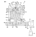
図3は、操舵部材10の正面図であり、図4は操舵部材10の要部の概略側面図である。図3および図4を参照して、操舵部材10は、傾斜状のステアリングシャフト50の上端に同伴回転可能に連結されている。操舵部材10は、上記ノブ51を回転可能に支持するホイール52と、ホイール52をステアリングシャフト50の上端に連結する複数のスポーク53とを有している。
FIG. 3 is a front view of the steering
また、上記ノブ51は、操舵部材10が操舵中立位置にあるときに、ホイール52の左部に位置するように配置されている。通例、運転者は、ノブ51を握って、操舵部材10を回転操作する。ノブ51は、操舵部材10の中心軸線C2(ステアリングシャフト50の中心軸線に一致)に平行なノブ中心C3の回りに回転可能とされている。
操舵部材10のホイール52は、スポーク53と連結された環状の芯金54と、芯金54を覆う例えば合成樹脂製のカバー55とを有している。芯金54には、上記ノブ中心C3に一致する中心軸線を有するノブ支持部としてのノブ支軸56が固定されている。
Further, the
The
ノブ51は、例えば下向きの筒状等の中空形状をなしている。すなわち、ノブ51は、筒状部57と、筒状部57の上端を閉塞する端壁58とを有している。ノブ51の内部には、上記ノブ反力アクチュエータ12が収容されている。
ノブ支軸56は、ノブ51の重心位置Pよりも高位に配置される部分を含んでいる。すなわち、ノブ支軸56の他端56bが、重心位置Pよりも高位に配置される部分に相当する。
The
The
ノブ反力アクチュエータ12は、ノブ支軸56の外周に固定されたステータ59と、ステータ59を取り囲み、ノブ51の内周51a(筒状部57の内周)に固定されたロータ60とを備えている。
ノブ支軸56は一端56aに大径のベース61を有し、そのベース61は、ホイール52の芯金54に固定されている。ノブ支軸56の小径の他端56bは、軸受62を介して、ノブ51を回転可能に支持している。
The knob
The
軸受62は、ノブ51の端壁58に設けられた軸受保持部63に保持されている。軸受62の外輪64は、軸受保持部63の一端の位置決め段部65に当接することにより、ノブ51に対する軸方向移動が規制されている。一方、軸受62の内輪66は、ノブ支軸56の他端56bの位置決め段部67に当接することにより、ノブ支軸56に対する軸方向移動が規制されている。これにより、ノブ51が、ノブ支軸56の一端56a側へ移動することが規制されている。
The
ノブ51の端壁58には、ノブ支軸56の他端56bの端面と対向する凹部68が設けられている。その凹部68の底に固定された可動部69と、ノブ支軸56の他端56bの端面に固定され、上記可動部69に対向する固定部70とによって、ノブ中心C3を中心とするノブ51の回転位置(ノブ回転角θN )を検出するノブ回転角検出手段としてのノブ回転角センサ71が構成されている。ノブ回転角センサ71としては、可動部69および固定部70の間の相対回転量を検出する例えばロータリエンコーダを用いることができる。
The
操舵部材10のホイール52の芯金54には、ノブ中心C3を中心とする案内筒72が固定されている。ノブ51の筒状部57の内周が、案内筒72の外周に回転可能に嵌合している。その案内筒72の外周には、周溝からなる案内溝73が形成されており、ノブ51の筒状部57に貫通固定されたピン74が、案内溝73に係合している。ピン74は案内溝73に沿って案内筒72の周方向に回転可能である。また、ピン74はノブ51が案内筒72から離脱することを防止する抜け止めピンとしても機能している。
A
また、ノブ51の内部には、運転者がノブ51を把持したことを検出する把持検出手段として、例えば静電センサからなる把持センサ75が配置されている。運転者がノブ51を把持すると、静電容量の変化に基づいて把持センサ75がECU100へ信号を出力する。ノブ回転角センサ71および把持センサ75の信号線や電動モータからなるノブ反力アクチュエータ12の電源線は、公知のスリップリング等を用いて、ノブ51外へ導出されている。
In addition, a
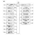
図5はフォークリフト1の主たる電気的構成を示すブロック図である。図5を参照して、ECU100には、操舵部材10のホイール回転角θH を検出するためのホイール回転角センサ14、転舵輪としての後輪6の転舵角θW を検出するための転舵角センサ15、積載部としてのフォーク27の積載荷重Wを検出するための荷重検出手段としての荷重センサ34、積載部としてのフォーク27の高さである積載部高さHを検出するための積載部高さ検出手段としてのストロークセンサ45、ノブ中心C3周りのノブ回転角θN を検出するノブ回転角センサ71、ノブ51の把持を検出する把持センサ75、車速Vを検出するための車速センサ76、昇降操作レバー36の位置を検出するための昇降操作レバー位置センサ77、チルト操作レバー37の位置を検出するためのチルト操作レバー位置センサ78、および前進/後進切替レバー38の切替に応じて作動する前進/後進切替スイッチ79のそれぞれから信号が入力されるようになっている。
FIG. 5 is a block diagram showing the main electrical configuration of the
また、ECU100から、転舵アクチュエータ11、ノブ反力アクチュエータ12、ホイール反力アクチュエータ13、油圧ポンプ8からリフトシリンダ31への作動油の供給を制御する電磁式の比例制御弁からなる昇降用制御弁80、油圧ポンプ8からチルトシリンダ28への作動油の供給を制御する電磁式の比例制御弁からなるチルト用制御弁81、前進クラッチを係合/離脱させるための油圧シリンダに作動油の供給を制御する電磁式比例制御弁からなる前進クラッチ用制御弁82、および後進クラッチを係合/離脱させるための油圧シリンダに作動油の供給を制御する電磁式比例制御弁からなる後進クラッチ用制御弁83のそれぞれに信号が出力されるようになっている。
The
ECU100は種々の制御を実行する。例えば、ECU100は、昇降操作レバー位置センサ77から入力された昇降操作レバー36の位置に応じて、油圧ポンプ8からリフトシリンダ31への作動油の供給を制御する昇降用制御弁80に制御信号を出力する。
また、ECU100は、チルト操作レバー位置センサ78から入力されたチルト操作レバー37の位置に応じて、油圧ポンプ8からチルトシリンダ28への作動油の供給を制御するチルト用制御弁81に制御信号を出力する。
The
Further, the
また、ECU100は、前進/後進切替スイッチ79が前進へ切り替えられることに応じて前進クラッチ用制御弁82に制御信号を出力し、前進クラッチを作動させるための油圧シリンダに、油圧ポンプ8からの作動油が供給されるようにする。
また、ECU100は、前進/後進切替スイッチ79が後進へ切り替えられることに応じて後進クラッチ用制御弁83に制御信号を出力し、後進クラッチを作動させるための油圧シリンダに、油圧ポンプ8からの作動油が供給されるようにする。
Further, the
Further, the
また、ECU100は、ノブ中心C3周りのノブ51の位置に応じた反力をノブ51に与えるためのトルクをノブ反力アクチュエータ12によって発生させるべく、ノブ回転角センサ71から入力されたノブ回転角θN に基づいて、ノブ反力アクチュエータ12を駆動制御する(すなわち、ノブ反力アクチュエータ12の反力制御を実行する)場合がある。
In addition, the
また、ECU100は、操舵部材10のホイール回転角θH に応じた操舵反力を操舵部材10のホイール52に与えるためのトルクをホイール反力アクチュエータ13によって発生させるべく、ホイール回転角センサ14から入力されたホイール回転角θH に基づいて、ホイール反力アクチュエータ13を駆動制御する(すなわち、ホイール反力アクチュエータ13を反力制御を実行する)場合がある。
Further, the
具体的には、図6に示すように、ECU100は、目標ホイール反力TH * を設定する目標ホイール反力設定部85と、目標ホイール反力TH * を補正する目標ホイール反力補正部86と、目標ホイール反力設定部85および目標ホイール反力補正部86の間に介在する第1の切替部87と、第1の補正係数算出部88と、把持センサ75からの把持信号eを入力する把持信号受信部89と、把持信号受信部89からの信号を入力し、入力してからき経過時間を計測するタイマー90と、目標ノブ反力TN * を設定する目標ノブ反力設定部91と、目標ノブ反力TN * を補正する目標ノブ反力補正部92と、目標ノブ反力設定部91および目標ノブ反力補正部92の間に介在する第2の切替部93と、第2の補正係数算出部94と、ホイール反力アクチュエータ13を駆動するための駆動回路95と、ノブ反力アクチュエータ12を駆動するための駆動回路96とを備えている。
Specifically, as shown in FIG. 6,
また、ECU100は、操舵部材10のホイール回転角θH およびホイール反力TH の関係を、ホイール回転角−ホイール反力マップM1として記憶しており、ノブ回転角θN およびノブ反力TN の関係をノブ回転角−ノブ反力マップM2として記憶している。
目標ホイール反力設定部85は、入力したホイール回転角θH に基づいて、ホイール回転角−ホイール反力マップM1を用いて、目標ホイール反力TH * を設定し、第1の切替部87に出力する。目標ノブ反力設計部91は、入力したノブ回転角θN に基づいて、ノブ回転角−ノブ反力マップM2を用いて、目標ノブ反力TN * を設定し、第2の切替部93に出力する。
Moreover,
Target wheel reaction
把持信号受信部89は、把持センサ75からの把持信号eの入力に応じて、第1の切替部87および第2の切替部93にそれぞれ切替信号e1を出力する。
第1の切替部87は、切替信号e1の入力がないときは、目標ホイール反力TH * を目標ホイール反力補正部86に出力する。また、第1の切替部87は、切替信号e1を入力すると、目標ホイール反力補正部86を迂回して、目標ホイール反力TH * を駆動回路95に直接出力する。
The grip
The
第2の切替部93は、切替信号e1の入力がないときは、目標ノブ反力TN * を目標ノブ反力補正部92に出力する。また、第2の切替部93は、切替信号e1を入力すると、目標ノブ反力補正部92を迂回して、目標ノブ反力TN * を駆動回路96に直接出力する。
本実施の形態では、把持センサ75によってノブ51の把持が検出されてからの所定期間を、ホイール反力アクチュエータ13のみによる反力付与からノブ反力アクチュエータ12のみによる反力付与へ徐々に移行するための移行期間としている。
The
In the present embodiment, the predetermined period after the
把持信号受信部89は、把持センサ75からの把持信号eの入力に応じて、タイマー90にタイマー開始指令信号e2を出力する。タイマー90は、タイマー開始指令信号e2の入力に応じて、上記移行期間の計時を開始する。また、タイマー90は、計測時間に相当するカウント値Cを第1の補正係数算出部88および第2の補正係数算出部94に出力する。
The grip
第1の補正係数算出部88は、第1の補正係数k1を下記式(1)に基づいて算出し、算出した第1の補正係数k1を目標ホイール反力補正部86に出力する。
k1=(CMAX −C)/CMAX …(1)
ここで、CMAX は最大カウント値であり、タイマー90のカンウトアップ値である。
第1の補正係数k1は、計測時間の増大とともに1から減少し、タイマー90のカウントアップ時(すなわち、ホイール反力付与からノブ反力付与への移行期間の終了時)に、0となる。
The first correction coefficient calculation unit 88 calculates the first correction coefficient k1 based on the following formula (1), and outputs the calculated first correction coefficient k1 to the target wheel reaction
k1 = (C MAX −C) / C MAX (1)
Here, C MAX is a maximum count value and is a count-up value of the
The first correction coefficient k1 decreases from 1 as the measurement time increases, and becomes 0 when the
目標ホイール反力補正部86は、第1の切替部87から入力した目標ホイール反力TH * に、第1の補正係数算出部88から入力した第1の補正係数k1を乗算して、目標ホイール反力TH * を補正する。すなわち、乗算値TH * ・k1を求め、この乗算値TH * ・k1を新たな目標ホイール反力TH * とする。
第2の補正係数算出部94は、第2の補正係数k2を下記式(2)に基づいて算出し、算出した第2の補正係数k2を目標ノブ反力補正部92に出力する。
The target wheel reaction
The second correction
k2=C/CMAX …(2)
第2の補正係数k2は、計測時間の増大とともに0から増大し、タイマー90のカウントアップ時(すなわち、ホイール反力付与からノブ反力付与への移行期間の終了時)に、1となる。
目標ノブ反力補正部92は、第2の切替部93から入力した目標ノブ反力TN * に、第2の補正係数算出部94から入力した第2の補正係数k2を乗算して、目標ノブ反力TN * を補正する。すなわち、乗算値TN * ・k2を求め、これを新たな目標ノブ反力TN * とする。
k2 = C / C MAX (2)
The second correction coefficient k2 increases from 0 as the measurement time increases, and becomes 1 when the
The target knob reaction
図7はECU100の主たる動作を示すフローチャートである。図7を参照して、ECU100は、まず、ステップS1において、タイマー90のカウント値Cを0にクリアする。次いで、ステップS2において、把持センサ75からの把持信号eの入力があるか否かを判定し、把持信号eの入力がない場合(ステップS1においてNOの場合)には、ノブ51が把持されていないので、ステップS9に進み、ステップS2の把持信号eの入力がないこと(ステップS2においてNOであること)を確認しながら、通常のホイール反力アクチュエータ13の反力制御を実行する(ステップS1,S2およびS9)。
FIG. 7 is a flowchart showing the main operation of the
ステップS2において、把持信号S1の入力があると判定された場合(ステップS2にてYESの場合)には、タイマー90のカンウトをスタートし(ステップS3)、ホイール反力付与からノブ反力付与に徐々に切り替える移行期間を設定する。その移行期間の間、ステップS4〜S6のステップを繰り返し、ステップS4の移行制御を実行する。
ステップS5では、タイマー90のカウント値Cを1増加させ、ステップS6では、カウント値Cがカウントアップ値CMAX 以下(移行期間が終了していない)か否かが判定される。
If it is determined in step S2 that the grip signal S1 is input (YES in step S2), the count of the
In step S5, the count value C of the
ステップS6でNOと判定され移行期間が終了すると、ステップS7に進み、把持信号eの入力が継続されているか否かを判定し、把持信号eの入力が継続されている場合(ステップS7においてYESの場合)には、引き続きノブ反力アクチュエータ12の反力制御を実行する(ステップS8)。
ステップS7,S8を繰り返しているうちに、把持信号eの入力がなくなった場合(ステップS7においてNOの場合)には、ステップS1に戻る。
When NO is determined in step S6 and the transition period ends, the process proceeds to step S7, where it is determined whether or not the input of the grip signal e is continued. If the input of the grip signal e is continued (YES in step S7). In this case, the reaction force control of the knob
If the grip signal e is no longer input while repeating steps S7 and S8 (NO in step S7), the process returns to step S1.
図8は移行制御の流れを示している。図8を参照して、ステップS41において、ノブ回転角センサ71からの信号に基づいて得られたノブ回転角θN を読み込み、ステップS42において、目標ノブ反力設定部91が、上記読み込まれたノブ回転角θN に基づくノブ反力TN をマップM2を用いて求め、求められたノブ反力TN を目標ノブ反力TN * に設定する。
FIG. 8 shows the flow of transition control. Referring to FIG. 8, in step S41, the knob rotation angle θ N obtained based on the signal from the knob
次いで、ステップS43では、第2の補正係数算出部94が、タイマー90から入力したカンウト値Cに基づいて、上記式(2)を用いて、第2の補正係数k2を算出する。
次いで、ステップS44では、ステップS42で設定された目標ノブ反力TN * に、ステップS43で算出された第2の補正係数k2を乗算して、乗算値TN * ・k2を求め、この乗算値TN * ・k2を新たな目標ノブ反力TN * に設定する。
Next, in step S43, the second correction
Next, in step S44, the target knob reaction force T N * set in step S42 is multiplied by the second correction coefficient k2 calculated in step S43 to obtain a multiplication value T N * · k2, and this multiplication The value T N * · k2 is set to a new target knob reaction force T N * .
次いで、ステップS45では、目標ノブ反力TN * に基づいて、ノブ反力アクチュエータ12を駆動制御する(すなわち、ノブ反力アクチュエータ12の反力制御を実行する)。
次いで、ステップS46において、ホイール回転角センサ14からの信号に基づいて得られたホイール回転角θH を読み込み、ステップS47において、上記読み込まれたホイール回転角θH に基づくホイール反力TH (操舵反力に相当)を、ホイール回転角−ホイール反力マップM1を用いて求め、求められたホイール反力TH を目標ホイール反力TH * に設定する。
Next, in step S45, the knob
Then, in step S46, reads the wheel rotation angle theta H obtained based on a signal from the wheel
次いで、ステップS48では、第1の補正係数算出部88が、タイマー90から入力したカンウト値Cに基づいて、上記式(1)を用いて、第1の補正係数k1を算出する。
次いで、ステップS49では、ステップS47で設定された目標ホイール反力TH * に、ステップS48で算出された第1の補正係数k1を乗算して、乗算値TH * ・k1を求め、この乗算値TH * ・k1を新たな目標ノブ反力TH * に設定する。
Next, in step S <b> 48, the first correction coefficient calculation unit 88 calculates the first correction coefficient k <b> 1 using the above formula (1) based on the count value C input from the
Next, in step S49, the target wheel reaction force T H * set in step S47 is multiplied by the first correction coefficient k1 calculated in step S48 to obtain a multiplication value T H * · k1. The value T H * · k1 is set to a new target knob reaction force T H * .
次いで、ステップS50では、決定された目標ホイール反力TH * に基づいて、ホイール反力アクチュエータ13を駆動制御する(すなわちホイール反力アクチュエータ13の反力制御を実行する)。ステップS50の終了後、図7のステップS7に戻る。ステップS41〜ステップS50の移行制御が移行期間の間繰り返されることになる。
本実施の形態によれば、ノブ51を持って操舵部材10を操作するとき、操舵部材10のホイール52の回転に応じてノブ51がノブ中心C3周りに回転(自転)する。そのノブ51の回転(自転)に対してノブ反力アクチュエータ12が反力を与えるので、ノブ51を用いた操舵に対して適切な操舵反力を付与することができる。
Next, in step S50, the wheel
According to the present embodiment, when the steering
特に、運転者が操舵部材10のホイール52からノブ51へ持ち替えて操舵するときに、ノブ反力を経時的に増大させ且つホイール反力を経時的に減少させる移行期間を設けているので、ホイール反力の付与からノブ反力の付与へとスムーズに切り替えることができる。したがって、上記持ち替えに際して運転者が操舵に違和感を感じることがない。すなわち、従来の操舵フィーリングに慣れている運転者にも違和感を与えることが少なく、運転者に操作し易くすることができる。
In particular, when the driver changes the
また、移行期間では、目標ホイール反力TH * が、タイマー90の計測時間(カウント値C)の増大に応じて減少する第1の補正係数k1を乗じて補正されることにより漸減する一方、目標ノブ反力TN * が、タイマー90の計測時間(カウント値C)の増大に応じて増大する第2の補正係数k2を乗じて補正されることにより漸増する。したがって、この移行期間を経てホイール反力の付与からノブ反力の付与へとスムーズに切り替えることができる。
Further, in the transition period, the target wheel reaction force TH * is gradually reduced by being corrected by multiplying by the first correction coefficient k1 that decreases as the measurement time (count value C) of the
具体的には、タイマー90の計測時間が上記所定時間に達したときに、すなわち、タイマー90のカウント値Cがカンウトアップ値CMAX に達したときに、第1の補正係数k1がゼロになり、第2の補正係数k2が1になることにより、移行期間の終了時点で、ホイール反力の付与からノブ反力の付与へと完全に切り替えることができる。
また、ノブ51を回転可能に支持するノブ支軸56が、ノブ51の重心位置Pよりも高位に配置される部分として、他端56bを有しているので、ノブ支軸56に対してノブ51が傾斜することを防止できる。したがって、ノブ反力アクチュエータ12による反力以外の反力(摩擦抵抗等による反力)の発生を防止することができ、その結果、良好な操舵が可能となる。
More specifically, when the time measured by the
Further, the
さらに、運転者がノブ51を握って操舵部材10を回転させるとき、ノブ51は操舵部材10のホイール52に対して、ホイール52の回転方向とは逆方向に、ホイール52の回転角(ホイール回転角θH )と等しい角度でノブ中心C3周りに回転(自転)することになる。本実施の形態では、ノブ中心C3周りのノブ51の回転角を検出するノブ回転角センサ71を備え、ノブ回転角センサ71により検出されたノブ中心C3周りのノブ51のノブ回転角θN に応じて、ノブ反力アクチュエータ12による反力を制御する。これにより、ノブ回転角θN に応じた反力を、実際の路面からの反力に相当する反力として、ノブ51を介して運転者に与えることができる。
Further, when the driver holds the
なお、本発明は上記実施の形態に限定されるものではなく、例えば、上記の実施の形態では、第1の補正係数算出部88および第2の補正係数算出部94が、それぞれ演算式を用いて第1の補正係数k1および第2の補正係数を演算していたが、これに代えて、図9に示すような、予め記憶した各補正係数の時間マップを用いて、各補正係数を求めるようにしてもよい。
The present invention is not limited to the above embodiment. For example, in the above embodiment, the first correction coefficient calculation unit 88 and the second correction
また、把持センサ75として、図4の静電センサに代えて、ノブ支軸56の曲げを検出する歪みセンサからなる把持センサや、ノブ51の表面に負荷される押圧力を検出する圧力センサからなる把持センサや、押しボタンスイッチからなる把持センサを用いるようにしてもよい。また、これらのタイプの異なる把持センサを2つ以上組み合わせて用いるようにしてもよい。
Further, as the
また、図6のノブ回転角−ノブ反力マップM2をノブ回転角速度θN ’および車速Vの少なくとも一方に基づいて補正するようにしてもよい。具体的には、ノブ位置センサ71から取得したノブ回転角θN を微分して得られたノブ回転角速度θN ’が小さいほど、また、車速センサ76から取得した車速Vが小さいほど、ノブ反力TN が小さくなるように、ノブ回転角−ノブ反力マップを補正する場合がある。この場合、ノブ51の操作性を向上することができる。
Further, the knob rotation angle-knob reaction force map M2 in FIG. 6 may be corrected based on at least one of the knob rotation angular velocity θ N ′ and the vehicle speed V. Specifically, as the knob rotation angular velocity θ N ′ obtained by differentiating the knob rotation angle θ N obtained from the
逆に、ノブ回転角センサ71から取得したノブ回転角速度θN ’を微分して得られたノブ回転角速度θN ’が大きいほど、また、車速センサ76から取得した車速Vが大きいほど、ノブ反力TN が大きくなるように、ノブ回転角−ノブ反力マップそ2を補正する場合がある。この場合、フォークリフト1の走行の安全性を向上することができる。
また、図6のホイール回転角−ホイール反力マップM1をホイール回転角速度θH ’(操舵速度に相当)および車速Vの少なくとも一方に基づいて補正するようにしてもよい。具体的には、ホイール回転角センサ14から取得したホイール回転角θH を微分して得られたホイール回転角速度θH ’が小さいほど、また、車速センサ76から取得した車速Vが小さいほど、ホイール反力TH が小さくなるように、ホイール回転角−ホイール反力マップM1を補正する場合がある。この場合、操舵部材10の操作性を向上することができる。
Conversely, the greater the knob rotation angular velocity θ N ′ obtained by differentiating the knob rotation angular velocity θ N ′ obtained from the knob
Further, the wheel rotation angle-wheel reaction force map M1 of FIG. 6 may be corrected based on at least one of the wheel rotation angular velocity θ H ′ (corresponding to the steering speed) and the vehicle speed V. Specifically, the smaller the wheel rotation angular velocity θ H ′ obtained by differentiating the wheel rotation angle θ H acquired from the wheel
逆に、ホイール回転角センサ14から取得したホイール回転角θH を微分して得られたホイール回転角速度θH ’(操舵速度)が大きいほど、また、車速センサ76から取得した車速Vが大きいほど、ホイール反力TH が大きくなるように、ホイール回転角−ホイール反力マップM1を補正する場合がある。この場合、フォークリフト1の走行の安全性を向上することができる。
Conversely, the greater the wheel rotation angular velocity θ H ′ (steering speed) obtained by differentiating the wheel rotation angle θ H acquired from the wheel
また、上記実施の形態では、車両が荷役車両としてのフォークリフトである例に則して説明したが、本発明はこれに限られるものではなく、ノブ付きのハンドル(操舵部材)を有する車両(例えば障害者用の車両等)であれば、本発明を適用可能である。その他、本発明の特許請求の範囲で種々の変更を施すことができる。 In the above-described embodiment, the example in which the vehicle is a forklift as a cargo handling vehicle has been described. However, the present invention is not limited to this, and a vehicle having a handle (steering member) with a knob (for example, The present invention can be applied to a vehicle for a disabled person or the like. In addition, various modifications can be made within the scope of the claims of the present invention.
1…フォークリフト(荷役車両)、2…車体、3…荷役装置、6…後輪(転舵輪)、9…車両用操舵装置、10…操舵部材、11…転舵アクチュエータ、12…ノブ反力アクチュエータ、13…ホイール反力アクチュエータ、14…ホイール回転角センサ、51…ノブ、52…ホイール、56…ノブ支軸、56b…他端(重心位置よりも上位に配置される部分)、71…ノブ回転角センサ、75…把持センサ(把持検出手段)、85…目標ホイール反力設定部、86…目標ホイール反力補正部、87…第1の切替部、88…第1の補正係数算出部、89…把持信号受信部、90…タイマー、91…目標ノブ反力設定部、92…目標ノブ反力補正部、93…第2の切替部、94…第2の補正係数算出部、95,96…駆動回路、100…ECU(制御手段)、A1…転舵機構、C…カウント値、CMAX …カウントアップ値、C2…ホイール中心、C3…ノブ中心、e…把持信号、e1…切替信号、e2…タイマー開始指令信号、θH …ホイール回転角、θN …ノブ回転角、P…重心位置、TH …ホイール反力、TH * …目標ホイール反力、TN …ノブ反力、TN * …目標ノブ反力
DESCRIPTION OF
Claims (4)
上記ホイールの回転にホイール反力を付与するホイール反力アクチュエータと、
上記ノブの回転にノブ反力を付与するノブ反力アクチュエータと、
上記ノブが把持されたことを検出する把持検出手段と、
上記ノブ反力アクチュエータおよび上記ホイール反力アクチュエータを制御する制御手段と、を備え、
上記制御手段は、上記把持検出手段によって上記ノブの把持が検出されてからの所定期間をホイール反力アクチュエータのみによる反力付与からノブ反力アクチュエータのみによる反力付与へ移行するための移行期間に設定しており、その移行期間において、上記ノブ反力を経時的に増大させ且つ上記ホイール反力を経時的に減少させるようにしている車両用操舵装置。 A knob for rotating a wheel of a steering member, the knob having a knob center, and supported by the wheel so as to be rotatable around the knob center;
A wheel reaction force actuator that applies a wheel reaction force to the rotation of the wheel;
A knob reaction force actuator for applying a knob reaction force to the rotation of the knob;
Grip detection means for detecting that the knob is gripped;
Control means for controlling the knob reaction force actuator and the wheel reaction force actuator,
The control means is a transition period for transitioning from a reaction force applied only by the wheel reaction force actuator to a reaction force application only by the knob reaction force actuator for a predetermined period after the grip detection of the knob is detected by the grip detection means. A steering apparatus for a vehicle that is set, and during the transition period, the knob reaction force is increased with time and the wheel reaction force is decreased with time.
上記制御手段は、
上記ホイール回転角検出手段によって検出されたホイール回転角に基づいて目標ホイール反力を設定する目標ホイール反力設定部と、
上記ノブ回転角検出手段によって検出されたノブ回転角に基づいて目標ノブ反力を設定する目標ノブ反力設定部と、
上記把持検出手段による把持の検出からの経過時間を計測するタイマーと、
上記移行期間に、上記目標ホイール反力を、上記タイマーの計測時間の増大に応じて減少する第1の補正係数を乗じて補正する目標ホイール反力補正部と、
上記移行期間に、上記目標ノブ反力を、上記タイマーの計測時間の増大に応じて増加する第2の補正係数を乗じて補正する目標ノブ反力補正部と、を含む車両用操舵装置。 The knob rotation angle detection means for detecting the knob rotation angle around the knob center, and the wheel rotation angle detection means for detecting the wheel rotation angle around the wheel center according to claim 1,
The control means includes
A target wheel reaction force setting unit for setting a target wheel reaction force based on the wheel rotation angle detected by the wheel rotation angle detection means;
A target knob reaction force setting unit for setting a target knob reaction force based on the knob rotation angle detected by the knob rotation angle detection means;
A timer for measuring an elapsed time from detection of gripping by the gripping detection means;
A target wheel reaction force correction unit that corrects the target wheel reaction force by multiplying by a first correction coefficient that decreases as the measurement time of the timer increases during the transition period;
A vehicle steering apparatus including a target knob reaction force correction unit that corrects the target knob reaction force by a second correction coefficient that increases with an increase in the measurement time of the timer during the transition period.
上記ノブ支軸は、上記ノブの重心位置よりも高位に配置される部分を含む車両用操舵装置。 In Claim 1 or 2, comprising a knob support shaft supported by the wheel and rotatably supporting the knob,
The vehicle steering apparatus, wherein the knob support shaft includes a portion disposed higher than a center of gravity of the knob.
Priority Applications (4)
| Application Number | Priority Date | Filing Date | Title |
|---|---|---|---|
| JP2010230669A JP5557030B2 (en) | 2010-10-13 | 2010-10-13 | Vehicle steering system |
| EP11184630.9A EP2441647B1 (en) | 2010-10-13 | 2011-10-11 | Motor vehicle steering system |
| US13/270,801 US8467939B2 (en) | 2010-10-13 | 2011-10-11 | Motor vehicle steering system |
| CN201110316255.5A CN102442343B (en) | 2010-10-13 | 2011-10-12 | Vehicle steering apparatus |
Applications Claiming Priority (1)
| Application Number | Priority Date | Filing Date | Title |
|---|---|---|---|
| JP2010230669A JP5557030B2 (en) | 2010-10-13 | 2010-10-13 | Vehicle steering system |
Publications (2)
| Publication Number | Publication Date |
|---|---|
| JP2012081896A JP2012081896A (en) | 2012-04-26 |
| JP5557030B2 true JP5557030B2 (en) | 2014-07-23 |
Family
ID=44862527
Family Applications (1)
| Application Number | Title | Priority Date | Filing Date |
|---|---|---|---|
| JP2010230669A Expired - Fee Related JP5557030B2 (en) | 2010-10-13 | 2010-10-13 | Vehicle steering system |
Country Status (4)
| Country | Link |
|---|---|
| US (1) | US8467939B2 (en) |
| EP (1) | EP2441647B1 (en) |
| JP (1) | JP5557030B2 (en) |
| CN (1) | CN102442343B (en) |
Families Citing this family (8)
| Publication number | Priority date | Publication date | Assignee | Title |
|---|---|---|---|---|
| JP5807778B2 (en) * | 2011-09-15 | 2015-11-10 | 株式会社ジェイテクト | Steering device for cargo handling vehicle |
| DE102011116645A1 (en) * | 2011-10-21 | 2013-04-25 | Robert Bosch Gmbh | Method for continuously measuring lift height of fork carriage of forklift truck for lifting loads, involves detecting twisting angle of deflection roller by measuring device, and determining lift height based on detected twisting angle |
| DE102016216796B4 (en) * | 2015-09-08 | 2023-10-26 | Toyota Jidosha Kabushiki Kaisha | STEERING REACTION POWER CONTROL DEVICE FOR VEHICLE |
| JP6780405B2 (en) * | 2016-09-21 | 2020-11-04 | 株式会社ジェイテクト | Steering control device |
| JP6351801B2 (en) * | 2017-06-26 | 2018-07-04 | 住友理工株式会社 | Gripping state detection sensor |
| JP2019202620A (en) * | 2018-05-23 | 2019-11-28 | 有限会社マーキュリー | Assist grip |
| JP6393858B1 (en) * | 2018-06-12 | 2018-09-19 | 株式会社ショーワ | Rudder angle regulating device |
| CN115348933B (en) * | 2021-03-12 | 2024-02-27 | 日本精工株式会社 | Detection device, detection method, and program for end position of steering device |
Family Cites Families (23)
| Publication number | Priority date | Publication date | Assignee | Title |
|---|---|---|---|---|
| JPS6337381A (en) | 1986-08-01 | 1988-02-18 | 松下電器産業株式会社 | Document editing paper total display and apparatus used therefor |
| JPS6337381U (en) * | 1986-08-28 | 1988-03-10 | ||
| US5032999A (en) * | 1989-11-01 | 1991-07-16 | Yale Materials Handling Corporation | Motion sensor useful for power assisted steering systems |
| JPH05105100A (en) * | 1991-09-27 | 1993-04-27 | Honda Motor Co Ltd | Vehicle steering system |
| SE502702C2 (en) * | 1991-12-18 | 1995-12-11 | Abb Truck Ab | Power steering system for vehicles |
| JP3480470B2 (en) | 1993-05-31 | 2003-12-22 | 株式会社ニコン | Progressive multifocal lens |
| JPH07232647A (en) * | 1993-12-27 | 1995-09-05 | Toyota Autom Loom Works Ltd | Steering torque detecting device in power steering device |
| JPH11115778A (en) * | 1997-10-14 | 1999-04-27 | Nippon Yusoki Co Ltd | Steering device |
| JP4810774B2 (en) * | 2001-08-02 | 2011-11-09 | 株式会社豊田自動織機 | Steering device and vehicle |
| JP3991632B2 (en) * | 2001-08-02 | 2007-10-17 | 株式会社豊田自動織機 | Steering wheel position correction device for vehicle and vehicle |
| CA2396349C (en) | 2001-08-02 | 2006-01-24 | Kabushiki Kaisha Toyota Jidoshokki | Steering wheel position compensating apparatus in steering apparatus |
| JP3883107B2 (en) * | 2001-11-30 | 2007-02-21 | 本田技研工業株式会社 | Vehicle steering device |
| JP4061105B2 (en) * | 2002-03-29 | 2008-03-12 | アルプス電気株式会社 | Haptic device |
| JP2005028510A (en) * | 2003-07-14 | 2005-02-03 | Alps Electric Co Ltd | Inner force sense imparting type input device |
| JP4400170B2 (en) * | 2003-10-10 | 2010-01-20 | トヨタ自動車株式会社 | Mobile control device |
| DE102004040975A1 (en) * | 2004-08-24 | 2006-03-02 | Linde Ag | Steering wheel for mobile work machine e.g. industrial truck, has operating units, sensor unit and feedback unit integrated in knob of steering wheel, where sensor unit detects presence of operating person in mobile work machine |
| JP2006251845A (en) * | 2005-03-08 | 2006-09-21 | Alps Electric Co Ltd | Inner force sense applying type input device |
| JP2007253640A (en) * | 2006-03-20 | 2007-10-04 | Honda Motor Co Ltd | Steering device and steering control method |
| CN201040540Y (en) * | 2007-04-02 | 2008-03-26 | 安徽合力股份有限公司 | Fork lift direction machine with angle adjusting mechanism |
| CN201023519Y (en) * | 2007-04-23 | 2008-02-20 | 印辉 | Device for automatically adjusting fork lift turning pipe column angle |
| JP5386103B2 (en) * | 2008-04-17 | 2014-01-15 | ニチユ三菱フォークリフト株式会社 | Vehicle steering control device |
| JP5257683B2 (en) * | 2009-01-20 | 2013-08-07 | 株式会社ジェイテクト | Vehicle steering system |
| JP5708976B2 (en) * | 2010-06-16 | 2015-04-30 | 株式会社ジェイテクト | Vehicle steering system |
-
2010
- 2010-10-13 JP JP2010230669A patent/JP5557030B2/en not_active Expired - Fee Related
-
2011
- 2011-10-11 EP EP11184630.9A patent/EP2441647B1/en not_active Not-in-force
- 2011-10-11 US US13/270,801 patent/US8467939B2/en active Active
- 2011-10-12 CN CN201110316255.5A patent/CN102442343B/en not_active Expired - Fee Related
Also Published As
| Publication number | Publication date |
|---|---|
| CN102442343B (en) | 2016-01-13 |
| EP2441647A3 (en) | 2012-11-28 |
| US20120095648A1 (en) | 2012-04-19 |
| US8467939B2 (en) | 2013-06-18 |
| EP2441647A2 (en) | 2012-04-18 |
| JP2012081896A (en) | 2012-04-26 |
| CN102442343A (en) | 2012-05-09 |
| EP2441647B1 (en) | 2014-04-23 |
Similar Documents
| Publication | Publication Date | Title |
|---|---|---|
| JP5557030B2 (en) | Vehicle steering system | |
| JP5708976B2 (en) | Vehicle steering system | |
| JP5645069B2 (en) | Vehicle steering system | |
| CN113302146B (en) | Forklift truck | |
| CN110857134B (en) | Speed change control system of manpower-driven vehicle | |
| JP5392550B2 (en) | Vehicle steering system | |
| CN110884608B (en) | Control device for human-powered vehicle | |
| JP5067261B2 (en) | Operating device | |
| JP5305085B2 (en) | Vehicle steering system | |
| JP2010254237A (en) | Steering device for vehicle | |
| JP5403334B2 (en) | Vehicle steering system | |
| JP5569735B2 (en) | Vehicle steering system | |
| JP5354264B2 (en) | Vehicle steering system | |
| JP2014185005A (en) | Cargo-handling vehicle | |
| JP2010132379A (en) | Cargo handling vehicle | |
| JP5278755B2 (en) | Vehicle steering system | |
| JP2012076651A (en) | Vehicle steering device | |
| JP5464999B2 (en) | Reach forklift | |
| JP2010132379A5 (en) |
Legal Events
| Date | Code | Title | Description |
|---|---|---|---|
| A621 | Written request for application examination |
Free format text: JAPANESE INTERMEDIATE CODE: A621 Effective date: 20130924 |
|
| A977 | Report on retrieval |
Free format text: JAPANESE INTERMEDIATE CODE: A971007 Effective date: 20140313 |
|
| TRDD | Decision of grant or rejection written | ||
| A01 | Written decision to grant a patent or to grant a registration (utility model) |
Free format text: JAPANESE INTERMEDIATE CODE: A01 Effective date: 20140508 |
|
| A61 | First payment of annual fees (during grant procedure) |
Free format text: JAPANESE INTERMEDIATE CODE: A61 Effective date: 20140521 |
|
| R150 | Certificate of patent or registration of utility model |
Ref document number: 5557030 Country of ref document: JP Free format text: JAPANESE INTERMEDIATE CODE: R150 |
|
| LAPS | Cancellation because of no payment of annual fees |