JP5305085B2 - Vehicle steering system - Google Patents
Vehicle steering system Download PDFInfo
- Publication number
- JP5305085B2 JP5305085B2 JP2008307768A JP2008307768A JP5305085B2 JP 5305085 B2 JP5305085 B2 JP 5305085B2 JP 2008307768 A JP2008307768 A JP 2008307768A JP 2008307768 A JP2008307768 A JP 2008307768A JP 5305085 B2 JP5305085 B2 JP 5305085B2
- Authority
- JP
- Japan
- Prior art keywords
- unit
- steering
- vehicle
- load
- cargo handling
- Prior art date
- Legal status (The legal status is an assumption and is not a legal conclusion. Google has not performed a legal analysis and makes no representation as to the accuracy of the status listed.)
- Expired - Fee Related
Links
Images


Description
本発明は荷役車両のための車両用操舵装置に関するものである。 The present invention relates to a vehicle steering apparatus for a cargo handling vehicle.
通例、荷役装置としてのフォークリフトでは、前輪が向きを固定した駆動輪とされ、後輪が転舵輪とされている。フォークリフト等の操舵装置は、ステアリングハンドル(操舵部材)の操舵に応じて、上記転舵輪としての後輪を転舵することにより、操舵を実行している。
また、フォークリフトでは、車体の前部に設けられた荷役装置のフォークに、重量物を積載する。このようにフォークに重量物を積載したときに、車両が前方へ倒れ込むことを防止する目的で、フォークリフトは、車体の後部に、カウンタウェイトと呼ばれる「重し」を搭載している。この種のフォークリフトが、カウンタウェイト式のフォークリフトである。
Usually, in a forklift as a cargo handling device, a front wheel is a driving wheel whose direction is fixed, and a rear wheel is a steered wheel. A steering device such as a forklift performs steering by turning a rear wheel as the steered wheel in accordance with steering of a steering handle (steering member).
Further, in the forklift, a heavy object is loaded on the fork of the cargo handling device provided at the front of the vehicle body. In order to prevent the vehicle from falling forward when a heavy object is loaded on the fork in this way, the forklift is equipped with a “weight” called a counterweight at the rear of the vehicle body. This type of forklift is a counterweight forklift.
一方、運転座席から距離を隔てた旋回軸線を中心として、具体的には、フットペダルの位置に配置された旋回軸線を中心として、運転座席を旋回させるようにしたフォークリフトが提案されている(例えば特許文献1を参照)。
カウンタウェイト式のフォークリフトにおいて、フォークに荷物を積載している積載時は、荷物の荷重が、前輪を支点として、後輪の接地荷重を低減させる方向にモーメントを生じさせている。このため、積載時において、前輪および後輪の接地荷重が、ほぼ均衡している。
しかし、フォークに荷物を積載していない空荷時は、荷物による上記モーメントが生じていないため、後輪の接地荷重が、前輪の接地荷重よりも格段に大きくなる。その結果、後輪を転舵するときに、後輪に転舵力(或いは転舵補助力)を与えるための操舵アクチュエータの負荷が格段に大きくなる。このため、操舵アクチュエータの寿命が短くなる。また、高負荷に耐え得る大型の操舵アクチュエータが必要とされる。
In a counterweight forklift, when a load is loaded on a fork, the load of the load generates a moment in a direction that reduces the ground load on the rear wheel with the front wheel as a fulcrum. For this reason, at the time of loading, the ground contact loads of the front wheels and the rear wheels are substantially balanced.
However, when no load is loaded on the fork, the above-mentioned moment is not generated by the load, and therefore the ground load on the rear wheel is significantly larger than the ground load on the front wheel. As a result, when the rear wheel is steered, the load on the steering actuator for applying the steered force (or the steering assist force) to the rear wheel is significantly increased. For this reason, the life of the steering actuator is shortened. In addition, a large steering actuator that can withstand a high load is required.
また、空荷時のフォークリフトは前後の重量バランスが悪いので、走行安定性にやや劣るという問題がある。
本発明は上記課題に鑑みてなされたものであり、空荷時の転舵負荷を軽減することにより耐久性に優れ、また車両の走行安定性にも寄与することができる車両用操舵装置を提供することを目的とする。
In addition, since the forklift in an unloaded state has a poor weight balance between the front and rear, there is a problem that the running stability is slightly inferior.
The present invention has been made in view of the above problems, and provides a vehicle steering apparatus that is excellent in durability and can contribute to running stability of the vehicle by reducing the steering load during empty load. The purpose is to do.
上記目的を達成するため、本発明は、車体(2)の前部に荷役装置(3)を備えるとともに車体の後部にカウンタウェイト(4)を備えた荷役車両(1)を操舵するための車両用操舵装置(9)において、操舵部材(24)と、操舵部材の操作に応じて転舵輪としての後輪(6)を転舵するための操舵力を発生する操舵アクチュエータ(25)と、少なくとも運転座席(10)を含み、上記車体によって車両の前後方向に沿うスライド方向(X1)にスライド可能に支持されたユニット(11)と、上記スライド方向に沿って上記ユニットを移動させるための駆動機構(12)と、上記荷役装置が受ける荷重を検出するための荷重センサ(80)と、上記荷重センサにより検出された荷重(W)が所定値(W1)以下のときに、上記ユニットを上記スライド方向前方にスライドさせるように、上記駆動機構を制御する制御部(13)とを備えたことを特徴とする。 In order to achieve the above object, the present invention provides a vehicle for steering a cargo handling vehicle (1) having a cargo handling device (3) at the front portion of the vehicle body (2) and a counterweight (4) at the rear portion of the vehicle body. A steering member (24), a steering actuator (25) for generating a steering force for turning a rear wheel (6) as a steered wheel in response to an operation of the steering member, A unit (11) including a driver seat (10) and supported by the vehicle body so as to be slidable in a sliding direction (X1) along the front-rear direction of the vehicle, and a drive mechanism for moving the unit along the sliding direction and (12), a load sensor (80) for detecting a load which the handling device receives, when the detected load (W) is below a predetermined value (W1) by the load sensor, said unit As to slide the slide forward, characterized by comprising control unit for controlling the drive mechanism (13).
本発明によれば、車両の後部にカウンタウェイトを備える荷役車両において、運転座席を含むユニットを前後にスライドさせることにより、車両の前後の重量バランスを調整することができる。これにより、例えば空荷時の後輪の接地荷重が過大になることを防止でき、その結果、空荷時に後輪を転舵するときの操舵アクチュエータの駆動力を低減することができる。したがって、操舵アクチュエータの寿命を長くすることができる。また、小型の操舵アクチュエータを用いることが可能となる。さらに、空荷時の車両の前後の重量バランスが良くなるので、空荷時の車両の走行安定性を向上することができる。 According to the present invention, in a cargo handling vehicle having a counterweight at the rear of the vehicle, the weight balance between the front and rear of the vehicle can be adjusted by sliding the unit including the driver's seat back and forth. As a result, for example, it is possible to prevent the ground contact load of the rear wheel from being excessive when it is empty, and as a result, it is possible to reduce the driving force of the steering actuator when turning the rear wheel when empty. Therefore, the life of the steering actuator can be extended. In addition, a small steering actuator can be used. Furthermore, since the weight balance before and after the vehicle when empty is improved, the running stability of the vehicle when empty can be improved.
また、上記荷役装置が受ける荷重を検出するための荷重センサ(80)を備え、上記制御部は、上記荷重センサにより検出された荷重(W)が所定値(W1)以下のときに、上記ユニットをスライド方向前方にスライドさせるように、上記駆動機構を制御するので、下記の利点がある。すなわち、空荷を自動的に検出してユニットをスライド方向前方にスライドさせる。したがって、運転者にとって面倒な操作なく、確実に、空荷時の後輪の接地荷重を低減することができる。 In addition, a load sensor (80) for detecting a load received by the cargo handling device is provided, and the control unit is configured to detect the unit when the load (W) detected by the load sensor is equal to or less than a predetermined value (W1). Since the drive mechanism is controlled so as to slide forward in the sliding direction, there are the following advantages. That is , an empty load is automatically detected and the unit is slid forward in the sliding direction. Therefore, it is possible to reliably reduce the ground contact load of the rear wheels when there is no load without troublesome operations for the driver.
また、上記ユニットの位置をロックするロック機構(52)を備える場合がある(請求項2)。この場合、ユニットの位置のロックにより運転座席等の位置が固定されるので、運転者の姿勢が安定し、運転し易くなる。
また、上記ユニットは荷役装置を含む場合がある(請求項3)。この場合、ユニットを車両前方へ少しの距離スライドさせるだけで、空荷時の後輪の接地荷重を所定量に減らすことができる。したがって、ユニットをスライドさせるときにアクチュエータの負担すべきエネルギを削減することができ、省エネ上、好ましい。
Further, a lock mechanism (52) for locking the position of the unit may be provided (claim 2 ). In this case, since the position of the driver's seat and the like is fixed by locking the position of the unit, the posture of the driver is stabilized and it becomes easy to drive.
Further, the unit may include a cargo handling device (claim 3 ). In this case, it is possible to reduce the ground load on the rear wheel to a predetermined amount by simply sliding the unit forward for a short distance. Therefore, energy to be borne by the actuator when the unit is slid can be reduced, which is preferable in terms of energy saving.
また、上記操舵部材と転舵輪としての後輪との間の機械的な連結が断たれている場合がある(請求項4)。この場合、ユニットの位置が変更されたときに、運転者が操舵部材を容易に操作することができる。また、操舵部材と転舵輪との間の機械的な連結が断たれているので、操舵部材を運転座席とともにスライドさせることに困難性がない。
なお、上記において、括弧内の英数字は、後述する実施形態における対応構成要素の参照符号を表すものであるが、これらの参照符号により特許請求の範囲を限定する趣旨ではない。
Further, the mechanical connection between the steering member and the rear wheel as a steered wheel may be broken (claim 4 ). In this case, when the position of the unit is changed, the driver can easily operate the steering member. In addition, since the mechanical connection between the steering member and the steered wheels is broken, there is no difficulty in sliding the steering member together with the driver seat.
In the above description, the alphanumeric characters in parentheses represent reference numerals of corresponding components in the embodiments described later, but the scope of the claims is not limited by these reference numerals.
本発明の好ましい実施の形態の添付図面を参照しつつ説明する。
図1は本発明の一実施の形態の荷役車両としてのフォークリフトの概略構成を示す模式的側面図である。
図1を参照して、フォークリフト1は、車体2と、その車体2の前部に設けられた荷役装置3と、車体2の後部に設けられたカウンタウェイト4と、車体2を支持する駆動輪としての前輪5および転舵輪としての後輪6と、例えばエンジンを含む車両の駆動源7と、油圧源としての油圧ポンプ8と、後輪6を転舵するための車両用操舵装置9とを備えている。
A preferred embodiment of the present invention will be described with reference to the accompanying drawings.
FIG. 1 is a schematic side view showing a schematic configuration of a forklift as a cargo handling vehicle according to an embodiment of the present invention.
Referring to FIG. 1, a forklift 1 includes a
また、フォークリフト1は、少なくとも運転座席10を含み、車体2によって案内機構40を介して車両の前後方向に沿うスライド方向X1にスライド可能に支持されたユニット11と、そのユニット11を上記スライド方向X1に沿って図1に示す後方位置および図2に示す前方位置にスライド移動させるユニット駆動機構12と、そのユニット駆動機構12を制御する制御部としてのECU(電子制御ユニット)13とを備えている。ECUには、マイクロコンピュータを構成するCPU、ROMおよびRAMの他、各種インターフェース、各種ドライバが内蔵されている。
The forklift 1 includes at least a driver's
図示していないが、エンジン等の駆動源7の動力は、トルクコンバータを経て、前後進切替および変速動作を行うトランスミッションに伝達され、さらに、デファレンシャルを経て左右の前輪5(駆動輪)に伝達されるようになっている。トランスミッションには、前進クラッチおよび後進クラッチが内蔵されている。
荷役装置3は、車体2によって、下端部14aを中心として傾動可能に支持された左右一対のアウターマスト14と、そのアウターマスト14によって昇降可能に支持されたインナーマスト15と、アウターマスト14によって昇降可能に支持されたリフトブラケット16と、そのリフトブラケット16に取り付けられ、荷物を積載する積載部としての左右一対のフォーク17とを備えている。
Although not shown, the power of the
The
アウターマスト14の所定部と車体2の所定部との間に、チルトシリンダ18が介在している。チルトシリンダ18は、車体2の所定部に揺動可能に連結された一端を有するシリンダ本体19と、シリンダ本体19の他端から突出するロッド20とを有している。ロッド20の先端は、アウターマスト14の所定部に揺動可能に連結されている。チルトシリンダ18のロッド20の伸縮動作に伴って、アウターマスト14が、直立姿勢および傾動姿勢に変位されるようになっている。
A
また、アウターマスト14をガイドとしてインナーマスト15を昇降させるためのリフトシリンダ21が設けられている。リフトシリンダ21は、アウターマスト14に固定されたシリンダ本体22と、シリンダ本体22から突出するロッド23とを有している。ロッド23の先端は、インナーマスト15の所定部に設けられた取付部15aに固定されている。リフトシリンダ21のシリンダ本体22の下部には、荷役装置3が受ける荷重を検出するための荷重センサ80が取り付けられている。
Further, a
車体2に対するユニット11のスライド方向X1の位置(スライド位置)を検出するためのユニットスライド位置センサ81が設けられている。そのユニットスライド位置センサ81は、例えば、車体2およびユニット本体34の互いの対向部に配置されている。具体的には、車体2に固定された第1および第2の固定部82,83と、各固定部82,83に対向可能にユニット本体34の底部フレーム34Aにスライド方向X1に同行移動可能に取り付けられた可動部84とを有している。
A unit
可動部84が、図1に示すように第2の固定部83に対向することで、ユニット11が後方位置にあることが検出され、可動部84が、図2に示すように第1の固定部82に対向することで、ユニット11が前方位置にあることが検出される。
車両用操舵装置9は、ノブ付きの手回しハンドルである操舵部材24と転舵輪である後輪6との間の機械的な連結が断たれた、いわゆるステアバイワイヤ式の車両用操舵装置として構成されている。転舵輪として、単一の後輪6を車体2の左右方向の中央に設けてもよいし、車体2の左右にそれぞれ後輪6を設けてもよい。
As the
The
図1および主に図3に示すように、車両用操舵装置9は、後輪6を転舵するための例えば電動モータからなり、ECU13によって駆動制御される操舵アクチュエータ25と、操舵部材24に操舵反力を付与する例えば電動モータからなり、ECU13によって駆動制御される反力アクチュエータ26と、操舵部材24の操舵角を検出する操舵角センサ27と、後輪6の転舵角を検出する転舵角センサ28とを備えている。
As shown in FIG. 1 and mainly in FIG. 3, the
転舵輪としての後輪6は、ほぼ鉛直な支持部材29によって回転可能に支持されている。その支持部材29は、車体2に保持された軸受30を介して、ほぼ鉛直な回転軸線C2の回りに回転可能に支持されている。
操舵アクチュエータ25の出力軸の回転は、伝達機構31を介して減速されて、支持部材29に伝達される。その伝達機構31は、操舵アクチュエータ25の出力軸とは同行回転する例えば駆動ギヤからなる駆動部材32と、回転軸線C2の回りに支持部材29とは同行回転可能に設けられ、上記駆動ギヤに噛み合う例えば従動ギヤからなる従動部材33とを有している。
The
The rotation of the output shaft of the
図1に示すように、上記ユニット11は、車体2上に載置されたユニット本体34を備えている。そのユニット本体34は、底部フレーム34Aと、左右一対の側部フレーム34Bとを有している。ユニット本体34の前部において、底部フレーム34A上には、操作スタンド35が設けられており、ユニット本体34の後部において、底部フレーム34A上には、上記の運転座席10が固定されている。運転座席10は、座部10aと、背もたれ部10bとを有している。
As shown in FIG. 1, the
上記操作スタンド35には、運転者が手で操作するための複数の操作要素として、上記操作部材24と、フォーク17を昇降させるための昇降操作レバー36と、アウターマスト14を揺動させるためチルト操作レバー37と、前進/後進切替レバー38とが設けられている。また、操作スタンド35には、主に後方を確認するための確認ミラー39が固定されている。また、操作スタンド35には、図示しない各種のスイッチ類が設けられている。
The operation stand 35 includes a plurality of
また、操作スタンド35の基部近傍において、ユニット本体34の底部フレーム34A上には、運転者が足で操作するための複数の操作要素として、アクセルペダル41、ブレーキペダル42、クラッチペダル43が設けられている。アクセルペダル41、ブレーキペダル42およびクラッチペダル43は、実際には紙面に垂直な方向(車両の左右方向に相当)に横並びで並べて配置されているが、図1では、模式的に示してある。
In the vicinity of the base of the
図4に示すように、車体2の上部には、左右一対の内向き溝形をなす案内部材としての案内レール44が固定されている。案内レール44は上フランジ44a、下フランジ44bおよびウェブ44cを備えている。
一方、ユニット本体34の底部フレーム34Aの一対の側部の側面には、支軸45を介して被案内部材としての複数の転動部材46が回転可能に支持されている。これらの転動部材46は、図5に示すように、スライド方向X1に関して、交互に、案内レール44の上フランジ44aおよび下フランジ44bに転がり接触できるように、ジグザグ状に配置されている。
As shown in FIG. 4, a
On the other hand, a plurality of rolling
案内部材としての案内レール44および案内レール44によって案内される被案内部材としての転動部材46によって、ユニット11をスライド方向X1に案内する案内機構40が構成されている。案内機構40はユニット11をスライド方向X1にスライド可能に支持する支持機構としても機能している。
ユニット11をスライド方向X1にスライド駆動するための上記ユニット駆動機構12は、例えば電動モータであるユニットスライド用アクチュエータ47と、そのユニットスライド用アクチュエータ47の出力軸の回転を減速してユニット11に伝達する伝達機構48とを備えている。ユニットスライド用アクチュエータ47の本体47aは、車体2に固定されている。
A
The
その伝達機構48は、ユニットスライド用アクチュエータ47の出力軸47bとは同行回転可能に設けられた駆動ギヤ49と、上記駆動ギヤ49によって駆動されるピニオン50と、そのピニオン50に噛み合い、ユニット本体34の底部フレーム34Aに同行移動可能に取り付けられたラック51とを備えている。ラック51は、上記スライド方向X1(図4において、紙面とは直交する方向)に沿って長手に延びている。
The
ユニットスライド用アクチュエータ47によって駆動ギヤ49を介して、ピニオン50が回転駆動されると、そのピニオン50の回転がラック51の直線運動に変換され、その結果、ラック51およびユニット11がスライド方向X1にスライドされる。
上記ユニット駆動機構12の働きで、ユニット11は、図1に示す前方位置と、図2に示す後方位置とに変位されるようになっている。
When the
Due to the function of the
なお、図1および図2において、操作要素としての昇降操作レバー36、チルト操作レバー37、前進/後進切替レバー38、アクセルペダル41、ブレーキペダル42およびクラッチペダル43のレイアウトについては、模式的に示してある。
また、図6に示すように、フォークリフト1は、車体2に対してユニット本体34を前方位置および後方位置にロックするためのロック機構52を備えている。そのロック機構52は、ロック部材53を備えており、そのロック部材53は、車体2に固定された本体53aと、本体53aに内蔵されたロック機構用ソレノイドの働きで伸縮するロック軸53bとを備えている。
In FIGS. 1 and 2, the layout of the
Further, as shown in FIG. 6, the forklift 1 includes a
また、ロック機構52は、ユニット本体34の底部フレーム34Aの下面に、ロック軸53bが係合する第1のロック孔54と、第2のロック孔55とを有している。ロック軸53bが第1のロック孔54に嵌合されたときに、ユニット11が前方位置にロックされ、ロック軸53bが第2のロック孔55に嵌合されたときに、ユニット11が後方位置にロックされる。
The
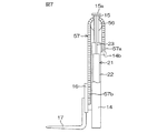
フォーク17を昇降させる動作の原理を概念的に示す図7を参照して、インナーマスト15の上部には、スプロケット56が回転可能に支持されており、そのスプロケット56には、チェーン57が巻き掛けられている。そのチェーン57の一端57aが、アウターマスト14に設けられた固定部14bに固定され、チェーン57の他端57bが、リフトブラケット16に固定されている。これにより、リフトブラケット16およびフォーク17が、チェーン57を用いて懸架されている。
Referring to FIG. 7 which conceptually shows the principle of the operation of raising and lowering the
リフトシリンダ21のロッド23の伸長に伴って、インナーマスト15が上昇すると、スプロケット56がアウターマスト14の固定部14bに対して上昇し、チェーン57を介して、リフトブラケット16および積載部としてのフォーク17を上昇させる。地表面に対するフォーク17の上昇量は、リフトシリンダ21のロッド23の伸長量の2倍となる。
When the
図8はフォークリフト1の主たる電気的構成を示すブロック図である。図8を参照して、ECU13には、操舵角センサ27、転舵角センサ28、車速センサ58、荷重センサ80、ユニットスライド位置センサ81、解除操作スイッチ85、昇降操作レバー36の位置を検出する昇降操作レバー位置センサ59、チルト操作レバー37の位置を検出するチルト操作レバー位置センサ60、および前進/後進切替レバー38の切替に応じて作動する前進/後進切替スイッチ61のそれぞれから信号が入力されるようになっている。
FIG. 8 is a block diagram showing the main electrical configuration of the forklift 1. Referring to FIG. 8, the
解除操作スイッチ85は、空荷のときに前方位置に移動されたユニット11を、次の積み荷のときの事前動作として、後方位置に戻すために、運転者が手動で操作するスイッチであり、図1では図示していないが、上記の操作スタンド35に設けられている。
また、ECU13から、操舵アクチュエータ25、反力アクチュエータ26、ユニットスライド用アクチュエータ47、ロック機構用ソレノイド62、油圧ポンプ8からリフトシリンダ21への作動油の供給を制御する電磁式の比例制御弁からなる昇降用制御弁63、油圧ポンプ8からチルトシリンダ18への作動油の供給を制御する電磁式の比例制御弁からなるチルト用制御弁64、前進クラッチを係合/離脱させるための油圧シリンダに作動油の供給を制御する電磁式比例制御弁からなる前進クラッチ用制御弁65、および後進クラッチを係合/離脱させるための油圧シリンダに作動油の供給を制御する電磁式比例制御弁からなる後進クラッチ用制御弁66のそれぞれに信号が出力されるようになっている。
The
The
ECU13は種々の制御を実行する。例えば、ECU13は、操舵角センサ27から入力した操舵角および車速センサ58から入力した車速に基づいて目標転舵角を決定し、転舵角センサ28から入力した転舵角を上記目標転舵角に近づけるように、操舵アクチュエータ25を駆動制御する(すなわち操舵制御を実施する)。
また、ECU13は、路面反力に応じた操舵反力を操舵部材24に与えるためのトルクを反力アクチュエータ26によって発生させるべく、操舵角センサ27から入力された操舵角および車速センサ58から入力された車速に基づいて、反力アクチュエータ26を駆動制御する(すなわち反力制御を実施する)。
The
Further, the
また、ECU13は、昇降操作レバー位置センサ59から入力された昇降操作レバー36の位置に応じて、油圧ポンプ8からリフトシリンダ21への作動油の供給を制御する昇降用制御弁63に制御信号を出力する。
また、ECU13は、チルト操作レバー位置センサ60から入力されたチルト操作レバー37の位置に応じて、油圧ポンプ8からチルトシリンダ18への作動油の供給を制御するチルト用制御弁64に制御信号を出力する。
Further, the
Further, the
また、ECU13は、前進/後進切替スイッチ61が前進へ切り替えられることに応じて前進クラッチ用制御弁65に制御信号を出力し、前進クラッチを作動させるための油圧シリンダに、油圧ポンプ8からの作動油が供給されるようにする。
また、ECU13は、前進/後進切替スイッチ61が後進へ切り替えられることに応じて後進クラッチ用制御弁66に制御信号を出力し、後進クラッチを作動させるための油圧シリンダに、油圧ポンプ8からの作動油が供給されるようにする。
In addition, the
Further, the
図9はECU13の主たる動作を示すフローチャートである。図9を参照して、ステップS1において、解除操作スイッチ85がオンされているか否かを確認し、オンされていない場合(ステップS1にてNOの場合)には、ステップS2において、荷重センサ80からの信号に基づいて、荷役装置3に負荷されている荷重Wを検出し、ステップS3において、検出された荷重Wが所定値W1以下(W≦W1)であってフォーク17に荷物を積載していない空荷の状態であるか否かを判定する。
FIG. 9 is a flowchart showing the main operation of the
ステップS3においてYES(空荷である)と判定されると、ステップS4において、ユニットスライド位置センサ81からの信号に基づいて、ユニット11が後方位置にあるか否かを判定し、ステップS4においてユニット11が後方位置にあると判定される(ステップS4でYESである)ことを条件として、ユニット11を前方位置へ移動させる。具体的には、ステップS5において、ロック機構52によるユニット11に対するロックを解除した後、ステップS6において、ユニットスライド用アクチュエータ47を駆動してユニット11を前方位置へ移動させる。その後、ステップS7において、ユニット11を前方位置にロックする。
If it is determined as YES (empty) in step S3, it is determined in step S4 whether or not the
一方、ステップS1において、解除操作スイッチ85がオンされていると判定された場合(ステップS1においてYESの場合)には、ステップS8において、ユニット11が前方位置にあるか否かを判定する。そのステップS8において、ユニット11が前方位置にあると判定される(ステップS8でYESである)ことを条件として、ユニット11を後方位置に移動させる。具体的には、ステップS9において、ロック機構52によるユニット11に対するロックを解除した後、ステップS10において、ユニットスライド用アクチュエータ47を駆動してユニット11を後方位置へ移動させる。その後、ステップS11において、ユニット11を後方位置にロックする。
On the other hand, if it is determined in step S1 that the
本実施の形態によれば、後部にカウンタウェイト4を備えるフォークリフト1において、運転座席10を含むユニット11を前後にスライドさせることにより、車両の前後の重量バランスを調整することができる。これにより、例えば空荷時の後輪6の接地荷重が過大になることを防止でき、その結果、空荷時に後輪6を転舵するときの操舵アクチュエータ25の駆動力を低減することができる。したがって、操舵アクチュエータ25の寿命を長くすることができる。また、小型の操舵アクチュエータ25を用いることが可能となる。さらに、空荷時の車両の前後の重量バランスが良くなるので、空荷時の車両の走行安定性を向上することができる。
According to the present embodiment, in the forklift 1 having the
また、荷重センサ80により検出された荷重Wに基づいて空荷であることを検出し、空荷を自動的に検出してユニット11をスライド方向X1前方にスライドさせる。したがって、運転者にとって面倒な操作なく、確実に、空荷時の後輪6の接地荷重を低減することができる。
また、ロック機構52によって、ユニット11を前方位置および後方位置にロックすることができる。ユニット11の位置のロックにより運転座席10が固定されるので、運転者の姿勢が安定し、操縦や車両駆動の操作がし易くなる。
Moreover, it detects that it is an empty load based on the load W detected by the
Further, the
また、上記ユニット11には、運転者が手または足で操作するための複数の操作要素および確認ミラー39が含まれている。具体的には、操舵部材24、昇降操作レバー36、チルト操作レバー37、前進/後進切替レバー38、アクセルペダル41、ブレーキペダル42、クラッチペダル43および確認ミラー39が含まれている。したがって、これらの操作要素等を、運転座席10とともにスライド変位させるので、運転者の運転し易さが格段に向上する。
The
また、上記ユニット11が荷役装置3を含んでいるので、ユニット11を車両前方へ少しの距離スライドさせるだけで、空荷時の後輪6の接地荷重を所定量に減らすことができる。したがって、ユニット11をスライドさせるときにユニットスライド用アクチュエータ47の負担すべきエネルギを削減することができ、省エネ上、好ましい。
また、車両用操舵装置9として、操舵部材24と転舵輪としての後輪6との間の機械的な連結が断たれたステアバイワイヤ式の車両用操舵装置が採用されているので、ユニット11の位置が変更されたときに、運転者が操舵部材24を容易に操作することができる。また、操舵部材24と転舵輪としての後輪6との間の機械的な連結が断たれているので、操舵部材24を運転座席10とともにスライド変位させることに困難性がない。
Further, since the
Further, as the
本発明は上記実施の形態に限定されるものではなく、例えば、上記実施の形態では、ユニット11に、操舵部材24、昇降操作レバー36、チルト操作レバー37、前進/後進切替レバー38、アクセルペダル41、ブレーキペダル42、クラッチペダル43および確認ミラー39が含まれていたが、これに限らず、ユニット11には、少なくとも運転座席10が含まれていればよい。
The present invention is not limited to the above embodiment. For example, in the above embodiment, the
また、空荷時にユニット11が前方位置に移動された状態で、フォーク17に荷物を積載してフォーク17が上昇されることを禁止するようにしてもよい。具体的には、昇降操作レバー位置センサ59が昇降操作位置にあることが検出されたときに、荷重センサ80により検出された荷重Wが所定値W1を超えている場合(空荷でない場合)には、リフトシリンダ21への作動油の供給を禁止するように、昇降用制御弁63を制御すればよい。その他、本発明の特許請求の範囲で種々の変更を施すことができる。
In addition, it may be prohibited to load the
1…フォークリフト(荷役車両)、2…車体、3…荷役装置、4…カウンタウェイト、5…前輪(駆動輪)、6…後輪(転舵輪)、7…駆動源、8…油圧ポンプ、9…車両用操舵装置、10…運転座席、11…ユニット、12…ユニット駆動機構、13…ECU(制御部)、17…フォーク(積載部)、18…チルトシリンダ、21…リフトシリンダ、24…操舵部材、25…操舵アクチュエータ、26…反力アクチュエータ、27…操舵角センサ、28…転舵角センサ、29…支持部材、30…軸受、31…伝達機構、34…ユニット本体、34A…底部フレーム、34B…側部フレーム、35…操作スタンド、36…昇降操作レバー(操作要素)、37…チルト操作レバー(操作要素)、38…前進/後進切替レバー(操作要素)、39…確認ミラー、40…案内機構、41…アクセルペダル(操作要素)、42…ブレーキペダル(操作要素)、43…クラッチペダル(操作要素)、44…案内レール(案内部材)、45…支軸、46…転動部材(被案内部材)、47…ユニットスライド用アクチュエータ、48…伝達機構、50…ピニオン、51…ラック、52…ロック機構、53…ロック部材、53a…本体、53b…ロック軸、54…第1のロック孔、55…第2のロック孔、61…前進/後進切替スイッチ(後退検出手段。前進検出手段)、62…ロック機構用ソレノイド、80…荷重センサ、81…ユニットスライド位置センサ、85…解除操作スイッチ、X1…スライド方向
DESCRIPTION OF SYMBOLS 1 ... Forklift (cargo handling vehicle), 2 ... Vehicle body, 3 ... Cargo handling device, 4 ... Counterweight, 5 ... Front wheel (drive wheel), 6 ... Rear wheel (steered wheel), 7 ... Drive source, 8 ... Hydraulic pump, 9 DESCRIPTION OF SYMBOLS ... Steering device for vehicles, 10 ... Driving seat, 11 ... Unit, 12 ... Unit drive mechanism, 13 ... ECU (control part), 17 ... Fork (loading part), 18 ... Tilt cylinder, 21 ... Lift cylinder, 24 ...
Claims (4)
操舵部材と、
操舵部材の操作に応じて転舵輪としての後輪を転舵するための操舵力を発生する操舵アクチュエータと、
少なくとも運転座席を含み、上記車体によって車両の前後方向に沿うスライド方向にスライド可能に支持されたユニットと、
上記スライド方向に沿って上記ユニットを移動させるための駆動機構と、
上記荷役装置が受ける荷重を検出するための荷重センサと、
上記荷重センサにより検出された荷重が所定値以下のときに、上記ユニットを上記スライド方向前方にスライドさせるように、上記駆動機構を制御する制御部とを備えたことを特徴とする車両用操舵装置。 In a vehicle steering apparatus for steering a cargo handling vehicle provided with a cargo handling device at the front of the vehicle body and with a counterweight at the rear of the vehicle body,
A steering member;
A steering actuator that generates a steering force for steering the rear wheel as a steered wheel in accordance with an operation of the steering member;
A unit including at least a driver's seat and supported by the vehicle body so as to be slidable in a sliding direction along a longitudinal direction of the vehicle;
A drive mechanism for moving the unit along the sliding direction;
A load sensor for detecting a load received by the cargo handling device;
When it is detected load less than a predetermined value by the load sensors, the unit so as to slide forward the sliding direction, the vehicle steering apparatus characterized by comprising a control unit for controlling the drive mechanism .
Priority Applications (1)
| Application Number | Priority Date | Filing Date | Title |
|---|---|---|---|
| JP2008307768A JP5305085B2 (en) | 2008-12-02 | 2008-12-02 | Vehicle steering system |
Applications Claiming Priority (1)
| Application Number | Priority Date | Filing Date | Title |
|---|---|---|---|
| JP2008307768A JP5305085B2 (en) | 2008-12-02 | 2008-12-02 | Vehicle steering system |
Publications (3)
| Publication Number | Publication Date |
|---|---|
| JP2010132380A JP2010132380A (en) | 2010-06-17 |
| JP2010132380A5 JP2010132380A5 (en) | 2013-03-14 |
| JP5305085B2 true JP5305085B2 (en) | 2013-10-02 |
Family
ID=42344100
Family Applications (1)
| Application Number | Title | Priority Date | Filing Date |
|---|---|---|---|
| JP2008307768A Expired - Fee Related JP5305085B2 (en) | 2008-12-02 | 2008-12-02 | Vehicle steering system |
Country Status (1)
| Country | Link |
|---|---|
| JP (1) | JP5305085B2 (en) |
Cited By (1)
| Publication number | Priority date | Publication date | Assignee | Title |
|---|---|---|---|---|
| CN103287487A (en) * | 2013-05-30 | 2013-09-11 | 安徽德摩新能源叉车股份有限公司 | Four-way forklift structure |
Families Citing this family (4)
| Publication number | Priority date | Publication date | Assignee | Title |
|---|---|---|---|---|
| JP5569735B2 (en) * | 2010-08-24 | 2014-08-13 | 株式会社ジェイテクト | Vehicle steering system |
| JP5854265B2 (en) * | 2011-11-08 | 2016-02-09 | 株式会社ジェイテクト | Steering mechanism control device |
| JP7220124B2 (en) * | 2019-06-11 | 2023-02-09 | 三菱重工業株式会社 | Automatic guided vehicle, control device and program |
| CN117583405B (en) * | 2024-01-18 | 2024-04-05 | 三鑫特材(常州)股份有限公司 | U-turn machine for steel ingot rolling |
Family Cites Families (3)
| Publication number | Priority date | Publication date | Assignee | Title |
|---|---|---|---|---|
| JPS5414368Y2 (en) * | 1974-04-30 | 1979-06-14 | ||
| JPS60107099U (en) * | 1983-12-23 | 1985-07-20 | 株式会社豊田自動織機製作所 | Forklift truck cab moving device |
| JP2008068830A (en) * | 2006-09-15 | 2008-03-27 | Mitsubishi Agricult Mach Co Ltd | Working vehicle |
-
2008
- 2008-12-02 JP JP2008307768A patent/JP5305085B2/en not_active Expired - Fee Related
Cited By (1)
| Publication number | Priority date | Publication date | Assignee | Title |
|---|---|---|---|---|
| CN103287487A (en) * | 2013-05-30 | 2013-09-11 | 安徽德摩新能源叉车股份有限公司 | Four-way forklift structure |
Also Published As
| Publication number | Publication date |
|---|---|
| JP2010132380A (en) | 2010-06-17 |
Similar Documents
| Publication | Publication Date | Title |
|---|---|---|
| JP5645069B2 (en) | Vehicle steering system | |
| JP5305085B2 (en) | Vehicle steering system | |
| JP5392550B2 (en) | Vehicle steering system | |
| CN113302146B (en) | Forklift truck | |
| JP2008179465A (en) | Travel control apparatus for industrial vehicle | |
| EP3020678B1 (en) | Apparatus for controlling load handling device | |
| KR100604686B1 (en) | Control system of industrial truck and controlling method of the same | |
| JP2015101113A (en) | Steering device, industrial vehicle and program | |
| JPH07101698A (en) | Speed control mechanism for elevated spot work vehicle | |
| JP2010254237A (en) | Steering device for vehicle | |
| JP5354264B2 (en) | Vehicle steering system | |
| JP5569735B2 (en) | Vehicle steering system | |
| JP2011132002A (en) | Reach forklift truck | |
| JP2014185005A (en) | Cargo-handling vehicle | |
| JP2004244144A (en) | Pallet lock device for forklift | |
| JP2010132379A (en) | Cargo handling vehicle | |
| JP4732060B2 (en) | Steering device for work vehicle | |
| JP2004269236A (en) | Forklift | |
| JP2010254236A (en) | Steering device for vehicle | |
| JP2012076651A (en) | Vehicle steering device | |
| JP5278755B2 (en) | Vehicle steering system | |
| JP5403334B2 (en) | Vehicle steering system | |
| JP3539346B2 (en) | Reach forklift | |
| JP5459732B2 (en) | Side forklift | |
| JP7003718B2 (en) | Industrial vehicle |
Legal Events
| Date | Code | Title | Description |
|---|---|---|---|
| A621 | Written request for application examination |
Free format text: JAPANESE INTERMEDIATE CODE: A621 Effective date: 20110928 |
|
| A521 | Written amendment |
Free format text: JAPANESE INTERMEDIATE CODE: A523 Effective date: 20120725 |
|
| A521 | Written amendment |
Free format text: JAPANESE INTERMEDIATE CODE: A523 Effective date: 20130128 |
|
| TRDD | Decision of grant or rejection written | ||
| A01 | Written decision to grant a patent or to grant a registration (utility model) |
Free format text: JAPANESE INTERMEDIATE CODE: A01 Effective date: 20130530 |
|
| A977 | Report on retrieval |
Free format text: JAPANESE INTERMEDIATE CODE: A971007 Effective date: 20130531 |
|
| A61 | First payment of annual fees (during grant procedure) |
Free format text: JAPANESE INTERMEDIATE CODE: A61 Effective date: 20130612 |
|
| R150 | Certificate of patent or registration of utility model |
Free format text: JAPANESE INTERMEDIATE CODE: R150 |
|
| LAPS | Cancellation because of no payment of annual fees |