JP5551899B2 - Information processing system, information processing apparatus, information processing program - Google Patents
Information processing system, information processing apparatus, information processing program Download PDFInfo
- Publication number
- JP5551899B2 JP5551899B2 JP2009165688A JP2009165688A JP5551899B2 JP 5551899 B2 JP5551899 B2 JP 5551899B2 JP 2009165688 A JP2009165688 A JP 2009165688A JP 2009165688 A JP2009165688 A JP 2009165688A JP 5551899 B2 JP5551899 B2 JP 5551899B2
- Authority
- JP
- Japan
- Prior art keywords
- video
- data
- information processing
- reproduction
- control data
- Prior art date
- Legal status (The legal status is an assumption and is not a legal conclusion. Google has not performed a legal analysis and makes no representation as to the accuracy of the status listed.)
- Active
Links
Images


Classifications
-
- A—HUMAN NECESSITIES
- A63—SPORTS; GAMES; AMUSEMENTS
- A63F—CARD, BOARD, OR ROULETTE GAMES; INDOOR GAMES USING SMALL MOVING PLAYING BODIES; VIDEO GAMES; GAMES NOT OTHERWISE PROVIDED FOR
- A63F13/00—Video games, i.e. games using an electronically generated display having two or more dimensions
- A63F13/60—Generating or modifying game content before or while executing the game program, e.g. authoring tools specially adapted for game development or game-integrated level editor
-
- A—HUMAN NECESSITIES
- A63—SPORTS; GAMES; AMUSEMENTS
- A63F—CARD, BOARD, OR ROULETTE GAMES; INDOOR GAMES USING SMALL MOVING PLAYING BODIES; VIDEO GAMES; GAMES NOT OTHERWISE PROVIDED FOR
- A63F13/00—Video games, i.e. games using an electronically generated display having two or more dimensions
- A63F13/30—Interconnection arrangements between game servers and game devices; Interconnection arrangements between game devices; Interconnection arrangements between game servers
- A63F13/33—Interconnection arrangements between game servers and game devices; Interconnection arrangements between game devices; Interconnection arrangements between game servers using wide area network [WAN] connections
- A63F13/332—Interconnection arrangements between game servers and game devices; Interconnection arrangements between game devices; Interconnection arrangements between game servers using wide area network [WAN] connections using wireless networks, e.g. cellular phone networks
-
- A—HUMAN NECESSITIES
- A63—SPORTS; GAMES; AMUSEMENTS
- A63F—CARD, BOARD, OR ROULETTE GAMES; INDOOR GAMES USING SMALL MOVING PLAYING BODIES; VIDEO GAMES; GAMES NOT OTHERWISE PROVIDED FOR
- A63F13/00—Video games, i.e. games using an electronically generated display having two or more dimensions
- A63F13/70—Game security or game management aspects
- A63F13/77—Game security or game management aspects involving data related to game devices or game servers, e.g. configuration data, software version or amount of memory
-
- A—HUMAN NECESSITIES
- A63—SPORTS; GAMES; AMUSEMENTS
- A63F—CARD, BOARD, OR ROULETTE GAMES; INDOOR GAMES USING SMALL MOVING PLAYING BODIES; VIDEO GAMES; GAMES NOT OTHERWISE PROVIDED FOR
- A63F13/00—Video games, i.e. games using an electronically generated display having two or more dimensions
- A63F13/90—Constructional details or arrangements of video game devices not provided for in groups A63F13/20 or A63F13/25, e.g. housing, wiring, connections or cabinets
- A63F13/92—Video game devices specially adapted to be hand-held while playing
-
- H—ELECTRICITY
- H04—ELECTRIC COMMUNICATION TECHNIQUE
- H04N—PICTORIAL COMMUNICATION, e.g. TELEVISION
- H04N21/00—Selective content distribution, e.g. interactive television or video on demand [VOD]
- H04N21/40—Client devices specifically adapted for the reception of or interaction with content, e.g. set-top-box [STB]; Operations thereof
- H04N21/41—Structure of client; Structure of client peripherals
- H04N21/4104—Peripherals receiving signals from specially adapted client devices
- H04N21/4126—The peripheral being portable, e.g. PDAs or mobile phones
- H04N21/41265—The peripheral being portable, e.g. PDAs or mobile phones having a remote control device for bidirectional communication between the remote control device and client device
-
- H—ELECTRICITY
- H04—ELECTRIC COMMUNICATION TECHNIQUE
- H04N—PICTORIAL COMMUNICATION, e.g. TELEVISION
- H04N21/00—Selective content distribution, e.g. interactive television or video on demand [VOD]
- H04N21/40—Client devices specifically adapted for the reception of or interaction with content, e.g. set-top-box [STB]; Operations thereof
- H04N21/43—Processing of content or additional data, e.g. demultiplexing additional data from a digital video stream; Elementary client operations, e.g. monitoring of home network or synchronising decoder's clock; Client middleware
- H04N21/436—Interfacing a local distribution network, e.g. communicating with another STB or one or more peripheral devices inside the home
- H04N21/43615—Interfacing a Home Network, e.g. for connecting the client to a plurality of peripherals
-
- H—ELECTRICITY
- H04—ELECTRIC COMMUNICATION TECHNIQUE
- H04N—PICTORIAL COMMUNICATION, e.g. TELEVISION
- H04N21/00—Selective content distribution, e.g. interactive television or video on demand [VOD]
- H04N21/40—Client devices specifically adapted for the reception of or interaction with content, e.g. set-top-box [STB]; Operations thereof
- H04N21/43—Processing of content or additional data, e.g. demultiplexing additional data from a digital video stream; Elementary client operations, e.g. monitoring of home network or synchronising decoder's clock; Client middleware
- H04N21/436—Interfacing a local distribution network, e.g. communicating with another STB or one or more peripheral devices inside the home
- H04N21/4363—Adapting the video or multiplex stream to a specific local network, e.g. a IEEE 1394 or Bluetooth® network
- H04N21/43637—Adapting the video or multiplex stream to a specific local network, e.g. a IEEE 1394 or Bluetooth® network involving a wireless protocol, e.g. Bluetooth, RF or wireless LAN [IEEE 802.11]
-
- A—HUMAN NECESSITIES
- A63—SPORTS; GAMES; AMUSEMENTS
- A63F—CARD, BOARD, OR ROULETTE GAMES; INDOOR GAMES USING SMALL MOVING PLAYING BODIES; VIDEO GAMES; GAMES NOT OTHERWISE PROVIDED FOR
- A63F13/00—Video games, i.e. games using an electronically generated display having two or more dimensions
- A63F13/25—Output arrangements for video game devices
- A63F13/26—Output arrangements for video game devices having at least one additional display device, e.g. on the game controller or outside a game booth
-
- A—HUMAN NECESSITIES
- A63—SPORTS; GAMES; AMUSEMENTS
- A63F—CARD, BOARD, OR ROULETTE GAMES; INDOOR GAMES USING SMALL MOVING PLAYING BODIES; VIDEO GAMES; GAMES NOT OTHERWISE PROVIDED FOR
- A63F13/00—Video games, i.e. games using an electronically generated display having two or more dimensions
- A63F13/30—Interconnection arrangements between game servers and game devices; Interconnection arrangements between game devices; Interconnection arrangements between game servers
- A63F13/32—Interconnection arrangements between game servers and game devices; Interconnection arrangements between game devices; Interconnection arrangements between game servers using local area network [LAN] connections
- A63F13/323—Interconnection arrangements between game servers and game devices; Interconnection arrangements between game devices; Interconnection arrangements between game servers using local area network [LAN] connections between game devices with different hardware characteristics, e.g. hand-held game devices connectable to game consoles or arcade machines
-
- A—HUMAN NECESSITIES
- A63—SPORTS; GAMES; AMUSEMENTS
- A63F—CARD, BOARD, OR ROULETTE GAMES; INDOOR GAMES USING SMALL MOVING PLAYING BODIES; VIDEO GAMES; GAMES NOT OTHERWISE PROVIDED FOR
- A63F13/00—Video games, i.e. games using an electronically generated display having two or more dimensions
- A63F13/50—Controlling the output signals based on the game progress
- A63F13/53—Controlling the output signals based on the game progress involving additional visual information provided to the game scene, e.g. by overlay to simulate a head-up display [HUD] or displaying a laser sight in a shooting game
- A63F13/533—Controlling the output signals based on the game progress involving additional visual information provided to the game scene, e.g. by overlay to simulate a head-up display [HUD] or displaying a laser sight in a shooting game for prompting the player, e.g. by displaying a game menu
-
- A—HUMAN NECESSITIES
- A63—SPORTS; GAMES; AMUSEMENTS
- A63F—CARD, BOARD, OR ROULETTE GAMES; INDOOR GAMES USING SMALL MOVING PLAYING BODIES; VIDEO GAMES; GAMES NOT OTHERWISE PROVIDED FOR
- A63F13/00—Video games, i.e. games using an electronically generated display having two or more dimensions
- A63F13/80—Special adaptations for executing a specific game genre or game mode
- A63F13/822—Strategy games; Role-playing games
-
- A—HUMAN NECESSITIES
- A63—SPORTS; GAMES; AMUSEMENTS
- A63F—CARD, BOARD, OR ROULETTE GAMES; INDOOR GAMES USING SMALL MOVING PLAYING BODIES; VIDEO GAMES; GAMES NOT OTHERWISE PROVIDED FOR
- A63F13/00—Video games, i.e. games using an electronically generated display having two or more dimensions
- A63F13/90—Constructional details or arrangements of video game devices not provided for in groups A63F13/20 or A63F13/25, e.g. housing, wiring, connections or cabinets
- A63F13/98—Accessories, i.e. detachable arrangements optional for the use of the video game device, e.g. grip supports of game controllers
-
- A—HUMAN NECESSITIES
- A63—SPORTS; GAMES; AMUSEMENTS
- A63F—CARD, BOARD, OR ROULETTE GAMES; INDOOR GAMES USING SMALL MOVING PLAYING BODIES; VIDEO GAMES; GAMES NOT OTHERWISE PROVIDED FOR
- A63F2300/00—Features of games using an electronically generated display having two or more dimensions, e.g. on a television screen, showing representations related to the game
- A63F2300/40—Features of games using an electronically generated display having two or more dimensions, e.g. on a television screen, showing representations related to the game characterised by details of platform network
- A63F2300/402—Communication between platforms, i.e. physical link to protocol
-
- A—HUMAN NECESSITIES
- A63—SPORTS; GAMES; AMUSEMENTS
- A63F—CARD, BOARD, OR ROULETTE GAMES; INDOOR GAMES USING SMALL MOVING PLAYING BODIES; VIDEO GAMES; GAMES NOT OTHERWISE PROVIDED FOR
- A63F2300/00—Features of games using an electronically generated display having two or more dimensions, e.g. on a television screen, showing representations related to the game
- A63F2300/40—Features of games using an electronically generated display having two or more dimensions, e.g. on a television screen, showing representations related to the game characterised by details of platform network
- A63F2300/403—Connection between platform and handheld device
-
- A—HUMAN NECESSITIES
- A63—SPORTS; GAMES; AMUSEMENTS
- A63F—CARD, BOARD, OR ROULETTE GAMES; INDOOR GAMES USING SMALL MOVING PLAYING BODIES; VIDEO GAMES; GAMES NOT OTHERWISE PROVIDED FOR
- A63F2300/00—Features of games using an electronically generated display having two or more dimensions, e.g. on a television screen, showing representations related to the game
- A63F2300/50—Features of games using an electronically generated display having two or more dimensions, e.g. on a television screen, showing representations related to the game characterized by details of game servers
- A63F2300/55—Details of game data or player data management
- A63F2300/552—Details of game data or player data management for downloading to client devices, e.g. using OS version, hardware or software profile of the client device
Description
本発明は、第1の情報処理装置および第2の情報処理装置を備えた情報処理システムに関し、より特定的には、第1の情報処理装置と第2の情報処理装置を連動させて処理を行う情報処理システムに関する。 The present invention relates to an information processing system including a first information processing apparatus and a second information processing apparatus, and more specifically, performs processing by linking a first information processing apparatus and a second information processing apparatus. The present invention relates to an information processing system.
従来より、2つの情報処理装置を連動させた情報処理システムが存在している。例えば、携帯型ゲーム機と据置型ゲーム機をワイヤレス通信によって接続し、携帯型ゲーム機の操作によって、据置型ゲーム機で展開されるゲームに対して指示を出すことができるゲームシステムが開示されている(例えば、非特許文献1)。また、携帯型ゲーム機のゲームソフトで収集し保存されているキャラクタを、据置型ゲーム機のゲームソフトに転送することができるゲームシステムも開示されている(例えば、非特許文献2)。当該ゲームシステムでは、携帯型ゲーム機側で据置型ゲーム機へキャラクタの転送を指示することにより、携帯型ゲーム機から据置型ゲーム機に当該キャラクタが移動する。また、据置型ゲーム機に移動させたキャラクタを携帯型ゲーム機に戻すこともできる。 Conventionally, there has been an information processing system in which two information processing apparatuses are linked. For example, a game system is disclosed in which a portable game machine and a stationary game machine are connected by wireless communication, and an instruction can be issued to a game deployed on the stationary game machine by operating the portable game machine. (For example, Non-Patent Document 1). Also disclosed is a game system that can transfer characters collected and stored by game software of a portable game machine to game software of a stationary game machine (for example, Non-Patent Document 2). In the game system, when the portable game machine instructs the transfer of the character to the stationary game machine, the character moves from the portable game machine to the stationary game machine. Further, the character moved to the stationary game machine can be returned to the portable game machine.
しかしながら、上記非特許文献1に開示されているゲームシステムは、ある情報処理装置の操作を他の情報処理装置を用いて行うことができるというものである。また、上記非特許文献2に開示されているゲームシステムは、2つの情報処理装置間でデータのやり取りをできるというものである。いずれのゲームシステムも、ある情報処理装置で実行されるアプリケーションに応じて、他の情報処理装置で再生される映像が変化するというものではなかった。
However, the game system disclosed in Non-Patent
それ故に、本発明の目的は、ある情報処理装置で実行されるアプリケーションに応じて、他の情報処理装置で再生される映像を変化させることのできる、新規な情報処理システムを提供することである。 SUMMARY OF THE INVENTION Therefore, an object of the present invention is to provide a novel information processing system capable of changing a video reproduced on another information processing apparatus in accordance with an application executed on the information processing apparatus. .
本発明は、上記の課題を解決するために、以下の構成を採用した。 The present invention employs the following configuration in order to solve the above problems.
第1の発明は、第1の情報処理装置および第2の情報処理装置を備えたシステムであって、第1の情報処理装置は、実行手段と、制御用データ作成手段と、第1の送信手段とを備える。実行手段は、アプリケーションを実行する。制御用データ作成手段は、アプリケーションの実行状況に応じて制御用データを生成する。第1の送信手段は、制御用データを第2の情報処理装置に送信する。第2の情報処理装置は、映像記憶手段と、映像再生手段と、受信手段と、再生映像決定手段とを備える。映像記憶手段は、少なくとも1つの映像データを記憶する。映像再生手段は、映像記憶手段に記憶されている映像データに基づいて映像を再生する。受信手段は、第1の送信手段で送信された制御用データを受信する。再生映像決定手段は、受信した制御用データに基づいて、映像再生手段に再生させる映像を決定する。そして、映像再生手段は、再生映像決定手段で決定された映像を映像データに基づいて再生する。 A first invention is a system including a first information processing apparatus and a second information processing apparatus, and the first information processing apparatus includes an execution unit, a control data generation unit, and a first transmission. Means. The execution means executes the application. The control data creation means generates control data according to the execution status of the application. The first transmission means transmits the control data to the second information processing apparatus. The second information processing apparatus includes a video storage unit, a video playback unit, a reception unit, and a playback video determination unit. The video storage means stores at least one video data. The video reproduction means reproduces the video based on the video data stored in the video storage means. The receiving unit receives the control data transmitted by the first transmitting unit. The reproduced video determining means determines the video to be reproduced by the video reproducing means based on the received control data. The video reproduction means reproduces the video determined by the reproduction video determination means based on the video data.
第1の発明によれば、第1の情報処理装置におけるアプリケーションの実行状況に応じて、第2の情報処理装置で再生される映像を変化させることができる。これにより、今までにない新たな楽しみ方ができるゲーム処理等の情報処理が行われるシステムを提供することができる According to the first invention, it is possible to change the video reproduced by the second information processing apparatus in accordance with the execution status of the application in the first information processing apparatus. As a result, it is possible to provide a system in which information processing such as game processing that allows a new way of enjoying that has never been performed is performed.
第2の発明は、第1の発明において、第2の情報処理装置は、アプリケーション記憶手段と、第2の送信手段を更に備える。
アプリケーション記憶手段は、アプリケーションを記憶する。第2の送信手段は、アプリケーション記憶手段に記憶されているアプリケーションを第1の情報処理装置に送信する。そして、実行手段は、第1の送信手段によって送信されたアプリケーションを実行する。
In a second aspect based on the first aspect, the second information processing apparatus further includes an application storage unit and a second transmission unit.
The application storage means stores an application. The second transmission unit transmits the application stored in the application storage unit to the first information processing apparatus. Then, the execution means executes the application transmitted by the first transmission means.
第2の発明によれば、第2の情報処理装置に映像とアプリケーションが記憶させ、このうちアプリケーションのみを第1の情報処理装置に配信することが可能となる。 According to the second invention, the video and the application are stored in the second information processing apparatus, and only the application can be distributed to the first information processing apparatus.
第3の発明は、第1の発明において、制御用データは、映像データに含まれる映像のうちの一部分を指定するためのデータである。そして、再生映像決定手段は、受信された制御用データに基づいて、映像データに含まれる映像のうちの一部分の映像を決定する。更に、映像再生手段は、再生映像決定手段で決定された一部分の映像を再生する。 In a third aspect based on the first aspect, the control data is data for designating a part of the video included in the video data. Then, the reproduced video determining means determines a part of the video included in the video data based on the received control data. Further, the video reproduction means reproduces a part of the video determined by the reproduction video determination means.
第3の発明によれば、映像の再生部分を特定して第2の情報処理装置に再生させることが可能となる。また、第2の情報処理装置で再生される映像を第1の情報処理装置が指定するため、第2の情報処理装置では当該指定に基づく動画の再生処理のみ行うだけで足り、第2の情報処理装置の処理負荷を軽減することができる。 According to the third aspect, it is possible to specify the playback portion of the video and cause the second information processing apparatus to play it back. In addition, since the first information processing device designates the video to be reproduced by the second information processing device, the second information processing device only needs to perform the reproduction processing of the moving image based on the designation. The processing load on the processing apparatus can be reduced.
第4の発明は、第1の発明において、第1の情報処理装置は、アプリケーションの実行状況に応じて、再生候補として予め定義されている複数の候補映像のそれぞれを示す情報のうちから1つをランダムに指定する映像指定手段を更に備える。そして、制御用データ作成手段は、映像指定手段で指定された映像を示す情報を含むデータを制御用データとして作成する。 In a fourth aspect based on the first aspect, the first information processing apparatus is configured to select one piece of information indicating each of a plurality of candidate videos that are defined in advance as reproduction candidates according to an execution state of the application. Video designation means for randomly designating the video. The control data creation means creates data including information indicating the video designated by the video designation means as control data.
第4の発明によれば、再生される映像のパターンに変化を持たせることができ、プレイヤに飽きの来ない情報処理システムが提供可能となる。 According to the fourth aspect of the present invention, it is possible to provide an information processing system that can give a change to the pattern of the reproduced video and does not get tired of the player.
第5の発明は、第4の発明において、第1の情報処理装置は、アプリケーションの実行状況が第1の条件または第2の条件のいずれかを満たしたか否かを判別する第1判別手段を更に備える。そして、映像指定手段は、第1判別手段によって、第1の条件が満たされたことが判別されたときは、予め定義されている所定の映像を示す情報を指定し、第1判別手段によって、第2の条件が満たされたことが判別されたときは、再生候補として予め定義されている複数の候補映像それぞれを示す情報のうちから1つをランダムに指定する。 In a fifth aspect based on the fourth aspect, the first information processing apparatus further comprises a first determination unit configured to determine whether the execution status of the application satisfies either the first condition or the second condition. In addition. The video designating unit designates information indicating a predetermined video defined in advance when the first discriminating unit discriminates that the first condition is satisfied, and the first discriminating unit When it is determined that the second condition is satisfied, one of information indicating each of a plurality of candidate videos defined in advance as reproduction candidates is randomly specified.
第5の発明によれば、アプリケーションの実行状況に応じて、第2の情報処理装置で再生すべき映像の指定方法を変えることができる。 According to the fifth aspect, it is possible to change the designation method of the video to be played back by the second information processing apparatus in accordance with the execution status of the application.
第6の発明は、第1の発明において、制御用データ作成手段は、アプリケーションの実行状況に応じて、映像の再生を繰り返すことを指示するループ再生指示を含んだ制御用データを作成する。そして、映像再生手段は、受信した制御用データにループ再生指示が含まれているときは、受信手段がその後新たに制御用データを受信するまでの間は、映像決定手段で決定された映像を繰り返し再生する。 In a sixth aspect based on the first aspect, the control data creation means creates control data including a loop playback instruction that instructs to repeat video playback according to the execution status of the application. Then, when the received control data includes a loop playback instruction, the video playback means displays the video determined by the video determination means until the receiving means receives new control data thereafter. Play repeatedly.
第6の発明によれば、ある映像の再生が終了したときに、第2の情報処理装置において静止画が表示されたまま止まった状態となることを防ぎ、より臨場感を高めることが可能となる。 According to the sixth aspect of the present invention, it is possible to prevent a still image from being stopped while being displayed on the second information processing apparatus when playback of a certain video is finished, and to further enhance the sense of reality. Become.
第7の発明は、第1の発明において、制御用データ作成手段は、アプリケーションの実行状況に応じて、映像の再生を繰り返すことを指示するループ再生指示、または、映像の再生を1度だけ行うことを指示するワンプレイ指示のいずれかを含んだ制御用データを作成する。そして、映像再生手段は、受信した制御用データにループ再生指示が含まれているときは、受信手段がその後新たに制御用データを受信するまでの間は、映像決定手段で決定された映像を繰り返し再生し、受信した制御用データにワンプレイ指示が含まれているときは、映像決定手段で決定された映像を一度だけ再生する。 In a seventh aspect based on the first aspect, the control data creating means performs a loop reproduction instruction for instructing to repeat the reproduction of the video or a video reproduction only once according to the execution state of the application. Control data including any one-play instruction is issued. Then, when the received control data includes a loop playback instruction, the video playback means displays the video determined by the video determination means until the receiving means receives new control data thereafter. When the one-play instruction is included in the received control data, the video determined by the video determination means is played only once.
第7の発明によれば、アプリケーションの実行状況に応じて、映像の再生方法を変化させることができる。 According to the seventh aspect, the video playback method can be changed according to the execution status of the application.
第8の発明は、第4の発明において、第2の情報処理装置は、映像決定手段で決定された映像の再生が終了したとき、第1の情報処理装置に映像の再生が終了したことを示す再生完了データを送信する第2の送信手段を更に備える。また、第1の情報処理装置は、第2の送信手段から送信された再生完了データを受信するための第2の受信手段を更に備える。そして、第2の受信手段が再生完了データを受信したとき、映像指定手段は、再生候補として予め定義されている複数の候補映像それぞれを示す情報のうちから1つをランダムに指定する。 In an eighth aspect based on the fourth aspect, when the second information processing apparatus finishes reproducing the video to the first information processing apparatus when the reproduction of the video determined by the video determining means is completed. Second transmission means for transmitting the reproduction completion data shown is further provided. The first information processing apparatus further includes second receiving means for receiving the reproduction completion data transmitted from the second transmitting means. Then, when the second receiving unit receives the reproduction completion data, the video designating unit randomly designates one of information indicating each of the plurality of candidate videos defined in advance as reproduction candidates.
第8の発明によれば、ある映像の再生が終了したときに、第2の情報処理装置において静止画が表示されたまま止まった状態となることを防ぎ、且つ、同じ映像が繰り返し再生されることによる不自然さを解消することが可能となる。 According to the eighth invention, when the reproduction of a certain video is finished, the second information processing apparatus prevents the still image from being stopped and displays the same video repeatedly. It becomes possible to eliminate the unnaturalness caused by this.
第9の発明は、第1の発明において、第2の情報処理装置は、映像決定手段で決定された映像の再生が終了したとき、第1の情報処理装置に映像の再生が終了したことを示す再生完了データを送信する第2の送信手段を更に備える。また、第1の情報処理装置は、映像指定手段と、第2の受信手段と、第2の判別手段とを更に備える。映像指定手段は、アプリケーションの実行状況に応じて、再生候補として予め定義されている複数の候補映像を示す情報のうちから1つをランダムに指定する。第2の受信手段は、第2の送信手段から送信された再生完了データを受信する。第2の判別手段は、アプリケーションの実行状況が第3の条件を満たしたか否かを判別する。映像指定手段は、再生候補として予め定義されている複数の映像を示す情報のうち、少なくとも2つ以上の映像を含む第1の候補映像群から1つの映像を示す情報をランダムに指定する。このような構成において、制御用データ作成手段は、指定された映像を示す情報を含む制御用データを作成する。そして、第2の情報処理装置で制御用データに基づく映像の再生が開始された後、第2の受信手段で再生完了データが受信されたときにおいて、第2の判別手段において第3の条件が満たされていないと判別されたときは、映像指定手段は、第1の候補映像群から次に再生すべき映像を示す情報をランダムに指定し、当該第3の条件を満たしたと判別されたときは、映像指定手段は、第1の候補映像群とは異なる複数の映像を含む第2の候補映像群から次に再生すべき映像を示す情報をランダムに指定する。 According to a ninth aspect, in the first aspect, the second information processing apparatus indicates that the reproduction of the video has been completed by the first information processing apparatus when the reproduction of the video determined by the video determination means has been completed. Second transmission means for transmitting the reproduction completion data shown is further provided. The first information processing apparatus further includes a video designating unit, a second receiving unit, and a second determining unit. The video designating means randomly designates one of information indicating a plurality of candidate videos that are defined in advance as playback candidates according to the execution status of the application. The second receiving unit receives the reproduction completion data transmitted from the second transmitting unit. The second determining means determines whether or not the execution status of the application satisfies the third condition. The video designating means randomly designates information indicating one video from a first candidate video group including at least two or more videos among information indicating a plurality of videos predefined as reproduction candidates. In such a configuration, the control data creating means creates control data including information indicating the designated video. Then, after the reproduction of the video based on the control data is started by the second information processing apparatus, when the reproduction completion data is received by the second receiving means, the third condition is satisfied by the second determining means. When it is determined that the condition is not satisfied, the image specifying unit randomly specifies information indicating an image to be reproduced next from the first candidate image group, and when it is determined that the third condition is satisfied The video designation means randomly designates information indicating the video to be reproduced next from the second candidate video group including a plurality of videos different from the first candidate video group.
第9の発明によれば、再生中の映像が終了したときと、アプリケーションの実行状況が所定の条件を満たした場合とで、第2の情報処理装置に次に再生させる映像を異なる候補映像群から選択することが可能となる。 According to the ninth invention, different video images to be reproduced next by the second information processing apparatus are displayed when the video being reproduced ends and when the execution status of the application satisfies a predetermined condition. It becomes possible to select from.
第10の発明は、第1の発明において、第1の情報処理装置は、アプリケーションの実行状況に応じて、映像データに含まれる映像の再生開始フレーム番号と再生終了フレーム番号を指定するフレーム指定手段を更に備える。そして、制御用データ作成手段は、フレーム指定手段による指定内容を含めた制御用データを作成する。 According to a tenth aspect, in the first aspect, the first information processing apparatus is a frame designating unit for designating a reproduction start frame number and a reproduction end frame number of a video included in the video data according to an execution state of the application. Is further provided. Then, the control data creation means creates control data including the contents specified by the frame designation means.
第10の発明によれば、汎用性が高く、簡易な指定方法で映像の再生部分を指定することが可能となる。 According to the tenth aspect of the invention, it is highly versatile and it is possible to designate a playback part of a video by a simple designation method.
第11の発明は、第1の発明において、情報処理システムは、映像データおよびアプリケーションを記憶したサーバを更に備える。当該サーバは、第2の情報処理装置へ映像データおよびアプリケーションを送信する第3の送信手段を備える。また、第2の情報処理装置は、第3の送信手段で送信された映像データおよびアプリケーションを受信する第3の受信手段と、第3の受信手段で受信したアプリケーションを第1の情報処理装置へ送信する第4の送信手段とを更に備える。また、第1の情報処理装置は、第4の送信手段で送信されたアプリケーションを受信する第4の受信手段を更に備える。そして、実行手段は、第4の受信手段で受信されたアプリケーションを実行する。 In an eleventh aspect based on the first aspect, the information processing system further includes a server storing video data and an application. The server includes third transmission means for transmitting video data and an application to the second information processing apparatus. The second information processing apparatus receives the video data and the application transmitted by the third transmitting means, and the application received by the third receiving means to the first information processing apparatus. And a fourth transmission means for transmitting. The first information processing apparatus further includes fourth receiving means for receiving the application transmitted by the fourth transmitting means. The executing means executes the application received by the fourth receiving means.
第11の発明によれば、サーバから第2の情報処理装置へアプリケーションおよび映像データをまとめて送信することができる。これにより、サーバと第2の情報処理装置との通信頻度を低減することができ、サーバの負荷を軽減することが可能となる。また、必要な時(例えば、プレイヤが第1の情報処理装置においてアプリケーションを実行したいとき)にサーバにアクセスすることにより、アプリケーションおよび映像データを取得することが可能となるため、第2の情報処理装置においてアプリケーションおよび映像データを保存し続ける必要が無く、第2の情報処理装置における記憶容量を節約することが可能となる。 According to the eleventh aspect, the application and the video data can be transmitted collectively from the server to the second information processing apparatus. Thereby, the communication frequency between the server and the second information processing apparatus can be reduced, and the load on the server can be reduced. In addition, since the application and the video data can be acquired by accessing the server when necessary (for example, when the player wants to execute the application in the first information processing apparatus), the second information processing is performed. There is no need to continue storing applications and video data in the apparatus, and the storage capacity of the second information processing apparatus can be saved.
第12の発明は、第1の発明において、第2の情報処理装置は、映像再生手段による映像の再生状況を示す再生状況データを第1の情報処理装置に繰り返し送信する再生状況送信手段を更に備える。また、第1の情報処理装置は、再生状況受信手段と、再生開始確認手段とを更に備える。再生状況受信手段は、再生状況送信手段から送信された再生状況データを受信する。再生開始確認手段は、第1の送信手段によって制御用データが送信された後、再生状況受信手段で受信された再生状況データに基づいて、第2の情報処理装置において映像の再生が正常に開始されたか否かを判定する。そして、実行手段は、第1の送信手段によって制御用データが送信された後、再生開始確認手段によって第2の情報処理装置における映像の再生が正常に開始されたと判定されるまでは、再生開始確認手段による判定処理を繰り返す。 In a twelfth aspect based on the first aspect, the second information processing apparatus further includes reproduction status transmission means for repeatedly transmitting reproduction status data indicating a video reproduction status by the video reproduction means to the first information processing apparatus. Prepare. The first information processing apparatus further includes a reproduction status receiving unit and a reproduction start confirmation unit. The reproduction status receiving unit receives the reproduction status data transmitted from the reproduction status transmission unit. The reproduction start confirming means starts normal reproduction of video in the second information processing apparatus based on the reproduction status data received by the reproduction status receiving means after the control data is transmitted by the first transmission means. It is determined whether or not it has been done. Then, after the control data is transmitted by the first transmission unit, the execution unit starts the reproduction until it is determined by the reproduction start confirmation unit that the reproduction of the video on the second information processing apparatus has started normally. The determination process by the confirmation unit is repeated.
第13の発明は、第12の発明において、制御用データ作成手段は、映像データで示される映像の再生範囲を示す情報を含めて制御用データを生成する。また、再生状況送信手段は、映像再生手段が再生中である映像のフレーム番号に関する情報を含めて再生状況データを作成する。再生開始確認手段は、再生状況データで示される再生中の映像のフレーム番号に関する情報と映像の再生範囲を示す情報とに基づいて、第2の情報処理装置において映像の再生が正常に開始されたか否かを判定する。 In a thirteenth aspect based on the twelfth aspect, the control data creating means generates control data including information indicating the reproduction range of the video indicated by the video data. Further, the playback status transmission means creates playback status data including information on the frame number of the video being played back by the video playback means. The reproduction start confirmation means determines whether the reproduction of the video has been normally started in the second information processing apparatus based on the information about the frame number of the video being reproduced indicated by the reproduction status data and the information indicating the reproduction range of the video Determine whether or not.
第12乃至第13の発明によれば、第1の情報処理装置から第2の情報処理装置に映像の再生指示を送った後、第2の情報処理装置において映像の再生が開始されたことを確認するまでは、第1の情報処理装置におけるアプリケーションの処理を先に進ませないようにすることができる。これにより、第1の情報処理装置でのアプリケーションの実行状況と、第2の情報処理装置で再生される映像との連動性をより高めることができる。 According to the twelfth to thirteenth inventions, after the first information processing apparatus sends a video playback instruction to the second information processing apparatus, the second information processing apparatus starts video playback. Until confirmation, it is possible to prevent the application processing in the first information processing apparatus from proceeding. Thereby, it is possible to further enhance the linkage between the execution status of the application in the first information processing apparatus and the video reproduced in the second information processing apparatus.
第14の発明は、第12の発明において、再生開始確認手段は、第1の送信手段によって制御用データが送信された後、第2の情報処理装置における映像の再生が所定時間内に正常に開始されたか否かを判定する。そして、第1の送信手段は、再生開始確認手段によって第2の情報処理装置における映像の再生が所定時間内に正常に開始されたと判定されなかったときは、再度制御用データを送信する。 In a fourteenth aspect based on the twelfth aspect, the reproduction start confirming means normally reproduces the video in the second information processing apparatus within a predetermined time after the control data is transmitted by the first transmitting means. It is determined whether or not it has been started. The first transmission unit transmits the control data again when the reproduction start confirmation unit does not determine that the reproduction of the video in the second information processing apparatus has started normally within a predetermined time.
第14の発明によれば、第2の情報処理装置における映像の再生を、より確実に実行させることが可能となる。 According to the fourteenth aspect, it is possible to more reliably execute video reproduction in the second information processing apparatus.
第15の発明は、実行手段と、制御用データ作成手段と、送信手段とを備える、情報処理装置である。実行手段は、所定のアプリケーションを実行する。制御用データ作成手段は、アプリケーションの実行状況に応じて、映像データの再生部分を指定する制御用データを生成する。送信手段は、制御用データを他の情報処理装置に送信する。 A fifteenth invention is an information processing apparatus comprising execution means, control data creation means, and transmission means. The execution means executes a predetermined application. The control data creation means generates control data for designating a playback portion of the video data according to the execution status of the application. The transmission means transmits the control data to another information processing apparatus.
第15の発明によれば、他の情報処理装置に所定の映像の再生を指示することが可能な情報処理装置を提供する事ができる。 According to the fifteenth aspect, an information processing apparatus capable of instructing another information processing apparatus to reproduce a predetermined video can be provided.
第16の発明は、映像記憶手段と、映像再生手段と、受信手段と、再生映像決定手段と、再生状況送信手段を備える情報処理装置である。映像記憶手段は、少なくとも1つの映像データを記憶する。映像再生手段は、映像記憶手段に記憶されている映像データに基づいて映像を再生する。受信手段は、他の情報処理装置から送信される映像の再生部分を示す制御用データを受信する。再生映像決定手段は、受信した制御用データに基づいて、映像再生手段に再生させる映像を決定する。再生状況送信手段は、映像再生手段による映像の再生状況を示す再生状況データを制御用データの送信元となる他の情報処理装置に送信する。そして、映像再生手段は、再生映像決定手段で決定された映像を映像データに基づいて再生する。 A sixteenth aspect of the invention is an information processing apparatus including a video storage unit, a video playback unit, a reception unit, a playback video determination unit, and a playback status transmission unit. The video storage means stores at least one video data. The video reproduction means reproduces the video based on the video data stored in the video storage means. The receiving means receives control data indicating a playback portion of a video transmitted from another information processing apparatus. The reproduced video determining means determines the video to be reproduced by the video reproducing means based on the received control data. The reproduction status transmission unit transmits reproduction status data indicating a video reproduction status by the video reproduction unit to another information processing apparatus that is a transmission source of the control data. The video reproduction means reproduces the video determined by the reproduction video determination means based on the video data.
第16の発明によれば、他の情報処理装置からの指示に基づいて所定の映像を再生し、且つ、当該映像の再生状況に関する情報を他の情報処理装置に送信することが可能な情報処理装置を提供する事ができる。 According to the sixteenth aspect of the present invention, an information processing capable of reproducing a predetermined video based on an instruction from another information processing apparatus and transmitting information related to the reproduction status of the video to the other information processing apparatus. Equipment can be provided.
第17の発明は、他の情報処理装置との通信手段を備える情報処理装置のコンピュータに実行させる情報処理プログラムであって、コンピュータを、実行手段と、制御用データ作成手段と、送信手段として機能させる。実行手段は、アプリケーションを実行する。制御用データ作成手段は、アプリケーションの実行状況に応じて、映像データの再生部分を指定する制御用データを生成する。送信手段は、制御用データを他の情報処理装置に送信する。 A seventeenth aspect of the invention is an information processing program to be executed by a computer of an information processing apparatus provided with a communication means with another information processing apparatus, and the computer functions as an execution means, a control data creation means, and a transmission means Let The execution means executes the application. The control data creation means generates control data for designating a playback portion of the video data according to the execution status of the application. The transmission means transmits the control data to another information processing apparatus.
第17の発明によれば、第15の発明と同様の効果を得ることができる。 According to the seventeenth aspect, the same effect as in the fifteenth aspect can be obtained.
第18の発明は、他の情報処理装置との通信手段と、少なくとも1つの映像データを記憶する映像記憶手段とを備える情報処理装置のコンピュータに実行させるプログラムであって、コンピュータを、映像再生手段と、受信手段と、再生映像決定手段と、再生状況送信手段として機能させる。映像再生手段は、映像記憶手段に記憶されている映像データに基づいて映像を再生する。受信手段は、他の情報処理装置から送信される、映像の再生部分を示す制御用データを受信する。再生映像決定手段は、受信した制御用データに基づいて、映像再生手段に再生させる映像を決定する。再生状況送信手段は、映像再生手段による映像の再生状況を示す再生状況データを制御用データの送信元となる他の情報処理装置に送信する。そして映像再生手段は、再生映像決定手段で決定された映像を映像データに基づいて再生する An eighteenth aspect of the invention is a program for causing a computer of an information processing apparatus comprising communication means with another information processing apparatus and video storage means for storing at least one video data to execute the computer. And a reception means, a reproduction video determination means, and a reproduction status transmission means. The video reproduction means reproduces the video based on the video data stored in the video storage means. The receiving unit receives control data transmitted from another information processing apparatus and indicating a video reproduction portion. The reproduced video determining means determines the video to be reproduced by the video reproducing means based on the received control data. The reproduction status transmission unit transmits reproduction status data indicating a video reproduction status by the video reproduction unit to another information processing apparatus that is a transmission source of the control data. The video playback means plays back the video determined by the playback video determination means based on the video data.
第18の発明によれば、第16の発明と同様の効果を得ることができる。 According to the eighteenth aspect, the same effect as in the sixteenth aspect can be obtained.
本発明によれば、第1の情報処理装置で実行されるアプリケーションの実行状況に応じて、第2の情報処理装置で再生される映像を変化させるといった、新たな楽しみ方のできる情報処理システムを提供することができる。 According to the present invention, there is provided an information processing system that can be enjoyed in a new way, such as changing the video played back by the second information processing device in accordance with the execution status of the application executed by the first information processing device. Can be provided.
以下、本発明の実施の形態について、図面を参照して説明する。尚、この実施例により本発明が限定されるものではない。 Embodiments of the present invention will be described below with reference to the drawings. In addition, this invention is not limited by this Example.
図1は、本実施形態にかかるシステムの全体像を示した図である。図1において、本実施形態にかかるシステムは、サーバ200と、据置型ゲーム装置(以下、単に据置機と呼ぶ)3と、携帯型ゲーム装置(以下、単に携帯機と呼ぶ)100とを含んでいる。サーバ200は、インターネットに接続されており、インターネット経由で据置機3と通信可能に構成されている。据置機3、および、携帯機100は、本実施形態では、家庭内で用いられる事を想定している。据置機3は、宅内に設置された所定の無線ルータを経由してインターネットに接続可能に構成されている。そして、据置機3は、インターネット経由でサーバ200と通信が可能である。また、据置機3および携帯機100は、相互に無線通信が可能に構成されている。なお、本実施形態では、据置機3とサーバ200との通信に用いられる通信プロトコルは、TCP/IPを用い、据置機3および携帯機100間の無線通信には、IEEE802.11準拠の独自のプロトコルを用いるものとする。
FIG. 1 is a diagram showing an overview of a system according to the present embodiment. In FIG. 1, the system according to the present embodiment includes a
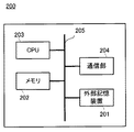
次に、図1で説明したサーバ200、据置機3、携帯機100のそれぞれのハードウェア構成について説明する。まず、サーバ200の構成について説明する。図2は、サーバ200の構成を示した図である。サーバ200は、外部記憶装置201と、メモリ202と、CPU203と、通信部204とが、バス205を介して相互に接続されている。外部記憶装置201には、据置機3との通信接続を行うための通信接続制御プログラムや後述するような映像データ、連動アプリケーション、および、これらを据置機3に配信するための配信プログラムが記憶されている。配信プログラムには、CPU203に実行させるための処理手順や各種命令等が記述されており、その中には、所定の据置機3からの配信要求信号に応じて後述の映像データおよび連動アプリケーションの配信を制御するための内容が含まれている。メモリ202は、配信プログラムを実行する場合に、外部記憶装置201より当該配信プログラムや映像データ、連動アプリケーション等のファイルを読み込むといった一時的にデータやプログラム等を記憶する内部記憶装置を示す。CPU203は、メモリ202に読み込んだプログラムを実行する演算装置や制御装置である。また、通信部204は、ネットワークを介して据置機3等と通信を行う。その他、図示は省略するが、適宜、キーボードやマウス等の入出力装置やモニタ等の表示装置を備える、あるいは接続されていてもよい。
Next, hardware configurations of the
次に、据置機3、および、これを含んだゲームシステムである据置型ゲームシステム1について説明する。
Next, the
(据置型ゲームシステムの全体構成)
図3は、据置機3を含む据置型ゲームシステム1の外観図である。図3において、据置型ゲームシステム1は、テレビジョン受像器(以下、単に「テレビ」と記載する)2、据置機3、光ディスク4、コントローラ7、およびマーカ部8を含む。本システムは、コントローラ7を用いたゲーム操作に基づいて据置機3でゲーム処理を実行するものである。
(Overall configuration of stationary game system)
FIG. 3 is an external view of the
据置機3には、当該据置機3に対して交換可能に用いられる情報記憶媒体の一例である光ディスク4が脱着可能に挿入される。光ディスク4には、据置機3において実行されるためのゲームプログラムが記憶されている。据置機3の前面には光ディスク4の挿入口が設けられている。据置機3は、挿入口に挿入された光ディスク4に記憶されたゲームプログラムを読み出して実行することによってゲーム処理を実行することが可能である。
An
据置機3には、表示装置の一例であるテレビ2が接続コードを介して接続される。テレビ2には、据置機3において実行されるゲーム処理の結果得られるゲーム画像が表示される。また、テレビ2の画面の周辺(図3では画面の上側)には、マーカ部8が設置される。マーカ部8は、その両端に2つのマーカ8Rおよび8Lを備えている。マーカ8R(マーカ8Lも同様)は、具体的には1以上の赤外LEDであり、テレビ2の前方に向かって赤外光を出力する。マーカ部8は据置機3に接続されており、据置機3はマーカ部8が備える各赤外LEDの点灯を制御することが可能である。
A
コントローラ7は、当該コントローラ7自身に対して行われた操作の内容を示す操作データを据置機3に与える入力装置である。コントローラ7と据置機3とは無線通信によって接続される。本実施形態では、コントローラ7と据置機3との間の無線通信には例えばBluetooth(ブルートゥース)(登録商標)の技術が用いられる。なお、他の実施形態においてはコントローラ7と据置機3とは有線で接続されてもよい。
The
(据置機3の内部構成)
次に、図4を参照して、据置機3の内部構成について説明する。図4は、据置機3の構成を示すブロック図である。据置機3は、CPU10、システムLSI11、外部メインメモリ12、ROM/RTC13、ディスクドライブ14、およびAV−IC15等を有する。
(Internal configuration of stationary machine 3)
Next, with reference to FIG. 4, the internal configuration of the
CPU10は、光ディスク4に記憶されたゲームプログラムを実行することによってゲーム処理を実行するものであり、ゲームプロセッサとして機能する。CPU10は、システムLSI11に接続される。システムLSI11には、CPU10の他、外部メインメモリ12、ROM/RTC13、ディスクドライブ14およびAV−IC15が接続される。システムLSI11は、それに接続される各構成要素間のデータ転送の制御、表示すべき画像の生成、外部装置からのデータの取得等の処理を行う。システムLSI11の内部構成については後述する。揮発性の外部メインメモリ12は、光ディスク4から読み出されたゲームプログラムや、フラッシュメモリ17から読み出されたゲームプログラム等のプログラムを記憶したり、各種データを記憶したりするものであり、CPU10のワーク領域やバッファ領域として用いられる。ROM/RTC13は、据置機3の起動用のプログラムが組み込まれるROM(いわゆるブートROM)と、時間をカウントするクロック回路(RTC:Real Time Clock)とを有する。ディスクドライブ14は、光ディスク4からプログラムデータやテクスチャデータ等を読み出し、後述する内部メインメモリ11eまたは外部メインメモリ12に読み出したデータを書き込む。
The
また、システムLSI11には、入出力プロセッサ11a、GPU(Graphics Processor Unit)11b、DSP(Digital Signal Processor)11c、VRAM11d、および内部メインメモリ11eが設けられる。図示は省略するが、これらの構成要素11a〜11eは内部バスによって互いに接続される。
Further, the
GPU11bは、描画手段の一部を形成し、CPU10からのグラフィクスコマンド(作画命令)に従って画像を生成する。より具体的には、GPU11bは、当該グラフィクスコマンドに従って3Dグラフィックスの表示に必要な計算処理、例えば、レンダリングの前処理にあたる3D座標から2D座標への座標変換などの処理や、テクスチャの張り込みなどの最終的なレンダリング処理を行うことで、ゲーム画像データを生成する。ここで、CPU10は、グラフィクスコマンドに加えて、ゲーム画像データの生成に必要な画像生成プログラムをGPU11bに与える。VRAM11dは、GPU11bがグラフィクスコマンドを実行するために必要なデータ(ポリゴンデータやテクスチャデータ等のデータ)を記憶する。画像が生成される際には、GPU11bは、VRAM11dに記憶されたデータを用いて画像データを作成する。
The
DSP11cは、オーディオプロセッサとして機能し、内部メインメモリ11eや外部メインメモリ12に記憶されるサウンドデータや音波形(音色)データを用いて、音声データを生成する。また、内部メインメモリ11eは、外部メインメモリ12と同様に、プログラムや各種データを記憶するものであり、CPU10のワーク領域やバッファ領域として用いられる。
The
上述のように生成された画像データおよび音声データは、AV−IC15によって読み出される。AV−IC15は、読み出した画像データをAVコネクタ16を介してテレビ2に出力するとともに、読み出した音声データを、テレビ2に内蔵されるスピーカ2aに出力する。これによって、画像がテレビ2に表示されるとともに音がスピーカ2aから出力される。
The image data and audio data generated as described above are read out by the AV-
入出力プロセッサ(I/Oプロセッサ)11aは、それに接続される構成要素との間でデータの送受信を実行したり、外部装置からのデータのダウンロードを実行したりする。入出力プロセッサ11aは、フラッシュメモリ17、無線通信モジュール18、無線コントローラモジュール19、拡張コネクタ20、およびメモリカード用コネクタ21に接続される。無線通信モジュール18にはアンテナ22が接続され、無線コントローラモジュール19にはアンテナ23が接続される。
The input / output processor (I / O processor) 11a transmits / receives data to / from components connected to the input / output processor (I / O processor) 11a or downloads data from an external device. The input /
入出力プロセッサ11aは、無線通信モジュール18およびアンテナ22を介してネットワークに接続し、ネットワークに接続される他のゲーム装置や各種サーバと通信することができる。入出力プロセッサ11aは、定期的にフラッシュメモリ17にアクセスし、ネットワークへ送信する必要があるデータの有無を検出し、当該データが有る場合には、無線通信モジュール18およびアンテナ22を介してネットワークに送信する。また、入出力プロセッサ11aは、他のゲーム装置から送信されてくるデータやダウンロードサーバからダウンロードしたデータを、ネットワーク、アンテナ22および無線通信モジュール18を介して受信し、受信したデータをフラッシュメモリ17に記憶する。CPU10はゲームプログラムを実行することにより、フラッシュメモリ17に記憶されたデータを読み出してゲームプログラムで利用する。フラッシュメモリ17には、据置機3と他のゲーム装置や各種サーバとの間で送受信されるデータの他、据置機3を利用してプレイしたゲームのセーブデータ(ゲームの結果データまたは途中データ)が記憶されてもよい。
The input /
また、入出力プロセッサ11aは、コントローラ7から送信される操作データをアンテナ23および無線コントローラモジュール19を介して受信し、内部メインメモリ11eまたは外部メインメモリ12のバッファ領域に記憶(一時記憶)する。
The input /
さらに、入出力プロセッサ11aには、拡張コネクタ20およびメモリカード用コネクタ21が接続される。拡張コネクタ20は、USBやSCSIのようなインターフェースのためのコネクタであり、外部記憶媒体のようなメディアを接続したり、他のコントローラのような周辺機器を接続したり、有線の通信用コネクタを接続することによって無線通信モジュール18に替えてネットワークとの通信を行ったりすることができる。メモリカード用コネクタ21は、メモリカードのような外部記憶媒体を接続するためのコネクタである。例えば、入出力プロセッサ11aは、拡張コネクタ20やメモリカード用コネクタ21を介して、外部記憶媒体にアクセスし、データを保存したり、データを読み出したりすることができる。
Further, an
据置機3には、電源ボタン24、リセットボタン25、およびイジェクトボタン26が設けられる。電源ボタン24およびリセットボタン25は、システムLSI11に接続される。電源ボタン24がオンにされると、据置機3の各構成要素に対して、図示しないACアダプタを経て電源が供給される。また、一旦電源がオンにされた状態で、再度電源ボタン24を押すと、低電力スタンバイモードへの移行が行われる。この状態でも、据置機3への通電は行われているため、インターネット等のネットワークに常時接続しておくことができる。なお、一旦電源がオンにされた状態で、電源をオフにしたいときは、電源ボタン24を所定時間以上長押しすることで、電源をオフとすることが可能である。リセットボタン25が押されると、システムLSI11は、据置機3の起動プログラムを再起動する。イジェクトボタン26は、ディスクドライブ14に接続される。イジェクトボタン26が押されると、ディスクドライブ14から光ディスク4が排出される。
The
次に、図5および図6を参照して、コントローラ7について説明する。なお、図5は、コントローラ7の上面後方から見た斜視図である。図6は、コントローラ7を下面前方から見た斜視図である。
Next, the
図5および図6において、コントローラ7は、ハウジング71と、当該ハウジング71の表面に設けられた複数個の操作ボタンで構成される操作部72とを備える。本実施例のハウジング71は、その前後方向を長手方向とした略直方体形状を有しており、全体として大人や子供の片手で把持可能な大きさであり、例えばプラスチック成型によって形成されている。
5 and 6, the
ハウジング71上面の中央前面側に、十字キー72aが設けられる。この十字キー72aは、十字型の4方向プッシュスイッチであり、4つの方向(前後左右)に対応する操作部分が十字の突出片にそれぞれ90°間隔で配置される。プレイヤが十字キー72aのいずれかの操作部分を押下することによって前後左右いずれかの方向を選択される。例えばプレイヤが十字キー72aを操作することによって、仮想ゲーム世界に登場するプレイヤキャラクタ等の移動方向を指示したり、複数の選択肢から選択指示したりすることができる。
A cross key 72 a is provided on the center front side of the upper surface of the
なお、十字キー72aは、上述したプレイヤの方向入力操作に応じて操作信号を出力する操作部であるが、他の態様の操作部でもかまわない。例えば、十字方向に4つのプッシュスイッチを配設し、プレイヤによって押下されたプッシュスイッチに応じて操作信号を出力する操作部を設けてもかまわない。さらに、上記4つのプッシュスイッチとは別に、上記十字方向が交わる位置にセンタスイッチを配設し、4つのプッシュスイッチとセンタスイッチとを複合した操作部を設けてもかまわない。また、ハウジング71上面から突出した傾倒可能なスティック(いわゆる、ジョイスティック)を倒すことによって、傾倒方向に応じて操作信号を出力する操作部を上記十字キー72aの代わりに設けてもかまわない。さらに、水平移動可能な円盤状部材をスライドさせることによって、当該スライド方向に応じた操作信号を出力する操作部を、上記十字キー72aの代わりに設けてもかまわない。また、タッチパッドを、上記十字キー72aの代わりに設けてもかまわない。
Note that the cross key 72a is an operation unit that outputs an operation signal in response to the above-described direction input operation of the player, but may be an operation unit of another mode. For example, four push switches may be provided in the cross direction, and an operation unit that outputs an operation signal according to the push switch pressed by the player may be provided. Further, apart from the four push switches, a center switch may be provided at a position where the cross direction intersects, and an operation unit in which the four push switches and the center switch are combined may be provided. An operation unit that outputs an operation signal in accordance with the tilt direction by tilting a tiltable stick (so-called joystick) protruding from the upper surface of the
ハウジング71上面の十字キー72aより後面側に、複数の操作ボタン72b〜72gが設けられる。操作ボタン72b〜72gは、プレイヤがボタン頭部を押下することによって、それぞれの操作ボタン72b〜72gに割り当てられた操作信号を出力する操作部である。例えば、操作ボタン72b〜72dには、1番ボタン、2番ボタン、およびAボタン等としての機能が割り当てられる。また、操作ボタン72e〜72gには、マイナスボタン、ホームボタン、およびプラスボタン等としての機能が割り当てられる。これら操作ボタン72a〜72gは、据置機3が実行するゲームプログラムに応じてそれぞれの操作機能が割り当てられる。なお、図5に示した配置例では、操作ボタン72b〜72dは、ハウジング71上面の中央前後方向に沿って並設されている。また、操作ボタン72e〜72gは、ハウジング71上面の左右方向に沿って操作ボタン72bおよび72dの間に並設されている。そして、操作ボタン72fは、その上面がハウジング71の上面に埋没しており、プレイヤが不意に誤って押下することのないタイプのボタンである。
A plurality of
また、ハウジング71上面の十字キー72aより前面側に、操作ボタン72hが設けられる。操作ボタン72hは、遠隔から据置機3本体の電源をオン/オフする電源スイッチである。この操作ボタン72hも、その上面がハウジング71の上面に埋没しており、プレイヤが不意に誤って押下することのないタイプのボタンである。
An
また、ハウジング71上面の操作ボタン72cより後面側に、複数のLED702が設けられる。ここで、コントローラ7は、他のコントローラ7と区別するためにコントローラ種別(番号)が設けられている。例えば、LED702は、コントローラ7に現在設定されている上記コントローラ種別をプレイヤに通知するために用いられる。具体的には、コントローラ7から据置機3へ送信データを送信する際、上記コントローラ種別に応じて複数のLED702のうち、種別に対応するLEDが点灯する。
A plurality of
また、ハウジング71上面には、操作ボタン72bおよび操作ボタン72e〜72gの間に後述するスピーカ(図7のスピーカ706)からの音を外部に放出するための音抜き孔が形成されている。
Further, on the upper surface of the
一方、ハウジング71下面には、凹部が形成されている。後述で明らかとなるが、ハウジング71下面の凹部は、プレイヤがコントローラ7の前面をマーカ8Lおよび8Rに向けて片手で把持したときに、当該プレイヤの人差し指や中指が位置するような位置に形成される。そして、上記凹部の傾斜面には、操作ボタン72iが設けられる。操作ボタン72iは、例えばBボタンとして機能する操作部である。
On the other hand, a recess is formed on the lower surface of the
また、ハウジング71前面には、撮像情報演算部74の一部を構成する撮像素子743が設けられる。ここで、撮像情報演算部74は、コントローラ7が撮像した画像データを解析してその中で輝度が高い場所を判別してその場所の重心位置やサイズなどを検出するためのシステムであり、例えば、最大200フレーム/秒程度のサンプリング周期であるため比較的高速なコントローラ7の動きでも追跡して解析することができる。この撮像情報演算部74の詳細な構成については、後述する。また、ハウジング71の後面には、コネクタ73が設けられている。コネクタ73は、例えばエッジコネクタであり、例えば接続ケーブルと嵌合して接続するために利用される。
An
ここで、以下の説明を具体的にするために、コントローラ7に対して設定する座標系について定義する。図5および図6に示すように、互いに直交するxyz軸をコントローラ7に対して定義する。具体的には、コントローラ7の前後方向となるハウジング71の長手方向をz軸とし、コントローラ7の前面(撮像情報演算部74が設けられている面)方向をz軸正方向とする。また、コントローラ7の上下方向をy軸とし、ハウジング71の上面(操作ボタン72a等が設けられた面)方向をy軸正方向とする。さらに、コントローラ7の左右方向をx軸とし、ハウジング71の左側面(図5では表されずに図6で表されている側面)方向をx軸正方向とする。
Here, in order to make the following description concrete, a coordinate system set for the
次に、図7および図8を参照して、コントローラ7の内部構造について説明する。なお、図7は、コントローラ7の上ハウジング(ハウジング71の一部)を外した状態を後面側から見た斜視図である。図8は、コントローラ7の下ハウジング(ハウジング71の一部)を外した状態を前面側から見た斜視図である。ここで、図8に示す基板700は、図7に示す基板700の裏面から見た斜視図となっている。
Next, the internal structure of the
図7において、ハウジング71の内部には基板700が固設されており、当該基板700の上主面上に操作ボタン72a〜72h、加速度センサ701、LED702、およびアンテナ754等が設けられる。そして、これらは、基板700等に形成された配線(図示せず)によってマイコン751等(図8、図9参照)に接続される。マイコン751は本願発明のボタンデータ発生手段の一例として、操作ボタン72a等の種類に応じた操作ボタンデータを発生させるように機能する。この仕組みは公知技術であるが、例えばキートップ下側に配置されたタクトスイッチなどのスイッチ機構による配線の接触/切断をマイコン751が検出することによって実現されている。より具体的には、操作ボタンが例えば押されると配線が接触して通電するので、この通電がどの操作ボタンにつながっている配線で発生したかをマイコン751が検出し、操作ボタンの種類に応じた信号を発生させている。
In FIG. 7, a
また、コントローラ7は、無線モジュール753(図9参照)およびアンテナ754によって、ワイヤレスコントローラとして機能する。なお、ハウジング71内部には図示しない水晶振動子が設けられており、後述するマイコン751の基本クロックを生成する。また、基板700の上主面上に、スピーカ706およびアンプ708が設けられる。また、加速度センサ701は、操作ボタン72dの左側の基板700上(つまり、基板700の中央部ではなく周辺部)に設けられる。したがって、加速度センサ701は、コントローラ7の長手方向を軸とした回転に応じて、重力加速度の方向変化に加え、遠心力による成分の含まれる加速度を検出することができるので、所定の演算により、検出される加速度データからコントローラ7の回転を良好な感度で据置機3等が判定することができる。
The
一方、図8において、基板700の下主面上の前端縁に撮像情報演算部74が設けられる。撮像情報演算部74は、コントローラ7の前方から順に赤外線フィルタ741、レンズ742、撮像素子743、および画像処理回路744によって構成されており、それぞれ基板700の下主面に取り付けられる。また、基板700の下主面上の後端縁にコネクタ73が取り付けられる。さらに、基板700の下主面上にサウンドIC707およびマイコン751が設けられている。サウンドIC707は、基板700等に形成された配線によってマイコン751およびアンプ708と接続され、据置機3から送信されたサウンドデータに応じてアンプ708を介してスピーカ706に音声信号を出力する。
On the other hand, in FIG. 8, an imaging
そして、基板700の下主面上には、バイブレータ704が取り付けられる。バイブレータ704は、例えば振動モータやソレノイドである。バイブレータ704は、基板700等に形成された配線によってマイコン751と接続され、据置機3から送信された振動データに応じてその作動をオン/オフする。バイブレータ704が作動することによってコントローラ7に振動が発生するので、それを把持しているプレイヤの手にその振動が伝達され、いわゆる振動対応ゲームが実現できる。ここで、バイブレータ704は、ハウジング71のやや前方寄りに配置されるため、プレイヤが把持している状態において、ハウジング71が大きく振動することになり、振動を感じやすくなる。
A
次に、図9を参照して、コントローラ7の内部構成について説明する。なお、図9は、コントローラ7の構成を示すブロック図である。
Next, the internal configuration of the
図9において、コントローラ7は、上述した操作部72、撮像情報演算部74、加速度センサ701、バイブレータ704、スピーカ706、サウンドIC707、およびアンプ708の他に、その内部に通信部75を備えている。
In FIG. 9, the
撮像情報演算部74は、赤外線フィルタ741、レンズ742、撮像素子743、および画像処理回路744を含んでいる。赤外線フィルタ741は、コントローラ7の前方から入射する光から赤外線のみを通過させる。レンズ742は、赤外線フィルタ741を透過した赤外線を集光して撮像素子743へ出射する。撮像素子743は、例えばCMOSセンサやあるいはCCDのような固体撮像素子であり、レンズ742が集光した赤外線を撮像する。したがって、撮像素子743は、赤外線フィルタ741を通過した赤外線だけを撮像して画像データを生成する。撮像素子743で生成された画像データは、画像処理回路744で処理される。具体的には、画像処理回路744は、撮像素子743から得られた画像データを処理して高輝度部分を検知し、それらの位置座標や面積を検出した結果を示す処理結果データを通信部75へ出力する。なお、これらの撮像情報演算部74は、コントローラ7のハウジング71に固設されており、ハウジング71自体の方向を変えることによってその撮像方向を変更することができる。この撮像情報演算部74から出力される処理結果データに基づいて、コントローラ7の位置や動きに応じた信号を得ることができる。
The imaging
コントローラ7は、3軸(x、y、z軸)の加速度センサ701を備えていることが好ましい。この3軸の加速度センサ701は、3方向、すなわち、上下方向、左右方向、および前後方向で直線加速度を検知する。また、他の実施形態においては、ゲーム処理に用いる制御信号の種類によっては、上下および左右方向(または他の対になった方向)のそれぞれに沿った直線加速度のみを検知する2軸の加速度検出手段を使用してもよい。例えば、この3軸または2軸の加速度センサ701は、アナログ・デバイセズ株式会社(Analog Devices, Inc.)またはSTマイクロエレクトロニクス社(STMicroelectronics N.V.)から入手可能であるタイプのものでもよい。加速度センサ701は、シリコン微細加工されたMEMS(Micro Electro Mechanical Systems:微小電子機械システム)の技術に基づいた静電容量式(静電容量結合式)であってもよい。しかしながら、既存の加速度検出手段の技術(例えば、圧電方式や圧電抵抗方式)あるいは将来開発される他の適切な技術を用いて3軸または2軸の加速度センサ701が提供されてもよい。
The
当業者には公知であるように、加速度センサ701に用いられるような加速度検出手段は、加速度センサの持つ各軸に対応する直線に沿った加速度(直線加速度)のみを検知することができる。つまり、加速度センサ701からの直接の出力は、その2軸または3軸のそれぞれに沿った直線加速度(静的または動的)を示す信号である。このため、加速度センサ701は、非直線状(例えば、円弧状)の経路に沿った動き、回転、回転運動、角変位、傾斜、位置、または姿勢等の物理特性を直接検知することはできない。
As known to those skilled in the art, the acceleration detection means used in the
しかしながら、加速度センサ701から出力される加速度の信号に基づいて、ゲーム装置のプロセッサ(例えばCPU10)またはコントローラのプロセッサ(例えばマイコン751)などのコンピュータが処理を行うことによって、コントローラ7に関するさらなる情報を推測または算出(判定)することができることは、当業者であれば本明細書の説明から容易に理解できるであろう。例えば、加速度センサを搭載するコントローラが静的な状態であることを前提としてコンピュータ側で処理する場合(すなわち、加速度センサによって検出される加速度が重力加速度のみであるとして処理する場合)、コントローラが現実に静的な状態であれば、検出された加速度に基づいてコントローラの姿勢が重力方向に対して傾いているか否か又はどの程度傾いているかを知ることができる。具体的には、加速度センサの検出軸が鉛直下方向を向いている状態を基準としたとき、1G(重力加速度)がかかっているか否かだけで傾いているか否かを知ることができるし、その大きさによってどの程度傾いているかも知ることができる。また、多軸の加速度センサの場合には、さらに各軸の加速度の信号に対して処理を施すことによって、各軸が重力方向に対してどの程度傾いているかをより詳細に知ることができる。この場合において、加速度センサ701からの出力に基づいて、プロセッサがコントローラ7の傾き角度のデータを算出する処理をおこなってもよいが、当該傾き角度のデータを算出する処理をおこなうことなく、加速度センサ701からの出力に基づいて、おおよその傾き具合を推定するような処理としてもよい。このように、加速度センサ701をプロセッサと組み合わせて用いることによって、コントローラ7の傾き、姿勢または位置を判定することができる。一方、加速度センサが動的な状態であることを前提とする場合には、重力加速度成分に加えて加速度センサの動きに応じた加速度を検出するので、重力加速度成分を所定の処理により除去すれば、動き方向などを知ることができる。具体的には、加速度センサ701を備えるコントローラ7がプレイヤの手で動的に加速されて動かされる場合に、加速度センサ701によって生成される加速度信号を処理することによって、コントローラ7のさまざまな動きおよび/または位置を算出することができる。なお、加速度センサが動的な状態であることを前提とする場合であっても、加速度センサの動きに応じた加速度を所定の処理により除去すれば、重力方向に対する傾きを知ることが可能である。他の実施例では、加速度センサ701は、信号をマイコン751に出力する前に内蔵の加速度検出手段から出力される加速度信号に対して所望の処理を行うための、組込み式の信号処理装置または他の種類の専用の処理装置を備えていてもよい。例えば、組込み式または専用の処理装置は、加速度センサが静的な加速度(例えば、重力加速度)を検出するためのものである場合、検知された加速度信号をそれに相当する傾斜角(あるいは、他の好ましいパラメータ)に変換するものであってもよい。
However, based on the acceleration signal output from the
他の実施形態の例では、コントローラ7の動きを検出する動きセンサとして、回転素子または振動素子などを内蔵したジャイロセンサを用いてもよい。この実施形態で使用されるMEMSジャイロセンサの一例として、アナログ・デバイセズ株式会社から入手可能なものがある。加速度センサ701と異なり、ジャイロセンサは、それが内蔵する少なくとも一つのジャイロ素子の軸を中心とした回転(または角速度)を直接検知することができる。このように、ジャイロセンサと加速度センサとは基本的に異なるので、個々の用途のためにいずれの装置が選択されるかによって、これらの装置からの出力信号に対して行う処理を適宜変更する必要がある。
In an example of another embodiment, a gyro sensor incorporating a rotation element or a vibration element may be used as a motion sensor that detects the movement of the
具体的には、加速度センサの代わりにジャイロセンサを用いて傾きや姿勢を算出する場合には、大幅な変更を行う。すなわち、ジャイロセンサを用いる場合、検出開始の状態において傾きの値を初期化する。そして、当該ジャイロセンサから出力される角速度データを積分する。次に、初期化された傾きの値からの傾きの変化量を算出する。この場合、算出される傾きは、角度に対応する値が算出されることになる。一方、加速度センサによって傾きを算出する場合には、重力加速度のそれぞれの軸に関する成分の値を、所定の基準と比較することによって傾きを算出するので、算出される傾きはベクトルで表すことが可能であり、初期化を行わずとも、加速度検出手段を用いて検出される絶対的な方向を検出することが可能である。また、傾きとして算出される値の性質は、ジャイロセンサが用いられる場合には角度であるのに対して、加速度センサが用いられる場合にはベクトルであるという違いがある。したがって、加速度センサに代えてジャイロセンサが用いられる場合、当該傾きのデータに対して、2つのデバイスの違いを考慮した所定の変換を行う必要がある。加速度検出手段とジャイロセンサとの基本的な差異と同様にジャイロセンサの特性は当業者に公知であるので、本明細書ではさらなる詳細を省略する。ジャイロセンサは、回転を直接検知できることによる利点を有する一方、一般的には、加速度センサは、本実施形態で用いるようなコントローラに適用される場合、ジャイロセンサに比べて費用効率が良いという利点を有する。 Specifically, when the inclination or posture is calculated using a gyro sensor instead of the acceleration sensor, a significant change is made. That is, when the gyro sensor is used, the inclination value is initialized in the detection start state. Then, the angular velocity data output from the gyro sensor is integrated. Next, a change amount of the inclination from the initialized inclination value is calculated. In this case, the calculated inclination is a value corresponding to the angle. On the other hand, when the inclination is calculated by the acceleration sensor, the inclination is calculated by comparing the value of the component relating to each axis of the gravitational acceleration with a predetermined reference, so the calculated inclination can be expressed by a vector. Thus, it is possible to detect the absolute direction detected using the acceleration detecting means without performing initialization. In addition, the property of the value calculated as the inclination is an angle when a gyro sensor is used, but a vector when an acceleration sensor is used. Therefore, when a gyro sensor is used instead of the acceleration sensor, it is necessary to perform predetermined conversion in consideration of the difference between the two devices with respect to the tilt data. Since the characteristics of the gyro sensor as well as the basic difference between the acceleration detecting means and the gyro sensor are known to those skilled in the art, further details are omitted in this specification. While the gyro sensor has the advantage of being able to directly detect rotation, in general, the acceleration sensor has the advantage of being more cost effective than the gyro sensor when applied to a controller as used in this embodiment. Have.
通信部75は、マイクロコンピュータ(Micro Computer:マイコン)751、メモリ752、無線モジュール753、およびアンテナ754を含んでいる。マイコン751は、処理の際にメモリ752を記憶領域として用いながら、送信データを無線送信する無線モジュール753を制御する。また、マイコン751は、アンテナ754を介して無線モジュール753が受信した据置機3からのデータに応じて、サウンドIC707およびバイブレータ704の動作を制御する。サウンドIC707は、通信部75を介して据置機3から送信されたサウンドデータ等を処理する。また、マイコン751は、通信部75を介して据置機3から送信された振動データ(例えば、バイブレータ704をONまたはOFFする信号)等に応じて、バイブレータ704を作動させる。
The
コントローラ7に設けられた操作部72からの操作信号(キーデータ)、加速度センサ701からの加速度信号(x、y、およびz軸方向加速度データ;以下、単に加速度データと記載する)、および撮像情報演算部74からの処理結果データは、マイコン751に出力される。マイコン751は、入力した各データ(キーデータ、加速度データ、処理結果データ)を無線コントローラモジュール19へ送信する送信データとして一時的にメモリ752に格納する。ここで、通信部75から無線コントローラモジュール19への無線送信は、所定の周期毎に行われるが、ゲームの処理は1/60秒を単位として行われることが一般的であるので、それよりも短い周期で送信を行うことが必要となる。具体的には、ゲームの処理単位は16.7ms(1/60秒)であり、ブルートゥース(Bluetooth;登録商標)で構成される通信部75の送信間隔は例えば5msである。マイコン751は、無線コントローラモジュール19への送信タイミングが到来すると、メモリ752に格納されている送信データを一連の操作情報として出力し、無線モジュール753へ出力する。そして、無線モジュール753は、例えばブルートゥース(登録商標)の技術に基づいて、所定周波数の搬送波を用いて操作情報で変調し、その電波信号をアンテナ754から放射する。つまり、コントローラ7に設けられた操作部72からのキーデータ、加速度センサ701からの加速度データ、および撮像情報演算部74からの処理結果データが無線モジュール753で電波信号に変調されてコントローラ7から送信される。そして、据置機3の無線コントローラモジュール19でその電波信号を受信し、据置機3で当該電波信号を復調や復号することによって、一連の操作情報(キーデータ、加速度データ、および処理結果データ)を取得する。そして、据置機3のCPU10は、取得した操作情報とゲームプログラムとに基づいて、ゲーム処理を行う。なお、ブルートゥース(登録商標)の技術を用いて通信部75を構成する場合、通信部75は、他のデバイスから無線送信された送信データを受信する機能も備えることができる。
An operation signal (key data) from the
次に、携帯機100について説明する。図10は、携帯機100の外観図である。図10において、携帯機100は、折り畳み型の携帯ゲーム装置であり、開いた状態(開状態)の携帯機100を示している。携帯機100は、開いた状態においてもプレイヤが両手または片手で把持することができるようなサイズで構成される。
Next, the
携帯機100は、下側ハウジング101および上側ハウジング111を有する。下側ハウジング101と上側ハウジング111とは、開閉可能(折り畳み可能)に連結されている。図10の例では、下側ハウジング101および上側ハウジング111は、それぞれ横長の長方形の板状で形成され、互いの長辺部分で回転可能に連結されている。通常、プレイヤは、開状態で携帯機100を使用する。また、プレイヤは、携帯機100を使用しない場合には閉状態として携帯機100を保管する。また、図10に示した例では、携帯機100は、上記閉状態および開状態のみでなく、下側ハウジング101と上側ハウジング111とのなす角度が閉状態と開状態との間の任意の角度において、連結部分に発生する摩擦力などによってその開閉角度を維持することができる。つまり、上側ハウジング111を下側ハウジング101に対して任意の角度で静止させることができる。
The
下側ハウジング101には、下側LCD(Liquid Crystal Display:液晶表示装置)102が設けられる。下側LCD102は横長形状であり、長辺方向が下側ハウジング101の長辺方向に一致するように配置される。なお、本実施形態では、携帯機100に内蔵されている表示装置としてLCDを用いているが、例えばEL(Electro Luminescence:電界発光)を利用した表示装置等、他の任意の表示装置を利用してもよい。また、携帯機100は、任意の解像度の表示装置を利用することができる。なお、詳細は後述するが、下側LCD102は、主に、内側カメラ113または外側カメラ115で撮影されている画像をリアルタイムに表示するために用いられる。
The
下側ハウジング101には、入力装置として、各操作ボタン104A〜104Kおよびタッチパネル103が設けられる。図10に示されるように、各操作ボタン104A〜104Kのうち、方向入力ボタン104A、操作ボタン104B、操作ボタン104C、操作ボタン104D、操作ボタン104E、電源ボタン104F、スタートボタン104G、およびセレクトボタン104Hは、上側ハウジング111と下側ハウジング101とを折りたたんだときに内側となる、下側ハウジング101の内側主面上に設けられる。方向入力ボタン104Aは、例えば選択操作等に用いられる。各操作ボタン104B〜104Eは、例えば決定操作やキャンセル操作等に用いられる。電源ボタン104Fは、携帯機100の電源をオン/オフするために用いられる。図10に示す例では、方向入力ボタン104Aおよび電源ボタン104Fは、下側ハウジング101の内側主面中央付近に設けられる下側LCD102に対して、左右一方側(図10では左側)の当該主面上に設けられる。また、操作ボタン104B〜104E、スタートボタン104G、およびセレクトボタン104Hは、下側LCD102に対して左右他方側(図10では右側)となる下側ハウジング101の内側主面上に設けられる。方向入力ボタン104A、操作ボタン104B〜104E、スタートボタン104G、およびセレクトボタン104Hは、携帯機100に対する各種操作を行うために用いられる。
The
なお、図10においては、操作ボタン104I〜104Kの図示を省略している。例えば、Lボタン104Iは、下側ハウジング101の上側面の左端部に設けられ、Rボタン104Jは、下側ハウジング101の上側面の右端部に設けられる。Lボタン104IおよびRボタン104Jは、携帯機100に対して、例えば撮影指示操作(シャッター操作)を行うために用いられる。さらに、音量ボタン104Kは、下側ハウジング101の左側面に設けられる。音量ボタン104Kは、携帯機100が備えるスピーカの音量を調整するために用いられる。
In FIG. 10, the operation buttons 104I to 104K are not shown. For example, the L button 104I is provided at the left end portion of the upper side surface of the
また、携帯機100は、各操作ボタン104A〜104Kとは別の入力装置として、さらにタッチパネル103を備えている。タッチパネル103は、下側LCD102の画面上を覆うように装着されている。なお、本実施形態では、タッチパネル103は、例えば抵抗膜方式のタッチパネルが用いられる。ただし、タッチパネル103は、抵抗膜方式に限らず、任意の押圧式のタッチパネルを用いることができる。また、本実施形態では、タッチパネル103として、例えば下側LCD102の解像度と同解像度(検出精度)のものを利用する。ただし、必ずしもタッチパネル103の解像度と下側LCD102の解像度とが一致している必要はない。また、下側ハウジング101の右側面には、挿入口(図10に示す破線)が設けられている。挿入口は、タッチパネル103に対する操作を行うために用いられるタッチペン117を収納することができる。なお、タッチパネル103に対する入力は、通常タッチペン117を用いて行われるが、タッチペン117に限らずプレイヤの指でタッチパネル103を操作することも可能である。
The
また、下側ハウジング101の右側面には、メモリカード118を収納するための挿入口(図10では、二点鎖線で示している)が設けられている。この挿入口の内側には、携帯機100とメモリカード118とを電気的に接続するためのコネクタ(図示せず)が設けられる。メモリカード118は、例えばSD(Secure Digital)メモリカードであり、コネクタに着脱自在に装着される。メモリカード118は、例えば、携帯機100によって撮影された画像を記憶(保存)したり、他の装置で生成された画像を携帯機100に読み込んだりするために用いられる。
Further, an insertion slot (indicated by a two-dot chain line in FIG. 10) for storing the
さらに、下側ハウジング101の上側面には、カートリッジ119を収納するための挿入口(図10では、一点鎖線で示している)が設けられている。この挿入口の内側にも、携帯機100とカートリッジ119とを電気的に接続するためのコネクタ(図示せず)が設けられる。カートリッジ119は、色変換プログラムやゲームプログラム等を記録した記録媒体であり、下側ハウジング101に設けられた挿入口に着脱自在に装着される。
Further, an insertion port (indicated by a one-dot chain line in FIG. 10) for accommodating the
下側ハウジング101と上側ハウジング111との連結部の左側部分には、3つのLED105A〜105Cが取り付けられる。ここで、携帯機100は、他の機器との間で無線通信を行うことが可能であり、第1LED105Aは、携帯機100の電源がオンである場合に点灯する。第2LED105Bは、携帯機100の充電中に点灯する。第3LED105Cは、無線通信が確立している場合に点灯する。したがって、3つのLED105A〜105Cによって、携帯機100の電源のオン/オフ状況、充電状況、および、通信確立状況をプレイヤに通知することができる。
Three LEDs 105 </ b> A to 105 </ b> C are attached to the left portion of the connecting portion between the
一方、上側ハウジング111には、上側LCD112が設けられる。上側LCD112は横長形状であり、長辺方向が上側ハウジング111の長辺方向に一致するように配置される。なお、下側LCD102と同様、上側LCD112に代えて、他の任意の方式および任意の解像度の表示装置を利用してもよい。なお、上側LCD112上を覆うように、タッチパネルを設けてもかまわない。例えば、上側LCD112には、プレイヤに各操作ボタン104A〜104Kやタッチパネル103の役割を教えるための、操作説明画面が表示される。
On the other hand, the
また、上側ハウジング111には、2つのカメラ(内側カメラ113および外側カメラ115)が設けられる。図10に示されるように、内側カメラ113は、上側ハウジング111の連結部付近の内側主面に取り付けられる。一方、外側カメラ115は、内側カメラ113が取り付けられる内側主面の反対側の面、すなわち、上側ハウジング111の外側主面(携帯機100が閉状態となった場合に外側となる面であり、図10に示す上側ハウジング111の背面)に取り付けられる。なお、図10においては、外側カメラ115を破線で示している。これによって、内側カメラ113は、上側ハウジング111の内側主面が向く方向を撮影することが可能であり、外側カメラ115は、内側カメラ113の撮影方向の逆方向、すなわち、上側ハウジング111の外側主面が向く方向を撮影することが可能である。このように、本実施形態では、2つの内側カメラ113および外側カメラ115の撮影方向が互いに逆方向となるように設けられる。例えば、プレイヤは、携帯機100からプレイヤの方を見た景色を内側カメラ113で撮影することができるとともに、携帯機100からプレイヤの反対側の方向を見た景色を外側カメラ115で撮影することができる。
The
なお、上記連結部付近の内側主面には、音声入力装置としてマイク(図11に示すマイク132)が収納されている。そして、上記連結部付近の内側主面には、マイク132が携帯機100外部の音を検知できるように、マイクロフォン用孔106が形成される。マイク132を収納する位置およびマイクロフォン用孔106の位置は必ずしも上記連結部である必要はなく、例えば下側ハウジング101にマイク132を収納し、マイク132を収納位置に対応させて下側ハウジング101にマイクロフォン用孔106を設けるようにしても良い。
Note that a microphone (a
また、上側ハウジング111の外側主面には、第4LED116(図10では、破線で示す)が取り付けられる。第4LED116は、外側カメラ115によって撮影が行われた(シャッターボタンが押下された)時点で点灯する。また、外側カメラ115によって動画が撮影される間点灯する。第4LED116によって、携帯機100による撮影が行われた(行われている)ことを撮影対象者や周囲に通知することができる。
A fourth LED 116 (shown by a broken line in FIG. 10) is attached to the outer main surface of the
また、上側ハウジング111の内側主面中央付近に設けられる上側LCD112に対して、左右両側の当該主面に音抜き孔114がそれぞれ形成される。音抜き孔114の奥の上側ハウジング111内にはスピーカが収納されている。音抜き孔114は、スピーカからの音を携帯機100の外部に放出するための孔である。
In addition, with respect to the
以上に説明したように、上側ハウジング111には、画像を撮影するための構成である内側カメラ113および外側カメラ115と、例えば撮影の際に操作説明画面を表示する表示手段である上側LCD112とが設けられる。一方、下側ハウジング101には、携帯機100に対する操作入力を行うための入力装置(タッチパネル103および各ボタン104A〜104K)と、ゲーム画面を表示するための表示手段である下側LCD102とが設けられる。したがって、携帯機100を使用する際には、プレイヤは、下側LCD102に表示される撮影画像(カメラによって撮影された画像)を見ながら、下側ハウジング101を把持して入力装置に対する入力を行うことができる。
As described above, the
次に、図11を参照して、携帯機100の内部構成を説明する。なお、図11は、携帯機100の内部構成の一例を示すブロック図である。
Next, the internal configuration of the
図11において、携帯機100は、CPU121、メインメモリ122、メモリ制御回路123、保存用データメモリ124、プリセットデータ用メモリ125、メモリカードインターフェース(メモリカードI/F)126およびカートリッジI/F134、無線通信モジュール127、ローカル通信モジュール128、リアルタイムクロック(RTC)129、電源回路130、およびインターフェース回路(I/F回路)131等の電子部品を備えている。これらの電子部品は、電子回路基板上に実装されて、下側ハウジング101(または上側ハウジング111でもよい)内に収納される。
11, the
CPU121は、所定のプログラムを実行するための情報処理手段である。本実施形態では、据置機3からダウンロードした連動アプリケーションが携帯機100内のメモリに記憶され、CPU121は、当該連動アプリケーションのプログラムを実行することによって、後述するような連動ゲーム処理を実行する。
The
CPU121には、メインメモリ122、メモリ制御回路123、およびプリセットデータ用メモリ125が接続される。また、メモリ制御回路123には、保存用データメモリ124が接続される。メインメモリ122は、CPU121のワーク領域やバッファ領域として用いられる記憶手段である。すなわち、メインメモリ122は、後述する連動ゲーム処理に用いられるプログラムや各種データを記憶する。本実施形態では、メインメモリ122として、例えばPSRAM(Pseudo−SRAM)を用いる。保存用データメモリ124は、CPU121によって実行されるプログラムや内側カメラ113および外側カメラ115によって撮影された画像のデータ等を記憶するための記憶手段である。保存用データメモリ124は、不揮発性の記憶媒体によって構成されており、例えば本実施例ではNAND型フラッシュメモリで構成される。メモリ制御回路123は、CPU121の指示に従って、保存用データメモリ124に対するデータの読み出しおよび書き込みを制御する回路である。プリセットデータ用メモリ125は、携帯機100において予め設定される各種パラメータ等のデータ(プリセットデータ)を記憶するための記憶手段である。プリセットデータ用メモリ125としては、SPI(Serial Peripheral Interface)バスによってCPU121と接続されるフラッシュメモリを用いることができる。
A
メモリカードI/F126は、CPU121に接続される。メモリカードI/F126は、コネクタに装着されたメモリカード118に対するデータの読み出しおよび書き込みを、CPU121の指示に応じて行う。本実施形態では、外側カメラ115によって撮像された画像データがメモリカード118に書き込まれたり、メモリカード118に記憶された画像データがメモリカード118から読み出されて保存用データメモリ124に記憶されたりする。
The memory card I /
カートリッジI/F134はCPU121に接続される。カートリッジI/F134は、コネクタに装着されたカートリッジ119に対するデータの読み出しおよび書き込みをCPU121の指示に従って行う。
The cartridge I /
無線通信モジュール127は、例えばIEEE802.11.b/gの規格に準拠した方式により、無線LANに接続する機能を有する。また、ローカル通信モジュール128は、所定の通信方式により同種または同様の通信方式によって通信可能な他の種類のゲーム装置との間で無線通信を行う機能を有する。無線通信モジュール127およびローカル通信モジュール128は、CPU121に接続される。CPU121は、無線通信モジュール127を用いてインターネットを介して他の機器との間でデータを送受信したり、ローカル通信モジュール128を用いて同種または他の種類のゲーム装置との間でデータを送受信したりすることができる。
The
また、CPU121には、RTC129および電源回路130が接続される。RTC129は、時間をカウントしてCPU121に出力する。例えば、CPU121は、RTC129によって計時された時間に基づいて、現在時刻(日付)等を計算することもできる。電源回路130は、携帯機100が有する電源(典型的には電池であり、下側ハウジング101に収納される)から供給される電力を制御し、携帯機100の各部品に電力を供給する。
Further, the
また、携帯機100は、マイク132およびアンプ133を備えている。マイク132およびアンプ133は、それぞれI/F回路131に接続される。マイク132は、携帯機100に向かって発声されたプレイヤの音声を検知して、当該音声を示す音声信号をI/F回路131に出力する。アンプ133は、I/F回路131から音声信号を増幅してスピーカ(図示せず)から出力させる。I/F回路131は、CPU121に接続される。
The
また、タッチパネル103は、I/F回路131に接続される。I/F回路131は、マイク132およびアンプ133(スピーカ)の制御を行う音声制御回路と、タッチパネル103の制御を行うタッチパネル制御回路とを含む。音声制御回路は、音声信号に対するA/D変換およびD/A変換を行ったり、音声信号を所定の形式の音声データに変換したりする。タッチパネル制御回路は、タッチパネル103からの信号に基づいて所定の形式のタッチ位置データを生成してCPU121に出力する。例えば、タッチ位置データは、タッチパネル103の入力面に対して入力が行われた位置の座標を示すデータである。なお、タッチパネル制御回路は、タッチパネル103からの信号の読み込み、および、タッチ位置データの生成を所定時間に1回の割合で行う。CPU121は、I/F回路131を介して、タッチ位置データを取得することにより、タッチパネル103に対して入力が行われた位置を知ることができる。
The
操作ボタン104は、上記各操作ボタン104A〜104Kから構成され、CPU121に接続される。操作ボタン104からCPU121へは、各操作ボタン104A〜104Kに対する入力状況(押下されたか否か)を示す操作データが出力される。CPU121は、操作ボタン104から操作データを取得することによって、操作ボタン104に対する入力に応じた処理を実行する。
The
内側カメラ113および外側カメラ115は、それぞれCPU121に接続される。内側カメラ113および外側カメラ115は、CPU121の指示に応じて画像を撮影し、撮影した画像データをCPU121に出力する。
The
また、下側LCD102および上側LCD112は、それぞれCPU121に接続される。下側LCD102および上側LCD112は、それぞれCPU121の指示に従って画像を表示する。
The
次に、本実施形態で想定する連動ゲームシステムの概要について説明する。本実施形態では、携帯機100で実行されるゲームのいわゆる「体験版」のアプリケーション(以下、単に「体験版」と呼ぶ)をプレイする場合を例として説明する。より具体的には、まず、サーバから据置機3に「体験版」をダウンロードして取得する。その後、今度は据置機3から携帯機100に「体験版」のアプリケーションをダウンロードして、携帯機100上で実行する場合を例とする。そして、本実施形態では、この「体験版」が、据置機3と携帯機100の双方を利用する「連動ゲーム」である。
Next, the outline | summary of the interlocking game system assumed by this embodiment is demonstrated. In the present embodiment, a case where a so-called “trial version” application (hereinafter simply referred to as “trial version”) of a game executed on the
図12〜図20は、本実施形態で想定する連動ゲームシステムにおいて表示される画面の一例である。まず、プレイヤは、据置機3を操作して、図示しない初期メニューの画面から、配信制御プログラムを起動する。配信制御プログラムが起動すると、据置機3は、インターネット経由でサーバ200との接続を確立し、サーバ200と通信可能な状態となり、配信制御プログラムの初期メニュー(図示せず)が表示される。
12 to 20 are examples of screens displayed in the linked game system assumed in the present embodiment. First, the player operates the
更に、プレイヤは、配信制御プログラムの初期メニュー上で所定の操作を行うことで、図12に示すような、「体験版」のダウンロードを行うための画面を表示させる。図12では、サーバ200からダウンロード可能な「体験版」の一覧が表示されている(当該一覧の基になるデータは、当該画面の表示に先立って、サーバ200から取得する)。そして、図12の画面において、プレイヤは、ダウンロードしたい「体験版」を選択する。本実施形態では、「三目並べ体験版」を選択したものとする。
Further, the player performs a predetermined operation on the initial menu of the distribution control program to display a screen for downloading the “trial version” as shown in FIG. In FIG. 12, a list of “trial versions” that can be downloaded from the
プレイヤが、ダウンロードしたい「体験版」を選択すると、据置機3はサーバ200と通信し、当該選択された「体験版」を構成するデータを当該サーバ200から取得する。この「体験版」を構成するデータとは、具体的には、「映像データ」と「携帯機100で実行されるアプリケーション(以下、連動アプリと呼ぶ)」の2つである(詳細は後述する)。すなわち、携帯機100で実行される「連動アプリ」と据置機3で再生される映像とが連動することで、本実施形態にかかる「連動ゲーム」が実現される。また、サーバから当該「体験版」を構成するデータを取得している間は、図13に示すような画面が据置機3に表示される。この画面には、携帯機100の準備を促すメッセージも表示されている。
When the player selects a “trial version” that he / she wants to download, the
据置機3においてダウンロードが終了すると、図14(A)に示すように、サーバ200からのダウンロードが完了した旨のメッセージが表示される。この画面では、携帯機100の準備を促すメッセージも表示されている。そして、プレイヤは、携帯機100を起動し、図14(B)に示すような携帯機100に表示される初期メニューから、ゲームをダウンロードして遊ぶためのアプリケーション(図14(B)では「ダウンロードプレイ」)を起動する。当該アプリケーションが起動すると、据置機3と携帯機100との間で無線通信を行うための接続が確立される(この際、据置機3とサーバ200との接続は切断される)。
When the download is completed in the
据置機3と携帯機100との接続が確立すると、据置機3に図15(A)で示すような、配信中であることを示す画面が表示される。また、携帯機100には、図15(B)で示すように、据置機3からダウンロード可能なアプリケーション(この場合は「三目並べ体験版」)が表示される。プレイヤが、携帯機100を操作して当該「三目並べ体験版」を選択すると、据置機3からのダウンロードが始まり、携帯機100には、図16(B)に示すような、ダウンロード状況を示す画面が表示される(このとき、据置機3の画面は図16(A)に示すように、配信中の画面が表示されたままである)。
When the connection between the
そして、据置機3から携帯機100への「三目並べ体験版」のダウンロードが終了すると、据置機3には図17(A)に示すようなダウンロード終了を示す画面が表示され、携帯機100にも図17(B)に示すようなダウンロード終了を示す画面が表示される。
Then, when the download of the “Tsubame Trial Trial Version” from the
その後、携帯機100において自動的に「三目並べ体験版」が起動する。あるいは、ダウンロード終了後に、「三目並べ体験版」を起動するための確認画面を表示するようにしてもよい。なお、本実施形態では、当該「三目並べ体験版」の起動に際して、一旦据置機3と携帯機100との通信を切断し、再度接続を確立する処理が行われる。つまり、「三目並べ体験版」の実行に際して、ゲームの実行に適した通信が行えるように再度接続し直している。そのため、「三目並べ体験版」の起動直後は、図18(A)および(B)に示すような、接続を再度確立していることを示す画面が表示される。
Thereafter, the “Tic-tac-ordered trial version” is automatically activated on the
据置機3と携帯機100との接続が確立すると、携帯機100の下側LCD102には、図19(B)で示すような「三目並べ体験版」の初期メニューが表示される。一方、据置機3と接続されているテレビ2には、図19(A)に示すような映像が再生される。図19(A)では、女性が「三目並べ体験版」の紹介を行うような内容のイントロ映像が再生されている。当該映像は、上記サーバ200から据置機3にダウンロードされた「映像データ」に基づくものである。
When the connection between the
図19(B)の画面で、プレイヤが「三目並べ体験版」の開始を選ぶと、三目並べゲームが開始する。ここで、当該三目並べのルールについて簡単に説明する。このゲームは、図20(B)に示すような、縦3×横3の9つのマスに、プレイヤと携帯機100のCPU121とで交互に1つずつ駒を置いていき、先に縦横斜めのいずれかに同じ駒を3つ並べた方が勝ちとなるゲームである。また、本実施形態では、プレイヤが先攻、CPU121が後攻であり、プレイヤの駒を「○」、CPU121の駒を「×」で示す。プレイヤは、任意のマスをタッチペン117などでタッチすれば、そこに自分の駒を置くことができる。
When the player chooses to start the “Tic-tac-order trial version” on the screen of FIG. 19B, the tic-tac-toe game starts. Here, the rule of tic-tac-toe will be briefly described. In this game, as shown in FIG. 20 (B), the player and the
そして、本実施形態では、携帯機100で行われたプレイヤの操作や「三目並べ」ゲームの進行状況に応じて、据置機3で異なった映像が再生される。つまり、携帯機100におけるアプリケーションの実行状況に連動して、据置機3で所定の映像が再生されるという処理が実行される。例えば、プレイヤが駒を置いた時に、据置機3は「そこでいいの?」という台詞を女性が話す映像を再生する。また、プレイヤが勝ったときは、据置機3は、「負けちゃった」と女性が話す映像を再生する。以下、当該処理の概要について説明する。
In the present embodiment, different videos are played on the
まず、上記据置機3でサーバ200からダウンロードされた映像データの構成について説明する。図21は、当該映像データの構成の一例を説明するための図である。サーバ200から据置機3にダウンロードされた映像データは、ゲームの進行状況に応じた複数の映像が含まれている。各映像は、あるフレーム群で一連となる映像として構成されている。図21では、例えば、0001フレーム〜0100フレーム目までで、上述したような、ゲームを紹介するような内容のイントロ映像が構成されている。また、0201フレーム〜0300フレーム目までは、ゲームの操作方法を説明するためのガイド用の映像が構成されている。
First, the configuration of video data downloaded from the
次に、上記のような映像データの再生とゲーム進行状況との連動処理に関して説明する。本実施形態では、携帯機100が、ゲームの進行状況やプレイヤの操作内容に応じて、再生させたい映像のフレーム番号を据置機3に通知することで、ゲームの状況に応じた映像を据置機3に再生させる。例えば、上記のようなイントロ映像の場合は、携帯機は、三目並べゲームが起動した直後のタイミングで、再生開始フレーム番号として0001、再生終了フレームとして0100を指定したデータを据置機に送信する。これに応じて、据置機は、映像データのうち、0001〜0100フレーム目までを再生する処理を実行する。これにより、連動ゲーム開始時は、テレビ2にイントロ映像である、0001〜0100フレーム目で構成される映像が再生されることになる。
Next, a description will be given of the interlocking process between the video data reproduction and the game progress as described above. In the present embodiment, the
同様に、三目並べゲームのプレイ中に、携帯機100は適宜、開始フレームと終了フレームを指定するデータを送信し、据置機3は、当該送信された開始フレームから終了フレームにかかる映像の再生処理を実行する。例えば、本ゲームは上述のように交互に駒を配置するゲームだが、この場合、プレイヤが駒を置く操作を行ったタイミングで、「そこでいいの?」という台詞を女性が話す映像を構成するフレーム(開始フレームと終了フレーム:図21ではNo.12で示されるフレーム)を指定するデータを据置機3に送信する。これに応じて、据置機3では、当該指定されたフレームにかかる映像を再生する処理を実行する。
Similarly, during the play of the tic-tac-toe game, the
その後、CPU側の手番で、CPU121が駒をおく処理を行うタイミングでは、携帯機100は、「私はここに・・・」という台詞を話しながら女性が携帯機100を操作するような映像を構成するフレーム(図21では、No.16の映像を構成するフレーム)を指定するデータを据置機3に送信する。また、勝敗が決したタイミングにおいて、プレイヤが勝った場合は、携帯機100は、「負けちゃった」と女性が話す映像を構成するフレーム(図21では、No.17の映像のフレーム)を指定して送信し、CPU121が勝った場合は、「勝ったよ!」と喜びながら話す映像のフレーム(図21ではNo.18の映像のフレーム)を指定するデータを送信する。
After that, at the timing when the
なお、本実施形態では、同じ場面について複数の映像を用意している場面もある。図21の例で言うと、No.7〜9の3つの映像は、いずれも、プレイヤが1手目の駒を置いたときに再生される映像として作成されたものである。そして、本実施形態では、このように1つの場面について複数の映像が用意されている場合は、この複数の映像の中から一つがランダムに選択されて再生される。 In this embodiment, there are scenes where a plurality of videos are prepared for the same scene. In the example of FIG. The three videos 7-9 are all created as videos that are played back when the player places the first piece. In this embodiment, when a plurality of videos are prepared for one scene as described above, one of the plurality of videos is randomly selected and reproduced.
このように、本実施形態は、プレイヤの操作やゲームの進行状況に応じて、再生させたいフレームを指定して据置機3に通知することで、ゲーム展開に連動した映像を据置機3に再生させ、テレビ2に表示する。これにより、上記のような対戦形式のゲームの場合は、テレビ2で再生されている女性と対戦しているようなプレイ感をプレイヤに提供する事が可能となる。
As described above, according to the present embodiment, a frame to be reproduced is designated and notified to the
もちろん、上記のような対戦形式のゲームに適用することに限らず、本発明は、他の形式のゲームにも適用できる。つまり、携帯機100で実行されるゲームについての拡張画面としてテレビ2を利用することができ、補助的な情報等をテレビ2に表示することも可能である。例えば、アクションゲームやRPG等で、ゲーム内の場面に応じて、ゲームのヒントとなるような映像をテレビ2に表示することも可能である。
Of course, the present invention is not limited to the game of the battle type as described above, and the present invention can also be applied to other types of games. That is, the
また、そのほか、携帯機で実行されるゲームの仮想空間内で、スクリーンあるいはモニタオブジェクトが存在するような場合を想定する。例えば、RPGの1シーンにおいて、壁に大きなスクリーンが備えられたビルが存在するような場面が、携帯機100の下側LCD102に表示されている状況の場合(但し、画面上では、小さく表示されており、当該スクリーンで何が再生されているのかはプレイヤには認識できない状態)に、このスクリーンで再生されている映像を据置機3に再生させることで、ゲームの臨場感等をより高めることも可能となる。また、ゲーム内に登場するキャラクターに関する情報等(プロフィール等)を、据置機3に映像として再生することで、ゲームの進行と共にプレイヤにそのキャラクターについてより深く知ってもらうことができ、キャラクタに対する感情移入をしやすくする等でゲームの興趣性を高めることも可能となる。
In addition, it is assumed that a screen or a monitor object exists in the virtual space of a game executed on the portable device. For example, in the case where a scene in which a building with a large screen is present on the wall is displayed on the
このように、本実施形態では、サーバ200から据置機3に、映像データと、携帯機100で実行される連動アプリをダウンロードし、更に、据置機3から携帯機100に、連動アプリのみを送信している。そして、携帯機100での連動アプリの実行内容等に連動して、ダウンロードした映像データの再生を据置機3で行っている。これにより、据置機と携帯機とを連動させた今までにないゲーム等のアプリケーションを配信することが可能となる。
As described above, in the present embodiment, the video data and the linked app executed on the
次に、本実施形態にかかるシステムによって実行される連動ゲーム配信処理および連動ゲーム処理の詳細を説明する。まず、本システムにおけるサーバ200、据置機3、携帯機100に記憶されるデータについて説明する。
Next, details of the linked game distribution process and the linked game process executed by the system according to the present embodiment will be described. First, data stored in the
まず、サーバ200に記憶されるデータについて説明する。図22は、サーバ200のメモリ202のメモリマップを示す図である。図22において、メモリ202は、プログラム記憶領域2021およびデータ記憶領域2023を含む。プログラム記憶領域2021には、配信制御プログラム2022が記憶される。当該プログラムは、据置機3からの要求に応じて、所定の連動アプリケーションおよび映像データ(本実施形態では、上記の「体験版」である)を据置機3に送信するためのプログラムである。また、データ記憶領域2023には、配信用アプリセット24が複数記憶される。各配信用アプリセット2024は、映像データ2025と連動アプリケーション2026で構成されている。映像データ2025は、上述したような、据置機3で再生される映像のデータであり、所定の符号化方式(但し、据置機3で再生可能な方式)で予めエンコードされたデータである。連動アプリケーション2026は、最終的に携帯機100上で実行されるアプリケーション(本実施形態では、三目並べゲーム)のデータである。連動アプリケーション2026には、携帯機100のCPU121に三目並べゲームを実行させるためのプログラムである連動ゲームプログラム2027と、画像データや音声データ等、ゲームで用いる各種データを含む連動ゲームデータ2028が含まれる。なお、プログラム記憶領域2021およびデータ記憶領域2023のデータは、外部記憶装置201に記憶され、配信制御プログラム2022の実行時にメモリ202に転送されて記憶される。
First, data stored in the
次に、据置機3に記憶されるデータについて説明する。図23は、据置機3の外部メインメモリ12のメモリマップを示す図である。図23において、外部メインメモリ12は、プログラム記憶領域401およびデータ記憶領域405を含む。プログラム記憶領域401のデータは、フラッシュメモリ17に記憶されており、各プログラム実行時に外部メインメモリ12に転送されて記憶される。
Next, data stored in the
プログラム記憶領域401には、ランチャープログラム402、配信制御プログラム403が記憶されている。ランチャープログラム402は、据置機3を起動した際に表示される初期メニュー(図示せず)を制御するためのプログラムである。配信制御プログラム403は、当該初期メニューから選択可能なアプリケーションであり、上記図12で示したような、「体験版」のサーバ200からのダウンロードや、携帯機100への「体験版」の送信制御を行うためのプログラムである。また、当該配信制御プログラム403には、携帯機100からの再生指示に基づき、サーバ200から取得した映像データ406を再生するための映像再生制御プログラム404が含まれている。
In the
データ記憶領域405には、映像データ406、連動アプリケーション407、据置側制御データ410、携帯側制御データ[受信]411が記憶される。データ記憶領域405に記憶されるこれらのデータのうち、映像データ406および連動アプリケーション407は、サーバ200からダウンロードされたものが記憶されたものである。つまり、上記サーバ200に記憶されている映像データ2025および連動アプリケーション2026と同じ内容である。
The
据置側制御データ410は、連動アプリの実行中、据置機3から携帯機100に毎フレーム(本実施形態では1/60秒毎に)送信されるデータであり、据置機3における映像の再生状況等を示すデータである。図24は、据置側制御データ410のデータ構造の一例を示した図である。据置側制御データ410は、指示種類データ4100と開始フレームデータ4101と終了フレームデータ4102と総フレーム数データ4103とカレントフレーム番号データ4104と再生モードフラグ4105と再生中フラグ4106と要求受付可能フラグ4107の集合から構成される。
The
指示種類データ4100は、携帯機100から据置機3に指示する内容を示すデータである。すなわち、据置機3は、携帯機100からどのような指示を受けているかを示す。本実施形態では、具体的には、「映像再生」か「ゲーム終了」かを示すデータのいずれかが設定されるものとする。
The
開始フレームデータ4101は、再生対象の映像の開始フレーム番号を示し、終了フレームデータ4102は、再生対象の映像の終了フレーム番号を示すデータである。総フレーム数データ4103は、サーバ200からダウンロードした映像データ2025全体の総フレーム数を示す。例えば、上述した図21の映像の構成例では、総フレーム数は”2100”となる。カレントフレーム番号データ4104は、現在据置機3で再生されているフレームの番号を示すデータである。
The
再生モードフラグ4105は、現在の再生モードを示すデータである。再生モードには、指定された映像を一度だけ再生して終わる「ワンプレイ」モードと、繰り返し再生する「ループ」モードの2つがあり、後述する携帯側制御データ508において、いずれかのモードが携帯機100から指定される。
The
再生中フラグ4106は、現在映像が再生されているか否かを示すフラグである。再生中はオンに設定され、映像が再生されていないときはオフに設定される。
The playing
要求受付可能フラグ4107は、後述する携帯側制御データ508に含まれる携帯機100からの映像再生指示を据置機3が受け付けることができるか否かを示すフラグである。指示を受け付けることが可能なときはオンが設定され、指示を受け付けることができないときは、オフに設定される。なお、指示を受け付けることができない場合は、例えば、据置機3において、映像の再生準備を行っているような場合(映像データの読み込み処理中や開始フレームのシーク中等)である。
The
携帯側制御データ[受信]411は、携帯機100から送信されてくる携帯側制御データ508(後述の図26)を受信したものである。据置機3は、この内容に基づいて、映像データ406の所定のフレームからの再生を開始する。なお、以下では、携帯側制御データ[受信]411に含まれる各データの参照符号については、携帯機100上に記憶されているものと区別するため、例えば、”開始フレームデータ5082j”のように、末尾に”j”を付けて区別する。
The mobile-side control data [Reception] 411 is obtained by receiving mobile-side control data 508 (FIG. 26 described later) transmitted from the
次に、携帯機100に記憶されるデータについて説明する。図25は、携帯機100のメインメモリ122のメモリマップを示す図である。図25において、メインメモリ122は、プログラム記憶領域501およびデータ記憶領域505を含む。なお、プログラム記憶領域501のデータのうち、ランチャープログラム502およびダウンロードプログラム503は、保存用データメモリ124に記憶されており、各プログラム実行時にメインメモリ122に転送されて記憶される。一方、連動ゲームプログラム504は、据置機3からダウンロードされた連動アプリケーション407に含まれる連動ゲームプログラム408が記憶されたものである。
Next, data stored in the
データ記憶領域505には、連動ゲームデータ506、操作データ507、携帯側制御データ508、据置側制御データ[受信]509等が記憶される。連動ゲームデータ506は、据置機3からダウンロードされた連動アプリケーション407に含まれる連動ゲームデータ409が記憶されたものである。操作データ507は、プレイヤが携帯機100に対して行った操作内容を示すデータである。本実施形態では、1/60秒間隔でその内容が更新されるものとする。
The
携帯側制御データ508は、連動ゲームの実行中、携帯機100から据置機3に対して、必要に応じて送信されるデータであり、上述したような据置機3で再生される映像を指定し、再生させるためのデータである。
The mobile-
図26は、携帯側制御データ508のデータ構造の一例を示した図である。携帯側制御データ508は、指示種類データ5081、開始フレームデータ5082と終了フレームデータ5083と再生モードフラグ5084の集合から構成される。
FIG. 26 is a diagram showing an example of the data structure of the mobile
指示種類データ5081は、携帯機100から据置機3に指示する内容を示すデータであり、本実施形態では、具体的には、「映像再生」か「ゲーム終了」かを示すデータのいずれかが設定されるものとする。
The
開始フレームデータ5082は、据置機3で再生させたい映像の開始フレーム番号を示し、終了フレームデータ5083は、据置機3で再生させたい映像の終了フレーム番号を示すデータである。
The
再生モードフラグ5084は、据置機に映像を再生させる際の再生モードを指定するためのデータである。上述したような、「ワンプレイ」モードと「ループ」モードのいずれかが指定される。
The
図25に戻り、据置側制御データ[受信]509は、据置機3から毎フレーム(1/60秒毎に)送信される上記据置側制御データ410を受信したものである。そのため、データ構造は、上記図24で示した据置側制御データ410の構造と同様である(なお、以下では、据置側制御データ[受信]509に含まれる各データの参照符号については、据置機3上に記憶されているものと区別するため、例えば、”開始フレームデータ4101j”のように、同じ参照符号で末尾に”j”を付けて区別する)。上記のように、本実施形態では、据置機3から携帯機100へ1/60秒に1回の割合で据置側制御データが送られてくるため、据置側制御データ[受信]509はこの割合で更新される。本実施形態においては、据置側制御データ[受信]509には、最新の(最後に取得された)据置側制御データのみが記憶されればよい。
Returning to FIG. 25, the stationary control data [Reception] 509 is obtained by receiving the
次に、図27〜図37を参照して、本実施形態にかかるシステムによって実行される連動ゲーム処理について説明する。図27は本システムによって実行される連動ゲーム処理の全体処理を示すフローチャートである。図27では、右から順番に、サーバ200の処理、据置機3の処理、携帯機100の処理フローを示している。図27において、まず、据置機3において、配信制御プログラム403が起動される(ステップS1)。
Next, a linked game process executed by the system according to the present embodiment will be described with reference to FIGS. FIG. 27 is a flowchart showing the entire linked game process executed by this system. In FIG. 27, the processing flow of the
次に、据置機3において、配信可能ソフト(ダウンロード可能ソフト)の一覧が表示される(ステップS2)。より具体的には、据置機3のCPU10は、サーバ200に配信可能ソフトの情報を要求する。これに応じて、サーバ200では、配信可能ソフトの情報を据置機3に送信する処理が実行される(ステップS3)。そして、据置機3では、当該情報が受信され、当該情報に基づいて配信可能ソフト一覧が生成されて表示される。
Next, a list of distributable software (downloadable software) is displayed on the stationary device 3 (step S2). More specifically, the
次に、据置機3において、プレイヤの操作が受け付けられ、一覧の中からダウンロードするソフトの選択操作が行われたか否かが判定される(ステップS4)。その結果、選択されていないと判定されたときは(ステップS4でNO)、操作が行われるまでステップS4の判定を繰り返す。一方、選択が行われたと判定されたときは(ステップS4でYES)、据置機3において、当該選択されたソフトの配信を要求するデータが生成され、サーバ200に送信される(ステップS5)。
Next, in the
サーバ200においては、上記配信可能ソフトの情報を据置機3に送信した後、据置機3から配信要求があったか否かの判定が行われる(ステップS6)。ステップS6の判定の結果、配信要求がないと判定されれば(ステップS6でNO)、ステップS6の判定が繰り返される(すなわち、配信要求の待ち受け状態となる)。
In the
一方、ステップS6の判定の結果、配信要求が送られてきたと判定されたときは(ステップS6でYES)、サーバ200と据置機3との間で映像データ2025を送受信する処理が実行される(ステップS7、S8)。映像データ2025の送受信が終われば、続いて、サーバ200と据置機3との間で、連動アプリケーション2026の送受信処理が実行される(ステップS9,S10)。
On the other hand, if it is determined as a result of the determination in step S6 that a distribution request has been sent (YES in step S6), processing for transmitting / receiving
連動アプリケーション2026の送受信処理が終われば、次に、据置機3において、携帯機の準備を促す画面(上記図14(A)参照)をテレビ2に表示する処理が実行される(ステップS11)。その後、据置機3では、携帯機100の検出処理が実行される(ステップS15)。例えば、据置機3のCPU10は、携帯機100からの接続要求を検出したか否かを判定し、その結果、検出していなければ(ステップS15でNO)、携帯機100からの接続要求の検出を繰り返す。検出できれば(ステップS15でYES)、据置機3に保存されている連動アプリケーション407を携帯機100に送信する処理が実行される(ステップS17)。
When the transmission / reception process of the
一方、携帯機100では、まず、プレイヤの所定の操作(電源投入など)に基づき、ランチャープログラム502が実行されて携帯機100の初期メニューの表示処理が実行される(ステップS12)。
On the other hand, in the
次に、携帯機100において、初期メニューからダウンロード用のプログラム503が起動され、据置機3との通信処理(上記図14(B)参照)が選択されたか否かが判定される(ステップS13)。当該判定の結果、据置機3との通信処理が選択されていなければ(ステップS13でNO)、当該通信処理が選択されるまでステップS13の処理が繰り返される。また図示しないが、他の項目が選択された場合は、当該選択された項目に対応するプログラムや設定画面等が起動される。当該通信処理が選択されたときは(ステップS13でYES)、据置機3の検出処理が実行される(ステップS14)。これは、例えば、据置機3から定期的に発信されるビーコンを検出すること等で検出処理が実行される。据置機3が検出されなければ(ステップS14でNO)、ステップS14の検出処理が繰り返され、据置機3が検出されたときは(ステップS14でYES)、携帯機100において、据置機3との間で接続を確立するための処理が実行される。その後、連動アプリケーション407を据置機3から受信する処理が実行される(ステップS16:上記図15(B)、図16(B)参照)。
Next, in the
据置機3と携帯機100との間で連動アプリケーション407の送受信処理が終了すると、携帯機100においては、携帯側連動処理(ステップS18)が実行され、据置機3では、据置側連動処理(ステップS19)が実行されることによって、連動ゲームが実行される。
When the transmission / reception process of the interlocking
次に、上記ステップS18およびS19にかかる連動ゲーム処理の詳細について説明する。図28、図32〜図35は、上記ステップS18で示した携帯側連動処理の詳細を示すフローチャートである。図28において、まず、連動ゲームの初期メニューが生成され、下側LCD102に表示される(ステップS31)。 Next, details of the interlocking game process in steps S18 and S19 will be described. 28 and FIGS. 32 to 35 are flowcharts showing details of the portable-side interlocking process shown in step S18. In FIG. 28, first, an initial menu of the linked game is generated and displayed on the lower LCD 102 (step S31).
次に、ゲーム開始直後のイントロ映像を据置機3に再生させるための携帯側制御データ508の生成が実行される(ステップS32)。上述した図21の映像データの構成を例にすると、イントロ映像は、0001フレーム〜0100フレームである。そのため、CPU121は、指示種類データ5081に「再生」、開始フレームデータ5082に”0001”、終了フレームデータ5083に”0100”、再生モードフラグ5084に”ワンプレイ”(つまり、一度だけしか再生させない)が設定された携帯側制御データ508を生成する。
Next, generation of the mobile
次に、ステップS32で生成された携帯側制御データ508を据置機3に送信するための、制御データ送信処理が実行される(ステップS33)。この処理では、上記携帯側制御データ508の送信を行うと共に、当該携帯側制御データ508で示される再生指示内容が据置機3で正常に受け付けられ、指定した映像の再生が据置機3上で開始されたか否かを確認する処理も行われる。当該処理の概要を説明すると、毎フレーム据置機3から携帯機100に送信されてくる据置側制御データ410で示される再生状況(開始・終了フレームや再生中か否か等の情報)と、上記送信した携帯側制御データ508で示される再生指示内容とをマッチングして、一致していれば、正常に再生が開始されたと判断する。一方、不一致であれば、再生が開始されていないとして、所定の時間後に上記携帯側制御データ508を再送信するという処理が行われる。これは、携帯機100から送信した再生指示の内容が、何らかの原因で据置機3で受け付けられないことにより、携帯機100の処理状況に連動した映像が据置機3で再生されない状況となることを防ぐために、上記のように、据置機3で正常に再生開始されたか否かを確認するものである。
Next, a control data transmission process for transmitting the portable
図29〜図30は、上記ステップS33で示した制御データ送信処理の詳細を示すフローチャートである。図29において、まず、据置機3から毎フレーム送信されてくる、据置側制御データ[受信]509が参照され、要求受付可能フラグ4107jが取得される(ステップS91)。
29 to 30 are flowcharts showing details of the control data transmission process shown in step S33. In FIG. 29, first, stationary control data [reception] 509 transmitted from the
次に、上記要求受付可能フラグ4107jがオンか否かが判定される(ステップS92)。当該判定の結果、オンでないと判定されたときは(ステップS92でNO)、据置機3で再生指示を受け付けることができない状態と考えられる。このときは、次に、ステップS92の判定が行われてから2秒経過したか否かが判定される(ステップS93)。その結果、2秒経過していないと判定されたときは(ステップS93でNO)、2秒経過するまでステップS93の判定が繰り返される。2秒経過すれば(ステップS93でYES)、上記ステップS91の処理が再度実行される。
Next, it is determined whether the request acceptance flag 4107j is on (step S92). As a result of the determination, when it is determined that the signal is not on (NO in step S92), it is considered that the
一方、ステップS92の判定の結果、要求受付可能フラグ4107jがオンと判定されたときは(ステップS92でYES)、続いて、携帯側制御データ508を据置機3に送信する処理が実行される(ステップS94)。次に、据置側制御データ[受信]509から開始フレームデータ4101jが取得される(ステップS95)。続いて、当該開始フレームデータ4101jと、先ほど送信した携帯側制御データ508の開始フレームデータ5082とが一致するか否かが判定される(図30のステップS96)。当該判定の結果、一致していないと判定されたときは(ステップS96でNO)、携帯機100から送信した命令が据置機3において反映されていないと考えられる。この場合は、上記携帯側制御データ508の再送信が必要となるかもしれないため、次に、携帯側制御データ508を送信してから2秒が経過したか否かが判定される(ステップS103)。当該判定の結果、2秒経過していないときは(ステップS103でNO)、上記ステップS95に戻り、再度、据置側制御データ[受信]509の内容を取得する処理が実行される。上記のように、据置機3からは、1フレーム(1/60秒)という短い時間間隔で据置側制御データ410が送信されてくるため、例えば1度目の開始フレームの一致判定で不一致と判定されたとしても、数フレーム後の判定においては、据置側制御データ[受信]509の内容が更新されており、ここでの判定で一致していると判定されれば、映像の連動再生という観点では問題がない。一方、ステップS103の判定の結果、2秒経過していれば(ステップS103でYES)、上記ステップS91に戻り、処理が繰り返される。つまり、携帯側制御データ508の送信後、2秒経過しても再生指示内容と再生状況とが一致していないようであれば、上記携帯側制御データ508の再送信が試みられることになる。
On the other hand, as a result of the determination in step S92, when it is determined that the request acceptance flag 4107j is on (YES in step S92), a process of transmitting the
一方、ステップS96の判定の結果、開始フレームが一致していると判定されたときは(ステップS96でYES)、次に、据置側制御データ[受信]509から終了フレームデータ4102jが取得される(ステップS97)。続いて、当該終了フレームデータ4102jと、先ほど送信した携帯側制御データ508の終了フレームデータ5083とが一致するか否かが判定される(ステップS98)。当該判定の結果、一致していないと判定されたときは(ステップS98でNO)、上記ステップS103の処理が実行される。
On the other hand, if it is determined in step S96 that the start frames match (YES in step S96), then end frame data 4102j is acquired from stationary control data [receive] 509 ( Step S97). Subsequently, it is determined whether or not the end frame data 4102j matches the
一方、ステップS98の判定の結果、終了フレームが一致していると判定されたときは(ステップS98でYES)、次に、据置側制御データ[受信]509から再生モードフラグ4105jが取得される(ステップS99)。続いて、当該再生モードフラグ4105jと、先ほど送信した携帯側制御データ508の再生モードフラグ5084とが一致するか否かが判定される(ステップS100)。当該判定の結果、一致していないと判定されたときは(ステップS100でNO)、上記ステップS103の処理が実行される。
On the other hand, if it is determined in step S98 that the end frames match (YES in step S98), the reproduction mode flag 4105j is acquired from the stationary control data [receive] 509 ( Step S99). Subsequently, it is determined whether or not the reproduction mode flag 4105j matches the
一方、ステップS100の判定の結果、再生モードが一致していると判定されたときは(ステップS100でYES)、次に、据置側制御データ[受信]509から再生中フラグ4106jが取得される(ステップS101)。続いて、当該再生中フラグ4106jがオンであるか否かが判定される(ステップS102)。当該判定の結果、オンでないと判定されたときは(ステップS102でNO)、据置機3において映像の再生がまだ開始されていないと考えられる。この場合は、上記ステップS103の処理が実行される。一方、再生中フラグがオンと判定されたときは(ステップS102でYES)、据置機3において映像の再生が正常に開始したと考えられるため、当該制御データ送信処理は終了する。
On the other hand, as a result of the determination in step S100, if it is determined that the reproduction modes match (YES in step S100), next, the reproduction flag 4106j is acquired from the stationary control data [Reception] 509 ( Step S101). Subsequently, it is determined whether or not the playing flag 4106j is on (step S102). As a result of the determination, when it is determined that the signal is not on (NO in step S102), it is considered that the video reproduction has not yet started in the
このような制御データ送信処理を実行することによる、携帯機100からの再生指示から据置機3における映像の再生開始までの流れは、図31に示すような流れとなる。図31においては、時間軸を縦方向としており、図の左側が携帯機100、右側が据置機3における処理を示している。そして、据置機3から携帯機100には、毎フレーム、再生状況を示すデータ(据置側制御データ410)が送信されている。図31において、まず、時間T1において、携帯機100から再生指示(携帯側制御データ508)が送信される(時間T1では、据置機3の要求受付可能フラグ4107はオンの状態である)。当該再生指示は時間T2で据置機3に到達する。しかし、時間T1から時間T2までの間である状態<1>においては、再生指示が据置機3にまだ届いていないため、携帯機100から送信した再生指示と据置機3から送信されてくる再生状況とは一致しない。そのため、状態<1>においては、携帯機100は2秒経過するまで図29のステップS95〜S102の処理を繰り返し行い、携帯機110から送信した再生指示と、据置機3から送信されてくる再生状況とが一致するか判定を行う。2秒間一致しない状態が続いたときは、要求受付可能フラグ4107jの判断(ステップS91)に戻るという処理を行うことになる。
By executing such control data transmission processing, the flow from the reproduction instruction from the
次に、据置機3において、時間T2で再生指示が到達したため、当該再生指示に基づいて映像の再生準備が開始される。そして、当該再生準備が終わり、実際に映像の再生が開始するのが時間T3であるとする。この場合、時間T2から時間T3までの間である状態<2>においては、据置機3は映像の再生準備中であるため、据置機3から携帯機100に送信されてくる据置側制御データ410の中の要求受付可能フラグ4107はオフに設定されている(据置機3での処理については後述する)。そのため、携帯機100では、据置機3へ再生指示を送信することができず、2秒待ってから、要求受付可能フラグ4107jの判断(ステップS91)に戻ることになる。
Next, in the
そして、時間T3で据置機3での映像の再生が開始されると、時間T3以降である状態<3>においては、携帯機100から送信した再生指示の内容と据置機3から送信される再生状況とが一致するため、携帯機100において、映像の再生が正常に開始されたと判定することになる。
When the reproduction of the video on the
図28に戻り、ステップS33の処理(つまり、イントロ映像の再生が正常に開始された状態)が終われば、次に、据置機3での映像の再生が終了したか否かが確認される(ステップS34)。具体的には、据置側制御データ[受信]509を参照し、再生中フラグ4106jがオフになったか否かを判定することで据置機3における映像の再生が終了したか否かが判定される。当該判定の結果、映像の再生がまだ終了していないと判定されたときは(ステップS34でNO)、再生が終了するまで、ステップS34の処理が繰り返される。一方、再生が終了したと判定されたときは(ステップS34でYES)、次に、「無言」の映像の再生を指示するための携帯側制御データ508が生成される(ステップS35)。これは、本実施形態では、イントロ映像の再生の終了後、ゲームの開始が指示されるまでは、無言の映像を流し続けるためである。当該処理をより具体的に説明すると、上記図21の映像データの構成を例にすると、「無言」の映像は、0101フレームから0200フレームで構成されている。そのため、CPU121は、指示種類データ5081に「再生」、開始フレームデータ5082に”0101”、終了フレームデータ5083に”0200”、再生モードフラグ5084に”ループ”(つまり、ゲームが開始されるまでは、「無言」の映像を繰り返し再生させる)が設定された携帯側制御データ508を生成する。
Returning to FIG. 28, when the processing in step S33 (that is, the state where the intro video playback has started normally) is completed, it is next checked whether or not the video playback on the
次に、ステップS35で生成された携帯側制御データ508を据置機3に送信する処理が実行される(ステップS36)。当該処理の内容は、上記ステップS33の処理と同様であるため、詳細な説明は省略する。
Next, the process which transmits the portable
次に、操作データ507が取得され、当該操作データ507に基づいて、ステップS31で表示された初期メニューから「ゲーム開始」が選択されたか否かが判定される(ステップS37)。当該判定の結果、「ゲーム開始」が選択されていないと判定されたときは(ステップS37でNO)、次に、当該操作データ507に基づいて、ステップS31で表示された初期メニューから「ゲーム終了」が選択されたか否かが判定される(ステップS38)。その結果、「ゲーム終了」が選択されていないと判定されたときは、ステップS37に戻り、処理が繰り返される。一方、「ゲーム終了」が選択されたと判定されたときは、後述するステップS73に処理が進められる。
Next,
一方、ステップS37の判定の結果、「ゲーム開始」が選択されたときは、次に、ゲームの操作方法等をガイドするためのガイド映像の再生を指示するための携帯側制御データ508が生成される(ステップS39)。上記図21の映像データの構成を例にして具体的に説明すると、「ガイド」映像は、0201フレームから0300フレームで構成されている。そのため、CPU121は、指示種類データ5081に”再生”、開始フレームデータ5082に”0201”、終了フレームデータ5083に”0300”、再生モードフラグ5084に”ワンプレイ”が設定された携帯側制御データ508を生成する。
On the other hand, if “start game” is selected as a result of the determination in step S37, portable
次に、ステップS39で生成された携帯側制御データ508を据置機3に送信する処理が実行される(ステップS40)。当該処理の内容は、上記ステップS33の処理と同様であるため、詳細な説明は省略する。
Next, the process which transmits the portable
次に、三目並べの対戦画面となるプレイフィールド(上記図20(B)参照)が生成されて下側LCD102に表示される(図32のステップS41)。 Next, a play field (see FIG. 20B) serving as a tic-tac-toe match screen is generated and displayed on the lower LCD 102 (step S41 in FIG. 32).
次に、操作データ507が取得され、プレイヤの入力操作(駒の配置操作)が行われたか否かが判定される(ステップS42)。当該判定の結果、入力操作がなかったと判定されたときは(ステップS42でNO)、次に、据置機3における映像の再生が終了したか否かが判定される(ステップS43)。なお、本実施形態では、ここでいう映像とは、上記ステップS39で再生開始されたガイド映像、あるいは、以下に述べる「雑談用」の映像のいずれかを指している。当該判定については、据置側制御データ[受信]509の再生中フラグ4106jがオフになったか否かで判定できる。当該判定の結果、映像の再生が終了していない(再生中フラグ4106jがオンの状態)と判定されたときは(ステップS43でNO)、上記ステップS42に戻り、処理が繰り返される。
Next,
一方、映像の再生が終了したと判定されたときは(ステップS43でYES)、次に、「雑談用」の映像を据置機3で再生させるための処理が実行される。ここで、本実施形態では、「雑談用」の映像として、3種類の映像が予め用意されている。上記図21で示した映像の構成を例にすると、図21のNo.4〜No.6の3つの映像が「雑談用」の映像として予め構成されている。そのため、まず、これら3つの「雑談用」の映像の中から1つがランダムに選択される(ステップS44)。より具体的に説明すると、開始フレーム番号と終了フレーム番号の組み合わせとして、<0301、0400>、<0401、0500>、<0501、0600>の3組のうちのいずれか1つがランダムに選択される。
On the other hand, if it is determined that the reproduction of the video has ended (YES in step S43), then a process for reproducing the video for “chat” on the
次に、当該選択された映像(開始フレーム番号と終了フレーム番号の組み合わせ)に基づいて、携帯側制御データ508が生成される(ステップS45)。例えば、上記3つの組み合わせのうち、<0401、0500>の組み合わせが選択されたときは、指示種類データ5081に”再生”、開始フレームデータ5082に”0401”、終了フレームデータ5083に”0500”、再生モードフラグ5084に”ワンプレイ”が設定された携帯側制御データ508が生成される。そして、ステップS45で生成された携帯側制御データ508を据置機3に送信する処理が実行される(ステップS46)。当該処理の内容は、上記ステップS33の処理と同様であるため、詳細な説明は省略する。その後、上記ステップS42に戻り、処理が繰り返される。その結果、プレイヤの入力が無い間は、「雑談用」映像の再生が終了する度に上記3つの映像から次に再生させる「雑談用」の映像をランダムに選ばれて再生されることになる。このような処理を実行させることで、同じ映像が繰り返し再生されるという不自然さを防ぐことができる。
Next, mobile-
なお、上記のように3つの「雑談用」映像をランダムに再生させることに限らず、例えば、ガイド映像の再生が終わった後は、「無言」の映像を”ループモード”(再生モードフラグ5084に”ループ”を設定する)で再生させるようにしても良い。「無言」の映像であれば、繰り返し再生されたとしても、何か話す映像の場合に比べて不自然さは低いを考えられるからである。 Note that the three “chat” videos are not randomly played as described above. For example, after the guide video has been played, the “silent” video is displayed in “loop mode” (playback mode flag 5084). ("Set loop"). This is because a “silent” video can be considered to be less unnatural than a video that speaks even if it is repeatedly played.
次に、上記ステップS42の判定の結果、プレイヤによる入力が行われたと判定されたときの処理(ステップS42でYES)について説明する。この場合は、まず、操作データ507に基づいて、プレイヤ側の駒を配置する処理が実行される(ステップS47)。このとき、ゲーム画面もプレイヤ側の駒の配置後の画面に更新されて表示される。
Next, the process when it is determined that the input by the player has been made as a result of the determination in step S42 (YES in step S42) will be described. In this case, first, based on the
次に、プレイヤ側の勝利条件、本実施形態のゲームでは、プレイヤの駒が縦横斜めのいずれかに3つ並んだか、が判定される(ステップS48)。当該判定の結果、プレイヤ側の勝利条件が満たされたと判定されたときは(ステップS48でYES)、次に、「プレイヤ勝利時」の映像の再生を指示するための携帯側制御データ508が生成される(ステップ49)。上記図21の映像データの構成を例にして具体的に説明すると、「プレイヤ勝利時」映像は、1601フレームから1700フレームで構成されている。そのため、CPU121は、指示種類データ5081に”再生”、開始フレームデータ5082に”1601”、終了フレームデータ5083に”1700”、再生モードフラグ5084に”ワンプレイ”が設定された携帯側制御データ508を生成する。その後、後述する図34のステップS64(制御データ送信処理)に処理が進められる。
Next, in the victory condition on the player side, in the game of this embodiment, it is determined whether three pieces of the player's pieces are arranged vertically or horizontally (step S48). As a result of the determination, if it is determined that the victory condition on the player side is satisfied (YES in step S48), portable
一方、上記ステップS48の判定の結果、プレイヤ側の勝利条件が満たされていないと判定されたときは(ステップS48でNO)、次に、引き分けの条件が満たされたか否か、すなわち、本実施形態のゲームでは、9つのマスの全てに駒が置かれ、かつ、3つ並んだ駒がないか否かが判定される(ステップS481)。当該判定の結果、引き分けの条件が満たされたと判定されたときは(ステップS481でYES)、次に、「引き分け時」の映像の再生を指示するための携帯側制御データ508が生成される(ステップS482)。上記図21の映像データの構成を例にすると、「引き分け時」の映像は、1801フレームから1900フレームで構成されている。そのため、CPU121は、指示種類データ5081に”再生”、開始フレームデータ5082に”1801”、終了フレームデータ5083に”1900”、再生モードフラグ5084に”ワンプレイ”が設定された携帯側制御データ508を生成する。ステップS482の処理が終われば、後述するステップS64に処理が進められる。
On the other hand, as a result of the determination in step S48, if it is determined that the victory condition on the player side is not satisfied (NO in step S48), next, whether or not the draw condition is satisfied, that is, this implementation In the game of the form, it is determined whether or not a piece is placed on all nine squares and there are no three pieces arranged (step S481). As a result of the determination, if it is determined that the draw condition is satisfied (YES in step S481), then mobile-
一方、ステップS481の判定の結果、引き分けの条件が満たされていないと判定されたときは(ステップS481でNO)、対戦が継続中であるため、次に、今回のプレイヤの操作(駒の配置)が「1手目」であったか否かが判定される(図33のステップS50)。当該判定の結果、「1手目」であれば(ステップS50でYES)、「1手目」のときに再生する映像を据置機3で再生させるための処理が実行される。本実施形態では、「1手目」の映像としては、上記「雑談用」の映像と同様に3種類の映像が予め用意されている(上記図21のNo.7〜No.9の映像)。そのため、上記「雑談用」の映像のときと同様に、これら3つの映像の中から1つの映像をランダムに選択する処理が実行される(ステップS51)。続いて、選択された映像の再生を指示するための携帯側制御データ508が生成される(ステップS55)。なお、この処理では、再生モードフラグ5084には”ワンプレイ”が設定される。その後、ステップS55で生成された携帯側制御データ508を据置機3に送信する処理が実行され(ステップS56)、後述するステップS57に処理が進められる。当該ステップS56の処理は、上記ステップS33の処理と同様であるため、詳細な説明は省略する。
On the other hand, as a result of the determination in step S481, when it is determined that the draw condition is not satisfied (NO in step S481), since the battle is ongoing, the player's current operation (placement of pieces) is performed next. Is determined to be “first hand” (step S50 in FIG. 33). If the result of this determination is “first hand” (YES in step S50), processing for causing the
一方、上記ステップS50の判定の結果、「1手目」ではないと判定されたときは(ステップS50でNO)、次に、今回のプレイヤの操作が「2手目」であったか否かが判定される(ステップS52)。当該判定の結果、「2手目」と判定されたときは(ステップS52でYES)、「2手目」のときに再生する映像を据置機3で再生させるための処理が実行される。「2手目」のときの映像についても、「1手目」同様に3種類の映像が予め用意されている(上記図21のNo.10〜No.12の映像)。そのため、まず、当該3種類の映像から1つをランダムに選択する処理が実行され(ステップS53)、その後、上記ステップS55およびS56へと処理が進められる。
On the other hand, when it is determined that the result of the determination in step S50 is not “first hand” (NO in step S50), it is next determined whether or not the current operation by the player is “second hand”. (Step S52). If it is determined as “second hand” as a result of the determination (YES in step S52), processing for causing the
一方、ステップS52の判定の結果、「2手目」ではないと判定されたときは(ステップS52でNO)、「3手目」以降のときに再生する映像を据置機3で再生させるための処理が実行される(本実施形態では、3手目以降は、全て、「3手目」の映像を再生するものとする)。「3手目」以降のときの映像についても、「1手目」同様に3種類の映像が予め用意されている(上記図21のNo.13〜No.15の映像)。そのため、まず、当該3種類の映像から1つをランダムに選択する処理が実行され(ステップS54)、その後、上記ステップS55およびS56へと処理が進められる。
On the other hand, as a result of the determination in step S52, when it is determined that it is not the “second hand” (NO in step S52), the video to be played back after the “third hand” is played back on the
ステップS56の処理によって、据置機3での映像の再生が開始されると、次に、据置側制御データ[受信]509の再生中フラグ4106jが参照され、当該映像の再生が終了したか否かが判定される(ステップS57)。その結果、再生が終了していないと判定されたときは(ステップS57でNO)、再生が終了するまでステップS57の処理が繰り返される。再生が終了すれば(ステップS57でYES)、次に、手番がCPU側のとき、つまり、CPU側が駒を置くときの映像の再生を指示するための携帯側制御データ508が生成される(ステップS58)。本実施形態では、この映像は1種類だけ用意されているため(上記図21のNo.16の映像)、当該映像の開始フレーム番号(上記図21の例では、”1501”)が開始フレームデータ5082に設定され、終了フレーム番号(上記図21の例では、”1600”)が終了フレームデータ5083に設定され、指示種類データ5081に”再生”、再生モードフラグ5084に”ワンプレイ”が設定された携帯側制御データ508が生成される。
When the reproduction of the video on the
次に、ステップS58で生成された携帯側制御データ508を据置機3に送信する処理が実行される(ステップS59)。当該処理の内容は、上記ステップS33の処理と同様であるため、詳細な説明は省略する。
Next, the process which transmits the portable
ステップS59の処理によって、CPU側が駒を置くときの映像の再生が開始されると、次に、CPU121が駒の置き場所を決定する処理が実行される(図34のステップS60)。そして、ステップS60で決定された置き場所にCPU側の駒を配置する処理が実行される(ステップS61)。このとき、ゲーム画面もCPU側の駒の配置後の画面に更新されて表示される。
When the reproduction of the video when the CPU places a piece is started by the process of step S59, the
次に、CPU側の勝利条件、本実施形態のゲームでは、CPU側の駒が縦横斜めのいずれかに3つ並んだか、が判定される(ステップS62)。当該判定の結果、CPU側の勝利条件が満たされたと判定されたときは(ステップS62でYES)、次に、「CPU勝利時」の映像の再生を指示するための携帯側制御データ508が生成される(ステップS63)。上記図21の映像データの構成を例にすると、「CPU勝利時」の映像は、1701フレームから1800フレームで構成されている。そのため、CPU121は、指示種類データ5081に”再生”、開始フレームデータ5082に”1701”、終了フレームデータ5083に”1800”、再生モードフラグ5084に”ワンプレイ”が設定された携帯側制御データ508を生成する。その後、後述のステップS64(制御データ送信処理)に処理が進められる。
Next, in the victory condition on the CPU side, that is, in the game of the present embodiment, it is determined whether three pieces on the CPU side are arranged vertically or horizontally (step S62). As a result of the determination, if it is determined that the victory condition on the CPU side is satisfied (YES in step S62), then mobile-
一方、ステップS62の判定の結果、CPU側の勝利条件が満たされていないと判定されたときは(ステップS62でNO)、対戦が継続中であるため、ステップS42に戻って処理が繰り返される。 On the other hand, as a result of the determination in step S62, when it is determined that the victory condition on the CPU side is not satisfied (NO in step S62), since the battle is ongoing, the process returns to step S42 and the process is repeated.
ステップS64では、ステップS482、ステップS49、あるいはステップS63で生成された携帯側制御データ508を据置機3に送信する処理が実行される。当該処理の内容は、上記ステップS33の処理と同様であるため、詳細な説明は省略する。
In step S64, the process which transmits the portable
ステップS64の処理によって、据置機3での映像の再生が開始されると、次に、据置側制御データ[受信]509の再生中フラグ4106jが参照され、当該映像の再生が終了したか否かが判定される(ステップS67)。その結果、再生が終了していないと判定されたときは(ステップS67でNO)、再生が終了するまでステップS67の処理が繰り返される。再生が終了すれば(ステップS67でYES)、この時点で一旦、決着がついたことになるため、次に、再戦するか否かを問い合わせるリトライ画面が生成されて下側LCD102に表示される(図35のステップS68)。図示は省略するが、当該リトライ画面には、「リトライする」「終了する」の2つの選択肢が表示される。
When the reproduction of the video on the
続いて、リトライ画面が表示されているときに再生するために作られた映像(上記図21の例では、No.20の映像であり、無言の映像)の再生を指示するための携帯側制御データ508が生成される(ステップS69)。上記図21の映像データの構成を例にすると、当該リトライ画面用の映像は、1901フレームから2000フレームで構成されている。そのため、CPU121は、指示種類データ5081に”再生”、開始フレームデータ5082に”1901”、終了フレームデータ5083に”2000”、再生モードフラグ5084に”ループ”が設定された携帯側制御データ508を生成する。再生モードフラグが「ループ」であるため、据置機3では、次に携帯機100から携帯側制御データ508が送信されるまで、リトライ画面用の映像が繰り返し再生される。
Subsequently, the mobile-side control for instructing the reproduction of the video created for playback when the retry screen is displayed (in the example of FIG. 21, the video is No. 20 and is a silent video).
次に、ステップS69で生成された携帯側制御データ508を据置機3に送信する処理が実行される(ステップS70)。当該処理の内容は、上記ステップS33の処理と同様であるため、詳細な説明は省略する。
Next, the process which transmits the portable
次に、操作データ507を参照し、リトライ選択画面から、リトライすることが選択されたか否かが判定される(ステップS71)。当該判定の結果、リトライすることが選択されたと判定されたときは(ステップS71でYES)、上記ステップS39の処理に戻り、処理が繰り返される。なお、リトライすることが選択された時に、上述したような、場面に応じた各種映像を再生させるのと同様に、据置機3のリトライ選択時に対応する所定の映像を再生させるようにしても良い。
Next, with reference to the
一方、上記ステップS71の判定の結果、リトライすることが選択されていないと判定されたときは(ステップS71でNO)、次に、ゲームを終了することが選択されたか否かが判定される(ステップS72)。当該判定の結果、ゲームを終了することも選択されていないと判定されたときは(ステップS72でNO)、リトライ画面に対して入力がなされていないと考えることができるため、上記ステップS71に戻り、処理が繰り返される。 On the other hand, if it is determined in step S71 that it is not selected to retry (NO in step S71), it is then determined whether or not to end the game is selected (step S71). Step S72). As a result of the determination, if it is determined that it is not selected to end the game (NO in step S72), it can be considered that no input has been made on the retry screen, so the process returns to step S71. The process is repeated.
一方、ゲームを終了することが選択されたと判定されたときは(ステップS72でYES)、次に、「ゲーム終了時」の映像の再生を指示するための携帯側制御データ508が生成される(ステップS73)。上記図21の映像データの構成を例にすると、「ゲーム終了時」の映像は、2001フレームから2100フレームで構成されている。そのため、CPU121は、指示種類データ5081に”再生”、開始フレームデータ5082に”2001”、終了フレームデータ5083に”2100”、再生モードフラグ5084に”ワンプレイ”が設定された携帯側制御データ508を生成する。
On the other hand, when it is determined that the game is to be ended (YES in step S72), portable
次に、ステップS73で生成された携帯側制御データ508を据置機3に送信する処理が実行される(ステップS74)。当該処理の内容は、上記ステップS33の処理と同様であるため、詳細な説明は省略する。
Next, the process which transmits the portable
ステップS74の処理によって、据置機3での映像の再生が開始されると、次に、据置側制御データ[受信]509の再生中フラグ4106jが参照され、当該映像の再生が終了したか否かが判定される(ステップS75)。その結果、再生が終了していないと判定されたときは(ステップS75でNO)、再生が終了するまでステップS75の処理が繰り返される。再生が終了すれば(ステップS75でYES)、ゲームを終了するための処理が実行される。まず、ゲーム終了を据置機3に通知するための制御データが生成される(ステップS76)。具体的には、指示種類データ5081に”ゲーム終了”が設定された携帯側制御データ508が生成される。そして、当該制御データが据置機3を送信する処理が実行される(ステップS77)。以上で、携帯機100で実行される携帯側連動処理は終了する。
When the reproduction of the video on the
次に、据置機3側で実行される、上記ステップS19で示した据置側連動処理の詳細について説明する。据置機3では、基本的には、携帯機100から送信される携帯側制御データに基づき、映像データ406に含まれる所定の映像を再生する処理が実行されるだけである。
Next, the details of the stationary side interlocking process shown in step S19, which is executed on the
図36〜図37は、当該据置側連動処理の詳細を示すフローチャートである。図36において、まず、要求受付可能フラグ4107が“オン”であるか否かが判定される(ステップS200)。当該判定の結果、要求受付可能フラグ4107がオフであると判定されたとき(ステップS200でNO)、ステップS205に処理が進められる。ステップS205の詳細は後述するが、ステップS205において、この時点で継続しているシーク処理が完了したか否かを判定することになる。
36 to 37 are flowcharts showing details of the stationary side interlocking process. In FIG. 36, first, it is determined whether or not the
一方、要求受付可能フラグ4107がオンであると判定されたとき(ステップS200でYES)、携帯機100から送信された携帯側制御データ508を受信したか否かが判定される(ステップS201)。なお、受信された携帯側制御データ508は、携帯側制御データ[受信]411として外部メインメモリ12に記憶される。当該判定の結果、携帯側制御データ508を受信したと判定されなかったときは(ステップS201でNO)、後述するステップS212へと処理が進められる。
On the other hand, when it is determined that the
一方、携帯側制御データ508を受信したと判定されたときは(ステップS201でYES)、次に、携帯側制御データ[受信]411が参照され、携帯機100からの指示内容が映像の再生であるか否かが判定される(ステップS202)。具体的には、指示種類データ5081jに”再生”が設定されているか否かが判定される。当該判定の結果、携帯機100からの指示内容が”再生”と判定されたときは(ステップS202でYES)、次に、要求受付可能フラグ4107に“オフ”が設定される(ステップS203)。すなわち、据置機3が、映像の再生準備に入ることを表す。
On the other hand, when it is determined that the mobile-
次に、携帯側制御データ[受信]411の開始フレームデータ5082jで示されるフレーム番号へ、映像データ406からシークを開始する処理が実行される(ステップS204)。すなわち、現在再生中の映像があった場合はその再生を停止したのち、開始フレームへのシークが開始される。なお、たとえば映像データがDVD等の外部記憶媒体から提供される場合、このシーク処理において当該外部記憶媒体から外部メインメモリ12に転送されるようにしてもよい。その場合は、シーク処理にある程度の時間を要することになる。
Next, a process of starting seek from the
次に、シークが完了したか否かが判定される(ステップS205)。当該判定の結果、シークが完了していないと判定されたときは(ステップS205でNO)、ステップS209へ処理が進められる。ステップS209の詳細は後述するが、この場合、ステップS209において、要求受付可能フラグ4107がオフのまま、据置側制御データ410が作成される。一方、シークが完了したと判定された場合(ステップS205でYES)、当該シークしたフレーム番号からの映像の再生処理が開始される(ステップS206)。
Next, it is determined whether or not the seek has been completed (step S205). As a result of the determination, when it is determined that the seek has not been completed (NO in step S205), the process proceeds to step S209. Although details of step S209 will be described later, in this case,
次に、要求受付可能フラグ4107に“オン”が設定される(ステップS207)。すなわち、据置機3が、映像の再生準備を終了し、実際に再生を開始したことを表す。なお、ステップS203において要求受付可能フラグがオフに設定された後、ステップS207において要求受付可能フラグがオンに設定されるまでの間は、上述したように、携帯機110側において、据置機3で再生指示を受け付けることができない状態と考えられ、携帯機110から据置機3へ携帯側制御データが送信されることはない(図29参照)。
Next, “ON” is set in the request acceptance flag 4107 (step S207). That is, it indicates that the
次に、据置側制御データ410に含めるための再生中フラグ4106に”オン”が設定される(ステップS208)。次に、現在の再生状況を検出し、要求受付可能フラグ4107やカレントフレーム番号データ4104等の、据置側制御データ410を構成する各データに、現時点での据置機3の再生状況を示すデータを適宜設定して、据置側制御データ410を生成する処理が実行される(ステップS209)。
Next, “ON” is set to the replaying
次に、ステップS209で生成された据置側制御データ410を携帯機100に送信する処理が実行される(ステップS210)。
Next, a process of transmitting the
続いて、プレイヤが据置機3に対して所定の操作を行ったことによる、切断指示があったか否かが判定される(ステップS211)。当該判定の結果、切断指示があったと判定されたときは(ステップS211でYES)、映像の再生を中止し、携帯機100との通信を切断する処理が実行される(ステップS215)。なお、本実施形態では、当該切断処理については据置機3側が主導する形で実行される。すなわち、据置機3から通信切断を示す指示を携帯機100に送信した後、据置機3において通信を切断する処理が実行される。
Subsequently, it is determined whether or not there is a disconnection instruction due to the player performing a predetermined operation on the stationary device 3 (step S211). As a result of the determination, when it is determined that there is a disconnection instruction (YES in step S211), the process of stopping the reproduction of the video and disconnecting the communication with the
一方、ステップS211の判定の結果、切断指示がないと判定されたときは(ステップS211でNO)、上記ステップS200へ戻り、処理が繰り返される。 On the other hand, as a result of the determination in step S211, when it is determined that there is no disconnection instruction (NO in step S211), the process returns to step S200 and the process is repeated.
次に、上記ステップS201の判定の結果、携帯側制御データ508を受信したと判定されなかったときの処理(ステップS201でNO)について説明する。この場合は、次に、ステップS206で開始された映像の再生が終了したか否かが判定される(ステップS212)。その結果、再生がまだ終了していないと判定されたときは(ステップS212でNO)、上述したステップS209の処理へと進み、その時点の再生状況を示す据置側制御データ508の生成、および、携帯機100への送信処理が実行される。
Next, a process when it is not determined that the
一方、再生が終了したと判定されたときは(ステップS212でYES)、次に、携帯側制御データ[受信]411の再生モードフラグ5084jを参照して、再生モードが”ループ”であるか否かが判定される(ステップS213)。当該判定の結果、”ループ”と判定されたときは(ステップS213でYES)、上述したステップS203の処理に進み、同じ映像の再生の準備を再度開始する。一方、”ループ”ではないと判定されたときは(ステップS213でNO)、”ワンプレイ”が指定されていると考えられるため、映像の再生が終了したことを携帯機100に知らせるために、再生中フラグ4106に”オフ”が設定される(ステップS214)。その後、上記ステップS209以降の処理が実行されることで、再生中フラグ4106に”オフ”が設定されている据置側制御データ410が携帯機100に送信されることになる。
On the other hand, when it is determined that the reproduction has ended (YES in step S212), next, with reference to the reproduction mode flag 5084j of the mobile control data [reception] 411, whether or not the reproduction mode is “loop”. Is determined (step S213). If it is determined as “loop” as a result of the determination (YES in step S213), the process proceeds to step S203 described above, and preparation for reproduction of the same video is started again. On the other hand, when it is determined that it is not “loop” (NO in step S213), it is considered that “one play” is designated, so that the
一方、上記ステップS202の判定の結果、指示内容が”再生”ではないと判定されたときは(ステップS202でNO)、携帯側制御データ[受信]411の指示種類データ5081jに”ゲーム終了”が設定されていることになるため、上記ステップS215へ処理が進められ、据置機3と携帯機100との通信を切断する処理が実行される。以上で、据置機3において実行される据置側連動処理は終了する。
On the other hand, as a result of the determination in step S202, if it is determined that the instruction content is not “reproduction” (NO in step S202), “game end” is displayed in the instruction type data 5081j of the mobile control data [reception] 411. Since it is set, the process proceeds to step S215, and the process of disconnecting communication between the
このように、本実施形態では、携帯機100で操作する連動アプリケーションと、当該連動アプリケーションに合わせて予め作成された映像データとをサーバ200から据置機3に取得させている。そして、連動アプリケーションのみを携帯機100に送信し、携帯機100上で実行される当該連動アプリケーションと連動して、据置機3上で上記映像データに含まれる映像のうち、所定の映像を再生している。これにより、携帯機100での処理内容に応じて、据置機3側で異なる映像が再生され、今までにない新たなゲームの楽しみ方を提供する事が可能となる。
Thus, in this embodiment, the
また、携帯機100主体で再生すべき映像の選択処理を行っているため、据置機3においては、映像再生にかかる処理のみ実装すればよく、直接的なゲーム処理の実装が不要となるため、据置機3の処理負荷を軽減することができる。
In addition, since the selection process of the video to be played back is performed mainly by the
また、上述の実施形態におけるプレイヤ側の1手目の映像等のように、1つの場面に応じて複数の映像を用意しておき、ランダムで選択した映像を再生させている。これにより、ゲームの展開をより変化に富んだ内容とすることが可能となる。 Also, a plurality of videos are prepared according to one scene, such as the first video on the player side in the above-described embodiment, and a randomly selected video is reproduced. This makes it possible to make the game development more varied.
また、携帯機100から再生指示を据置機3に送信した際、据置機3において指定した映像の再生が正常に再生されたことを確認する処理を行っているため、より確実に、携帯機100での処理内容に連動した映像の再生を実行することができる。
In addition, when the reproduction instruction is transmitted from the
なお、上述した実施形態においては、映像データに含まれる映像の再生指示に際しては、開始・終了フレーム番号を用いて所定の映像を再生させていた。このような指定方法に限らず、例えば、映像データに”チャプター”を定義しておき、”チャプター”を指定するような方法を用いても良い。但し、映像データの作成方式などにより、”チャプター”を指定するためのフォーマットが異なるものとなることも考えられるため、フレーム番号を指定する方法の方が汎用性が高いという点では有利である。 In the above-described embodiment, when a playback instruction for a video included in the video data is given, a predetermined video is played back using the start / end frame numbers. For example, a method of defining “chapter” in video data and designating “chapter” may be used. However, the format for specifying the “chapter” may be different depending on the video data creation method and the like. Therefore, the method of specifying the frame number is advantageous in that the versatility is higher.
また、映像データについても、上述の実施形態では、1つの映像データに複数の場面に対応した映像を含める構成を採っていたが、これに限らず、1つの場面に対応する映像1つにつき、1つの映像データ(映像ファイル)とする構成にしても良い。この場合は、開始・終了フレームの代わりに、例えばファイル名を指定することで、携帯機100における実行状況に応じた映像を据置機3で再生させることが可能となる。
In addition, with regard to video data, in the above-described embodiment, a configuration in which video corresponding to a plurality of scenes is included in one video data is not limited to this. For each video corresponding to one scene, A single video data (video file) may be used. In this case, by designating a file name, for example, instead of the start / end frame, it is possible to reproduce the video corresponding to the execution status in the
また、上述した実施形態では、据置機3の映像データ406および連動アプリケーション407はサーバ200からダウンロードする形式で据置機3に提供されていた。これに限らず、例えば、DVD等の記録媒体を用いて据置機3に、上述したような映像データ406および連動アプリケーション407を提供する構成にしてもよい。
Further, in the above-described embodiment, the
また、上述の実施形態では、例えば、ステップS42〜S46での、プレイヤの入力待ちのときの処理において、「雑談」の映像が再生されている最中にプレイヤからの入力があれば、すぐに次の処理(ステップS47以降の処理)が実行されるよう構成されていた。これに限らず、所定の条件(ここでは、プレイヤの入力があったこと)が満たされても、すぐに次の処理を実行せずに、現在再生中の映像の再生が終了するのを待ってから次の処理が実行されるようにしても良い。すなわち、所定の条件が満たされ、かつ、その時点で再生中の映像の再生が終了したときに、次の処理に進むように構成しても良い。 In the above-described embodiment, for example, in the processing when waiting for input by the player in steps S42 to S46, if there is an input from the player while the “chat” video is being played, The next process (the process after step S47) is configured to be executed. Not limited to this, even if a predetermined condition (in this case, the player has input) is satisfied, the next process is not executed immediately, and the reproduction of the currently reproduced video is waited for. Then, the next process may be executed. That is, it may be configured to proceed to the next process when a predetermined condition is satisfied and the reproduction of the video being reproduced at that time ends.
また、上述した実施形態は、据置機3と携帯機100との間での連動を例として説明したが、当該連動処理に用いられる装置は、この組み合わせに限るものではない。例えば、パーソナルコンピュータと、PDAや携帯電話等の携帯型情報端末との組み合わせにおいて適用することも可能である。
Moreover, although embodiment mentioned above demonstrated as an example the interlocking | linkage between the
本発明にかかる情報処理システム、情報処理装置および情報処理プログラムは、ある情報処理装置でのアプリケーションの実行状況に応じて他の情報処理装置で再生される映像を変化させることができ、ゲーム装置や携帯型情報端末等に有用である。 An information processing system, an information processing apparatus, and an information processing program according to the present invention can change a video played on another information processing apparatus according to an execution state of an application on a certain information processing apparatus. Useful for portable information terminals.
1…ゲームシステム
2…モニタ
2a…スピーカ
3…ゲーム装置
4…光ディスク
7…コントローラ
10…CPU
11…システムLSI
11a…入出力プロセッサ
11b…GPU
11c…DSP
11d…VRAM
11e…内部メインメモリ
12…外部メインメモリ
13…ROM/RTC
14…ディスクドライブ
15…AV−IC
16…AVコネクタ
17…フラッシュメモリ
18…無線通信モジュール
19…無線コントローラモジュール
20…拡張コネクタ
21…外部メモリカード用コネクタ
22…アンテナ
23…アンテナ
24…電源ボタン
25…リセットボタン
26…イジェクトボタン
71…ハウジング
72…操作部
73…コネクタ
74…撮像情報演算部
100…ゲーム装置
101…下側ハウジング
102…下側LCD
103…タッチパネル
104…操作ボタン
105、116…LED
106…マイクロフォン用孔
111…上側ハウジング
112…上側LCD
113…内側カメラ
114…音抜き孔
115…外側カメラ
117…タッチペン
118、119…メモリカード
121…CPU
122…メインメモリ
123…メモリ制御回路
124…保存用データメモリ
125…プリセットデータ用メモリ
126…メモリカードI/F
127…無線通信モジュール
128…ローカル通信モジュール
129…RTC
130…電源回路
131…I/F回路
132…マイク
133…アンプ
200…サーバ
201…外部記憶装置
202…メモリ
203…CPU
204…通信部
205…バス
741…赤外線フィルタ
742…レンズ
743…撮像素子
744…画像処理回路
75…通信部
751…マイコン
752…メモリ
753…無線モジュール
754…アンテナ
700…基板
701…加速度センサ
702…LED
703…水晶振動子
704…バイブレータ
707…サウンドIC
708…アンプ
DESCRIPTION OF
11 ... System LSI
11a: I /
11c DSP
11d ... VRAM
11e ... internal
14 ...
16 ...
103 ...
106 ...
113 ...
122 ...
127 ...
130 ...
204 ...
703 ...
708 ... amplifier
Claims (12)
前記第1の情報処理装置は、
アプリケーションの実行結果を出力する実行結果出力手段と、
前記アプリケーションの実行状況に応じて制御用データを作成する制御用データ作成手段と、
前記制御用データを前記第2の情報処理装置に送信する第1の送信手段とを備え、
前記第2の情報処理装置は、
少なくとも1つの映像データを記憶する映像記憶手段と、
前記映像記憶手段に記憶されている映像データに基づいて映像を再生する映像再生手段と、
前記第1の送信手段で送信された前記制御用データを受信する第1の受信手段と、
前記受信した制御用データに基づいて、前記映像再生手段に再生させる映像を決定する再生映像決定手段とを備え、
前記情報処理システムは、前記映像データおよび前記アプリケーションを記憶した第3の情報処理装置を更に備え、
前記第3の情報処理装置は、前記第2の情報処理装置へ前記映像データおよび前記アプリケーションの組を送信する第2の送信手段を備え、
前記第2の情報処理装置は、
前記第2の送信手段で送信された前記映像データおよび前記アプリケーションの組を受信する第2の受信手段と、
前記第2の受信手段で受信した前記アプリケーションを前記第1の情報処理装置へ送信する第3の送信手段とを更に備え、
前記第1の情報処理装置は、前記第3の送信手段で送信された前記アプリケーションを受信する第3の受信手段を更に備え、
前記実行結果出力手段は、前記第3の受信手段で受信された前記アプリケーションの実行結果を出力し、
前記映像再生手段は、前記再生映像決定手段で決定された映像を前記映像データに基づいて再生する、情報処理システム。 An information processing system comprising a first information processing device and a second information processing device,
The first information processing apparatus includes:
Execution result output means for outputting the execution result of the application;
Control data creating means for creating control data according to the execution status of the application;
First transmission means for transmitting the control data to the second information processing apparatus,
The second information processing apparatus
Video storage means for storing at least one video data;
Video playback means for playing back video based on video data stored in the video storage means;
First receiving means for receiving the control data transmitted by said first transmission means,
Replay video determining means for determining a video to be played back by the video playback means based on the received control data;
The information processing system further includes a third information processing apparatus that stores the video data and the application,
The third information processing apparatus includes second transmission means for transmitting the video data and the application set to the second information processing apparatus,
The second information processing apparatus
Second receiving means for receiving the set of video data and the application transmitted by the second transmitting means;
A third transmission unit that transmits the application received by the second reception unit to the first information processing apparatus;
The first information processing apparatus further includes third receiving means for receiving the application transmitted by the third transmitting means,
The execution result output means outputs the execution result of the application received by the third receiving means,
The information processing system, wherein the video playback means plays back the video determined by the playback video determination means based on the video data.
前記再生映像決定手段は、前記受信された制御用データに基づいて、前記映像データに含まれる映像のうちの一部分の映像を決定し、
前記映像再生手段は、前記再生映像決定手段で決定された前記一部分の映像を再生する、請求項1に記載の情報処理システム。 The control data is data for designating a part of the video included in the video data,
The reproduction video determining means determines a video of a part of the video included in the video data based on the received control data,
The information processing system according to claim 1, wherein the video reproduction unit reproduces the partial video determined by the reproduction video determination unit.
前記制御用データ作成手段は、前記映像指定手段で指定された映像を示す情報を含むデータを前記制御用データとして作成する、請求項1に記載の情報処理システム。 The first information processing apparatus further includes video designation means for randomly designating one of information indicating each of a plurality of candidate videos defined in advance as playback candidates according to the execution status of the application. Prepared,
The information processing system according to claim 1, wherein the control data creating unit creates data including information indicating the video designated by the video designating unit as the control data.
前記映像指定手段は、前記第1判別手段によって、前記第1の条件が満たされたことが判別されたときは、予め定義されている所定の映像を示す情報を指定し、前記第1判別手段によって、前記第2の条件が満たされたことが判別されたときは、再生候補として予め定義されている複数の候補映像それぞれを示す情報のうちから1つをランダムに指定する、請求項3に記載の情報処理システム。 The first information processing apparatus further includes first determination means for determining whether or not the execution status of the application satisfies either the first condition or the second condition,
The video designating unit designates information indicating a predetermined video defined in advance when the first discriminating unit discriminates that the first condition is satisfied, and the first discriminating unit Accordingly, when said second condition that is satisfied is judged specifies from among information indicating a plurality of candidate images each being predefined as a reproduction candidate one randomly to claim 3 The information processing system described.
前記映像再生手段は、受信した前記制御用データにループ再生指示が含まれているときは、前記受信手段がその後新たに制御用データを受信するまでの間は、前記映像決定手段で決定された映像を繰り返し再生する、請求項1に記載の情報処理システム。 The control data creation means creates the control data including a loop playback instruction that instructs to repeat video playback according to the execution status of the application,
When the received data for control includes a loop playback instruction, the video reproducing means is determined by the video determining means until the receiving means receives new control data thereafter. The information processing system according to claim 1, wherein the video is repeatedly reproduced.
前記映像再生手段は、受信した前記制御用データにループ再生指示が含まれているときは、前記受信手段がその後新たに制御用データを受信するまでの間は、前記映像決定手段で決定された映像を繰り返し再生し、受信した前記制御用データにワンプレイ指示が含まれているときは、前記映像決定手段で決定された映像を一度だけ再生する、請求項1に記載の情報処理システム。 The control data creation means is either a loop playback instruction that instructs to repeat video playback or a one-play instruction that instructs video playback to be performed only once according to the execution status of the application. Creating the control data including
When the received data for control includes a loop playback instruction, the video reproducing means is determined by the video determining means until the receiving means receives new control data thereafter. The information processing system according to claim 1, wherein a video is repeatedly played back, and when the received control data includes a one-play instruction, the video determined by the video determination unit is played back only once.
前記第1の情報処理装置は、前記第4の送信手段から送信された再生完了データを受信するための第4の受信手段を更に備え、
前記第4の受信手段が前記再生完了データを受信したとき、前記映像指定手段は、前記再生候補として予め定義されている複数の候補映像それぞれを示す情報のうちから1つをランダムに指定する、請求項3に記載の情報処理システム。 The second information processing apparatus, when the playback of images that are determined by the image determining unit is completed, the fourth to transmit the reproduction completion data indicating that the video has finished playing in the first information processing apparatus Further comprising:
The first information processing apparatus further includes fourth receiving means for receiving reproduction completion data transmitted from the fourth transmitting means,
When the fourth receiving unit receives the reproduction completion data, the video designating unit randomly designates one of information indicating each of a plurality of candidate videos that are defined in advance as the reproduction candidates. The information processing system according to claim 3 .
前記第1の情報処理装置は、
前記アプリケーションの実行状況に応じて、再生候補として予め定義されている複数の候補映像を示す情報のうちから1つをランダムに指定する映像指定手段と、
前記第4の送信手段から送信された再生完了データを受信するための第4の受信手段と、
前記アプリケーションの実行状況が第3の条件を満たしたか否かを判別する第2の判別手段とを更に備え、
前記映像指定手段は、再生候補として予め定義されている複数の映像のうち、少なくとも2つ以上の映像を含む第1の候補映像群から1つの映像を示す情報ランダムに指定し、
前記制御用データ作成手段は、前記指定された映像を示す情報を含む前記制御用データを作成し、
前記第2の情報処理装置で前記制御用データに基づく映像の再生が開始された後、前記第4の受信手段で前記再生完了データが受信されたときにおいて、前記第2の判別手段において前記第3の条件が満たされていないと判別されたときは、前記映像指定手段は、前記第1の候補映像群から次に再生すべき映像を示す情報をランダムに指定し、当該第3の条件を満たしたと判別されたときは、前記映像指定手段は、前記第1の候補映像群とは異なる複数の映像を含む第2の候補映像群から次に再生すべき映像を示す情報をランダムに指定する、請求項1に記載の情報処理システム。 The second information processing apparatus, when the playback of images that are determined by the image determining unit is completed, the fourth to transmit the reproduction completion data indicating that the video has finished playing in the first information processing apparatus Further comprising:
The first information processing apparatus includes:
According to the execution status of the application, video designation means for randomly designating one of information indicating a plurality of candidate videos defined in advance as playback candidates;
Fourth receiving means for receiving reproduction completion data transmitted from the fourth transmitting means;
A second determining means for determining whether or not the execution status of the application satisfies a third condition;
The video designating means randomly designates information indicating one video from a first candidate video group including at least two or more videos among a plurality of videos predefined as playback candidates,
The control data creation means creates the control data including information indicating the designated video,
After the reproduction of the video based on the control data is started by the second information processing apparatus and when the reproduction completion data is received by the fourth reception unit, the second determination unit performs the second determination unit. When it is determined that the condition 3 is not satisfied, the video designating unit randomly designates information indicating a video to be reproduced next from the first candidate video group, and the third condition is set. When it is determined that the condition is satisfied, the video designating unit randomly designates information indicating a video to be reproduced next from a second candidate video group including a plurality of videos different from the first candidate video group. The information processing system according to claim 1.
前記制御用データ作成手段は、前記フレーム指定手段による指定内容を含めた前記制御用データを作成する、請求項1に記載の情報処理システム。 The first information processing apparatus further includes a frame designating unit that designates a playback start frame number and a playback end frame number of a video included in the video data according to an execution status of the application,
The information processing system according to claim 1, wherein the control data creating unit creates the control data including the content specified by the frame designating unit.
前記第1の情報処理装置は、前記再生状況送信手段から送信された再生状況データを受信する再生状況受信手段と、
前記第1の送信手段によって前記制御用データが送信された後、前記再生状況受信手段で受信された再生状況データに基づいて、第2の情報処理装置において映像の再生が正常に開始されたか否かを判定する再生開始確認手段とを更に備え、
前記実行手段は、前記第1の送信手段によって前記制御用データが送信された後、前記再生開始確認手段によって前記第2の情報処理装置における映像の再生が正常に開始されたと判定されるまでは、前記再生開始確認手段による判定処理を繰り返す、請求項1に記載の情報処理システム。 The second information processing apparatus further includes reproduction status transmission means for repeatedly transmitting reproduction status data indicating a video reproduction status by the video reproduction means to the first information processing apparatus,
The first information processing apparatus includes: a playback status receiving unit that receives playback status data transmitted from the playback status transmitting unit;
After the control data is transmitted by the first transmission means, whether or not video reproduction has started normally in the second information processing apparatus based on the reproduction status data received by the reproduction status reception means A playback start confirmation means for determining whether or not
The execution means, after the control data is transmitted by the first transmission means, until the reproduction start confirmation means determines that the reproduction of the video in the second information processing apparatus has started normally. The information processing system according to claim 1, wherein the determination process by the reproduction start confirmation unit is repeated.
前記再生状況送信手段は、前記映像再生手段が再生中である映像のフレーム番号に関する情報を含めて前記再生状況データを作成し、
前記再生開始確認手段は、前記再生状況データで示される再生中の映像のフレーム番号に関する情報と前記映像の再生範囲を示す情報とに基づいて、前記第2の情報処理装置において映像の再生が正常に開始されたか否かを判定する、請求項10に記載の情報処理システム。 The control data creating means generates the control data including information indicating a reproduction range of the video indicated by the video data;
The playback status transmission means creates the playback status data including information on the frame number of the video being played back by the video playback means,
The reproduction start confirming unit is configured to perform normal reproduction of video in the second information processing apparatus based on information regarding a frame number of a video being reproduced indicated by the reproduction status data and information indicating a reproduction range of the video. The information processing system according to claim 10 , wherein it is determined whether or not the process has been started.
前記第1の送信手段は、前記再生開始確認手段によって第2の情報処理装置における映像の再生が所定時間内に正常に開始されたと判定されなかったときは、再度前記制御用データを送信する、請求項10に記載の情報処理システム。 The reproduction start confirmation unit determines whether or not the reproduction of the video in the second information processing apparatus has been normally started within a predetermined time after the control data is transmitted by the first transmission unit,
The first transmission means transmits the control data again when the reproduction start confirmation means does not determine that the reproduction of the video in the second information processing apparatus has started normally within a predetermined time, The information processing system according to claim 10 .
Priority Applications (2)
| Application Number | Priority Date | Filing Date | Title |
|---|---|---|---|
| JP2009165688A JP5551899B2 (en) | 2009-07-14 | 2009-07-14 | Information processing system, information processing apparatus, information processing program |
| US12/608,137 US9687743B2 (en) | 2009-07-14 | 2009-10-29 | Information processing system, information processing apparatus, and computer-readable storage medium having information processing program stored therein |
Applications Claiming Priority (1)
| Application Number | Priority Date | Filing Date | Title |
|---|---|---|---|
| JP2009165688A JP5551899B2 (en) | 2009-07-14 | 2009-07-14 | Information processing system, information processing apparatus, information processing program |
Publications (3)
| Publication Number | Publication Date |
|---|---|
| JP2011019609A JP2011019609A (en) | 2011-02-03 |
| JP2011019609A5 JP2011019609A5 (en) | 2012-07-05 |
| JP5551899B2 true JP5551899B2 (en) | 2014-07-16 |
Family
ID=43465370
Family Applications (1)
| Application Number | Title | Priority Date | Filing Date |
|---|---|---|---|
| JP2009165688A Active JP5551899B2 (en) | 2009-07-14 | 2009-07-14 | Information processing system, information processing apparatus, information processing program |
Country Status (2)
| Country | Link |
|---|---|
| US (1) | US9687743B2 (en) |
| JP (1) | JP5551899B2 (en) |
Families Citing this family (4)
| Publication number | Priority date | Publication date | Assignee | Title |
|---|---|---|---|---|
| JP6292707B2 (en) * | 2013-10-22 | 2018-03-14 | 任天堂株式会社 | Information processing system, information processing apparatus, information processing program, and information processing method |
| CN104853008B (en) * | 2014-02-17 | 2020-05-19 | 北京三星通信技术研究有限公司 | Portable device and method capable of switching between two-dimensional display and three-dimensional display |
| CN104080008B (en) * | 2014-04-21 | 2019-06-14 | 深圳市达实智控科技股份有限公司 | A kind of smart television game interaction system and method |
| JP7219142B2 (en) * | 2019-04-03 | 2023-02-07 | 株式会社ソニー・インタラクティブエンタテインメント | Information processing device and installation method |
Family Cites Families (23)
| Publication number | Priority date | Publication date | Assignee | Title |
|---|---|---|---|---|
| JP2000176176A (en) * | 1998-09-18 | 2000-06-27 | Sega Enterp Ltd | Game machine |
| JP3429690B2 (en) * | 1998-10-26 | 2003-07-22 | 隆清 玄 | Game device |
| JP4576675B2 (en) * | 2000-06-30 | 2010-11-10 | ソニー株式会社 | Control system, control device and server |
| JP4590122B2 (en) * | 2001-03-14 | 2010-12-01 | 任天堂株式会社 | Broadcast receiving system and game device |
| US7428023B2 (en) * | 2001-04-19 | 2008-09-23 | Digeo, Inc. | Remote control device with integrated display screen for controlling a digital video recorder |
| JP4691268B2 (en) * | 2001-05-02 | 2011-06-01 | 任天堂株式会社 | Game system and game program |
| AU2002359001A1 (en) * | 2001-12-28 | 2003-07-24 | Access Co., Ltd. | Usage period management system for applications |
| JP3638591B2 (en) * | 2002-09-24 | 2005-04-13 | 元井 成幸 | Content provision system |
| AU2003289301A1 (en) * | 2002-12-11 | 2004-06-30 | Interlex Inc. | Software execution control system and software execution control program |
| JP2004304665A (en) * | 2003-03-31 | 2004-10-28 | Ntt Comware Corp | Moving image meta-data teaching material distribution apparatus, moving image meta-data teaching material reproducing apparatus, moving image meta-data teaching material reproducing method and image meta-data teaching material reproducing program |
| JP4527430B2 (en) * | 2004-04-07 | 2010-08-18 | 有限会社スタック | Video playback device and information recording medium |
| JP4074610B2 (en) * | 2004-08-09 | 2008-04-09 | 株式会社バンダイ | Image display game device |
| US20070015577A1 (en) * | 2005-07-18 | 2007-01-18 | Weistech Technology Co., Ltd. | Joypad with a display unit |
| JP4785503B2 (en) * | 2005-11-22 | 2011-10-05 | バブコック日立株式会社 | Video shooting simulator |
| JP4831741B2 (en) * | 2006-03-31 | 2011-12-07 | Necパーソナルコンピュータ株式会社 | Recording / playback apparatus and service server |
| US9522332B2 (en) * | 2006-12-13 | 2016-12-20 | Voodoo Gaming Llc | Video games including real-life attributes and/or fantasy team settings |
| EP2154675A4 (en) * | 2007-06-14 | 2011-06-22 | Sharp Kk | Image data reception device, operation device, operation system, image data structure, control method, operation method, program, and recording medium |
| US20080316887A1 (en) * | 2007-06-21 | 2008-12-25 | Chernick Mark J | Game system and method employing reversible voice recorder |
| JP5358071B2 (en) * | 2007-07-04 | 2013-12-04 | 任天堂株式会社 | GAME PROGRAM AND GAME DEVICE |
| JP5274804B2 (en) * | 2007-09-13 | 2013-08-28 | シャープ株式会社 | Content providing apparatus, content providing method, program, and computer-readable recording medium recording the program |
| JP4557028B2 (en) * | 2008-03-19 | 2010-10-06 | ソニー株式会社 | Information processing apparatus, information processing method, client device, information processing system |
| JP4525794B2 (en) * | 2008-05-14 | 2010-08-18 | ソニー株式会社 | Electronic device, content reproduction method, program, and recording medium |
| US8848910B2 (en) * | 2009-04-10 | 2014-09-30 | Hewlett-Packard Development Company, L.P. | HDCP video over USB |
-
2009
- 2009-07-14 JP JP2009165688A patent/JP5551899B2/en active Active
- 2009-10-29 US US12/608,137 patent/US9687743B2/en active Active
Also Published As
| Publication number | Publication date |
|---|---|
| US20110013879A1 (en) | 2011-01-20 |
| JP2011019609A (en) | 2011-02-03 |
| US9687743B2 (en) | 2017-06-27 |
Similar Documents
| Publication | Publication Date | Title |
|---|---|---|
| JP4773492B2 (en) | GAME DEVICE AND GAME PROGRAM | |
| JP5358071B2 (en) | GAME PROGRAM AND GAME DEVICE | |
| JP5840386B2 (en) | GAME SYSTEM, GAME DEVICE, GAME PROGRAM, AND GAME PROCESSING METHOD | |
| JP6243586B2 (en) | GAME SYSTEM, GAME DEVICE, GAME PROGRAM, AND GAME PROCESSING METHOD | |
| JP4260814B2 (en) | GAME DEVICE AND GAME PROGRAM | |
| JP6184658B2 (en) | GAME SYSTEM, GAME DEVICE, GAME PROGRAM, AND GAME PROCESSING METHOD | |
| JP5840385B2 (en) | GAME SYSTEM, GAME DEVICE, GAME PROGRAM, AND GAME PROCESSING METHOD | |
| JP5361349B2 (en) | Information processing apparatus, computer program, information processing system, and information processing method | |
| JP5669336B2 (en) | 3D viewpoint and object designation control method and apparatus using pointing input | |
| JP2009011568A (en) | Game program and game machine | |
| JP5901891B2 (en) | GAME SYSTEM, GAME PROCESSING METHOD, GAME DEVICE, AND GAME PROGRAM | |
| JP5829020B2 (en) | GAME SYSTEM, GAME DEVICE, GAME PROGRAM, AND GAME PROCESSING METHOD | |
| JP5780755B2 (en) | GAME SYSTEM, GAME DEVICE, GAME PROGRAM, AND GAME PROCESSING METHOD | |
| US8043161B2 (en) | Game system | |
| JP5756299B2 (en) | GAME SYSTEM, GAME DEVICE, GAME PROGRAM, AND GAME PROCESSING METHOD | |
| JP2011101754A (en) | Game program, game apparatus, and game control method | |
| JP5498690B2 (en) | GAME PROGRAM AND GAME DEVICE | |
| JP5757741B2 (en) | GAME SYSTEM, GAME DEVICE, GAME PROGRAM, AND GAME PROCESSING METHOD | |
| JP5551899B2 (en) | Information processing system, information processing apparatus, information processing program | |
| JP2010201180A (en) | Game apparatus and game program | |
| US8277322B2 (en) | Game system | |
| JP2014039862A (en) | Game device and game program | |
| JP6046220B2 (en) | GAME DEVICE AND GAME PROGRAM | |
| JP2008307409A (en) | Information processor and information processing program |
Legal Events
| Date | Code | Title | Description |
|---|---|---|---|
| RD02 | Notification of acceptance of power of attorney |
Free format text: JAPANESE INTERMEDIATE CODE: A7422 Effective date: 20110902 |
|
| A621 | Written request for application examination |
Free format text: JAPANESE INTERMEDIATE CODE: A621 Effective date: 20120517 |
|
| A521 | Request for written amendment filed |
Free format text: JAPANESE INTERMEDIATE CODE: A523 Effective date: 20120523 |
|
| A131 | Notification of reasons for refusal |
Free format text: JAPANESE INTERMEDIATE CODE: A131 Effective date: 20131211 |
|
| A521 | Request for written amendment filed |
Free format text: JAPANESE INTERMEDIATE CODE: A523 Effective date: 20140206 |
|
| TRDD | Decision of grant or rejection written | ||
| A01 | Written decision to grant a patent or to grant a registration (utility model) |
Free format text: JAPANESE INTERMEDIATE CODE: A01 Effective date: 20140516 |
|
| A61 | First payment of annual fees (during grant procedure) |
Free format text: JAPANESE INTERMEDIATE CODE: A61 Effective date: 20140523 |
|
| R150 | Certificate of patent or registration of utility model |
Ref document number: 5551899 Country of ref document: JP Free format text: JAPANESE INTERMEDIATE CODE: R150 |
|
| R250 | Receipt of annual fees |
Free format text: JAPANESE INTERMEDIATE CODE: R250 |
|
| R250 | Receipt of annual fees |
Free format text: JAPANESE INTERMEDIATE CODE: R250 |
|
| R250 | Receipt of annual fees |
Free format text: JAPANESE INTERMEDIATE CODE: R250 |
|
| R250 | Receipt of annual fees |
Free format text: JAPANESE INTERMEDIATE CODE: R250 |
|
| R250 | Receipt of annual fees |
Free format text: JAPANESE INTERMEDIATE CODE: R250 |
|
| R250 | Receipt of annual fees |
Free format text: JAPANESE INTERMEDIATE CODE: R250 |
|
| R250 | Receipt of annual fees |
Free format text: JAPANESE INTERMEDIATE CODE: R250 |