JP5550400B2 - System, method and apparatus for passive purge flow control in a turbine - Google Patents
System, method and apparatus for passive purge flow control in a turbine Download PDFInfo
- Publication number
- JP5550400B2 JP5550400B2 JP2010063517A JP2010063517A JP5550400B2 JP 5550400 B2 JP5550400 B2 JP 5550400B2 JP 2010063517 A JP2010063517 A JP 2010063517A JP 2010063517 A JP2010063517 A JP 2010063517A JP 5550400 B2 JP5550400 B2 JP 5550400B2
- Authority
- JP
- Japan
- Prior art keywords
- rotor
- wheel
- holes
- air flow
- stack
- Prior art date
- Legal status (The legal status is an assumption and is not a legal conclusion. Google has not performed a legal analysis and makes no representation as to the accuracy of the status listed.)
- Expired - Fee Related
Links
Images


Classifications
-
- F—MECHANICAL ENGINEERING; LIGHTING; HEATING; WEAPONS; BLASTING
- F01—MACHINES OR ENGINES IN GENERAL; ENGINE PLANTS IN GENERAL; STEAM ENGINES
- F01D—NON-POSITIVE DISPLACEMENT MACHINES OR ENGINES, e.g. STEAM TURBINES
- F01D5/00—Blades; Blade-carrying members; Heating, heat-insulating, cooling or antivibration means on the blades or the members
- F01D5/02—Blade-carrying members, e.g. rotors
- F01D5/08—Heating, heat-insulating or cooling means
- F01D5/085—Heating, heat-insulating or cooling means cooling fluid circulating inside the rotor
-
- F—MECHANICAL ENGINEERING; LIGHTING; HEATING; WEAPONS; BLASTING
- F01—MACHINES OR ENGINES IN GENERAL; ENGINE PLANTS IN GENERAL; STEAM ENGINES
- F01D—NON-POSITIVE DISPLACEMENT MACHINES OR ENGINES, e.g. STEAM TURBINES
- F01D11/00—Preventing or minimising internal leakage of working-fluid, e.g. between stages
- F01D11/001—Preventing or minimising internal leakage of working-fluid, e.g. between stages for sealing space between stator blade and rotor
-
- F—MECHANICAL ENGINEERING; LIGHTING; HEATING; WEAPONS; BLASTING
- F01—MACHINES OR ENGINES IN GENERAL; ENGINE PLANTS IN GENERAL; STEAM ENGINES
- F01D—NON-POSITIVE DISPLACEMENT MACHINES OR ENGINES, e.g. STEAM TURBINES
- F01D5/00—Blades; Blade-carrying members; Heating, heat-insulating, cooling or antivibration means on the blades or the members
- F01D5/02—Blade-carrying members, e.g. rotors
- F01D5/06—Rotors for more than one axial stage, e.g. of drum or multiple disc type; Details thereof, e.g. shafts, shaft connections
- F01D5/066—Connecting means for joining rotor-discs or rotor-elements together, e.g. by a central bolt, by clamps
-
- F—MECHANICAL ENGINEERING; LIGHTING; HEATING; WEAPONS; BLASTING
- F02—COMBUSTION ENGINES; HOT-GAS OR COMBUSTION-PRODUCT ENGINE PLANTS
- F02C—GAS-TURBINE PLANTS; AIR INTAKES FOR JET-PROPULSION PLANTS; CONTROLLING FUEL SUPPLY IN AIR-BREATHING JET-PROPULSION PLANTS
- F02C7/00—Features, components parts, details or accessories, not provided for in, or of interest apart form groups F02C1/00 - F02C6/00; Air intakes for jet-propulsion plants
- F02C7/12—Cooling of plants
- F02C7/16—Cooling of plants characterised by cooling medium
- F02C7/18—Cooling of plants characterised by cooling medium the medium being gaseous, e.g. air
Landscapes
- Engineering & Computer Science (AREA)
- Mechanical Engineering (AREA)
- General Engineering & Computer Science (AREA)
- Chemical & Material Sciences (AREA)
- Combustion & Propulsion (AREA)
- Turbine Rotor Nozzle Sealing (AREA)
- Control Of Turbines (AREA)
Description
本発明の実施形態は、全体的にタービンに関し、より具体的には、タービンにおけるパッシブパージ流量制御のためのシステム、方法及び装置に関する。 Embodiments of the present invention relate generally to turbines, and more specifically to systems, methods and apparatus for passive purge flow control in turbines.
タービンは通常、ロータなどの回転部品と、ステータなどの固定部品とを備える。タービンのロータは、複数のスタックホイールを含むことができる。スタックホイールの外側半径方向領域はリム部分として知られ、スタックホイールの中央半径方向領域はボア部分として知られる。通常、タービンの作動には高温を伴い、タービンの種々の構成部品を過酷な熱負荷の影響下に置く可能性がある。ガスタービンのロータのリム部分は、通常、高温のガス流に曝され、従って、始動中のロータのボア部分と比べて比較的高温にまで加熱され、よって、ロータのリムとボアとの間に相当な半径方向の温度勾配を生じる。このリム−ボア温度勾配によりガスタービンの始動及び運転停止中に応力が引き起こされ、これによりタービンの機械的構成部品の寿命に悪影響を与える。 A turbine typically includes rotating parts such as a rotor and stationary parts such as a stator. The turbine rotor may include a plurality of stack wheels. The outer radial region of the stack wheel is known as the rim portion and the central radial region of the stack wheel is known as the bore portion. Typically, turbine operation involves high temperatures, which can place various components of the turbine under the influence of severe heat loads. The rim portion of the rotor of a gas turbine is typically exposed to a high temperature gas stream and is therefore heated to a relatively high temperature compared to the bore portion of the starting rotor, and therefore between the rotor rim and bore. A considerable radial temperature gradient is produced. This rim-bore temperature gradient causes stresses during gas turbine start-up and shut-down, thereby adversely affecting the life of the turbine mechanical components.
更に、典型的にはタービンロータ構成では、複数の中実及び環状ホイールが隣接する位置で配置され、複数の軸方向に延びるボルトと隣接ホイール間に設けられたラベット接合ジョイントとによって互いに固定される。従って、ホイールの示差加熱により、ラベット接合ジョイントを開放する傾向があるかなりのロータボア応力及び偏位を引き起こす可能性がある。更に、ロータ及び関連ホイールの温度状態は、始動時、定常状態運転、及びタービン運転停止において異なっている。始動中、タービンホイールのリム部分は通常、高温のタービン流路と直接接触しており、従って、リム部分は、ボア部分よりも速く温度が上昇する傾向があり、その結果、比較的高い温度勾配を生じる。定常状態運転中、リム部分からの熱がボア部分に伝導し、温度勾配が小さくなり、リムとボアとの間の温度差がほぼ平衡化する。しかしながら、リムは依然として高温ガスと直接接触しているので、リムの温度は、定常状態であってもボアの温度に比べて僅かに高くなる傾向がある。運転停止中は、タービンの圧縮セクションの流路温度が低下することでリム部分を冷却し、他方、ボアは熱慣性により依然として加熱を維持するので、温度勾配が反転する傾向がある。 Further, typically in a turbine rotor configuration, a plurality of solid and annular wheels are arranged at adjacent locations and secured together by a plurality of axially extending bolts and a lavet joint joint provided between adjacent wheels. . Thus, differential heating of the wheel can cause significant rotor bore stress and deflection that tends to open the lavet joint. Furthermore, the temperature conditions of the rotor and associated wheels are different during start-up, steady state operation, and turbine shutdown. During start-up, the rim portion of the turbine wheel is usually in direct contact with the hot turbine flow path, and therefore the rim portion tends to increase in temperature faster than the bore portion, resulting in a relatively high temperature gradient. Produce. During steady state operation, heat from the rim portion is conducted to the bore portion, the temperature gradient is reduced, and the temperature difference between the rim and the bore is substantially balanced. However, since the rim is still in direct contact with the hot gas, the rim temperature tends to be slightly higher than the bore temperature even at steady state. During shutdown, the temperature of the compression section of the turbine decreases to cool the rim portion while the bore still maintains heating due to thermal inertia and tends to reverse the temperature gradient.
すなわち、流路又は加熱/冷却空気を始動中又は運転停止中にそれぞれタービンボアに配向することができ、定常状態運転中に遮断又は大幅に低減することができる必要性がある。従って、タービンにおけるパッシブパージ流量制御のための方法、システム、及び装置に対する必要性がある。 That is, there is a need to be able to direct the flow path or heating / cooling air to the turbine bore during startup or shutdown, respectively, and to shut off or significantly reduce during steady state operation. Accordingly, there is a need for a method, system, and apparatus for passive purge flow control in a turbine.
本発明の実施形態は、上記の必要性の一部又は全てに対処することができる。本発明の特定の実施形態は、タービンにおけるパッシブパージ流量制御のためのシステム、方法、及び装置を提供することができる。本発明の1つの実施形態によれば、ガスタービンのロータにおける半径方向の温度勾配の制御方法が開示される。本方法は、複数のスタックホイールを有するロータのボアに空気を流すための通路を設ける段階を含むことができる。この空気流通路は、ロータ構造上に1以上の入口孔と、スタックホイールの少なくとも一部に複数の孔とを含むことができる。本方法は更に、ガスタービンの運転中に前記ロータと関連するステータとの間の軸方向偏位に少なくとも部分的に基づいて、1以上の入口孔への空気流を制御する段階を含む。加えて、入口孔に流入する空気流の一部は、スタックホイールの少なくとも一部の複数の孔を通して配向することができる。 Embodiments of the present invention can address some or all of the above needs. Certain embodiments of the present invention can provide a system, method, and apparatus for passive purge flow control in a turbine. In accordance with one embodiment of the present invention, a method for controlling a radial temperature gradient in a gas turbine rotor is disclosed. The method may include providing a passage for flowing air through a rotor bore having a plurality of stack wheels. The airflow passage may include one or more inlet holes on the rotor structure and a plurality of holes in at least a portion of the stack wheel. The method further includes controlling air flow to the one or more inlet holes based at least in part on an axial excursion between the rotor and the associated stator during operation of the gas turbine. In addition, a portion of the airflow entering the inlet holes can be directed through a plurality of holes in at least a portion of the stack wheel.
本発明の別の実施形態によれば、ガスタービンのロータ内の半径方向の温度勾配を制御するためのシステムが開示される。本システムは、複数のスタックホイールを含むロータのボアに設けられる空気流通路を含むことができる。空気流通路は、ロータ構造上の1以上の入口孔と、スタックホイール内の複数の孔とを含むことができる。本システムは更に、ガスタービンの運転中にロータと関連するステータとの間の軸方向偏位に少なくとも部分的に基づいて1以上の入口孔への空気流を制御するよう動作可能なシール装置を更に含むことができる。加えて、1以上の入口孔に流入する空気流の少なくとも一部が、スタックホイール内の複数の孔を通じて1以上のホイールをパージするように配向することができる。 In accordance with another embodiment of the present invention, a system for controlling a radial temperature gradient in a gas turbine rotor is disclosed. The system can include an air flow passage provided in a bore of a rotor that includes a plurality of stack wheels. The air flow passage may include one or more inlet holes on the rotor structure and a plurality of holes in the stack wheel. The system further includes a seal device operable to control air flow to the one or more inlet holes based at least in part on an axial deviation between the rotor and the associated stator during operation of the gas turbine. Further, it can be included. In addition, at least a portion of the airflow entering the one or more inlet holes can be oriented to purge the one or more wheels through the plurality of holes in the stack wheel.
本発明の別の実施形態によれば、ガスタービンのロータ内の半径方向の温度勾配を制御する装置が開示される。本装置は、複数のスタックホイールを有するロータのボアに設けられる空気流通路を含むことができる。ロータのボアへの空気流通路は、ロータ構造上に1以上の入口孔と、ロータのスタックホイール内の複数の孔とを含むことができる。本装置は更に、ガスタービンの運転中にロータと関連するステータとの間の軸方向偏位に少なくとも部分的に基づいて1以上の入口孔への空気流を制御するためのシール装置を更に含むことができる。加えて、空気流の少なくとも一部は、スタックホイール内の複数の孔を通じて1以上のホイールをパージするように配向することができる。 In accordance with another embodiment of the present invention, an apparatus for controlling a radial temperature gradient in a rotor of a gas turbine is disclosed. The apparatus can include an air flow passage provided in a bore of a rotor having a plurality of stack wheels. The airflow path to the rotor bore may include one or more inlet holes on the rotor structure and a plurality of holes in the rotor stack wheel. The apparatus further includes a sealing device for controlling air flow to the one or more inlet holes based at least in part on an axial excursion between the rotor and the associated stator during operation of the gas turbine. be able to. In addition, at least a portion of the air flow can be oriented to purge one or more wheels through a plurality of holes in the stack wheel.
本発明の1つの実施形態、態様、及び特徴は、当業者であれば、以下の詳細な説明、添付図面、及び添付の請求項から明らかであろう。 One embodiment, aspect, and feature of the invention will be apparent to those skilled in the art from the following detailed description, the accompanying drawings, and the appended claims.
以上において本発明を概略的に説明してきたが、ここで、必ずしも縮尺通りではない添付図面を参照する。 Although the present invention has been described generally above, reference will now be made to the accompanying drawings, which are not necessarily drawn to scale.
次に、本発明の全てではなく一部の実施形態を示している添付図面を参照しながら、本発明の例示的な実施形態を以下でより詳細に説明する。本発明は、多くの様々な形態で具現化することができ、本明細書で記載される実施形態に限定されるものと解釈すべきではなく、むしろこれらの実施形態は、本開示が適用可能な法的要件を満足するように提供される。同じ参照符号は図面全体を通じて同じ要素を示す。 Exemplary embodiments of the invention will now be described in more detail below with reference to the accompanying drawings, which show some but not all embodiments of the invention. The present invention may be embodied in many different forms and should not be construed as limited to the embodiments set forth herein; rather, these embodiments are applicable to this disclosure. Provided to satisfy any legal requirements. Like reference numerals refer to like elements throughout the drawings.
ガスタービンのロータの半径方向の温度勾配を制御することを含む、タービンにおけるパッシブパージ流量制御のためのシステム、方法、及び装置が開示される。本発明の種々の実施形態は、空気をパージさせてロータの半径方向温度勾配を低減するよう動作することができる、ロータ上の1以上の入口孔への空気流を制御するためのシール装置を含むことができる。パージ空気は、ガスタービンの始動中にタービンホイールのボアを加熱し、続いて、タービンの運転停止中にタービンホイールのボアを冷却することができる。シール装置を通る流量制御は、ガスタービンの作動中にロータと関連するステータとの間の軸方向偏位に少なくとも部分的に基づいて行うことができる。特定の実施形態において前述のことを達成するために、圧縮機吐出空気はまた、ロータボアに、及び空気流通路を通ってロータのタービンホイール間のキャビティ内に提供することができ、ここで空気流通路は、ロータ上の入口孔と、ロータのタービンホイール内の複数の孔を含むことができる。 Disclosed are systems, methods, and apparatus for passive purge flow control in a turbine, including controlling a radial temperature gradient of a rotor of a gas turbine. Various embodiments of the present invention provide a sealing device for controlling air flow to one or more inlet holes on a rotor that can be operated to purge air to reduce a radial temperature gradient of the rotor. Can be included. The purge air can heat the turbine wheel bore during gas turbine startup and subsequently cool the turbine wheel bore during turbine shutdown. Flow control through the sealing device can be based at least in part on the axial deviation between the rotor and the associated stator during operation of the gas turbine. To achieve the foregoing in certain embodiments, compressor discharge air can also be provided to the rotor bore and through the air flow passages into the cavities between the turbine wheels of the rotor, where air flow The path can include an inlet hole on the rotor and a plurality of holes in the turbine wheel of the rotor.
本明細書で説明される本発明の特定の実施形態の1以上の技術的作用は、ロータ内の半径方向の温度勾配を制御するためにタービンロータのボアに空気流通路を設けることができることである。この構成は、定常状態運転中にロータボアを冷却及び加熱するためパージ空気を使用することに伴う損失を排除又は最小限にすることによって、タービンの性能を向上させることができる。加えて、パージ空気の流れを制御するのに使用されるシール装置は、ロータ及びステータ部品間の軸方向の相対移動を利用することができ、このような移動はタービンの作動中に生じる。更に、シール装置の設計は、空気流がシール装置の存在に起因して外乱を受けず、或いは影響を比較的受けないことを保証し、すなわち、流れ損失の最小化及びタービンセクションを通る流れの比較的円滑な流れを保証することができる。従って、パージ流量を制御するのにシール装置を使用することは、タービン性能を向上させる技術的作用を有することができる。 One or more technical effects of certain embodiments of the invention described herein are that an air flow passage can be provided in the bore of the turbine rotor to control the radial temperature gradient in the rotor. is there. This configuration can improve turbine performance by eliminating or minimizing the losses associated with using purge air to cool and heat the rotor bore during steady state operation. In addition, seal devices used to control the flow of purge air can take advantage of axial relative movement between the rotor and stator components, and such movement occurs during operation of the turbine. Furthermore, the design of the sealing device ensures that the air flow is not disturbed or relatively unaffected by the presence of the sealing device, i.e. minimizing flow losses and the flow through the turbine section. A relatively smooth flow can be guaranteed. Thus, using a sealing device to control the purge flow rate can have a technical effect of improving turbine performance.
図1は、本発明の例示的な実施形態に係るガスタービンのロータに関連するリム−ボア温度勾配の1つの実施例を示す図である。図1は、ガスタービンの過渡状態及びこれに続く定常状態運転中のタービンホイールのリム−ボア温度勾配の例示的な変動を表すプロット100を示す。プロット100において、横軸はガスタービンの運転の持続時間(秒単位)を表すことができる。ガスタービンの運転持続時間は、始動持続時間などの過渡運転の時間、及びガスタービンのその後の全負荷運転の時間を含むことができる。更に、縦軸は、ロータのタービンホイールの半径方向リム−ボア温度勾配(°F単位)を表すことができる。プロット100は、ガスタービンの始動期間などの過渡運転中のリム−ボア温度勾配の漸次的な上昇を示している。その後、曲線は始動期間の間にほぼ1500秒付近でピークに達し、次いで、ガスタービンが定常状態運転中又はその近傍に達すると漸次的に低下する。本発明の種々の実施形態において、始動期間における曲線の特性はまた、ガスタービンエンジンの運転停止中のシステム挙動を表すことができる。図1に示すプロット100は、定常状態運転中又はその近傍で比較的平坦に維持され、ガスタービンが定常状態運転又はその近傍に近付いたときに全負荷点を越えてリム−ボア温度の変化が実質的にない又はほとんどないことを示している。
FIG. 1 is a diagram illustrating one example of a rim-bore temperature gradient associated with a rotor of a gas turbine according to an exemplary embodiment of the present invention. FIG. 1 shows a
通常、タービンホイールの高いリム−ボア温度勾配は、ガスタービンの運転サイクルの一部又は全ての間にロータのボアに向けられるパージ流量を用いて制御される。しかしながら、タービンの効率は、タービン運転の種々の段の間のパージ流量を好適に制御することによって高めることができる。図1に示すように、リム−ボア温度勾配は、全負荷時点後に許容可能な値に落ち着くので、ガスタービンの定常状態運転中又はその近傍でパージ空気をほとんど又は全く必要としない。定常状態運転中又はその近傍でロータのボア内にパージされる空気は、タービンセクションでの循環を維持し、従って、タービンの効率に影響を及ぼす。しかしながら、ボア部分に比べてリム部分の冷却が比較的急速であることによりリム及びボア領域間に温度勾配が生じると、タービンの運転停止中にパージ流を必要とする場合がある。図2に示す記載の構成は、タービンの異なる作動段の間にロータのボアに配向されるパージ流量を制御するよう動作することができ、従って、パージ空気の比較的効率的な使用を確保することができる。 Typically, the high rim-bore temperature gradient of the turbine wheel is controlled using a purge flow directed to the rotor bore during part or all of the gas turbine operating cycle. However, the efficiency of the turbine can be increased by suitably controlling the purge flow during the various stages of turbine operation. As shown in FIG. 1, the rim-bore temperature gradient settles to an acceptable value after the full load time and requires little or no purge air during or near steady state operation of the gas turbine. Air purged into the rotor bore during or near steady state operation maintains circulation in the turbine section and thus affects turbine efficiency. However, if there is a temperature gradient between the rim and bore region due to the relatively rapid cooling of the rim portion compared to the bore portion, a purge flow may be required during turbine shutdown. The described arrangement shown in FIG. 2 can be operated to control the purge flow directed to the rotor bore during different operating stages of the turbine, thus ensuring a relatively efficient use of purge air. be able to.
図2は、本発明の種々の実施形態に従って利用することができるガスタービンの1つの例示的な圧縮機セクション200の拡大側断面図である。図2は、ガスタービンの1つの例示的な圧縮機セクション200の例示的な環境を示す。加えて、或いは代替的に、本発明の他の実施形態は、例示的な環境としてガスタービンのタービンセクションを含むことができる。
FIG. 2 is an enlarged side cross-sectional view of one
図2に示す例示的な圧縮機セクション200は、2つの主要構造、すなわちロータなどの回転構造部202と、ステータ204などの固定構造部とを含むことができる。ロータ202上に装着され且つその一部として形成される複数のスタックホイール(以下、タービンホイールと呼ぶ)は、複数の環状ホイール208間に交互に配列された複数の中実ホイール206を含むことができる。各タービンホイールは更に、ロータ202から半径方向外向きに突出する複数のバケット210(ロータブレード)を含み、ステータ204上に装着され、ロータ202に向かって半径方向内向きに延びる複数のノズル212(ステータブレード)は、バケット210間に交互に位置決めすることができる。従って、複数のロータブレード210及びステータブレード212は、圧縮機セクション200内の空気が流れる通路を形成する。この結果、ロータ202のリム214は高温ガス通路に曝されるが、ボア216は、高温ガス通路からシールドされたままであり、中心軸線218に接するロータ202の根元を形成する。従って、リム214とロータ202のボア216との間に半径方向温度勾配が存在する可能性が有り、このことは、比較的過酷な熱応力をもたらす場合がある。ロータ202上の熱応力を低減するために、ガスタービンの始動中にロータ202のボア216を加熱することができ、エンジンの運転停止中には、ボア216を冷却し、リム214とボア216間の半径方向の温度勾配を低減することができる。
The
従って、空気流通路220は、圧縮機セクション200の高温ガス流路からロータ202の後方端部を通ってボア216にまで設けることができる。空気流通路220は、ロータ構造上に1以上の入口孔を含むことができ、ここを通る空気流をシール装置224が制御することができる。空気流通路220は更に、入口孔22をタービンホイールの少なくとも一部における複数の孔226に接続することができる。従って、高温ガス通路からの空気は、環状ホイール208の周囲の通路を通り、中実ホイール206内の複数の孔226を通ってボア216内に配向することができる。例示的な実施形態によれば、空気流通路220に進むパージ空気の一部は、圧縮機の主空気流通路230から得ることができる。主空気の残りの部分は、燃焼器及びタービンセクションに向かう(232)か、又はタービンセクションを冷却/パージする(234)ことができる。
Thus, the
更に、本発明の特定の実施形態では、空気流が中実ボアホイール206を通って流れることを可能にする複数の孔226は、エンジン中心軸線218に沿って、又はある角度で存在することができる。加えて、1以上の実施形態では、中実ホイール206内の複数の孔226は、各ホイールの中心軸線218から約0.2*Rと約0.65*Rとの間に配置することができ、ここでRは中実ホイール206のリム半径である。
Further, in certain embodiments of the invention, the plurality of
本発明の種々の実施形態において、空気流通路220の一部を形成する1以上の入口孔222は、ロータ202内に定められるキャビティと流体連通することができ、キャビティは、中実タービンホイール206内の複数の孔226と流れ連通することができる。従って、空気流通路220は、高温ガス通路から入口孔222を通ってボア216に流れを配向する。その後、空気流通路220は、中実ホイール206内の孔226を通り、中実ホイール間に交互に位置付けられた環状ホイール208の周囲を通り、従って、蛇行流路として知られる湾曲流路を形成する。ロータ202のボア領域内に形成される蛇行流路は、タービンホイールの長さに沿って比較的大きな表面積を露出することができる。空気流に対する表面の露出が増えたことにより、圧縮機のホイールボア表面の加熱又は冷却が比較的より有効になる。従って、蛇行路は、ガスタービンの過渡運転中にロータ202のリム214及びボア216間の半径方向の温度勾配をより効果的に低減する役割を果たすことができる。
In various embodiments of the present invention, one or more inlet holes 222 that form part of the
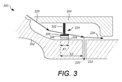
図3は、本発明の1つの実施形態に係るパージ流量の制御を行うことができるタービンセクション300の一部の拡大側断面図である。図3は、本発明の1つの実施形態に係るパージ流量を制御するよう動作可能な例示的なシール装置224を示す。図3は、シール装置224が入口孔222を通ってパージ流量を制御するよう動作可能であるタービンセクション300の一部を示す。例示的なシール装置224は、ステータ204上の複数の円周方向位置から片持ちにすることができる。パージ流量を制御するよう動作可能であるシール装置224は、ステータ204から片持ちにされた複数のスポーク302と、端部において、ロータ202に接して擦り合わせるブリストル304とを含むことができる。ブリストル304は、シールハブ308の内周上に装着することができ、別の円周方向位置にて複数のスポーク302により支持される。本発明の例示的な実施形態では、シール装置224は、約0.06インチの軸方向幅X1を有する軸方向成形リングとすることができる。更に、シール装置224は、あらゆる形状のものとすることができ、軸方向成形リングに限定されなくてもよい。例示的な実施形態において、ブリストル304は、ブリストルパック306内の1つの端部に装着することができ、該ブリストルパックは、シールハブ308に装着することができる。ブリストルパック306は、高密度にパックされた金属ワイヤのリング、すなわちブリストル304を固定することができる。ブリストル304は、ブリストルパック306内においてロータの回転方向のある角度で配列することができる。ブリストル長さは、約1インチ、すなわち2.5cmとすることができる。
FIG. 3 is an enlarged side cross-sectional view of a portion of a
通常、ガスタービンの始動及び運転停止時に、温度差、関連する熱膨張、及び負荷応力の組み合わせに起因して、ロータ部品は、ステータ部品に対する軸方向偏位を受ける可能性がある。ロータ及びステータ部品間の相対的軸方向偏位は、タービンの始動及び運転停止中に観測される。しかしながら、過渡的に変化する相対偏位は、全負荷時中に最大値に達し、タービンの定常状態運転又はその近傍の持続時間全体で一定に維持される。従って、始動前及び始動中、ステータ204により保持されるシール装置224は、1以上の入口孔222を閉鎖せず、加熱空気がボア部分に流れることができるように位置付けることができる。ステータがロータに対して軸方向に膨張すると、ステータ204により保持されるシール装置224は、ロータ202に対して相対的に移動し、1以上の入口孔222の少なくとも一部を覆い閉鎖し始めて、これによりボア領域への加熱空気の流入を制約することができる。始動持続時間後にタービンが定常状態運転又はその近傍に達すると、シール装置224は、ロータ202に対する移動を停止することができ、継続して入口孔222の全て又は一部を覆うことができる。運転停止中、ステータ及びロータ部品間の反対の軸方向偏位により、シール装置224が1つの入口孔22の少なくとも一部の覆いを取り除くことができる。1つの例示的な実施形態において、ロータ及びステータ部品間の軸方向の差分偏位は、始動後及び定常状態運転中に約0.1から約0.2インチの間とすることができる。この例示的な実施形態において、シール装置224の幅X1は、約0.04から約0.1インチとすることができ、シール装置224の第1の端部は、ガスタービンが始動する前に、入口孔222から約0.1から約0.2インチの距離X2に配置することができる。別の例示的な実施形態において、シール装置224とブリストル304の幅X1は、約0.06インチとすることができ、シール装置224の第1の端部は、入口孔222の第1の縁部から約0.18インチの距離X2に配置することができる。
Typically, during gas turbine start-up and shut-down, the rotor parts can experience axial deflection with respect to the stator parts due to a combination of temperature differences, associated thermal expansion, and load stress. Relative axial excursions between the rotor and stator parts are observed during turbine startup and shutdown. However, transiently changing relative excursions reach a maximum value at full load and remain constant throughout the steady state operation of the turbine or near it. Thus, before and during start-up, the
図4は、本発明の1つの実施形態に係る例示的なシール装置224の拡大正面図である。図4は、図2及び3に示すシール装置224の正面図400を示している。図4に示す例示的なシール装置224は、ブリストルパック306内に装着された1以上のブリストル304を含むことができ、ブリストルパックは、ロータ202を囲むシールハブ308の内周に装着することができる。シールハブ308の外周は、1以上のスポーク302に更に装着することができ、ここで1以上のスポーク302は、ステータ204の内周上に装着することができる。従って、シール装置224は、特定の円周地点でステータ204から垂下し、ロータと相対的に移動するよう動作可能であり、1以上の入口孔(図には示していない)の少なくとも一部を覆う。1つの入口孔の少なくとも一部は、1以上のブリストル304が入口孔を閉鎖し、従って、空気が入口孔に流入するのを阻止するときに、シール装置224により覆われる。更に、1以上のスポーク間の開口402は、ロータ202とステータ204間の軸方向空気流を可能にすることができる。従って、シール装置224が入口孔(図示せず)の少なくとも一部を覆うと、タービンセクション内の空気流は、ステータとロータとの間に軸方向に配向することができる。しかしながら、タービンの過渡運転中に、空気の一部は開口402を通って軸方向に流れ、残りは、入口孔を通りロータ202のボア内に流入する。従って、シール装置224の設計は、タービンセクション内の空気の比較的円滑な流れを促進し、空気の軸方向の流れを妨げず、よって損失を最小限にすることができる。
FIG. 4 is an enlarged front view of an
図5は、本発明の例示的な実施形態に係るロータ及び関連ステータの軸方向偏位、並びにこれらの相対的な軸方向偏位の例示的な変化を示す図である。図5は、ガスタービンの過渡状態及びその後の定常状態運転中のガスタービンのロータ及び関連するステータの例示的な軸方向偏位を表すプロット500を示す。プロット500では、横軸は、始動持続時間などの過渡運転の時間的継続(秒単位)、及びガスタービンのその後の全負荷運転の時間を表すことができる。更に、プロット500の縦軸は、タービンのステータ及びロータ部品間の軸方向偏位(インチ単位)を表すことができる。プロット500は、3つの曲線502、504及び506を示している。曲線502は、タービンが始動状態から定常状態又はその近傍に進んだときの時間に対するステータの軸方向偏位を表す。同様に、曲線504は、ガスタービンの過渡状態及び定常状態又はその近傍の間のロータの軸方向偏位を表す。しかしながら、曲線506は、ロータとステータとの間の相対軸方向偏位を表す。曲線506は、始動期間中にロータ及びステータ間の相対的軸方向偏位の漸次的増大を表し、次いでその後は、タービンの定常状態又はその近傍の開始点では軸方向偏位にあまり変化がないことを示している。本発明の1つの例示的な実施形態において、シール装置は、タービンの始動前にタービンセクション内に位置決めすることができ、入口孔は、始動時には最初は覆われておらず、次いで、タービンの始動から約5000秒の時間後に少なくとも部分的に覆うようにする。
FIG. 5 is a diagram illustrating exemplary deviations in the axial deviations of the rotor and associated stator and their relative axial deviations according to an illustrative embodiment of the invention. FIG. 5 shows a
図6は、本発明の例示的な実施形態に係るガスタービンのロータの半径方向温度勾配についての1つの例示的な方法600を示すフローチャートである。
FIG. 6 is a flowchart illustrating one
方法600は、ブロック602から始まることができる。ブロック602では、空気流通路がロータのボアに設けられ、該ロータボアは、1以上の入口孔と、スタックホイールにおける複数の孔とを含む。タービンのロータは、複数のスタックホイールから形成することができ、該スタックホイールは、環状ホイール間に交互に配置された中実ホイールを含む。空気流通路は、タービンの高温のガス通路からロータのボアへの通気道を設けることができる。空気流通路の一部を形成する1以上の入口孔は、ロータ内に定められるキャビティと連通することができる。キャビティは、中実ホイール内の複数の孔と更に連通することができる。従って、高温ガス通路からの空気は、環状ホイールの回りの蛇行流路を通り、中実ホイールを通ってロータのボアに配向することができる。蛇行流路は、空気流に対してタービンホイールの長さに沿って比較的大きな表面積の露出をもたらすことができる。このパージ流に対するロータ表面の露出が増えたことにより、ロータの比較的より効果的な加熱又は冷却をもたらし、従って、ガスタービンの過渡運転中のロータのリム及びボア間の半径方向の温度勾配をより有効に低減することができる。本発明の種々の実施形態では、中実ホイール内の複数の孔は、各ホイールの中心軸線から約0.2*Rと約0.65*Rとの間に配置することができ、ここでRは中実ホイール206のリム半径に等しい。ロータのボアに対する空気流通路の設計に続いて、工程はブロック604に進むことができる。
ブロック604において、1以上の孔を通るパージ空気の流れは、エンジンの運転中のロータ及び関連するステータの軸方向偏位に少なくとも部分的に基づいて制御することができる。タービンの始動及び運転停止中、ステータ部品に対するロータ部品の軸方向偏位をもたらすことができる。ロータ及びステータ部品間のこの相対的軸方向偏位は、タービンの始動中に時間と共に増大することができ、全負荷地点で最大に達する。全負荷地点を越えると、ロータ及びステータ部品間の偏位は、タービンの定常状態運転の全期間の間ほぼ一定に維持することができる。更に運転停止中、ロータ及びステータ部品間の相対的軸方向偏位は、同様に、時間と共に変化し減少することができる。従って、運転の過渡状態中、ステータの内周により保持されるシール装置は、ロータに対して相対的に移動し、入口孔の少なくとも一部を覆うことができる。更に、タービンが定常状態運転及びその近傍に達すると、シール装置は、ロータに対して移動せず、従って、引き続きタービンの定常状態運転中に入口孔の少なくとも一部を覆う。よって、シール装置は、ガスタービンの全運転状態にて入口孔への空気流を制御するよう動作することができる。本発明の1つの例示的な実施形態において、ステータ及びロータ部品間の軸方向偏位は、約0.01インチから約0.5インチである。更に、本発明の種々の実施形態において、シール装置は、シールハブの内周に装着された1以上のブリストルを含むことができる。このシールハブの外周は更に、1以上のスポークに装着することができ、ここで1以上のスポークは、ステータの内周に装着することができる。ロータ及びステータ間の相対移動は、最大軸方向偏位の地点で入口孔を少なくとも部分的に覆うロータ表面上のブリストルの動きを促進することができる。更に、スポ−クは、ステータ及びロータ間の軸方向空気流を許容することができるように円周方向に配列され、従って、流れの最小損失をもたらす。
In
方法600は、ブロック604に続いて終了することができる。
The
図6の方法600で説明された工程は、必ずしも図6に記載された順序で実行する必要はなく、本発明の実施形態に係る好適なあらゆる順序で実施することができる。加えて、本発明の特定の実施形態では、図6に記載の要素又は工程の全てよりも多いか又は少ない要素又は工程を実施することができる。
The steps described in
本発明の実施形態は、蒸気タービン、ガスタービン、及び同様のものなど、異なるタイプのタービンに適用することができる。更に、本発明の実施形態はまた、ガスタービンのタービンセクション又は圧縮機セクションなど、タービンの異なるセクション内で使用することができる。上述の明細書において取り上げられ/提供されたあらゆる実施例は、単に説明の目的で提供され、どのようにも本発明の範囲を限定するものではないことは明らかであろう。 Embodiments of the invention can be applied to different types of turbines, such as steam turbines, gas turbines, and the like. Furthermore, embodiments of the present invention can also be used in different sections of the turbine, such as a turbine section or compressor section of a gas turbine. It will be apparent that any examples taken / provided in the above specification are provided for illustrative purposes only and are not intended to limit the scope of the invention in any way.
本明細書は最良の形態を含む実施例を使用して本発明を開示し、また当業者が、あらゆる装置又はシステムを実施及び使用し、更にあらゆる組込み方法を実行することを含む、本発明の実施を行うことも可能にする。本発明の特許保護される範囲は、請求項によって定義され、当業者であれば想起される他の実施例を含むことができる。このような他の実施例は、請求項の文言と差違のない構造要素を有する場合、或いは、請求項の文言と僅かな差違を有する均等な構造要素を含む場合には、本発明の範囲内にあるものとする。 This specification discloses the invention using examples, including the best mode, and also includes those skilled in the art that make and use any device or system and perform any embedded method. It is also possible to carry out the implementation. The patentable scope of the invention is defined by the claims, and may include other examples that occur to those skilled in the art. Such other embodiments are within the scope of the invention if they have structural elements that do not differ from the words of the claims, or if they contain equivalent structural elements that have slight differences from the words of the claims. It shall be in
100 時間に対するリム−ボア温度勾配のプロット
200 タービンセクション
202 ロータ
204 ステータ
206 中実ホイール
208 環状ホイール
210 バケット
212 ノズル
214 リム
216 ボア
218 中心軸線
220 空気流通路
222 入口孔
224 シール装置
226 中実ホイールの複数の孔
230 圧縮機主要空気流通路
232 圧縮機及びタービンセクションに向かう残りの空気
234 タービンセクションを冷却/パージするために向かう残りの空気
300 タービンセクション部
302 金属スポーク
304 ブリストル
306 ブリストルパック
308 シールハブ
400 シール装置の正面図
402 開口
500 時間に対するロータ及びステータの軸方向偏位のプロット
502 時間に対するステータの軸方向偏位を示す曲線
504 時間に対するロータの軸方向偏位を示す曲線
506 時間に対するロータ及びステータ間の相対軸方向偏位を示す曲線
600 ロータの半径方向の温度勾配を制御するための方法
605 ブロック
610 ブロック
Plot of rim-bore temperature gradient against 100
Claims (21)
複数のスタックホイールを有するロータのボア(216)に空気を流すため、ロータ構造上に1以上の入口孔(222)と前記スタックホイールの少なくとも一部に複数の孔(226)とを備えた通路(220)を設ける段階(605)と、
前記ガスタービンの運転中に前記ロータ(202)と関連するステータ(204)との間の軸方向偏位に少なくとも部分的に基づいて、前記1以上の入口孔(222)への空気流を制御する段階(610)と
を含んでおり、前記空気流の少なくとも一部が前記スタックホイール内の複数の孔(226)を通って配向される方法。 A method for controlling a radial temperature gradient in a rotor (202) of a gas turbine comprising:
A passage having one or more inlet holes (222) on the rotor structure and a plurality of holes (226) in at least a portion of the stack wheel for flowing air through a rotor bore (216) having a plurality of stack wheels Providing (220) (605);
Controlling air flow to the one or more inlet holes (222) based at least in part on an axial deviation between the rotor (202) and an associated stator (204) during operation of the gas turbine. And wherein at least a portion of the air flow is directed through a plurality of holes (226) in the stack wheel.
前記ロータ(202)が複数のスタックホイールを有し、ロータ構造上に1以上の入口孔(222)と前記スタックホイール内の複数の孔(226)とを含む、前記ロータ(202)のボア(216)への空気流通路(220)と、
前記ガスタービンの運転中に前記ロータ(202)と関連するステータ(204)との間の軸方向偏位に少なくとも部分的に基づいて前記1以上の入口孔(222)への空気流を制御するためのシール装置(224)と
を備えており、前記空気流の少なくとも一部が、前記スタックホイール内の複数の孔(226)を通じて1以上のホイールをパージするように配向されるシステム。 A system (200) for controlling a radial temperature gradient in a gas turbine rotor (202) comprising:
The bore of the rotor (202), wherein the rotor (202) has a plurality of stack wheels and includes one or more inlet holes (222) and a plurality of holes (226) in the stack wheel on the rotor structure. 216) an air flow passageway (220);
Controlling air flow to the one or more inlet holes (222) based at least in part on an axial deviation between the rotor (202) and an associated stator (204) during operation of the gas turbine. And a sealing device (224) for directing at least a portion of the air flow to purge one or more wheels through a plurality of holes (226) in the stack wheel.
前記ロータ(202)が複数のスタックホイール(206、208)を有し、ロータ構造上に1以上の入口孔(222)と前記スタックホイール内の複数の孔(226)とを含む、前記ロータ(202)のボア(216)への空気流通路(220)と、
前記ガスタービンの運転中に前記ロータ(202)と関連するステータ(204)との間の軸方向偏位に少なくとも部分的に基づいて前記1以上の入口孔(222)への空気流を制御するためのシール装置(224)と
を備えており、前記空気流の少なくとも一部が、前記スタックホイール内の複数の孔(226)を通じて1以上のホイールをパージするように配向される装置(200)。 An apparatus (200) for controlling a radial temperature gradient in a gas turbine rotor (202) comprising:
The rotor (202) has a plurality of stack wheels (206, 208) and includes one or more inlet holes (222) and a plurality of holes (226) in the stack wheel on the rotor structure. 202) the air flow path (220) to the bore (216);
Controlling air flow to the one or more inlet holes (222) based at least in part on an axial deviation between the rotor (202) and an associated stator (204) during operation of the gas turbine. And an apparatus (200) for directing at least a portion of the air flow to purge one or more wheels through a plurality of holes (226) in the stack wheel. .
Applications Claiming Priority (2)
| Application Number | Priority Date | Filing Date | Title |
|---|---|---|---|
| US12/409,641 | 2009-03-24 | ||
| US12/409,641 US8186933B2 (en) | 2009-03-24 | 2009-03-24 | Systems, methods, and apparatus for passive purge flow control in a turbine |
Publications (3)
| Publication Number | Publication Date |
|---|---|
| JP2010223228A JP2010223228A (en) | 2010-10-07 |
| JP2010223228A5 JP2010223228A5 (en) | 2013-04-18 |
| JP5550400B2 true JP5550400B2 (en) | 2014-07-16 |
Family
ID=42229121
Family Applications (1)
| Application Number | Title | Priority Date | Filing Date |
|---|---|---|---|
| JP2010063517A Expired - Fee Related JP5550400B2 (en) | 2009-03-24 | 2010-03-19 | System, method and apparatus for passive purge flow control in a turbine |
Country Status (4)
| Country | Link |
|---|---|
| US (1) | US8186933B2 (en) |
| EP (1) | EP2236747B1 (en) |
| JP (1) | JP5550400B2 (en) |
| CN (1) | CN101852097B (en) |
Families Citing this family (17)
| Publication number | Priority date | Publication date | Assignee | Title |
|---|---|---|---|---|
| US20120134782A1 (en) * | 2010-11-30 | 2012-05-31 | Creston Lewis Dempsey | Purge systems for rotary machines and methods of assembling same |
| KR101271875B1 (en) | 2010-12-25 | 2013-06-05 | 주식회사 포스코 | Air Purge Device and Apparatus for Detecting Crack with it |
| US8807941B2 (en) * | 2011-02-03 | 2014-08-19 | General Electric Company | Cross-over purge flow system for a turbomachine wheel member |
| WO2014197044A2 (en) | 2013-03-12 | 2014-12-11 | United Technologies Corporation | Vane tip machining fixture assembly |
| US9528377B2 (en) | 2013-08-21 | 2016-12-27 | General Electric Company | Method and system for cooling rotor blade angelwings |
| US10480533B2 (en) * | 2013-09-10 | 2019-11-19 | United Technologies Corporation | Fluid injector for cooling a gas turbine engine component |
| US9664118B2 (en) | 2013-10-24 | 2017-05-30 | General Electric Company | Method and system for controlling compressor forward leakage |
| EP2868865A1 (en) * | 2013-10-31 | 2015-05-06 | Siemens Aktiengesellschaft | Gas turbine and method for cooling it |
| EP2868866A1 (en) | 2013-10-31 | 2015-05-06 | Siemens Aktiengesellschaft | Compressor for a gas turbine, comprising internal temperature compensation |
| US10036263B2 (en) | 2014-10-22 | 2018-07-31 | United Technologies Corporation | Stator assembly with pad interface for a gas turbine engine |
| US10612383B2 (en) * | 2016-01-27 | 2020-04-07 | General Electric Company | Compressor aft rotor rim cooling for high OPR (T3) engine |
| US10947993B2 (en) | 2017-11-27 | 2021-03-16 | General Electric Company | Thermal gradient attenuation structure to mitigate rotor bow in turbine engine |
| CN109113795A (en) * | 2018-10-23 | 2019-01-01 | 中国船舶重工集团公司第七0三研究所 | A kind of helium turbine rotor leaf dish |
| US11035251B2 (en) | 2019-09-26 | 2021-06-15 | General Electric Company | Stator temperature control system for a gas turbine engine |
| US11525400B2 (en) | 2020-07-08 | 2022-12-13 | General Electric Company | System for rotor assembly thermal gradient reduction |
| US11821326B2 (en) * | 2021-04-27 | 2023-11-21 | General Electric Company | Turbine containment system |
| US11879411B2 (en) | 2022-04-07 | 2024-01-23 | General Electric Company | System and method for mitigating bowed rotor in a gas turbine engine |
Family Cites Families (24)
| Publication number | Priority date | Publication date | Assignee | Title |
|---|---|---|---|---|
| US4023919A (en) * | 1974-12-19 | 1977-05-17 | General Electric Company | Thermal actuated valve for clearance control |
| US4445815A (en) * | 1980-06-09 | 1984-05-01 | United Technologies Corporation | Temperature regulation of air cycle refrigeration systems |
| US5316437A (en) * | 1993-02-19 | 1994-05-31 | General Electric Company | Gas turbine engine structural frame assembly having a thermally actuated valve for modulating a flow of hot gases through the frame hub |
| GB9401735D0 (en) * | 1994-01-29 | 1994-03-23 | Rolls Royce Plc | Component support structure |
| US5593274A (en) * | 1995-03-31 | 1997-01-14 | General Electric Co. | Closed or open circuit cooling of turbine rotor components |
| US5839267A (en) * | 1995-03-31 | 1998-11-24 | General Electric Co. | Cycle for steam cooled gas turbines |
| KR100389990B1 (en) * | 1995-04-06 | 2003-11-17 | 가부시끼가이샤 히다치 세이사꾸쇼 | Gas turbine |
| US5782076A (en) * | 1996-05-17 | 1998-07-21 | Westinghouse Electric Corporation | Closed loop air cooling system for combustion turbines |
| JP3901828B2 (en) * | 1998-02-17 | 2007-04-04 | 三菱重工業株式会社 | Steam cooled gas turbine |
| US6077035A (en) * | 1998-03-27 | 2000-06-20 | Pratt & Whitney Canada Corp. | Deflector for controlling entry of cooling air leakage into the gaspath of a gas turbine engine |
| KR20000071653A (en) * | 1999-04-15 | 2000-11-25 | 제이 엘. 차스킨, 버나드 스나이더, 아더엠. 킹 | Cooling supply system for stage 3 bucket of a gas turbine |
| DE19951570A1 (en) * | 1999-10-27 | 2001-05-03 | Abb Patent Gmbh | Device for compensating the axial thrust in turbomachinery |
| JP3361501B2 (en) * | 2000-03-02 | 2003-01-07 | 株式会社日立製作所 | Closed-circuit blade cooling turbine |
| DE10160996A1 (en) * | 2001-12-12 | 2003-06-18 | Rolls Royce Deutschland | Air mass flow control device |
| DE10303340A1 (en) * | 2003-01-29 | 2004-08-26 | Alstom Technology Ltd | cooling device |
| US6942445B2 (en) * | 2003-12-04 | 2005-09-13 | Honeywell International Inc. | Gas turbine cooled shroud assembly with hot gas ingestion suppression |
| GB0403198D0 (en) * | 2004-02-13 | 2004-03-17 | Rolls Royce Plc | Casing arrangement |
| DE102004014118A1 (en) | 2004-03-23 | 2005-10-13 | Alstom Technology Ltd | Arrangement for sealing a transition between cooling passages of two components of a turbomachine |
| US7090459B2 (en) * | 2004-03-31 | 2006-08-15 | General Electric Company | Hybrid seal and system and method incorporating the same |
| EP1907670B1 (en) * | 2005-07-27 | 2008-11-05 | Siemens Aktiengesellschaft | Cooled turbine blade for a gas turbine and use of such a turbine blade |
| US8057157B2 (en) * | 2007-10-22 | 2011-11-15 | General Electric Company | System for delivering air from a multi-stage compressor to a turbine portion of a gas turbine engine |
| US8016297B2 (en) * | 2008-03-27 | 2011-09-13 | United Technologies Corporation | Gas turbine engine seals and engines incorporating such seals |
| US8038399B1 (en) * | 2008-11-22 | 2011-10-18 | Florida Turbine Technologies, Inc. | Turbine rim cavity sealing |
| US7993102B2 (en) * | 2009-01-09 | 2011-08-09 | General Electric Company | Rotor cooling circuit |
-
2009
- 2009-03-24 US US12/409,641 patent/US8186933B2/en not_active Expired - Fee Related
-
2010
- 2010-03-15 EP EP10156534.9A patent/EP2236747B1/en not_active Not-in-force
- 2010-03-19 JP JP2010063517A patent/JP5550400B2/en not_active Expired - Fee Related
- 2010-03-23 CN CN201010155651XA patent/CN101852097B/en not_active Expired - Fee Related
Also Published As
| Publication number | Publication date |
|---|---|
| JP2010223228A (en) | 2010-10-07 |
| EP2236747A3 (en) | 2013-02-27 |
| US20100247282A1 (en) | 2010-09-30 |
| EP2236747B1 (en) | 2014-05-07 |
| CN101852097A (en) | 2010-10-06 |
| EP2236747A2 (en) | 2010-10-06 |
| CN101852097B (en) | 2013-08-21 |
| US8186933B2 (en) | 2012-05-29 |
Similar Documents
| Publication | Publication Date | Title |
|---|---|---|
| JP5550400B2 (en) | System, method and apparatus for passive purge flow control in a turbine | |
| CN101845996B (en) | Device and system for reducing second air flow in gas turbine | |
| RU2599413C2 (en) | Shell cooling passage | |
| JP4185476B2 (en) | Device for controlling clearance in a gas turbine | |
| JP4975990B2 (en) | Method and apparatus for maintaining the tip clearance of a rotor assembly | |
| JP5602485B2 (en) | gas turbine | |
| JP4138579B2 (en) | Gas turbine compressor and clearance control method for gas turbine compressor | |
| JP2013083250A (en) | Gas turbine | |
| JP6223111B2 (en) | gas turbine | |
| JP2011085136A (en) | Turbomachine rotor cooling | |
| JP6188580B2 (en) | Turbine casing provided with ring sector mounting means | |
| JP2015121224A (en) | Seal system for gas turbine | |
| JP6630295B2 (en) | Rotor assembly for turbomachinery | |
| JP6868005B2 (en) | Turbine for gas turbine engine with labyrinth seal element | |
| JP2007504395A (en) | Inflatable seal strip for steam turbine | |
| JP5677826B2 (en) | Method and apparatus for cooling first stage of double flow turbine | |
| US20150098791A1 (en) | Method and system for passive clearance control in a gas turbine engine | |
| JP2018066362A (en) | Steam turbine and temperature control method | |
| JP2011140943A (en) | Adverse pressure gradient seal mechanism | |
| JP2010159756A (en) | Split impeller configuration for synchronizing thermal response between turbine wheels | |
| US20110280721A1 (en) | Gas turbine | |
| US9816386B2 (en) | Casing arrangement for a gas turbine | |
| JP2008309051A (en) | Cooling structure for turbine shroud | |
| JP4909113B2 (en) | Steam turbine casing structure | |
| JP5478576B2 (en) | gas turbine |
Legal Events
| Date | Code | Title | Description |
|---|---|---|---|
| A521 | Written amendment |
Free format text: JAPANESE INTERMEDIATE CODE: A523 Effective date: 20130305 |
|
| A621 | Written request for application examination |
Free format text: JAPANESE INTERMEDIATE CODE: A621 Effective date: 20130305 |
|
| A131 | Notification of reasons for refusal |
Free format text: JAPANESE INTERMEDIATE CODE: A131 Effective date: 20140108 |
|
| A521 | Written amendment |
Free format text: JAPANESE INTERMEDIATE CODE: A523 Effective date: 20140403 |
|
| TRDD | Decision of grant or rejection written | ||
| A01 | Written decision to grant a patent or to grant a registration (utility model) |
Free format text: JAPANESE INTERMEDIATE CODE: A01 Effective date: 20140430 |
|
| A61 | First payment of annual fees (during grant procedure) |
Free format text: JAPANESE INTERMEDIATE CODE: A61 Effective date: 20140520 |
|
| R150 | Certificate of patent or registration of utility model |
Ref document number: 5550400 Country of ref document: JP Free format text: JAPANESE INTERMEDIATE CODE: R150 |
|
| LAPS | Cancellation because of no payment of annual fees |