CN101852097B - Systems, methods, and apparatus for passive purge flow control in a turbine - Google Patents
Systems, methods, and apparatus for passive purge flow control in a turbine Download PDFInfo
- Publication number
- CN101852097B CN101852097B CN201010155651XA CN201010155651A CN101852097B CN 101852097 B CN101852097 B CN 101852097B CN 201010155651X A CN201010155651X A CN 201010155651XA CN 201010155651 A CN201010155651 A CN 201010155651A CN 101852097 B CN101852097 B CN 101852097B
- Authority
- CN
- China
- Prior art keywords
- rotor
- impeller
- air
- stator
- flow
- Prior art date
- Legal status (The legal status is an assumption and is not a legal conclusion. Google has not performed a legal analysis and makes no representation as to the accuracy of the status listed.)
- Expired - Fee Related
Links
Images


Classifications
-
- F—MECHANICAL ENGINEERING; LIGHTING; HEATING; WEAPONS; BLASTING
- F01—MACHINES OR ENGINES IN GENERAL; ENGINE PLANTS IN GENERAL; STEAM ENGINES
- F01D—NON-POSITIVE DISPLACEMENT MACHINES OR ENGINES, e.g. STEAM TURBINES
- F01D5/00—Blades; Blade-carrying members; Heating, heat-insulating, cooling or antivibration means on the blades or the members
- F01D5/02—Blade-carrying members, e.g. rotors
- F01D5/08—Heating, heat-insulating or cooling means
- F01D5/085—Heating, heat-insulating or cooling means cooling fluid circulating inside the rotor
-
- F—MECHANICAL ENGINEERING; LIGHTING; HEATING; WEAPONS; BLASTING
- F01—MACHINES OR ENGINES IN GENERAL; ENGINE PLANTS IN GENERAL; STEAM ENGINES
- F01D—NON-POSITIVE DISPLACEMENT MACHINES OR ENGINES, e.g. STEAM TURBINES
- F01D11/00—Preventing or minimising internal leakage of working-fluid, e.g. between stages
- F01D11/001—Preventing or minimising internal leakage of working-fluid, e.g. between stages for sealing space between stator blade and rotor
-
- F—MECHANICAL ENGINEERING; LIGHTING; HEATING; WEAPONS; BLASTING
- F01—MACHINES OR ENGINES IN GENERAL; ENGINE PLANTS IN GENERAL; STEAM ENGINES
- F01D—NON-POSITIVE DISPLACEMENT MACHINES OR ENGINES, e.g. STEAM TURBINES
- F01D5/00—Blades; Blade-carrying members; Heating, heat-insulating, cooling or antivibration means on the blades or the members
- F01D5/02—Blade-carrying members, e.g. rotors
- F01D5/06—Rotors for more than one axial stage, e.g. of drum or multiple disc type; Details thereof, e.g. shafts, shaft connections
- F01D5/066—Connecting means for joining rotor-discs or rotor-elements together, e.g. by a central bolt, by clamps
-
- F—MECHANICAL ENGINEERING; LIGHTING; HEATING; WEAPONS; BLASTING
- F02—COMBUSTION ENGINES; HOT-GAS OR COMBUSTION-PRODUCT ENGINE PLANTS
- F02C—GAS-TURBINE PLANTS; AIR INTAKES FOR JET-PROPULSION PLANTS; CONTROLLING FUEL SUPPLY IN AIR-BREATHING JET-PROPULSION PLANTS
- F02C7/00—Features, components parts, details or accessories, not provided for in, or of interest apart form groups F02C1/00 - F02C6/00; Air intakes for jet-propulsion plants
- F02C7/12—Cooling of plants
- F02C7/16—Cooling of plants characterised by cooling medium
- F02C7/18—Cooling of plants characterised by cooling medium the medium being gaseous, e.g. air
Landscapes
- Engineering & Computer Science (AREA)
- Mechanical Engineering (AREA)
- General Engineering & Computer Science (AREA)
- Chemical & Material Sciences (AREA)
- Combustion & Propulsion (AREA)
- Turbine Rotor Nozzle Sealing (AREA)
- Control Of Turbines (AREA)
Abstract
Systems, methods and apparatus for passive purge flow control in a turbine are provided. Various embodiments of the invention include providing a path (220) for air to flow to a bore (216) of a rotor (202) with a plurality of stacked wheels. The air flow path (220) includes at least one inlet hole (222) on a rotor structure and a plurality of holes (226) in at least some of the stacked wheels. The method further involves control of air flow to the at least one inlet hole (222) based at least in part on axial deflection between the rotor (202) and an associated stator (204) during the gas turbine operation. Additionally, a portion of the air flowing into the inlet hole (206) is directed through the plurality of holes (226) in the at least some of the stacked wheels to purge the rotor (202).
Description
Technical field
[0001] embodiments of the invention relate generally to turbo machine, and more specifically, relate to system, the method and apparatus of passive purge (purge) current control for turbo machine.
Background technique
Turbo machine typically comprises rotary component (for example rotor) and fixed component (for example stator).The rotor of turbo machine can comprise a plurality of impellers that pile up.The outer radial zone of the impeller that piles up is called as rim section (rim portion), and the center radial zone of the impeller that piles up is called as bore portion.The operation of typical turbo machine relates to high temperature, and it can make the various members of turbo machine meet with extreme relatively thermal load.Therefore the rim section of the rotor of combustion gas turbine typically is exposed under the high temperature gas flow, and compares relative high temperature with the bore portion of rotor during starts being heated to, thereby produces greatly radially heat gradient between the wheel rim of rotor and hole.This wheel rim causes in the starting of combustion gas turbine and closes the stress cycle of cycle period to the heat gradient in hole, thereby and life-span of the mechanical component of turbo machine is had a negative impact.
In addition, typically in the turbine rotor structure, a plurality of solid and annular impellers are placed on the adjacent position, and by a plurality of axially extended bolts be located at joggle between the adjacent impeller and together fixed to one another.Thereby the different heating of impeller can cause great rotor hole stress and deflection, and it tends to open joggle.In addition, the heat condition of rotor and relevant impeller is different when starting, steady state operation and turbo machine are closed.During starts, the rim section of turbine wheel typically directly contacts with the turbine flow path of heat, and therefore rim section is tended to cause high relatively temperature gradient than the faster heating of bore portion.At the steady state run duration, conducted to bore portion from the heat of rim section, reduced temperature gradient, and almost balance the temperature difference between wheel rim and the hole.Yet, because wheel rim keeps directly contacting with hot gas, so even under steady state, the temperature of wheel rim is also tended to slightly higher than the temperature in hole.In the down periods, temperature gradient is tended to counter-rotating, because the flow path temperature of the reduction of the compressor section of turbo machine has been cooled off rim section, and bore portion is because thermal inertia still keeps heat.
Thereby need a kind ofly can guide the air of flow path or heating/cooling into the turbo machine hole in corresponding starting and down periods, and can be with its cut-out or the design that sharply reduces at the steady state run duration.Therefore need the mthods, systems and devices for the passive purge current control of turbo machine.
Summary of the invention
Embodiments of the invention can solve some or all the demand.Some embodiment of the present invention can be provided for system, the method and apparatus of the passive purge current control in the turbo machine.A kind of method of radial symmetry gradient of the rotor for the control combustion gas turbine is disclosed according to one embodiment of present invention.This method can comprise the path that the hole that makes the air flow rotor is provided, and rotor comprises a plurality of impellers that pile up.This inlet air flow path can comprise at least one the entrance hole on the rotor structure and be arranged in a plurality of holes that one of them piles up impeller a bit.This method also can be included in the combustion gas turbine run duration at least in part based on the axial deflection between rotor and the stator that is associated and control to the air-flow of described at least one entrance hole.In addition, a bootable part that flow into the air-flow in the entrance hole pass described one of them pile up a plurality of holes in the impeller a bit.
A kind of system of radial symmetry gradient of the rotor for the control combustion gas turbine is disclosed according to another embodiment of the present invention.This system can comprise the inlet air flow path in the hole that offers rotor, and rotor comprises a plurality of impellers that pile up.This inlet air flow path can comprise at least one the entrance hole on the rotor structure and the impeller that piles up in a plurality of holes.This system also can comprise seal arrangement, its can operate with at the combustion gas turbine run duration at least in part based on the axial deflection between rotor and the stator that is associated and control to the air-flow of this at least one entrance hole.In addition, bootable at least a portion flows into the air-flow in this at least one entrance hole, in order to purge at least one impeller by a plurality of holes in the impeller that piles up.
A kind of device of radial symmetry gradient of the rotor for the control combustion gas turbine is disclosed according to still another embodiment of the invention.This device can comprise the inlet air flow path in the hole that offers rotor, and rotor comprises a plurality of impellers that pile up.Can comprise a plurality of holes in the impeller that piles up of at least one entrance hole on the rotor structure and rotor to this inlet air flow path in the hole of rotor.This device also can comprise seal arrangement, and it is used for controlling to based on the axial deflection between rotor and the stator that is associated at least in part at the combustion gas turbine run duration air-flow of this at least one entrance hole.In addition, bootable at least a portion air-flow is so that a plurality of holes of passing in the impeller that piles up purge at least one impeller.
Those of skill in the art from following embodiment, accompanying drawing and claims with distinct other embodiments of the invention, aspect and feature.
Description of drawings
Briefly described the present invention, described the present invention referring now to accompanying drawing, these drawings are not necessarily drawn in proportion, wherein:
Fig. 1 has shown according to the chart of the wheel rim that is associated with rotor combustion gas turbine a illustrative embodiment of the present invention to an example of the temperature gradient variation in hole.
Fig. 2 is the partial cross-sectional side view according to an example of the compressor section of the available combustion gas turbine of various embodiments of the invention.
Fig. 3 is the cross-sectional side view of the amplification of the part of turbine section according to an embodiment of the invention, has wherein realized the control of purge stream.
Fig. 4 is a kind of according to an embodiment of the invention schematic front view of example seal device.
Fig. 5 is the chart that has shown according to an exemplary variations of the axial deflection of the rotor of an illustrative embodiment of the present invention and associated stator and their deflection to axial.
Fig. 6 is flow chart, and it has shown the exemplary method of radial symmetry gradient according to a kind of rotor for the control combustion gas turbine of an illustrative embodiment of the present invention.
List of parts
100 wheel rims are to the plotted curve of hole temperature gradient to the time; 200 turbine section; 202 rotors; 204 stators; 206 solid impellers; 208 annular impellers; 210 blades; 212 nozzles; 214 wheel rims; 216 holes; 218 cener lines; 220 air path; 222 entrance holes; 224 seal arrangements; A plurality of holes in the 226 solid impellers; The 230 compressor primary airs path of flowing; 232 flow to the surplus air of burner and turbine section; 234 flow to the surplus air of cooling/purging turbine section; 300 turbine section parts; 302 metal spokes; 304 bristles; 306 setal fascicles (bristle pack); 308 sealing wheel hubs; The front view of 400 seal arrangements; 402 openings; The axial deflection of 500 rotors and stator is to the plotted curve of time; 502 show the time dependent curve of axial deflection of stator; 504 show the time dependent curve of axial deflection of rotor; 506 show the time dependent curve of deflection to axial between rotor and the stator; 600 are used for the method for the radial symmetry gradient of control rotor; 605 block diagrams 1; 610 block diagrams 2.
Embodiment
Now will more completely describe illustrative embodiment of the present invention with reference to accompanying drawing below, show some but non-whole embodiment of the present invention in the accompanying drawings.The present invention can many different forms embody, and should not be regarded as being limited to the embodiment of this paper statement; On the contrary, these embodiments are provided so that the present invention openly will satisfy suitable legal requirements.Run through the similar label of full text and represent similar element.
Disclosed is for system, the method and apparatus of the passive purge current control of turbo machine, comprises the radial symmetry gradient in the rotor of controlling combustion gas turbine.Various embodiment of the present invention can comprise a kind of seal arrangement, and it is used for controlling to the air-flow of epitrochanterian at least one entrance hole, and it can move with purging air, thereby reduces the radial symmetry gradient in the rotor.Purging air can be in the hole of during starts heating turbine wheel of combustion gas turbine, and subsequently in the hole of turbo machine down periods cooling turbine impeller.At the combustion gas turbine run duration, can be at least in part based on the axial deflection between rotor and the stator that is associated and the flow control that realizes passing seal arrangement.In order in some embodiment of embodiment, to realize aforementioned purpose, also can compressor air-discharging be offered rotor hole by inlet air flow path, and enter cavity between the turbine wheel of rotor, wherein inlet air flow path can comprise a plurality of holes of the turbine wheel that is arranged in epitrochanterian entrance hole and rotor.
At least one technique effect of some embodiment of the present invention as herein described is that the hole that can be turbine rotor provides inlet air flow path, with the radial symmetry gradient in the control rotor.This layout can be by eliminating or otherwise be minimized in the steady state run duration and being used for loss that the use of purging air of cooling rotor hole is associated and improving the performance of turbo machine.In addition, the seal arrangement that is used for the control sweep air flow can utilize the motion to axial between rotor and the stator component, and wherein this motion occurs in the turbo machine run duration.In addition, the design of seal arrangement can guarantee that air-flow can not be interfered owing to the existence of seal arrangement or be unaffected relatively, thereby the flow loss of having guaranteed to pass the minimum of turbine section flows stably with relative.Therefore, use seal arrangement to control the technique effect that purge stream can have the performance of improving turbo machine.
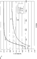
Fig. 1 has shown according to the chart of the wheel rim that is associated with rotor combustion gas turbine a illustrative embodiment of the present invention to an example of hole temperature gradient variation.Fig. 1 has shown curve Figure 100, and it represents the variation example that arrives the hole temperature gradient at the wheel rim of the transition of combustion gas turbine and follow-up steady state run duration turbine wheel.In curve Figure 100, horizontal axis can represent the endurance (second) of the operation of combustion gas turbine.The time that can comprise the transition operation duration of operation of combustion gas turbine, for example duration of starting, and the time of the oepration at full load of follow-up combustion gas turbine.In addition, vertical axis can represent radial flange in the turbine wheel of rotor to hole temperature gradient (be unit with the Fahrenheit).Curve Figure 100 has shown in the progressively rising of transition run duration (for example during starting period of combustion gas turbine) wheel rim to the hole temperature gradient.Next, peaking was located in the centre of curve during duration of starting at about 1500 seconds, then along with combustion gas turbine arrival steady state or near steady state operation and decline gradually.In various embodiments of the present invention, the character of the curve in the duration of starting also can represent the system performance of the down periods of gas turbine engines.Curve Figure 100 shown in Fig. 1 keeps relatively flat in the steady state of combustion gas turbine or near the steady state run duration, and in fact expression does not have or seldom have to exceed wheel rim that full load puts to the hole variation of temperature when combustion gas turbine reaches steady state or move near steady state.
Typically, in the some of them of combustion gas turbine or all during the operation period, the purge stream of guiding the hole of rotor into by utilization is controlled high wheel rim to turbine wheel to the hole temperature gradient.Yet, by during the different operation phase of turbo machine, controlling purge stream rightly, can improve the efficient of turbo machine.Because as shown in fig. 1, wheel rim stays in acceptable value to the hole temperature gradient after the full load time point, so in the steady state of combustion gas turbine or near the steady state run duration to purging air seldom or do not have a demand.In steady state or be blown into air in the hole of rotor near the steady state run duration and remain in the turbine section and circulate, thereby influence the efficient of turbo machine.Yet, may need purge stream in the down periods of turbo machine, because between wheel rim and bore region, compare relative fast cooling with bore portion and understand the formation temperature gradient owing to rim section.Layout as shown in Figure 2 can work in order to control the purge stream in the hole of guiding rotor into during the different operation phase of turbo machine, thereby and can guarantee relatively effectively using of purging air.
Fig. 2 is the cross-sectional side view of the amplification of an example compressor section 200 of available combustion gas turbine according to various embodiments of the present invention.Fig. 2 has shown an example context of an example compressor section 200 of combustion gas turbine.Additionally or alternatively, other embodiments of the invention can comprise that the turbine section of combustion gas turbine is as example context.
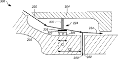
Therefore can provide inlet air flow path 220, hole 216 is led in its hot gas flow path from compressor section 200, passes the tail end of rotor 202.Inlet air flow path 220 can comprise at least one the entrance hole 222 on the rotor structure, can control the air-flow that passes this entrance hole by seal arrangement 224.Inlet air flow path 220 also can be connected to entrance hole 222 on a plurality of holes 226 in one of them a little turbine wheel.Thereby the air of self-heating gas path is introduced in the hole 216 in the future, by also pass through a plurality of holes 226 in the solid impeller 206 around the path of annular impeller 208.According to an exemplary embodiment, can be derived from the primary air-flow path 230 of compressor along the purging air part of inlet air flow path 220.The remainder of primary air can flow to burner and turbine section 232, perhaps is used for cooling/purging turbine section 234.
In addition, in certain embodiments of the present invention, allowing that air-flow passes a plurality of holes 226 of solid impeller 206 can be along the cener line 218 of motor or angled with it.In addition, at least one embodiment, a plurality of holes 226 in the solid impeller 206 can be positioned between the extremely about 0.65*R of central axis 218 about 0.2*R of each impeller, and wherein R is the flange radius of solid impeller 206.
In various embodiments of the present invention, formed air path 220 a part at least one entrance hole 222 can be limited to rotor 202 in cavity become stream to be communicated with, and cavity can with solid turbine wheel 206 in a plurality of holes flow connection for 226 one-tenths.Inlet air flow path 220 thereby guiding stream arrive hole 216 from the hot gas path by entrance hole 222.Next, inlet air flow path 220 is passed the hole 226 in the solid impeller 206, and around the annular impeller 208 that alternately is positioned between the solid impeller, thereby formation is called as the flow path of the bending of snakelike flow path.Being formed at snakelike flow path in the bore region of rotor 202 can make relatively large surface area exposure along the length of turbine wheel under air-flow.The surface for air-flow that increases exposes and causes relatively more effectively heating or cooling compressor impeller bore surface.Thereby the transition run duration that serpentine path is used in combustion gas turbine more effectively reduces the radial symmetry gradient between the hole 216 of wheel rim 214 and rotor 202.
Fig. 3 is the cross-sectional side view of amplification of the part of turbine section 300 according to an embodiment of the invention, can realize the control of purge stream in this turbine section.Fig. 3 has shown example seal device 224 according to an embodiment of the invention, and it can operate to control purge stream.Fig. 3 has shown the part of turbine section 300, and wherein seal arrangement 224 can operate to control the purge stream of passing entrance hole 222.This example seal device 224 can overhang from a plurality of circumferential positions on the stator 204.The seal arrangement 224 that can operate to control purge stream can comprise a plurality of spokes 302 that overhang from stator 204, locates to have the bristle 304 against rotor 202 frictions endways.Bristle 304 can be installed on the inner circumference of sealing wheel hub 308, and sealing wheel hub 308 is supported by a plurality of spokes 302 at different circumferential position places.In one exemplary embodiment of the present invention, seal arrangement 224 can be the ring of axial shape, has about 0.06 inch axial width X1.In addition, seal arrangement 224 can have Any shape, and can be not limited to axial shape ring.In one exemplary embodiment, bristle 304 can be installed in the setal fascicle 306 at one end, and setal fascicle 306 can be installed on the sealing wheel hub 308.It is bristle 304 that setal fascicle 306 can be fixed the wire closely tied up of circle.In setal fascicle 306, bristle 304 can angled sense of rotation setting along rotor.It is 2.5cm that bristle length can be about 1 inch.
Typically, in starting and the down periods of combustion gas turbine, rotor part is possible owing to axial deflection is experienced in the temperature difference, relevant thermal expansion and the combination of load stress with respect to stator component.Observe deflection to axial between rotor part and stator component in the starting of turbo machine and down periods.Yet the relative deflection of instantaneous variation reaches maximum value during full load, and keeps constant in the steady state of turbo machine or near the whole endurance of steady state operation.Thereby before starting and during starts, the seal arrangement 224 that keeps from stator 204 can be positioned to make it not block this at least one entrance hole 222, and the air of heating can flow to bore portion.When stator expands with respect to rotor axial ground, can be relatively mobile with respect to rotor 202 from the seal arrangement 224 that stator 204 keeps, and at least a portion that begins to cover and block this at least one entrance hole 222, thereby be restricted to the flow that adds hot air of bore region.When turbo machine reached steady state or moves near steady state after duration of starting, seal arrangement 224 can stop mobile with respect to rotor 202, and can continue to cover entrance hole 222 all or part of.In the down periods, the tolerable of the deflection to axial seal arrangement 224 of the counter-rotating between stator component and the rotor part exposes at least a portion of this entrance hole 222.In one exemplary embodiment, after starting and at the steady state run duration, can be between about 0.1 inch to about 0.2 inch in the different axial deflection between rotor part and the stator component.For this exemplary embodiment, the width X1 of seal arrangement 224 and bristle 304 can be between about 0.04 inch to about 0.1 inch, and before combustion gas turbine starting, first end of seal arrangement 224 can be placed on from entrance hole 222 about 0.1 inch to about 0.2 inch distance X 2 places.According to another exemplary embodiment, the width X1 of seal arrangement 224 and bristle 304 can be about 0.06 inch, and first end of seal arrangement 224 can be placed on distance X 2 places about 0.18 inch from first edge of entrance hole 222.
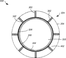
Fig. 4 is the front view of the amplification of example seal device 224 according to an embodiment of the invention.Fig. 4 has shown the front view 400 of the seal arrangement 224 shown in Fig. 2 and Fig. 3.Shown example seal device 224 comprises the one or more bristles 304 that are installed in the setal fascicle 306 among Fig. 4, and setal fascicle can be installed on the inner circumference of the sealing wheel hub 308 that surrounds rotor 202.The excircle of sealing wheel hub 308 also can be installed on one or more spokes 302, and wherein these one or more spokes 302 can be installed on the inner circumference of stator 204.Thereby seal arrangement 224 dangles at some circumferential point from stator 204, and can operate to move with respect to rotor, and covers at least a portion of at least one entrance hole (not shown).When one or more bristles 304 blocked the entrance hole, at least a portion of this entrance hole can cover by sealed device 224, thereby and prevented that air from flowing in the entrance hole.Opening 402 between these external one or more spokes can allow the axial flow between rotor 202 and stator 204.Thereby when seal arrangement 224 covers at least a portion of this entrance hole (not shown), can be with the axially guiding between stator and rotor of the air-flow in the turbine section.Yet at the transition run duration of turbo machine, the part air axially flows through opening 402, and remaining air flows through the entrance hole, and flows in the hole of rotor 202.Thereby the design of seal arrangement 224 can promote in the turbine section that air flows relatively stably, and can not stop up the axial flow of air, thus minimum losses.
Fig. 5 is the chart that has shown according to the variation example of the axial deflection of the rotor of an illustrative embodiment of the present invention and associated stator and their deflection to axial.Fig. 5 has shown plotted curve 500, and its rotor that represents combustion gas turbine and relevant stator are in the transition of combustion gas turbine and the exemplary axial deflection of follow-up steady state run duration.In plotted curve 500, horizontal axis can represent the endurance (second) (for example duration of starting) of transition operation, and the follow-up oepration at full load time of combustion gas turbine.In addition, the vertical axis in the plotted curve 500 can represent at the stator component of turbo machine and the axial deflection between the rotor part (be unit with the inch).Plotted curve 500 has shown three curves 502,504 and 506.Curve 502 representative moves to steady state or stator axial deflection in time during near steady state from starting state when turbo machine.Similarly, curve 504 representative is in the transient state of combustion gas turbine and steady state or near the axial deflection of the rotor of steady state run duration.And the curve 506 to axial deflections of representative between rotor and stator.Curve 506 represents the gradually increase of deflection to axial during duration of starting between rotor and the stator, then shown then along with turbo machine begin to enter steady state or when moving near steady state the axial deflection aspect do not change relatively.In one exemplary embodiment of the present invention, seal arrangement can be positioned in the turbine section before turbine start, make that the entrance hole can be not capped at first when starting, can be covered at least in part after about 5000 seconds time at turbine start then.
Fig. 6 is the flow chart that has shown according to the exemplary method 600 of the radial symmetry gradient of the rotor that is used for the control combustion gas turbine of an illustrative embodiment of the present invention.
At block diagram 604 places, can be at least in part control the flow of the purging air that passes this at least one hole based on the axial deflection of rotor and the stator that is associated at the motor run duration.In starting and the down periods of turbo machine, may cause rotor part with respect to the axial deflection of stator component.Between rotor part and stator component this deflection to axial can be along with the time increases during turbine start, and reaches maximum value at point at full capacity.Surpass point at full capacity, the deflection between rotor part and the stator component can keep almost constant in the whole endurance of turbo machine steady state operation.These external down periods, the deflection to axial between rotor part and stator component can change again, and descends along with the time.Thereby, during the transition running state, can be relatively mobile with respect to rotor from the seal arrangement that the inner circumference of stator keeps, and cover at least a portion of entrance hole.In addition, when turbo machine reached steady state or moves near steady state, seal arrangement was mobile with respect to rotor, and thereby continued to cover at least a portion of entrance hole at the steady state run duration of turbo machine.Thereby seal arrangement can operate to control to the air-flow of entrance hole under all running statees of combustion gas turbine.In one exemplary embodiment of the present invention, the axial deflection between stator component and rotor part is about 0.01 inch to about 0.5 inch.Among these external various embodiments of the present invention, seal arrangement can comprise the one or more bristles on the inner circumference that is installed in the sealing wheel hub.The excircle of this sealing wheel hub can further be installed on one or more spokes, and wherein these one or more spokes can be installed on the inner circumference of stator.Relative movement between rotor and stator can promote the motion of bristle on rotor surface, thereby covers the entrance hole at least in part at maximum axial inflexion point place.In addition, also spoke circumferentially is arranged so that between stator and rotor, can allow axial air to flow, thereby causes minimum flow loss.
This method 600 can finish after block diagram 604.
Operation described in the method 600 of Fig. 6 not necessarily must be carried out according to the order of stating among Fig. 6, but can carry out according to any suitable order according to embodiments of the invention.In addition in certain embodiments of the present invention, can carry out than whole key elements of stating among Fig. 6 or all operate more or less key element or operation.
Embodiments of the invention are applicable to dissimilar turbo machines, for example steam turbine, combustion gas turbine etc.And embodiments of the invention also can for example use in the turbine section of combustion gas turbine or the compressor section at the different sections of turbo machine.Should be understood that in the specification of front institute's any example of adopting or providing all only provides for explanatory purposes, in any case and scope of the present invention without limits all.
This printed instructions usage example comes open the present invention, comprises optimal mode, and makes those of skill in the art can put into practice the present invention, comprises manufacturing and utilizes any device or system, and carry out the method for any institute combination.Define the patentable scope of the present invention in the claims, and can comprise other example that those of skill in the art expect.If it not is the structural element that is different from the literal language of claim that these other examples have, if perhaps it comprises the equivalent structure element that does not have essence difference with the literal language of claim, these other examples all belong in the scope of claim so.
Claims (20)
1. the method for the radial symmetry gradient in the rotor of controlling combustion gas turbine, described method comprises:
Provide the path in the hole that flows to described rotor to air, described rotor comprises a plurality of impellers that pile up, and wherein said path comprises at least one entrance hole on the rotor structure and a plurality of holes in one of them a little described impeller that pile up, and
Run duration at described combustion gas turbine, based on the axial deflection between described rotor and the stator that is associated and control to the air-flow of described at least one entrance hole, at least a portion of wherein said air-flow is guided through a plurality of holes in the described impeller that piles up at least in part.
2. method according to claim 1 is characterized in that, the described impeller that piles up comprises solid impeller and annular impeller, and wherein, described air-flow is guided through around the path of described annular impeller and passes described solid impeller.
3. method according to claim 2 is characterized in that, the described a plurality of holes in the described impeller that piles up are located between the 0.65*R at the central axis 0.2*R apart from each impeller, and R equals the flange radius of described solid impeller herein.
4. method according to claim 1 is characterized in that, described axial deflection is 0.01 inch to 0.5 inch.
5. method according to claim 1 is characterized in that, to the sealed device control of the air-flow of described at least one entrance hole.
6. method according to claim 5 is characterized in that, the described seal arrangement that keeps from stator can relatively move with respect to rotor, and covers at least a portion of described at least one entrance hole.
7. method according to claim 5, it is characterized in that, described seal arrangement comprises the one or more bristles on the inner circumference that is installed in the sealing wheel hub, the excircle of wherein said sealing wheel hub is installed on one or more spokes, wherein said one or more spoke is installed on the inner circumference of described stator, and the opening between the wherein said spoke allows the axial air between described stator and the described rotor to flow.
8. the system of the radial symmetry gradient of a rotor that is used for the control combustion gas turbine, described system comprises:
To the inlet air flow path in the hole of described rotor, described rotor comprises a plurality of impellers that pile up, and wherein said path comprises at least one entrance hole on the rotor structure and a plurality of holes in the described impeller that piles up; And
Seal arrangement, it is used for controlling to based on the axial deflection between described rotor and the stator that is associated at least in part at the run duration of described combustion gas turbine the air-flow of described at least one entrance hole, at least a portion of wherein said air-flow is guided through a plurality of holes in the described impeller that piles up, thereby purges at least one impeller.
9. system according to claim 8 is characterized in that, the described impeller that piles up comprises solid impeller and annular impeller, and wherein said air-flow is guided through the path that centers on described annular impeller and passes described solid impeller.
10. system according to claim 9 is characterized in that, the described a plurality of holes in the described impeller that piles up are located between the 0.65*R at the central axis 0.2*R apart from each impeller, and R equals the flange radius of described solid impeller herein.
11. system according to claim 8 is characterized in that, described at least one the entrance hole on the described rotor structure is communicated with the cavity in being limited to described rotor, and wherein said cavity is communicated with a plurality of holes in the described impeller that piles up.
12. system according to claim 8 is characterized in that, described axial deflection is 0.01 inch to 0.5 inch.
13. system according to claim 8 is characterized in that, the described seal arrangement that keeps from stator can relatively move with respect to rotor, and covers at least a portion of described at least one entrance hole.
14. system according to claim 8, it is characterized in that, described seal arrangement comprises the one or more bristles on the inner circumference that is installed in the sealing wheel hub, the excircle of wherein said sealing wheel hub is installed on one or more spokes, wherein said one or more spoke is installed on the inner circumference of described stator, and the opening between the wherein said spoke allows the axial air between described stator and the described rotor to flow.
15. the device for the radial symmetry gradient of the rotor of control combustion gas turbine, described device comprises:
To the inlet air flow path in the hole of described rotor, described rotor comprises a plurality of impellers that pile up, and wherein said path comprises at least one entrance hole on the rotor structure and a plurality of holes in the described impeller that piles up; And
Seal arrangement, it is used for controlling to based on the axial deflection between described rotor and the stator that is associated at least in part at the run duration of described combustion gas turbine the air-flow of described at least one entrance hole, at least a portion of wherein said air-flow is guided through a plurality of holes in the described impeller that piles up, thereby purges at least one impeller.
16. device according to claim 15 is characterized in that, described at least one the entrance hole on the described rotor structure is communicated with the cavity in being limited to described rotor, and wherein said cavity is communicated with a plurality of holes in the described impeller that piles up.
17. device according to claim 15 is characterized in that, described axial deflection is 0.01 inch to 0.5 inch.
18. device according to claim 15 is characterized in that, described seal arrangement is the ring of axial shape, and its axial width is 0.06 inch.
19. device according to claim 15 is characterized in that, the described seal arrangement that keeps from stator can relatively move with respect to rotor, and covers at least a portion of described at least one entrance hole.
20. device according to claim 15, it is characterized in that, described seal arrangement comprises the one or more bristles on the inner circumference that is installed in the sealing wheel hub, the excircle of wherein said sealing wheel hub is installed on one or more spokes, wherein said one or more spoke is installed on the inner circumference of described stator, and the opening between the wherein said spoke allows the axial air between described stator and the described rotor to flow.
Applications Claiming Priority (2)
| Application Number | Priority Date | Filing Date | Title |
|---|---|---|---|
| US12/409641 | 2009-03-24 | ||
| US12/409,641 US8186933B2 (en) | 2009-03-24 | 2009-03-24 | Systems, methods, and apparatus for passive purge flow control in a turbine |
Publications (2)
| Publication Number | Publication Date |
|---|---|
| CN101852097A CN101852097A (en) | 2010-10-06 |
| CN101852097B true CN101852097B (en) | 2013-08-21 |
Family
ID=42229121
Family Applications (1)
| Application Number | Title | Priority Date | Filing Date |
|---|---|---|---|
| CN201010155651XA Expired - Fee Related CN101852097B (en) | 2009-03-24 | 2010-03-23 | Systems, methods, and apparatus for passive purge flow control in a turbine |
Country Status (4)
| Country | Link |
|---|---|
| US (1) | US8186933B2 (en) |
| EP (1) | EP2236747B1 (en) |
| JP (1) | JP5550400B2 (en) |
| CN (1) | CN101852097B (en) |
Families Citing this family (17)
| Publication number | Priority date | Publication date | Assignee | Title |
|---|---|---|---|---|
| US20120134782A1 (en) * | 2010-11-30 | 2012-05-31 | Creston Lewis Dempsey | Purge systems for rotary machines and methods of assembling same |
| KR101271875B1 (en) | 2010-12-25 | 2013-06-05 | 주식회사 포스코 | Air Purge Device and Apparatus for Detecting Crack with it |
| US8807941B2 (en) * | 2011-02-03 | 2014-08-19 | General Electric Company | Cross-over purge flow system for a turbomachine wheel member |
| US10018061B2 (en) | 2013-03-12 | 2018-07-10 | United Technologies Corporation | Vane tip machining fixture assembly |
| US9528377B2 (en) | 2013-08-21 | 2016-12-27 | General Electric Company | Method and system for cooling rotor blade angelwings |
| WO2015038451A1 (en) * | 2013-09-10 | 2015-03-19 | United Technologies Corporation | Fluid injector for cooling a gas turbine engine component |
| US9664118B2 (en) | 2013-10-24 | 2017-05-30 | General Electric Company | Method and system for controlling compressor forward leakage |
| EP2868865A1 (en) * | 2013-10-31 | 2015-05-06 | Siemens Aktiengesellschaft | Gas turbine and method for cooling it |
| EP2868866A1 (en) | 2013-10-31 | 2015-05-06 | Siemens Aktiengesellschaft | Compressor for a gas turbine, comprising internal temperature compensation |
| US10036263B2 (en) | 2014-10-22 | 2018-07-31 | United Technologies Corporation | Stator assembly with pad interface for a gas turbine engine |
| US10612383B2 (en) * | 2016-01-27 | 2020-04-07 | General Electric Company | Compressor aft rotor rim cooling for high OPR (T3) engine |
| US10947993B2 (en) | 2017-11-27 | 2021-03-16 | General Electric Company | Thermal gradient attenuation structure to mitigate rotor bow in turbine engine |
| CN109113795A (en) * | 2018-10-23 | 2019-01-01 | 中国船舶重工集团公司第七0三研究所 | A kind of helium turbine rotor leaf dish |
| US11035251B2 (en) | 2019-09-26 | 2021-06-15 | General Electric Company | Stator temperature control system for a gas turbine engine |
| US11525400B2 (en) | 2020-07-08 | 2022-12-13 | General Electric Company | System for rotor assembly thermal gradient reduction |
| US11821326B2 (en) * | 2021-04-27 | 2023-11-21 | General Electric Company | Turbine containment system |
| US11879411B2 (en) | 2022-04-07 | 2024-01-23 | General Electric Company | System and method for mitigating bowed rotor in a gas turbine engine |
Citations (4)
| Publication number | Priority date | Publication date | Assignee | Title |
|---|---|---|---|---|
| US5316437A (en) * | 1993-02-19 | 1994-05-31 | General Electric Company | Gas turbine engine structural frame assembly having a thermally actuated valve for modulating a flow of hot gases through the frame hub |
| US6746208B2 (en) * | 2000-03-02 | 2004-06-08 | Hitachi, Ltd. | Closed circuit blade-cooled turbine |
| US6779967B2 (en) * | 2001-12-12 | 2004-08-24 | Rolls-Royce Deutschland Ltd & Co Kg | Device for air mass flow control |
| US20090035128A1 (en) * | 2005-07-27 | 2009-02-05 | Fathi Ahmad | Cooled turbine blade for a gas turbine and use of such a turbine blade |
Family Cites Families (20)
| Publication number | Priority date | Publication date | Assignee | Title |
|---|---|---|---|---|
| US4023919A (en) * | 1974-12-19 | 1977-05-17 | General Electric Company | Thermal actuated valve for clearance control |
| US4445815A (en) * | 1980-06-09 | 1984-05-01 | United Technologies Corporation | Temperature regulation of air cycle refrigeration systems |
| GB9401735D0 (en) * | 1994-01-29 | 1994-03-23 | Rolls Royce Plc | Component support structure |
| US5839267A (en) * | 1995-03-31 | 1998-11-24 | General Electric Co. | Cycle for steam cooled gas turbines |
| US5593274A (en) * | 1995-03-31 | 1997-01-14 | General Electric Co. | Closed or open circuit cooling of turbine rotor components |
| KR100389990B1 (en) * | 1995-04-06 | 2003-11-17 | 가부시끼가이샤 히다치 세이사꾸쇼 | Gas turbine |
| US5782076A (en) * | 1996-05-17 | 1998-07-21 | Westinghouse Electric Corporation | Closed loop air cooling system for combustion turbines |
| JP3901828B2 (en) * | 1998-02-17 | 2007-04-04 | 三菱重工業株式会社 | Steam cooled gas turbine |
| US6077035A (en) * | 1998-03-27 | 2000-06-20 | Pratt & Whitney Canada Corp. | Deflector for controlling entry of cooling air leakage into the gaspath of a gas turbine engine |
| KR20000071653A (en) * | 1999-04-15 | 2000-11-25 | 제이 엘. 차스킨, 버나드 스나이더, 아더엠. 킹 | Cooling supply system for stage 3 bucket of a gas turbine |
| DE19951570A1 (en) * | 1999-10-27 | 2001-05-03 | Abb Patent Gmbh | Device for compensating the axial thrust in turbomachinery |
| DE10303340A1 (en) * | 2003-01-29 | 2004-08-26 | Alstom Technology Ltd | cooling device |
| US6942445B2 (en) * | 2003-12-04 | 2005-09-13 | Honeywell International Inc. | Gas turbine cooled shroud assembly with hot gas ingestion suppression |
| GB0403198D0 (en) * | 2004-02-13 | 2004-03-17 | Rolls Royce Plc | Casing arrangement |
| DE102004014118A1 (en) | 2004-03-23 | 2005-10-13 | Alstom Technology Ltd | Arrangement for sealing a transition between cooling passages of two components of a turbomachine |
| US7090459B2 (en) * | 2004-03-31 | 2006-08-15 | General Electric Company | Hybrid seal and system and method incorporating the same |
| US8057157B2 (en) * | 2007-10-22 | 2011-11-15 | General Electric Company | System for delivering air from a multi-stage compressor to a turbine portion of a gas turbine engine |
| US8016297B2 (en) * | 2008-03-27 | 2011-09-13 | United Technologies Corporation | Gas turbine engine seals and engines incorporating such seals |
| US8038399B1 (en) * | 2008-11-22 | 2011-10-18 | Florida Turbine Technologies, Inc. | Turbine rim cavity sealing |
| US7993102B2 (en) * | 2009-01-09 | 2011-08-09 | General Electric Company | Rotor cooling circuit |
-
2009
- 2009-03-24 US US12/409,641 patent/US8186933B2/en not_active Expired - Fee Related
-
2010
- 2010-03-15 EP EP10156534.9A patent/EP2236747B1/en not_active Not-in-force
- 2010-03-19 JP JP2010063517A patent/JP5550400B2/en not_active Expired - Fee Related
- 2010-03-23 CN CN201010155651XA patent/CN101852097B/en not_active Expired - Fee Related
Patent Citations (4)
| Publication number | Priority date | Publication date | Assignee | Title |
|---|---|---|---|---|
| US5316437A (en) * | 1993-02-19 | 1994-05-31 | General Electric Company | Gas turbine engine structural frame assembly having a thermally actuated valve for modulating a flow of hot gases through the frame hub |
| US6746208B2 (en) * | 2000-03-02 | 2004-06-08 | Hitachi, Ltd. | Closed circuit blade-cooled turbine |
| US6779967B2 (en) * | 2001-12-12 | 2004-08-24 | Rolls-Royce Deutschland Ltd & Co Kg | Device for air mass flow control |
| US20090035128A1 (en) * | 2005-07-27 | 2009-02-05 | Fathi Ahmad | Cooled turbine blade for a gas turbine and use of such a turbine blade |
Also Published As
| Publication number | Publication date |
|---|---|
| JP5550400B2 (en) | 2014-07-16 |
| EP2236747A2 (en) | 2010-10-06 |
| JP2010223228A (en) | 2010-10-07 |
| US8186933B2 (en) | 2012-05-29 |
| CN101852097A (en) | 2010-10-06 |
| EP2236747B1 (en) | 2014-05-07 |
| EP2236747A3 (en) | 2013-02-27 |
| US20100247282A1 (en) | 2010-09-30 |
Similar Documents
| Publication | Publication Date | Title |
|---|---|---|
| CN101852097B (en) | Systems, methods, and apparatus for passive purge flow control in a turbine | |
| US8092152B2 (en) | Device for cooling slots of a turbomachine rotor disk | |
| EP3594453A1 (en) | Feather seal assembly | |
| US8348608B2 (en) | Turbomachine rotor cooling | |
| US9175565B2 (en) | Systems and apparatus relating to seals for turbine engines | |
| US20180230839A1 (en) | Turbine engine shroud assembly | |
| JP2014514501A (en) | Sealing device for turbomachine turbine nozzle | |
| CN105715310A (en) | Engine And Method For Operating Said Engine | |
| US20180171804A1 (en) | Turbine rotor blade arrangement for a gas turbine and method for the provision of sealing air in a turbine rotor blade arrangement | |
| US8414252B2 (en) | Method and apparatus for double flow turbine first stage cooling | |
| US10233757B2 (en) | Rotor for a thermal turbomachine | |
| US9945240B2 (en) | Power turbine heat shield architecture | |
| KR20150080911A (en) | Steam turbine and methods of assembling the same | |
| CN110431286B (en) | Tip balancing slit for a turbomachine | |
| US9938858B2 (en) | Mid-frame for a gas turbine and gas turbine having such a mid-frame | |
| US20130323011A1 (en) | Nozzle Diaphragm Inducer | |
| CN110017211A (en) | Turbogenerator with sealing element | |
| US7866949B2 (en) | Methods and apparatus for fabricating a rotor for a steam turbine | |
| US20090206554A1 (en) | Steam turbine engine and method of assembling same | |
| JP2020506325A (en) | Controlled flow runner for turbine | |
| US20240102397A1 (en) | Turbine stator assembly with a radial degree of freedom between a guide vane assembly and a sealing ring | |
| EP2378071A1 (en) | Turbine assembly having cooling arrangement and method of cooling | |
| US20140050558A1 (en) | Temperature gradient management arrangement for a turbine system and method of managing a temperature gradient of a turbine system |
Legal Events
| Date | Code | Title | Description |
|---|---|---|---|
| C06 | Publication | ||
| PB01 | Publication | ||
| C10 | Entry into substantive examination | ||
| SE01 | Entry into force of request for substantive examination | ||
| C14 | Grant of patent or utility model | ||
| GR01 | Patent grant | ||
| CF01 | Termination of patent right due to non-payment of annual fee | ||
| CF01 | Termination of patent right due to non-payment of annual fee |
Granted publication date: 20130821 Termination date: 20180323 |