JP5547821B2 - Carbon conversion system with integrated treatment zone - Google Patents
Carbon conversion system with integrated treatment zone Download PDFInfo
- Publication number
- JP5547821B2 JP5547821B2 JP2012555269A JP2012555269A JP5547821B2 JP 5547821 B2 JP5547821 B2 JP 5547821B2 JP 2012555269 A JP2012555269 A JP 2012555269A JP 2012555269 A JP2012555269 A JP 2012555269A JP 5547821 B2 JP5547821 B2 JP 5547821B2
- Authority
- JP
- Japan
- Prior art keywords
- unit
- gas
- process unit
- air
- conversion system
- Prior art date
- Legal status (The legal status is an assumption and is not a legal conclusion. Google has not performed a legal analysis and makes no representation as to the accuracy of the status listed.)
- Active
Links
Images


Classifications
-
- C—CHEMISTRY; METALLURGY
- C10—PETROLEUM, GAS OR COKE INDUSTRIES; TECHNICAL GASES CONTAINING CARBON MONOXIDE; FUELS; LUBRICANTS; PEAT
- C10J—PRODUCTION OF PRODUCER GAS, WATER-GAS, SYNTHESIS GAS FROM SOLID CARBONACEOUS MATERIAL, OR MIXTURES CONTAINING THESE GASES; CARBURETTING AIR OR OTHER GASES
- C10J3/00—Production of combustible gases containing carbon monoxide from solid carbonaceous fuels
-
- C—CHEMISTRY; METALLURGY
- C10—PETROLEUM, GAS OR COKE INDUSTRIES; TECHNICAL GASES CONTAINING CARBON MONOXIDE; FUELS; LUBRICANTS; PEAT
- C10B—DESTRUCTIVE DISTILLATION OF CARBONACEOUS MATERIALS FOR PRODUCTION OF GAS, COKE, TAR, OR SIMILAR MATERIALS
- C10B53/00—Destructive distillation, specially adapted for particular solid raw materials or solid raw materials in special form
-
- B—PERFORMING OPERATIONS; TRANSPORTING
- B09—DISPOSAL OF SOLID WASTE; RECLAMATION OF CONTAMINATED SOIL
- B09B—DISPOSAL OF SOLID WASTE
- B09B3/00—Destroying solid waste or transforming solid waste into something useful or harmless
-
- C—CHEMISTRY; METALLURGY
- C10—PETROLEUM, GAS OR COKE INDUSTRIES; TECHNICAL GASES CONTAINING CARBON MONOXIDE; FUELS; LUBRICANTS; PEAT
- C10J—PRODUCTION OF PRODUCER GAS, WATER-GAS, SYNTHESIS GAS FROM SOLID CARBONACEOUS MATERIAL, OR MIXTURES CONTAINING THESE GASES; CARBURETTING AIR OR OTHER GASES
- C10J3/00—Production of combustible gases containing carbon monoxide from solid carbonaceous fuels
- C10J3/02—Fixed-bed gasification of lump fuel
- C10J3/06—Continuous processes
- C10J3/18—Continuous processes using electricity
-
- C—CHEMISTRY; METALLURGY
- C10—PETROLEUM, GAS OR COKE INDUSTRIES; TECHNICAL GASES CONTAINING CARBON MONOXIDE; FUELS; LUBRICANTS; PEAT
- C10J—PRODUCTION OF PRODUCER GAS, WATER-GAS, SYNTHESIS GAS FROM SOLID CARBONACEOUS MATERIAL, OR MIXTURES CONTAINING THESE GASES; CARBURETTING AIR OR OTHER GASES
- C10J3/00—Production of combustible gases containing carbon monoxide from solid carbonaceous fuels
- C10J3/02—Fixed-bed gasification of lump fuel
- C10J3/20—Apparatus; Plants
- C10J3/30—Fuel charging devices
-
- C—CHEMISTRY; METALLURGY
- C10—PETROLEUM, GAS OR COKE INDUSTRIES; TECHNICAL GASES CONTAINING CARBON MONOXIDE; FUELS; LUBRICANTS; PEAT
- C10J—PRODUCTION OF PRODUCER GAS, WATER-GAS, SYNTHESIS GAS FROM SOLID CARBONACEOUS MATERIAL, OR MIXTURES CONTAINING THESE GASES; CARBURETTING AIR OR OTHER GASES
- C10J3/00—Production of combustible gases containing carbon monoxide from solid carbonaceous fuels
- C10J3/02—Fixed-bed gasification of lump fuel
- C10J3/20—Apparatus; Plants
- C10J3/34—Grates; Mechanical ash-removing devices
-
- C—CHEMISTRY; METALLURGY
- C10—PETROLEUM, GAS OR COKE INDUSTRIES; TECHNICAL GASES CONTAINING CARBON MONOXIDE; FUELS; LUBRICANTS; PEAT
- C10J—PRODUCTION OF PRODUCER GAS, WATER-GAS, SYNTHESIS GAS FROM SOLID CARBONACEOUS MATERIAL, OR MIXTURES CONTAINING THESE GASES; CARBURETTING AIR OR OTHER GASES
- C10J3/00—Production of combustible gases containing carbon monoxide from solid carbonaceous fuels
- C10J3/46—Gasification of granular or pulverulent flues in suspension
-
- C—CHEMISTRY; METALLURGY
- C10—PETROLEUM, GAS OR COKE INDUSTRIES; TECHNICAL GASES CONTAINING CARBON MONOXIDE; FUELS; LUBRICANTS; PEAT
- C10J—PRODUCTION OF PRODUCER GAS, WATER-GAS, SYNTHESIS GAS FROM SOLID CARBONACEOUS MATERIAL, OR MIXTURES CONTAINING THESE GASES; CARBURETTING AIR OR OTHER GASES
- C10J3/00—Production of combustible gases containing carbon monoxide from solid carbonaceous fuels
- C10J3/72—Other features
- C10J3/82—Gas withdrawal means
- C10J3/84—Gas withdrawal means with means for removing dust or tar from the gas
-
- C—CHEMISTRY; METALLURGY
- C10—PETROLEUM, GAS OR COKE INDUSTRIES; TECHNICAL GASES CONTAINING CARBON MONOXIDE; FUELS; LUBRICANTS; PEAT
- C10K—PURIFYING OR MODIFYING THE CHEMICAL COMPOSITION OF COMBUSTIBLE GASES CONTAINING CARBON MONOXIDE
- C10K1/00—Purifying combustible gases containing carbon monoxide
- C10K1/02—Dust removal
- C10K1/026—Dust removal by centrifugal forces
-
- C—CHEMISTRY; METALLURGY
- C10—PETROLEUM, GAS OR COKE INDUSTRIES; TECHNICAL GASES CONTAINING CARBON MONOXIDE; FUELS; LUBRICANTS; PEAT
- C10K—PURIFYING OR MODIFYING THE CHEMICAL COMPOSITION OF COMBUSTIBLE GASES CONTAINING CARBON MONOXIDE
- C10K3/00—Modifying the chemical composition of combustible gases containing carbon monoxide to produce an improved fuel, e.g. one of different calorific value, which may be free from carbon monoxide
- C10K3/001—Modifying the chemical composition of combustible gases containing carbon monoxide to produce an improved fuel, e.g. one of different calorific value, which may be free from carbon monoxide by thermal treatment
-
- F—MECHANICAL ENGINEERING; LIGHTING; HEATING; WEAPONS; BLASTING
- F23—COMBUSTION APPARATUS; COMBUSTION PROCESSES
- F23G—CREMATION FURNACES; CONSUMING WASTE PRODUCTS BY COMBUSTION
- F23G5/00—Incineration of waste; Incinerator constructions; Details, accessories or control therefor
- F23G5/02—Incineration of waste; Incinerator constructions; Details, accessories or control therefor with pretreatment
- F23G5/027—Incineration of waste; Incinerator constructions; Details, accessories or control therefor with pretreatment pyrolising or gasifying stage
- F23G5/0276—Incineration of waste; Incinerator constructions; Details, accessories or control therefor with pretreatment pyrolising or gasifying stage using direct heating
-
- F—MECHANICAL ENGINEERING; LIGHTING; HEATING; WEAPONS; BLASTING
- F23—COMBUSTION APPARATUS; COMBUSTION PROCESSES
- F23G—CREMATION FURNACES; CONSUMING WASTE PRODUCTS BY COMBUSTION
- F23G5/00—Incineration of waste; Incinerator constructions; Details, accessories or control therefor
- F23G5/08—Incineration of waste; Incinerator constructions; Details, accessories or control therefor having supplementary heating
- F23G5/085—High-temperature heating means, e.g. plasma, for partly melting the waste
-
- F—MECHANICAL ENGINEERING; LIGHTING; HEATING; WEAPONS; BLASTING
- F23—COMBUSTION APPARATUS; COMBUSTION PROCESSES
- F23G—CREMATION FURNACES; CONSUMING WASTE PRODUCTS BY COMBUSTION
- F23G5/00—Incineration of waste; Incinerator constructions; Details, accessories or control therefor
- F23G5/44—Details; Accessories
- F23G5/46—Recuperation of heat
-
- F—MECHANICAL ENGINEERING; LIGHTING; HEATING; WEAPONS; BLASTING
- F23—COMBUSTION APPARATUS; COMBUSTION PROCESSES
- F23G—CREMATION FURNACES; CONSUMING WASTE PRODUCTS BY COMBUSTION
- F23G5/00—Incineration of waste; Incinerator constructions; Details, accessories or control therefor
- F23G5/50—Control or safety arrangements
-
- C—CHEMISTRY; METALLURGY
- C10—PETROLEUM, GAS OR COKE INDUSTRIES; TECHNICAL GASES CONTAINING CARBON MONOXIDE; FUELS; LUBRICANTS; PEAT
- C10J—PRODUCTION OF PRODUCER GAS, WATER-GAS, SYNTHESIS GAS FROM SOLID CARBONACEOUS MATERIAL, OR MIXTURES CONTAINING THESE GASES; CARBURETTING AIR OR OTHER GASES
- C10J2200/00—Details of gasification apparatus
- C10J2200/09—Mechanical details of gasifiers not otherwise provided for, e.g. sealing means
-
- C—CHEMISTRY; METALLURGY
- C10—PETROLEUM, GAS OR COKE INDUSTRIES; TECHNICAL GASES CONTAINING CARBON MONOXIDE; FUELS; LUBRICANTS; PEAT
- C10J—PRODUCTION OF PRODUCER GAS, WATER-GAS, SYNTHESIS GAS FROM SOLID CARBONACEOUS MATERIAL, OR MIXTURES CONTAINING THESE GASES; CARBURETTING AIR OR OTHER GASES
- C10J2200/00—Details of gasification apparatus
- C10J2200/15—Details of feeding means
-
- C—CHEMISTRY; METALLURGY
- C10—PETROLEUM, GAS OR COKE INDUSTRIES; TECHNICAL GASES CONTAINING CARBON MONOXIDE; FUELS; LUBRICANTS; PEAT
- C10J—PRODUCTION OF PRODUCER GAS, WATER-GAS, SYNTHESIS GAS FROM SOLID CARBONACEOUS MATERIAL, OR MIXTURES CONTAINING THESE GASES; CARBURETTING AIR OR OTHER GASES
- C10J2300/00—Details of gasification processes
- C10J2300/09—Details of the feed, e.g. feeding of spent catalyst, inert gas or halogens
- C10J2300/0913—Carbonaceous raw material
- C10J2300/0946—Waste, e.g. MSW, tires, glass, tar sand, peat, paper, lignite, oil shale
-
- C—CHEMISTRY; METALLURGY
- C10—PETROLEUM, GAS OR COKE INDUSTRIES; TECHNICAL GASES CONTAINING CARBON MONOXIDE; FUELS; LUBRICANTS; PEAT
- C10J—PRODUCTION OF PRODUCER GAS, WATER-GAS, SYNTHESIS GAS FROM SOLID CARBONACEOUS MATERIAL, OR MIXTURES CONTAINING THESE GASES; CARBURETTING AIR OR OTHER GASES
- C10J2300/00—Details of gasification processes
- C10J2300/09—Details of the feed, e.g. feeding of spent catalyst, inert gas or halogens
- C10J2300/0953—Gasifying agents
- C10J2300/0956—Air or oxygen enriched air
-
- C—CHEMISTRY; METALLURGY
- C10—PETROLEUM, GAS OR COKE INDUSTRIES; TECHNICAL GASES CONTAINING CARBON MONOXIDE; FUELS; LUBRICANTS; PEAT
- C10J—PRODUCTION OF PRODUCER GAS, WATER-GAS, SYNTHESIS GAS FROM SOLID CARBONACEOUS MATERIAL, OR MIXTURES CONTAINING THESE GASES; CARBURETTING AIR OR OTHER GASES
- C10J2300/00—Details of gasification processes
- C10J2300/12—Heating the gasifier
- C10J2300/123—Heating the gasifier by electromagnetic waves, e.g. microwaves
- C10J2300/1238—Heating the gasifier by electromagnetic waves, e.g. microwaves by plasma
-
- C—CHEMISTRY; METALLURGY
- C10—PETROLEUM, GAS OR COKE INDUSTRIES; TECHNICAL GASES CONTAINING CARBON MONOXIDE; FUELS; LUBRICANTS; PEAT
- C10J—PRODUCTION OF PRODUCER GAS, WATER-GAS, SYNTHESIS GAS FROM SOLID CARBONACEOUS MATERIAL, OR MIXTURES CONTAINING THESE GASES; CARBURETTING AIR OR OTHER GASES
- C10J2300/00—Details of gasification processes
- C10J2300/16—Integration of gasification processes with another plant or parts within the plant
- C10J2300/1603—Integration of gasification processes with another plant or parts within the plant with gas treatment
- C10J2300/1618—Modification of synthesis gas composition, e.g. to meet some criteria
-
- C—CHEMISTRY; METALLURGY
- C10—PETROLEUM, GAS OR COKE INDUSTRIES; TECHNICAL GASES CONTAINING CARBON MONOXIDE; FUELS; LUBRICANTS; PEAT
- C10J—PRODUCTION OF PRODUCER GAS, WATER-GAS, SYNTHESIS GAS FROM SOLID CARBONACEOUS MATERIAL, OR MIXTURES CONTAINING THESE GASES; CARBURETTING AIR OR OTHER GASES
- C10J2300/00—Details of gasification processes
- C10J2300/16—Integration of gasification processes with another plant or parts within the plant
- C10J2300/1625—Integration of gasification processes with another plant or parts within the plant with solids treatment
- C10J2300/1628—Ash post-treatment
- C10J2300/1634—Ash vitrification
-
- C—CHEMISTRY; METALLURGY
- C10—PETROLEUM, GAS OR COKE INDUSTRIES; TECHNICAL GASES CONTAINING CARBON MONOXIDE; FUELS; LUBRICANTS; PEAT
- C10J—PRODUCTION OF PRODUCER GAS, WATER-GAS, SYNTHESIS GAS FROM SOLID CARBONACEOUS MATERIAL, OR MIXTURES CONTAINING THESE GASES; CARBURETTING AIR OR OTHER GASES
- C10J2300/00—Details of gasification processes
- C10J2300/18—Details of the gasification process, e.g. loops, autothermal operation
- C10J2300/1861—Heat exchange between at least two process streams
- C10J2300/1869—Heat exchange between at least two process streams with one stream being air, oxygen or ozone
-
- C—CHEMISTRY; METALLURGY
- C10—PETROLEUM, GAS OR COKE INDUSTRIES; TECHNICAL GASES CONTAINING CARBON MONOXIDE; FUELS; LUBRICANTS; PEAT
- C10J—PRODUCTION OF PRODUCER GAS, WATER-GAS, SYNTHESIS GAS FROM SOLID CARBONACEOUS MATERIAL, OR MIXTURES CONTAINING THESE GASES; CARBURETTING AIR OR OTHER GASES
- C10J2300/00—Details of gasification processes
- C10J2300/18—Details of the gasification process, e.g. loops, autothermal operation
- C10J2300/1861—Heat exchange between at least two process streams
- C10J2300/1884—Heat exchange between at least two process streams with one stream being synthesis gas
-
- F—MECHANICAL ENGINEERING; LIGHTING; HEATING; WEAPONS; BLASTING
- F23—COMBUSTION APPARATUS; COMBUSTION PROCESSES
- F23G—CREMATION FURNACES; CONSUMING WASTE PRODUCTS BY COMBUSTION
- F23G2201/00—Pretreatment
- F23G2201/30—Pyrolysing
- F23G2201/301—Treating pyrogases
-
- F—MECHANICAL ENGINEERING; LIGHTING; HEATING; WEAPONS; BLASTING
- F23—COMBUSTION APPARATUS; COMBUSTION PROCESSES
- F23G—CREMATION FURNACES; CONSUMING WASTE PRODUCTS BY COMBUSTION
- F23G2201/00—Pretreatment
- F23G2201/30—Pyrolysing
- F23G2201/304—Burning pyrosolids
-
- F—MECHANICAL ENGINEERING; LIGHTING; HEATING; WEAPONS; BLASTING
- F23—COMBUSTION APPARATUS; COMBUSTION PROCESSES
- F23G—CREMATION FURNACES; CONSUMING WASTE PRODUCTS BY COMBUSTION
- F23G2201/00—Pretreatment
- F23G2201/70—Blending
- F23G2201/701—Blending with additives
-
- F—MECHANICAL ENGINEERING; LIGHTING; HEATING; WEAPONS; BLASTING
- F23—COMBUSTION APPARATUS; COMBUSTION PROCESSES
- F23G—CREMATION FURNACES; CONSUMING WASTE PRODUCTS BY COMBUSTION
- F23G2202/00—Combustion
- F23G2202/10—Combustion in two or more stages
- F23G2202/104—Combustion in two or more stages with ash melting stage
-
- F—MECHANICAL ENGINEERING; LIGHTING; HEATING; WEAPONS; BLASTING
- F23—COMBUSTION APPARATUS; COMBUSTION PROCESSES
- F23G—CREMATION FURNACES; CONSUMING WASTE PRODUCTS BY COMBUSTION
- F23G2204/00—Supplementary heating arrangements
- F23G2204/20—Supplementary heating arrangements using electric energy
- F23G2204/201—Plasma
-
- F—MECHANICAL ENGINEERING; LIGHTING; HEATING; WEAPONS; BLASTING
- F23—COMBUSTION APPARATUS; COMBUSTION PROCESSES
- F23G—CREMATION FURNACES; CONSUMING WASTE PRODUCTS BY COMBUSTION
- F23G2206/00—Waste heat recuperation
- F23G2206/10—Waste heat recuperation reintroducing the heat in the same process, e.g. for predrying
-
- F—MECHANICAL ENGINEERING; LIGHTING; HEATING; WEAPONS; BLASTING
- F23—COMBUSTION APPARATUS; COMBUSTION PROCESSES
- F23G—CREMATION FURNACES; CONSUMING WASTE PRODUCTS BY COMBUSTION
- F23G2900/00—Special features of, or arrangements for incinerators
- F23G2900/50204—Waste pre-treatment by pyrolysis, gasification or cracking
-
- F—MECHANICAL ENGINEERING; LIGHTING; HEATING; WEAPONS; BLASTING
- F23—COMBUSTION APPARATUS; COMBUSTION PROCESSES
- F23J—REMOVAL OR TREATMENT OF COMBUSTION PRODUCTS OR COMBUSTION RESIDUES; FLUES
- F23J2217/00—Intercepting solids
- F23J2217/40—Intercepting solids by cyclones
-
- Y—GENERAL TAGGING OF NEW TECHNOLOGICAL DEVELOPMENTS; GENERAL TAGGING OF CROSS-SECTIONAL TECHNOLOGIES SPANNING OVER SEVERAL SECTIONS OF THE IPC; TECHNICAL SUBJECTS COVERED BY FORMER USPC CROSS-REFERENCE ART COLLECTIONS [XRACs] AND DIGESTS
- Y02—TECHNOLOGIES OR APPLICATIONS FOR MITIGATION OR ADAPTATION AGAINST CLIMATE CHANGE
- Y02E—REDUCTION OF GREENHOUSE GAS [GHG] EMISSIONS, RELATED TO ENERGY GENERATION, TRANSMISSION OR DISTRIBUTION
- Y02E20/00—Combustion technologies with mitigation potential
- Y02E20/12—Heat utilisation in combustion or incineration of waste
Description
本発明は炭素系原料のガス化に関するもので、特に炭素系原料を合成ガスとスラグに変換する統合化された処理ゾーンを有する二次処理システムに関するものである。 The present invention relates to gasification of carbon-based raw materials, and more particularly to a secondary processing system having an integrated processing zone for converting carbon-based raw materials into synthesis gas and slag.
ガス化は、都市固形廃棄物(MSW)や石炭のような炭素系原料を可燃ガスに変換する処理過程である。生成されるガスは、発電や水蒸気の生成のほか、化学物質や液体燃料の生産に利用することができる。 Gasification is a process of converting carbon-based raw materials such as municipal solid waste (MSW) and coal into combustible gases. The generated gas can be used for the production of chemical substances and liquid fuel in addition to power generation and water vapor generation.
一般にガス化プロセスでは、炭素系原料を、制御された量または微量または制御された微量の酸素と共に、場合により水蒸気も加え、加熱されたチャンバー(ガス化装置)に供給する。 In general, in a gasification process, a carbon-based raw material is supplied to a heated chamber (gasifier) with a controlled amount or a minute amount or a controlled minute amount of oxygen, optionally with water vapor.
原材料が加熱されると、水分が最初に変化する。乾燥原材料の温度が上昇するにつれ、熱分解が起こる。熱分解では、原材料は通常水素、一酸化炭素、メタン、タール類、フェノール類、軽質な揮発性炭化水素ガスを放出しながら分解され、チャーと化する。 When the raw material is heated, the moisture changes first. As the temperature of the dry raw material increases, pyrolysis occurs. In pyrolysis, raw materials are usually decomposed into char, releasing hydrogen, carbon monoxide, methane, tars, phenols, and light volatile hydrocarbon gases.
チャーは、有機・無機化合物から成る固形残渣である。熱分解後、チャーは乾燥原材料よりも炭素濃度が高く、活性炭素の原料となる可能性がある。高温(1,200℃よりも高温)で稼動するガス化装置、または高温ゾーンを有するシステムでは、無機鉱物が融合またはガラス化され、スラグというガラス状溶融物質を形成する。 Char is a solid residue composed of organic and inorganic compounds. After pyrolysis, char has a higher carbon concentration than dry raw materials and may become a raw material for activated carbon. In gasifiers operating at high temperatures (higher than 1,200 ° C.) or systems with high temperature zones, inorganic minerals fuse or vitrify to form a glassy molten material called slag.
この背景情報は、申請者の見解で本発明に関係がある可能性があると判断する情報を開示する目的で提供する。上記の何れの情報も本発明に対する先行技術であると認める事は必ずしも意図しておらず、認めていると解釈されるべきものでもない。 This background information is provided for the purpose of disclosing information that is judged to be relevant to the present invention in the applicant's view. None of the above information is necessarily intended to be admitted to be prior art to the present invention, and should not be construed as admitted.
本発明の目的は、炭素系原料を合成ガスとスラグに変換する、炭素変換システムを提供することである。本発明の1つの態様では、炭素系原料を合成ガスとスラグに変換する炭素変換システムが提供され、
(i)炭素系原料を一次オフガスとチャーを含む加工原材料に変換する一次プロセスユニットであって、2つ以上の処理ゾーン、横移動システム、1つまたは複数の原材料のインプットから成り、処理ゾーンに熱を供給するための加熱手段と作動連結されることを特徴とする一次プロセスユニットと、
(ii)一次プロセスユニットからチャーを含む加工原材料を受けるよう構成され、加工原材料を固形残渣と二次オフガスに変換するように構成された二次プロセスユニットと、
(iii)1つまたは複数のプラズマ源を有する二次プロセスユニットと作動連結される溶融ユニットであり、固形残渣をガラス化し、場合により、溶融ユニットのガスを生成するように構成された溶融ユニットと、
(iv)オフガスを合成ガスに改質するための改質装置であって、投入ガスに含まれた微粒子を減らすための1つまたは複数の粒子分離装置と、改質装置の少なくとも一部にエネルギーを供給するように構成された1つまたは複数のエネルギー源から成る改質装置と、
(v)炭素変換システムの1つまたは複数の作動パラメータを調節するように構成された制御システムを有することを特徴とする炭素変換システム。
An object of the present invention is to provide a carbon conversion system that converts a carbon-based raw material into synthesis gas and slag. In one aspect of the present invention, a carbon conversion system for converting a carbon-based raw material into synthesis gas and slag is provided.
(I) A primary process unit that converts carbon-based raw materials into processing raw materials that contain primary off-gas and char, consisting of two or more processing zones, a lateral transfer system, and one or more raw material inputs. A primary process unit operatively connected to heating means for supplying heat;
(Ii) a secondary process unit configured to receive processing raw material including char from the primary process unit and configured to convert the processing raw material to solid residue and secondary off-gas;
(Iii) a melting unit operatively connected to a secondary process unit having one or more plasma sources, wherein the melting unit is configured to vitrify the solid residue and optionally generate a gas for the melting unit; ,
(Iv) A reformer for reforming off-gas into synthesis gas, one or more particle separators for reducing particulates contained in the input gas, and energy in at least part of the reformer A reformer comprising one or more energy sources configured to supply
(V) A carbon conversion system comprising a control system configured to adjust one or more operating parameters of the carbon conversion system.
本発明のこれらの特徴および他の特徴は、添付図面を参照して、以下の詳細な説明においてより明らかになるであろう:
用語の定義
ここで用いられる「約」は、ある数値に対しおおよそ±10%の変分を意味する。この変分は、明に参照されているかにかかわらず、ここに与えられるどの数値にも含まれると理解されるべきである。
Definition of Terms As used herein, “about” means a variation of approximately ± 10% with respect to a numerical value. It should be understood that this variation is included in any numerical value given here, whether explicitly referenced or not.
ここで用いられる「オフガス」は、一般にはガス化プロセスで生成されるガスで、冷却・清浄・精製前の物を意味する。 As used herein, “off-gas” generally refers to a gas generated in a gasification process, before cooling, cleaning, and purification.
ここで用いられる「合成ガス」は、改質されたオフガスを意味する。 As used herein, “syngas” means a modified off-gas.
ここでは「サイクロン」「サイクロン式分離機」「サイクロン分離システム」の用語を同義として使用するものとし、サイクロン、サイクロンバンク、サイクロン式分離機、サイクロン反応器、旋回流チューブなど、粒子とガスそれぞれの慣性及び旋回流の遠心力を用いるガス清浄技術を含む。 The terms “cyclone”, “cyclone separator” and “cyclone separation system” are used synonymously here, including cyclone, cyclone bank, cyclone separator, cyclone reactor, swirl flow tube, etc. Includes gas cleaning technology using inertial and swirling centrifugal force.
ここで用いられる技術・科学用語は別段に解説しない限り、本発明の分野で一般的な技術者が理解するものと同じ意味を持つ。 Unless otherwise explained, technical and scientific terms used herein have the same meaning as understood by a general engineer in the field of the present invention.
炭素変換システムの概要
本発明が提供する炭素変換システムは、4つの機能ユニットを有し、各ユニットは1つまたは複数のゾーンから成る。各ユニットは、炭素系原材料から合成ガスとスラグへの変換を総合的に最適化するように統合化されている。システム内の各ゾーンで起こるプロセスを最適化する方法の例として、各ユニットの形態の設定と、制御システムを用いた各ゾーンの環境管理などがある。ここで、変換またはプロセスが「最適化」されるということは、例えば変換・プロセスの効率が一定の範囲内にある、変換・プロセスに関連するコストが一定の基準を満たす、生産された合成ガスの組成が一定の範囲内にある、またはこのうちのいくつかの組み合わせが満足されていることである。炭素変換システムが生産した合成ガスは例としてガスエンジン、ガスタービン、化学物質の生産や燃料電池などに使用できる。
Overview of Carbon Conversion System The carbon conversion system provided by the present invention has four functional units, each unit consisting of one or more zones. Each unit is integrated to comprehensively optimize the conversion of carbonaceous raw materials to synthesis gas and slag. Examples of methods for optimizing the processes occurring in each zone in the system include setting the form of each unit and environmental management of each zone using a control system. Here, a conversion or process is “optimized” if, for example, the synthesis gas produced is such that the efficiency of the conversion process is within a certain range and the costs associated with the conversion process meet certain criteria. Is within a certain range, or some combinations of these are satisfied. The synthesis gas produced by the carbon conversion system can be used, for example, in gas engines, gas turbines, chemical production and fuel cells.
炭素変換システムに備わっている4つの機能ユニットは、一次プロセスユニット、二次プロセスユニット、溶融ユニット、ガス改質ユニットである。必要に応じて、システムは炭素変換プロセスの全体を補助するユニット、または合成ガスの下流工程を容易にするユニットなどを含むかもしれない。 The four functional units provided in the carbon conversion system are a primary process unit, a secondary process unit, a melting unit, and a gas reforming unit. If desired, the system may include units that assist the entire carbon conversion process, or units that facilitate the downstream process of the synthesis gas.
一次プロセスユニットは少なくとも炭素系原料から水分を取り除く乾燥ゾーンと、炭素系原料の炭素質成分を揮発し処理済みの原材料と一次オフガスを生成する揮発ゾーンを提供するように設計される。一次プロセスユニットは必要に応じて直接的または間接的に二次原材料を加え、一次原材料の炭素含有量を調整する能力を備えている。二次プロセスユニットは1つまたは複数のゾーンから成り、処理済み原材料を取り入れ、固形残渣と二次オフガスに変換するように設計されている。溶融ユニットは固形残渣を効率的にガラス化し、必要に応じて溶融ユニットガスを生成するように設計されている。ガス改質ユニットは、1つまたは複数の別の機能ユニットで生成されたガスを改質する1つまたは複数のゾーンから成る。 The primary process unit is designed to provide at least a drying zone that removes moisture from the carbonaceous feedstock and a volatilization zone that volatilizes the carbonaceous components of the carbonaceous feedstock to produce treated raw materials and primary off-gas. The primary process unit has the ability to add secondary raw materials directly or indirectly as needed to adjust the carbon content of the primary raw materials. The secondary process unit consists of one or more zones and is designed to take processed raw materials and convert them into solid residues and secondary off-gas. The melting unit is designed to efficiently vitrify the solid residue and generate a melting unit gas as needed. The gas reforming unit consists of one or more zones that reform the gas produced by one or more other functional units.
制御システムは、システム内の運転パラメーターについてのデータ取得し監視するためのセンサー要素と、システム内の動作状況を調整する応答要素を備えている。制御システムは生成される合成ガスの変動性を一定の範囲内に保つ。 The control system includes sensor elements for acquiring and monitoring data about operating parameters in the system, and response elements for adjusting the operating conditions in the system. The control system keeps the variability of the generated synthesis gas within a certain range.
炭素変換システムの4つの機能ユニットは、相互接続された個別コンパートメントとして提供され、場合により2つ以上のユニットが1つのコンパートメントとして提供されることもある。発明の多様な実施形態の中には、炭素変換システムの4つの機能ユニットが相互接続された個別コンパートメントであるものや、個別に相互接続されたユニットと1つのコンパートメントに複数のユニットが提供される2種類の形態の組み合わせたもの、4つの機能ユニットが1つのコンパートメントとして提供されるものがある。ひとつの機能ユニットが複数のコンパートメントから成る可能性も想定される。 The four functional units of the carbon conversion system are provided as interconnected individual compartments, and in some cases more than one unit may be provided as a single compartment. In various embodiments of the invention, the four functional units of the carbon conversion system are separate compartments interconnected, or multiple units are provided in individually interconnected units and one compartment There are combinations of two types, and four functional units provided as one compartment. One functional unit may be composed of multiple compartments.
機能ユニットが個別のコンパートメントとして提供される場合、隣接するユニット間の接合部は各ユニットの動作環境の違いと構造の違いを考慮し、ユニットが統合化されたシステムとして機能するように設計される。ユニット間の接合部は、例えば各ユニットの熱膨張係数の違いを考慮したり、システム内の材料の連続した流れを保つように設計することができる。本発明ではさらに、必要に応じてユニットを容易に引き離し、交換、または点検・整備できるようなユニット間の接合部を提供することができる。1つの実施形態では、炭素変換システムに備わっている1つまたは複数の機能ユニットは個別のコンパートメントとして提供されている。 When functional units are provided as separate compartments, the joints between adjacent units are designed so that the units function as an integrated system, taking into account differences in the operating environment and structure of each unit . The joints between the units can be designed to take into account, for example, differences in the coefficient of thermal expansion of each unit or to maintain a continuous flow of material in the system. Furthermore, the present invention can provide a joint portion between units so that the units can be easily separated and replaced or inspected / maintained as necessary. In one embodiment, the one or more functional units provided in the carbon conversion system are provided as separate compartments.
1つまたは複数の機能ユニットが単一のコンパートメントとして提供される場合、コンパートメントは個別のセクションを有するように設計することができ、機能ユニットに相当する各セクションは異なる形状と姿勢を有するかもしれない。あるいは、1つまたは複数のユニットはほとんど一様に設計された単一のコンパートメントとして提供されるかもしれない。1つの実施形態では、二次プロセスユニットと溶融ユニットは1つのコンパートメントとして設計される。1つの実施形態では、二次プロセスユニットと溶融ユニットは1つのコンパートメントとして個別のセクションを提供するように設計されており、1つのセクションは二次プロセスユニットに相当し、もう1つは溶融ユニットに相当する。 If one or more functional units are provided as a single compartment, the compartments can be designed to have individual sections, and each section corresponding to a functional unit may have a different shape and orientation . Alternatively, one or more units may be provided as a single compartment designed almost uniformly. In one embodiment, the secondary process unit and the melting unit are designed as one compartment. In one embodiment, the secondary process unit and the melting unit are designed to provide separate sections as one compartment, one section corresponding to the secondary process unit and the other to the melting unit. Equivalent to.
炭素変換システムに備わっている各機能ユニットは1つまたは複数のゾーンから成る。ここでは、「ゾーン」は特定のプロセスが主に行われる領域を指す。例を挙げると、一次プロセスユニット内の揮発ゾーンはユニット内で揮発プロセスが優勢な領域である。明確さのため、システムの様々なゾーンは個別に説明するが、これらの各ゾーンは炭素変換システム内で通常相互に関連しており、システムは物理的に隔離された個別のゾーンを備えることも可能ではあるが、そうでない形態も可能である。従って、様々な実施形態ではゾーンはほぼ分離しているが、連続していたり、様々な程度に重なり合っていたり、同一箇所を占めて共存するものであったり、別個であるかもしれない。ユニットに2つ以上のゾーンが存在する場合、ゾーンはユニットの縦軸とほぼ平行に、またはそれとほぼ垂直に、またはその組み合わせで分配されるかもしれない。ここでは、ゾーンは優勢なプロセスに従って形容されるが、これは決して限定的ではなく、炭素変換プロセスの全体的性質により、同ゾーンではより少ない程度ながらも他のプロセスが行われることもある。 Each functional unit in the carbon conversion system consists of one or more zones. Here, the “zone” refers to an area where a specific process is mainly performed. By way of example, the volatilization zone within the primary process unit is the region where the volatilization process predominates within the unit. For clarity, the various zones of the system are described separately, but each of these zones is usually interrelated within the carbon conversion system, and the system may also include separate zones that are physically isolated. While possible, other forms are possible. Thus, in various embodiments, the zones are substantially separated, but may be contiguous, overlap to varying degrees, occupy the same location, or be separate. If the unit has more than one zone, the zones may be distributed approximately parallel to the longitudinal axis of the unit, approximately perpendicular to it, or a combination thereof. Here, the zone is described according to the dominant process, but this is by no means limiting and other processes may be performed to a lesser extent in the zone due to the overall nature of the carbon conversion process.
炭素変換システムの各ゾーン内の環境は制御システムにより管理される。ゾーン内で行われるプロセスは、制御システムによる環境調整、そしてそのゾーンを有しているユニットの設計により最適化される。例えば、ユニット内の熱源、エネルギー源、添加物注入口などの配置が、ユニット内のゾーンにおける優勢なプロセスの最適化を助ける。 The environment within each zone of the carbon conversion system is managed by a control system. The process performed in a zone is optimized by the environmental adjustment by the control system and the design of the unit having that zone. For example, the arrangement of heat sources, energy sources, additive inlets, etc. within the unit helps to optimize the dominant processes in the zones within the unit.
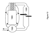
一般的には、炭素変換システムによる炭素変換プロセスは以下の通りである。原材料は一次プロセスユニット内で一般的に約800℃未満に加熱され、原材料の残留水分の除去と、原材料の炭素系成分の速やか且つ効率的な揮発が主要なプロセスである。結果として生成されるチャーを含む処理済み原材料は、二次プロセスユニット内でより高温(例えば約1000℃〜1200℃)に加熱され、処理済み原材料を完全にオフガスと灰または固形残渣に変換する更なる炭素変換が行われる。二次プロセスユニットから出た灰または固形残渣は溶融ユニット内でガラス化され、スラグになる。一次プロセス、二次プロセス、溶融ユニットで生成されたガスはガス改質ユニットで改質される。ガス改質ユニットは少なくとも1つのエネルギー源(例としてプラズマ源または熱源など)と、必要に応じて1つまたは複数の粒子分離装置(サイクロン式分離機など)から成る。改質ユニットに含むに適した他のエネルギー源の例として、電熱ヒーター、プラズマプルーム、水素バーナー、電子ビーム、レーザー、輻射ヒーターなどがある。 In general, the carbon conversion process by the carbon conversion system is as follows. Raw materials are typically heated to less than about 800 ° C. in the primary process unit, with the main processes being the removal of residual moisture from the raw materials and the rapid and efficient volatilization of the carbon-based components of the raw materials. The resulting treated raw material containing char is heated to a higher temperature (eg, about 1000 ° C. to 1200 ° C.) in the secondary process unit to further convert the treated raw material into off-gas and ash or solid residue. A carbon conversion is performed. Ash or solid residue from the secondary process unit is vitrified into a slag in the melting unit. The gas generated in the primary process, the secondary process, and the melting unit is reformed in the gas reforming unit. The gas reforming unit consists of at least one energy source (such as a plasma source or heat source as an example) and optionally one or more particle separators (such as a cyclonic separator). Examples of other energy sources suitable for inclusion in the reforming unit include electric heaters, plasma plumes, hydrogen burners, electron beams, lasers, radiant heaters and the like.
炭素変換システムの高温合成ガス産物は、さらなる清浄と調質を受ける前にオプションとして冷却段階を経ることができる。1つの実施形態では、炭素変換システムには炭素変換プロセスより生成された高温合成ガスを冷却する熱回収ユニットが備わっている。1つの実施形態では、熱回収ユニットは回収熱交換器である。このような実施形態では、回収熱交換器は顕熱を液体に伝える熱交換器を備えることができ、その熱を他所で利用できる。1つの実施形態では、熱回収ユニットは合成ガス対空気の熱交換器(一般的には回収熱交換器と呼ばれる)であり、これは高温合成ガスから顕熱を回収し外気に伝えることで熱風を提供する。この実施形態では、熱風はオプションとして一次プロセスユニットおよび/または二次プロセスユニットに通される。回収熱交換器はオプションとして熱回収蒸気発生器を含むかもしれず、これは例えば蒸気タービンの駆動に、または炭素変換システムのプロセス添加物として使用することができる。発明の実施形態の1つでは、炭素変換システムは高温合成ガスから顕熱を回収し一次プロセスユニットおよび/または二次プロセスユニットで再利用する合成ガス対空気の熱交換器を備えている。 The hot synthesis gas product of the carbon conversion system may optionally undergo a cooling step before undergoing further cleaning and tempering. In one embodiment, the carbon conversion system is equipped with a heat recovery unit that cools the hot synthesis gas produced from the carbon conversion process. In one embodiment, the heat recovery unit is a recovery heat exchanger. In such embodiments, the recovered heat exchanger can include a heat exchanger that transfers sensible heat to the liquid, and that heat can be utilized elsewhere. In one embodiment, the heat recovery unit is a synthesis gas-to-air heat exchanger (commonly referred to as a recovery heat exchanger), which recovers sensible heat from the hot synthesis gas and transfers it to the outside air to transfer hot air I will provide a. In this embodiment, hot air is optionally passed through the primary process unit and / or the secondary process unit. The recovery heat exchanger may optionally include a heat recovery steam generator, which can be used, for example, to drive a steam turbine or as a process additive for a carbon conversion system. In one embodiment of the invention, the carbon conversion system comprises a synthesis gas to air heat exchanger that recovers sensible heat from the hot synthesis gas and reuses it in the primary process unit and / or the secondary process unit.
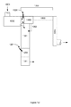
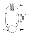
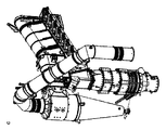
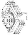
図1Aは、一次プロセスユニット(第1)、二次プロセスユニット(第2)、溶融ユニット(第3)とガス改質ユニット(第4)の4つの機能ユニットから成る炭素変換システムの実施形態を図示したものである。図にある通り、一次プロセスユニット1は二次プロセスユニット2に接続されており、それは溶融ユニット3に接続されている。ガス改質ユニット4は一次プロセスユニット1、二次プロセスユニット2、溶融ユニット3のそれぞれと運転的に接続している。炭素変換システムの実施形態によっては、ガス改質ユニットと他3つの機能ユニットのうちの1つとの運転的接続は、間接的または直接的なものと考えられる。
FIG. 1A shows an embodiment of a carbon conversion system comprising four functional units: a primary process unit (first), a secondary process unit (second), a melting unit (third), and a gas reforming unit (fourth). It is illustrated. As shown, the
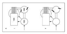
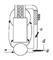
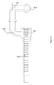
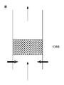
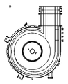
図1Bは、炭素変換システムの1つの実施形態を示す。この実施形態では、炭素変換システムはゾーンが複数ある、耐火物のライニングが施されたチャンバーから成る。このチャンバーは炭素系原材料を受け入れる流入口(1001)が1つまたは複数、合成ガス出口、スラグ出口、熱風用入り口が複数、オプションとしてサイクロン式分離機(1400)などの粒子分離装置、そして固形残渣を溶かしスラグに変えるほか、オフガスを改質するプラズマまたはその代替物の供給源がある。 FIG. 1B shows one embodiment of a carbon conversion system. In this embodiment, the carbon conversion system consists of a refractory-lined chamber with multiple zones. This chamber has one or more inlets (1001) for receiving carbon-based raw materials, multiple syngas outlets, slag outlets, multiple inlets for hot air, optional particle separators such as a cyclonic separator (1400), and solid residue There is a source of plasma or an alternative to modifying off-gas as well as melting slag.
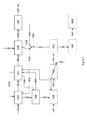
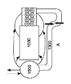
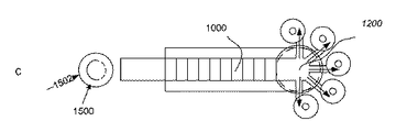
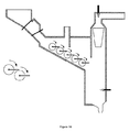
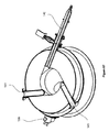
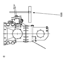
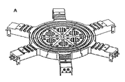
図1Cに示す炭素変換システムの1つの実施形態は、水平置き一次プロセスユニット(1000)、縦置き二次プロセスユニット(1201)とそれに付随する溶融ユニット(1250)、ガス改質ユニット(1300)と、オプションとして回収熱交換器(1500)から成る。ガス改質ユニットはプラズマ源またはそれに同等なものと、オプションとしてサイクロン式分離機(1400)から成る。サイクロン式分離機がある場合は、ガス改質ユニット内のガスはサイクロン分離の前、後、または最中に改質することができる。一部の実施形態のスラグ出口(1252)は顆粒化システム(1251)と運転的に連結している。 One embodiment of the carbon conversion system shown in FIG. 1C includes a horizontal primary process unit (1000), a vertical secondary process unit (1201) and an associated melting unit (1250), and a gas reforming unit (1300). , Optionally consisting of a recovered heat exchanger (1500). The gas reforming unit consists of a plasma source or equivalent and optionally a cyclonic separator (1400). If there is a cyclonic separator, the gas in the gas reforming unit can be reformed before, after, or during the cyclone separation. In some embodiments, the slag outlet (1252) is operatively connected to the granulation system (1251).
一般的には、炭素変換システムが行う炭素変換プロセス(ここでは「ガス化」ともいう)はさらに3段階に分割することができる。それはすなわち乾燥、揮発、チャーから灰への変換(炭素変換)である。 In general, the carbon conversion process (herein also referred to as “gasification”) performed by the carbon conversion system can be further divided into three stages. That is, drying, volatilization, char to ash conversion (carbon conversion).
第1段階 原料の乾燥
プロセスの第1段階は、主に25℃〜400℃で行われる乾燥である。このようなやや低い温度でも、部分的な揮発と炭素から灰への変換も発生することがある。
第2段階 原料の揮発
プロセスの第2段階は、主に400℃〜700℃で行われる揮発である。この温度では、残った少量の乾燥過程と一部の二次処理(チャーからオフガスへの変換)が行われる。
第3段階 炭素変換
プロセスの第3段階は600℃〜1000℃の温度範囲で行われる炭素変換である。この温度では、残った少量の揮発過程も行われる。この段階が終わると、ほとんど炭素を含まない固形残渣(灰)とオフガスが主に残る。
First Stage The first stage of the raw material drying process is drying performed mainly at 25 ° C to 400 ° C. Even at such slightly lower temperatures, partial volatilization and carbon to ash conversion may also occur.
Second Stage The second stage of the raw material volatilization process is volatilization mainly performed at 400 ° C to 700 ° C. At this temperature, a small amount of remaining drying process and some secondary treatment (char to off-gas conversion) are performed.
Third Stage The third stage of the carbon conversion process is carbon conversion performed in the temperature range of 600 ° C to 1000 ° C. At this temperature, the remaining small amount of volatilization process also takes place. At the end of this stage, a solid residue (ash) and off-gas containing almost no carbon remain.
以上のプロセスで所望の合成ガス産物の歩留まりを向上させるために、炭素系原料から所望のガス産物への変換の最大化が好ましい。従って炭素変換システムは原材料の利用可能な炭素を事実上完全に合成ガスに変換するほか、合成ガスとスラグを回収するシステムを提供する。様々な実施形態では、炭素変換システムはさらに炭素を所望の合成ガス産物に容易に変換できるように、熱風および/またはプロセス添加物(蒸気、または炭素に富むガス、または炭素、あるいはその組み合わせなど)の注入を提供する。炭素変換システムはさらに残留した無機材料(灰)を容易にガラス状物質またはスラグに完全に変換し、オフガスを精製および/または改質することで所望の合成ガスを生成できるようにプラズマまたはそれと同等のものを供給する。 In order to improve the yield of the desired synthesis gas product in the above process, it is preferable to maximize the conversion from the carbon-based raw material to the desired gas product. Thus, the carbon conversion system provides a system for recovering synthesis gas and slag as well as virtually completely converting the available carbon of the raw material into synthesis gas. In various embodiments, the carbon conversion system further allows hot air and / or process additives (such as steam or carbon rich gas, or carbon, or combinations thereof) to facilitate the conversion of carbon to the desired synthesis gas product. Providing injection. The carbon conversion system also easily converts the residual inorganic material (ash) into a glassy substance or slag easily, and the plasma or equivalent to produce the desired synthesis gas by purifying and / or modifying the off-gas Supply things.
炭素変換システムは統合化されたシステムとして原材料を乾燥、揮発、炭素変換、オフガス改質へと順次送ることで合成ガスの生成を容易にする。 The carbon conversion system is an integrated system that facilitates synthesis gas generation by sequentially feeding raw materials to drying, volatilization, carbon conversion, and off-gas reforming.
特に、一次プロセスユニットは主に原材料を乾燥し、炭素質成分を揮発するように設計されている。二次プロセスユニットは処理済みの原材料に残留した揮発性物質を除去し、チャーに残った炭素を有効利用するために、例えばさらに空気を注入し、付随している溶融ユニットの熱を利用し、滞留時間を設けることで炭素の回収を促進するように設計されている。 In particular, the primary process unit is mainly designed to dry the raw materials and volatilize the carbonaceous components. The secondary process unit removes volatiles remaining in the treated raw materials and, for example, injects more air and uses the heat of the associated melting unit to effectively utilize the carbon remaining in the char, Designed to promote carbon recovery by providing a residence time.
結果、2つの処理ユニットは2つの異なる種類のオフガスを形成する。一次プロセスユニットは揮発性物質、水蒸気とその他の水素化合物に富む高発熱ガスを提供するが、二次プロセスユニットは一酸化炭素と二酸化炭素を主に、水素ガス、重質炭素化合物と炭素煤を含むオフガスを生成する。 As a result, the two processing units form two different types of off-gas. The primary process unit provides a highly exothermic gas rich in volatile substances, water vapor and other hydrogen compounds, while the secondary process unit mainly contains carbon monoxide and carbon dioxide, hydrogen gas, heavy carbon compounds and carbon soot. Generate off gas containing.
オプションとして粒子分離装置が提供されるガス改質ユニットはガスに含まれる粒状物質を除去または削減し、ガスを合成ガスに改質する。粒子分離装置を含むことによって下流装置の詰まりと摩耗や劣化の軽減、粒状物質の悪影響の軽減、凝縮性タールがある場合の下流微粒子除去の必要の削減を補助することができる。 A gas reforming unit, optionally provided with a particle separator, removes or reduces particulate matter contained in the gas and reforms the gas into synthesis gas. Inclusion of a particle separator can help reduce clogging and wear and degradation of downstream devices, reduce the adverse effects of particulate matter, and reduce the need for downstream particulate removal when there is condensable tar.
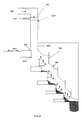
図4と図5では、炭素変換システムの1つの実施形態中の原材料とガスの移動と下流工程システムを詳述するブロックフロー図を示す。下流工程システムは回収熱交換器(1500)を含み、炭素系原料(1002)は炭素変換システムの一次プロセスユニット(1000)の中で水分を除去され、揮発成分は外気または冷気(1502と1504)を熱する回収熱交換器(1500)または多種燃料バーナーが提供する熱風(1505)の熱によって揮発され、チャーから成る処理済みの原材料を提供する(1003)。二次プロセスユニット(1201)は処理済みの原材料を一次プロセスユニット(1000)から受け入れ、処理済みの原材料を残渣(1206)とオフガス(1205)に変換する。図示された実施形態では、一次プロセスユニット(1000)と二次プロセスユニット(1201)からくるガス(1204・1205)は改質(1301)前のオフガスの微粒子含有量を低減するために、ガス改質ユニットのサイクロン式分離機(1400)に入る。微粒子含有量(1403)が低減されたオフガスは改質を受ける。改質ゾーンから出る高温合成ガス(1501)は回収熱変換機(1500)を通過し、ここで必要に応じて再利用のために顕熱が回収される。冷却された合成ガス(1501)はオプションとして下流ガス精製(1600)の段階で精製または清浄される。清浄および/または精製されたガスはエンジン(1602)で使用される前に適したタンク(1601)にて保管されるかもしれない。 4 and 5 show block flow diagrams detailing raw material and gas transfer and downstream process systems in one embodiment of a carbon conversion system. The downstream process system includes a recovery heat exchanger (1500), the carbon-based raw material (1002) is dehydrated in the primary process unit (1000) of the carbon conversion system, and volatile components are outside air or cold air (1502 and 1504) It is volatilized by the heat of the recovery heat exchanger (1500) or the hot air (1505) provided by the multi-fuel burner to provide the treated raw material consisting of char (1003). The secondary process unit (1201) receives processed raw materials from the primary process unit (1000) and converts the processed raw materials into residue (1206) and off-gas (1205). In the illustrated embodiment, the gases (1204 and 1205) coming from the primary process unit (1000) and the secondary process unit (1201) are gas modified to reduce the off-gas particulate content before reforming (1301). Enter the quality unit cyclone separator (1400). Off-gas with reduced particulate content (1403) undergoes modification. The high temperature synthesis gas (1501) exiting the reforming zone passes through a recovery heat converter (1500) where sensible heat is recovered for reuse as needed. The cooled synthesis gas (1501) is optionally purified or purified in the downstream gas purification (1600) stage. The cleaned and / or purified gas may be stored in a suitable tank (1601) before being used in the engine (1602).
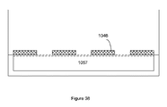
二次プロセスユニットからくる残渣(1206)、そして任意でサイクロン式分離機(1400)からくる微粒子(1402)は溶融ユニットにて溶融され、プラズマ源(1301)または同等のものからの加熱によって高温スラグ(1255)を生成する。高温スラグ(1255)はオプションとして顆粒化されるか、またはスラグ処理システム(1256)によってその他の処理をされ、冷却されたスラグ(1257)を提供する。スラグゾーンへの熱はプラズマ源(1301)と、オプションとして合成ガスまたは代わりの燃料(1254)を使用できる補助的多種燃料バーナー(1253)によって供給される。 Residue from the secondary process unit (1206) and optionally fine particles (1402) from the cyclonic separator (1400) are melted in the melting unit and heated to high temperature slag by heating from the plasma source (1301) or equivalent (1255) is generated. The hot slag (1255) is optionally granulated or otherwise processed by a slag treatment system (1256) to provide a cooled slag (1257). Heat to the slag zone is supplied by a plasma source (1301) and optionally an auxiliary multifuel burner (1253) that can use synthesis gas or alternative fuel (1254).
図6では、必要に応じて様々な段階でプロセス添加物がシステムに追加され、システム内でのプロセスを促進および/または原材料(1002)内の炭素の変換を促進することで所望の合成ガス産物にする。 In FIG. 6, process additives are added to the system at various stages as needed to facilitate the process within the system and / or promote the conversion of carbon in the raw material (1002) to achieve the desired syngas product. To.
炭素変換システムはさらに運転を調整する1つまたは複数の制御システムから成り、オプションとしてスラグ顆粒化ユニットおよび/または合成ガスから熱を回収する熱再利用ユニットを含むユニットが付随する。 The carbon conversion system further comprises one or more control systems that coordinate the operation, optionally accompanied by a unit that includes a slag granulation unit and / or a heat recycling unit that recovers heat from the synthesis gas.
原材料
現在の炭素変換システムでの使用に適した原材料は炭素を含んだ様々な材料を含む。適した原材料は都市固形廃棄物(MSW)を含む有害及び無害廃棄物、工業廃棄物、生物医療廃棄物、リサイクル負荷のプラスチックを含む再利用に不適切な炭素質材料、下水汚泥、石炭、重油、石油コークス、ビチューメン、重油精製の残渣、精製による廃棄物、炭素水素汚染された固形物、バイオマス、農業廃棄物、都市固形廃棄物、有害廃棄物と工業廃棄物を含むが、それだけに限らない。ガス化に有用なバイオマスの例としては廃木材、新鮮な木材、果物・野菜・穀物の加工の残渣、製紙工場の残渣、藁、草と肥料が含まれるが、それだけに限らない。
Raw materials Raw materials suitable for use in current carbon conversion systems include various materials containing carbon. Suitable raw materials include hazardous and non-hazardous waste including municipal solid waste (MSW), industrial waste, biomedical waste, carbonaceous materials unsuitable for reuse including recycled plastics, sewage sludge, coal, heavy oil Including, but not limited to, petroleum coke, bitumen, heavy oil refining residues, refining waste, carbon hydrogen contaminated solids, biomass, agricultural waste, municipal solid waste, hazardous waste and industrial waste. Examples of biomass useful for gasification include, but are not limited to, waste wood, fresh wood, fruit, vegetable and grain processing residues, paper mill residues, firewood, grass and fertilizer.
現在のシステムは使用される原材料の必要条件によって適応または変更することができる。例えば、炭素含有量が高い原材料を使用する場合、炭素変換システムは炭素含有量がより低い原材料が必要とするものより大きな二次プロセスユニットを含むように設計できる。あるいは、揮発性物質を多く含む原材料が使用される場合、炭素変換システムは揮発性物質がより少ない原材料が必要とするものより大きな一次プロセスユニットを含むように設計できる。 Current systems can be adapted or modified depending on the requirements of the raw materials used. For example, when using raw materials with a high carbon content, the carbon conversion system can be designed to include larger secondary process units than those required for raw materials with a lower carbon content. Alternatively, if raw materials rich in volatile materials are used, the carbon conversion system can be designed to include larger primary process units than those required by raw materials with less volatile materials.
現行の炭素変換システムは一次原料と1つまたは複数の二次原料の様々な混合比の混合物を使用するように適応できる。ここでは、二次原料はプロセス添加物として機能する原料であり、一次原料の炭素含有量を調整することで最終的に産出される合成ガスを一定に保つ。例えば、システムがバイオマスやMSWなどの炭素含有量の低い一次原料を使用する場合、石炭やプラスチックなどの高炭素二次原料を高炭素プロセス添加物として提供し、原料内の炭素の割合を増加させることができる。あるいは、石炭のような高炭素原料が一次原料である場合、炭素含有量がより低い二次原料(バイオマスなど)を提供することによって高炭素含有量を相殺することが考えられる。 Current carbon conversion systems can be adapted to use mixtures of primary feeds and one or more secondary feeds in various mixing ratios. Here, the secondary raw material is a raw material that functions as a process additive, and the synthesis gas finally produced is kept constant by adjusting the carbon content of the primary raw material. For example, if the system uses a low-carbon primary material such as biomass or MSW, provide a high-carbon secondary material such as coal or plastic as a high-carbon process additive to increase the proportion of carbon in the material. be able to. Alternatively, when a high carbon raw material such as coal is a primary raw material, it is conceivable to offset the high carbon content by providing a secondary raw material (such as biomass) having a lower carbon content.
複数の原材料が使用される場合、原材料は組み合わせられてから共用の原料注入口より一次プロセスユニットに注入されるか、専用の原材料取入口を通して個別に一次プロセスユニットに注入されることもある。 When multiple raw materials are used, the raw materials may be combined and then injected into the primary process unit through a common raw material inlet, or may be individually injected into the primary process unit through a dedicated raw material inlet.
原材料は必要であれば前処理される。例えば、原材料はシュレッダーなどの剪断装置を1回または複数回通過し、より小さい断片に加工されるかもしれない。さらに/または原材料を磁気分離機、渦電流選別装置、振動ふるい、エアナイフなどに通すことによって鉄やその他の再利用可能なものを取り除くかもしれない。 Raw materials are pretreated if necessary. For example, the raw material may pass through a shearing device such as a shredder one or more times and be processed into smaller pieces. In addition, iron and other reusable materials may be removed by passing the raw material through a magnetic separator, eddy current sorter, vibrating screen, air knife, or the like.
MSWが一次原料である実施形態では、原材料は選別によって有害またはエネルギー源としての見込みが少ない白物、マットレス、プロパンボンベなどの除去、材料の大きさを低減するための破砕、鉄類の分離、非鉄物質の除去、無機物とプラスチックの除去、または以上の組み合わせの前処理をされるかもしれない。 In embodiments where the MSW is the primary raw material, the raw material is removed by whitening, mattresses, propane cylinders, etc., which are less likely to be harmful or energy sources by sorting, crushing to reduce material size, separation of iron, Non-ferrous materials may be removed, inorganics and plastics may be removed, or a combination of these may be pretreated.
炭素変換システムの一次プロセスユニット
炭素変換システムの一次プロセスユニットは少なくとも炭素系原材料の乾燥と原材料の炭素質成分の揮発を行い、チャーから成る処理済み原材料を出力し、それは後に二次プロセスユニットでさらに処理される。
Primary process unit of the carbon conversion system The primary process unit of the carbon conversion system performs at least drying of the carbon-based raw material and volatilization of the carbonaceous components of the raw material, and outputs a treated raw material consisting of char, which is further processed by the secondary process unit. It is processed.
一次プロセスユニットは1つまたは複数の原材料取入口から成り、1つまたは複数の熱源と二次プロセスユニットに運転的に連結している。一次プロセスユニットはさらに材料をユニット内で移送するための横移動システムを備えている。炭素系原材料は1つまたは複数の原材料取入口を通して一次プロセスユニット内に入り、処理中に横移動システムによってユニット内を二次プロセスユニットに向かって移送される。 The primary process unit consists of one or more raw material inlets and is operatively connected to one or more heat sources and a secondary process unit. The primary process unit further comprises a lateral movement system for transferring material within the unit. The carbonaceous raw material enters the primary process unit through one or more raw material intakes and is transported through the unit toward the secondary process unit by a lateral movement system during processing.
発明の実施形態の1つでは、一次プロセスユニットはモジュール型横移動システムを備えている。モジュール型横移動システムは1つまたは複数のモジュールから成り、各モジュールは空気および/またはプロセス添加物(集約的に「プロセスガス」という)を供給するほか、材料を一次プロセスユニット内で移送することができる。 In one embodiment of the invention, the primary process unit comprises a modular lateral movement system. A modular lateral transfer system consists of one or more modules, each supplying air and / or process additives (collectively referred to as “process gases”) and transporting materials within the primary process unit Can do.
全体として炭素変換システム内では、乾燥、揮発、炭素変換を順次促進することでガス化プロセスを容易にする。これはガス化プロセスを空間的に拡大することで、乾燥を特定の温度範囲内で行なってから別のゾーンに材料を移送し、また別の温度範囲内で揮発を行うことによって達成される。処理済み原材料は二次プロセスユニットに移送され、別の温度範囲内でチャーから灰に変換できる。 Overall, in the carbon conversion system, the gasification process is facilitated by sequentially promoting drying, volatilization and carbon conversion. This is accomplished by spatially expanding the gasification process by drying within a certain temperature range, then transferring the material to another zone, and volatilizing within another temperature range. The treated raw material can be transferred to a secondary process unit and converted from char to ash within another temperature range.
一次プロセスユニットは2つ以上のゾーンから成り、ゾーン内の温度とプロセス添加物は独立に操作でき、オプションとして乾燥および/または揮発を促進するように最適化できる。1つの実施形態では、一次プロセスユニットには3つ以上の処理ゾーンが提供される。 The primary process unit consists of two or more zones, and the temperature and process additives in the zones can be operated independently and optionally optimized to promote drying and / or volatilization. In one embodiment, the primary process unit is provided with more than two processing zones.
処理の間は、原材料は第一端(以下「供給端」)の近位で一次プロセスユニットに注入され、ユニットの供給端から二次プロセスユニットとの接合部まで移送される。原材料が一次プロセスユニットを通過するに連れ揮発成分が揮発し、体積が減少し堆積の高さが縮み、結果として生成されるチャーから成る固形物は二次プロセスユニットに移送され、さらなる処理を受ける。 During processing, the raw material is injected into the primary process unit proximal to the first end (hereinafter “feed end”) and transferred from the supply end of the unit to the junction with the secondary process unit. As the raw material passes through the primary process unit, the volatile components volatilize, the volume is reduced and the deposition height is reduced, and the resulting solids of char are transferred to the secondary process unit for further processing. .
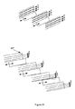
1つの実施形態では、一次プロセスユニットはステップ状のフロアを有し、多数の階またはステップがある。オプションとして、各階は傾斜している。1つの実施形態では、各階は約5〜約10度の角度に傾斜している。 In one embodiment, the primary process unit has a stepped floor and there are multiple floors or steps. As an option, each floor is inclined. In one embodiment, each floor is inclined at an angle of about 5 to about 10 degrees.
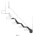
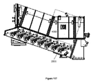
1つの実施形態では、一次プロセスユニットは多数の階があるステップ状フロアを有する。図20では、ステップの蹴り上げは出口に近くなるに連れて徐々に減少する。 In one embodiment, the primary process unit has a stepped floor with multiple floors. In FIG. 20, the step kick-up gradually decreases as it approaches the exit.
通気が妨害される可能性に配慮して、オプションとして傾斜したフロアセクションを使用しすることによって一次プロセスユニットを「伸ばす」ことができる。 The primary process unit can be “stretched” by using an optionally tilted floor section, taking into account the potential for airflow obstruction.
1つの実施形態では、一次プロセスユニットのフロアは全体的に二次プロセスユニットまたは供給端に向けて全体的に傾斜している。 In one embodiment, the primary process unit floor is generally inclined toward the secondary process unit or feed end.
オプションとして、各ステップは一体構造、ボックス型構造、または層型構造であるかもしれない。例えば、各ステップは鋳物または層型構造かもしれない。層型構造の実施形態では、各ステップは交互に金属とセラミックの層で形成されるかもしれない。 Optionally, each step may be a monolithic structure, a box-type structure, or a layered structure. For example, each step may be a cast or layered structure. In a layered structure embodiment, each step may be formed with alternating metal and ceramic layers.
図24の1つの実施形態では、各ステップは厚手の金属とセラミックブランケットが交互に重なる層から成る層型構造である。各金属層は一連のプレナムから成り、各プレナムには空気および/または蒸気を水平にチャンバー内に注入できるようにノズルが備わっている。空気は予め設定された速度と噴射侵入深さで注入される。必要に応じて低・中・高侵入で均等にガスを行き渡らせることができるように、様々な直径のノズルが提供される。 In one embodiment of FIG. 24, each step is a layered structure consisting of layers of alternating thick metal and ceramic blankets. Each metal layer consists of a series of plenums, each plenum being equipped with a nozzle so that air and / or steam can be injected horizontally into the chamber. Air is injected at a preset speed and injection penetration depth. Various diameter nozzles are provided so that gas can be distributed evenly with low, medium and high penetration as required.
1つの実施形態では、ステップ上の移動は横移動システムが容易にし、オプションとして各ステップに独立に制御された横移動ユニットを配備することができる。 In one embodiment, the movement on the steps is facilitated by a lateral movement system, and optionally an independently controlled lateral movement unit can be deployed at each step.
ステップ状フロアのある実施形態では、ドロップ回数と寸法は長さと滞留時間の要求を満たすものを選択できる。1つの実施形態では、最初は長いドロップ距離と比較的短い往復距離が使用され、終わりに向かうに連れて徐々により小さいドロップ距離と同じ移動距離(最初に物質が水平面に対し約60度であり、終わりには30度であることに相当)であるかもしれない。制御されない落下がなく、十分な混合を実現できるようドロップ高さを設計できる。 In an embodiment with a stepped floor, the number and size of drops can be selected to meet length and dwell time requirements. In one embodiment, a long drop distance and a relatively short round trip distance are used at the beginning, with the same travel distance as the drop distance gradually decreasing towards the end (initially the material is about 60 degrees to the horizontal plane, It may be equivalent to 30 degrees at the end). The drop height can be designed so that there is no uncontrolled drop and sufficient mixing is achieved.
1つの実施形態では、一次プロセスユニットは傾斜フロアを有する。 In one embodiment, the primary process unit has an inclined floor.
1つの実施形態では、一次プロセスユニットには内蔵バッフルが提供される。 In one embodiment, the primary process unit is provided with an internal baffle.
一次プロセスユニットの横移動システム
1つの実施形態では、一次プロセスユニットは横移動システムから成る。同実施形態では、横移動システムは1つまたは複数の横移動ユニットから成る。各横移動ユニットは移動要素とガイド要素または位置決めの要素または手段を備えている。移動要素には適切なガイド噛合要素が備えさせ得ることは、本技術に係る技術者には明確であろう。
Horizontal movement system of primary process unit
In one embodiment, the primary process unit comprises a lateral movement system. In the same embodiment, the lateral movement system consists of one or more lateral movement units. Each lateral movement unit comprises a moving element and a guide element or positioning element or means. It will be clear to those skilled in the art that the moving element can be provided with a suitable guide engagement element.
移動要素は様々は設計が可能であり、棚・台、プッシャーラムまたはキャリアラム、鋤、ねじ要素、グレート、コンベヤまたはベルトを含むが、それらに限定されない。ラムは単独ラムまたは多指型ラムを含むことができる。 The moving elements can be designed in various ways, including but not limited to shelves / bases, pusher rams or carrier rams, scissors, screw elements, greats, conveyors or belts. The ram can include a single ram or a multi-finger ram.
1つの実施形態では、ラムは行程毎に完全に引っ込めることができる短いラムである。 In one embodiment, the ram is a short ram that can be fully retracted from stroke to stroke.
1つの実施形態では、一次プロセスユニットは単独ラムまたは多指型ラムのどちらを使用するように設計されている。 In one embodiment, the primary process unit is designed to use either a single ram or a multi-finger ram.
1つの実施形態では、ラムの稼働中、ガスの流れの妨害を最小限に抑えることが好ましい場合には多指型ラムが使用される。 In one embodiment, a multi-fingered ram is used when it is desirable to minimize gas flow obstruction during ram operation.
多指型ラムの設計では、多指型ラムはユニタリー構造、またはラムフィンガーがラムの本体に取り付けてある構造であるかもしれず、各ラムフィンガーは位置によって幅が異なる。多指型ラムのフィンガーの間隔は、反応物の微粒子のブリッジングを防止するために設定されている。 In a multi-finger ram design, the multi-finger ram may be a unitary structure, or a structure where the ram fingers are attached to the ram body, with each ram finger having a different width depending on the position. The spacing between the fingers of the multi-finger type ram is set to prevent bridging of the reactant fine particles.
1つの実施形態では、各フィンガーの幅は約2〜3インチ、厚さは0.5〜1インチ、間隔は0.5〜2インチである。 In one embodiment, each finger is about 2-3 inches wide, 0.5-1 inch thick, and 0.5-2 inches apart.
1つの実施形態では、移動要素は「T字型」である。 In one embodiment, the moving element is “T-shaped”.
システムが極めて高温で稼働する一部の実施形態では、オプションとして移動要素を冷却することができる。冷却手段は外部または移動要素に組み込まれているかもしれない。ラムまたは棚を使用した実施形態では、ラムまたは棚の内部に冷却手段を提供することができる。冷却は、チャンバー外から流体(空気または水など)を注入し、ラムまたは棚内で循環させて行うことができる。 In some embodiments where the system operates at very high temperatures, the moving element can optionally be cooled. The cooling means may be incorporated in the external or moving element. In embodiments using rams or shelves, cooling means can be provided inside the rams or shelves. Cooling can be performed by injecting fluid (such as air or water) from outside the chamber and circulating it in a ram or shelf.
1つの実施形態では、移動要素は折りたたみのアームを有する鋤から成り、鋤が引き込まれるとき同アームをたたむことができる。 In one embodiment, the moving element consists of a heel with a folding arm, which can be folded when the heel is retracted.
1つの実施形態では、移動要素はコンベヤから成る。1つの実施形態では、移動要素はベルトまたは羽根付きチェーンコンベヤから成る。 In one embodiment, the moving element comprises a conveyor. In one embodiment, the moving element consists of a belt or vaned chain conveyor.
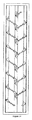
1つの実施形態では、歯車列が使用される。図25・26・27・28では、歯車式横移動ユニットは、物質を高温の反応ゾーンとの間の断熱材として機能する固形残渣の薄い層の上を移送することができる。時計回りに運転している時は、物質はつつかれながら移送される。反時計回りに運転している時は、物質は後ろに押されチャンバーフロアから退けられ、落下する。このように物質は重力と運動量によって前方そして下方に移送される。 In one embodiment, a gear train is used. In FIGS. 25, 26, 27, and 28, the geared lateral movement unit can transfer material over a thin layer of solid residue that acts as a thermal insulator between the hot reaction zones. When operating clockwise, the material is transported while being pocked. When driving counterclockwise, the material is pushed back, withdraws from the chamber floor, and falls. In this way, the substance is transferred forward and downward by gravity and momentum.
灰・チャーが少量落下する可能性があるが、スロット周辺のフロア高さを上げることによってこの影響は最小化できる。灰・チャーはオプションとして収集し再度一次プロセスユニットに(例えば、スクリューなどの使用によって)供給することができ、これは断熱材となる灰の層を維持する助けになる(灰が高温な場合、空気との接触を防ぐ必要がある)。 Although small amounts of ash / char can fall, this effect can be minimized by raising the floor height around the slot. Ashes and char can optionally be collected and re-supplied to the primary process unit (for example, by using screws), which helps maintain the ash layer that will be the insulation (if the ash is hot, Need to prevent contact with air).
1つの実施形態では、移動要素の駆動コンポーネントは他要素の外部にあり、オプションとしてグリースレスベアリングを使用するかもしれない。 In one embodiment, the drive component of the moving element is external to the other element and may optionally use a greaseless bearing.
移動要素の材料は高温での使用に適したものとする。このような材料は本技術に係る技術者にはよく知られており、ステンレス鋼、軟鋼、あるいは部分的にまたは全体に耐火物で保護された軟鋼を含む。移動要素はオプションとして鋳物または一体構造であるかもしれない。オプションとして、移動要素の大きさは様々な大きさおよび/または形の集塊を効果的に移送するように設計される。 The material of the moving element shall be suitable for use at high temperatures. Such materials are well known to those skilled in the art and include stainless steel, mild steel, or mild steel partially or wholly protected with a refractory. The moving element may optionally be a casting or a monolithic structure. Optionally, the size of the moving element is designed to effectively transfer agglomerates of various sizes and / or shapes.
移動要素用のガイド要素は一次プロセスユニット内部に位置するか、あるいは内付けされるかもしれない。もう1つの方法として、ガイド要素は一次プロセスユニットの外部に位置するか、あるいは外付けされるかもしれない。 The guide element for the moving element may be located inside the primary process unit or may be internal. Alternatively, the guide element may be located outside the primary process unit or may be external.
ガイド要素が内部に位置するか内付けの実施形態では、横移動システムは詰まりまたは破片の取り込みを防止するように設計できる。 In embodiments where the guide element is located internally or internally, the lateral movement system can be designed to prevent clogging or debris uptake.
ガイド要素が一次プロセスユニット外部に位置するか、または外付けの実施形態では、一次プロセスユニットは移動要素が入ることができる密閉可能な入り口を少なくとも1つ含む。 The guide element is located outside the primary process unit or, in an external embodiment, the primary process unit includes at least one sealable inlet through which the moving element can enter.
ガイド要素は一次プロセスユニットの側壁にある1つまたは複数のガイドチャネル、ガイドトラックまたはレール、ガイドトラフまたはガイドチェーンを含むことができる。 The guide elements can include one or more guide channels, guide tracks or rails, guide troughs or guide chains on the side walls of the primary process unit.
ガイド噛合部材はオプションとしてガイド要素と可動的に噛み合う1つまたは複数の車輪またはローラーを含むことができる。1つの実施形態では、ガイド噛合部材はガイドトラックに沿って滑走するように設計されたシューを備えている。オプションとして、シューはさらに交換可能な摩耗パッドを少なくとも1つ備えている場合がある。 The guide engagement member may optionally include one or more wheels or rollers that are movably engaged with the guide element. In one embodiment, the guide engagement member comprises a shoe designed to slide along the guide track. Optionally, the shoe may further include at least one replaceable wear pad.
1つの実施形態では、ガイド噛合要素は移動要素と一体化することができる。例えば、移動要素の表面はガイド要素と噛み合うように特別に設計されているかもしれない。1つの実施形態では、一次プロセスユニットのフロアはトラックを含んでおり、フロアと接触している移動要素はトラックと噛み合う形状に特別に設計されている。 In one embodiment, the guide meshing element can be integrated with the moving element. For example, the surface of the moving element may be specially designed to engage the guide element. In one embodiment, the floor of the primary process unit includes a track, and the moving element in contact with the floor is specifically designed to mesh with the track.
1つの実施形態では、移動要素の横位置は移動要素が一次プロセスユニットに入る位置でしか位置決めされていないが、移動要素の方向は位置決め要素によって常に正しく保たれている。従って複雑かつ正確なガイド機構の必要はなくなる。 In one embodiment, the lateral position of the moving element is only positioned at the position where the moving element enters the primary process unit, but the direction of the moving element is always kept correct by the positioning element. Therefore, the need for a complicated and accurate guide mechanism is eliminated.
1つの実施形態では、位置決め要素は共用のシャフトによって同期的に駆動する2つのチェーンである。チェーンは必要に応じて個々に調整でき、適切な位置決めを容易にする。 In one embodiment, the positioning element is two chains that are driven synchronously by a common shaft. The chains can be individually adjusted as needed to facilitate proper positioning.
1つの実施形態では、横移動システムは移動可能な棚・台である可能性があり、この場合物質は主に棚・台の上に乗って一次プロセスユニット内を移送される。物質のごく一部は移動可能の棚・台の先端によって押されるかもしれない。 In one embodiment, the lateral movement system can be a movable shelf / base, in which case the material is transported mainly in the primary process unit on the shelf / base. A small portion of the material may be pushed by the tip of a movable shelf / base.
1つの実施形態では、横移動システムがキャリアラムである可能性があり、この場合物質は主にキャリアラムの上に乗って一次プロセスユニット内を移送される。物質のごく一部はキャリアラムの先端によって押されるかもしれない。 In one embodiment, the lateral movement system may be a carrier ram, in which material is primarily transported over the carrier ram and into the primary process unit. A small portion of the material may be pushed by the tip of the carrier ram.
1つの実施形態では、横移動システムはプッシャーラムである可能性があり、この場合物質は主に一次プロセスユニット内を押されながら移送される。オプションとして、ラムの高さは移送される物質の深さとほとんど同じにすることができる。 In one embodiment, the lateral movement system can be a pusher ram, in which material is transferred primarily while being pushed through the primary process unit. Optionally, the height of the ram can be approximately the same as the depth of the material being transferred.
1つの実施形態では、横移動システムは一式のスクリューコンベヤである可能性がある。オプションとして、スクリューコンベヤは一次プロセスユニットのフロアにはめ込むことができ、空気の注入を妨害せずに物質を移送することができる。 In one embodiment, the lateral movement system can be a set of screw conveyors. As an option, the screw conveyor can be fitted into the floor of the primary process unit to transfer material without disturbing the air injection.
1つの実施形態では、横移動システムは移動グレートである。 In one embodiment, the lateral movement system is a moving great.
横移動システムの動力は1つまたは複数のモーターと駆動系によって提供でき、1つまたは複数のアクチュエータによって制御される。 The power of the lateral movement system can be provided by one or more motors and drive trains and is controlled by one or more actuators.
横移動ユニットのは必要に応じて専用のモーターから動力を得、個別のアクチュエータを有することができる。あるいは、1つまたは複数の横移動ユニットは1つのモーターと共用のアクチュエータによって動力を得るかもしれない。 The lateral movement unit can be powered by a dedicated motor as needed and can have separate actuators. Alternatively, one or more lateral movement units may be powered by a single motor and shared actuator.
本技術分野では、横移動システムの正確な動作を実現するための制御可能なモーターまたは回転運動装置は多様に存在し、横移動システムの推進に使用することができる。例として電動モーター、合成ガスまたはその他のガスを用いるモーター、蒸気を用いるモーター、重油とマイクロタービンを用いるモーターなどがあり、それらに限定されない。 In this technical field, there are various controllable motors or rotary motion devices for realizing the accurate operation of the lateral movement system, which can be used to propel the lateral movement system. Examples include, but are not limited to, electric motors, motors using synthesis gas or other gases, motors using steam, motors using heavy oil and micro turbines, and the like.
1つの実施形態では、モーターは可変速電動モーターであり、モーター出力軸の駆動を選択により順転または逆転とすることができる。必要に応じて、モーターとモーター出力軸の間にスリップクラッチを設けることができる。モーターはさらにギアボックスを備えているかもしれない。 In one embodiment, the motor is a variable speed electric motor, and the drive of the motor output shaft can be forward or reverse depending on selection. If necessary, a slip clutch can be provided between the motor and the motor output shaft. The motor may also have a gearbox.
横移動システムの運動は油圧システム、油圧ラム、チェーン&スプロケット駆動、またはラック&ピニオン駆動などの適切な駆動システムによって行われる。モーターの回転運動を直線運動に変換するこれらの手段は、ユニットの両側から同期させた状態で適用することができ、ユニットの方向を正常に保つことで機械的な故障の可能性を最小化できるという理由で有利である。 The movement of the lateral movement system is performed by a suitable drive system such as a hydraulic system, hydraulic ram, chain & sprocket drive, or rack & pinion drive. These means of converting the rotational motion of the motor into linear motion can be applied in a synchronized state from both sides of the unit, and the possibility of mechanical failure can be minimized by keeping the direction of the unit normal. This is advantageous.
1つの実施形態では、1つのラムにつき2本のチェーンを使用することによって精密なガイドの必要なしにラムの方向を適切に保つことができる。 In one embodiment, using two chains per ram allows the ram to be properly oriented without the need for precise guides.
1つの実施形態では、横移動システムは1つまたは複数の空気圧式ピストンを含む。 In one embodiment, the lateral movement system includes one or more pneumatic pistons.
1つの実施形態では、横移動システムは1つまたは複数の油圧ピストンを含む。 In one embodiment, the lateral movement system includes one or more hydraulic pistons.
横移動ユニットの外部に取り付けられた部分またはコンポーネントは、必要に応じて密閉されていない、または部分的に密閉された、あるいはは密閉された容器またはケーシングに保管される。容器はさらに整備の際に取り外し可能なカバーを備えているかもしれない。1つの実施形態では、容器の内圧は一次プロセスユニットの内部より高圧かもしれない。より高い内圧に達するには、窒素などが使用されるかもしれない。 The parts or components attached to the exterior of the lateral movement unit are stored in an unsealed, partially sealed or sealed container or casing as required. The container may further include a removable cover for servicing. In one embodiment, the internal pressure of the vessel may be higher than the interior of the primary process unit. Nitrogen etc. may be used to reach higher internal pressures.
一次プロセスユニット加熱システム
ガス化プロセスは熱を要する。加熱は、原材料の部分的な酸化により直接起こるか、既存技術の熱源をひとつまたは複数使用して間接的に行う。
Primary process unit heating system The gasification process requires heat. Heating occurs directly by partial oxidation of the raw material or indirectly using one or more existing heat sources.
発明のひとつの実施形態では、一次プロセスユニットはひとつまたは複数の熱源を含むか、ひとつまたは複数の熱源と協働する。熱源は利用に適したものが沢山あり、その中には熱風、水蒸気源、プラズマ源、電気ヒーターなどがある。熱は、一次プロセスユニットの床やユニット低部などの、ひとつまたは複数の決まった領域に供給されることもあり、一次プロセスユニット全体に供給されることもある。熱源の配置により、一次プロセスユニット内の処理を最適化することができる。例えば、乾燥ゾーンを加熱するように熱源を配置することで、乾燥プロセスを最適化できる。 In one embodiment of the invention, the primary process unit includes one or more heat sources or cooperates with one or more heat sources. There are many heat sources suitable for use, including hot air, water vapor source, plasma source, and electric heater. Heat may be supplied to one or more defined areas, such as the floor of the primary process unit, the lower part of the unit, or may be supplied to the entire primary process unit. Depending on the arrangement of the heat source, the processing in the primary process unit can be optimized. For example, the drying process can be optimized by placing a heat source to heat the drying zone.
ひとつの実施形態では、熱源が熱風を循環させる。熱風は、例えばエアボックス、空気ヒーター、熱交換器、回収熱交換器などにより供給することができ、これらはいずれも既存技術である。 In one embodiment, the heat source circulates hot air. Hot air can be supplied by, for example, an air box, an air heater, a heat exchanger, a recovery heat exchanger, and the like, all of which are existing technologies.
ひとつの実施形態では、独立したエアフィード・分配システムにより各ステップに熱風を提供する。オプションとして、熱風は水平方向、鉛直方向、またはその組み合わせにより供給することができる。既存技術に適切なエアフィード・分配システムがあり、それには各ステップレベルに個別のエアボックスを配し、ステップレベルの床にある穿孔からそのステップレベルへと熱風が通るようにしたものや、各ステップレベルに対し独立に制御されるスパージャーから熱風が送られるものが含まれる。 In one embodiment, an independent air feed and distribution system provides hot air for each step. Optionally, the hot air can be supplied in a horizontal direction, a vertical direction, or a combination thereof. There is an air feed / distribution system suitable for existing technology, which includes a separate air box for each step level, with hot air passing from the perforations on the step level floor to that step level, This includes hot air sent from a sparger controlled independently to the step level.
ひとつの実施形態では、各フロアレベルにひとつまたは複数の溝が各ステップの長尺方向に入っている。溝は熱風や水蒸気用パイプが入る大きさに設計されている。パイプは、オプションとして下3分の1から下半分が穿孔されており、ステップの長尺方向にわたり熱風または水蒸気が一様に散布されるようになっている。また、スパージャーパイプをパイプ上端に向けて穿孔することもできる。 In one embodiment, each floor level has one or more grooves in the lengthwise direction of each step. The groove is designed to be large enough to accommodate hot air and steam pipes. The pipe is optionally perforated from the lower third to the lower half so that hot air or water vapor is evenly distributed over the length of the step. It is also possible to drill the sparger pipe toward the upper end of the pipe.
ひとつの実施形態では、穿孔数が材料全体にわたり熱を循環させるように設計されている。 In one embodiment, the number of perforations is designed to circulate heat throughout the material.
ひとつの実施形態では、エアフローシステムが鋳造・成形されたインサートに組み込まれる。 In one embodiment, an airflow system is incorporated into the cast and molded insert.
各ステップが鋳造される実施形態では、プレナムをステップに組み込んで鋳造することができる。プレナムへの空気は、ヘッダー空間に熱風を供給する熱風システムから送り込むことができる。 In embodiments where each step is cast, the plenum can be incorporated into the step and cast. Air to the plenum can be fed from a hot air system that supplies hot air to the header space.
オプションとして、空気の注入のために複数のプレナムを設置し、場所により異なる流量の空気を注入することで一様かつ制御された空気配分も実現することもできる。実施形態には、1ステップ当り三つ以上のプレナムを設置するものもある。 Optionally, a plurality of plenums may be installed for air injection, and uniform and controlled air distribution can be achieved by injecting air at different flow rates depending on the location. In some embodiments, more than two plenums are installed per step.
ひとつの実施形態では、予め設計された(それぞれ異なる)注入速度と、ラムの行程やその他の障害物から十分離れたジェット注入深さで注入し、液化無しで一様であり途切れ・妨げのない空気の分配を実現する。 In one embodiment, the injection is performed at a pre-designed (different) injection speed and jet injection depth sufficiently away from the ram stroke and other obstacles, and is uniform without liquefaction and uninterrupted Realize air distribution.
様々な直径のノズルにより小・中・大流量を得る事で、廃棄物の領域をより一様にカバーするため、必要に応じ注入深さを低・中・高とする事ができる。 By obtaining small, medium and large flow rates with nozzles of various diameters, the waste area can be covered more uniformly, so that the injection depth can be made low, medium and high as required.
ひとつの実施形態では、熱風を高湿度熱風とする事ができる。 In one embodiment, the hot air can be high humidity hot air.
ひとつの実施形態では高温砂を循環させ熱源とする事ができる。 In one embodiment, hot sand can be circulated to serve as a heat source.
ひとつの実施形態では電気ヒーターまたは電気発熱体を熱源とする事ができる。 In one embodiment, an electric heater or an electric heating element can be used as a heat source.
ひとつの実施形態では、エアボックスから熱風を送る。ひとつの実施形態では高温の再生合成ガスがエアボックスを通し供給される。オプションとしてエアボックスは鋳造・成形されたユニタリー・インサートとすることができる。 In one embodiment, hot air is sent from an air box. In one embodiment, hot regeneration synthesis gas is supplied through an air box. As an option, the air box can be a cast and molded unitary insert.
ひとつの実施形態では、反りを減らすためにエアボックスを個別の反りを減らすためエアボックスは頑丈かつ重厚な鉄鋼製で、途切れ/妨げのない気流が発生する箇所にだけ熱風を注気する事ができる。 In one embodiment, the air box is made of strong and heavy steel to reduce individual warpage to reduce warpage, and hot air can be injected only where there is an uninterrupted / unobstructed airflow. it can.
ひとつの実施形態では、熱風の注入箇所は、高い注入ポートを利用してチャンバーの床より少し高いところに配置される。 In one embodiment, the hot air injection site is located slightly above the chamber floor using a high injection port.
一次プロセスユニットのプロセス添加物インプット
原材料をオフガスに効率よく変換するため、一次プロセスユニットにオプションとしてプロセス添加物を加えることができる。添加物の注入口の配置により、一次プロセスユニット内で行われる処理の最適化を助けることができる。例えば、揮発ゾーンに水蒸気や空気を供給するように添加物注入口を配置することで、揮発プロセスの最適化を助ける事ができる。
Process additive input in the primary process unit Process additives can optionally be added to the primary process unit to efficiently convert the raw material to off-gas. The placement of the additive inlet can help optimize the processing performed within the primary process unit. For example, arranging the additive inlet to supply water vapor or air to the volatilization zone can help optimize the volatilization process.
例えば、水蒸気注入により自由酸素や水素が十分に供給されるようにして、分解された原材料からオフガスや無害化合物への変換を最大化できる。また、空気注入により、処理における化学平衡を助け、燃料ガスの二次処理を最大化(自由炭素を最小化)し、熱入力のコストを最小化しつつ処理温度を維持すこともできる。 For example, free oxygen and hydrogen can be sufficiently supplied by water vapor injection to maximize the conversion of decomposed raw materials into off-gas and harmless compounds. In addition, air injection can help chemical equilibration in the process, maximize the secondary treatment of the fuel gas (minimize free carbon), and maintain the process temperature while minimizing the cost of heat input.
オプションとして、その他の添加物を使用し、オフガスを改善することもできる。 Optionally, other additives can be used to improve offgas.
ひとつの実施形態では、ユニット内に存在する酸素量が制限されるよう添加物の供給状況が監視される。酸素が不足した環境を実現することで、ジオキサン類やフラン類などの有害物質の発生を防ぐことができる。 In one embodiment, the supply status of the additive is monitored to limit the amount of oxygen present in the unit. By realizing an oxygen-deficient environment, generation of harmful substances such as dioxanes and furans can be prevented.
従って、一次プロセスユニットにはひとつまたは複数のプロセス添加物の注入口を設けることができ、これには水蒸気や空気の注気が含まれる。水蒸気の注入口は、例えば高温領域に水蒸気を送るように配置することができる。また、空気の注入口は、例えば一次プロセスユニットやその周辺に配置し、処理ゾーン全域にプロセス添加物が行き渡るようにすることができる。 Accordingly, the primary process unit may be provided with one or more process additive inlets, including the insufflation of water vapor or air. The water vapor inlet can be arranged to send water vapor to a high temperature region, for example. In addition, the air inlet can be disposed, for example, in the primary process unit or the vicinity thereof, so that the process additive can be distributed over the entire processing zone.
ひとつの実施形態では、プロセス添加物注入口が一次プロセスユニットの床近くに配置される。 In one embodiment, the process additive inlet is located near the floor of the primary process unit.
ひとつの実施形態では、床近くに配置されたプロセス添加物注入口は、耐火層の床に埋め込まれた半パイプ型エアスパージャーである。このようなエアスパージャーは、反応物の横移動への影響を最小化しつつ交換・整備・変更がやりやすいように設計できる。エアスパージャーの空気孔の数・直径・配置はシステムの要求や横移動システムの設計に合わせ変化をつけることができる。 In one embodiment, the process additive inlet located near the floor is a half-pipe air sparger embedded in the floor of the refractory layer. Such an air sparger can be designed to be easy to replace, maintain and change while minimizing the impact on the lateral movement of the reactants. The number, diameter, and arrangement of air sparger air holes can be varied to meet system requirements and lateral movement system design.
ひとつの実施形態ではプロセス添加物注入口は一次プロセスユニット床に設置される。このような添加物注入口は微粒子による詰まりを防止する設計であったり詰まり防止のための付属部品がついている。オプションとして、プロセス添加物注入口はプロセス添加物を注入するための様々な配置の孔を設けることができる。孔の配置はシステムの要求や横移動システムの設計に合わせ様々なものを使用できる。空気孔の配置を選択するに当り考慮すべき因子には、ベッドの液化を起こす高速の防止、耐火物の壁に沿って空気が導かれるのを防ぐため一次プロセスユニットの壁や端にあまり近く孔を配置しないこと、運動学的配慮から孔どうしの間隔を高々原材料のおおよその定格直径(2インチ)とすることなどがある。 In one embodiment, the process additive inlet is located on the primary process unit floor. Such an additive injection port is designed to prevent clogging by fine particles or has an accessory for preventing clogging. Optionally, the process additive inlet can be provided with various arrangements of holes for injecting process additive. Various hole arrangements can be used according to the system requirements and the design of the lateral movement system. Factors to consider when choosing the air hole arrangement include the high speed prevention of bed liquefaction and the proximity of the primary process unit walls and edges to prevent air from being routed along the refractory walls. There are no holes, and the kinematic consideration is to make the distance between the holes at most approximately the nominal diameter of the raw material (2 inches).
ひとつの実施形態では、空気孔は、横移動システムの動作が注気の流路を妨げないように配置される。 In one embodiment, the air holes are arranged such that operation of the lateral movement system does not interfere with the air flow path.
多指型ラムを使用するひとつの実施形態では、加熱された状態で空気孔が指の間(つまり間隙の部分)に来て、相互にずれた矢印模様の状態となる空気孔配置である。あるいは、空気孔の配置を覆われる孔と覆われない孔があり、均一な分配が最大化(つまり、空気の注入が無い床面積が最小化)されるハイブリッド型とすることもできる。 In one embodiment using a multi-fingered ram, the air hole arrangement is such that the air holes come between the fingers (i.e., the gaps) in the heated state, resulting in an offset arrow pattern. Alternatively, the arrangement of the air holes may be a hybrid type in which there are holes that are covered and holes that are not covered, and the uniform distribution is maximized (that is, the floor area without air injection is minimized).
ひとつの実施形態では、材料の横移動に対する影響・抵抗を最小化しつつ、プロセス添加物が大きな表面積上に均一に分配されるように孔が配置されている。 In one embodiment, the holes are arranged so that process additives are evenly distributed over a large surface area while minimizing the impact and resistance to lateral movement of the material.
ひとつの実施形態では、プロセス添加物の注入口が、プロセス添加物を低速で拡散した状態で供給する。 In one embodiment, the process additive inlet delivers the process additive in a slowly diffused state.
チャンバーを熱風で加熱する実施形態では、オプションとして追加の空気/酸素注入口を提供することができる。 In embodiments where the chamber is heated with hot air, an additional air / oxygen inlet can optionally be provided.
モジュラー横移動システム
モジュラー横移動システムは、ひとつまたは複数のモジュールから成り、各モジュールは一次プロセスユニットの中で反応物を移動させつつプロセスガスを供給する能力を有する。モジュラーの設計により、操作者はシステムのモジュールを取り外し、交換することができ、整備中に必要となるユニットの休止時間を大幅に最小化することができる。
Modular lateral movement system The modular lateral movement system consists of one or more modules, each module having the ability to supply process gas while moving reactants in the primary process unit. The modular design allows the operator to remove and replace system modules, greatly minimizing unit downtime required during maintenance.
各モジュールは、一次プロセスユニットと交換可能であるように設計されている。従ってユニットにはモジュールを設置できる挿入箇所が一つまたは複数あり、それぞれの挿入箇所には運転接続システムが付随している。同接続システムはモジュールが所望の機能を果たすために必要なシステムや供給源への接続をモジュールに対し提供する。例えば、運転接続システムは電源、プロセス添加物の供給源、空気源、水蒸気源、制御システム、合成ガス供給系などへの接続のうち一つまたは複数の組み合わせを含むことができる。実施形態によっては、一次プロセスユニット内の各挿入箇所は特定の接続を組み合わせて提供するように設定する事ができるが、その接続の組み合わせはユニットの動作、または同挿入箇所に挿入されるモジュール、もしくはその両方に依存するかも知れない。また、挿入箇所に接続が全て揃っており、各接続を使用するか否かはその挿入箇所に挿入されるモジュールの状態によって決まるような実施形態も可能である。 Each module is designed to be interchangeable with the primary process unit. Accordingly, the unit has one or more insertion points where the module can be installed, and each insertion point is accompanied by an operation connection system. The connection system provides the module with connections to the systems and sources necessary for the module to perform its desired function. For example, the operational connection system may include one or more combinations of connections to a power source, a process additive source, an air source, a water vapor source, a control system, a synthesis gas supply system, and the like. In some embodiments, each insertion point in the primary process unit can be set to provide a combination of specific connections, but the combination of connections is the operation of the unit, or a module that is inserted into the insertion point, Or it may depend on both. Further, an embodiment in which all the connections are prepared at the insertion location and whether or not to use each connection is determined by the state of the module inserted at the insertion location is possible.
上記の通り、各モジュールには一次プロセスユニット内で材料を移送するほか、プロセスガスを供給する機能も備わっている。従って、各モジュールにはモジュールの横移動システムが備わっており、材料を最初の位置から次の位置、またはその方向に移動させるように設計されている。さらに、各モジュールにはプロセスガス供給システムがひとつまたは複数個備わっており、そのプロセスガス供給システムは少なくとも部分的にプロセスガスを材料に供給するようになっている。プロセスガスの例として、空気、プロセス添加ガス、水蒸気、合成ガスなどがある。 As described above, each module has a function of supplying a process gas in addition to transferring materials in the primary process unit. Each module is therefore equipped with a lateral movement system for the module, which is designed to move the material from the first position to the next position or in that direction. In addition, each module is provided with one or more process gas supply systems, which process gas supply systems are adapted to at least partially supply process gas to the material. Examples of process gases include air, process additive gas, water vapor, synthesis gas, and the like.
実施形態ではモジュールにモジュール補助システムも備わっており、それはモジュールの横移動システムとプロセスガス供給システムの両方を補助する。補助システムはさらに、モジュールが運転接続する一次プロセスユニットとの相互接続のメカニズムをも備えることができる。相互接続のメカニズムは、例えば構造形状に基づき、メカニズムと一次プロセスユニットの挿入箇所が物理的にはまり合うように設計できる。別の例では、相互接続のメカニズムにモジュールを固定・保持するシステムを作り込むことができ、その場合、モジュールが挿入箇所に挿入されると、同固定システムがモジュールを挿入箇所の位置に固定する。 In an embodiment, the module also includes a module auxiliary system, which assists both the lateral movement system of the module and the process gas supply system. The auxiliary system may further comprise an interconnection mechanism with the primary process unit that the module is in operational connection with. The interconnection mechanism can be designed based on, for example, the structure shape so that the mechanism and the insertion point of the primary process unit fit physically. In another example, a system can be built that secures and holds the module in the interconnection mechanism, in which case, when the module is inserted into the insertion location, the fixation system secures the module at the location of the insertion location. .
一部の実施形態では、一次プロセスユニットの挿入箇所にモジュールが挿入されると、モジュールは自動的かつ物理的にユニットの運転接続システムに相互接続される。例えば、モジュールが挿入されると、電源、プロセスガス供給源やその他の供給源と物理的に自動位置決めが行われるように運転接続システムを設計できる。一部の実施形態では、ユニットの運転接続システムとモジュールの相互接続には能動的な接続が必要となる。能動的な接続は例えば、はまり合うパイプまたは電気コネクタを接続する事で行う。一部の実施形態では、一次プロセスユニット内の運転接続システムとモジュールとの相互接続は自動的接続と能動的接続の組み合わせである。 In some embodiments, when a module is inserted at the insertion point of the primary process unit, the module is automatically and physically interconnected to the unit's operational connection system. For example, an operational connection system can be designed such that when a module is inserted, physical automatic positioning is performed with a power source, process gas supply, and other sources. In some embodiments, the unit's operational connection system and module interconnection require an active connection. For example, active connection is performed by connecting fitting pipes or electrical connectors. In some embodiments, the interconnection of operational connection systems and modules within the primary process unit is a combination of automatic and active connections.
実施形態では、モジュールは一次プロセスユニット内の材料の横移動を行うほか、空気などのプロセス添加物も供給するように設計されている。実施形態では、モジュールは一次プロセスユニットの内壁に挿入するために特別に設計された多機能カートリッジとして構成されている。オプションとして、同カートリッジは速やかに交換できるように設計することもでき、そのときカートリッジのコンポーネントとユニットまたはシステムのコンポーネント(例えば、熱風供給源、プロセス添加物供給源、電源、制御システムなど)を速やかに接続するシステムを内蔵する。 In an embodiment, the module is designed to provide lateral movement of material within the primary process unit as well as supply process additives such as air. In an embodiment, the module is configured as a multi-function cartridge specially designed for insertion into the inner wall of the primary process unit. As an option, the cartridge can also be designed to be replaced quickly, at which time the cartridge components and unit or system components (eg, hot air source, process additive source, power source, control system, etc.) can be quickly Built-in system to connect to.
一部の実施形態では、モジュールの横移動システムと空気を供給するプロセスガス供給システムがひとつまたは複数、モジュールに備わっている。この実施形態では、プロセスガス供給システムはひとつまたは複数のエアボックスとして構成されている。一部の実施形態では、モジュールにはモジュールの横移動システムと、ひとつまたは複数のプロセス添加物を供給するプロセスガス供給システムが含まれる。一部の実施形態では、モジュールにはモジュールの横移動システムと、ひとつまたは複数のプロセス添加物と空気を供給するプロセスガス供給システムが含まれる。 In some embodiments, the module includes one or more module lateral movement systems and a process gas supply system that supplies air. In this embodiment, the process gas supply system is configured as one or more air boxes. In some embodiments, the module includes a lateral movement system of the module and a process gas supply system that supplies one or more process additives. In some embodiments, the module includes a lateral movement system of the module and a process gas supply system that supplies one or more process additives and air.
実施形態では、一次プロセスユニットの壁のスロットまたは穴の形をした挿入箇所に各モジュールを受け入れるように設計されている。実施形態では、複数のモジュールを挿入する場合には一次プロセスユニットの壁に複数のスロットまたは穴を設けることができる。オプションとして、壁のスロットまたは穴は、複数のモジュールを受け入れるように個々に設計できる。一部の実施形態では、隣接したカートリッジがそれぞれユニットの反対側から挿入されるように一次プロセスユニットが設計されている。一部の実施形態では、壁のスロットまたは穴がモジュールの挿入を必要としない場合、そのスロットに栓その他の封孔処理が提供されるかも知れない。 In an embodiment, it is designed to receive each module in an insertion point in the form of a slot or hole in the wall of the primary process unit. In embodiments, multiple slots or holes may be provided in the primary process unit wall when multiple modules are inserted. Optionally, the wall slots or holes can be individually designed to accept multiple modules. In some embodiments, the primary process unit is designed such that adjacent cartridges are each inserted from the opposite side of the unit. In some embodiments, if a wall slot or hole does not require insertion of a module, the slot may be provided with a plug or other sealing treatment.
実施形態では、モジュールをひとつまたは複数設置すると、それは一次プロセスユニットのフロアの少なくとも一部を構成する。床がステップ状フロアとして設計された一部の実施形態では、各モジュールはステップ状フロアの1ステップとなるように設計され、姿勢設定される。 In an embodiment, when one or more modules are installed, they constitute at least part of the floor of the primary process unit. In some embodiments where the floor is designed as a stepped floor, each module is designed and configured to be one step of the stepped floor.
一部の実施形態では、カートリッジとして構成された各モジュールが全て設置されると、各カートリッジの一部はその上にあるカートリッジに覆われ、一次プロセスユニット内部には一部しか露出しない。一番上のカートリッジが挿入されるスロットはユニット内部にカートリッジの一部しか露出しないように特別に設計されている。設置済みのカートリッジはステップ状フロアまたは、オプションとして傾斜したステップフロアも構成でき、材料の移動を促進するほか、未処理物の転がりを少なくとも部分的に抑制する。 In some embodiments, once all of the modules configured as cartridges are installed, a portion of each cartridge is covered by an overlying cartridge and only a portion is exposed inside the primary process unit. The slot into which the top cartridge is inserted is specially designed so that only a part of the cartridge is exposed inside the unit. The installed cartridge can also be configured as a stepped floor or, optionally, an inclined stepped floor, which facilitates material movement and at least partially inhibits unrolled material from rolling.
実施形態では、モジュールどうし、またはモジュールと一次プロセスユニットとの間にシールがなされる場合があり、それはユニット内外、もしくはモジュール間の物質・ガスの放出・混入を防ぐシール方法となる。一部の実施形態では、耐高温シリコーン、耐温ガスケット、その他の適当なシール装置を使用してモジュールを特定位置でシーリングすることができる。一部の実施形態では、ひとつまたは複数のモジュールのシーリングにおいて、モジュールを容易に取り出し、新品または修理済みのモジュールを挿入できるように適したシール方法が選択される。 In the embodiment, a seal may be provided between modules or between a module and a primary process unit. This is a sealing method for preventing release / mixing of substances / gas inside / outside the unit or between modules. In some embodiments, the module can be sealed at a specific location using high temperature silicone, temperature resistant gaskets, or other suitable sealing devices. In some embodiments, in sealing one or more modules, a suitable sealing method is selected so that the modules can be easily removed and new or repaired modules can be inserted.
一部の実施形態では、モジュールはボルト、ねじなどの止め具のうちひとつまたは複数の組み合わせを用いて定位置に取り外し可能な形で固定される。オプションとして、モジュールを摩擦力で一次プロセスユニットの壁の所望の位置に固定できる。一部の実施形態では、一次プロセスユニットの壁に付随している挿入箇所は、挿入・位置決めをする装置、接合プレート、シール材をひとつまたは複数含むことがある。 In some embodiments, the module is removably secured in place using one or more combinations of fasteners such as bolts, screws, and the like. Optionally, the module can be fixed to a desired position on the wall of the primary process unit with frictional forces. In some embodiments, the insertion point associated with the wall of the primary process unit may include one or more insertion / positioning devices, joining plates, and seals.
一部の実施形態では、一次プロセスユニットは1種類または複数種類のモジュールを受け入れるように設計できる。モジュールは様々な大きさ・形態で、一次プロセスユニット内での使用法・配置、またはユニット自体の形態に従って特別に適応したものとすることができる。 In some embodiments, the primary process unit can be designed to accept one or more types of modules. Modules can be of various sizes and forms and specially adapted according to usage / arrangement within the primary process unit or according to the form of the unit itself.
実施形態では、モジュールはチャンバー内の材料の横移動と空気または別のプロセス添加物をひとつまたは複数提供するように設計されている。同実施形態では、モジュールにはさらにサポートフレームワークまたはサポートシステムが備わっており、それはモジュールの構造を与えるほか、横移動システムと空気・添加物の供給システムの両方を補助するように設計されている。さらに、モジュールはチャンバー壁へのカートリッジ設置・位置固定や、要素の断熱を容易にするシーリングシステムまたは接続システムも備えている物もある。 In an embodiment, the module is designed to provide lateral movement of material within the chamber and one or more of air or another process additive. In this embodiment, the module is further equipped with a support framework or support system, which provides the structure of the module and is designed to assist both the lateral movement system and the air / additive supply system. . In addition, some modules are also equipped with a sealing or connection system that facilitates cartridge placement and positioning on the chamber walls and thermal insulation of the elements.
実施形態では、モジュールのサポートフレームワークは軟鋼、高炭素鋼、調質鋼、合金など、稼働環境に対し少なくとも部分的に耐性のある様々な建材により構築することができる。さらに、サポートフレームワークは設置と取り外しを容易にするように、例えば設置と取り外しに使用されるツールの取り付け場所、または隙間を有する設計とすることもできる。 In an embodiment, the module support framework may be constructed from a variety of building materials that are at least partially resistant to the operating environment, such as mild steel, high carbon steel, tempered steel, and alloys. Further, the support framework may be designed to facilitate installation and removal, for example, a mounting location for a tool used for installation and removal, or a design with a gap.
一部の実施形態では、モジュールに付随する横移動システムはモジュールの基部上を移動するように設計されている。この実施形態では、空気またはプロセス添加物は、プロセスガス供給システムの一部を形成するモジュールの基部または反応物の堆積の底から入ることができる。つまりプロセスガス供給システムは反応物の堆積を支える機能と、ユニットのフロアとしての機能を併せ持つものであり、反応物は横移動システムによって、ユニット内部に露出しているプロセスガス供給システムの表面上(供給面)を移送される。実施形態では、プロセスガス供給面はプロセスガス供給システムの上面である。プロセスガスの供給面は側面、端面、傾斜端面などがあり得る。実施形態では、プロセスガス供給システムの設計はモジュールの横移動システムの設計に従って少なくとも部分的に規定される。 In some embodiments, the lateral movement system associated with the module is designed to move over the base of the module. In this embodiment, air or process additive can enter from the base of the module or the bottom of the reactant deposit that forms part of the process gas supply system. In other words, the process gas supply system has both the function of supporting the deposition of reactants and the function of the unit floor, and the reactants are exposed on the surface of the process gas supply system exposed inside the unit by the lateral movement system ( Transported). In an embodiment, the process gas supply surface is the top surface of the process gas supply system. The process gas supply surface may be a side surface, an end surface, an inclined end surface, or the like. In an embodiment, the design of the process gas supply system is at least partially defined according to the design of the module lateral movement system.
一部の実施形態では、カートリッジ個体が補助・接続要素と機能要素の両者を備えている。補助・接続要素は、モジュールの構造体と、一次プロセスユニットの外殻への接続を密封するために特別に設計された1つまたは複数個の接続プレートを含む。熱損失と接続プレートのへの伝熱を防ぐために、モジュールの構造体と接続プレートの間に耐火物を提供することもある。挿入後、適切な固定具を使用してモジュールを固定することができる。モジュール構造体は、一次プロセスユニットの壁に正しく挿入し易くするために、位置決めガイドも含んでおり、またモジュールの挿入・取り外しを容易にするために、ツールを挿入できる隙間も含む。 In some embodiments, the cartridge individual includes both auxiliary and connecting elements and functional elements. The auxiliary and connection elements include the structure of the module and one or more connection plates specially designed to seal the connection to the outer shell of the primary process unit. In order to prevent heat loss and heat transfer to the connection plate, a refractory may be provided between the module structure and the connection plate. After insertion, the module can be secured using suitable fasteners. The module structure also includes a positioning guide to facilitate proper insertion into the wall of the primary process unit, and also includes a gap through which tools can be inserted to facilitate module insertion and removal.
モジュール横移動システム
各モジュールは、ひとつのモジュール横移動システムで構成される。これは、最初の位置から、2番目の位置に対しあるいは2番目の位置に向けて材料を移動するよう設定されている。複数の実施形態によると、モジュール横移動システムはひとつ又は2つ以上の移動要素及び、ひとつ又は2つ以上の駆動要素で構成される。横移動システムは、選択肢として、ひとつ又は2つ以上の移動要素の移動をガイドすることのできるガイドあるいは位置決め要素を含む。いくつかの実施形態によると、モジュール横移動システムはさらに、2つあるいはそれ以上のガイド噛合要素を含み、これはガイド要素と噛み合い、間での物理的に移動可能な相互接続ができるように設定されている。これにより、ひとつ又は2つ以上の移動要素の希望する方向への移動の保持が容易となり、また移動の度合いも希望通りにすることが可能となる。
Module lateral movement system Each module is composed of one module lateral movement system. This is set to move material from the first position to the second position or toward the second position. According to embodiments, the module lateral movement system is composed of one or more moving elements and one or more driving elements. The lateral movement system optionally includes a guide or positioning element that can guide the movement of one or more moving elements. According to some embodiments, the modular lateral movement system further includes two or more guide engagement elements that are configured to engage the guide elements and provide a physically movable interconnection therebetween. Has been. Thereby, it becomes easy to hold the movement of one or more moving elements in a desired direction, and the degree of movement can be made as desired.
ある実施形態では、横移動システム及びプロセスガス供給システムは、横移動システムのひとつ又は2つ以上の移動要素が、プロセスガス供給システムの供給面を横断するように設定されている。そのような実施形態では、当該のひとつ又は2つ以上の移動要素に、棚・台、プッシャーラム、キャリアラム、プラウ又はそれらと同様のものが含まれることがある(しかしそれらに限られない)。いくつかの実施形態によると、当該のひとつ又は2つ以上の要素は、単独ラムあるいは多指型ラムとして設定することができる。 In certain embodiments, the lateral movement system and the process gas supply system are configured such that one or more moving elements of the lateral movement system traverse the supply surface of the process gas supply system. In such embodiments, the one or more moving elements may include (but are not limited to) shelves / bases, pusher rams, carrier rams, plows or the like. . According to some embodiments, the one or more elements may be configured as a single ram or a multi-finger ram.
いくつかの実施形態では、移動要素はラムとして設定することができ、さらに、ショートラムとして設定することができる。ショートラムは、各行程で完全に撤回することができるよう設定できる。多指型ラム設計として設定された、ひとつ又は2つ以上の移動要素を含むいくつかの実施形態では、多指型ラムはユニタリー構造である場合とラムフィンガーがラムの本体に付着している構造である場合がある。この場合、個々のラムフィンガーは、選択肢として、場所により異なる幅である。 In some embodiments, the moving element can be set as a ram and can also be set as a short ram. The short ram can be set so that it can be completely withdrawn in each stroke. In some embodiments including one or more moving elements configured as a multi-finger ram design, the multi-finger ram is a unitary structure and the ram finger is attached to the body of the ram It may be. In this case, the individual ram fingers are optionally of different widths depending on the location.
多指型ラムとして設定された、ひとつ又は2つ以上の移動要素を含むいくつかの実施形態では、多指型ラムの各多指の間に間隔が存在する。この間隔は、一次プロセスユニットの運転中、それぞれの多指の拡大を許可する目的で設定することが可能である。例えば、少なくとも部分的には、一次プロセスユニットの最大作動温度に基づいて間隔を決めてもかまわない。 In some embodiments including one or more moving elements configured as a multi-finger ram, there is a gap between each multi-finger of the multi-finger ram. This interval can be set for the purpose of allowing expansion of each multi-finger during operation of the primary process unit. For example, the interval may be determined based at least in part on the maximum operating temperature of the primary process unit.
いくつかの実施形態によると、移動要素は「T型の」移動要素として設定される。 According to some embodiments, the moving element is configured as a “T-shaped” moving element.
いくつかの実施形態では、ひとつのモジュールの横移動システム及びプロセスガス供給システムは、移動要素がプロセスガス供給システムの供給面内に挿入される又は組み込まれるように設定される。そのような実施形態では、当該のひとつ又は2つ以上の移動要素は、ねじ要素、ひとつ又は2つ以上の車輪要素、コンベヤ要素又は同様のものとして設定されることができる(しかしそれらに限られない)。 In some embodiments, the single module lateral movement system and the process gas supply system are configured such that the transfer element is inserted or incorporated into the supply surface of the process gas supply system. In such embodiments, the one or more moving elements may be configured as (but not limited to) screw elements, one or more wheel elements, conveyor elements, or the like. Absent).
実施形態によると、当該のひとつ又は2つ以上の要素は高温での使用に適した建材で構築される。そのような建材は、当該の技術における能力を有する者にはよく知られており、(1)ステンレス鋼、(2)軟鋼、(3)耐火物又は同様のもので部分的にあるいは完全に防護された軟鋼、のうちいずれかを含むことがある。当該のひとつ又は2つ以上の要素は、選択肢として、鋳造又は固形の構築物であってもよい。選択肢として、当該のひとつ又は2つ以上の要素は、サイズ又は形が調整された凝集物を効果的に移動させることが確実になるように、サイズと設定の両方又はいずれかを変更する。例えば、反応物の形と特性の両方又はいずれかが変わった場合、当該のひとつ又は2つ以上の移動要素は、この変化に関わらず、反応物を移動させるように設定される。 According to embodiments, the one or more elements are constructed of building materials suitable for use at high temperatures. Such building materials are well known to those having competence in the technology concerned and are either partially or fully protected with (1) stainless steel, (2) mild steel, (3) refractory or the like. May contain any of the softened steel. The one or more elements may optionally be a cast or solid construction. As an option, the one or more elements may be changed in size and / or settings to ensure that the size or shape-adjusted aggregate is effectively moved. For example, if either or both the shape and / or properties of a reactant change, the one or more moving elements are set to move the reactant regardless of this change.
複数の実施形態によると、モジュール横移動システムは、ひとつ又は2つ以上のガイド要素を含む。ガイド要素は、一次プロセスユニットの内部に対してむき出しになる形で位置する。いくつかの実施形態では、ひとつ又は2つ以上のガイド要素は、一次プロセスユニットの内部から少なくとも部分的には隔離する形態で位置する。ガイド要素が一次プロセスユニットの内部に対してむき出しになる実施形態では、横移動システムは、詰まり又は破片の取り込みを防止するように設計することが可能。いくつかの実施形態によると、ガイド要素は次の通り設定することができる:(1)カートリッジの側壁に位置するひとつ又は2つ以上のガイドチャンネルとして。(2)ひとつ又は2つ以上のガイドトラック又はひとつ又は2つ以上のレールとして。(3)ひとつ又は2つ以上のガイドトラフとして。(4)ひとつ又は2つ以上のガイドチェーンとして。(5)その他同様のものとして。 According to embodiments, the module lateral movement system includes one or more guide elements. The guide element is positioned so as to be exposed to the interior of the primary process unit. In some embodiments, one or more guide elements are located in a form that is at least partially isolated from the interior of the primary process unit. In embodiments where the guide element is exposed to the interior of the primary process unit, the lateral movement system can be designed to prevent clogging or debris capture. According to some embodiments, the guide element can be set as follows: (1) As one or more guide channels located on the side wall of the cartridge. (2) As one or more guide tracks or one or more rails. (3) As one or more guide troughs. (4) As one or more guide chains. (5) Other similar items.
いくつかの実施形態によると、モジュール横移動システムは、ひとつ又は2つ以上のガイド噛合メンバーを含む。ガイド噛合メンバーはひとつ又は2つ以上のガイド要素と可動的に噛合するよう設定されている。当該のひとつ又は2つ以上のガイド噛合メンバーは、選択肢として、ガイド要素を可動的に噛合するようサイズを調整した、ひとつ又は2つ以上の車輪あるいはローラーを含む。いくつかの実施形態では、ガイド噛合メンバーはガイドトラックの長さに沿ってスライドするように調整されたシューで構成されている摺動部品である。 According to some embodiments, the module lateral movement system includes one or more guide meshing members. The guide meshing member is set to movably mesh with one or more guide elements. The one or more guide meshing members may optionally include one or more wheels or rollers sized to movably mesh the guide elements. In some embodiments, the guide meshing member is a sliding component made up of a shoe that is adjusted to slide along the length of the guide track.
いくつかの実施形態では、ひとつ又は2つ以上のガイド噛合要素は、移動要素に一体化する、又は一体化して形成することができる。例えば、移動要素の表面は、ひとつ又は2つ以上のガイド要素のひとつ又は2つ以上と噛合するよう特定的に適合させることができる。いくつかの実施形態では、プロセスガス供給システムの供給面はトラックを含み、供給面と接するひとつ又は2つ以上の移動要素トラックと噛合するよう特定的に形成されている。 In some embodiments, one or more guide engagement elements can be integrated with or formed integrally with the moving element. For example, the surface of the moving element can be specifically adapted to mate with one or more of one or more guide elements. In some embodiments, the supply surface of the process gas supply system includes a track and is specifically configured to mesh with one or more moving element tracks in contact with the supply surface.
実施形態によると、ひとつのモジュールの横移動システムは多指型のキャリアラム、噛合要素、駆動システムの三点を含む。個々のラムフィンガーは、ラムの本体にピンあるいはショルダーボルトで付着しており、これらは個々のフィンガーに物理的に締め付けられないように設定されている。ラムの本体は駆動噛合プレートに接続している。駆動噛合プレートは、移動のためのピニオンとの運転的噛合のための並行ラックを含む。いくつかの実施形態では、個々のラムフィンガーはTあるいはI形状の噛合要素と噛合するように設定されている。この噛合要素は、エアボックスの表面に近接してラムフィンガーを保持する。その形態は、前後の移動中、ラムがエアボックスを物理的にこするものであり、それはクリンカーの堆積防止に役立つ。 According to an embodiment, the lateral movement system of one module includes three points: a multi-finger type carrier ram, an engagement element, and a drive system. The individual ram fingers are attached to the main body of the ram with pins or shoulder bolts, and these are set so as not to be physically tightened to the individual fingers. The body of the ram is connected to the drive mesh plate. The drive engagement plate includes parallel racks for operational engagement with the pinion for movement. In some embodiments, the individual ram fingers are configured to mate with a T or I-shaped engagement element. This engagement element holds the ram finger in close proximity to the surface of the air box. Its form is that the ram physically rubs the air box during back-and-forth movement, which helps to prevent clinker accumulation.
いくつかの実施形態によると、ラムフィンガーの端末部は曲がっているが、これは、例えば、ひとつ又は2つ以上のコンポーネントの熱膨張あるいは熱収縮によりラムとエアボックスの相対的な位置が変わった場合、先端がエアボックスの上面に接触することを確実にするためである。ラムフィンガーのこの設定はまた、ラムが覆っている空気孔によるプロセスへの有害な影響を減少させる可能性がある。空気はラムとエアボックス間の隙間を通り続ける。 According to some embodiments, the end of the ram finger is bent, but this changes the relative position of the ram and the air box, for example due to thermal expansion or contraction of one or more components. This is to ensure that the tip contacts the top surface of the air box. This setting of the ram finger may also reduce the detrimental effect on the process of the air holes that the ram covers. Air continues through the gap between the ram and the air box.
実施形態によると、それぞれのモジュールは、ひとつ又は2つ以上の移動要素の移動に影響するのに必要であり、モジュール横移動システムに関連する駆動コンポーネントを含む。例えば、ひとつの駆動コンポーネントには、ご承知のように、チェーン駆動部、スプロケット駆動部、ラック・ピニオン駆動部、その他の駆動コンポーネント設定が含まれることがある。いくつかの実施形態によると、駆動コンポーネントはさらに、ひとつ又は2つ以上のアクチュエータ、ポンプ、電気モーター、又はその他駆動コンポーネントの運転に用いられる機構で構成される。いくつかの実施形態によると、各駆動コンポーネントの運転用の電力は、一次プロセスユニット自体から供給されるため、この必要電力はモジュールと一次プロセスユニットとの運転的相互接続時に可動する。選択肢として、複数のモジュールを含む設定では、各モジュール横移動システムの運転用の電力はひとつ又は2つ以上の選択されたモジュールより供給できる。このやり方では、運転コンポーネントがそこに一体化される必要がないため、モジュールのいくつかと関連するコストを削減できる可能性がある。 According to embodiments, each module includes drive components that are necessary to affect the movement of one or more moving elements and that are associated with the module lateral movement system. For example, a drive component may include chain drive, sprocket drive, rack and pinion drive, and other drive component settings as is known. According to some embodiments, the drive component further comprises a mechanism used to operate one or more actuators, pumps, electric motors, or other drive components. According to some embodiments, the power for operation of each drive component is supplied from the primary process unit itself, so this required power is movable during the operative interconnection between the module and the primary process unit. As an option, in a configuration including multiple modules, the power for operation of each module lateral movement system can be supplied from one or more selected modules. In this manner, the operating components need not be integrated there, thus potentially reducing costs associated with some of the modules.
複数実施形態によると、ひとつ又は2つ以上の移動要素用の電源は油圧ピストンによって供給される。例えば、ひとつ又は2つ以上の移動要素を前進させる電力は、油圧ピストンによって供給され、この油圧ピストンは、ひとつ又は2つ以上のピニオンをシャフト上でロータリー・アクチュエータによって選択的に、前方向又は逆方向に駆動する。これにより、ひとつ又は2つ以上の移動要素が希望する速度で拡大又は撤収される。いくつかの実施形態では、2つのピニオンが用いられ、ひとつ又は2つ以上のの移動要素に運転的に接続したそれぞれの並行ラックを噛合する。いくつかの実施形態によると、位置センサーを設置することで、制御システムに対するひとつ又は2つ以上の移動要素に関する位置情報を検出及び転送することが可能である。 According to embodiments, the power for one or more moving elements is supplied by a hydraulic piston. For example, the power for advancing one or more moving elements is supplied by a hydraulic piston, which selectively moves forward or reverse one or more pinions on a shaft by a rotary actuator. Drive in the direction. This allows one or more moving elements to be expanded or withdrawn at the desired speed. In some embodiments, two pinions are used to mesh each parallel rack operably connected to one or more moving elements. According to some embodiments, a position sensor can be installed to detect and transfer position information about one or more moving elements to the control system.
モジュール・プロセスガス供給システム
それぞれのモジュールはさらに、ひとつ又は2つ以上のモジュールプロセスガス供給システムで構成される。このシステムでは、プロセスガス供給システムが、少なくとも部分的に、一次プロセスユニットにおける材料にプロセスガスを提供するように設定されている。例えば、プロセスガスは空気、プロセス添加物ガス、水蒸気、合成ガス、あるいは同様のもののいずれかであることが可能である。
Module / Process Gas Supply System Each module further comprises one or more modular process gas supply systems. In this system, a process gas supply system is set up to at least partially provide process gas to the material in the primary process unit. For example, the process gas can be either air, process additive gas, water vapor, synthesis gas, or the like.
複数の実施形態によると、プロセスガスは、モジュールに連結する供給面により、又は供給面で一次プロセスユニットの内部に提供される。プロセスガス供給システムは、設定により、共有取り込み口あるいは専用取り込み口を介し、(1)空気、又は(2)空気とさらなるプロセス添加物のいずれか又はその両方、を提供するように設定してもよい。 According to embodiments, the process gas is provided to the interior of the primary process unit by a supply surface coupled to the module or at the supply surface. The process gas supply system may be configured to provide (1) air, or (2) air and / or additional process additives, either through a shared intake or a dedicated intake, depending on the configuration. Good.
複数の実施形態によると、プロセスガス供給システムは、ひとつの供給システムで構成される。この供給システムは、分散化又は集中化された(1)空気、(2)ひとつ又は2つ以上のプロセス添加物、のうちいずれか又は両方を提供するように設定することができる。例えば、分散化された供給設定は、穿孔があるか一連の孔から構成された供給面を含むことがある。集中化された(1)空気、(2)ひとつ又は2つ以上のプロセス添加物、の両方又はいずれかの供給は、ひとつ又は2つ以上のノズルを使用して行うことができる。いくつかの実施形態では、(1)空気、(2)ひとつ又は2つ以上のプロセス添加物、の両方又はいずれかの注入は、供給面からわずかに高い位置で行われる。(1)空気、(2)ひとつ又は2つ以上のプロセス添加物の両方又はいずれかは、高められたインプットの使用により提供することができる。 According to some embodiments, the process gas supply system comprises a single supply system. The delivery system can be configured to provide either or both of (1) air, (2) one or more process additives, which are distributed or centralized. For example, a distributed supply setting may include a supply surface that is perforated or composed of a series of holes. The supply of centralized (1) air, (2) one or more process additives, or either, can be done using one or more nozzles. In some embodiments, the injection of (1) air, (2) one or more process additives, or either, is performed at a slightly higher location from the supply surface. (1) Air, (2) One or more process additives and / or two can be provided through the use of enhanced inputs.
いくつかの実施形態では、プロセスガス供給システムと関連する供給面は、複数の穿孔を含む。いくつかの実施形態では、穿孔の数を最適化して材料全体の熱循環を提供することができる。 In some embodiments, the supply surface associated with the process gas supply system includes a plurality of perforations. In some embodiments, the number of perforations can be optimized to provide thermal cycling throughout the material.
いくつかの実施形態では、単独モジュールへの空気供給は、(1)独立に制御される、又は、(2)2つ又はそれ以上のモジュールが単一の間マニフォールドに接続され、2つ又はそれ以上のモジュールへ空気供給が依存的に制御される、ことがある。 In some embodiments, the air supply to a single module is either (1) independently controlled, or (2) two or more modules are connected to the manifold while a single, two or more The air supply to these modules may be controlled dependently.
プロセスガス供給システムがひとつ又は2つ以上のノズルを含む、いくつかの実施形態では、当該のノズルは低、中、高フローノズルのいずれかに設定することができる。これは、ノズルの直径を変更することで可能であり、供給されるプロセスガスの低、中、高いずれかの浸透が可能となる。プロセスガス供給システムの設定は、反応物の位置をより均一的に覆うように設定することができる。 In some embodiments where the process gas supply system includes one or more nozzles, the nozzles can be set to either low, medium, or high flow nozzles. This can be done by changing the diameter of the nozzle, and the supplied process gas can penetrate either low, medium or high. The setting of the process gas supply system can be set so as to cover the positions of the reactants more uniformly.
いくつかの実施形態では、プロセスガス供給システムに関連する孔のパターンは、横移動ユニットの運転が孔を通るプロセスガスに干渉しないように配置される。いくつかの実施形態では、孔のパターンは、途絶あるいは材料の横移動への抵抗が最低限に抑えられた状態で、(1)ひとつ又は2つ以上のプロセス添加物(2)大きな表面上の空気の均等の分散、を容易にする。 In some embodiments, the pattern of holes associated with the process gas supply system is arranged such that operation of the lateral movement unit does not interfere with the process gas through the holes. In some embodiments, the hole pattern is (1) one or more process additives (2) on a large surface, with minimal resistance to disruption or lateral movement of the material. Facilitates even distribution of air.
多指型ラムが移動要素として用いられる実施形態では、孔のパターンは、加熱されると孔がフィンガー間にある(隙間内)にあるような形態で設定される。いくつかの実施形態では、孔は互いをオフセットする矢印パターンで設定することができる。いくつかの実施形態では、孔のパターンはまた、プロセスガスの均等の分散が物理的に最大化(すなわち、プロセスガスのインプットが全くないフロア箇所が物理的に最小化される)するよう、覆われている孔と覆われていない孔があるハイブリッドであることができる。 In embodiments where a multi-finger ram is used as the moving element, the hole pattern is set in such a way that when heated, the holes are between the fingers (within the gap). In some embodiments, the holes can be set with an arrow pattern that offsets each other. In some embodiments, the hole pattern may also be covered so that the even distribution of process gas is physically maximized (i.e., floor locations where there is no process gas input is physically minimized). It can be a hybrid with closed holes and uncovered holes.
いくつかの実施形態では、プロセスガスのインプットは、拡散した低速度のインプットであることができる。いくつかの実施形態では、拡散した低速度のインプットは、プロセス添加物向けに提供される。 In some embodiments, the process gas input can be a diffuse low-speed input. In some embodiments, a diffuse low rate input is provided for the process additive.
いくつかの実施形態では、プロセスガス供給システムはさらに、必要に応じ、エアボックス、マニフォールド、パイプで構成される。いくつかの実施形態では、エアボックスから熱風が提供される。ある実施形態では、リサイクルされた高温合成ガスが、エアボックスから提供される。選択肢として、エアボックスは鋳造及び成型のユニタリー挿入であることができる。機能要素は、ひとつ又は2つ以上のエアボックス・コンポーネント及びひとつ又は2つ以上の横移動システムを含む。 In some embodiments, the process gas supply system further comprises air boxes, manifolds, and pipes as needed. In some embodiments, hot air is provided from an air box. In some embodiments, recycled hot synthesis gas is provided from an air box. As an option, the air box can be a cast and molded unitary insert. Functional elements include one or more air box components and one or more lateral movement systems.
いくつかの実施形態では、エアボックス・コンポーネントに複数の小型のエアボックス又は単一の大型エアボックスが含まれることがある。選択肢としてエアボックスは、変形を減らす、又は、ストレス関連の故障とエアボックスの座屈のリスクを減らすために、特定的に設定される。いくつかの実施形態では、個々のエアボックスは厚手の炭素鋼で構築される。いくつかの実施形態では、反りを減らす目的で、エアボックスは別途の極めて頑丈な固形の鋼で構築することがある。このような鋼は、フローに途絶も障害もない箇所に熱風を注入するのみである。 In some embodiments, the air box component may include multiple small air boxes or a single large air box. As an option, the air box is specifically set to reduce deformation or reduce the risk of stress-related failures and air box buckling. In some embodiments, individual air boxes are constructed of thick carbon steel. In some embodiments, the air box may be constructed of a separate, very sturdy solid steel to reduce warpage. Such steel only injects hot air into locations where there is no disruption or obstruction in the flow.
いくつかの実施形態では、エアボックスの穿孔のある上面プレートの建材は、システム全体の抗腐食条件を満たす合金である。穿孔のある上面シートが相対的に薄い場合、曲がりや座屈を防止するために、例えば、硬化用の助材及び構造的補助メンバーを使ってもよい。 In some embodiments, the building material for the top plate with air box perforations is an alloy that meets the anti-corrosion requirements of the overall system. If the perforated top sheet is relatively thin, for example, hardening aids and structural aid members may be used to prevent bending and buckling.
いくつかの実施形態では、積み重なった材料の底部を、空気孔又はそれぞれのエアボックス上面の孔を通って、一次プロセスユニットに空気が入る。個々のモジュールが複数のエアボックスを含む場合、空気は個々のエアボックスに対し、単独のエアマニフォールドより供給される。このエアマニフォールドは、エアパイプに接続されており、このエアパイプは接続プレートにおいて熱風取り付けフランジに接続する。熱風取り付けフランジは、選択肢として、熱風供給への迅速な接続を容易にするように適応させることができる。 In some embodiments, air enters the primary process unit through the bottom of the stacked material through air holes or holes in the top surface of each air box. When an individual module includes a plurality of air boxes, air is supplied to the individual air boxes from a single air manifold. The air manifold is connected to an air pipe, which is connected to a hot air mounting flange at a connection plate. The hot air mounting flange can optionally be adapted to facilitate a quick connection to the hot air supply.
いくつかの実施形態では、プロセス中の空気孔の閉塞を防止する目的で、エアボックスの穿孔のある上面の空気孔のサイズは、制限を作りそれによって各孔において圧力が下がるように選択する。この圧力の降下は、小片が孔内に入るのを防止するのに十分でありえる。これらの孔は、小片が孔内に閉じ込められるのを防止するため、上面に向かって、外向きに縮小していくことができる。さらに、横移動ユニットの移動は、あらゆる材料を、孔の閉塞から除去し得る。 In some embodiments, for the purpose of preventing air hole blockage during the process, the size of the air holes on the top surface of the air box with perforations is selected to create a restriction and thereby reduce the pressure at each hole. This drop in pressure may be sufficient to prevent small pieces from entering the hole. These holes can shrink outward toward the top surface to prevent small pieces from being trapped within the hole. Furthermore, the movement of the lateral movement unit can remove any material from the blockage of the holes.
ある実施形態(図93から98を参照)では、取り付けの完了した個々のカートリッジは、部分的に、その上にあるカートリッジに覆われ、個々のカートリッジの一部のみチャンバーの内部に対してむき出しになる。最上のカートリッジが挿入されているスロットは、このカートリッジの一部のみがチャンバーの内部にむき出しになるよう、特定して設定されている。取り付けられたカートリッジは段上のフロアを形成し、材料が移動しやすく、処理前の材料の転がりを制限するように、選択的に傾斜している。 In one embodiment (see FIGS. 93-98), an individual cartridge that has been installed is partially covered by an overlying cartridge, with only a portion of the individual cartridge exposed to the interior of the chamber. Become. The slot in which the uppermost cartridge is inserted is specifically set so that only a part of this cartridge is exposed inside the chamber. The mounted cartridge forms a stepped floor and is selectively tilted to facilitate material movement and limit material rolling prior to processing.
ある実施形態では(図97参照)個別のカートリッジ(2000)は、補助/接続要素と機能要素の両方で構成される。補助/接続要素は、チャンバーのシェルへの接続を密封するように特定的に設定されたカートリッジ機構及び接続プレート(2005)を含む。耐火層(表示なし)は、熱損失と接続プレートへの伝熱を防ぐため、カートリッジ機構と接続プレートの間に設置することができる。挿入が完了すれば、カートリッジは適当な留め具を用いて固定するとよい。図解の実施形態では、カートリッジ機構は位置決めガイド(2015)を含むが、これは、チャンバー壁とV字の刻み目(2020)にカートリッジを正確に挿入しやすくし、カートリッジの挿入と取り出しをしやすくするために、ツールの挿入を可能にするためのものである。機能要素は、ひとつ又は2つ以上のエアボックス・コンポーネント及びひとつ又は2つ以上の横移動システムを含む。 In one embodiment (see FIG. 97), the individual cartridge (2000) is comprised of both auxiliary / connecting elements and functional elements. Auxiliary / connecting elements include a cartridge mechanism and a connecting plate (2005) specifically set to seal the connection to the shell of the chamber. A refractory layer (not shown) can be placed between the cartridge mechanism and the connection plate to prevent heat loss and heat transfer to the connection plate. When the insertion is complete, the cartridge may be secured using a suitable fastener. In the illustrated embodiment, the cartridge mechanism includes a positioning guide (2015) that facilitates accurate insertion of the cartridge into the chamber wall and V-shaped notch (2020) and facilitates cartridge insertion and removal. In order to enable the insertion of a tool. Functional elements include one or more air box components and one or more lateral movement systems.
一次プロセスユニットの原材料のインプット
ある実施形態では、一次プロセスユニットはひとつ又は2つ以上の原材料のインプットを含む。この原材料のインプットは、それぞれに異なる物理的特徴がある、様々な原材料に適応し、それぞれが一次プロセスユニットに直接的又は間接的に供給するように設定されている。原材料のインプットは、選択肢として、様々なフィーダーシステムと機能的に連結することがある。このようなフィーダーシステムは、原材料を原材料のインプットに、従って一次プロセスユニットに供給する。一次プロセスユニットが2つ以上の原材料のインプットで構成される場合、各々の原材料のインプットは、(1)同一のフィーダーシステムと機能的に連結させることができる、又は(2)原材料のインプットを複数のフィーダーシステムと機能的に連結させることができる。後者の場合、同種のフィーダーシステム及び異種のフィーダーシステムであることが可能である。
Primary Process Unit Raw Material Input In one embodiment, the primary process unit includes one or more raw material inputs. This raw material input is adapted to accommodate various raw materials, each with different physical characteristics, each fed directly or indirectly to the primary process unit. Raw material inputs may optionally be functionally linked to various feeder systems. Such a feeder system supplies raw materials to the raw material inputs and thus to the primary process unit. If the primary process unit consists of two or more raw material inputs, each raw material input can be (1) functionally linked to the same feeder system, or (2) multiple raw material inputs. Can be functionally connected to the feeder system. In the latter case, it can be the same kind of feeder system and a different kind of feeder system.
ある実施形態では、一次プロセスユニットは長方形のフィードホッパー及び油圧補助されたラムに機能的に連結させることができる。この実施形態では、選択肢としてフィードシュートにゲートを取り付け、一次プロセスユニットとフィードホッパー間の熱バリアとすることができる。フィーダーの制限スイッチは、ラム行程の長さを制御し、各行程で一次プロセスユニットにフィードされる材料の量を制御する。 In certain embodiments, the primary process unit can be operably coupled to a rectangular feed hopper and a hydraulically assisted ram. In this embodiment, a gate can be attached to the feed chute as an option to provide a thermal barrier between the primary process unit and the feed hopper. The limit switch on the feeder controls the length of the ram stroke and controls the amount of material fed to the primary process unit in each stroke.
別の実施形態では、一次プロセスユニットを、病院の生物医学様廃棄物が処分用に提供される形態で、ボックスのフィーディングに適応するように設計してもよい。長方形の二重ドアポートにより、ボックスは主フィードホッパーに供給される。主フィードホッパーでは、油圧ラムが一次プロセスユニットに原材料をインプットすることが可能である。 In another embodiment, the primary process unit may be designed to accommodate box feeding in a form in which hospital biomedical waste is provided for disposal. A rectangular double door port feeds the box to the main feed hopper. In the main feed hopper, a hydraulic ram can input raw materials to the primary process unit.
また別の実施形態では、オージェを一次プロセスユニットと機能的に連結させて、粒状の廃棄物フィードを実施することができる。例えば、オージェは本体に油圧を使って挿入することができる。 In yet another embodiment, the auger can be operatively coupled to the primary process unit to implement a granular waste feed. For example, the Auger can be inserted into the body using hydraulic pressure.
一次プロセスユニットと機能的に連結できるフィーダーシステムのその他の例には、回転弁及び上部重力フィード・フィーダーシステムが含まれる(しかしこれらに限定されない)。加えて、液体とガスはそれぞれの専用のポートを通し、一次プロセスユニットに同時にフィードすることができる。 Other examples of feeder systems that can be operably connected to the primary process unit include (but are not limited to) rotary valves and upper gravity feed and feeder systems. In addition, liquid and gas can be fed simultaneously to the primary process unit through their dedicated ports.
フィーダーシステムにおける廃棄材料向けの調整プロセスは、一次プロセスユニットへのフィード前に利用してもよい。 The conditioning process for waste material in the feeder system may be utilized prior to feeding to the primary process unit.
ある実施形態では、制御されない空気浸透(廃棄物フィーダー装置から)の最小化あるいは除去は、圧縮されたフィードが、過度の空気浸透に対し、善良で一貫性のあるプラグとして機能する形態でのフィードの物理的圧縮により実現できる。ギロチンシール材の使用も可能。フィード材料が、一次プロセスユニットに縦方向に落下している実施形態では、圧縮された材料を抜き出してもよい。従って、ある実施形態では、一次プロセスユニットはひとつの圧縮システムで構成される。 In some embodiments, minimization or removal of uncontrolled air infiltration (from the waste feeder device) can be achieved by feeding the compressed feed in a form that acts as a good and consistent plug against excessive air infiltration. Can be realized by physical compression of Guillotine seal material can also be used. In embodiments where the feed material is falling longitudinally into the primary process unit, the compressed material may be withdrawn. Thus, in one embodiment, the primary process unit is comprised of a single compression system.
二次プロセスユニットと溶融ユニット
炭素変換システムの二次プロセスユニットは、一次プロセスユニットから受け取った処理済み原材料の中に残る揮発性物質の除去とチャーの排ガスへの変換を行う。二次プロセスユニットは一次プロセスユニットと通信しており、溶融ユニットと連動可能であるように結合している。
Secondary Process Unit and Melting Unit The secondary process unit of the carbon conversion system removes volatiles remaining in the treated raw material received from the primary process unit and converts char to exhaust gas. The secondary process unit is in communication with the primary process unit and is operably coupled to the melting unit.
ある実施形態では、二次プロセスユニットは溶融ユニットに接触し、その上に置かれている。この実施形態に従うと、二次プロセスユニットと溶融ユニットの間のユニット間接合部は、灰などの固体が溶融チャンバーに通過するのを防ぐバリアとなっている。 In some embodiments, the secondary process unit is in contact with and placed on the melting unit. According to this embodiment, the inter-unit joint between the secondary process unit and the melting unit is a barrier that prevents solids such as ash from passing into the melting chamber.
ある実施形態では、二次プロセスユニットは、その縦軸が大体一次プロセスユニットのそれに垂直になるように置かれる。例えば、一次プロセスユニットは地面に対し、大体水平になるよう置かれ、二次プロセスユニットは地面に大体垂直になるように置かれる。この実施形態に従うと、溶融ユニットは二次プロセスユニットの下に位置する場合もある。 In some embodiments, the secondary process unit is placed so that its longitudinal axis is approximately perpendicular to that of the primary process unit. For example, the primary process unit is placed approximately horizontal with respect to the ground, and the secondary process unit is placed approximately perpendicular to the ground. According to this embodiment, the melting unit may be located below the secondary process unit.
ある実施形態では、二次プロセスユニットは、二つのユニット間の物質の動きを制限あるいは限定する障害をオプションで構成するゾーン間領域、またはインターゾーンによって、溶融ユニットと隔離されており、他の実施形態では、それはほとんど炭素を含まない残りの固形物質(例、灰)を融解スラグに溶かす初期溶融をも提供する場合がある。 In one embodiment, the secondary process unit is separated from the melting unit by an inter-zone region, or inter-zone, which optionally constitutes an obstacle that restricts or limits the movement of material between the two units, and other implementations. In form, it may also provide an initial melt that dissolves the remaining solid material (eg, ash) that contains little carbon into the molten slag.
二次プロセスユニットは、残る揮発性物質の除去と炭素の排ガスへの変換を促すため、熱風や、オプションで、蒸気かつ/あるいは炭酸ガスかつ/あるいは炭素などのプロセス添加物の添加もまた提供する。溶融ユニットはまた、(灰など)残った無機物がガラス化物質またはスラグへと完全に変換されるのを促すため、プラズマ熱やその同等物などの熱も供給する。 The secondary process unit also offers the addition of hot air and, optionally, process additives such as steam and / or carbon dioxide and / or carbon to facilitate removal of residual volatiles and conversion of carbon to exhaust gas . The melting unit also supplies heat, such as plasma heat or the like, to encourage the remaining inorganic material (such as ash) to be completely converted to vitrified material or slag.
ゾーン間領域またはインターゾーンは、熱を効率的に伝えるべく、さらに付加的伝熱要素を構成する場合がある。融解スラグ物質は溶融ユニットから産出され、冷却のためオプションのスラグ冷却サブシステムへと引き継がれる。 The interzone zone or interzone may further constitute additional heat transfer elements to efficiently transfer heat. Molten slag material is produced from the melting unit and taken over to an optional slag cooling subsystem for cooling.
二次プロセスユニットと溶融ユニットは、二次プロセスとほとんど炭素を含まない残りの固体の溶融を連続して推進することにより、協調して排ガスとスラグの生産を促進する。これは、ほとんど炭素を含まない残りの固体をより高温域に曝す前に二次プロセスが一定の温度で起こるようにすることで達成される。二次プロセスユニットと溶融ユニットは、こうして溶融物の中に閉じ込められる炭素の量を最少化あるいは撲滅する。 The secondary process unit and the melting unit promote the production of exhaust gas and slag in concert by continuously promoting the secondary process and the melting of the remaining solids that contain little carbon. This is accomplished by allowing the secondary process to occur at a constant temperature before exposing the remaining solids that contain little carbon to higher temperatures. Secondary process units and melting units thus minimize or eliminate the amount of carbon trapped in the melt.
ある実施形態では、炭素変換プロセスは、チャーから成る固形残渣に適切なレベルの酸素を供給し、それを二次プロセスユニットの特定の環境にさらすことで、固形残渣中の炭素を排ガスへと変換するのに必要なレベルまで固形残渣の温度を引き上げることによって達成される。 In one embodiment, the carbon conversion process converts the carbon in the solid residue to exhaust gas by supplying an appropriate level of oxygen to the solid residue consisting of char and exposing it to the specific environment of the secondary process unit. This is accomplished by raising the temperature of the solid residue to the level necessary to do so.
例えば、約1200度から約1800度での融解スラグは、溶融ユニットから続けて産出されることもあり、その後冷却されて固形スラグ物質を形成する。このようなスラグ物質は、埋め立て処分用に予定される場合もあるが、従来の用途のため粗骨材へとさらに砕かれる場合もある。もう一つの方法としては、融解スラグは容器に流し込まれ、インゴット、レンガ、タイル、あるいは同様の建設資材を形成する。結果として生じるスラグ物質は、軽量粗骨材・ミネラルウールの生産や、発泡ガラスの製造、または包装材料開発の際、あるいはコンクリートの補助接着物質として用いられることもある。 For example, molten slag at about 1200 degrees to about 1800 degrees may continue to be produced from the melting unit and then cooled to form solid slag material. Such slag material may be scheduled for landfill disposal, but may be further broken into coarse aggregate for conventional use. Alternatively, the molten slag is poured into a container to form an ingot, brick, tile, or similar construction material. The resulting slag material may be used in the production of lightweight coarse aggregate / mineral wool, in the production of foamed glass, or in the development of packaging materials, or as an auxiliary adhesive material for concrete.
従って、溶融ユニットは、溶融スラグを固体状に冷却するための冷却ユニットを含む、あるいは動作可能なように結合している場合がある。冷却ユニットは、冷却されたスラグ製品を求められるフォーマットで利用可能にするのにふさわしく提供される。 Thus, the melting unit may include or be operably coupled with a cooling unit for cooling the molten slag to a solid state. A cooling unit is suitably provided to make the cooled slag product available in the required format.
二次プロセスユニット
炭素変換プロセスは、処理済み原材料を二次プロセスユニットの特定の環境(適切なレベルの熱、空気、酸素、あるいは蒸気を含む)にさらすことで、チャーからなる処理済み原材料の温度をその中の炭素を排ガスへと変換するのに必要なレベルまで上げることにより達成される。
Secondary Process Unit The carbon conversion process is the temperature of the treated raw material consisting of char by exposing the treated raw material to the specific environment of the secondary process unit (including the appropriate level of heat, air, oxygen, or steam). Is achieved to the level necessary to convert the carbon in it to exhaust gas.
二次プロセスユニットは、一次プロセスユニットからチャーから成る処理済み原材料を受け取り、溶融ユニットと通信している。ある実施形態では、二次プロセスユニットはゾーン間領域またはインターゾーンを経由して、溶融ユニットと通信している。 The secondary process unit receives processed raw material comprising char from the primary process unit and is in communication with the melting unit. In some embodiments, the secondary process unit is in communication with the melting unit via an inter-zone region or interzone.
二次プロセスユニットは、残りの揮発性物質と炭素を排ガスに変換するのに必要な温度を提供するため、適切なソースから熱を受けている。ユニットはまた、排ガスを経由して失われる顕熱量を最小限にするため、高効率で残渣が熱にあてられるよう設計されている。ゆえに、熱源の位置や姿勢は二次プロセスユニットの設計にあたり、考慮すべき付加的要素である。 The secondary process unit receives heat from a suitable source to provide the temperature necessary to convert the remaining volatiles and carbon to exhaust gas. The unit is also designed to heat the residue to heat with high efficiency to minimize the amount of sensible heat lost through the exhaust gas. Therefore, the position and orientation of the heat source are additional factors to be considered when designing the secondary process unit.
二次プロセスユニット加熱システム
炭素変換システムは熱を要する。熱添加は、チャーから成る固形残渣を部分的に酸化させることで(つまり、チャーから成る固形残渣中に炭素や揮発性物質が存在する状態で、吸気口での酸素の発熱反応によって)直接起こる場合もあり、あるいは当技術分野で周知の一つまたは複数の熱源を用いることで間接的に起こる場合もある。
The secondary process unit heating system carbon conversion system requires heat. Heat addition occurs directly by partially oxidizing the solid residue consisting of char (ie, due to the exothermic reaction of oxygen at the inlet with carbon and volatile substances present in the solid residue consisting of char). In other cases, it may occur indirectly by using one or more heat sources well known in the art.
ある実施形態では、処理済み原材料中の未反応の炭素を変換するのに要する熱は(少なくとも一部)熱風により供給される。その熱風は、例えば、加熱された吸気口を用いることにより、二次プロセスユニットに供給される。 In some embodiments, the heat required to convert unreacted carbon in the treated raw material is (at least in part) supplied by hot air. The hot air is supplied to the secondary process unit by using, for example, a heated intake port.
熱風は、例えば、当技術分野では周知のエアボックス、エアヒーター、熱交換器から供給される。 Hot air is supplied from, for example, air boxes, air heaters, and heat exchangers well known in the art.
ある実施形態では、熱風は溶融ユニットとの接合部(例えば、いくつかの実施形態では、ゾーン間領域またはインターゾーン)に近い空気供給口、インプット付きの分配システムによって二次プロセスユニットに供給される。適切な空気供給と分配システムは当技術分野で知られるもので、ユニット壁の穿孔を通して、あるいはエアノズルまたはスパージャーを経由して熱風が通過できるエアボックスを含む。 In some embodiments, the hot air is supplied to the secondary process unit by a distribution system with an air inlet, input near the junction with the melting unit (eg, in some embodiments, the interzone zone or interzone). . Suitable air supply and distribution systems are known in the art and include an air box through which hot air can pass through perforations in the unit wall or via air nozzles or spargers.
付加的・補足的な熱は、必要に応じ、ガスバーナー、循環する熱砂、電熱器、または発熱体を含む(ただし、これらに限定されない)、当技術分野で知られる一つあるいは複数の加熱方法から提供される。 One or more heating methods known in the art including, but not limited to, gas burners, circulating hot sand, electric heaters, or heating elements, as appropriate. Provided by.
ある実施形態では、付加的熱源は循環する熱砂かもしれない。 In some embodiments, the additional heat source may be circulating hot sand.
ある実施形態では、付加的熱源は電熱器、あるいは発熱体かもしれない。 In some embodiments, the additional heat source may be an electric heater or a heating element.
二次プロセスユニットプロセス添加物インプット
チャーからなる処理済み原材料の排ガスへの効率的な変換を促進するため、オプションとして二次プロセスユニットでプロセス添加物が加えられることがある。チャーから成る処理済み原材料インプットの分解要素を排ガスかつ/または無害化合物に最大限に変換するために十分な酸素と水素のフリーラジカルを確保するため、例えば水蒸気インプットが用いられうる。例えば、燃料ガスへの二次プロセスを最大化(遊離炭素を最小化)し、熱入力のコストを最小限にしつつ最適な処理温度を維持するにあたり、プロセスの化学的バランスを取ることを支援するために空気入力が用いられる場合がある。加えて、オプションで酸素かつ/またはオゾンがプロセス添加物ポートから二次プロセスユニットへと投入される場合がある。
A process additive may optionally be added in the secondary process unit to facilitate efficient conversion of the treated raw material comprising the secondary process unit process additive input char to exhaust gas. In order to ensure sufficient oxygen and hydrogen free radicals to maximize the conversion of the cracked components of the treated raw material input comprising char to exhaust gas and / or harmless compounds, for example, steam input may be used. For example, maximizing the secondary process to fuel gas (minimizing free carbon) and helping to balance the process chemistry in maintaining the optimum process temperature while minimizing the cost of heat input Air input may be used for this purpose. In addition, oxygen and / or ozone may optionally be input from the process additive port to the secondary process unit.
オプションで、炭素変換プロセスを最適化し、それにより排出を向上させるために、他の添加物が用いられる場合がある。 Optionally, other additives may be used to optimize the carbon conversion process and thereby improve emissions.
オプションで、炭酸ガスがプロセス添加物として用いられることもある。 Optionally, carbon dioxide may be used as a process additive.
従って、二次プロセスユニットは、一つまたは複数のプロセス添加物インプットを含みうる。これらは、蒸気注入かつ/または空気注入かつ/または炭酸ガスのインプットを含む。蒸気インプットは、蒸気が一次プロセスユニットを出る直前にそれを高温領域へ、排ガスのまとまりへと導くよう置かれることもある。二次プロセスユニットにプロセス添加物が完全に適用されるよう、吸気口はユニットの中や周囲に置かれる場合がある。 Thus, a secondary process unit can include one or more process additive inputs. These include steam injection and / or air injection and / or carbon dioxide input. The steam input may be placed to direct the steam to the hot zone and into the exhaust gas mass just before the steam exits the primary process unit. The inlet may be placed in or around the unit so that the process additive is fully applied to the secondary process unit.
ある実施形態では、プロセス添加物インプットは、ゾーン間領域またはインターゾーンの近くに置かれる。 In certain embodiments, the process additive input is placed near the interzone region or interzone.
ある実施形態では、プロセス添加物インプットは、拡散した、低速の添加物インプットを提供する。 In some embodiments, the process additive input provides a diffuse, slow additive input.
二次プロセスユニットの加熱に熱風が用いられる実施形態では、オプションで付加的空気/酸素注入インプットが提供される場合がある。 In embodiments where hot air is used to heat the secondary process unit, an optional additional air / oxygen injection input may be provided.
ゾーン間領域またはインターゾーン
本発明のある実施形態では、二次プロセスユニットと溶融ユニットの間の接合部は、ゾーン間領域またはインターゾーンを提供するよう構成されている。この実施形態に従うと、ゾーン間領域またはインターゾーンは、二次プロセスユニットを空間的に溶融ユニットから実質的に分離するよう機能し、残った固形物質に熱を効果的に伝達することにより、二次プロセスの残った固体物質(例、灰)の初期溶融をもたらし、二次プロセスユニットの反応物質パイルを支える。ゾーン間領域またはインターゾーンはさらに、二つのユニットの導管あるいは結合部を提供する。インターゾーンは、オプションで、例えば部分的あるいは断続的にインターゾーンを塞ぎ、それによって未反応炭素の溶融物への過剰な移動を妨げ、二次プロセスユニットと溶融ユニット間の物質の動きを制限または規制する障害を含む。障害はオプションで、熱伝達要素を含む場合もある。
Interzone Zone or Interzone In some embodiments of the invention, the junction between the secondary process unit and the melting unit is configured to provide an interzone zone or interzone. According to this embodiment, the inter-zone region or inter-zone functions to substantially separate the secondary process unit from the melting unit spatially, thereby effectively transferring heat to the remaining solid material. Provides initial melting of the remaining solid material (eg, ash) of the next process and supports the reactant pile of the secondary process unit. The interzone zone or interzone further provides two units of conduits or connections. The interzone is optionally, for example, partially or intermittently plugging the interzone, thereby preventing excessive movement of unreacted carbon into the melt and restricting the movement of material between the secondary process unit and the melt unit or Includes obstacles to regulate. Obstacles are optional and may include heat transfer elements.
ある実施形態では、インターゾーンは事実上、溶融ユニットと隣接することもある。他の実施形態では、インターゾーンは、二つのユニット間、あるいは一つのユニット内の狭窄または絞りによりもたらされる場合がある。このような実施形態では、架橋された物質の「ドーム」は二次プロセスユニットの材料ベッドが溶融ユニットに落ちるのを守ることもある。もう一つの方法として、バッフルは原料が溶融ユニットに入るのを食い止めることがある。 In certain embodiments, the interzone may be adjacent to the melting unit in effect. In other embodiments, the interzone may be caused by a stenosis or restriction between two units or within one unit. In such embodiments, the “dome” of the crosslinked material may protect the material bed of the secondary process unit from falling into the melting unit. Alternatively, the baffle can stop the raw material from entering the melting unit.
ある実施形態では、炭素変換システムのゾーン間領域において、固体プレートバッフルが用いられる。この実施形態に従うと、バッフルはオプションで可動となる場合もある。 In some embodiments, solid plate baffles are used in the interzone region of the carbon conversion system. According to this embodiment, the baffle may optionally be movable.
ある実施形態では、炭素変換システムのゾーン間領域において、耐火原料のスラブから成るバッフルが用いられる。 In one embodiment, a baffle comprised of a refractory slab is used in the inter-zone region of the carbon conversion system.
ある実施形態では、溶融ユニットはオフセットである。 In some embodiments, the melting unit is offset.
インターゾーンが障害を含む本発明の実施形態では、その障害は、例えば部分的あるいは断続的にゾーン間領域を塞ぐことにより、二次プロセスユニットと溶融ユニット間の原料の動きを制限または規制するよう設定される。 In an embodiment of the invention where the interzone includes a fault, the fault may limit or regulate the movement of the raw material between the secondary process unit and the melting unit, for example, by partially or intermittently plugging the inter-zone region. Is set.
障害は、ゾーン間領域またはインターゾーン内に組み込まれ、様々な形やデザインをとりうる。例えば、それは平らな構造物であるかもしれず、あるいはドーム型やピラミッド型、歯車型などであるかもしれない。代わりに、または加えて、例えばグレートや複数の球体、複数の管、あるいはそれらの組み合わせから障害が構成されることもある。障害の形や大きさは、一つにはチャンバーの形や姿勢に影響されることがある。ある実施形態では、二次処理ゾーンとスラグゾーン間の原料の流れを制限するような大きさの、一つまたは複数の導管を提供するよう障害が構成される。 Obstacles can be incorporated into inter-zone areas or inter-zones and take various forms and designs. For example, it may be a flat structure, or it may be a dome shape, a pyramid shape, a gear shape, or the like. Alternatively or in addition, the obstacle may be composed of, for example, a great or multiple spheres, multiple tubes, or combinations thereof. The shape and size of the obstacle can be influenced in part by the shape and posture of the chamber. In some embodiments, the barrier is configured to provide one or more conduits sized to limit the flow of feed between the secondary treatment zone and the slag zone.
ある実施形態では、障害は、隣接したレンガ間の導管を提供するよう配置された、一連の相互接続したレンガから成る。もう一つの実施形態では、障害は、隣接する管の間の導管を提供するよう配置された、複数の管から成る。この実施形態に従うと、複数の管はインターゾーンの縦軸に対し、大体垂直に置かれるか、あるいはインターゾーンの縦軸に対し、大体水平に置かれる場合がある。 In some embodiments, the obstacle consists of a series of interconnected bricks arranged to provide a conduit between adjacent bricks. In another embodiment, the obstruction consists of a plurality of tubes arranged to provide a conduit between adjacent tubes. According to this embodiment, the plurality of tubes may be placed generally perpendicular to the interzone longitudinal axis, or may be placed generally horizontal to the interzone longitudinal axis.
障害と他のあらゆる取り付け要素は、炭素回復ゾーンの厳しい条件の中で、特に高温状態において、効果的に作動できなければならない。従って、障害は高温に耐えるよう設計された原料で構築される。オプションで、障害は耐火層の内張りが付いていたり、または固形耐火物から作られる場合もある。 Obstacles and any other mounting elements must be able to operate effectively in the harsh conditions of the carbon recovery zone, especially at high temperatures. Thus, the obstacle is built with raw materials designed to withstand high temperatures. Optionally, the obstacle may be lined with a refractory layer or made from a solid refractory.
ある実施形態では、水冷のような冷却が障害内で提供される場合がある。ある実施形態では、障害は(例えば、図127、129、130、133Aで示されるような設定の)、上部かつ/または下部に耐火層内張りのついた水冷銅から成る。 In certain embodiments, cooling, such as water cooling, may be provided within the obstacle. In some embodiments, the fault (eg, set as shown in FIGS. 127, 129, 130, 133A) consists of water-cooled copper with a refractory layer liner on the top and / or bottom.
ある実施形態では、障害は、例えばセラミックボールのような、複数の球体から成る。 In some embodiments, the obstruction consists of a plurality of spheres, such as ceramic balls.
ある実施形態では、障害は、歯車型の耐火物ドームから成る。 In some embodiments, the obstacle comprises a gear-type refractory dome.
ある実施形態では、障害は、ゾーン間領域のくさび形取り付けレンガによって取り付けられた、固形耐火物ドームである。固形耐火物ドームは、ドーム外端とチャンバーの内壁に溝ができるような大きさに作られる。オプションで、耐火物ドームはさらに、複数の穴を含む。穴は垂直向きの場合もある。 In some embodiments, the obstacle is a solid refractory dome attached by a wedge-shaped brick in the interzone area. The solid refractory dome is sized to create a groove in the outer dome edge and the inner wall of the chamber. Optionally, the refractory dome further includes a plurality of holes. The hole may be vertically oriented.
ある実施形態では、オプションとしてアルミナまたはセラミック製の直径20〜100mmの球体が多数障壁の上に置かれるが、これはベッドを形成して熱風を拡散し、灰をスラグへと初期溶融するためプラズマ熱の灰への伝達を促進するためである。この実施形態では、灰は溶けるに従い、障害によって提供される導管を通り、ゾーン間領域を溶融ユニットへと通過する。 In some embodiments, a number of 20 to 100 mm diameter spheres made of alumina or ceramic are optionally placed on the barrier, which forms a bed to diffuse hot air and plasma to initially melt the ash into slag. This is to promote the transfer of heat to ash. In this embodiment, as the ash melts, it passes through the conduit provided by the obstruction and passes through the interzone region to the melting unit.
ある実施形態では、障害は固形耐火レンガグレートから成る。ゾーン間領域を経由し、二次プロセスユニットと溶融ユニット間の通信を可能にするため、耐火レンガグレートには、個々のレンガ間に溝が備えられている。 In certain embodiments, the obstacle comprises a solid refractory brick grate. In order to allow communication between the secondary process unit and the melting unit via the inter-zone region, the refractory brick great is provided with grooves between the individual bricks.
ある実施形態では、障害は、取り付けリング内に取り付けられた耐火層内張りのある管から作られたグレート構造を含む。 In certain embodiments, the obstruction includes a great structure made from a refractory layer lined tube mounted within a mounting ring.
ある実施形態では、障害は、回転する可動グレートを含む。 In some embodiments, the obstacle includes a rotating movable grate.
オプションで、灰への熱伝達を促進するため、ゾーン間領域はさらに熱伝達または拡散要素を含むことがある。熱伝達要素は当技術分野で知られており、セラミック、アルミナ、耐火物のような適切な材料で作られる球体や小石、レンガ、類似の構築物を含む(ただし、これらに限定されない)。 Optionally, the inter-zone region may further include a heat transfer or diffusion element to facilitate heat transfer to the ash. Heat transfer elements are known in the art and include (but are not limited to) spheres, pebbles, bricks, and similar structures made of suitable materials such as ceramic, alumina, refractory.
ある実施形態では、熱伝達要素上にアルミナまたはセラミック製の直径20〜100mmの球体が多数置かれるが、これはベッドを形成して熱風を拡散し、灰をスラグへと初期溶融するためプラズマ熱の灰への伝達を促進するためである。 In one embodiment, a number of alumina or ceramic spheres with a diameter of 20-100 mm are placed on the heat transfer element, which forms a bed to diffuse hot air and plasma heat to initially melt the ash into slag. This is to promote the transmission of ash to ash.
オプションで、障害は熱伝達要素となる、あるいはそれを含む場合がある。 Optionally, the obstruction may become or include a heat transfer element.
オプションで、ゾーン間領域またはインターゾーンは熱源を備えている場合がある。適切な熱源は、空気羽口、電熱器、発熱体、外部ガスを含むバーナーか合成ガスバーナー、そしてプラズマトーチを含むプラズマ熱源を含む(ただしこれらに限定されない)。 Optionally, the interzone zone or interzone may have a heat source. Suitable heat sources include, but are not limited to, air tuyeres, electric heaters, heating elements, burners containing external gases or syngas burners, and plasma heat sources including plasma torches.
熱源は、ゾーン間領域かつ/または二次プロセスユニット/ゾーン間領域インターフェースかつ/またはゾーン間領域/溶融ユニットインターフェースに設置されうる。 The heat source may be located in the inter-zone region and / or the secondary process unit / inter-zone region interface and / or the inter-zone region / melting unit interface.
オプションで、ゾーン間領域またはインターゾーンのプラズマ熱の適用により、灰中に残るあらゆる炭素は排ガスに変換される。 Optionally, any carbon remaining in the ash is converted to exhaust gas by application of interzone or interzone plasma heat.
従って、ゾーン間領域は、様々な熱源に対応できる大きさのアクセスポートを含む場合がある。 Accordingly, the inter-zone region may include access ports that are sized to accommodate various heat sources.
溶融ユニット
溶融プロセスは、残った残渣が溶融するレベルまでほとんど炭素を含まない残りの固形物質(灰)の温度を引き上げることにより達成され、溶融ユニット内で、または二次プロセスユニットと溶融ユニットの接合部で、または、システムがインターゾーンを含む実施形態ではインターゾーン内で、あるいはそれらの様々な組み合わせの中で起こる。
Melting unit The melting process is accomplished by raising the temperature of the remaining solid material (ash) that contains almost no carbon to a level where the remaining residue melts, either within the melting unit or joining the secondary process unit and the melting unit. Or in embodiments where the system includes an interzone, or in various combinations thereof.
溶融プロセスに要する熱は、一つあるいは複数の熱源から提供される。この熱は、直接適用されることもあれば、熱伝達要素を経由して間接的に適用される場合もある。ある実施形態では、熱は一つまたは複数のプラズマ熱源によって提供される。熱はまた、二次プロセスの後、加熱された吸気口によって残渣に残るあらゆる少量の炭素が変換されるのに役立つ。一つまたは複数のプラズマ熱源が主熱源である実施形態においては、必要に応じ、誘導加熱あるいはジュール加熱などを含む(ただしこれに限らない)当技術分野で周知の一つまたは複数の加熱方法によって、付加的または補助的加熱が提供される場合がある。 The heat required for the melting process is provided from one or more heat sources. This heat may be applied directly or indirectly via a heat transfer element. In some embodiments, the heat is provided by one or more plasma heat sources. The heat also helps to convert any small amount of carbon left in the residue by the heated inlet after the secondary process. In embodiments where the one or more plasma heat sources are the main heat sources, one or more heating methods known in the art, including but not limited to induction heating or joule heating, as appropriate. Additional or supplemental heating may be provided.
溶融ユニットは、流出に適した温度で融解スラグを提供するため、残留固形物を溶融し、均質化するのに必要とされるレベルまで灰を(直接的または間接的に)加熱するのに必要な温度を満たす熱源を備えている。オプションで、灰中に残るあらゆる炭素は排ガス(「溶融ユニットガス」)に変換される。溶融ユニットはまた、失われる顕熱量を最小限にするため、例えばプラズマガス、残渣、あるいはスラグなどの熱源間の高効率な熱伝達を確保するよう設計されている。ゆえに、熱源の位置と姿勢だけでなく、用いられる熱源の種類も、溶融ユニットの設計において考慮されるべき付加的要因である。適した溶融ユニット設計の例(それらに限定されるものではない)は図でも提供されているが、当該技術に熟達した職工であれば、上記の要件を満たす他の設計も可能で、本発明に包含されるということがわかるであろう。 The melting unit is required to heat the ash (directly or indirectly) to the level required to melt and homogenize the residual solids to provide molten slag at a temperature suitable for spill It has a heat source that can meet various temperatures. Optionally, any carbon remaining in the ash is converted to exhaust gas (“molten unit gas”). The melting unit is also designed to ensure a highly efficient heat transfer between heat sources, such as plasma gas, residue, or slag, to minimize the amount of sensible heat lost. Therefore, not only the position and orientation of the heat source, but also the type of heat source used is an additional factor to be considered in the design of the melting unit. Examples of suitable melting unit designs (but not limited to) are provided in the figures, but other designs that meet the above requirements are possible as long as the artisan is skilled in the art. It will be understood that it is included in
溶融ユニットはまた、残留無機物を完全に溶かし、均質化するのに適切な温度に残渣を引き上げるのに十分な残渣滞留時間があるよう設計されている。 The melting unit is also designed to have a residue residence time sufficient to raise the residue to a suitable temperature to completely dissolve and homogenize the residual minerals.
オプションとして、溶融ユニットは、熱源によって加熱される間、残渣が集められる貯留層を与えられる。ある実施形態では、溶融ユニットは貯留槽を含み、それがまた、溶融プロセス中の固体と溶融物質の混合を可能にしている。十分な滞留時間と適切な混合により、完全な溶融と結果として生じるスラグの望ましい組成が促進される。 Optionally, the melting unit is provided with a reservoir in which residues are collected while being heated by a heat source. In certain embodiments, the melting unit includes a reservoir, which also allows mixing of solids and molten material during the melting process. Adequate residence time and proper mixing promotes complete melting and the desired composition of the resulting slag.
特定の実施形態では、溶融ユニットは、溶融スラグの脱出を促すため、スラグ排出口に向かって先細り、かつ/または傾斜した床となるよう構成される。 In certain embodiments, the melting unit is configured to be a floor that tapers and / or slopes toward the slag outlet to facilitate escape of the molten slag.
ある実施形態では、溶融ユニットは、溶融スラグ原料の絶え間ない排出口として設計されている。スラグを継続的に取り除くことで、調整プロセスが継続的に行われることが可能になり、そこで溶融されるべき残渣は絶え間なく連続して投入され、プロセスされる。継続的なスラグの排出は、当技術分野で周知の様々な設定や装置を用いることにより達成される。例えば、溶融ユニットは、溶融スラグのユニットからの退出に対し障害を提示するよう設定される場合があり、(その障害は)溶融スラグの量が一定のレベルに達すると破られる。 In some embodiments, the melting unit is designed as a continuous outlet for molten slag feed. By continuously removing the slag, the conditioning process can be carried out continuously, where the residue to be melted is continuously fed and processed continuously. Continuous slag discharge is achieved by using various settings and devices well known in the art. For example, the melting unit may be set to present a failure to exit the molten slag unit, which is broken when the amount of molten slag reaches a certain level.
ある実施形態では、継続的なスラグの排出は、一定のレベルを超えるまでスラグプールが蓄積するのを可能にする堰を片側の境にもつ貯留槽を用いることにより達成される。その一定のレベルに達したとき、融解スラグは堰を乗り越え、チャンバーから出る。ある実施形態では、継続的なスラグの排出は、ユニット側面の耐火層にある温度制御(加熱あるいは冷却)されたインサートを経由して達成される。この実施形態では、ユニットから出たスラグの流れは、インサートを通るスラグの流れを遮るストッパーまたは栓を用いて制御かつ/または停止される。 In one embodiment, continuous slag discharge is achieved by using a reservoir with a dam on one side that allows the slag pool to accumulate until a certain level is exceeded. When that constant level is reached, the molten slag passes over the weir and exits the chamber. In one embodiment, continuous slag discharge is achieved via a temperature controlled (heated or cooled) insert in the refractory layer on the side of the unit. In this embodiment, the slag flow exiting the unit is controlled and / or stopped using a stopper or plug that blocks the slag flow through the insert.
灰の調整、特に存在するあらゆる金属を溶かすのに超高温が必要とされるため、オプションで、溶融ユニットの壁と床は、非常に厳しい作動要求にさらされる耐火原料により内張りされる場合がある。溶融ユニットの設計に適した原料の選択は、いくつかの基準によりなされる。例えば、典型的な残渣の調整プロセス中に達する作動温度や、熱衝撃に対する抵抗、そして溶融プロセス中に生成する溶融スラグかつ/または高温ガスによる摩耗や浸食/腐食に対する抵抗などである。溶融ユニットの原料を選ぶ際には、原料の間隙率を考慮する必要もある。様々な適正材料が当技術分野で知られている。 Optionally, the walls and floors of the melting unit may be lined with refractory raw materials that are exposed to very stringent operating requirements, as ultra-high temperatures are required to adjust the ash, especially any metal present . The selection of suitable raw materials for the melting unit design is made by several criteria. For example, operating temperatures reached during typical residue conditioning processes, resistance to thermal shock, and resistance to wear and erosion / corrosion due to molten slag and / or hot gases formed during the melting process. When selecting the raw material of the melting unit, it is necessary to consider the porosity of the raw material. A variety of suitable materials are known in the art.
溶融ユニットはまた、付加的構造要素、あるいはオプションで必要とされるかもしれない機器に対応するため、一つあるいは複数のポートを含む場合がある。ある実施形態では、灰調整の状況(閉塞の形成に対するスラグ排出口の監視を含む)をオペレーターが完全に見られる状態を維持するため、ポートは、オプションで有線テレビを含むビューポートであるかもしれない。チャンバーは、維持・補修のために立ち入ったりアクセスできるサービスポートを含むことがある。このようなポートは当技術分野で知られており、様々なサイズの密封可能なポート穴を含む場合がある。 The melting unit may also include one or more ports to accommodate additional structural elements or equipment that may optionally be required. In some embodiments, the port may be a viewport that optionally includes a cable television to maintain the ash conditioning status (including monitoring of the slag outlet for blockage formation) fully visible to the operator. Absent. The chamber may include a service port that can be accessed and accessed for maintenance. Such ports are known in the art and may include sealable port holes of various sizes.
ある実施形態では、溶融ユニットは、上部の湾曲したスロープや下部セクション(「イグルー」セクションと呼ばれる)を提供するよう構成される。湾曲スロープは、固形原料が溶融ユニットのイグルーセクションに流れ落ちるのを可能にしている。一つまたは複数の(プラズマトーチなどの)熱源が、二次プロセスユニットからの灰かつ/またはスラグへに及ぼす作用により、このセクションで高温が発生し、スラグはシステムから除去される。高温ガスもまた、イグルーセクションで生成される。ある実施形態においては、このセクションは二次プロセスユニットの原料変換を補助するのに用いられることもある。プラズマトーチが利用される場合、それは例えば、移行式アークかつ/または非移行式アーク、あるいは他の高エンタルピープラズマプルーム生成装置であるかもしれない。移行式アークプラズマトーチが用いられる場合、それはスラグプール内(または下部)で電極を含むことがある。電極は、例えばグラファイトのような、種々の適切な原料から作られうる。ある実施形態では、付加熱がバーナーによりイグルーセクションにもたらされる。そのバーナーは、当技術分野で知られる様々な適したタイプ(例えば、固形炭素燃料、チャー、すす、カーボンブラックなどを含む)がありうる。ある実施形態では、通常、空気/合成ガスに作用するよう設計されたマルチ燃料バーナーが第二熱源として用いられる。スラグプールをイグルーセクションの底部に蓄積させることが、スラグ組成を均質化し、プール下部に金属層を築くのに役立つことがある。例えば溶融ユニットの側面または下部に注ぎだすことにより、スラグはイグルーセクションから除去される。ユニットのベースは、スラグタップホールを提供するよう設計されることがあり、スラグタップホールはプール内の金属集積を取り除くのに用いられる場合がある。例えば、融解した金属は、リサイクル業者かつ/または精製業者に売却されることもある。プール底部が熱源からの距離のため十分溶融されていない場合には、金属抽出プロセスを支援するため、タップホールを通した切り曲げ、またはバーナーの適用が採用されることがある。もう一つの方法としては、金属抽出プロセスを迅速化するため、通常より高いプラズマ熱が用いられることもある。 In some embodiments, the melting unit is configured to provide an upper curved slope or lower section (referred to as an “igloo” section). The curved slope allows the solid material to flow down into the igloo section of the melting unit. The effect of one or more heat sources (such as a plasma torch) on the ash and / or slag from the secondary process unit generates high temperatures in this section and the slag is removed from the system. Hot gas is also generated in the igloo section. In some embodiments, this section may be used to assist in raw material conversion of the secondary process unit. Where a plasma torch is utilized, it may be, for example, a transfer arc and / or a non-transfer arc, or other high enthalpy plasma plume generator. If a transfer arc plasma torch is used, it may contain electrodes within (or below) the slag pool. The electrodes can be made from a variety of suitable raw materials, such as graphite. In some embodiments, additional heat is provided to the igloo section by a burner. The burner can be of various suitable types known in the art (including, for example, solid carbon fuel, char, soot, carbon black, etc.). In some embodiments, a multi-fuel burner designed to act on air / syngas is typically used as the second heat source. Accumulating the slag pool at the bottom of the igloo section may help to homogenize the slag composition and build a metal layer at the bottom of the pool. The slag is removed from the igloo section, for example by pouring on the side or bottom of the melting unit. The base of the unit may be designed to provide a slag tap hole, which may be used to remove metal accumulation in the pool. For example, molten metal may be sold to a recycler and / or refiner. If the pool bottom is not sufficiently melted due to the distance from the heat source, a cut through a tap hole or application of a burner may be employed to assist the metal extraction process. Alternatively, higher plasma heat may be used to speed up the metal extraction process.
ある実施形態では、溶融ユニットは、上部の湾曲したスロープや下部の「イグルー」セクションを提供するよう設定され、さらに、二次プロセスユニットへの高温ガスの流量(と圧力)を制御するため、湾曲セクションとイグルーセクションの間の「ゲート」を含む。 In one embodiment, the melting unit is configured to provide an upper curved slope and a lower “igloo” section, and further to control the flow rate (and pressure) of hot gas to the secondary process unit. Includes a “gate” between the section and the igloo section.
オプションで、二次プロセスユニットの下部または(存在する場合には)ゾーン間領域は、二次プロセスユニットの原料ベッドが溶融ユニットへと落下するのを防ぐのを助ける「ドーム」を提供するよう設定されている。あるいは、架橋原料の「ドーム」を用いることもできる。 Optionally, the bottom of the secondary process unit or the inter-zone area (if present) is set to provide a “dome” to help prevent the secondary process unit's raw material bed from falling into the melting unit Has been. Alternatively, a “dome” as a cross-linking raw material can also be used.
耐火層を冷却し、それによって耐火層ひいては容器全体の寿命を延ばすため、オプションで、溶融ユニットは水冷されうる。スラグの融解温度以下に耐火層を冷却することで、容器内部がスラグの薄膜でコートされうるという構想である。さらに、もし耐火層に亀裂があったり、その一部が砕けると、進入したスラグは低温のために冷え、耐火層の摩耗や劣化は減少あるいは休止する。 Optionally, the melting unit can be water cooled to cool the refractory layer and thereby extend the life of the refractory layer and thus the entire vessel. The concept is that the inside of the container can be coated with a thin film of slag by cooling the refractory layer below the melting temperature of slag. Furthermore, if the refractory layer is cracked or partially broken, the slag that has entered cools due to the low temperature, and wear and deterioration of the refractory layer are reduced or halted.
ある実施形態では、溶融ユニットは、冷却機能を提供するために、ユニット外部の周りに水冷銅インサートを包含する。この実施形態に従うと、銅片は、オプションで(例えば、チャネルやパイプのような)指定経路や、整合させるべき水パイプ用のコネクタで成型される。水は銅片を通して汲み上げられ、水流や温度を変えるのに(溶融ユニット内の熱電対とともに)金属内の熱電対が制御ソフトにより用いられる。 In certain embodiments, the melting unit includes a water-cooled copper insert around the exterior of the unit to provide a cooling function. According to this embodiment, the copper strip is optionally molded with a designated path (such as a channel or pipe) or a connector for the water pipe to be aligned. Water is pumped through the copper strip and the thermocouple in the metal is used by the control software (along with the thermocouple in the melting unit) to change the water flow and temperature.
排出口からのスラグの流量を規制かつ/または停止するために、溶融ユニットのスラグ排出口付近で、付加冷却が提供される場合もある。例えば、排出口は水用冷却チャネルのある銅を含む場合がある。このように、スラグの流量は銅片の温度により制御される。あるいは、水冷プランジャーが排出口に挿入されることもある。 Additional cooling may be provided near the slag outlet of the melting unit to regulate and / or stop the flow of slag from the outlet. For example, the outlet may contain copper with a water cooling channel. Thus, the flow rate of slag is controlled by the temperature of the copper piece. Alternatively, a water-cooled plunger may be inserted into the outlet.
溶融ユニットの熱源
前記溶融ユニットは、1つまたは複数の熱源を用いて、前記二次処理プロセスによって生成された灰物質を変換する。この熱源は、可動、固定、またはその組み合わせでもよい。
Heat source of the melting unit The melting unit uses one or more heat sources to convert the ash material produced by the secondary treatment process. This heat source may be movable, fixed, or a combination thereof.
1つの実施形態では、前記熱源(複数も可)はプラズマ熱源(複数も可)である。本実施形態に従って、前記プラズマ熱源は、適用された際に長時間にわたって好適に高温ガスを提供する、様々な市販のプラズマトーチを含むことができる。一般的に、そのようなプラズマトーチは、出力約100kWから6MWを超えるサイズで入手可能である。前記プラズマトーチは、1つの最適な作動ガスまたは最適な作動ガスの組み合わせを用いることができる。最適な作動ガスの例として、空気、アルゴン、ヘリウム、ネオン、水素、メタン、アンモニア、一酸化炭素、酸素、窒素、および二酸化炭素を含むが、これらに限定されない。本発明の1つの実施形態では、残留物質を不活性スラグに変換するために必要とされる約900℃から約1800℃を超えた温度を形成するため、前記プラズマ加熱手段は連続して作動している。 In one embodiment, the heat source (s) is a plasma heat source (s). In accordance with this embodiment, the plasma heat source can include a variety of commercially available plasma torches that, when applied, suitably provide hot gases for extended periods of time. In general, such plasma torches are available in sizes from about 100 kW to over 6 MW. The plasma torch can use one optimal working gas or a combination of optimal working gases. Examples of optimal working gases include, but are not limited to, air, argon, helium, neon, hydrogen, methane, ammonia, carbon monoxide, oxygen, nitrogen, and carbon dioxide. In one embodiment of the present invention, the plasma heating means operates continuously to form the temperature required to convert residual material to inert slag from about 900 ° C. to greater than about 1800 ° C. ing.
この点において、多くの代替プラズマ技術は、前記溶融ユニットでの使用に適している。例えば、移行型アークと非移行型アークトーチ(ACおよびDCの両方)は、適切に選択された電極材料を用いて使用できることを理解する。誘導結合プラズマトーチ(ICP)もまた使用できることを理解する。当業者は、適切なプラズマ熱源を選択することを理解する。 In this regard, many alternative plasma technologies are suitable for use in the melting unit. For example, it is understood that a transfer arc and a non-transfer arc torch (both AC and DC) can be used with appropriately selected electrode materials. It is understood that an inductively coupled plasma torch (ICP) can also be used. One skilled in the art understands to select an appropriate plasma heat source.
非移行型アークトーチの代わりに移行型アークトーチを使用することで電気対熱の高効率性、および、高温プラズマガスとアークが溶解物を直接通過するために溶融する物質との間の高伝熱効率によって、残留物改質プロセスの効率性を向上することができる。移行型アークトーチが用いられるところでは、前記溶融ユニットの外部シェルが電源と電気的に接続されるため、前記溶融ユニットが電気的に絶縁していることを確認することが重要である。 By using a transfer arc torch instead of a non-transfer arc torch, the efficiency of the electrocouple heat and the high transfer between the hot plasma gas and the material that melts because the arc passes directly through the melt. Thermal efficiency can improve the efficiency of the residue reforming process. Where a transfer arc torch is used, it is important to ensure that the melting unit is electrically insulated because the outer shell of the melting unit is electrically connected to a power source.
1つの実施形態では、溶融ユニットは、アークがトーチからガスギャップを横切って、スラグプールおよび、プール下部に位置する電極へ移動する時のエネルギー(熱)移行を向上させるため、移行型アークトーチを備える。前記電気アークが前記ガスを横切って移動する時に、プラズマプルーム(非移行型アークと類似)を形成するが、さらに、前記アークが前記スラグプールを横切って移動する時に、前記プールの電気抵抗の発生により、前記アークが前記スラグプールを加熱する。 In one embodiment, the melting unit uses a transfer arc torch to improve energy (heat) transfer as the arc travels from the torch across the gas gap to the slag pool and to the electrode located below the pool. Prepare. When the electric arc moves across the gas, it forms a plasma plume (similar to a non-transitional arc), but when the arc moves across the slag pool, the generation of electrical resistance in the pool Thus, the arc heats the slag pool.
1つの実施形態では、1つまたは複数の熱源は、スラグプールの上にある溶融ユニットに設置され、プール/電極の方を向いている移行型アークプラズマトーチを備えている。場合により、前記トーチは、垂直姿勢から15°以下となる。前記溶融ユニットが長方形の形をしている1つの実施形態では、前記トーチは前記ユニットの上部に取り付けられ、より垂直な作動位置を実現している。 In one embodiment, the one or more heat sources comprise a transfer arc plasma torch installed in a melting unit above the slag pool and facing toward the pool / electrode. In some cases, the torch is 15 ° or less from a vertical position. In one embodiment, where the melting unit has a rectangular shape, the torch is mounted on top of the unit to provide a more vertical operating position.
1つの実施形態では、1つまたは複数の熱源は、DC非移行型アークのプラズマトーチを備えている。 In one embodiment, the one or more heat sources comprise a DC non-transferred arc plasma torch.
1つの実施形態では、1つまたは複数の熱源は、黒鉛電極式プラズマトーチを備えている。 In one embodiment, the one or more heat sources comprise a graphite electrode type plasma torch.
1つの実施形態では、1つまたは複数のプラズマ熱源は、残留物質から不活性スラグへの変換を最適化するために位置付けられている。前記プラズマ熱源(複数も可)の位置は、溶融ユニットの設計に従って選択される。例えば、単独のプラズマ熱源が用いられている場合、プラズマ熱源は前記装置の表面に取り付けられてもよく、さらに、残留物質を溶かすための十分な熱暴露を確保し、スラグを強制的に流すため、前記ユニットの下部で回収するスラグプールに関連した位置で処理されてもよい。1つの実施形態では、プラズマ熱源は、前記ユニットの上部に垂直に取り付けられたプラズマトーチである。 In one embodiment, one or more plasma heat sources are positioned to optimize the conversion of residual material to inert slag. The location of the plasma heat source (s) is selected according to the design of the melting unit. For example, if a single plasma heat source is used, the plasma heat source may be attached to the surface of the device to further ensure sufficient thermal exposure to dissolve residual material and to force the slag to flow , And may be processed at a location associated with the slag pool to be recovered at the bottom of the unit. In one embodiment, the plasma heat source is a plasma torch mounted vertically on the top of the unit.
すべてのプラズマ熱源は、電力と、オプションとして(移動可能な熱源が用いられている場合)、位置に対して制御可能である。1つの実施形態では、変化する残留物のインプット率に対応するため、プラズマ発熱率は様々である。また、変化する残留物の融解温度特性に対応するため、プラズマ発熱率は様々である。 All plasma heat sources are controllable with respect to power and optionally (if a movable heat source is used). In one embodiment, the plasma heating rate varies to accommodate varying residue input rates. Also, the plasma heat generation rate varies to accommodate the melting temperature characteristics of the changing residue.
プラズマ熱源は、変化する残留物のインプット率と融解温度特性に対応するため、操作者の判断によって、連続または非連続ベースで作動される。 The plasma heat source is operated on a continuous or discontinuous basis at the operator's discretion to accommodate changing residue input rates and melting temperature characteristics.
オプションとして、前記溶融ユニットは、プラズマ熱を偏向または方向づけるため、偏向器を備えていてもよい。 Optionally, the melting unit may comprise a deflector to deflect or direct the plasma heat.
溶融ユニットのプロセス添加物
プロセス添加物は、オプションとして、灰からスラグおよびオプションとして溶融ユニットガスへの変換を促進するため、溶融ユニットに添加されてもよい。使用され得るプロセス添加物の例として、水蒸気、空気、炭素、および/または炭素を豊富に含むガス、および/または酸素を豊富に含むガス、および/またはバッグ灰を含むが、これらに限定されない。したがって、前記溶融ユニットは、様々なインプットを備えていてもよく、および/または溶融ユニットは、これらのインプット用に多くの孔をさらに備えていてもよい。
Melting Unit Process Additives Process additives may optionally be added to the melting unit to facilitate the conversion of ash to slag and optionally molten unit gas. Examples of process additives that may be used include, but are not limited to, water vapor, air, carbon, and / or carbon rich gas, and / or oxygen rich gas, and / or bag ash. Accordingly, the melting unit may comprise various inputs and / or the melting unit may further comprise a number of holes for these inputs.
溶融ユニットのスラグ出口
溶融ユニットは、1つまたは複数のスラグ出口を備えている。スラグ出口は、融解スラグが排出されるアウトレットを含む。前記アウトレットは、一般的に、溶融ユニットの下部近辺に設置され、前記ユニットの外にある融解スラグプールの重力フローを促進する。スラグ出口は、オプションとして、融解スラグの冷却を促進して、下記のように固形にするため、スラグ冷却サブシステムを含んでいてもよい。
The slag outlet melting unit of the melting unit comprises one or more slag outlets. The slag outlet includes an outlet from which molten slag is discharged. The outlet is typically installed near the bottom of the melting unit and facilitates the gravity flow of the molten slag pool outside the unit. The slag outlet may optionally include a slag cooling subsystem to facilitate cooling of the molten slag and solidify as described below.
融解スラグは、プロセス期間全体を通して、連続的に抽出されることがある。融解スラグは、濃密で非浸出性の固形スラグを形成するために多様な方法で冷却および回収されることは、当業者には明白である。連続的抽出の実施形態は、特に、連続ベースで作動するよう設計されているシステムに最適である。 The molten slag may be extracted continuously throughout the process period. It will be apparent to those skilled in the art that the molten slag is cooled and recovered in a variety of ways to form a dense, non-leachable solid slag. The continuous extraction embodiment is particularly suitable for systems that are designed to operate on a continuous basis.
1つの実施形態では、スラグ出口手段もまた、固形スラグを供給するため、融解スラグを冷却するスラグ冷却サブシステムを備えている。1つの実施形態では、融解スラグは急冷水槽に注ぎ込まれる。前記水槽は、スラグを冷却し、それらを粉砕して、コンクリート製造または道路建設用といった、市販用に最適な顆粒にするために効率的なシステムを提供する。また、前記水槽は、スラグチャンバーの基盤から前記水槽の下部にかけて広がっている囲い板の形で、周囲の環境から隔離する働きも提供する。それによって、残留物改質チャンバーの中に外からガスが入ってこないようバリアを提供する。前記固形スラグは、コンベヤーシステムによって前記水槽から除去されることがある。あるいは、前記スラグ冷却サブシステムは、水スプレーを備えていてもよい。 In one embodiment, the slag outlet means also includes a slag cooling subsystem that cools the molten slag to provide solid slag. In one embodiment, the molten slag is poured into a quench water bath. The aquarium provides an efficient system for cooling the slag and crushing them into granules suitable for commercial use, such as for concrete production or road construction. The water tank also provides a function of isolating it from the surrounding environment in the form of a shroud extending from the base of the slag chamber to the lower part of the water tank. Thereby, a barrier is provided to prevent gas from entering the residue reforming chamber. The solid slag may be removed from the aquarium by a conveyor system. Alternatively, the slag cooling subsystem may comprise a water spray.
スラグ冷却サブシステム1つの実施形態では、融解スラグは、冷却のため、厚膜鋼性の捕集容器に滴下される。1つの実施形態では、融解スラグは、環境的にシールされたケイ砂のベッド、または鋳型の中に受け入れられ、小規模プロセスに最適な固形スラグ、または、当該検査が実施されるときは、特定のパラメータを検査するのに最適な固形スラグを提供する。前記小型の鋳型は、予熱されたオーブンにおいて制御冷却されることがある。 In one embodiment of the slag cooling subsystem, the molten slag is dropped into a thick film steel collection vessel for cooling. In one embodiment, the molten slag is received in an environmentally sealed silica sand bed or mold and is suitable for solid slag that is optimal for small-scale processes or when the inspection is performed. It provides a solid slag that is optimal for inspecting parameters. The small mold may be controlled cooled in a preheated oven.
スラグ冷却サブシステムの1つの実施形態では、融解スラグは、グラスウールのような市販製品に変換される。 In one embodiment of the slag cooling subsystem, the molten slag is converted to a commercial product such as glass wool.
改質ユニット
前記改質ユニットは、1つまたは複数の他の機能ユニット、改質処理を促進する1つまたは複数のエネルギー源、オプションとして1つまたは複数の粒子分離装置、およびオプションとして、1つまたは複数のプロセス添加物インプットにおいて生成されるガスを改質するための、1つまたは複数のゾーンを備えている。前記改質ユニットが1つまたは複数の粒子分離装置を備える本発明の実施形態では、粒子分離装置は、前記改質ゾーンの一部を形成してもよい。前記改質ユニットから出る合成ガスは、通常、主に窒素、一酸化炭素および水素、さらにごく少量のメタンと他の燃料ガス、酸素がある場合はごく少量、さらに極めて少量のタールと微粒子を含んでいる。
Reforming unit The reforming unit comprises one or more other functional units, one or more energy sources that facilitate the reforming process, optionally one or more particle separators, and optionally one Alternatively, one or more zones are provided for reforming the gas produced at the multiple process additive inputs. In an embodiment of the invention in which the reforming unit comprises one or more particle separators, the particle separator may form part of the reforming zone. The synthesis gas exiting the reforming unit usually contains mainly nitrogen, carbon monoxide and hydrogen, a very small amount of methane and other fuel gases, a very small amount if oxygen is present, and a very small amount of tar and fine particles. It is out.
前記改質ユニットは、オプションとして熱交換器または回収熱交換器と運転的に連結してもよい。1つの実施形態では、前記改質ユニットは、前記改質ゾーンの一部を形成する導管を介して、熱交換器または回収熱交換器と運転的に連結している。前記導管は、壁上に残留粒状物質が一切蓄積しないようにするため、導管の全部分が水平からの角度で配向されるように構成することができる。 The reforming unit may optionally be operatively connected to a heat exchanger or a recovery heat exchanger. In one embodiment, the reforming unit is operatively connected to a heat exchanger or a recovery heat exchanger via a conduit that forms part of the reforming zone. The conduit can be configured such that all portions of the conduit are oriented at an angle from horizontal to prevent any residual particulate matter from accumulating on the walls.
粒子分離装置
1つの実施形態では、オフガスに同伴された粒状物質は、粒子分離装置を用いて、除去/最小化される。1つの実施形態では、炭素回収ゾーンからのオフガス、および前記一次プロセスユニットからのオフガスは、サイクロン式分離機を通過し、微粒子含有量を低減する。いくつかの実施形態では、前記サイクロン式分離機もまた、前記一次プロセスユニットおよび炭素回収ゾーンからのオフガスの混合を促進することで、ガスの均質性を向上させる。
Particle separator
In one embodiment, particulate matter entrained with off-gas is removed / minimized using a particle separator. In one embodiment, off-gas from the carbon capture zone and off-gas from the primary process unit pass through a cyclonic separator to reduce particulate content. In some embodiments, the cyclonic separator also improves gas homogeneity by facilitating mixing of off-gas from the primary process unit and carbon recovery zone.
オフガス内の微粒子は、場合により、前記二次プロセスユニット/溶融ユニットにおいて追加処理される可能性、または、他の場所で処理および/または廃棄のために回収される可能性のある炭素を含む粒状物質を含んでいる。 Particulates in off-gas can optionally be further processed in the secondary process unit / melting unit, or particulates containing carbon that may be recovered for processing and / or disposal elsewhere. Contains substances.
前記改質ゾーン缶に入る前にガス流からの微粒子を除去または低減するために粒子分離装置が使用される。その例として、改質ステップの微粒子による干渉の低減、前記改質ユニットの壁および器具上の摩耗と劣化の低減、改質中に出るガス流に含まれる固体粒子のスラグ化の低減、(実施される場合)改質中の触媒使用の促進、前記一次および/または二次プロセスユニットを通るガス流量の増加の実現、および/または前記二次プロセスユニットへの溶剤の添加の実現によって、低い融点でのスラグ形成を促進し、小微粒子サイズの触媒もしくは緩衝材料(前記合成ガスに含まれるH2S低減用の石灰など)の添加を実現などがある。 A particle separator is used to remove or reduce particulates from the gas stream before entering the reforming zone can. Examples include reducing interference from particulates in the reforming step, reducing wear and deterioration on the walls and equipment of the reforming unit, reducing slag of solid particles contained in the gas stream exiting reforming, Low melting point by promoting catalyst use during reforming, realizing increased gas flow through the primary and / or secondary process unit, and / or realizing addition of solvent to the secondary process unit. Slag formation is promoted, and addition of a catalyst or buffer material having a small particle size (such as lime for reducing H 2 S contained in the synthesis gas) is realized.
適切な粒子分離装置は当該技術において既知である。サイクロン式分離機の非限定的な例として、単管のサイクロン式分離機と多管のサイクロン式分離機が含まれるが、これらに限定されない。当業者は、適切な粒子分離装置を選択する際に考慮されるべき要因を理解し、これらの要因には、捕捉効率、圧力低下、可用性、装置の複雑性、冗長の必要性、および熱損失を含んでいる。粒子分離装置のサイズと数量は、システムごとに決められ、一般的に、微粒子の平均粒径、所望の除去効率、圧力低下および機器費用の間の妥協となる。 Suitable particle separation devices are known in the art. Non-limiting examples of cyclone separators include, but are not limited to, single tube cyclone separators and multi-tube cyclone separators. Those skilled in the art understand the factors that should be considered when choosing an appropriate particle separation device, which include capture efficiency, pressure drop, availability, equipment complexity, redundancy requirements, and heat loss. Is included. The size and quantity of the particle separator is determined by the system and is generally a compromise between the average particle size of the microparticles, the desired removal efficiency, pressure drop and equipment costs.
1つの実施形態では、粒子分離装置の列または多数の独立した粒子分離装置内の選り抜きの個々の粒子分離装置における不均一な負荷と早期の摩耗や劣化のリスクを低減するため、前記炭素変換システムは、流入ガスが十分に混合され、サイクロン間にできるだけ均一に微粒子が分布されるように設計されている。 In one embodiment, the carbon conversion system is used to reduce the risk of uneven loading and premature wear and degradation in a row of particle separators or selected individual particle separators in a number of independent particle separators. Is designed so that the incoming gas is well mixed and the fine particles are distributed as uniformly as possible between the cyclones.
1つの実施形態では、サイクロン式分離機の列は、サイクロン列に到達する前にガス内の微粒子分布を均質化して、各サイクロン間のガス分布を確実に均一にするよう、大きいインレットプレナムを含む前記炭素変換システム内で用いられている。 In one embodiment, the row of cyclonic separators includes a large inlet plenum to homogenize the fine particle distribution within the gas before reaching the cyclone row to ensure uniform gas distribution between each cyclone. Used in the carbon conversion system.
いくつかの実施形態では、前記炭素変換システムは、例えば、個別サイクロン式分離機の列または多数の個別サイクロン式分離機として、複数のサイクロン式分離機を備えている。本実施形態に従って、前記システムは、各サイクロン式分離機が個々に停止できるよう、および/またはガスフローがそこから迂回できるように構成されていてもよい。 In some embodiments, the carbon conversion system comprises a plurality of cyclone separators, for example, as a row of individual cyclone separators or multiple individual cyclone separators. According to this embodiment, the system may be configured such that each cyclonic separator can be shut down individually and / or gas flow can be diverted therefrom.
前記粒子分離装置は、内部粒子分離装置または外部粒子分離装置であってもよい。内部または外部粒子分離装置(複数も可)の決定をする際の主な考慮点は、費用、メンテナンス性および、追加シェルの表面からの熱損失を含む。 The particle separator may be an internal particle separator or an external particle separator. The main considerations in making the determination of the internal or external particle separation device (s) include cost, maintainability, and heat loss from the surface of the additional shell.
前記粒子分離装置が外部にあるいくつかの実施形態では、前記炭素変換システムの耐火層/耐火物および/または断熱材料は、前記表面積の増加に起因する熱損失を低減するために具体的に適合されている。オプションとして、外部サイクロン式分離機が含まれる場合、安全性の向上とフェイルセーフシステムは高温ガス/空気の相互作用をもたらす外壁破壊のリスクを低減するために、、前記炭素変換システムに含まれていてもよい。 In some embodiments where the particle separator is external, the refractory layer / refractory and / or thermal insulation material of the carbon conversion system is specifically adapted to reduce heat loss due to the increased surface area. Has been. Optionally, if an external cyclonic separator is included, an improved safety and fail-safe system is included in the carbon conversion system to reduce the risk of external wall failure resulting in hot gas / air interactions. May be.
前記炭素変換システムが複数の粒子分離装置を備えている場合、それらの装置は、直列もしくは並列に配置されてもよく、または、3つ以上の粒子分離装置が使用されている場合、前記炭素変換システムは、直列に配置された粒子分離装置と並列に配置された粒子分離装置の組み合わせを備えていてもよい。 If the carbon conversion system comprises a plurality of particle separation devices, the devices may be arranged in series or in parallel, or if more than two particle separation devices are used, the carbon conversion The system may comprise a combination of particle separators arranged in series and particle separators arranged in parallel.
1つの実施形態では、前記炭素変換システムは、直列の一次および二次粒子分離装置を備えており、順次粒子を除去する。1つの実施形態では、前記炭素変換システムは、直列の主および二次サイクロン式分離機を備えている。直列に設置される場合、前記一次粒子分離装置は大きい微粒子を除去し、前記二次粒子分離装置は小さい微粒子を除去するものとされる。このような実施形態では、オプションとして、前記一次粒子分離装置からの微粒子は、前記二次プロセスユニット/溶融ユニットへと再循環されてもよく、一方で、前記二次粒子分離装置からの微粒子は、オプションとして、追加処理から別途回収される。 In one embodiment, the carbon conversion system comprises primary and secondary particle separators in series and sequentially removes particles. In one embodiment, the carbon conversion system comprises a primary and secondary cyclonic separator in series. When installed in series, the primary particle separator removes large particulates and the secondary particle separator removes small particulates. In such embodiments, optionally, the particulates from the primary particle separator may be recycled to the secondary process unit / melting unit, while the particulates from the secondary particle separator are Optionally, collected separately from additional processing.
いくつかの実施形態では、前記炭素変換システムは、直列の2つ以上のサイクロン式分離機を備えている。 In some embodiments, the carbon conversion system comprises two or more cyclonic separators in series.
いくつかの実施形態では、前記炭素変換システムは、並列の2つ以上のサイクロン式分離機を備えている。 In some embodiments, the carbon conversion system comprises two or more cyclonic separators in parallel.
オプションとして、一次および二次粒子分離装置の実施形態では、一次粒子分離装置は内部にあり、二次粒子分離装置は外部にあってもよい。 Optionally, in embodiments of primary and secondary particle separators, the primary particle separator may be internal and the secondary particle separator may be external.
1つの実施形態では、前記炭素変換システムは、前記一次プロセスユニット、前記二次プロセスユニット、および前記溶融ユニットから前記粒子分離装置(複数も可)へ複合オフガスが供給されるように構成されている。 In one embodiment, the carbon conversion system is configured to supply a composite off gas from the primary process unit, the secondary process unit, and the melting unit to the particle separator (s). .
1つの実施形態では、前記炭素変換システムは、第一の粒子分離装置、もしくは一連の粒子分離装置が、前記一次プロセスユニットおよび第二の粒子分離装置と運転的に連結するよう、もしくは一連の粒子分離装置が、前記二次プロセスユニットおよび溶融ユニットと運転的に連結するよう、さらに、別々の粒子分離装置(複数も可)を通過した後に前記2つのオフガス流が混合するように構成されている。問題のある微粒子の大部分が前記二次プロセスユニット/溶融ユニットで発生するため、前記別々の粒子分離装置または粒子分離装置バンクは、前記各オフガス流の予想される微粒子含有量と特性に従ってサイズ変更をすることができる。 In one embodiment, the carbon conversion system is configured such that a first particle separator or a series of particle separators is operatively connected to the primary process unit and a second particle separator or a series of particles. A separator is operatively connected to the secondary process unit and the melting unit, and is further configured to mix the two off-gas streams after passing through separate particle separator (s). . The separate particle separator or bank of particle separators will be resized according to the expected particle content and characteristics of each off-gas stream, since most of the problematic particles will occur in the secondary process unit / melting unit Can do.
1つの実施形態では、前記炭素変換システムは、多数の直列のサイクロン式分離機(並列のサイクロン式分離機の有無にも関わらず)を備えており、全体的な微粒子除去を向上させる。 In one embodiment, the carbon conversion system comprises a number of serial cyclone separators (with or without parallel cyclone separators) to improve overall particulate removal.
1つの実施形態では、前記炭素変換システムは、前記一次プロセスユニットおよび二次プロセスユニット/溶融ユニットがそれぞれの独立サイクロン式分離機(複数も可)と運転的に連結するように構成されており、ここで、生のオフガスが各サイクロン式分離機を出て、前記改質ゾーンに到達する前に、最後のサイクロン式分離装置で混合される。 In one embodiment, the carbon conversion system is configured such that the primary process unit and the secondary process unit / melting unit are operatively coupled to respective independent cyclonic separator (s), Here, the raw off-gas exits each cyclone separator and is mixed in the last cyclone separator before reaching the reforming zone.
1つの実施形態では、前記炭素変換システムは、1つまたは複数の一対のサイクロン式分離機を備えており、各対は二次サイクロン式分離機へガスを排出する一次サイクロン式分離機を有している。本実施形態に従って、前記オフガスは、前記同伴された大量の微粒子の大半が捕集される一次サイクロン式分離機の中を通過する。前記一次サイクロン式分離機のアウトレットは、一次サイクロン式分離機での捕集を逃れた最も細かい微粒子を運搬する、前記二次サイクロン式分離機へと排出される。捕集後、前記微粒子は、場合により、重力および低速ガス流の組み合わせによって前記二次プロセスユニット/溶融ユニットに移送され、追加処理が行われる。 In one embodiment, the carbon conversion system comprises one or more pairs of cyclone separators, each pair having a primary cyclone separator that discharges gas to a secondary cyclone separator. ing. According to this embodiment, the off-gas passes through a primary cyclonic separator in which most of the entrained bulk particles are collected. The outlet of the primary cyclone separator is discharged to the secondary cyclone separator that carries the finest particulates that have escaped the collection in the primary cyclone separator. After collection, the microparticles are optionally transferred to the secondary process unit / melting unit by a combination of gravity and slow gas flow for further processing.
前記サイクロン式分離機が外部にある1つの実施形態では、前記炭素変換システムは、前記サイクロン式分離機からの微粒子が、ラインを通って二次プロセスユニット/溶融ユニット溶解装置に戻るように、さらに、低減した微粒子含有量を含むオフガスが、別のラインまたは導管を通って前記改質ゾーンに入るように構成されている。 In one embodiment in which the cyclonic separator is external, the carbon conversion system further allows the particulates from the cyclonic separator to return to the secondary process unit / melting unit dissolver through the line. The off-gas containing reduced particulate content is configured to enter the reforming zone through another line or conduit.
改質ゾーン
前記改質装置は、前記ガス改質処理が行われる1つまたは複数のゾーンから構成される。前記改質ゾーンは、チャンバー、管、パイプ、または、その他の適切に構成されたコンパートメントの形で備えられていてもよい。このコンパートメントは、前記改質処理を促進するために、1つまたは複数のエネルギー源をオフガスに適用するための適切な領域を提供する。前記改質ゾーンは、前記改質ユニットに備えられた2つ以上のコンパートメントに分布されてもよく、特定の実施形態では、前記1つまたは複数の粒子分離装置を含んでいてもよい。前記改質ゾーンは、前記主および二次プロセスユニットおよび溶融ユニットからのオフガス、1つまたは複数のエネルギー源からのエネルギー(例:熱の形)、および、場合により、1つまたは複数のプロセス添加物インプットからのプロセス添加物を受け取る。好適なエネルギー源は、プラズマ源、熱的加熱、プラズマプルーム、水素バーナー、電子ビーム、レーザー、輻射ヒーターなどを含むが、これらに限定されない。
Reforming Zone The reformer is composed of one or a plurality of zones in which the gas reforming process is performed. The reforming zone may be provided in the form of a chamber, tube, pipe, or other suitably configured compartment. This compartment provides a suitable area for applying one or more energy sources to the off-gas to facilitate the reforming process. The reforming zone may be distributed in two or more compartments provided in the reforming unit, and in certain embodiments may include the one or more particle separators. The reforming zone includes off-gas from the main and secondary process units and melting units, energy from one or more energy sources (eg, in the form of heat), and optionally one or more process additions Receive process additives from product inputs. Suitable energy sources include, but are not limited to, plasma sources, thermal heating, plasma plumes, hydrogen burners, electron beams, lasers, radiant heaters, and the like.
いくつかの実施形態では、微粒子含有量の低減と同時に改質が起こる。このような実施形態では、前記改質ゾーンは、前記粒子分離装置とプラズマトーチのようなエネルギー源を含んでおり、前記粒子分離装置のインレットもしくはアウトレットに近い場所、または前記粒子分離装置内に備えられている。前記改質ユニットは、場合により、1つまたは複数のエネルギー源との接触前に改質ゾーンに入るオフガスに対して熱を供給する、追加の熱源を含んでいてもよい。 In some embodiments, the modification occurs at the same time as the particulate content is reduced. In such an embodiment, the reforming zone includes an energy source such as the particle separator and a plasma torch, and is provided in a location near or in the particle separator inlet or outlet. It has been. The reforming unit may optionally include an additional heat source that provides heat to off-gas entering the reforming zone prior to contact with one or more energy sources.
前記改質ゾーンは、場合により、乱流、混合および/または旋回を促進するよう具体的に適合され、さらに、場合により、混合および乱流を促進する手段を含んでいてもよい。 The reforming zone is optionally specifically adapted to promote turbulence, mixing and / or swirling, and may optionally include means for promoting mixing and turbulence.
前記改質ゾーンは、適切な混合または乱流が発生して、所望の滞留時間を維持できる限り、多様な構造を持つことができる。例えば、前記改質ゾーンは、ほぼ垂直に、ほぼ水平に、または角度をつけて配向され、広範囲の長さ対直径比を有することが可能である。 The reforming zone can have a variety of structures as long as proper mixing or turbulence is generated to maintain a desired residence time. For example, the reforming zone can be oriented substantially vertically, substantially horizontally, or at an angle and have a wide range of length to diameter ratios.
1つの実施形態では、前記改質ゾーンは、第一の(上流)端部と第二の(下流)端部を含み、物理的に垂直位置に、またはほぼ水平位置に配向される、直線的な管状またはベンチュリ型の構造である。 In one embodiment, the reforming zone includes a first (upstream) end and a second (downstream) end and is oriented in a physically vertical position or a substantially horizontal position. A tubular or venturi-type structure.
1つの実施形態では、前記改質ゾーンは、大きな長さ対直径比を有するよう構成されている。本実施形態に従って、前記エネルギー源の作用領域は、前記改質ゾーンの断面積の要部を含むことになり、従って、前記改質処理が最大化される。トーチは、前記フローの経路に沿って様々な場所に設置される。 In one embodiment, the reforming zone is configured to have a large length to diameter ratio. According to this embodiment, the working area of the energy source will include the main part of the cross-sectional area of the reforming zone, thus maximizing the reforming process. The torch is installed in various places along the flow path.
1つの実施形態では、前記改質ゾーンは、様々な姿勢の前記炭素変換システムに組み込まれ得るパイプとして提供される。 In one embodiment, the reforming zone is provided as a pipe that can be incorporated into the carbon conversion system in various positions.
1つの実施形態では、前記改質ゾーンは、場合により、1つまたは複数のカーブを有することもある管状型のコンパートメントに備えられている。 In one embodiment, the reforming zone is provided in a tubular compartment that may optionally have one or more curves.
場合により、前記改質ゾーンを備える前記コンパートメントは、前記改質ゾーン内のガスの逆混合と乱流を促進するため、バッフルなどの内部コンポーネントを含むことが可能である。 Optionally, the compartment comprising the reforming zone can include internal components such as baffles to facilitate back mixing and turbulence of gases within the reforming zone.
前記改質ゾーンは、回収熱交換器または熱交換器と運転的に連結することができる。このような実施形態では、熱風が必要となり、従って、前記回収熱交換器へ向かうガスの断熱配管と前記二次プロセス/溶解装置へ向かう熱風の断熱配管を軽減する領域と接近した所に前記回収熱交換器を設置できるよう、前記改質ゾーンが構成されている。 The reforming zone can be operatively connected to a recovery heat exchanger or a heat exchanger. In such an embodiment, hot air is required and therefore the recovery is in close proximity to the area that reduces the heat insulation piping of the gas going to the recovery heat exchanger and the heat insulation piping of the hot air going to the secondary process / dissolution device. The reforming zone is configured so that a heat exchanger can be installed.
1つの実施形態では、前記炭素変換システムは、前記改質ゾーンにバイパスを備えるよう構成されている。 In one embodiment, the carbon conversion system is configured to include a bypass in the reforming zone.
1つの実施形態では、取り外し可能なコンパートメントに前記改質ゾーンが備えられている。 In one embodiment, the reforming zone is provided in a removable compartment.
エネルギー源
前記改質装置は、改質処理の促進を目的として、エネルギーを前記改質ゾーンに供給するための1つまたは複数のエネルギー源を備えている。
Energy Source The reformer includes one or more energy sources for supplying energy to the reforming zone for the purpose of promoting reforming processing.
1つの実施形態では、前記改質ゾーンは1つまたは複数のプラズマ源を含んでいる。 In one embodiment, the reforming zone includes one or more plasma sources.
非移行型および移行型アーク、交流電流(AC)および直流電流(DC)、プラズマトーチ、高周波誘導プラズマ機器、および誘導結合プラズマトーチ(ICP)などを含むが、これらに限定されない多様な種類から、前記1つまたは複数のプラズマ源が選択され得る。すべてのアーク発生システムにおいて、前記アークは陰極と陽極との間で開始される。適切なプラズマ源の選択は、当業者の技術の範囲内である。 From a variety of types including, but not limited to, non-transferred and transferred arcs, alternating current (AC) and direct current (DC), plasma torches, high frequency induction plasma equipment, and inductively coupled plasma torches (ICP), The one or more plasma sources may be selected. In all arc generating systems, the arc is initiated between the cathode and the anode. The selection of an appropriate plasma source is within the skill of one skilled in the art.
前記移行型アークおよび非移行型アーク(ACおよびDCの両方)のトーチは、適切に選択された電極材料を用いることができる。当該技術分野において既知である電極に好適な材料には、銅、タングステン合金、ハフニウムなどを含む。前記電極の寿命は電極上のアーク作動領域等の様々な要因に依存して、それらはプラズマトーチの設計および電極の空間的配置に依存する。小さなアーク作動領域では、熱イオン放射によって電極が冷却されるように設計されていない限り、一般的により短期間で電極が摩耗・劣化する。寿命期間中に電極が摩耗・劣化するにつれて電極の間隔に変動が生じるが、電極を空間的に調節することでギャップ内のいずれの変動をも低減させることができる。 The transfer arc and non-transfer arc (both AC and DC) torches can use appropriately selected electrode materials. Suitable materials for electrodes known in the art include copper, tungsten alloys, hafnium, and the like. The life of the electrode depends on various factors such as the arc working area on the electrode, which depends on the design of the plasma torch and the spatial arrangement of the electrodes. In small arc operating regions, the electrode generally wears and degrades in a shorter period of time unless the electrode is designed to be cooled by thermionic radiation. As the electrode wears and deteriorates during the lifetime, the electrode spacing varies, but any variation in the gap can be reduced by spatially adjusting the electrodes.
プラズマトーチ用のキャリアガスとして、空気、アルゴン、ヘリウム、ネオン、水素、メタン、アンモニア、一酸化炭素、酸素、窒素、二酸化炭素、C2H2、およびC3H6などを含むが、これらに限定されない様々なガスを用いることができる。前記キャリアガスは、中性、還元性、または酸化性であってもよく、ガス改質処理の要件およびガスのイオン化ポテンシャルに基づいて選択される。適切なキャリアガスの選択、およびその効率性に影響を及ぼす可能性のあるキャリアガスをプラズマトーチに導入する手段を理解することは、当業者の通常の技術の範囲内である。具体的には、不十分に設計されたキャリアガスの導入は、高温および低温ゾーンを持つ不均一なプラズマプルームを結果的にもたらす場合がある。 Carrier gases for plasma torches include air, argon, helium, neon, hydrogen, methane, ammonia, carbon monoxide, oxygen, nitrogen, carbon dioxide, C 2 H 2 and C 3 H 6 Various gases that are not limited can be used. The carrier gas may be neutral, reducing, or oxidizing, and is selected based on gas reforming requirements and gas ionization potential. It is within the ordinary skill of one of ordinary skill in the art to understand the selection of an appropriate carrier gas and the means for introducing a carrier gas that may affect its efficiency into the plasma torch. In particular, the introduction of a poorly designed carrier gas may result in a non-uniform plasma plume with high and low temperature zones.
1つの実施形態では、前記ガス改質システムは、1つまたは複数の非移行型の逆極性DCプラズマトーチを含む。1つの実施形態では、前記ガス改質システムは、1つまたは複数の水冷式、銅電極、NTAT DCプラズマトーチを含む。本発明の1つの実施形態では、前記ガス改質システムは、1つまたは複数のACプラズマトーチを含む。 In one embodiment, the gas reforming system includes one or more non-migrating reverse polarity DC plasma torches. In one embodiment, the gas reforming system includes one or more water-cooled, copper electrodes, NTAT DC plasma torches. In one embodiment of the invention, the gas reforming system includes one or more AC plasma torches.
ACプラズマトーチは、関連するアーク安定性の変動を伴う、単相または多相(例えば、3相)のいずれかであってもよい。3相ACプラズマトーチに、従来のユーティリティネットワークまたは発電システムから直接電力が供給されることがある。より高い相のACシステム(例えば、6相)、およびハイブリッドAC/DCトーチ、または水素バーナー、レーザー、電子ビームガン、もしくは他のイオン化ガス源を用いる他のハイブリッド機器が使用されることもあるが、これらに限定されない。 The AC plasma torch may be either single-phase or multi-phase (eg, three-phase) with associated arc stability variations. A three-phase AC plasma torch may be powered directly from a conventional utility network or power generation system. Higher phase AC systems (eg, 6 phase) and hybrid AC / DC torches or other hybrid equipment using hydrogen burners, lasers, electron beam guns, or other ionized gas sources may be used, It is not limited to these.
多相ACプラズマトーチは、一般的に電力供給の損失がより少ない。さらに、レールガン効果による電極に沿った前記アークの迅速な動きは、前記電極間の熱負荷の再分布の改善をもたらす。この熱負荷の再分布と、それに加えた一切の電極冷却機構により、比較的溶融点は低いが熱伝導率の高い、銅合金などの材料を電極に使用することが可能である。 Multiphase AC plasma torches generally have less loss of power supply. Furthermore, the rapid movement of the arc along the electrodes due to the railgun effect results in an improved redistribution of thermal load between the electrodes. By this redistribution of heat load and any electrode cooling mechanism added thereto, a material such as a copper alloy having a relatively low melting point but high thermal conductivity can be used for the electrode.
前記プラズマ源は、適用された際に長時間にわたって好適に高い火炎温度を提供する、様々な市販のプラズマトーチを含むことができる。通常、そのようなプラズマトーチは、出力約100kWから6MWを超えるサイズで入手可能である。1つの実施形態では、前記プラズマトーチは、各々が、要求される(部分的な)能力で作動する、2つの300kWプラズマトーチである。 The plasma source can include a variety of commercially available plasma torches that, when applied, provide a suitably high flame temperature for an extended period of time. Typically, such plasma torches are available in sizes from about 100 kW to over 6 MW. In one embodiment, the plasma torches are two 300 kW plasma torches, each operating at the required (partial) capacity.
本発明の1つの実施形態では、前記改質ゾーンのエネルギー源は、水素バーナーにより構成され、酸素と水素が反応して超高温度の水蒸気(1,200℃よりも高温)を形成する。このような高温では、ガス改質処理を強化するイオン化された形態で前記水蒸気が存在することが可能である。水素バーナーは、プラズマトーチなどの他のエネルギー源と組み合わせて動作させることができる。活性化された水素種は、反応種の迅速な分散および広範囲にわたる水蒸気クラッキングという利点を有し、その両方が、プラズマを用いて達成されるよりも低い温度で初期ガスの高変換率をもたらす。 In one embodiment of the present invention, the energy source of the reforming zone is constituted by a hydrogen burner, and oxygen and hydrogen react to form ultra-high temperature steam (higher than 1,200 ° C.). At such high temperatures, the water vapor can be present in an ionized form that enhances the gas reforming process. The hydrogen burner can be operated in combination with other energy sources such as a plasma torch. Activated hydrogen species have the advantage of rapid dispersion of reactive species and extensive steam cracking, both of which result in high initial gas conversion at lower temperatures than can be achieved using plasma.
前記水素バーナー用の水素は、電解によって得ることができる。前記酸素源は、純粋な酸素または空気であってもよい。当業者には既知であるように、水素および酸素の他の源も使用することができる。前記バーナー設計には、例えば数値流体力学(CFD)に基づくツール等の、標準的なモデリングツールを利用することができる。改質用のガス量、チャンバーの形状などを含むが、これらに限定されない様々な要因を考慮に入れて、前記ガス改質システムの要件に合うようにバーナーの構成およびサイズ変更をすることができる。 The hydrogen for the hydrogen burner can be obtained by electrolysis. The oxygen source may be pure oxygen or air. Other sources of hydrogen and oxygen can be used as is known to those skilled in the art. For the burner design, standard modeling tools such as tools based on computational fluid dynamics (CFD) can be used. The burner can be configured and resized to meet the requirements of the gas reforming system, taking into account various factors including but not limited to the amount of gas for reforming, the shape of the chamber, etc. .
本発明の1つの実施形態では、水素バーナーは円筒状のノズル本体を含み、上カバーおよび下カバーが、その上端および下端にそれぞれ連結され、前記本体中の所定の環状空間Sを画定する。ガス供給管は、側壁からパイプが下向きに傾斜するように前記本体の側壁に接続されている。前記上カバーは前記本体と統合させて単一の構造にすることができ、熱が容易に消散するのに十分な厚さを有する伝熱部を備える。大気中に水素を放出する複数のノズル開口部は、前記各ノズル開口部と連通するようにその上部表面に形成された露呈する凹部を有する伝熱部を介して形成される。気流チャンバーも、空気がチャンバーを通過するように前記本体に画定される。ガイド突起部は、空間の内部表面上に形成され、水素ガスの流れを空間内の所望の方向に誘導する。さらに、ノズル開口部の下端部と連通する環状空間Sの上端部はドーム型に構成されており、水素ガスを前記開口部に導くためのアーチ型ガイドを画定する。 In one embodiment of the present invention, the hydrogen burner includes a cylindrical nozzle body, and an upper cover and a lower cover are connected to the upper and lower ends, respectively, to define a predetermined annular space S in the body. The gas supply pipe is connected to the side wall of the main body so that the pipe is inclined downward from the side wall. The upper cover can be integrated with the main body to form a single structure, and includes a heat transfer portion having a thickness sufficient to easily dissipate heat. The plurality of nozzle openings for releasing hydrogen into the atmosphere are formed through heat transfer sections having exposed recesses formed on the upper surface thereof so as to communicate with the nozzle openings. An air flow chamber is also defined in the body so that air passes through the chamber. The guide protrusion is formed on the inner surface of the space and guides the flow of hydrogen gas in a desired direction in the space. Furthermore, the upper end portion of the annular space S communicating with the lower end portion of the nozzle opening portion is formed in a dome shape, and delimits an arch type guide for guiding hydrogen gas to the opening portion.
水素バーナーは、より低い温度で動作し、通常、水素を空気と混合する。また、著しくより高い温度で動作する酸素・水素混合物を用いることもできる。このより高い温度によって、より多くのラジカルおよびイオンを発生させることが可能であり、また、前記ガスを炭化水素蒸気およびメタンと非常に反応しやすくする。 Hydrogen burners operate at lower temperatures and typically mix hydrogen with air. It is also possible to use oxygen / hydrogen mixtures operating at significantly higher temperatures. This higher temperature makes it possible to generate more radicals and ions and makes the gas very reactive with hydrocarbon vapors and methane.
本発明の1つの実施形態では、水素バーナーは、ガス状炭化水素の合成ガスへの改質を加速させることができる、高温の化学的ラジカル源としての役割を果たす。前記水素バーナーは、空気および酸素が2つの一般的な選択肢である、酸化剤を用いて操作される。当業者は、水素と必要な酸化剤の相対的な比率を理解するであろう。高温ラジカルを生成する以外に、前記水素バーナーは、制御可能な量の蒸気も生成する。通常、水素バーナーは、プラズマトーチと類似する効率での電力供給が可能である。 In one embodiment of the invention, the hydrogen burner serves as a source of high temperature chemical radicals that can accelerate the reforming of gaseous hydrocarbons to synthesis gas. The hydrogen burner is operated with an oxidant, where air and oxygen are two common options. Those skilled in the art will understand the relative proportions of hydrogen and the required oxidant. In addition to generating hot radicals, the hydrogen burner also generates a controllable amount of steam. Usually, a hydrogen burner can supply power with an efficiency similar to that of a plasma torch.
電子ビームガンは、前記改質ゾーンのエネルギー源として機能することも可能である。電子ビームガンは、熱イオン放射、光電陰極放出、および電解放出などの発光機構を介して、純粋な静電気を用いたもしくは磁場を用いた収束、および、多数の電極の使用、のいずれかによって、物理的に精確な運動エネルギーを有する電子ビームを生成する。 The electron beam gun can also function as an energy source for the modification zone. Electron beam guns are either physically focused via light emission mechanisms such as thermionic radiation, photocathode emission, and electrolytic emission, either by focusing using pure static or magnetic fields, and by using multiple electrodes. An electron beam having an accurate kinetic energy is generated.
電子ビームガンは、原子に電子を追加すること、または原子から電子を除去することによって、粒子をイオン化するために用いることができる。当業者は、そのような電子イオン化プロセスは、質量分析において気体粒子をイオン化するために用いられてきたことを容易に理解する。 An electron beam gun can be used to ionize particles by adding electrons to or removing electrons from atoms. Those skilled in the art will readily appreciate that such electron ionization processes have been used to ionize gas particles in mass spectrometry.
電子ビームガンの設計は、当該技術分野において容易に知られている。例えば、DC、静電気型熱電子ガンは、加熱されると熱イオン放射による電子流を生成する熱陰極、電界を形成してビームを収束させるウェーネルト円筒などの電極、および電子を加速させてさらに収束させる1つまたは複数の陽極電極を含む、いくつかの部位から形成される。陰極と陽極の間の大きな電圧差のために、前記電子はより早く加速する。陰極と陽極の間に位置する反発リングは、陽極上の小さな点に電子を収束させる。小さな点は孔であるように設計されてもよく、その場合、コレクタと称される第二の陽極に到達する前に、電子ビームの視準が合わせられる。 The design of electron beam guns is readily known in the art. For example, DC and electrostatic thermionic guns are heated cathodes that generate electron flow due to thermionic radiation when heated, electrodes such as Wehnelt cylinders that form an electric field to focus the beam, and accelerate the electrons to further converge It is formed from several sites including one or more anode electrodes to be made. Due to the large voltage difference between the cathode and anode, the electrons accelerate faster. A repelling ring located between the cathode and anode focuses the electrons to a small point on the anode. The small spot may be designed to be a hole, in which case the electron beam is collimated before reaching the second anode, called the collector.
電離性放射線は、前記改質ゾーン用のエネルギー源として機能することも可能である。電離性放射線とは、原子または分子をイオン化することができる高エネルギー性の粒子または波を指す。前記電離能は、前記放射線の個々のパケット(電磁放射線のための光子)のエネルギーの関数である。電離性放射線の例は、エネルギー性のベータ粒子、中性子、およびアルファ粒子である。 The ionizing radiation can also function as an energy source for the reforming zone. Ionizing radiation refers to high energy particles or waves that can ionize atoms or molecules. The ionization capacity is a function of the energy of individual packets of radiation (photons for electromagnetic radiation). Examples of ionizing radiation are energetic beta particles, neutrons, and alpha particles.
原子または分子を電離する電磁放射の能力は、電磁スペクトル全体にわたって異なる。X線およびガンマ線は、ほぼすべての分子または原子を電離し、遠紫外線は多くの原子および分子を電離し、近紫外線および可視光線は、ほとんど分子を電離しない。電離性放射線の適切な源は、当該技術分野において既知である。 The ability of electromagnetic radiation to ionize atoms or molecules varies across the electromagnetic spectrum. X-rays and gamma rays ionize almost every molecule or atom, deep ultraviolet rays ionize many atoms and molecules, and near ultraviolet and visible light hardly ionize molecules. Suitable sources of ionizing radiation are known in the art.
ガス改質処理を維持するために必要な外部エネルギーは、前記プロセスによって生成されるあらゆる熱を利用することによっても減少することができる。改質ゾーンを出るガス中に存在する前記顕熱は、熱交換器を用いて捕捉することができ、前記処理の外部効率を向上するために再利用される。 The external energy required to maintain the gas reforming process can also be reduced by utilizing any heat generated by the process. The sensible heat present in the gas exiting the reforming zone can be captured using a heat exchanger and reused to improve the external efficiency of the process.
当業者には明白であるように、熱エネルギーまたはレーザーに基づく他のエネルギー源が用いられることもある。 Other energy sources based on thermal energy or lasers may be used, as will be apparent to those skilled in the art.
改質ゾーンでの混合および/または乱流の促進
いくつかの実施形態において、改質ユニットは、改質ゾーンに供給されたガス類の混合、および/または乱流を物理的に高めるように設計および設定された装置を備えている。
Mixing and / or promoting turbulence in the reforming zone In some embodiments, the reforming unit is designed to physically mix the gases supplied to the reforming zone and / or to enhance turbulence And have a set device.
1つの実施形態では、改質ユニットは、プロセス添加物注入口を備え、そのノズルの箇所と配置は、改質ゾーン内での乱流や混合を促進させるように調整されている。 In one embodiment, the reforming unit comprises a process additive inlet and the location and arrangement of the nozzles are adjusted to promote turbulence and mixing within the reforming zone.
1つの実施形態では、改質ユニットは、1つまたは複数のバッフルを備え、それは、改質ゾーン内で乱流を誘引し、それによる混合させるように設定されている。当技術分野では様々なバッフルの形態が知られており、クロスバー・バッフルや、ブリッジ壁バッフル、チョークリング・バッフル等の形態やそれに類似したものが含まれるがそれらには限定されない。また、初期ガスがより均等に合成され、および/または均等な温度にあり、プロセス添加物と正しく混合することを確かとするために、バッフルは初期ガスインレット自体にて、またはその周辺に配置することも出来る。 In one embodiment, the reforming unit comprises one or more baffles, which are set to induce turbulence and thereby mix within the reforming zone. Various baffle configurations are known in the art, including but not limited to configurations such as crossbar baffles, bridge wall baffles, choke ring baffles and the like. Also, the baffle is placed at or around the initial gas inlet itself to ensure that the initial gas is synthesized more evenly and / or at an equal temperature and mixes correctly with the process additive. You can also
図77A−Bを参照すると、乱流は、エネルギー源の前か後のどちらかで作り出されるであろう。図78Cでは、乱流を作り出す装置の3つの代表的は実施形態として、(1)パッシブ・グリッド、(2)回転シャフトを活用するアクティブ・グリッド、(3)シアー発生器、が示されている。図79と80は、乱流を発生させる装置のその他の代表的な実施形態を示している。 Referring to FIGS. 77A-B, turbulence will be created either before or after the energy source. In FIG. 78C, three representative devices for creating turbulent flow are shown as (1) a passive grid, (2) an active grid utilizing a rotating shaft, and (3) a shear generator. . 79 and 80 show other exemplary embodiments of devices for generating turbulence.
1つの実施形態では、エネルギー源の位置が、改質ゾーンの前またはその内部での混合に重要な役割を果たしている。1つの実施形態では、2つのプラズマトーチが、接線方向へ配置されており、それにより、空気インプットおよび/または酸素インプットと同じ方向の渦を作りだす。本発明の1つの実施形態では、2つのプラズマトーチが、改質ゾーン・コンパートメントの周囲に沿って全く正反対の位置に設置されている。 In one embodiment, the location of the energy source plays an important role in mixing before or within the reforming zone. In one embodiment, two plasma torches are arranged tangentially, thereby creating a vortex in the same direction as the air input and / or oxygen input. In one embodiment of the invention, two plasma torches are placed in exactly opposite positions along the perimeter of the reforming zone compartment.
プロセス添加物の調整は、改質ゾーン・コンパートメントの設計、望ましい流量、噴射速度、浸透性、混合などを含む様々な要素に基づいているが、これらに限定されることはない。ここでは、プロセス添加物ポートとエネルギー源の様々な調整が考察されている。 Process additive adjustments are based on a variety of factors including, but not limited to, reform zone compartment design, desired flow rate, jetting speed, permeability, mixing, and the like. Here, various adjustments of process additive ports and energy sources are considered.
例えば、酸素インプットまたはポート、水蒸気インプットまたはポート、そしてエネルギー源のポートは、改質ゾーン・コンパートメントの周辺付近に何層にも配置することができ、それは接線方向に何層にもなる注入を可能にするであろう。1つの実施形態では、改質ゾーン・コンパートメントの周辺付近に3層に配置された9つの酸素源ポートが装備されている。1つの実施形態では、改質ゾーン・コンパートメントの周辺付近に2層に配置された2つの水蒸気インプットポートが装備されており、それらは、全く正反対に設置されている。空気インプットおよび/または酸素インプットが、何層にも配置されている状況の実施形態において、それらは、混合効果を最大化するよう配置することが可能である。 For example, the oxygen input or port, the steam input or port, and the energy source port can be placed in multiple layers near the perimeter of the reforming zone compartment, which allows injection in multiple layers tangentially Will be. In one embodiment, nine oxygen source ports arranged in three layers near the perimeter of the reforming zone compartment are equipped. In one embodiment, two steam input ports arranged in two layers near the perimeter of the reforming zone compartment are equipped and they are installed exactly the opposite. In embodiments where the air and / or oxygen inputs are arranged in layers, they can be arranged to maximize the mixing effect.
本発明の1つの実施形態では、空気インプットポートおよび/または酸素インプットポートが、接線方向に配置されており、それにより、下段レベルのインプットポートがガスを予め混合させ、それをトーチが加熱し、そのガスの中に渦巻き運動を開始させる事を可能とする。上段レベルの空気インプットポートは、その渦巻き運動を加速させることが出来、それにより、再循環する渦巻きのパターンを発展させ、それを持続させることを可能とする。 In one embodiment of the invention, the air input port and / or the oxygen input port are tangentially arranged so that the lower level input port premixes the gas, which is heated by the torch, It is possible to start a spiral motion in the gas. The upper level air input port can accelerate its swirl movement, thereby allowing the recirculating swirl pattern to develop and persist.
1つの実施形態によると、扱われるガスが、接線方向に改質ゾーンに入り、渦を形成する。その実施形態はまた、代表的なガス・マニピュレーターが、エネルギー源と共にガス・ストリームの露出を拡大させるために形作られ、設置されることを示している。 According to one embodiment, the gas to be treated enters the reforming zone tangentially and forms a vortex. The embodiment also shows that a typical gas manipulator is shaped and installed to increase the exposure of the gas stream along with the energy source.
1つの実施形態では、空気インプットポートの最下段レベルは、改質ゾーンに入ってくるガスを予め混合させる4つの噴射口を備えている。残り2つの上段レベルの空気ノズルは、主要な運動量と酸素を供給して、ガスを混合させ、そのガスを必要な温度まで加熱する。蒸気インプット、或は、ポートの位置調整は、数、高さ、方向、角度において変更可能である。 In one embodiment, the lowest level of the air input port comprises four injection ports that premix the gas entering the reforming zone. The remaining two upper level air nozzles supply the main momentum and oxygen to mix the gas and heat it to the required temperature. Steam input or port position adjustment can be varied in number, height, direction, and angle.
酸素および/または蒸気のインプットポートは、改質ゾーン・コンパートメント内へ酸素や水蒸気を注入するよう配置することができ、その際、その角度は、乱流、或は、ガスの回旋を促進する改質ゾーン・コンパートメントの内部壁に向けられているだろう。その角度は、コンパートメントの直径と、計画された空気インプットポートの流量と速力に基づいて十分な噴射浸透が達成できるよう決められる。その角度は、およそ50度から70度までの違いがあるであろう。 The oxygen and / or steam input ports can be arranged to inject oxygen or steam into the reforming zone compartment, where the angle is modified to facilitate turbulence or gas rotation. It will be directed to the inner wall of the quality zone compartment. The angle is determined so that sufficient injection penetration can be achieved based on the diameter of the compartment and the planned flow rate and speed of the air input port. The angle will vary from approximately 50 to 70 degrees.
空気インプットポートは、それぞれが同じ面に設置されるように設計されている場合もあれば、順次それぞれの面に設置されている場合もある。1つの実施形態においては、空気インプットが、下と上のレベルに設置されている。1つの実施形態においては、下のレベルに4つの空気インプットが設置され、上のレベルには、さらに6つの空気インプットが、交差噴射効果を作り出すため3つずつ高さを若干変えて設置されている。 The air input ports may be designed to be installed on the same surface, or may be sequentially installed on each surface. In one embodiment, air inputs are installed at the lower and upper levels. In one embodiment, four air inputs are installed at the lower level, and six more air inputs are installed at the upper level, with three slightly different heights to create a cross-injection effect. Yes.
必要に応じて、空気は改質ゾーン・コンパートメントへ角度を付けて吹き込むこともでき、それにより、そのコンパートメントを通り抜ける空気は、回転やサイクロンのような運動を生み出すのである。ガスを活性化する源(例えば、プラズマトーチ)は、蒸気の更なる回転を作り出すように角度を決められる。 If desired, air can be blown into the reforming zone compartment at an angle, so that air passing through that compartment creates a movement like a rotation or cyclone. The source that activates the gas (eg, a plasma torch) is angled to create further rotation of the vapor.
本発明の1つの実施形態において、空気および/または酸素および/または水蒸気のインプットは、耐高温の分子化噴射ノズル、或は、噴射口を備えている。 In one embodiment of the present invention, the air and / or oxygen and / or water vapor input comprises a high temperature resistant molecularized injection nozzle or injection port.
適切な空気ノズルは、当技術分野では既知であり、図81で説明されているように、タイプAノズルとタイプBノズルが含まれ、いずれも市販されているタイプである。そのノズルは、単一タイプでも、異なったタイプでもよい。ノズルのタイプは、例えば、所望の渦を作り出すために空気流の方向を変えるのであれば、タイプAを選び、そして、確実な浸透や混合を最大化するためには、高速度の空気流を作り出すタイプBを選ぶと言うように、機能的な必要条件に基づいて選択されるであろう。 Suitable air nozzles are known in the art and include type A and type B nozzles, both of which are commercially available, as illustrated in FIG. The nozzle may be a single type or a different type. For the type of nozzle, for example, if you want to change the direction of air flow to create the desired vortex, choose type A, and use a high velocity air flow to maximize reliable penetration and mixing. It will be chosen based on functional requirements, such as choosing type B to produce.
ノズルは、望ましい角度へ空気を向けるように設計することが可能である。1つの実施形態において、空気噴射は、接線方向に設置されている。1つの実施形態においては、インプットノズルの先端にデフレクターを取り付けることにより、角度をつけた送風がなされ、これにより、注入口のパイプとフランジをチャンバーと直角にすることを可能にする。 The nozzle can be designed to direct air to the desired angle. In one embodiment, the air jet is installed tangentially. In one embodiment, an angled blast is provided by attaching a deflector to the tip of the input nozzle, thereby allowing the inlet pipe and flange to be perpendicular to the chamber.
本発明の1つの実施形態では、1つ以上の空気噴射口(例えば、空気渦巻き噴射口など)が、初期ガス注入口自体かその周辺に設置されており、それが、少量の空気を初期ガスに注入し、その注入された空気の速力を利用して初期ガス流の中に渦巻き運動を作り出す。空気渦巻き噴射口の数は、計画された空気流と排出速度に基づいて物理的に最大の渦を提供するように設定する事ができ、それにより、その噴射は改質ゾーン・コンパートメントの中心部へと浸透することが可能となる。 In one embodiment of the present invention, one or more air injection ports (eg, air swirl injection ports, etc.) are located at or near the initial gas injection port itself, which delivers a small amount of air to the initial gas. And the swirling motion is created in the initial gas flow using the speed of the injected air. The number of air swirl jets can be set to provide the physically maximum vortex based on the planned air flow and discharge rate, so that the jet is centered in the reforming zone compartment It becomes possible to penetrate into.
オプションとしてのプロセス添加物
改質ユニットは、1つ以上のプロセス添加物ポートを備えており、オプションとして、酸素源、一酸化炭素、その他の炭化水素、その他のガス類などのプロセス添加物を改質ゾーンへ提供するように設定されている。当技術分野では既知である酸素源としては、酸素や、酸素富化空気、空気、酸化媒体、蒸気、さらに、当分野の技術者が既に理解しているであろうその他の酸素源が含まれるがこれらに限定はされない。1つの実施形態では、改質ユニットは、空気および/または酸素のインプットに対して1つ以上のポートを備えており、オプションとして、蒸気インプットに対して1つ以上のポートも備えている。
Optional process additives The reforming unit has one or more process additive ports and optionally modifies process additives such as oxygen sources, carbon monoxide, other hydrocarbons, and other gases. It is set to provide to the quality zone. Oxygen sources known in the art include oxygen and oxygen-enriched air, air, oxidizing media, steam, and other oxygen sources that will be understood by those skilled in the art. However, it is not limited to these. In one embodiment, the reforming unit is equipped with one or more ports for air and / or oxygen inputs, and optionally with one or more ports for steam inputs.
空気、蒸気、また、その他のガス類などのプロセス添加物のオプションとしての追加は、そ専用の注入口無しにも成し遂げられるであろう。本発明の1つの実施形態では、そのプロセス添加物は、オフガス源に追加することも可能であろう。プロセス添加物は、例えばエネルギー源がプラズマトーチの場合は、そのエネルギー源を通して改質ゾーンへ追加することも出来る。 The optional addition of process additives such as air, steam, and other gases would also be accomplished without its dedicated inlet. In one embodiment of the invention, the process additive could be added to an off-gas source. Process additives can also be added to the reforming zone through the energy source, for example when the energy source is a plasma torch.
オプションとして、ポートや注入口が提供されることにより、品質が標準に満たない合成ガスを更にプロセスするために、改質ゾーンへ再循環させることも出来る。そのようなポートや注入口は、改質ゾーン内の物質の乱流混合を促進する為に、様々な角度および/または場所に設置されうる。 Optionally, ports and inlets can be provided so that synthesis gas with sub-standard quality can be recycled to the reforming zone for further processing. Such ports and inlets can be installed at various angles and / or locations to facilitate turbulent mixing of materials within the reforming zone.
プロセス温度、圧力、ガス組成、その他の重要な状況の計測を可能とするために、1つまたは複数のポートを含めることが出来る。 One or more ports can be included to allow measurement of process temperature, pressure, gas composition, and other important conditions.
オプションとして、栓、カバー、バルブおよび/またはゲートが、改質ユニット内の1つ以上のポート、或は、注入口を密封するために提供されている。適切な栓、カバー、バルブ、および/またはゲートは、当技術分野では既知であり、手動、或は、自動で操作するものを含むことが出来る。そのポートは、更に、シーリング・グランドなどの適切なシールを備えることが出来る。 Optionally, plugs, covers, valves and / or gates are provided to seal one or more ports or inlets in the reforming unit. Suitable plugs, covers, valves, and / or gates are known in the art and can include those that are operated manually or automatically. The port can further be provided with a suitable seal such as a sealing gland.
オプションとしての触媒
改質ゾーンは、必要に応じて1つ以上の触媒を備えることができる。当技術分野では既知の事であるが、触媒は、平衡状態に到達するまでに必要な時間を短縮することにより化学反応の反応速度を上昇させる。改質ゾーンでの適切な触媒の使用は、代わりとなる反応経路を提供することによって改質プロセスに対して必要なエネルギーレベルを減少させる可能性がある。触媒によって与えられる正確な経路は、その使用される触媒にかかっている。改質ゾーン内の触媒の使用の実現可能性は、一般に、その持続時間による。触媒の持続時間は、例えば、ガス内の不純物によって触媒能力が低下するなどの、「毒化される」ことにより短縮される事がある。
Optional Catalyst The reforming zone can be equipped with one or more catalysts as required. As is known in the art, catalysts increase the rate of chemical reactions by reducing the time required to reach equilibrium. The use of a suitable catalyst in the reforming zone may reduce the energy level required for the reforming process by providing an alternative reaction path. The exact path provided by the catalyst depends on the catalyst used. The feasibility of using the catalyst in the reforming zone is generally due to its duration. The duration of the catalyst may be shortened by being “poisoned”, for example, by reducing the catalyst capacity due to impurities in the gas.
本発明の1つの実施形態において、改質ゾーンは、改質に必要なエネルギー閾値を効果的に下げる触媒を備えている。その触媒は、エネルギー源の上流部か下流部、或いは、エネルギー源の通路内に配置することが出来る。1つの実施形態において、触媒は、エネルギー源の前および/またはその後に設置されるものも含まれる。 In one embodiment of the invention, the reforming zone comprises a catalyst that effectively lowers the energy threshold required for reforming. The catalyst can be located upstream or downstream of the energy source or in the energy source passage. In one embodiment, the catalyst also includes those installed before and / or after the energy source.
改質ユニットは、その改質ゾーン内で触媒容易に交換できるよう設計されているかもしれない。例えば、触媒は、スライド機構の上に設置されたベッドの形状で備えられているかもしれない。そのスライド機構は、その触媒ベッドの容易な取り外しと交換を可能とする。 The reforming unit may be designed so that the catalyst can be easily replaced within its reforming zone. For example, the catalyst may be provided in the form of a bed installed on a slide mechanism. The slide mechanism allows easy removal and replacement of the catalyst bed.
選定された触媒の触媒能力は、その稼動温度にもよる。様々な触媒に対する適切な稼動温度の範囲は、当技術分野では既知である。改質ユニットは、触媒を、確実に最適な操作温度範囲内に維持するのに十分な冷却メカニズムを取り入れることができる。蒸気、水、空気、酸素、或は、再循環され改質されたガスなどの添加物は、触媒の周辺の温度の上昇・下降を助けるために加えられるかもしれない。温度調節に選ばれた特定の添加物が、触媒の配置箇所とその領域のガス温度に左右されるという事を当分野の技術者は理解するであろう。 The catalytic capacity of the selected catalyst depends on its operating temperature. Suitable operating temperature ranges for various catalysts are known in the art. The reforming unit can incorporate sufficient cooling mechanisms to ensure that the catalyst is maintained within the optimum operating temperature range. Additives such as steam, water, air, oxygen, or recirculated and reformed gas may be added to help increase or decrease the temperature around the catalyst. Those skilled in the art will understand that the particular additive selected for temperature control depends on the location of the catalyst and the gas temperature in that region.
触媒の表面の不規則さ、および表面と大型有機分子の良質な接触は、水素と一酸化炭素などのより小さな分子への改質の機会を増大させる。 The irregularity of the surface of the catalyst and the good contact of the surface with large organic molecules increases the opportunity for reforming to smaller molecules such as hydrogen and carbon monoxide.
使用可能な触媒は、カンラン石、焼成カンラン石、苦灰石、酸化ニッケル、酸化亜鉛、チャーなどが含まれるが、これらに限定はされない。カンラン石に存在する鉄分とマグネシウムの酸化物が、より長い炭化水素分子を改質する能力を与える。当分野の技術者は、このシステム内のガス環境で、即座には劣化しない触媒を選ぶことを理解しているであろう。 Catalysts that can be used include, but are not limited to, olivine, calcined olivine, dolomite, nickel oxide, zinc oxide, char and the like. The iron and magnesium oxides present in olivine give the ability to modify longer hydrocarbon molecules. Those skilled in the art will understand that the gas environment in this system will select a catalyst that does not degrade immediately.
改質プロセスを向上させるために、非金属製と金属製触媒の両方の使用が可能である。焼成された形状の苦灰石は、バイオマス・ガス化プロセスからのガス改質のために最も広く使われている非金属触媒である。これらは、相対的に安価で、使い捨て可能でもあると考えられている。苦灰石が水蒸気と共に稼動すると、触媒の効率が上がる。また、その最適温度範囲は、摂氏約800度から約900度の間である。触媒の活動と苦灰石の物理的特質は、高温で低下する。 Both non-metallic and metallic catalysts can be used to improve the reforming process. The calcined form of dolomite is the most widely used non-metallic catalyst for gas reforming from biomass gasification processes. These are considered to be relatively inexpensive and disposable. When dolomite works with water vapor, the efficiency of the catalyst increases. The optimum temperature range is between about 800 degrees Celsius and about 900 degrees Celsius. The activity of the catalyst and the physical characteristics of dolomite decline at high temperatures.
苦灰石は、一般的な化学式CaMg(CO3)2を持つカルシウムマグネシウム鉱石で、重量ベースでは、20%未満がマグネシア、30%未満が酸化カルシウム、45%未満の二酸化炭素、そして、その他の微量の鉱質不純物を含む。苦灰石の焼成とは、炭酸塩鉱物の分解を意味し、二酸化炭素を取り除きMgO-CaOを形成させることである。完全な苦灰石の焼成は、かなりの高温で発生し、通常それは、摂氏800度から900度の間で実行される。苦灰石の焼成温度は、それ故、この触媒の効率的な使用を比較的高温時に限定される。 Dolosite is a calcium magnesium ore with the general chemical formula CaMg (CO 3 ) 2 , on a weight basis, less than 20% magnesia, less than 30% calcium oxide, less than 45% carbon dioxide, and other Contains trace amounts of mineral impurities. The calcining of dolomite means the decomposition of carbonate minerals, which means removing carbon dioxide to form MgO-CaO. Complete calcinite calcination occurs at fairly high temperatures, usually it is performed between 800 and 900 degrees Celsius. The calcining temperature of dolomite is therefore limited to the efficient use of this catalyst at relatively high temperatures.
もう1つの天然起源鉱物であるカンラン石も、焼成苦灰石と同様な触媒活動を示す。カンラン石は、典型的に焼成苦灰石よりも頑丈である。 Olanite, another naturally occurring mineral, exhibits catalytic activity similar to calcined dolomite. Olivine is typically more robust than calcined dolomite.
その他の使用されうる触媒鉱物としては、炭酸塩岩、ドロマイト質石灰岩、炭化珪素(SiC)が含まれるがそれらに限定はされない。 Other catalyst minerals that can be used include, but are not limited to, carbonate rock, dolomitic limestone, and silicon carbide (SiC).
チャーは、低温時では触媒としての効果を持つ。本発明の1つの実施形態において、改質ゾーンは、稼動上では、一次プロセスユニットに繋がっており、作られたチャーの少なくとも一部は、触媒として使われる為に改質ゾーンへと送られる。チャーを触媒として利用する実施形態においては、触媒ベッドは、一般にエネルギー源の前に配置されている。 Char has a catalytic effect at low temperatures. In one embodiment of the present invention, the reforming zone is in operation connected to the primary process unit, and at least a portion of the produced char is sent to the reforming zone for use as a catalyst. In embodiments that utilize char as a catalyst, the catalyst bed is generally placed in front of the energy source.
合成ガス出口
改質ユニットは、合成ガスを改質ゾーンから下流部の加工処理、或は、貯蔵場所へと送る1つまたは複数の合成ガス出口、或は、ポートを備えている。
Syngas Outlet The reforming unit includes one or more syngas outlets or ports that deliver syngas from the reforming zone to a downstream processing or storage location.
1つの実施形態では、改質ユニットは、改質ゾーン下流部のエンドか、或は、その周辺に配置された合成ガス排出口を1つまたは複数備えている。その(複数の)出口は、導入部、或は、その代わりに、改質ゾーンからの合成ガスの流れを調整する装置を備えているであろう。 In one embodiment, the reforming unit comprises one or more synthesis gas outlets located at or around the downstream end of the reforming zone. The outlet (s) will be equipped with an inlet, or alternatively, a device that regulates the flow of synthesis gas from the reforming zone.
1つの実施形態では、その出口は、改質ゾーンの開かれた第2(下流部)エンド部に導入部を備えている。 In one embodiment, the outlet comprises an introduction at the open second (downstream) end of the reforming zone.
1つの実施形態では、その出口は、改質ゾーンの閉じられた第2(下流部)エンド部に1つまたは複数の導入部を備えている。 In one embodiment, the outlet comprises one or more inlets at the closed second (downstream) end of the reforming zone.
1つの実施形態では、その出口は、その第2(下流部)エンド周辺の改質ゾーン壁に導入部を備えている。 In one embodiment, the outlet comprises an inlet in the reforming zone wall around its second (downstream) end.
オプションとしての熱リサイクル手段
熱は、合成ガスから回収され、プロセスするためのプロセス添加物(空気や水蒸気など)を加熱したり、および/または統合化された循環システム内での発電など、様々な目的に使われるであろうが、これらの目的には限定はされない。その回収された電力は、ガス改質プロセスを稼動させるために使用できるので、その場での電力消費のコストを軽減することができる。
Optional heat recycling means Heat is recovered from the synthesis gas and heated to various process additives (such as air and steam) for processing and / or power generation in an integrated circulation system. It will be used for purposes, but is not limited to these purposes. Since the recovered electric power can be used to operate the gas reforming process, the cost of power consumption on the spot can be reduced.
本発明の1つの実施形態では、合成ガスから回収された熱は、二次プロセスユニットおよび/または溶融ユニットへ供給される。熱交換器は、制御システムと一体化して稼働させることができ、同システムは効率性を向上させる為に、エネルギー消費を最少化して、エネルギーの生産/回収を最大化するようにオプションとして設定されている。 In one embodiment of the invention, the heat recovered from the synthesis gas is supplied to the secondary process unit and / or the melting unit. The heat exchanger can be operated in an integrated manner with the control system, which is set as an option to minimize energy consumption and maximize energy production / recovery to improve efficiency. ing.
本発明の1つの実施形態では、ガス対流体熱交換器は、合成ガスからの熱を流体へと移転させるためのものであり、その結果、加熱された流体と冷却されたガスを生み出す。その熱交換器は、合成ガスと流体を熱交換器と行き来させるための装置(例えば、導管システムなど)を備えている。それに適した流体としては、空気、水、油、或は、窒素や一酸化炭素のような他のガスが含まれるが、これらに限定はされない。 In one embodiment of the invention, the gas-to-fluid heat exchanger is for transferring heat from the synthesis gas to the fluid, resulting in a heated fluid and a cooled gas. The heat exchanger includes a device (eg, a conduit system) for directing synthesis gas and fluid to and from the heat exchanger. Suitable fluids include, but are not limited to, air, water, oil, or other gases such as nitrogen or carbon monoxide.
導管システムは、合成ガスや流体の流量を管理するために適切に設置された1つまたは複数の調整器(例えば、ブロアー)をオプションとして使用する事が可能である。これらの導管システムは、合成ガスから回復可能な顕熱量を拡大させるために熱の損失を最小化するよう設計されているであろう。熱の損失を最少化するには、例えば、導管の周りに当技術分野においては既知である断熱物質から成る断熱隔壁を使用したり、および/またはその導管の表面積を減少させたりする事がされるであろう。 The conduit system may optionally use one or more regulators (e.g., blowers) that are properly installed to manage the flow of synthesis gas or fluid. These conduit systems will be designed to minimize heat loss to increase the amount of sensible heat that can be recovered from the synthesis gas. In order to minimize heat loss, for example, a heat insulating partition made of a heat insulating material known in the art may be used around the conduit and / or the surface area of the conduit may be reduced. It will be.
本発明の1つの実施形態において、ガス対流体熱交換器は、ガス対空気熱交換器であり、そこでは、加熱空気を生産するために、熱が合成ガスから空気へと移転される。本発明の1つの実施形態では、ガス対流体熱交換器は、熱回収水蒸気発生器のことであり、そこでは、熱湯或は水蒸気を生産するために、熱が水へと移転される。 In one embodiment of the present invention, the gas-to-fluid heat exchanger is a gas-to-air heat exchanger where heat is transferred from the synthesis gas to air to produce heated air. In one embodiment of the present invention, the gas-to-fluid heat exchanger is a heat recovery steam generator where heat is transferred to water to produce hot water or steam.
プレートタイプ熱交換器、シェルアンドチューブ式熱交換器、ストレートで単一パス設計の物、U型で複数パス設計の物など、異なった形態の熱交換器を使用することができる。適切な熱交換器の選別は、当分野の通常の技術者の知識の範囲内である。 Different types of heat exchangers can be used, such as plate-type heat exchangers, shell and tube heat exchangers, straight and single-pass designs, U-shaped and multi-pass designs. The selection of a suitable heat exchanger is within the knowledge of ordinary technicians in the field.
空気インプット温度と高温合成ガスの多大の相違のために、ガス対空気熱交換器の各チューブは、破裂を避ける為にオプションとして個別のエキスパンション・ベローズを持っている。チューブの破裂は、1つのチューブがふさがれたため、残りのチューブバンドルと共に伸縮できない状況で発生する。空気圧が合成ガスの圧力よりも大きい状態の実施形態では、チューブの破裂は、ガス混合に侵入する空気から生じる問題により、高い危険を示す。 Due to the great difference between air input temperature and hot synthesis gas, each tube of the gas-to-air heat exchanger optionally has a separate expansion bellows to avoid rupture. Tube rupture occurs when one tube is blocked and cannot stretch with the rest of the tube bundle. In embodiments where the air pressure is greater than the pressure of the synthesis gas, tube rupture presents a high risk due to problems arising from air entering the gas mixture.
ガス対流体熱交換器で熱が回収された後、冷却された合成ガスは、システムのより下流部に対してはまだ過度の熱を保有しているかもしれない。精製前での合成ガスの更なる冷却に対する適切なシステムの選択は、当分野の熟練した技術者の知識の範囲内にある。 After heat is recovered in the gas-to-fluid heat exchanger, the cooled synthesis gas may still retain excessive heat for the more downstream parts of the system. The selection of an appropriate system for further cooling of the synthesis gas prior to purification is within the knowledge of those skilled in the art.
1つの実施形態では、高温の合成ガスが、ガス対流体熱交換器を通過し、部分的に冷却された合成ガスと加熱された交換空気を作り出す。熱交換器への空気インプットは、プロセス空気ブロアーによって供給されるであろう。部分的に冷却された合成ガスは、乾燥したクエンチステップを通り抜け、その際、管理された量の霧状の水を追加することにより、更なる冷却された合成ガスとなる。 In one embodiment, the hot synthesis gas passes through a gas-to-fluid heat exchanger, creating a partially cooled synthesis gas and heated exchange air. The air input to the heat exchanger will be supplied by a process air blower. The partially cooled synthesis gas passes through a dry quench step, with the addition of a controlled amount of mist water to a further cooled synthesis gas.
また、合成ガスの冷却は、湿性、乾性、又はその複合型の冷却システムを利用して達成されるであろう。乾湿性冷却システムは、直接式、或は、間接式でもよい。適切な冷却システムは、本分野では既知であり、そのシステムの必要条件という点において、当然、この分野に精通した技術者は、適切なシステムを選択する事が出来るであろう。 Also, the cooling of the synthesis gas may be accomplished utilizing a wet, dry, or complex cooling system. The wet and dry cooling system may be direct or indirect. Appropriate cooling systems are known in the art and, of course, in terms of system requirements, a person skilled in the art will be able to select an appropriate system.
1つの実施形態において、その冷却システムは、湿性冷却システムである。湿性冷却システムは、直接式、或は、間接式でもよい。間接式湿性冷却システムを利用する冷却システムでは、合成ガスから熱を吸収する循環冷却水システムが備えられている。その熱は、蒸発することで、1つまたは複数の冷却タワーを通って外気へと放出される。その一方で、水の保全を促進するために、その水蒸気は、凝縮され閉ループ内でシステムに返還される。 In one embodiment, the cooling system is a wet cooling system. The wet cooling system may be direct or indirect. A cooling system that uses an indirect wet cooling system includes a circulating cooling water system that absorbs heat from the synthesis gas. The heat is evaporated and released to the outside air through one or more cooling towers. On the other hand, to facilitate water conservation, the water vapor is condensed and returned to the system in a closed loop.
1つの実施形態において、その冷却システムは、乾性冷却システムである。その乾性冷却システムは、直接式、或は、間接式でもよい。1つの実施形態では、その乾性冷却システムは、ドラフト乾性冷却システムである。乾性冷却は、当該施設に多少の費用を付加してしまうが、水の供給が制限されている地区では、それが優先されるかもしれない。 In one embodiment, the cooling system is a dry cooling system. The dry cooling system may be direct or indirect. In one embodiment, the dry cooling system is a draft dry cooling system. Dry cooling adds some expense to the facility, but may be preferred in areas where water supply is restricted.
1つの実施形態において、合成ガス冷却は、放射熱ガス冷却である。様々な放射熱ガス冷却が、この分野では既知であるが、米国特許出願番号20070119577、及び、米国特許出願番号5,233,943で発表されているものがこれに含まれる。 In one embodiment, the syngas cooling is radiant heat gas cooling. Various radiant heat gas coolings are known in the art, and include those published in US Patent Application No. 20070119577 and US Patent Application No. 5,233,943.
合成ガスは、また、クエンチャーなどのような蒸発器内の直接の水蒸気によって冷却されるものもある。 Some syngas is also cooled by direct water vapor in the evaporator, such as a quencher.
冷却された合成ガスを、適切に配置された注入口を通してガス改質ユニットへ送り、新しく産出された合成ガスと混合させ再循環させることにより、合成ガスの排出温度も下げられるであろう。 By sending the cooled synthesis gas through a suitably arranged inlet to the gas reforming unit where it is mixed with the newly produced synthesis gas and recirculated, the synthesis gas discharge temperature will also be lowered.
制御システム
システム内および/またはシステムによって実施されるプロセス、あるいはここに公開されている1つまたは複数の機能ユニットにより実施されるプロセス、または以上の組み合わせの1つまたは複数のプロセスを制御、および/またはここで考えられるプロセスに影響を与える1つまたは複数のプロセス装置を制御する制御システムが提供されるかもしれない。一般的には、制御システムは所定のシステム、機能ユニット、またはコンポーネントに関する様々な局所的・領域的プロセス、またはガス化システムなどのシステム内に実施される1つまたは複数の全域的プロセスに関する局所的・領域的プロセスを、本発明の様々な実施形態内で、または実施形態と協働し、動作的に制御する。従って、制御システムは上記プロセスに影響を与えるように適応された様々な制御パラメータを調整し、明確な結果を残す。ゆえに、様々な感知要素と応答要素が、制御されたシステム内の全体および/または制御された機能ユニットに分布、または上記の1つまたは複数のコンポーネントに関連し分布しているかもしれない。同感知要素と応答要素は様々なプロセス、反応物、および/または1つまたは複数の産物の特性を取得し、必要であれば所望の結果を生み出す助けになる1つまたは複数の調整点を判断または生成する。同感知要素と応答要素は、応答として1つまたは複数の実施中のプロセスを、1つまたは複数の操作可能なプロセス装置を介して変更する。
Control system controls processes performed within and / or by the system, or performed by one or more functional units disclosed herein, or one or more processes in combination of the above, and / or Or, a control system may be provided that controls one or more process devices that affect the process contemplated herein. In general, a control system may be local to various local and regional processes related to a given system, functional unit, or component, or to one or more global processes implemented in a system such as a gasification system. The regional processes are operatively controlled within or in cooperation with the various embodiments of the present invention. Thus, the control system adjusts various control parameters adapted to affect the process, leaving clear results. Thus, the various sensing and response elements may be distributed throughout the controlled system and / or in the controlled functional unit, or in association with one or more of the components described above. The sensing and response elements capture the characteristics of various processes, reactants, and / or one or more products and, if necessary, determine one or more adjustment points that help produce the desired result Or generate. The sensing and response elements change one or more active processes as a response via one or more operable process devices.
一般的には、制御システムはシステム全体、またはシステムの1つまたは複数の機能ユニットの運転に関する特性を示す1つまたは複数の信号を受信するように設計された、1つまたは複数の計算プラットフォームから成る。特性は、1)システム内あるいは1つまたは複数の機能ユニット、または両方で実施される1つまたは複数のプロセス、2)システムあるいは1つまたは複数の機能ユニット、または両方のインプット、3)システムあるいは1つまたは複数の機能ユニット、または両方に生成されるアウトプットを示すことができる。容易に理解されるように、インプットはシステムの全体のレベル、または機能ユニットのレベルで検討できる。さらに、アウトプットはシステム全体の中で機能ユニットの間を移動するもの、例えばガス、固形物、半固体、液体などの産物または以上の組み合わせを示すことができる。また、アウトプットはシステムを出ていくものなども示すことができる。制御システムはさらに、少なくとも部分的に1つまたは複数の制御ループまたは制御方式とともに1つまたは複数の入力信号から得た1つまたは複数のプロセス制御パラメータを判断するように設計されている。1つまたは複数の制御ループまたは制御方式のうち、各個はシステムあるいは1つまたは複数の機能ユニットに所望の運転基準のパラメータ化を提供する。制御システムが生成したプロセス制御パラメータはシステムあるいは1つまたは複数の機能ユニットの運転に関する1つまたは複数の態様を調整するように設計された、1つまたは複数の応答要素の制御に少なくとも部分的に使用できる。 In general, the control system is from one or more computing platforms designed to receive one or more signals that indicate characteristics related to the operation of the entire system or one or more functional units of the system. Become. The characteristics are: 1) one or more processes performed in the system or in one or more functional units, or both, 2) the system or one or more functional units, or both inputs, 3) the system or The output generated for one or more functional units, or both, can be shown. As will be readily understood, inputs can be considered at the system level or at the functional unit level. Further, the output can indicate what is moving between functional units in the overall system, for example products such as gases, solids, semi-solids, liquids, or combinations thereof. The output can also indicate what goes out of the system. The control system is further designed to determine one or more process control parameters derived from one or more input signals at least in part with one or more control loops or control strategies. Of the one or more control loops or control schemes, each provides the system or one or more functional units with parameterization of the desired operating criteria. The process control parameters generated by the control system are at least in part for the control of one or more response elements designed to coordinate one or more aspects of the operation of the system or one or more functional units Can be used.
一部の実施形態では、制御システムは例えばシステムに関する1つまたは複数の特性を感知する1つまたは複数の感知要素、1つまたは複数の機能ユニット、同ユニット内で実施されるプロセス、同ユニットに提供されるインプット、そして同ユニットが生成するアウトプット(1つまたは複数)から成る。同感知要素には1つまたは複数の計算プラットフォームが通信可能に接続されており、同プラットフォームは感知した特性を代表する特性値を取得し、それらを所定範囲の特性値と比較するように設計されており、所定範囲内の特性値は選択の運転および/あるいは下流工程の結果を出すことに適した特性値である。さらに、同プラットフォームはこの特性値を所定範囲内に保持する助けとなる1つまたは複数のプロセス制御パラメータを計算する。従って、多数の応答要素はシステムおよび/あるいは1つまたは複数の機能ユニット、プロセス、インプットおよび/またはアウトプットに影響を与える1つまたは複数のプロセス装置に動作的に接続されるかもしれず、感知された特性を調整し、計算プラットフォーム(1つまたは複数)に通信可能に接続されることにより、計算されたプロセス制御パラメータ(1つまたは複数)にアクセスし、従ってプロセス装置(1つまたは複数)を操作する。 In some embodiments, the control system includes, for example, one or more sensing elements that sense one or more characteristics associated with the system, one or more functional units, processes performed within the units, It consists of the input provided and the output (s) generated by the unit. One or more computing platforms are communicatively connected to the sensing element, and the platform is designed to obtain characteristic values that are representative of the sensed characteristics and compare them to a range of characteristic values. The characteristic value within the predetermined range is a characteristic value suitable for producing the result of the selected operation and / or the downstream process. In addition, the platform calculates one or more process control parameters that help keep this characteristic value within a predetermined range. Thus, multiple response elements may be operatively connected to and sensed by one or more process devices that affect the system and / or one or more functional units, processes, inputs and / or outputs. Access the calculated process control parameter (s) and thus the process equipment (s) by communicatively connecting to the computing platform (s) Manipulate.
一部の実施形態では、システムの全体は4つ以上の機能ユニットから成り、各機能ユニットは1つまたは複数のゾーンから成る。この実施形態では、制御システムはシステム全体に関する1つまたは複数の特性に関する情報を取得するように設定されており、必要であればシステム全体の運転条件に対する1つまたは複数の変更点を判断し、4つ以上の機能ユニットのそれぞれに所望の1つまたは複数のゾーンを発展させる。このように、制御システムはゾーンの運転条件を発展、生成、保持または調整することで1つまたは複数の必要とされるゾーンを4つ以上の機能ユニットの各個への提供を保証する。例えば、システム全体およびシステムの構造設計に付随する4つ以上の機能ユニット(添加物インプット箇所なども含む)の運転条件は4つ以上の機能ユニットの各個にある所望のゾーンの形成、または保持、または変更、または以上の組み合わせを可能にする。 In some embodiments, the entire system consists of four or more functional units, each functional unit consisting of one or more zones. In this embodiment, the control system is configured to obtain information about one or more characteristics for the entire system, and if necessary determines one or more changes to the overall system operating conditions, Develop one or more desired zones in each of four or more functional units. In this way, the control system ensures the provision of one or more required zones to each of four or more functional units by developing, generating, maintaining or adjusting the operating conditions of the zones. For example, the operating conditions of four or more functional units (including additive input points, etc.) associated with the entire system and the structural design of the system are the formation or maintenance of a desired zone in each of the four or more functional units, Or allow modification, or a combination of the above.
一部の実施形態では、4つ以上の機能ユニットの各個には制御サブシステムが付随している。複数の制御サブシステムは通信可能に接続されおり、個別の制御サブシステムの運転は全域的制御システムによって少なくとも部分的に操作されている。それによって、別の機能ユニットに関連して測定された特性に基づいて、最初の機能ユニットの運転的特性を変更することが可能になる。このように、全域的制御システムはシステム全体を所望の機能性と一致させることができる。 In some embodiments, each of the four or more functional units is associated with a control subsystem. The plurality of control subsystems are communicatively connected, and the operation of the individual control subsystems is at least partially operated by the global control system. Thereby, it is possible to change the operational characteristics of the first functional unit based on the characteristics measured in relation to another functional unit. In this way, the global control system can match the entire system with the desired functionality.
一部の実施形態では、制御システムはガス化システム全体の運転条件に対しリアルタイム操作を提供するように設定されている。一部の実施形態では、制御システムはガス化システム全体の運転条件に対しジャストインタイム操作を提供するように設定されている。 In some embodiments, the control system is configured to provide real-time operation for the operating conditions of the entire gasification system. In some embodiments, the control system is configured to provide just-in-time operation for the operating conditions of the entire gasification system.
一部の実施形態では、制御システムはガス化システム全体の運転条件に対しリアルタイムとジャストインタイム操作の組み合わせを提供するように設定されている。例えば、制御システムの1つの設定は全域的制御システムと1つまたは複数の制御サブシステムを含み、各サブシステムはガス化システム全体の一部(例えば機能ユニット、または特定の機能ユニット内の特定のゾーンなど)を操作するように設定されている。この例では、1つまたは複数の制御サブシステムは前記機能ユニットまたは特定の機能ユニット内の特定のゾーンに物理的にリアルタイムな操作を提供するように設定でき、制御システムの全体はガス化システムの全体にジャストインタイムな全体的操作を提供するように設定されている。制御システムの設定と運転タイミングは多数の設定に提供可能であることは容易に理解されており、同設定は例えば所望の操作の複雑さ、所望の操作の程度、ガス化システムが実施する1つまたは複数のプロセスの受容範囲、1つまたは複数のプロセスの変更に対する感度などに依存することがある。 In some embodiments, the control system is configured to provide a combination of real-time and just-in-time operation for the operating conditions of the entire gasification system. For example, one configuration of a control system includes a global control system and one or more control subsystems, each subsystem being part of the entire gasification system (eg, a functional unit or a specific functional unit within a specific functional unit). Zone, etc.). In this example, one or more control subsystems can be configured to provide physical real-time operation to a specific zone within the functional unit or a specific functional unit, and the entire control system is It is set to provide just-in-time overall operation throughout. It is readily understood that control system settings and operating timings can be provided for a number of settings, such as the complexity of the desired operation, the desired degree of operation, and the one implemented by the gasification system. Or it may depend on the acceptance of multiple processes, sensitivity to changes in one or more processes, etc.
1つの実施形態では、制御システムはフィードバック、フィードフォワード、および/または予測制御、1つまたは複数の機能ユニット、プロセス、炭素系原料からガスへの変換に関するインプットおよび/またはアウトプットをシステムに提供し、それに関する1つまたは複数のプロセスの効率的な実施を促進する。例えば、様々なプロセスの特性を評価し制御可能に調整することでプロセスを影響することができる。プロセスの特性は、発熱量および/または原材料の組成、合成ガスの特性(発熱量、温度、圧力、流量、組成、炭素含有量など)、以上の特性に共用される変動の程度、インプットのコスト対アウトプットの価値などを含むが、それらに限定されない。 In one embodiment, the control system provides the system with inputs and / or outputs related to feedback, feedforward, and / or predictive control, one or more functional units, processes, conversion of carbonaceous feedstock to gas. Promote efficient implementation of one or more processes related to it. For example, the process can be influenced by evaluating and controllably adjusting various process characteristics. Process characteristics include calorific value and / or raw material composition, syngas characteristics (calorific value, temperature, pressure, flow rate, composition, carbon content, etc.), degree of variation shared by these characteristics, input cost Including but not limited to the value of output.
一部の実施形態では、様々な制御パラメータ(熱源の出力、添加物(複数可)の供給率(酸素、酸化剤、蒸気など)、原材料の供給率(1つまたは複数の異なる、および/あるいは混合した原材料)、ガスおよび/またはシステム圧力・流量調整弁(送風機、安全弁および/または制御弁、フレアなど)を含むかもしれないが、限定的ではない)に対する連続かつ/またはリアルタイムの調整が行われるとき、プロセスに関する1つまたは複数の特性が設計および/または下流工程の規格に従って査定され、変更される。 In some embodiments, various control parameters (heat source output, additive (s) supply rate (oxygen, oxidant, steam, etc.), raw material supply rate (one or more different, and / or Continuous and / or real-time adjustments (mixed raw materials), gases and / or system pressure / flow regulating valves (which may include but are not limited to blowers, safety and / or control valves, flares, etc.) When the process is performed, one or more characteristics relating to the process are assessed and modified according to design and / or downstream process standards.
フィードフォワード制御を用いるシステムおよび/または1つあるいは複数の機能ユニットでは、システムおよび/または1つあるいは複数の機能ユニットに関する環境の変化は測定された外乱であり、結果として応答は予め定められている。一方、フィードバック制御を用いるシステムおよび/または1つあるいは複数の機能ユニットは、システムおよび/または1つあるいは複数の機能ユニットの所望の状態を維持することが可能である。従って、システムおよび/または1つあるいは複数の機能ユニットのモデリング、または運転パラメータ化の確実性によって、フィードバック制御はフィードフォワード制御に比べて安定性の問題が少ないかもしれない。 In systems using feedforward control and / or one or more functional units, the environmental change for the system and / or one or more functional units is a measured disturbance, and as a result the response is predetermined. . On the other hand, a system and / or one or more functional units using feedback control can maintain the desired state of the system and / or one or more functional units. Thus, feedback control may have fewer stability issues than feedforward control due to the modeling of the system and / or one or more functional units, or certainty of operational parameterization.
実施形態によっては、フィードフォワード制御は以下の前提条件が満たされると効果的かつ時宜を得たものとなる:外乱が計測可能であること、システムの出力に対する外乱の影響が既知であること、そして外乱が出力に影響を与えるまでの時間が、フィードフォワード制御入力が出力に影響を及ぼすまでの時間よりも長いことである。 In some embodiments, feedforward control is effective and timely if the following preconditions are met: the disturbance is measurable, the influence of the disturbance on the output of the system is known, and The time until the disturbance affects the output is longer than the time until the feedforward control input affects the output.
フィードフォワード制御は既知で測定可能な外乱には迅速に対応できるが、ある程一定に新規の外乱が発生する場合には不適切な制御メカニズムであるかもしれない。一方、フィードバック制御はシステムおよび/または機能ユニットの所望の動作から1つまたは複数の偏差が発生した場合、ある程度の制御を提供することができる。しかし、フィードバック制御が偏差を認識するにはシステムから1つまたは複数の測定可能な変数(アウトプット)、あるいは1つまたは複数の機能ユニットが外乱に反応することが必要である。偏差が認識されると、フィードバック制御システムはシステムおよび/または1つか複数の機能ユニットの運転を所望のレベルに戻すために、それらの運転における1つまたは複数の特性を変更することができる。 While feedforward control can quickly respond to known and measurable disturbances, it may be an inappropriate control mechanism when new disturbances occur to some extent. On the other hand, feedback control can provide some degree of control if one or more deviations occur from the desired operation of the system and / or functional unit. However, in order for feedback control to recognize the deviation, one or more measurable variables (outputs) from the system, or one or more functional units, must react to the disturbance. Once the deviation is recognized, the feedback control system can change one or more characteristics in the system and / or one or more functional units to return the operation to a desired level.
フィードフォワード制御とフィードバック制御は相互排他的ではない。一部の実施形態では、制御システムはフィードフォワードとフィードバック制御の両方の設定を含む。例えば、フィードフォワード制御は特定のインプットに基づいて必要とされる比較的迅速な応答と調整を提供でき、追加のフィードバック制御システムはシステム運転の再調整手段、またはフィードフォワード制御システムによって予め定められた調整に基づいた誤差補正を提供できる。一部の実施形態では、フィードフォワードとフィードバックの制御を組み合わせることで、比較的迅速な初期応答と、運転偏差の大幅な削減を実現できる。 Feedforward control and feedback control are not mutually exclusive. In some embodiments, the control system includes both feedforward and feedback control settings. For example, feedforward control can provide the relatively quick response and adjustment required based on specific inputs, and additional feedback control systems can be predetermined by system operation readjustment means, or feedforward control systems. An error correction based on the adjustment can be provided. In some embodiments, a combination of feedforward and feedback control can provide a relatively quick initial response and a significant reduction in operating deviations.
一部の実施形態では、システム全体をフィードバック制御し、1つまたは複数の機能ユニットの各個はフィードバックまたはフィードフォワード制御できる。例えば、各機能ユニットに対しフィードバックまたはフィードフォワード制御を選択するか否かは、モデリングの複雑さ、またはそれぞれの機能ユニットの運転パラメータ化の設定に基づいて定めることができる。モデリングが完全であるほど、それぞれの機能ユニットにフィードフォワード制御を適用できる可能性が高い。一部の実施形態では、1つまたは複数の機能ユニットの運転的制御はフィードバックとフィードフォワード制御の両方に提供される。 In some embodiments, the entire system is feedback controlled, and each one or more of the functional units can be feedback or feedforward controlled. For example, whether to select feedback or feedforward control for each functional unit can be determined based on the complexity of the modeling or the operational parameterization settings for each functional unit. The more complete the modeling, the more likely it is that feedforward control can be applied to each functional unit. In some embodiments, operational control of one or more functional units is provided for both feedback and feedforward control.
本発明の一部の実施形態では、システム内および/または1つあるいは複数の機能ユニット内には、モデル予測制御手段が使用されるかもしれない。 In some embodiments of the invention, model predictive control means may be used in the system and / or in one or more functional units.
修正制御、またはフィードバック制御では、適切な感知要素に測定された制御パラメータ値または制御変数は、特定の数値または範囲に比較される。以上の2つの数値の偏差に基づき制御信号が測定され、それは偏差を縮小するために制御要素に提供される。慣用のフィードバックまたは応答的制御システムはさらに順応および/または予測コンポーネントを備えるようにさらに適応されるかもしれないことを理解されたい。これによって所定の状況への対応はモデル化された、および/または事前に測定された反応に従って調整されるかもしれず、感知した特性に対し反応的対処を提供しながらも、補正動作のオーバーシュートの可能性を制限する。例えば、所定のシステム設定について取得された、および/または過去のデータは、システムおよび/またはプロセスの特性に対する反応を調整するために協働的に利用されるかもしれない。これは、システムおよび/またはプロセスの特性が最適値(所望の結果を提供するために、過去に反応が測定・調整されたもの)に対し所定の範囲内にあると認識されたときに調整される。このような適応的および/または予測的制御方式は当業界ではよく知られており、従って、当公開の全体的な範囲と性質から逸脱していないものと考えられる。 In modified control, or feedback control, the control parameter value or control variable measured on the appropriate sensing element is compared to a specific value or range. A control signal is measured based on the deviation of the two numerical values, which is provided to the control element to reduce the deviation. It should be understood that conventional feedback or responsive control systems may be further adapted to further include adaptation and / or prediction components. In this way, the response to a given situation may be adjusted according to the modeled and / or pre-measured response, providing a reactive response to the sensed characteristic, but with an overshoot of the corrective action. Limit the possibilities. For example, acquired and / or historical data for a given system setting may be used cooperatively to tailor a response to system and / or process characteristics. This is adjusted when the system and / or process characteristics are recognized as being within a predetermined range with respect to the optimal values (those whose responses have been measured and tuned in the past to provide the desired results). The Such adaptive and / or predictive control schemes are well known in the art and are therefore considered not to depart from the overall scope and nature of this publication.
代替または追加として、制御システムはシステムおよび/または1つあるいは複数の機能ユニットの様々なコンポーネントの運転を監視するように設定されるかもしれない。それは正常運転を保証し、規定基準が適用される場合にはオプションとして1つまたは複数のプロセスが基準に沿うように実施されることを保証する。 Alternatively or additionally, the control system may be configured to monitor the operation of various components of the system and / or one or more functional units. It guarantees normal operation and optionally ensures that one or more processes are performed in accordance with the standard when the specified standard is applied.
1つの実施形態では、制御システムはさらにシステムおよび/または1つあるいは複数の機能ユニットの総合的なエネルギーの影響の測定と制御に使用されるかもしれない。例えば、システムおよび/または1つあるいは複数の機能ユニットは、エネルギー影響が軽減、あるいは1つまたは複数のプロセスの最適化によって最小化、またはプロセスで発生する排熱などの熱回収を増進することによって最小化されるように操作されるかもしれない。 In one embodiment, the control system may further be used to measure and control the overall energy impact of the system and / or one or more functional units. For example, the system and / or one or more functional units may reduce energy impact or be minimized by optimizing one or more processes or by enhancing heat recovery such as exhaust heat generated in the processes. May be manipulated to be minimized.
代替または追加として、制御システムは制御されたプロセスによって生成された合成ガスの組成および/またはその他の特性(温度、圧力、流量など)を調整するように設定でき、同特性は下流工程での使用に適合させるほか、効率的および/または最適な使用に向けて物理的に最適化される。例えば、前記合成ガスが発電を目的とする所定のガスエンジンの駆動に使用される実施形態では、合成ガスの特性はエンジンの最適なインプット特性と最大的に調和するように調整されるかもしれない。 Alternatively or additionally, the control system can be configured to adjust the composition and / or other characteristics (temperature, pressure, flow rate, etc.) of the synthesis gas produced by the controlled process, which characteristics can be used in downstream processes As well as being physically optimized for efficient and / or optimal use. For example, in embodiments where the syngas is used to drive a given gas engine for power generation, the characteristics of the syngas may be adjusted to maximally match the engine's optimal input characteristics. .
1つの実施形態では、制御システムは所定のプロセスを調整するように設定されているかもしれず、それによって様々なコンポーネント内の反応物および/または産物の滞留時間、あるいは全体のプロセス内の様々なプロセスに関する制限または性能の指針の基準が満たされ、または最適化される。例えば、上流工程の速度は、それに次ぐ1つまたは複数の下流工程と物理的に一致するように制御されるかもしれない。 In one embodiment, the control system may be configured to regulate a given process, thereby allowing reactant and / or product residence times in various components, or various processes within the overall process. Limits or performance guidelines criteria are met or optimized. For example, the speed of the upstream process may be controlled to physically match the one or more downstream processes that follow it.
さらに、様々な実施形態では、制御システムは所定のプロセスのあらゆる面を順次的におよび/または同時に、連続におよび/またはリアルタイムで制御するように適合されるかもしれない。 Further, in various embodiments, the control system may be adapted to control every aspect of a given process sequentially and / or simultaneously, continuously and / or in real time.
実施形態では、制御システムは1つまたは複数の制御ループから成り、それらはシステムおよび/または1つあるいは複数の機能ユニットの運転に対する1つまたは複数の調整点を判定することによって、1つまたは組み合わせの所望の結果を達成する。制御ループはシステム全体の機能性、または機能ユニット全体の機能性、または機能ユニットのサブコンポーネントの機能性、または以上の組み合わせの代表であることができる。 In an embodiment, the control system consists of one or more control loops, which are one or a combination by determining one or more adjustment points for the operation of the system and / or one or more functional units. To achieve the desired result. The control loop can be representative of the functionality of the entire system, or the functionality of the entire functional unit, or the functionality of sub-components of the functional unit, or a combination of the above.
一部の実施形態では、制御システムは多数の制御ループを含んでおり、各制御ループはシステム、または1つか複数の機能ユニット、またはそのサブコンポーネントに対する所望の機能レベルに関連している。多数の制御ループの各個はそれぞれ階層に割り当てることができ、それによって制御システムは最初に検討または評価すべきな、あるいは要求を満たすにあたって最も重要な制御ループを判断できる。多数の制御ループを階層に割り当てることによって、もし多数の制御ループのうち2つ以上と関連するシステムおよび/または機能ユニットの1つまたは複数のプロセスに相反する結果があった場合、制御システムは多数の制御ループのうちどのループの要件を満たそうとするか、判断できる。 In some embodiments, the control system includes multiple control loops, each control loop being associated with a desired functional level for the system, or one or more functional units, or subcomponents thereof. Each of the multiple control loops can be assigned to a hierarchy so that the control system can first determine or evaluate the most important control loop to consider or evaluate or to meet the requirements. By assigning multiple control loops to a hierarchy, if there are conflicting results in one or more processes of the system and / or functional unit associated with more than one of the multiple control loops, It is possible to determine which of the control loops is to be satisfied.
本技術の一部の実施形態では、制御ループは多数の入れ子の制御ループとして設計することができ、制御ループの入れ子に含まれる各制御ループに重み係数を割り当てることができる。例えば、より高い重み係数はその制御ループと関連するパラメータ化の基準を満たすことがより高い重要度であることを表すことができる。さらに例として、特定の制御ループの重み関数はシステムおよび/または機能ユニットに関する1つまたは複数の条件に依存する場合があり、この依存は制御ループの重要度の変更あるいは調整に通じることがあり、結果として制御ループの階級が調整されることがある。 In some embodiments of the present technology, the control loop can be designed as a number of nested control loops, and a weighting factor can be assigned to each control loop included in the control loop nesting. For example, a higher weighting factor may represent a higher importance of meeting the parameterization criteria associated with that control loop. As a further example, the weight function of a particular control loop may depend on one or more conditions relating to the system and / or functional unit, which may lead to a change or adjustment of the importance of the control loop, As a result, the class of the control loop may be adjusted.
一般的には、制御システムは本用途に適用できる、いかなる種類の制御システム設計からも成るかもしれない。例えば、制御システムは物理的に集中型の制御システム、または分散型の制御システム、または以上の組み合わせから成るかもしれない。一般的に集中型の制御システムは、中央制御装置を備えており、それは様々な局所的および/あるいは遠隔の感知機器および応答要素と通信するように設計されている。感知器は制御されたプロセスに関する様々な特性を感知し、応答要素は制御されたプロセスを直接的あるいは間接的に影響するために適合された、操作可能なプロセス装置を介して反応する。集中型の設計を使用することによって、計算の大半は集中型プロセッサ(1つまたは複数)を介して集中的に実施される。このため、プロセスを制御するのに必要なハードウェアおよび/またはソフトウェアは同じ場所にある。 In general, the control system may consist of any kind of control system design applicable to this application. For example, the control system may consist of a physically centralized control system, a distributed control system, or a combination of the above. Typically, a centralized control system includes a central controller that is designed to communicate with various local and / or remote sensing devices and response elements. The sensor senses various characteristics related to the controlled process, and the response element reacts through an operable process device adapted to directly or indirectly affect the controlled process. By using a centralized design, most of the computation is performed centrally via a centralized processor (s). Thus, the hardware and / or software necessary to control the process is in the same location.
分散型制御システムは一般的に2つ以上の分散された制御装置から成り、各制御装置は感知要素と応答要素のそれぞれと通信し局所的および/または領域的特性を測定した後、局所的プロセスまたはサブプロセスを影響する局所的および/または領域的プロセス装置を介して反応する。さらに、様々なネットワーク設定を通して、分散した制御装置の間で通信が行われる可能性もある。第1の制御装置を介して感知された特性が第2の制御装置に発信され、第2の制御装置で発生する遠位な反応は第1の箇所で感知された特性に影響を与えるかもしれない。例えば、下流工程の合成ガスの特性は、下流工程の測定装置に感知され、上流工程が制御する乾燥・揮発ユニットに付随する制御パラメータを調節することによって調節されるかもしれない。分散型設計では、制御ハードウェアおよび/またはソフトウェアも制御装置間で分散されており、同様でありながらもモジュール型に設計された制御方式が各装置に実装されるかもしれない。あるいは、あらゆる協働的なモジュール型制御方式がそれぞれの制御装置に実装されるかもしれない。 A distributed control system typically consists of two or more distributed controllers, each controller communicating with each of the sensing and response elements to measure local and / or regional characteristics and then a local process Or react via local and / or regional process equipment that affects the sub-process. Further, communication may be performed between distributed control devices through various network settings. A characteristic sensed via the first control device is transmitted to the second control device, and a distal reaction occurring at the second control device may affect the characteristic sensed at the first location. Absent. For example, downstream process gas characteristics may be sensed by downstream process measurement equipment and adjusted by adjusting control parameters associated with the drying and volatilization units controlled by the upstream process. In the distributed design, the control hardware and / or software is also distributed among the control devices, and a control method designed in the same manner but modularly may be implemented in each device. Alternatively, any collaborative modular control scheme may be implemented in each control device.
代替として、制御システムは独立していながらも通信可能に接続された局所的・領域的および/あるいは全域的制御サブシステムに再分割されるかもしれない。このような設計では、特定のプロセスまたは一連の相関するプロセスは、その他の局所的制御サブシステムとの相互作用を最小限に抑えながら、実施および局所的に制御されることが可能である。全域的マスター制御システムはそれぞれの局所的制御サブシステムと通信し、局所的プロセスに対し必要な調整を指示し、全域的な結果を出す。 Alternatively, the control system may be subdivided into independent but communicatively connected local, regional and / or global control subsystems. In such a design, a particular process or series of correlated processes can be implemented and controlled locally with minimal interaction with other local control subsystems. The global master control system communicates with each local control subsystem, directs necessary adjustments to the local process, and produces global results.
実施形態では、各機能ユニットに局所的制御システムが付随しており、機能ユニットの内部のインプットおよび/または外部からくるインプットに反応し、同機能ユニットで実施されるプロセスを制御するように設計されている。全域的制御システムは各機能ユニットの制御装置に運転的に接続しており、システム運転の全体的管理をある程度提供できる。 In an embodiment, each functional unit is associated with a local control system and is designed to react to inputs inside the functional unit and / or inputs coming from outside and to control the processes performed in that functional unit. ing. The global control system is operatively connected to the control device of each functional unit and can provide some degree of overall management of system operation.
本発明の制御システムは以上の設計のいずれか、または本業界では周知の設計のうち、当公開の一般的な範囲と性質に適ったいずれかを使用するかもしれない。例えば、本発明の状況で制御および実施されるプロセスは専用の局所的環境で制御され、適切な場合は、オプションとして、関連する上流工程または下流工程に使用される中枢および/または遠隔制御と外部通信を行うかもしれない。代替として、制御システムは領域的および/または全域的プロセスを協働的に制御する、制御システムのサブコンポーネントを備えるかもしれない。例えば、モジュール型制御システムは制御モジュールが相互作用的に様々なサブコンポーネントを制御しながら、領域的および/または全域的制御の必要に応じてモジュール間の通信を提供するように設計されるかもしれない。 The control system of the present invention may use any of the above designs, or any design well known in the art that fits the general scope and nature of this publication. For example, the processes controlled and implemented in the context of the present invention are controlled in a dedicated local environment, optionally with central and / or remote control and external to the associated upstream or downstream process as appropriate. May communicate. Alternatively, the control system may comprise subcomponents of the control system that cooperatively control regional and / or global processes. For example, a modular control system may be designed to provide communication between modules as needed for regional and / or global control while the control module interactively controls various subcomponents. Absent.
制御システムは一般的に1つまたは複数の中央プロセッサ、ネットワークされた、および/または分散されたプロセッサ、様々な感知要素に感知された現在の特性を受信する1つまたは複数のインプット、そして様々な応答要素に新規の、または更新された制御パラメータを通信する1つまたは複数のアウトプットから成る。 The control system typically includes one or more central processors, networked and / or distributed processors, one or more inputs that receive current characteristics sensed by various sensing elements, and various Consists of one or more outputs that communicate new or updated control parameters to the response element.
制御システムの1つまたは複数の計算プラットフォームは、さらにコンピュータに読み込み可能な1つまたは複数のローカルおよび/またはリモートメディア(ROM、RAM、外付けメディア、ローカルおよび/またはネットワークでアクセスするメディアなど)から成るかもしれず、それらは様々の予め定められた、および/または再調整された制御パラメータ、規定の、または好ましいシステムおよびプロセス特性の運転範囲、システム監視および制御ソフトウェア、運転データなどを保存する。オプションとして計算プラットフォームは直接に、あるいは様々なデータ記憶装置を介して、プロセスシミュレーションデータおよび/またはシステムパラメータ最適化およびモデリング手段にアクセスできるかもしれない。さらに、計算プラットフォームはオプションとして1つまたは複数のグラフィカル・ユーザー・インターフェイスおよびインプット周辺機器が備わっており、それらは制御システムに管理的アクセス(システムアップグレード、メンテナンス、変更、新しいシステムモジュールおよび/または設備への適応など)を提供する。さらに、データおよび情報を外部ソース(モデム、ネットワーク接続、プリンタなど)と通信する、オプションとして様々なアウトプット周辺機器が備わっているかもしれない。 One or more computing platforms of the control system can also be read from one or more local and / or remote media (such as ROM, RAM, external media, local and / or network accessible media) that can be read by a computer. They may store various predetermined and / or retuned control parameters, operating ranges of specified or preferred system and process characteristics, system monitoring and control software, operating data, and the like. Optionally, the computing platform may have access to process simulation data and / or system parameter optimization and modeling means either directly or through various data storage devices. In addition, the computing platform optionally includes one or more graphical user interfaces and input peripherals that provide administrative access to the control system (system upgrades, maintenance, changes, access to new system modules and / or equipment). For example). In addition, various output peripherals may optionally be provided to communicate data and information with external sources (modems, network connections, printers, etc.).
プロセスシステムおよびサブプロセスシステムのどれか1つは、ハードウェアのみ、またはハードウェア、ファームウェア、ソフトウェアのどの組み合わせからも成ることができる。サブプロセスシステムのどれか1つは、1つまたは複数の比例(P)、積分(I)、または微分(D)制御のどの組み合わせからも成ることができる。例えば、P制御、I制御、PI制御、PD制御、PID制御などがある。P、I、D制御の理想の組み合わせはガス化システムの反応プロセス部分の動力学と遅れ、同組み合わせが制御する運転条件の範囲、制御装置の組み合わせの動態と遅延時間に依存することは当分野の技術者には明白である。同組み合わせをアナログの配線形態で実装することができることは、当分野の技術者には明白であり、それは感知要素を通して特性値を連続的に監視し、特定の数値と比較することによって該当の制御要素を影響し、適切な調節を行うために、応答要素を通して観測された数値と指定された値の差異を縮める。さらに、同組み合わせはデジタル、ハードウェア、ソフトウェアの混合した環境で実装できることも当分野の技術者には明白である。オプションで追加のサンプリング、データ取得、デジタル処理に関する効果は当分野の技術者には明白である。P・I・D制御の組み合わせはフィードフォワードおよびフィードバック制御方式に実装できる。 Any one of the process system and sub-process system can consist of hardware only or any combination of hardware, firmware, and software. Any one of the sub-process systems can consist of any combination of one or more proportional (P), integral (I), or derivative (D) controls. For example, there are P control, I control, PI control, PD control, PID control and the like. The ideal combination of P, I, and D control depends on the dynamics and delay of the reaction process part of the gasification system, the range of operating conditions controlled by the combination, the dynamics of the controller combination and the delay time. It is obvious to the engineers. It is obvious to those skilled in the art that the same combination can be implemented in an analog wiring form, which continuously monitors the characteristic value through the sensing element and compares it with a specific numerical value for the corresponding control. To affect the element and make appropriate adjustments, reduce the difference between the value observed through the response element and the specified value. It will also be apparent to those skilled in the art that the combination can be implemented in a mixed digital, hardware and software environment. The benefits of optional additional sampling, data acquisition, and digital processing will be apparent to those skilled in the art. The combination of P / I / D control can be implemented in feedforward and feedback control systems.
制御要素
上記で明記および説明された状況で考えられる感知要素は、合成ガスの化学成分、流量、温度を監視する要素、温度を監視する要素、圧力を監視する要素、そしてガスの不透明度およびエネルギー源に関する様々なパラメータ(出力、位置など)を監視する要素を含むが、限定的ではない。
Control elements Possible sensing elements in the situation specified and described above are syngas chemical components, flow rate, temperature monitoring elements, temperature monitoring elements, pressure monitoring elements, and gas opacity and energy. This includes, but is not limited to, elements that monitor various parameters related to the source (output, position, etc.).
実施形態では、結果としての合成ガスのH2:COの割合は様々な要因に依存しており、運転シナリオ(熱分解性または適量の酸素/空気を用いたもの)、処理温度、初期のガスの水分量およびH2:COの割合に限定されない。ガス化技術が生成する合成ガスのH2:CO比率は高くて約6:1 、低くて約1:1であり、下流工程が最適のH2:COの比率を決定する。1つの実施形態では、結果としてのH2:COの比率は1.1から1.2の範囲に渡る。1つの実施形態では、結果としてH2:COの比率は1.1:1である。 In an embodiment, the resulting synthesis gas H 2 : CO ratio depends on various factors, such as operating scenario (with thermal degradability or appropriate amount of oxygen / air), process temperature, initial gas. The amount of water and the ratio of H 2 : CO are not limited. The H 2 : CO ratio of the synthesis gas produced by the gasification technique is high at about 6: 1 and low at about 1: 1, and the downstream process determines the optimum H 2 : CO ratio. In one embodiment, the resulting H 2 : CO ratio ranges from 1.1 to 1.2. In one embodiment, the resulting H 2 : CO ratio is 1.1: 1.
以上の1つまたは複数の要因を考慮しながら実施形態を参照すると、制御システムは合成ガスの組成を可能なH2:CO比率の範囲内で調節する。調節は適用されたガス加熱フィールド(プラズマトーチの熱など)、とプロセス添加物(空気、酸素、炭素、蒸気など)のバランスの調整によって行われ、特定の下流工程での応用に向けて合成ガスの組成を最適化する。 Referring to the embodiments taking into account one or more of the above factors, the control system adjusts the composition of the synthesis gas within a range of possible H 2 : CO ratios. Adjustments are made by adjusting the balance of applied gas heating fields (such as plasma torch heat) and process additives (such as air, oxygen, carbon, steam, etc.), and synthesis gas for specific downstream process applications. Optimize the composition.
一部の実施形態では、幾つかの運転パラメータは定期的にまたは連続的に監視され、ガス改質システムが最適の設定値で運転しているかどうか判断する。監視されるパラメータは合成ガスの化学組成、流量、および温度、システム内の様々な地点での温度、システムの圧力、そしてガス加熱源に関する様々なパラメータ(プラズマトーチの火力と位置など)を含むが、限定的ではない。それらのデータはシステムのパラメータに調整が必要か否かを判断するのに使用される。 In some embodiments, some operating parameters are monitored periodically or continuously to determine if the gas reforming system is operating at an optimal set point. The parameters monitored include the chemical composition, flow rate and temperature of the synthesis gas, the temperature at various points in the system, the pressure of the system, and various parameters related to the gas heating source (such as the plasma torch firepower and position) Not limited. These data are used to determine whether the system parameters need to be adjusted.
合成ガスの組成および不透明度
合成ガスの組成と不透明度は、技術者によく知られている手法で抽出および分析されることができる。合成ガスの化学組成を測定する1つの手法はクロマトグラフィー(GC)分析である。同分析のサンプル抽出点はシステムの全体に設置することができる。1つの実施形態では、ガスの組成はフーリエ変換赤外分(FTIR)分析器を使用して計測され、これはガスの赤外スペクトルを計測する。
Syngas Composition and Opacity Syngas composition and opacity can be extracted and analyzed in a manner well known to those skilled in the art. One technique for measuring the chemical composition of synthesis gas is chromatographic (GC) analysis. Sample points for this analysis can be installed throughout the system. In one embodiment, the composition of the gas is measured using a Fourier Transform Infrared (FTIR) analyzer, which measures the infrared spectrum of the gas.
実施形態では、制御システムは合成ガスの流れに含まれる酸素量の過多・過少を判断し、プロセスに適切な調整を施すように設計できる。1つの実施形態では、一酸化炭素の流れにある分析装置またはセンサーは、二酸化炭素、または関連したその他の適切な高酸素物質の存在および濃度を感知する。1つの実施形態では、酸素は直接計測される。 In an embodiment, the control system can be designed to determine whether the amount of oxygen contained in the synthesis gas stream is excessive or insufficient and to make appropriate adjustments to the process. In one embodiment, an analyzer or sensor in the carbon monoxide stream senses the presence and concentration of carbon dioxide, or other suitable high oxygen material associated therewith. In one embodiment, oxygen is measured directly.
本発明の1つの実施形態では、熱重量分析器(TGA)が使用されるかもしれない。 In one embodiment of the invention, a thermogravimetric analyzer (TGA) may be used.
1つの実施形態では、センサーは合成ガスの組成を分析し、一酸化炭素、水素、炭化水素および二酸化炭素の存在を感知する。分析されたデータに基づいて、制御装置は酸素および/または蒸気の吸気口に信号を送り、チャンバーに注入される酸素および/または蒸気を制御、および/またはガス加熱源(1つまたは複数)に信号を送る。 In one embodiment, the sensor analyzes the composition of the synthesis gas and senses the presence of carbon monoxide, hydrogen, hydrocarbons and carbon dioxide. Based on the analyzed data, the controller sends signals to the oxygen and / or steam inlets to control the oxygen and / or steam injected into the chamber and / or to the gas heating source (s). Send a signal.
1つの実施形態では、リアルタイムで不透明度のフィードバックを提供する、1つまたは複数のオプションの不透明度監視装置がシステム内に設置されており、それらはプロセス添加物(主に蒸気)の供給率を自動化するオプションの機構を提供し、粒子状物質の含有量を最大許容濃度以下で維持する。 In one embodiment, one or more optional opacity monitoring devices are installed in the system that provide opacity feedback in real time, and they provide a feed rate of process additives (mainly steam). Provide an optional mechanism to automate and maintain the particulate matter content below the maximum allowable concentration.
システム内の様々な位置の温度
実施形態では、システム中の各所に周囲温度、および合成ガスの温度を計測する手段が提供され、それらのデータは連続して持続的に取得される。チャンバー内の温度を監視する手段は、例えばチャンバーの外壁、チャンバーの上部、中部、および下部の耐火層内に位置しているかもしれない。さらに、合成ガスの出口温度を監視するセンサーも提供される。
In various embodiments of temperature in the system, means are provided for measuring ambient temperature and syngas temperature at various points in the system, and these data are acquired continuously and continuously. The means for monitoring the temperature in the chamber may be located, for example, in the outer walls of the chamber, the upper, middle and lower refractory layers of the chamber. In addition, a sensor is provided for monitoring the outlet temperature of the synthesis gas.
実施形態では、温度は、必要に応じてシステム内の複数の位置に設置された熱電対によって監視される。 In an embodiment, the temperature is monitored by thermocouples installed at multiple locations within the system as needed.
システムの圧力
1つの実施形態では、チャンバー内の圧力を監視する手段が提供され、そのデータは連続的に、そしてリアルタイムで取得される。さらなる実施形態では、同圧力監視手段は圧力変換機または圧力タップなどの圧力センサーから成り、それらは例えば乾燥・揮発ユニットの垂直壁など、乾燥・揮発ユニットのどこにでも設置されることができる。
System pressure
In one embodiment, a means for monitoring the pressure in the chamber is provided and the data is acquired continuously and in real time. In a further embodiment, the pressure monitoring means consists of pressure sensors such as pressure transducers or pressure taps, which can be installed anywhere in the drying / volatilization unit, for example the vertical wall of the drying / volatilization unit.
ガスの流量
1つの実施形態では、システム中の各所で合成ガスの流量を監視する手段が提供され、そのデータは連続的に取得される。
Gas flow rate
In one embodiment, means are provided for monitoring the flow rate of synthesis gas at various points in the system, and the data is acquired continuously.
ガスの流量の変動は、不均質な状況(トーチの誤動作、または電極交換を理由とする停止、あるいはその他の補助設備の誤動作)の結果であるかもしれない。臨時的措置として、ガスの流量の変動は送風速度、および物質、二次原料、空気、蒸気の供給率、およびトーチの火力のフィードバック制御によって修正されるかもしれない。ガスの流量に変動が続いた場合は、問題が解決するまでシステムが停止されるかもしれない。 Variations in gas flow may be the result of inhomogeneous situations (torch malfunctions, shutdowns due to electrode replacement, or other auxiliary equipment malfunctions). As an ad-hoc measure, gas flow fluctuations may be corrected by feedback control of the blow rate and the substance, secondary feed, air, steam feed rate, and torch thermal power. If the gas flow continues to fluctuate, the system may be shut down until the problem is resolved.
プロセス添加物の投入
実施形態では、制御システムは反応物(どのプロセス添加物も含む)を調整する応答要素から成り、それは初期ガスから合成ガスへの化学的改質を管理する。例えば、チャンバー内にプロセス添加物を供給することによって、一定の化学組成の初期ガスから所望の異なる化学組成の合成ガスへの効率的な改質を容易にする。
In the process additive input embodiment, the control system consists of a response element that regulates the reactants (including any process additives), which manages the chemical reforming of the initial gas to the synthesis gas. For example, supplying process additives into the chamber facilitates efficient reforming from an initial gas of a certain chemical composition to a synthesis gas of a desired different chemical composition.
1つの実施形態では、センサーが合成ガスに余分の二酸化炭素を感知した場合、蒸気および/または酸素の注入が減量される。 In one embodiment, if the sensor senses excess carbon dioxide in the syngas, steam and / or oxygen injection is reduced.
上記で明記および説明された現在の状況で考えられる応答要素は、プロセスに関する制御パラメータを調整することによってプロセスを影響する、プロセスに関する装置に運転的に接続された、様々な制御要素を含むことができるが限定的ではない。例えば、当状況で1つまたは複数の応答要素を介して運転できるプロセス装置は、酸素源のインプット(1つまたは複数)およびガス加熱源(1つまたは複数)を調節する要素を含むかもしれないが、それらに限定されない。 Possible response elements in the current situation specified and described above may include various control elements operatively connected to the process related equipment that affect the process by adjusting the control parameters related to the process. Yes, but not exclusively. For example, a process device that can be operated via one or more response elements in the present situation may include elements that adjust the input (s) of the oxygen source and the gas heating source (s) However, it is not limited to them.
ガス加熱フィールドの調整(トーチ動力など)
ガス加熱フィールドは変更されるかもしれない。1つの実施形態では、プラズマトーチの熱を制御することによって反応が促進される。トーチの熱負荷の一部は、チャンバーに空気を注入し、合成ガスの燃焼でトーチの熱エネルギーを放出することによって負担される。プロセス空気の流量は、トーチの火力を適切な運転範囲に留めるように調整される。
Gas heating field adjustment (torch power, etc.)
The gas heating field may be changed. In one embodiment, the reaction is facilitated by controlling the heat of the plasma torch. A portion of the torch's thermal load is borne by injecting air into the chamber and releasing the torch's thermal energy upon synthesis gas combustion. The process air flow rate is adjusted to keep the torch fire power within the proper operating range.
1つの実施形態では、プラズマトーチの火力は設計の設定値で合成ガスの出口温度を安定させるように調整される。1つの実施形態では、ガスに含まれるタールおよび煤の完全な分解を促進するために、設計の設定値は1000℃より高温である。 In one embodiment, the plasma torch thermal power is adjusted to stabilize the synthesis gas outlet temperature at the design set point. In one embodiment, the design set point is higher than 1000 ° C. to facilitate complete decomposition of the tar and soot contained in the gas.
システム内の圧力の調整
1つの実施形態では、制御システムはチャンバーの内圧を制御する応答要素から成る。1つの実施形態では、内圧は陰圧状態(すなわち大気圧よりやや低い圧力)で維持される。例えば、チャンバーの圧力は1〜3 mbarの真空で維持されるかもしれない。1つの実施形態では、システムの圧力は陽圧状態で維持される。
Regulating pressure in the system
In one embodiment, the control system comprises a response element that controls the internal pressure of the chamber. In one embodiment, the internal pressure is maintained in a negative pressure state (ie, slightly lower than atmospheric pressure). For example, the chamber pressure may be maintained at a vacuum of 1-3 mbar. In one embodiment, the system pressure is maintained at a positive pressure.
内圧を制御する以上の手段の典型的な実施形態は、ガス改質システムとガス的に接続された誘引通風機によって提供される。このように使用された誘引通風気はシステム内の陰圧状態を維持する。陽圧が維持されるシステムでは、送風機は陰圧条件より低い毎分回転数で運転するように指示されるか、または圧縮機が使用されるかもしれない。 An exemplary embodiment of the above means for controlling the internal pressure is provided by an induction fan gasically connected to the gas reforming system. The induced draft used in this way maintains a negative pressure in the system. In systems where positive pressure is maintained, the blower may be instructed to run at a lower rpm than the negative pressure condition, or a compressor may be used.
実施形態では、システム中の各所にある圧力センサーが取得したデータに応答して、誘引通風気の速度はシステム内の圧力が上昇しているか低下しているかによって調整される。圧力が上昇している場合には扇風機は加速し、低下している場合には扇風機は減速する。 In an embodiment, in response to data acquired by pressure sensors at various points in the system, the speed of the draft air is adjusted depending on whether the pressure in the system is increasing or decreasing. When the pressure is increasing, the fan is accelerated, and when the pressure is decreasing, the fan is decelerating.
実施形態では、システムは周囲にガスが放出しないよう、大気圧に比べてやや低圧で維持されるかもしれない。 In an embodiment, the system may be maintained at a slightly lower pressure than atmospheric pressure so that no gas is released to the surroundings.
実施形態では、合成ガス送風機の速度を調整することによって圧力を安定させることができる。オプションとして、送風機の最低動作周波数以下の速度では、二次制御が優先し、それが代わりに再循環バルブを調整する。再循環バルブが完全に閉まった状態に戻ると、一次制御が再び作動する。 In the embodiment, the pressure can be stabilized by adjusting the speed of the synthesis gas blower. Optionally, at speeds below the blower's minimum operating frequency, secondary control takes precedence, which instead adjusts the recirculation valve. When the recirculation valve is fully closed, the primary control is activated again.
制御概念の例
実施形態では、多数の制御ループが設計可能であり、それらは以下から選択された1つまたは複数の制御変数を代表する:合成ガス低位発熱量(LHV)の流動(MJ/hr)、低位発熱量(LHV)(MJ/m3)、合成ガスの流量(m3/hr)、供給率(kg/hr)(特定のスループットが所望である場合は考慮されるかもしれない)、合成ガス組成(CO:CO2比率、CH4、H2)およびスラグ流量(kg/hr)。さらに、多数の制御ループは、以下から選択された1つまたは複数の操作変数を代表するように設定できる:ラムのサイクル時間(秒)、ラムの移動速度、プロセス空気流量(CRV空気(m3/hr)、下部グレート空気ゾーン(m3/hr)、精製チャンバーの空気(m3/hr)のうち、1つまたは複数含むことができる)、送風機吐出圧力(mBar)、精製チャンバーのトーチ火力(kW電力)、固形残渣溶融装置のトーチ火力(kW電力)、固形残渣溶融装置のバーナー火力(kW熱出力)。一部の実施形態では、実験を介して最適なラム運動シーケンスが選択され、制御システムには調整されない。さらに、多数の制御ループは以下から選択された1つまたは複数の制約を代表するように設計できる:エアボックス温度(℃)、変換装置の気相温度(℃)、精製チャンバーのガス温度(℃)、システムの圧力低下(合成ガス送風モーターの電流、容器の設計圧力)、空気流量制御バルブ(FCV)およびその位置(%)、(CRV、下部グレート空気ゾーンおよび精製チャンバー)、溶融チャンバー温度(℃)、一次変換レベル(cm)、CRV上部チャンバーレベル(cm)、固形残渣溶融装置レベル(cm)。
Example Control Concept In an embodiment, a number of control loops can be designed, which are representative of one or more control variables selected from the following: synthesis gas lower heating value (LHV) flow (MJ / hr ), Lower heating value (LHV) (MJ / m 3 ), synthesis gas flow rate (m 3 / hr), feed rate (kg / hr) (may be considered if specific throughput is desired) , Synthesis gas composition (CO: CO 2 ratio, CH 4 , H 2 ) and slag flow rate (kg / hr). In addition, multiple control loops can be set to represent one or more operating variables selected from: ram cycle time (seconds), ram travel speed, process air flow (CRV air (m 3 / hr), the lower Great air zone (m 3 / hr), of the air purification chamber (m 3 / hr), may include one or more), the blower discharge pressure (mBar), torch fired purification chamber (KW power), solid residue melting device torch thermal power (kW power), solid residue melting device burner thermal power (kW heat output). In some embodiments, the optimal ram motion sequence is selected through experimentation and is not adjusted to the control system. In addition, a number of control loops can be designed to represent one or more constraints selected from the following: air box temperature (° C), transducer gas phase temperature (° C), purification chamber gas temperature (° C) ), System pressure drop (syngas blowing motor current, vessel design pressure), air flow control valve (FCV) and its position (%), (CRV, lower great air zone and purification chamber), melting chamber temperature ( ° C), primary conversion level (cm), CRV upper chamber level (cm), solid residue melter level (cm).
一部の実施形態では、施設の最終的な目的は発電量の最大化であり、それは合成ガスが供給される各エンジンに、全負荷で運転するために十分なエネルギー束の供給を保証することによって達成できる。合成ガスのエネルギー束は、合成ガスの流量に合成ガスの発熱量を掛けたものである。変換の効率を改良および/またはスループットを増加させることで、エネルギー束が物理的に最大化され、エンジンの全負荷維持を保証する。 In some embodiments, the facility's ultimate goal is to maximize power generation, which ensures that each engine supplied with synthesis gas has a sufficient energy flux to operate at full load. Can be achieved. The energy flux of the synthesis gas is obtained by multiplying the flow rate of the synthesis gas by the calorific value of the synthesis gas. By improving the efficiency of the conversion and / or increasing the throughput, the energy flux is physically maximized to ensure full load maintenance of the engine.
実施形態では、合成ガスの流量を増加させるには2つの主な方法がある:空気流量を増加および/または供給率を増加させることである。空気流量を特定の最適値以上に増加させると、発熱量が減少し始め、全体的にLHVの流束に悪影響を与える。従って、高流量と高LHVの両方を達成する最適な空気流量が存在する。制御システムはLHVと合成ガス流量を評価するように設計でき、システムおよび/または1つまたは複数の機能ユニットと関連する空気流量を操作することによって最適化する。 In an embodiment, there are two main ways to increase the synthesis gas flow rate: increasing the air flow rate and / or increasing the feed rate. When the air flow rate is increased above a certain optimum value, the calorific value begins to decrease, and overall the LHV flux is adversely affected. Therefore, there is an optimal air flow rate that achieves both high flow rate and high LHV. The control system can be designed to evaluate the LHV and syngas flow rates and is optimized by manipulating the air flow associated with the system and / or one or more functional units.
一部の実施形態では、供給物質のエネルギー的な質の低下、供給物質の水分余剰、周囲条件の変動(風・空気によるシェル損失)によって変換が劣等である場合、制御システムは供給率を調整するように設定でき、エンジンが常に全負荷であることを保証する。供給率を調整した場合、制御システムはさらに空気流量を調整するように設定でき、変換(すなわちLHV流束)を最適な状態に保つ。加えて、供給率はラムのサイクル時間またはラムの移動速度を操作することによって調整でき、結果、システム中を移動する材料が増え、スループットの向上と合成ガスの生成量増加に繋がる。 In some embodiments, the control system adjusts the feed rate if the conversion is inferior due to reduced energy quality of the feed material, excess water content of the feed material, or changes in ambient conditions (shell loss due to wind or air). To ensure that the engine is always at full load. If the feed rate is adjusted, the control system can be further set to adjust the air flow, keeping the conversion (ie LHV flux) in an optimal state. In addition, the feed rate can be adjusted by manipulating the ram cycle time or ram travel speed, resulting in more material moving through the system, leading to increased throughput and increased synthesis gas production.
実施形態では、一部の操作変数の調整を制限する制約がある。例えば、下部グレートには各カートリッジに熱電対を設置でき、熱電対が取得した情報は、グレートの様々な段階での反応度を示すほか、ホットスポットまたは過度な変換が発生するかもしれない場所の通知または確認に使用される。同熱電対の主な用途は下部グレートの設計温度の超過を防ぐことであるが、変換の程度を確認するために制御システムにも使用される。 In the embodiment, there is a restriction that restricts the adjustment of some manipulated variables. For example, a thermocouple can be installed on each cartridge in the lower grate, and the information obtained by the thermocouple shows the reactivity at various stages of the grate, as well as where hot spots or excessive conversion may occur. Used for notification or confirmation. The main use of the thermocouple is to prevent the lower great design temperature from being exceeded, but it is also used in control systems to confirm the degree of conversion.
実施形態では、下部グレートと変換材料の堆積の上に位置する気相温度は、燃焼による局部的なホットスポットの確認に使用できる。エアボックス温度と気相温度の両方は、制御システムによって、各下部グレートの空気ゾーンへの空気流量の調節に使用される。それによって変換の程度が影響される可能性があり、結果として合成ガス流束に物理的に直接な影響を与える。 In an embodiment, the gas phase temperature located above the bottom great and deposition of conversion material can be used to identify local hot spots due to combustion. Both the air box temperature and the gas phase temperature are used by the control system to regulate the air flow to the air zone of each lower great. This can affect the degree of conversion, resulting in a direct physical impact on the synthesis gas flux.
実施形態では、精製チャンバー中の各所で温度計測がされており、それらは空気流量の調整に使用できる。実施形態では、この温度測定は精製チャンバーの空気流量が低い場合のみ、調整に使用することができる。空気流量の調整に対する反応は温度に見られるが、合成ガおよびLHVの制御にも使用できる。一部の実施形態では、精製チャンバー温度は耐火層の設計温度の超過を防ぐことに使用できるが、制御システムによる精製空気流量の調節にも使用できる。 In the embodiment, temperature is measured at various points in the purification chamber, and they can be used to adjust the air flow rate. In embodiments, this temperature measurement can only be used for conditioning when the air flow rate in the purification chamber is low. The response to air flow regulation is seen in temperature, but can also be used to control synthesis gas and LHV. In some embodiments, the purification chamber temperature can be used to prevent the design temperature of the refractory layer from being exceeded, but can also be used to adjust the purified air flow rate by the control system.
実施形態では、精製チャンバー温度はトーチの下流で判定され、この情報は制御システムによるトーチ火力の調節に使用できる。同地点での合成ガス温度制御は精製空気流量とトーチ火力の間の最適化である。実施形態では、制御システムのトーチ火力に関する目的は電力消費を最小化すると同時に、変換とタール破壊の最適化である。従って、合成ガス組成(CO:CO2比率、CH4、H2)モデルおよび温度モデルも、制御システムによってトーチ火力の最適化に使用される。 In an embodiment, the purification chamber temperature is determined downstream of the torch and this information can be used to adjust the torch fire power by the control system. Syngas temperature control at the same point is an optimization between purified air flow and torch power. In an embodiment, the purpose of the control system torch power is to optimize power conversion and tar breaking while minimizing power consumption. Therefore, the synthesis gas composition (CO: CO 2 ratio, CH 4 , H 2 ) model and temperature model are also used by the control system to optimize the torch power.
実施形態では、空気流量および供給率に対するさらなる制約(ラムサイクル時間または移動時間など)は容器の圧力低下に関連する。例えば、合成ガス流の生成が増加すると、プロセスの全体にわたる圧力低下も増加する。この圧力低下が大きすぎると、容器は圧力定格値または真空の定格値に達するかもしれない。また、合成ガスの主要の移動手段である合成ガス送風機が設計容量を超え、モーターが高電流または最高速度に達することがある。従って、一部の実施形態では、このような圧力低下の制約は供給率および空気流量の増加を制限することができる。 In embodiments, additional constraints on air flow and feed rate (such as ram cycle time or travel time) are related to vessel pressure drop. For example, as the production of syngas stream increases, so does the pressure drop throughout the process. If this pressure drop is too great, the container may reach a pressure rating or vacuum rating. Also, the syngas blower, which is the main means of moving syngas, may exceed the design capacity, and the motor may reach high current or maximum speed. Thus, in some embodiments, such pressure drop constraints can limit increases in feed rate and air flow.
一部の実施形態では、合成ガス流束最適化制御装置から独立して働く、寄生性電力最適化制御がある。寄生性電力最適化制御装置は空気送風機の馬力を最小化させるために、プロセス空気送風機の吐出圧力を可能な限り低下させるように設計でき、それによって工場の電力を寄生的に軽減できる。実施形態では、空気送風機吐出圧力の低下には制約があり、それらは空気流量制御バルブの位置(例えば下部グレート、精製チャンバー、CRV)を含むことができる。実施形態では、空気FCV(流量制御バルブ)は通常は所望の流量制御レベルを実現すべく既定の開き具合に保持してある。 In some embodiments, there is a parasitic power optimization control that works independently from the syngas flux optimization controller. The parasitic power optimization controller can be designed to reduce the discharge pressure of the process air blower as much as possible to minimize the horsepower of the air blower, thereby reducing the factory power parasitically. In embodiments, the reduction in air blower discharge pressure is constrained and can include the location of the air flow control valve (eg, lower grate, purification chamber, CRV). In an embodiment, the air FCV (flow control valve) is typically held in a predetermined opening to achieve the desired flow control level.
実施形態では、CRV内の主要制御ループはベッド高制御である。ベッドの高さはCRVプロセス空気流量およびSRMバーナーの発火率を操作することで維持されている。CRVに物質が蓄積されるに連れ、それを変換するために空気流量は通常、増加される。実施形態では、バーナー発火率はベッド高を調節する二次調節ノブであり、下部SRMから熱流束を提供し、CRVベッド高の下部の加熱・変換を補助する。 In an embodiment, the main control loop in the CRV is bed height control. The bed height is maintained by manipulating the CRV process air flow rate and the firing rate of the SRM burner. As material accumulates in the CRV, the air flow rate is usually increased to convert it. In an embodiment, the burner firing rate is a secondary adjustment knob that adjusts the bed height, provides heat flux from the lower SRM, and assists in heating and converting the lower portion of the CRV bed height.
実施形態では、空気流量とバーナー発火率の調整に対する応答は合成ガス分析装置に監視されている。例えば、目的は合成ガス流量と合成ガスの発熱量を掛けることで示される合成ガス流束を最適化することである。例えば、堆積高制御が空気流量の増加を指示しても、注入される空気量が多すぎると、LHVまたはその他の合成ガスパラメータ(CO:CO2比率、炭素率、H2、CH4)が最適値または所望の数値を超えるかもしれない。この場合は、堆積の高さ維持が必須である理由から、空気の減量は必ずしも可能ではない。しかし、この場合ではそれを補うために供給率を減らすことができる。 In an embodiment, the response to adjustment of the air flow rate and burner firing rate is monitored by a synthesis gas analyzer. For example, the objective is to optimize the synthesis gas flux shown by multiplying the synthesis gas flow rate and the calorific value of the synthesis gas. For example, if deposition height control indicates an increase in air flow, but too much air is injected, LHV or other synthesis gas parameters (CO: CO 2 ratio, carbon ratio, H 2 , CH 4 ) It may exceed the optimal value or the desired value. In this case, a reduction in air is not always possible because it is essential to maintain the height of the deposit. In this case, however, the supply rate can be reduced to compensate for this.
オプションとしての追加処理
合成ガス流は、下流側アプリケーションにおいて使用され、保管または燃焼処理される前に、追加処理を受けることができる。例えば、前記改質ガスは、冷却、調整、および/または保持タンク内に保持されることがある。
Optional Additional Processing The syngas stream can be used in downstream applications and subjected to additional processing before being stored or burned. For example, the reformed gas may be cooled, regulated, and / or held in a holding tank.
一般的に、合成ガスは、高温(例:約1050oC)の状態で前記改質装置を出る。1つの実施形態では、前記合成ガスは、一切の追加処理の前に冷却される。 Generally, synthesis gas exits the reformer at a high temperature (eg, about 1050 ° C.). In one embodiment, the synthesis gas is cooled before any additional processing.
1つの実施形態では、前記合成ガスは、追加の不純物を除去するために調整される。例えば、前記合成ガスは、合成ガスに残留した粒状物質、酸性ガス(HCl、H2S)および/または重金属を除去するために処理される、ガス調整システム内を通過してもよい。適切な処置の例として、例えば、ベンチュリスクラバー、酸性ガスを除去するHClスクラバー、硫化水素を除去するH2Sスクラバー、電子フィルター、および繊維バグハウス・フィルターが微粒子の最終除去用に使用され、炭素ベッドがあらゆる残留タールと重金属の除去用に使用される。 In one embodiment, the synthesis gas is adjusted to remove additional impurities. For example, the synthesis gas may pass through a gas conditioning system that is treated to remove particulate matter, acid gases (HCl, H 2 S) and / or heavy metals remaining in the synthesis gas. Examples of suitable treatments include, for example, venturi scrubbers, HCl scrubbers that remove acid gases, H 2 S scrubbers that remove hydrogen sulfide, electronic filters, and fiber baghouse filters for the final removal of particulates, carbon Beds are used to remove any residual tar and heavy metals.
また、前記合成ガスは、均質化チャンバー内も通過することができる。この均質化チャンバーは、改質ガスの混合を促進して、その特性変動を軽減するように設計された滞留時間と形を備えている。 The synthesis gas can also pass through the homogenization chamber. The homogenization chamber has a residence time and shape designed to facilitate mixing of the reformed gas and reduce its characteristic variation.
炭素変換システムユニットの構造
一般的に、前記炭素変換システムは、1つまたは複数のコンパートメントを備えており、それぞれが、1つまたは複数のシステムの機能ユニットを有している。例えば、前記炭素変換システムによって備えられた4つの機能ユニットは、個々の相互接続したコンパートメントとして、もしくは、2つ以上のユニットが単独コンパートメントとして、提供されていてもよい。2つ以上のユニットが単独コンパートメント内に備えられる場合、前記コンパートメントは、個々のセクションを有していてもよく、または、実質的に均一な構造であり得る。特定の実施形態では、これらのコンパートメントは、「チャンバー」と称されることがある。様々なコンパートメントは、原材料を合成ガスに処理するためのシールおよび断熱された空間が提供できるよう、さらに、冷却または精製などの下流側プロセスへ合成ガスを通過させ、灰をスラグへ処理できるよう設計されている。コンパートメントの設計は、ユニット内で行われるプロセスの特定要件を反映している。前記設計は、場合により、検査、整備、修理のため、前記炭素変換システムの内部にアクセスできるようになっていることがある。前記コンパートメント(複数も可)は、場合により、個々のユニットもしくはゾーンの置換を促進するためにフランジを付けられることがある。
Carbon Conversion System Unit Structure Generally, the carbon conversion system comprises one or more compartments, each having one or more functional units of the system. For example, the four functional units provided by the carbon conversion system may be provided as individual interconnected compartments, or two or more units may be provided as a single compartment. Where more than one unit is provided in a single compartment, the compartment may have individual sections or may be of a substantially uniform structure. In certain embodiments, these compartments may be referred to as “chambers”. Various compartments are designed to provide a seal and insulated space for processing raw materials into synthesis gas, and to allow the synthesis gas to pass to downstream processes such as cooling or purification and to process ash into slag Has been. The compartment design reflects the specific requirements of the processes that take place within the unit. The design may in some cases provide access to the interior of the carbon conversion system for inspection, maintenance and repair. The compartment (s) may optionally be flanged to facilitate replacement of individual units or zones.
前記炭素変換システムの使用において、前記コンパートメントは、耐火物処理されていてもよく、または、適切な場合、材料の複数の層で作製されてもよい。例えば、一般的に、外部の層またはシェルは鋼製である。さらに、鋼製ケーシングの温度を低下させることができるため、1つまたは複数の断熱層を内部の耐火材と外部の鋼シェルとの間に提供することは有益かもしれない。外面周辺の断熱板もまた、鋼製ケーシングの温度を低下させるために提供されることがある。場合により、セラミックブランケットを断熱材として使用してもよい。クラッキングなしに耐火物を拡張するための余地が必要とされる場合、鋼製シェルに対して、セラミックブランケットのような圧縮性材料を使用してもよい。断熱材は、そのような問題が関係する場合に、酸性ガスを凝縮するのに十分高いが、外部シェルの完全性を損なうほどには高くない、シェル温度を提供するよう選択されている。 In use of the carbon conversion system, the compartment may be refractory treated or, if appropriate, made of multiple layers of material. For example, typically the outer layer or shell is made of steel. Furthermore, it may be beneficial to provide one or more thermal insulation layers between the internal refractory material and the external steel shell, since the temperature of the steel casing can be reduced. Insulation plates around the outer surface may also be provided to reduce the temperature of the steel casing. In some cases, a ceramic blanket may be used as a thermal insulator. A compressible material such as a ceramic blanket may be used for the steel shell if room for expanding the refractory without cracking is required. The insulation is selected to provide a shell temperature that is high enough to condense the acid gas when such problems are involved, but not high enough to compromise the integrity of the outer shell.
前記耐火物は、高温および有害ガスからコンパートメントを保護し、不必要な熱損失を最小限に抑える。この耐火材は、当業者には既知であり、高温(例:約1100℃から1800℃)、非加圧反応下の使用に最適である、従来の耐火材である。耐火システムを選択する際、考慮すべき要因として、内部温度、摩耗;浸食および腐食;所望の外部容器の熱保護/拘束温度;耐火層/耐火物の所望の寿命が含まれる。最適な耐火材の例として、酸化アルミニウム、窒化アルミニウム、ケイ酸アルミニウム、窒化ホウ素、リン酸ジルコニウム、ガラスセラミック、および、主にシリカ、アルミナ、クロミア、チタニアを含む高アルミナ質耐火レンガのような、高温焼成セラミックを含む。有害ガスから前記コンパートメントをさらに保護するため、場合により、保護膜によって部分的または全体的に裏打ちされる。当該膜は、当該技術分野において既知であるため、当業者は、システムの要件に基づいて、例えばSauereisen High Temperature Membrane No 49を含む適切な膜を容易に識別することができるであろう。 The refractory protects the compartment from high temperatures and harmful gases and minimizes unnecessary heat loss. This refractory material is known to those skilled in the art and is a conventional refractory material that is optimal for use under high temperature (eg, about 1100 ° C. to 1800 ° C.), unpressurized reactions. Factors to consider when selecting a refractory system include internal temperature, wear; erosion and corrosion; desired outer container thermal protection / restraint temperature; refractory layer / refractory desired life. Examples of suitable refractory materials include aluminum oxide, aluminum nitride, aluminum silicate, boron nitride, zirconium phosphate, glass ceramic, and high alumina refractory bricks mainly containing silica, alumina, chromia, titania, Includes high temperature fired ceramics. In order to further protect the compartment from harmful gases, it is optionally partially or fully lined with a protective film. Since such membranes are known in the art, one of ordinary skill in the art will be able to readily identify appropriate membranes including, for example, Sauereisen High Temperature Membrane No 49, based on system requirements.
1つの実施形態では、前記炭素変換システムで使用される耐火物は、高温、摩耗、浸食、および腐食に耐えるための高密度層を内側に有する多層設計である。高密度材料の外側にあるのは、耐性が低いが断熱度は高い、より低密度の材料である。オプションとして、この層の外側は、極めて高い断熱度を有する極めて低い密度の泡板材料であり、浸食や摩耗にもさらされないため、使用される場合がある。多層耐火物で使用する適切な材料は、当該技術分野において既知である。 In one embodiment, the refractory used in the carbon conversion system is a multi-layer design with a dense layer inside to resist high temperatures, wear, erosion, and corrosion. On the outside of the high density material is a lower density material that has low resistance but high thermal insulation. Optionally, the outside of this layer may be used because it is a very low density foam board material with a very high degree of thermal insulation and is not subject to erosion or wear. Suitable materials for use in multilayer refractories are known in the art.
1つの実施形態では、前記多層耐火物は、内側に配向されたクロミア層、中央のアルミナ層、外側の断熱板層を備える。 In one embodiment, the multilayer refractory comprises an inwardly oriented chromia layer, a central alumina layer, and an outer insulation plate layer.
場合により、個々のゾーンおよび領域の耐火物は、前記コンパートメントの特定領域内の環境に対して具体的に適合され得る。例えば、前記溶融ユニットは、動作温度がより高温な箇所には、より厚膜の耐火物を有していてもよい。また、前記溶融ユニットの耐火物は、より高い温度に耐えるように適合され、耐火物へのスラグの浸透を制限するために設計することで、耐火物の腐食を軽減することができる。 In some cases, the refractories of individual zones and regions can be specifically adapted to the environment within a particular region of the compartment. For example, the melting unit may have a thicker refractory at a location where the operating temperature is higher. Also, the refractory of the melting unit is adapted to withstand higher temperatures and can be designed to limit slag penetration into the refractory, thereby reducing refractory corrosion.
前記コンパートメントの壁は、場合により、耐火ライニングのための支持部または耐火アンカーを組み込んでいてもよい。適切な耐火支持部およびアンカーは、当該技術分野において既知である。 The compartment wall may optionally incorporate a support for a refractory lining or a refractory anchor. Suitable refractory supports and anchors are known in the art.
過酷な動作条件のため、前記耐火物は定期的な整備の必要性が予想される。したがって、1つの実施形態では、フランジチャンバーは、前記炭素変換システムにおいて使用される。1つの実施形態では、前記チャンバーは、下部を上部から離すことによって、メンテナンスを容易にできるよう、支持部から吊設されている。この実施形態では、チャンバー上部と、システムの上流もしくは下流側コンポーネントとの間のいかなる接続をも阻害せずに、前記下部を取り外す方法を定めている。 Due to harsh operating conditions, the refractory is expected to require regular maintenance. Thus, in one embodiment, a flange chamber is used in the carbon conversion system. In one embodiment, the chamber is suspended from the support so as to facilitate maintenance by separating the lower part from the upper part. This embodiment defines a method for removing the lower part without obstructing any connection between the chamber upper part and the upstream or downstream components of the system.
本明細書に記載した本発明のより良い理解を得るために、以下の実施例を説明する。これらの実施例は、本発明の例示的な実施形態を説明することを意図するものであり、本発明の範囲を何ら限定することを意図するものではないことが理解されるであろう。
実施例
To gain a better understanding of the invention described herein, the following examples are set forth. It will be understood that these examples are intended to illustrate exemplary embodiments of the invention and are not intended to limit the scope of the invention in any way.
Example
実施例1
図110AからGを参照すると、1つの実施形態では、炭素変換システムは、移動グレート(4002)付き水平置きの一次プロセスユニット(4000)、結合した鉛直置きの二次プロセスユニット(4201)、ゾーン間領域とプラズマトーチ(4301)をもつ溶融ユニット(4250)、サイクロン分離器(4400)と精製チャンバー(4302)、二つのプラズマトーチ(4301)をもつガス改質ユニットから成る。
Example 1
Referring to FIGS. 110A-G, in one embodiment, the carbon conversion system comprises a horizontal primary process unit (4000) with a moving grate (4002), a combined vertical secondary process unit (4201), between zones. It consists of a melting unit (4250) with a region and a plasma torch (4301), a cyclone separator (4400) and a purification chamber (4302), and a gas reforming unit with two plasma torches (4301).
水平置き一次プロセスユニット
水平置き一次プロセスユニットは、耐火層で内張りされ、油圧ポンプとエアロックのある原材料取入口を有する。様々なサービスポート、アクセスポートもまた提供されている。図117から120を参照すると、水平置き一次プロセスユニットは、複数のフロアレベルから成るステップ状フロアをもつ。各フロアレベルは、未反応原材料の転落なく反応物質がユニット内で移動するのを促すべく傾斜している。個々のフロアレベルは、以下の複数のカートリッジ(2000)が移動グレートを形成するよう、結合した横移動と吸気口カートリッジに対応している。
Horizontally placed primary process unit The horizontally placed primary process unit is lined with a refractory layer and has a raw material intake with a hydraulic pump and an air lock. Various service ports and access ports are also provided. Referring to FIGS. 117 to 120, the horizontally placed primary process unit has a stepped floor consisting of a plurality of floor levels. Each floor level is sloped to encourage the reactants to move within the unit without the unreacted raw material falling. Each floor level corresponds to a combined lateral movement and inlet cartridge so that the following cartridges (2000) form a moving great.
一次プロセスユニットの側壁は、個々のカートリッジ挿入用の隙間を備えている。隣接するカートリッジはユニットの反対側から挿入される。設置する際、個々のカートリッジは、その一部のみがユニットの内側にさらされるよう、その上のカートリッジによって部分的に覆われる。 The side walls of the primary process unit are provided with gaps for inserting individual cartridges. Adjacent cartridges are inserted from the opposite side of the unit. Upon installation, the individual cartridge is partially covered by the cartridge above so that only a portion of it is exposed inside the unit.
図90から96を参照すると、一連の個別カートリッジは、設置されると移動グレート(4002)を形成する。個々のカートリッジ(2000)は、支援/接続要素と機能要素の両方を含む。支援/接続要素は、特に一次プロセスユニットの外郭への接続部を密閉するよう設定された、カートリッジ枠組み(2010)と接続プレート(2005)を含む。熱損失と接続プレートへの熱伝達を抑えるため、カートリッジ構造と接続プレート(2005)の間には耐火層(図なし)が提供されている。一度挿入されると、カートリッジは適切な止め具を用いて固定される。カートリッジは、位置決めガイド(2015)とインストレーション・ノッチ(2020)を含み、前者はチャンバー壁への正確なカートリッジの挿入を助け、後者は一次プロセスユニットへのカートリッジの挿入と除去を助けるツールの挿入を可能にする。 Referring to FIGS. 90-96, a series of individual cartridges form a moving grate (4002) when installed. The individual cartridge (2000) includes both support / connection elements and functional elements. The support / connection element includes a cartridge framework (2010) and a connection plate (2005), which are specifically set to seal the connection to the outer shell of the primary process unit. A fireproof layer (not shown) is provided between the cartridge structure and the connection plate (2005) to reduce heat loss and heat transfer to the connection plate. Once inserted, the cartridge is secured using a suitable stop. The cartridge includes a positioning guide (2015) and an installation notch (2020), the former assists in accurate cartridge insertion into the chamber wall, and the latter inserts tools to aid in cartridge removal and removal from the primary process unit. Enable.
カートリッジの機能要素には、エアボックスコンポーネントや横移動コンポーネントが含まれる。カートリッジのエアボックスは、厚い炭素鋼で構築された、多数のより小さなエアボックス(2025)の合成物である。 The functional elements of the cartridge include an air box component and a lateral movement component. The cartridge air box is a composite of a number of smaller air boxes (2025) constructed of thick carbon steel.
空気は、空気孔(2030)または各エアボックス(2025)上部の穿孔を通って反応物質パイルの底で一次プロセスユニットに入る。空気は、接続プレートの熱風取り付けフランジ(2045)につながるエアパイプ(2040)に接続した、唯一のエアマニフォールド(2035)を経由し、個々のエアボックスに供給される。接続プレートはさらに、熱電対(2046)用注入口を含む。 Air enters the primary process unit at the bottom of the reactant pile through air holes (2030) or perforations at the top of each air box (2025). Air is supplied to individual air boxes via a single air manifold (2035) connected to an air pipe (2040) leading to a hot air mounting flange (2045) on the connecting plate. The connection plate further includes a thermocouple (2046) inlet.
カートリッジの横移動コンポーネントは、多指型のキャリアラム(2050)、噛合要素、そして駆動システムを含む。個々のラムフィンガー(2051)は、ピンまたは段付きボルト(2060)(これらは個々のフィンガーを締め付けるものではない)を経由してラム本体(2055)に取り付けられている。ラム本体は、二つの並行ラック(2070)を含む駆動噛合プレート(2065)に接続している。 The lateral movement component of the cartridge includes a multi-fingered carrier ram (2050), an engagement element, and a drive system. Individual ram fingers (2051) are attached to the ram body (2055) via pins or stepped bolts (2060), which do not clamp the individual fingers. The ram body is connected to a drive engagement plate (2065) that includes two parallel racks (2070).
個々のラムフィンガー(2051)は、個々のエアボックス、エアボックスの外側、カートリッジ枠組み、各々の間に位置するT字型(2075)または半T字型の噛合要素(2078)を噛み合わせるよう構成された溝を含む。前後運動の間、ラムがエアボックスの表面をこするよう、噛合要素はエアボックスの表面近くにラムを固定し、ラムが前後運動するときにエアボックスの表面をこするようにすることで、クリンカーの堆積を避ける。 Individual ram finger (2051) is configured to mate with individual air box, outside air box, cartridge framework, T-shaped (2075) or half-T-shaped mating element (2078) located between each Including a groove. By engaging the ram near the air box surface so that the ram rubs the surface of the air box during back and forth movement, and by rubbing the air box surface as the ram moves back and forth, Avoid clinker buildup.
多指型ラムを動かす動力は、油圧ピストン(2080)によって提供される。簡潔に言えば、図解された実施形態では、ラムを前に押し出す動力は、回転型アクチュエータ(2090)を経由して軸(2086)上で二つのピニオン(2085)を駆動する油圧ピストン(2080)によって供給され、制御された速度でのラムの拡張、格納を考慮して、前進か逆方向か選択可能になっている。位置センサーは、ラムの位置情報を制御システムへと送信する。二つのピニオン(2085)は、駆動噛合プレート(2065)上の並行ラック(2070)を噛み合わせる。 The power to move the multi-finger ram is provided by the hydraulic piston (2080). Briefly, in the illustrated embodiment, the power that pushes the ram forward is hydraulic piston (2080) that drives two pinions (2085) on a shaft (2086) via a rotary actuator (2090). In consideration of expansion and storage of the ram at a controlled speed, it is possible to select forward or reverse direction. The position sensor transmits ram position information to the control system. The two pinions (2085) mesh the parallel racks (2070) on the drive mesh plate (2065).
鉛直置き二次プロセスユニットと溶融ユニットとの組み合わせ
図114を参照すると、結合した鉛直置き二次プロセスユニットと溶融ユニットは、一次プロセスユニットの垂直方向の拡張であり、そこから直接プロセス済み原材料を受け取る。結合した鉛直置き二次プロセスユニットと溶融ユニットは、ゾーン間またはユニット間領域により、上部の二次プロセスユニットと下部の溶融ユニットへと分離される。二次プロセスユニットは、約950oCから約1100oCの温度で維持され、溶融ユニットは、約1350oCから約1600oCの温度で維持される。
Combining Vertical Secondary Process Unit and Melting Unit Referring to Figure 114, the combined vertical secondary process unit and melting unit is a vertical extension of the primary process unit and receives processed raw material directly from it. . The combined vertically placed secondary process unit and melting unit are separated into an upper secondary process unit and a lower melting unit by an inter-zone or inter-unit region. The secondary process unit is maintained at a temperature of about 950 ° C. to about 1100 ° C., and the melting unit is maintained at a temperature of about 1350 ° C. to about 1600 ° C.
結合した鉛直置き二次プロセスユニットと溶融ユニットは、耐火層で内張りされた、スラグ排出口のある鉛直置きチャンバーと、エアボックスとプラズマトーチから成る加熱システムを含む。 The combined vertical secondary process unit and melting unit include a vertical chamber with a slag outlet lined with a refractory layer, and a heating system consisting of an air box and a plasma torch.
図114を参照すると、熱風は、ユニットの下流端に近くに置かれた8つのエアボックス(4402)を経由して、二次プロセスユニットに導入される。エアボックスへの空気供給は、変換プロセスの調整を考慮して、制御可能である。空気流量は、供給/空気比と作動温度変化により制御される。オプションで、蒸気注入ポートを経由して、蒸気が二次プロセスユニットに注入される場合がある。 Referring to FIG. 114, hot air is introduced into the secondary process unit via eight air boxes (4402) located close to the downstream end of the unit. The air supply to the air box can be controlled taking into account the adjustment of the conversion process. The air flow rate is controlled by the supply / air ratio and operating temperature change. Optionally, steam may be injected into the secondary process unit via a steam injection port.
図114と129を参照すると、二次プロセスユニットは、狭くなったゾーン間またはユニット間領域へと先細っている。二次プロセスユニットの反応物質パイルを支え、二次プロセスユニットから溶融ユニットへの材料の流れを導くために、ゾーン間またはユニット間領域は、物理的な障害を含む。図129と130を参照すると、6つの水冷銅片が障害の中核を成している。銅製インサート(5015)は、鋳造された耐火物カバーを支えるため、溝(5020)を備えている。完全なドームとするために、あらゆるむき出しの側面と底面には耐火層コーティングがさらに提供される。障害はゾーン間領域に取り付けられ、複数の穴から成る。これらの穴は、二次プロセスユニットと溶融ユニット間の物質とガス移動のための複数の導管を提供する。 Referring to FIGS. 114 and 129, the secondary process unit tapers into a narrower inter-zone or inter-unit region. In order to support the reactant pile of the secondary process unit and direct the flow of material from the secondary process unit to the melting unit, the inter-zone or inter-unit region contains physical obstacles. Referring to FIGS. 129 and 130, six water-cooled copper pieces are central to the obstacle. The copper insert (5015) has a groove (5020) to support the cast refractory cover. In order to provide a complete dome, every exposed side and bottom is further provided with a fireproof layer coating. The obstruction is attached to the interzone area and consists of multiple holes. These holes provide multiple conduits for mass and gas transfer between the secondary process unit and the melting unit.
直径20〜100mmの複数のアルミナまたはセラミックボールが耐火物構造の上に置かれてベッドを形成する。これらのアルミナまたはセラミックボールは、熱風の拡散をもたらし、ゾーン間またはユニット間領域において、灰をスラグへと初期溶解するために、灰への熱伝達を促進する。 A plurality of alumina or ceramic balls with a diameter of 20-100 mm are placed on the refractory structure to form a bed. These alumina or ceramic balls provide diffusion of hot air and promote heat transfer to the ash to initially dissolve the ash into slag in the interzone or inter-unit region.
図128と129を参照すると、ゾーン間領域の下流に位置するのが溶融ユニットである。溶融ユニットは、タップホールをもち、耐火層で内張りされた構造である。溶融ユニットには、下部/タップホールセクションを簡単に取り替えられるようにするため、二つのセクション(上部溶融装置と下部溶融装置)でフランジ付きの出入口がついている。溶融ユニットは、さらに移行式アークプラズマトーチ、一次プロセスバーナー、堰あふれの際のオプション二次バーナー、ランス部ポート、ビューポート、器具類を含む。 Referring to FIGS. 128 and 129, the melting unit is located downstream of the inter-zone region. The melting unit has a tapped hole and is lined with a refractory layer. The melting unit has a flanged inlet and outlet in two sections (upper melting device and lower melting device) to allow easy replacement of the lower / taphole section. The melting unit further includes a transfer arc plasma torch, a primary process burner, an optional secondary burner in case of a dam overflow, a lance port, a viewport, and equipment.
プラズマトーチとプロパン燃焼型バーナーは、障害上の材料をスラグへと溶かす高温ガスを提供する。スラグは溶融ユニット下部に集積し、タップホールを経由して取り除かれる。タップホールが冷却スラグで密閉された場合、タップホールは酸素ランスを用いて再開される。スラグ造粒と冷却システムはタップホールと運転的に連結している。 Plasma torches and propane combustion burners provide hot gases that dissolve obstructive material into slag. The slag accumulates in the lower part of the melting unit and is removed via a tap hole. If the tap hole is sealed with cooling slag, the tap hole is resumed using an oxygen lance. The slag granulation and cooling system is operatively connected to the tap hole.
溶融ユニットは、耐火層を冷却し、それによって耐火層ひいては容器全体の寿命を延ばすため、外側周囲に水冷銅インサートを有する。銅片は、指定経路(チャネル、パイプ)や、整合させるべき水パイプ用のコネクタで成型される。水は銅片を通して汲み上げられ、(溶融ユニット内の熱電対とともに)金属内の熱電対が、水流や温度を変えるのに制御システムにより用いられる。 The melting unit has a water-cooled copper insert around the outside to cool the refractory layer and thereby extend the life of the refractory layer and thus the entire container. The copper piece is molded with a designated path (channel, pipe) or a connector for a water pipe to be aligned. Water is pumped through the copper strip and the thermocouple in the metal (along with the thermocouple in the melting unit) is used by the control system to change the water flow and temperature.
スラグの流し込み付近で追加の冷却が提供される。スラグタップホールの出口は水用冷却チャネル付きの銅から成り、スラグの流れは銅片の温度により制御される。タップホールに挿入された水冷円錐プランジャーがスラグの流し込み比率を調整、停止するのに用いられる。 Additional cooling is provided near the slag pour. The outlet of the slag tap hole is made of copper with a water cooling channel, and the slag flow is controlled by the temperature of the copper piece. A water-cooled conical plunger inserted into the tap hole is used to adjust and stop the slag flow rate.
ガス改質ユニット
図114から116を参照すると、ガス改質ユニットは、一次プロセスユニットとつながっており、一次プロセスユニットと結合した二次プロセスユニットと溶融ユニットの両方からガスを受け取っている。ガス改質ユニットは、二つのプラズマトーチ、サイクロン、そして拡張された改質チャンバーから成る。二つのプラズマトーチは、微粒子除去に先立ち、サイクロンの喉部に位置する。
Gas Reforming Unit Referring to FIGS. 114-116, the gas reforming unit is connected to the primary process unit and receives gas from both the secondary process unit and the melting unit coupled to the primary process unit. The gas reforming unit consists of two plasma torches, a cyclone, and an extended reforming chamber. Two plasma torches are located in the throat of the cyclone prior to particulate removal.
ガス改質ユニットのプラズマトーチは、システムの大きさ次第で、通常100kw〜1MWの範囲の移行式アークトーチである。各プラズマトーチは、トーチをガス改質ユニットの中に出し入れすることのできるスライド機構の上に設置されている。トーチは、シールグランドの方法で、ガス改質ユニットに密閉される。このグランドは、ゲートバルブに対して密閉され、それが続いて容器に設置され、密閉される。トーチを除去するには、スライド機構により改質チャンバーから引き抜かれる。安全目的により、スライドの初期動作で高電圧のトーチ電力供給が停止される。トーチがバルブを越えて格納され、冷却剤循環が停止すると、ゲートバルブは自動的に閉まる。ホースやケーブルがトーチから外され、グランドはゲートバルブから解かれ、トーチはホイストにより引き上げられる。 The plasma torch of the gas reforming unit is a transfer arc torch, usually in the range of 100 kW to 1 MW, depending on the size of the system. Each plasma torch is installed on a slide mechanism that allows the torch to be taken in and out of the gas reforming unit. The torch is sealed to the gas reforming unit by a seal gland method. This gland is sealed to the gate valve, which is then installed in the container and sealed. To remove the torch, it is pulled out of the reforming chamber by a slide mechanism. For safety purposes, the high voltage torch power supply is stopped in the initial operation of the slide. When the torch is retracted past the valve and the coolant circulation stops, the gate valve automatically closes. The hose and cable are removed from the torch, the gland is unwound from the gate valve, and the torch is pulled up by the hoist.
トーチの交換は上記と逆の手順を用いて行われる。トーチを挿入する深さが変えられるよう、スライド機構は調節可能である。ゲートバルブは、自動運転になるよう機械的に作動する。冷却システム機能停止の際には、トーチを自動的に引き抜くのに空気圧式アクチュエータが用いられる。電力障害の際でも常に動力が得られるよう、アクチュエータ運転のための圧縮空気は、専用空気タンクから供給される。同じ空気タンクがゲートバルブ用の空気を提供する。高電圧トーチ連結部へのアクセスを防ぐことにより、さらなる安全機能として電気的に連動したカバーが用いられる。 The torch is exchanged using the reverse procedure. The slide mechanism is adjustable so that the depth of insertion of the torch can be changed. The gate valve operates mechanically for automatic operation. When the cooling system stops functioning, a pneumatic actuator is used to automatically pull out the torch. The compressed air for operating the actuator is supplied from a dedicated air tank so that power is always obtained even in the event of a power failure. The same air tank provides the air for the gate valve. By preventing access to the high voltage torch connection, an electrically interlocked cover is used as an additional safety feature.
実施例2
スラグ流し込み手続き開始(運転の最初かつ/または差し込みの後)
通常、溶解温度の100°C以上の温度差があれば、自動的に流し込みを開始するのに十分である(流れが一旦始まれば、より低温でも可能)。図87に関連し、以下の手続きは、異常あるいは非常事態に対してである。
i) 消防カバー付き金属トレーを隙間の下に置く。
ii) 二重蝶番システムを用いてパッキング栓を開ける。トレー上のトングとかんなで補助ブロックを取り除く。ランスガイドを栓入口(ガイドスリットの底)の端に置く。流し込みが始まるまでゾーンAの堰と氷結スラグをランスで切開する。
iii) 溶融ユニットBが完全に流体(手順6の後、自動的に空になる)かどうか判定する。もしゾーンBに氷結スラグがあれば、湾曲ランスを用い、堰の上部、背部のあらゆるスラグを切り開く。
iv) ランスとランスガイドを取り除き、トレー上に置く。
v) 堰の底部の串栓ランス穴上にあるプラスチック耐火層を用い、スラグが堰を越えて流れ出ない場合は手順4〜9を繰り返す。
vi) もしそれがうまくいかなければ、堰トングで古い堰を取り除き、新しい堰に交換する。
vii) 補助ブロックを交換する。
viii) パッキング栓を閉じる。
Example 2
Start of slag pouring procedure (first of operation and / or after insertion)
Normally, a temperature difference of 100 ° C or more of the melting temperature is sufficient to automatically start pouring (once the flow has started, lower temperatures are possible). In connection with FIG. 87, the following procedures are for anomalies or emergencies.
i) Place a metal tray with a fire cover under the gap.
ii) Open the packing cap using a double hinge system. Remove the auxiliary block with the tongue on the tray. Place the lance guide at the end of the plug entrance (bottom of the guide slit). Cut the weir and freezing slag in Zone A with a lance until pouring begins.
iii) Determine whether melting unit B is completely fluid (automatically empty after step 6). If there is freezing slag in Zone B, use a curved lance to cut through any slag at the top and back of the weir.
iv) Remove the lance and lance guide and place them on the tray.
v) Use a plastic refractory layer on the spit lance hole at the bottom of the weir and repeat steps 4-9 if the slag does not flow over the weir.
vi) If that doesn't work, remove the old weir with a weir tong and replace it with a new weir.
vii) Replace the auxiliary block.
viii) Close the packing stopper.
実施例3
この実施例は炭素変換システムと、都市固形廃棄物(MSW)を以下のものに変換するのに用いられるプロセスの、1つのある実施形態を提供している。
1) エネルギー合成ガス:これは続いて不要物質を除かれ、冷却されて、内部燃焼エンジン発電機の燃料となる。そして、
2) ボトムアッシュ:ここから炭素が抽出され、実質的に不浸透性のアグリゲートへとガラス化される。
関連するユニットプロセスは、材料準備、MSWのエネルギー合成ガスとアグリゲートへの変換、内部燃焼エンジンの燃料に適するよう合成ガスを清浄、冷却することを含む。
Example 3
This example provides one embodiment of a carbon conversion system and process used to convert municipal solid waste (MSW) to:
1) Energy synthesis gas: This is subsequently stripped of unwanted substances, cooled and used as fuel for the internal combustion engine generator. And
2) Bottom ash: from which carbon is extracted and vitrified into a substantially impermeable aggregate.
Related unit processes include material preparation, conversion of MSW to energy synthesis gas and aggregates, and cleaning and cooling the synthesis gas to suit the fuel of the internal combustion engine.
材料準備
MSWは、ゴミトラックから直接受け取る。大型家電製品、マットレス、プロパンボンベ、その他の危険物、またはエネルギー価値のないものを取り除く他は、未整理状態である。この実施形態では、変換システムは、含水率25〜45%で、11000MJ/トンか、それ以上のMSWを扱うことが可能である。
Material preparation
MSW receives directly from the garbage truck. Other than removing large household appliances, mattresses, propane cylinders, other dangerous goods, or non-energy worthy items are unorganized. In this embodiment, the conversion system can handle MSW of 11000 MJ / ton or more with a moisture content of 25-45%.
材料を2インチ弱の大きさに縮小するため、材料準備にはツーパス破砕が含まれる。これに工業用磁気選別機を用いた鉄金属分離が続く。廃棄物内容と費用の点で保証があれば、無機物やプラスチックは、振動ふるい、空気ナイフ、あるいは他の機械的方法により除去される一方、非鉄金属は工業用うず電流分離器によって除去される場合もある。 The material preparation includes two-pass crushing to reduce the material to less than 2 inches. This is followed by ferrous metal separation using an industrial magnetic sorter. If guaranteed in terms of waste content and cost, inorganics and plastics can be removed by vibrating sieves, air knives, or other mechanical methods, while non-ferrous metals are removed by industrial eddy current separators There is also.
分類され、大きさのそろったMSWは、供給材料準備エリアにおいて、環境許可証で規定されるところまでに材料量を制限しつつ、変換プロセスへの安定した材料供給が十分確保される量に保たれる。材料組成を平均化し、プロセス制御を促進するため、準備された材料在庫は常時混ぜられる。 Classified and sized MSWs are kept in the feed preparation area in an amount sufficient to ensure a stable supply of material to the conversion process while limiting the amount of material to what is required by the environmental permit. Be drunk. The prepared material inventory is constantly mixed to average material composition and facilitate process control.
材料準備エリアは、臭気の充満を避けるため、陰圧状態に保たれる。 The material preparation area is kept under negative pressure to avoid odor filling.
MSWのエネルギー合成ガスとアグリゲートへの変換
MSW供給
準備されたMSWは、材料準備エリアから供給装置まで搬送される。この装置の役割は、気密シールを保ちつつ、計量されたMSW供給を炭素変換システムに提供することである。炭素変換システム供給装置は、望ましい密閉が十分確保できる狭い通路を通ってMSWを一次プロセスユニットへと押し出す往復油圧ラムから成る。ラムは横断面が三角形で、繊維質または粘着性の材料がある場合にも、架橋現象を抑えるため、せん断装置を組み込んでいる。
Conversion of MSW to energy synthesis gas and aggregates
MSW prepared for MSW supply is conveyed from the material preparation area to the supply device. The role of this device is to provide a metered MSW supply to the carbon conversion system while maintaining a hermetic seal. The carbon conversion system feeder consists of a reciprocating hydraulic ram that pushes the MSW to the primary process unit through a narrow passage that ensures a sufficient seal is desirable. The ram has a triangular cross-section and incorporates a shearing device to suppress cross-linking even when there is a fibrous or sticky material.
炭素変換システムは、以下のようないくつかのサブプロセスに分けられる。 The carbon conversion system is divided into several sub-processes as follows.
初期の乾燥と揮発
これは、一次プロセスユニットにおいて、予熱された空気を用い、最高800℃までの温度で達成される。予熱された空気は、複数の縦列セクションに分割された往復水平グレートにある小穴を通って、MSWの下で吹く。MSWパイルの下で限られた酸化が起こり、パイル上の空気は化学量論量に満たないよう、空気量が制御される。プロセス温度、供給比率、パイル高、空気流量、空気温度、数、位置、吐出孔の直径など、全てがプロセスに影響する。水平グレートセクションは、各セクションに独立した制御が与えられた状態で、ラックアンドピニオンシステムを用いて油圧駆動している。
Initial drying and volatilization This is achieved in the primary process unit using preheated air at temperatures up to 800 ° C. Preheated air blows under the MSW through a small hole in a reciprocating horizontal great divided into multiple column sections. The amount of air is controlled so that limited oxidation occurs under the MSW pile and the air above the pile is less than stoichiometric. Process temperature, supply ratio, pile height, air flow rate, air temperature, number, position, discharge hole diameter, etc. all affect the process. The horizontal great section is hydraulically driven using a rack and pinion system with each section being given independent control.
MSWが乾燥し、一次プロセスユニット中で揮発するに従い、未加工の合成ガスが発生し、チャー/灰の混合物へと変換される。酸素の欠乏した環境により、焼却炉でよく問題となるダイオキシンとフランの形成が阻まれる。水平グレートの冷却は、予熱されたプロセス空気を用いてなされる。冷却用空気は、600℃近くになるため、グレートの設計は、一意的に歪みを最少化するよう作られている。個々のグレートセクションは、メンテナンスに要する時間を最小限にするよう、モジュール式になっている。 As the MSW dries and volatilizes in the primary process unit, raw synthesis gas is generated and converted to a char / ash mixture. The oxygen-deficient environment prevents dioxin and furan formation, which is a common problem in incinerators. Horizontal great cooling is done using preheated process air. Because the cooling air is close to 600 ° C, the Great design is uniquely designed to minimize distortion. Individual great sections are modular to minimize maintenance time.
炭素回収
一次一次プロセスユニットからのボトムアッシュは、ボトムグレートによって一次プロセスユニットの端まで運ばれ、そこで二次プロセスユニットへと落下する。灰は、二次プロセスユニットと溶融ユニット間の、冷えた耐火層バリアに垂直方向のパイルで積もる。約600℃の予熱空気は、パイルの底近くから吹き、パイルを伝って上方に進む。炭素との反応は発熱性で、一酸化炭素ガスを生成しつつ、灰をその融点(1200〜1400℃)まで加熱する。パイルの高さ、直径、空気の流れ、温度、エアノズルの数、サイズ、位置が動作に影響する。灰がバリアの底に達するまでには、炭素を使い果たし、灰は溶解している。
The bottom ash from the carbon recovery primary primary process unit is carried by the bottom grate to the end of the primary process unit where it falls to the secondary process unit. The ash is piled in a vertical pile on the cold refractory layer barrier between the secondary process unit and the melting unit. Preheated air of about 600 ° C. blows from near the bottom of the pile and travels upward through the pile. The reaction with carbon is exothermic and heats the ash to its melting point (1200-1400 ° C.) while producing carbon monoxide gas. Pile height, diameter, air flow, temperature, number of air nozzles, size, and position affect operation. By the time the ash reaches the bottom of the barrier, the carbon is used up and the ash is dissolved.
溶解した灰は、溶融ユニットから二次プロセスユニットを切り離している水冷耐火層バリアの穴を通って、重力により、パイルの底から流れ出す。一酸化炭素ガスは、二次プロセスユニットの上部から、一次プロセスユニットへと約800℃で出ていく。 The dissolved ash flows out of the bottom of the pile by gravity through a hole in the water-cooled refractory barrier separating the secondary process unit from the melting unit. Carbon monoxide gas exits from the upper part of the secondary process unit to the primary process unit at about 800 ° C.
固形残渣のガラス化
二次プロセスユニットからの溶解した灰は、溶融ユニットにおいて、溶融プールに向けられた高温プラズマプルームや燃料ガスからの大量の熱を用いて、過熱状態に保たれる。底部とタイドラインは、埋め込まれた銅ブロックで盛んに水冷される一方、溶融ユニットの形状は、耐火層の腐食を最小限にするよう設計されている。融解した灰は、溶融ユニットの側面から流れ出て、基本的に浸透不可能な不定形構造で注ぎ出され、建設アグリゲートに適する。タップホールは、溶融ユニットと外側を分ける圧力境界線の役目をする。
The dissolved ash from the vitrification secondary process unit of the solid residue is kept in a superheated state in the melting unit using a large amount of heat from the hot plasma plume and fuel gas directed to the molten pool. The bottom and tide lines are actively water cooled with embedded copper blocks, while the shape of the melting unit is designed to minimize refractory layer corrosion. The molten ash flows out of the side of the melting unit and is poured out with an irregularly shaped structure that is essentially impervious and suitable for construction aggregates. The tap hole serves as a pressure boundary line separating the melting unit and the outside.
溶解した灰は、高圧水噴射で過冷却することにより小さな粒子へと砕かれる。空気冷却される場合もあり、機械粉砕と粒揃えがこれに続く。 The dissolved ash is crushed into small particles by supercooling with high-pressure water jet. Sometimes air-cooled, followed by mechanical grinding and grain alignment.
合成ガスの改質
一次プロセスユニットと二次プロセスユニットで生成した合成ガスは、定方向の乱流空気噴射を用い、欠乏燃焼を起こして、改質ゾーンの入口で加熱される。そこから、加熱された合成ガスは、二つのプラズマトーチのプルームを通過する。トーチは、合成ガスをさらに1100℃近くまで加熱し、プラズマプルーム中の活性種に起因する電子主導の化学活動を通して、炭化水素の長い鎖をその構成種へと解体するのに役立つ。その後、合成ガスは通路を通り、連続する二つのチャンバーへと一次プロセスユニットを出る。すなわち、
1) 粒子状物質の除去に用いられる高温ガスサイクロンと、
2) 合成ガスを回収熱交換器に運ぶのに用いられる高温ガスパイプ
高温ガスサイクロンと高温ガスパイプの中身は添加物であり、これが合成ガスの清浄化に必要な化学反応が完了するのに十分な滞留時間を確保する。高温ガスサイクロンは、耐火層を内張りした構造で、壁にかなりの量の粒子が堆積してもプロセス効率を維持できるように十分な大きさである。粒子の堆積を防ぐため、高温ガスパイプに水平セクションはない。
Syngas reforming The syngas produced in the primary and secondary process units is heated at the inlet of the reforming zone using depleted combustion using constant turbulent air injection. From there, the heated synthesis gas passes through the plumes of the two plasma torches. The torch helps to further heat the synthesis gas to near 1100 ° C and disassemble long chains of hydrocarbons into their constituent species through electron-driven chemical activity due to the active species in the plasma plume. The synthesis gas then passes through the passage and exits the primary process unit into two successive chambers. That is,
1) a hot gas cyclone used to remove particulate matter;
2) Hot gas pipe used to transport the synthesis gas to the recovery heat exchanger The contents of the hot gas cyclone and hot gas pipe are additives, which are sufficient to complete the chemical reaction necessary for the synthesis gas cleaning. Reserve time. The hot gas cyclone has a refractory lined structure and is large enough to maintain process efficiency even when a significant amount of particles accumulate on the walls. There is no horizontal section in the hot gas pipe to prevent particle accumulation.
高温ガスパイプを出る合成ガスは、大部分が窒素、一酸化炭素、水素で、かなり少量のメタンや他の燃料ガスを含み、酸素はなく、ごく微量のタールと粒子状物質から成る。 The syngas exiting the hot gas pipe is mostly nitrogen, carbon monoxide, and hydrogen, contains fairly small amounts of methane and other fuel gases, is free of oxygen, and consists of very small amounts of tar and particulate matter.
合成ガスの洗浄と冷却
合成ガスは、およそ1050℃で高温ガスパイプを出る。ガスは空気/ガス回収熱交換器で冷却され、ガス品質清浄スイート(GQCS)を通って移動し、そこでさらに冷却、清浄される。回収熱交換器の中で合成ガスから取り去られた熱は、一次プロセスユニット、二次プロセスユニット、ガス改質ユニットで使用するプロセス空気を加熱するのに用いられる。
Syngas cleaning and cooling Syngas exits the hot gas pipe at approximately 1050 ° C. The gas is cooled in an air / gas recovery heat exchanger and travels through a gas quality cleaning suite (GQCS) where it is further cooled and cleaned. The heat removed from the synthesis gas in the recovery heat exchanger is used to heat the process air used in the primary process unit, secondary process unit, and gas reforming unit.
GQCSは、ベンチュリスクラバーでの冷却と清浄で構成され、酸性ガスを取り除くHClスクラバー、硫化水素を取り除くH2Sスクラバー、粒子状物質の最終除去用バグハウス、そして残ったあらゆるタールや重金属を除去するカーボンベッドと続く。ガスから除去された粒子状物質とタールは、一次プロセスユニットに供給するためリサイクルされる。 GQCS consists of cooling and cleaning with venturi scrubber, HCl scrubber to remove acid gas, H 2 S scrubber to remove hydrogen sulfide, baghouse for final removal of particulate matter, and any remaining tars and heavy metals Continue with a carbon bed. Particulate matter and tar removed from the gas are recycled for supply to the primary process unit.
スクラブプロセスで出た廃水は、均等化器、エアストリッパー、高度酸化、カーボンベッド、樹脂ベッドを含む工業用技術を用いて、地表排水基準まで清浄される。 Wastewater from the scrub process is cleaned to surface drainage standards using industrial techniques including an equalizer, air stripper, advanced oxidation, carbon bed, and resin bed.
本発明は、特定の実施形態との関連で説明されてきたが、この発明の精神と領域から逸脱しない範囲での様々な変更は、当技術分野に精通した者には明らかなはずである。当技術分野に精通した者には明らかであろう、このような変更の全ては、以下の主張の範囲内に含まれるよう意図されたものである。 Although the present invention has been described in connection with specific embodiments, various modifications should be apparent to those skilled in the art without departing from the spirit and scope of the invention. All such modifications, which will be apparent to those skilled in the art, are intended to be included within the scope of the following claims.
Claims (14)
(i) 炭素系原材料をオフガスとチャーを含む加工原材料とに変換する一次プロセスユニット、ここで前記一次プロセスユニットは二つ以上の処理ゾーンと、前記一次プロセスユニットにおける前記二つ以上の処理ゾーンを通るように材料を移動させるための横移動システムと、ひとつまたは複数の原材料取入口とを持ち、さらに前記一次プロセスユニットは、前記処理ゾーンに熱を伝えるための加熱手段に接続しており、あるいは前記加熱手段を備えている;
(ii) チャーを備える処理済み原材料を前記一次プロセスユニットから受け入れ、前記処理済み原材料を固形残渣とオフガスに変換するように設計された二次プロセスユニット;
(iii) プラズマ源をひとつまたは複数持ち、前記二次プロセスユニットに接続された溶融ユニット、ここで前記溶融ユニットは前記固形残渣をガラス化し、これによってスラグを生成する;
(iv) 前記一次プロセスユニット若しくは前記二次プロセスユニットからの、又は、前記一次プロセスユニット及び前記二次プロセスユニットからの前記オフガスを合成ガスに改質するための改質ユニット、ここで前記改質ユニットは、入力ガス内の微粒子含有量を減らすためのサイクロン式分離装置と、改質ユニットの少なくとも一部にエネルギーを供給するためのひとつまたは複数のプラズマトーチとを備えており、前記ひとつまたは複数のプラズマトーチは、前記サイクロン式分離装置のインレット炉口、前記サイクロン式分離装置の内部、又は前記サイクロン式分離装置の出口に配置されている;及び
(v) 前記炭素変換システムの運転パラメータのひとつまたは複数を一定に保つ制御システム。 A carbon conversion system for converting carbon-based raw materials into synthesis gas and slag, the carbon conversion system comprising:
(i) a primary process unit for converting a carbon-based raw material into a processing raw material containing off-gas and char, wherein the primary process unit includes two or more processing zones and the two or more processing zones in the primary process unit. A lateral movement system for moving material through and one or more raw material intakes, and the primary process unit is connected to a heating means for transferring heat to the processing zone, or Comprising the heating means;
(ii) a secondary process unit designed to receive treated raw material comprising char from the primary process unit and convert the treated raw material into solid residue and off-gas;
(iii) a melting unit having one or more plasma sources and connected to the secondary process unit, wherein the melting unit vitrifies the solid residue, thereby producing slag;
(iv) a reforming unit for reforming the off-gas from the primary process unit or the secondary process unit or from the primary process unit and the secondary process unit into synthesis gas, wherein the reforming unit has a cyclonic separating apparatus for reducing particulate content in the input gas, and a one or more of the plasma torch for supplying energy to at least a portion of the reforming unit, wherein one or more The plasma torch is disposed at the inlet furnace port of the cyclonic separator, the interior of the cyclonic separator, or the outlet of the cyclonic separator; and
(v) A control system that maintains one or more of the operating parameters of the carbon conversion system constant.
Applications Claiming Priority (5)
| Application Number | Priority Date | Filing Date | Title |
|---|---|---|---|
| US30917510P | 2010-03-01 | 2010-03-01 | |
| US30909210P | 2010-03-01 | 2010-03-01 | |
| US61/309,092 | 2010-03-01 | ||
| US61/309,175 | 2010-03-01 | ||
| PCT/CA2011/050123 WO2011106895A1 (en) | 2010-03-01 | 2011-03-01 | Carbon conversion system with integrated processing zones |
Publications (3)
| Publication Number | Publication Date |
|---|---|
| JP2013521345A JP2013521345A (en) | 2013-06-10 |
| JP2013521345A5 JP2013521345A5 (en) | 2013-07-18 |
| JP5547821B2 true JP5547821B2 (en) | 2014-07-16 |
Family
ID=44541590
Family Applications (1)
| Application Number | Title | Priority Date | Filing Date |
|---|---|---|---|
| JP2012555269A Active JP5547821B2 (en) | 2010-03-01 | 2011-03-01 | Carbon conversion system with integrated treatment zone |
Country Status (16)
| Country | Link |
|---|---|
| US (1) | US20120070347A1 (en) |
| EP (1) | EP2459681A4 (en) |
| JP (1) | JP5547821B2 (en) |
| KR (1) | KR101389675B1 (en) |
| CN (1) | CN102471707A (en) |
| AU (1) | AU2011223466B2 (en) |
| CA (1) | CA2756745C (en) |
| DE (1) | DE112011100718T5 (en) |
| EA (1) | EA201201197A1 (en) |
| GB (1) | GB2482263B8 (en) |
| MX (1) | MX2012010064A (en) |
| MY (1) | MY150967A (en) |
| NZ (1) | NZ601706A (en) |
| SG (1) | SG183221A1 (en) |
| WO (1) | WO2011106895A1 (en) |
| ZA (1) | ZA201205945B (en) |
Families Citing this family (31)
| Publication number | Priority date | Publication date | Assignee | Title |
|---|---|---|---|---|
| US20110062013A1 (en) * | 2007-02-27 | 2011-03-17 | Plasco Energy Group Inc. | Multi-Zone Carbon Conversion System with Plasma Melting |
| CA2716912C (en) | 2007-02-27 | 2014-06-17 | Plasco Energy Group Inc. | Gasification system with processed feedstock/char conversion and gas reformulation |
| US9500362B2 (en) | 2010-01-21 | 2016-11-22 | Powerdyne, Inc. | Generating steam from carbonaceous material |
| US9321640B2 (en) | 2010-10-29 | 2016-04-26 | Plasco Energy Group Inc. | Gasification system with processed feedstock/char conversion and gas reformulation |
| CN103249811A (en) * | 2010-11-02 | 2013-08-14 | R·L·曼苏尔 | Biochar machine for treating rice straw bales |
| US9028571B2 (en) * | 2011-04-06 | 2015-05-12 | Ineos Bio Sa | Syngas cooler system and method of operation |
| EP2710235B1 (en) | 2011-05-16 | 2015-07-15 | Powerdyne, Inc. | Steam generation system |
| EP2769148A4 (en) | 2011-10-21 | 2015-11-04 | Therma Flite Inc | Gasifying system and method, and waste-treatment system and method including the same |
| JP5818704B2 (en) * | 2012-01-25 | 2015-11-18 | 三菱日立パワーシステムズ株式会社 | Gasification furnace, gasification power plant |
| BR112015004824A2 (en) | 2012-09-05 | 2017-07-04 | Powerdyne Inc | method to produce a combustible fluid |
| EP2893324A4 (en) | 2012-09-05 | 2016-05-11 | Powerdyne Inc | Fuel generation using high-voltage electric fields methods |
| US9458740B2 (en) | 2012-09-05 | 2016-10-04 | Powerdyne, Inc. | Method for sequestering heavy metal particulates using H2O, CO2, O2, and a source of particulates |
| BR112015004831A2 (en) | 2012-09-05 | 2017-07-04 | Powerdyne Inc | method to produce electricity |
| EP2893325A4 (en) | 2012-09-05 | 2016-05-18 | Powerdyne Inc | Fuel generation using high-voltage electric fields methods |
| EP2892984A4 (en) * | 2012-09-05 | 2016-05-11 | Powerdyne Inc | System for generating fuel materials using fischer-tropsch catalysts and plasma sources |
| EP2893326A4 (en) | 2012-09-05 | 2016-05-18 | Powerdyne Inc | Fuel generation using high-voltage electric fields methods |
| US9067849B2 (en) | 2013-03-12 | 2015-06-30 | Powerdyne, Inc. | Systems and methods for producing fuel from parallel processed syngas |
| WO2016112460A1 (en) * | 2015-01-14 | 2016-07-21 | Plasco Energy Group Inc. | Plasma-assisted method and system for treating raw syngas comprising tars |
| WO2016204797A1 (en) * | 2015-06-15 | 2016-12-22 | Kashong Llc | System for gasification of solid waste and method of operation |
| JP6444817B2 (en) * | 2015-06-25 | 2018-12-26 | 株式会社日立ハイテクノロジーズ | Automatic analyzer and imaging method |
| TWI640725B (en) * | 2015-12-09 | 2018-11-11 | 財團法人金屬工業研究發展中心 | Composite heat storage module of regenerative burner |
| HUP1600142A2 (en) * | 2016-02-26 | 2017-08-28 | Peter Ferenc Meszaros | Process and plasma generator system having pulsatory control for waste treatment |
| CN107935861A (en) * | 2018-01-21 | 2018-04-20 | 宁波工程学院 | The apparatus and method of the non-equilibrium catalytic reaction of ethamine |
| DE102018003364B3 (en) | 2018-04-25 | 2019-04-04 | Stephanie Philipp | Apparatus for the thermal and catalytic treatment of carbonaceous material |
| CN108889770B (en) * | 2018-07-11 | 2024-01-05 | 环创(厦门)科技股份有限公司 | Automatic mattress disassembling and sorting equipment and process |
| CN110213874B (en) * | 2019-06-26 | 2024-03-15 | 中国航天空气动力技术研究院 | Three-phase alternating current arc plasma spray gun device |
| JP7315503B2 (en) | 2020-03-16 | 2023-07-26 | 株式会社フジタ | Gasifier |
| CN111585039B (en) * | 2020-05-18 | 2021-07-27 | 柳州欧维姆工程有限公司 | Replacement method for FAST reflecting surface unit self-adaptive connecting mechanism |
| HUP2000344A1 (en) * | 2020-10-19 | 2022-04-28 | Metaplasma S L | Arrangement and method for environmentally safe processing of sold waste and biomass to increase the production efficiency of electricity and other useful products |
| US20220401912A1 (en) * | 2021-06-22 | 2022-12-22 | Andreas Döring | Method and apparatus for the production of chemical compounds |
| US20240083774A1 (en) * | 2022-09-14 | 2024-03-14 | DYPER Inc. | Biogenic Refinery |
Family Cites Families (11)
| Publication number | Priority date | Publication date | Assignee | Title |
|---|---|---|---|---|
| GB1569409A (en) * | 1975-11-27 | 1980-06-11 | British Gas Corp | Slag taps and to coal gasification plants incorporating such slag taps |
| FR2560866B1 (en) * | 1984-03-09 | 1988-05-20 | Inst Francais Du Petrole | NOVEL PROCESS FOR THE MANUFACTURE OF SYNTHESIS GAS BY INDIRECT OXIDATION OF HYDROCARBONS |
| US5233943A (en) | 1990-11-19 | 1993-08-10 | Texaco Inc. | Synthetic gas radiant cooler with internal quenching and purging facilities |
| DE69702581T2 (en) * | 1996-10-04 | 2000-11-23 | Haldor Topsoe As | Steam reforming process |
| RU2286837C2 (en) | 2002-05-08 | 2006-11-10 | ЛАУ Эдмунд Кин Он | Method and device for treating harmful waste |
| WO2004092062A1 (en) * | 2003-04-15 | 2004-10-28 | Shell Internationale Research Maatschappij B.V. | Process to prepare synthesis gas |
| US7587995B2 (en) | 2005-11-03 | 2009-09-15 | Babcock & Wilcox Power Generation Group, Inc. | Radiant syngas cooler |
| NZ573217A (en) * | 2006-05-05 | 2011-11-25 | Plascoenergy Ip Holdings S L Bilbao Schaffhausen Branch | A facility for conversion of carbonaceous feedstock into a reformulated syngas containing CO and H2 |
| CA2651449C (en) * | 2006-05-05 | 2011-01-04 | Plasco Energy Group Inc. | A gasification facility with a horizontal gasifier and a plasma reformer |
| CA2716912C (en) * | 2007-02-27 | 2014-06-17 | Plasco Energy Group Inc. | Gasification system with processed feedstock/char conversion and gas reformulation |
| GB2463850B (en) | 2007-05-11 | 2012-08-29 | Plascoenergy Ip Holdings S L Bilbao Schaffhausen Branch | A gas reformulation system comprising means to optimize the effectiveness of gas conversion |
-
2011
- 2011-03-01 GB GB201118351A patent/GB2482263B8/en active Active
- 2011-03-01 JP JP2012555269A patent/JP5547821B2/en active Active
- 2011-03-01 CN CN201180002480XA patent/CN102471707A/en active Pending
- 2011-03-01 NZ NZ601706A patent/NZ601706A/en not_active IP Right Cessation
- 2011-03-01 EA EA201201197A patent/EA201201197A1/en unknown
- 2011-03-01 WO PCT/CA2011/050123 patent/WO2011106895A1/en active Application Filing
- 2011-03-01 DE DE112011100718T patent/DE112011100718T5/en not_active Ceased
- 2011-03-01 US US13/263,326 patent/US20120070347A1/en not_active Abandoned
- 2011-03-01 KR KR1020127025775A patent/KR101389675B1/en active IP Right Grant
- 2011-03-01 MY MYPI2012003520 patent/MY150967A/en unknown
- 2011-03-01 AU AU2011223466A patent/AU2011223466B2/en active Active
- 2011-03-01 MX MX2012010064A patent/MX2012010064A/en unknown
- 2011-03-01 EP EP11750134A patent/EP2459681A4/en not_active Withdrawn
- 2011-03-01 SG SG2012058616A patent/SG183221A1/en unknown
- 2011-03-01 CA CA2756745A patent/CA2756745C/en active Active
-
2012
- 2012-08-07 ZA ZA2012/05945A patent/ZA201205945B/en unknown
Also Published As
| Publication number | Publication date |
|---|---|
| EP2459681A4 (en) | 2012-08-29 |
| US20120070347A1 (en) | 2012-03-22 |
| SG183221A1 (en) | 2012-09-27 |
| GB2482263A (en) | 2012-01-25 |
| GB2482263B8 (en) | 2012-11-14 |
| MY150967A (en) | 2014-03-31 |
| WO2011106895A8 (en) | 2011-12-08 |
| WO2011106895A1 (en) | 2011-09-09 |
| EA201201197A1 (en) | 2013-04-30 |
| CN102471707A (en) | 2012-05-23 |
| GB201118351D0 (en) | 2011-12-07 |
| GB2482263A8 (en) | 2012-11-14 |
| JP2013521345A (en) | 2013-06-10 |
| CA2756745C (en) | 2014-07-15 |
| CA2756745A1 (en) | 2011-09-09 |
| ZA201205945B (en) | 2013-05-29 |
| KR101389675B1 (en) | 2014-04-29 |
| GB2482263B (en) | 2012-07-04 |
| AU2011223466A1 (en) | 2012-09-13 |
| DE112011100718T5 (en) | 2013-04-18 |
| EP2459681A1 (en) | 2012-06-06 |
| NZ601706A (en) | 2013-07-26 |
| KR20120137399A (en) | 2012-12-20 |
| AU2011223466B2 (en) | 2014-03-20 |
| MX2012010064A (en) | 2013-02-15 |
Similar Documents
| Publication | Publication Date | Title |
|---|---|---|
| JP5547821B2 (en) | Carbon conversion system with integrated treatment zone | |
| US9109172B2 (en) | Low temperature gasification facility with a horizontally oriented gasifier | |
| KR101382513B1 (en) | A control system for the conversion of a carbonaceous feedstock into gas | |
| US8690975B2 (en) | Gasification system with processed feedstock/char conversion and gas reformulation | |
| US9321640B2 (en) | Gasification system with processed feedstock/char conversion and gas reformulation | |
| CA2651449C (en) | A gasification facility with a horizontal gasifier and a plasma reformer | |
| KR20110000554A (en) | Gasification system with processed feedstock/char conversion and gas reformulation | |
| CA2651338C (en) | A control system for the conversion of a carbonaceous feedstock into gas |
Legal Events
| Date | Code | Title | Description |
|---|---|---|---|
| A521 | Request for written amendment filed |
Free format text: JAPANESE INTERMEDIATE CODE: A523 Effective date: 20130522 |
|
| A621 | Written request for application examination |
Free format text: JAPANESE INTERMEDIATE CODE: A621 Effective date: 20130522 |
|
| A871 | Explanation of circumstances concerning accelerated examination |
Free format text: JAPANESE INTERMEDIATE CODE: A871 Effective date: 20130522 |
|
| A975 | Report on accelerated examination |
Free format text: JAPANESE INTERMEDIATE CODE: A971005 Effective date: 20130711 |
|
| A131 | Notification of reasons for refusal |
Free format text: JAPANESE INTERMEDIATE CODE: A131 Effective date: 20130723 |
|
| A521 | Request for written amendment filed |
Free format text: JAPANESE INTERMEDIATE CODE: A523 Effective date: 20131021 |
|
| A131 | Notification of reasons for refusal |
Free format text: JAPANESE INTERMEDIATE CODE: A131 Effective date: 20140204 |
|
| A521 | Request for written amendment filed |
Free format text: JAPANESE INTERMEDIATE CODE: A523 Effective date: 20140326 |
|
| TRDD | Decision of grant or rejection written | ||
| A01 | Written decision to grant a patent or to grant a registration (utility model) |
Free format text: JAPANESE INTERMEDIATE CODE: A01 Effective date: 20140422 |
|
| A61 | First payment of annual fees (during grant procedure) |
Free format text: JAPANESE INTERMEDIATE CODE: A61 Effective date: 20140515 |
|
| R150 | Certificate of patent or registration of utility model |
Ref document number: 5547821 Country of ref document: JP Free format text: JAPANESE INTERMEDIATE CODE: R150 |
|
| R250 | Receipt of annual fees |
Free format text: JAPANESE INTERMEDIATE CODE: R250 |
|
| R250 | Receipt of annual fees |
Free format text: JAPANESE INTERMEDIATE CODE: R250 |
|
| S111 | Request for change of ownership or part of ownership |
Free format text: JAPANESE INTERMEDIATE CODE: R313113 |
|
| R350 | Written notification of registration of transfer |
Free format text: JAPANESE INTERMEDIATE CODE: R350 |
|
| R250 | Receipt of annual fees |
Free format text: JAPANESE INTERMEDIATE CODE: R250 |
|
| R250 | Receipt of annual fees |
Free format text: JAPANESE INTERMEDIATE CODE: R250 |
|
| R250 | Receipt of annual fees |
Free format text: JAPANESE INTERMEDIATE CODE: R250 |
|
| S531 | Written request for registration of change of domicile |
Free format text: JAPANESE INTERMEDIATE CODE: R313531 |
|
| S533 | Written request for registration of change of name |
Free format text: JAPANESE INTERMEDIATE CODE: R313533 |
|
| R350 | Written notification of registration of transfer |
Free format text: JAPANESE INTERMEDIATE CODE: R350 |
|
| R250 | Receipt of annual fees |
Free format text: JAPANESE INTERMEDIATE CODE: R250 |
|
| R250 | Receipt of annual fees |
Free format text: JAPANESE INTERMEDIATE CODE: R250 |