JP5546288B2 - Sheet thickness detection apparatus, image forming apparatus, and sheet feeding apparatus - Google Patents
Sheet thickness detection apparatus, image forming apparatus, and sheet feeding apparatus Download PDFInfo
- Publication number
- JP5546288B2 JP5546288B2 JP2010042450A JP2010042450A JP5546288B2 JP 5546288 B2 JP5546288 B2 JP 5546288B2 JP 2010042450 A JP2010042450 A JP 2010042450A JP 2010042450 A JP2010042450 A JP 2010042450A JP 5546288 B2 JP5546288 B2 JP 5546288B2
- Authority
- JP
- Japan
- Prior art keywords
- sheet
- sheet thickness
- thickness
- cpu
- image forming
- Prior art date
- Legal status (The legal status is an assumption and is not a legal conclusion. Google has not performed a legal analysis and makes no representation as to the accuracy of the status listed.)
- Expired - Fee Related
Links
Images


Classifications
-
- B—PERFORMING OPERATIONS; TRANSPORTING
- B65—CONVEYING; PACKING; STORING; HANDLING THIN OR FILAMENTARY MATERIAL
- B65H—HANDLING THIN OR FILAMENTARY MATERIAL, e.g. SHEETS, WEBS, CABLES
- B65H7/00—Controlling article feeding, separating, pile-advancing, or associated apparatus, to take account of incorrect feeding, absence of articles, or presence of faulty articles
- B65H7/02—Controlling article feeding, separating, pile-advancing, or associated apparatus, to take account of incorrect feeding, absence of articles, or presence of faulty articles by feelers or detectors
-
- B—PERFORMING OPERATIONS; TRANSPORTING
- B65—CONVEYING; PACKING; STORING; HANDLING THIN OR FILAMENTARY MATERIAL
- B65H—HANDLING THIN OR FILAMENTARY MATERIAL, e.g. SHEETS, WEBS, CABLES
- B65H2511/00—Dimensions; Position; Numbers; Identification; Occurrences
- B65H2511/10—Size; Dimensions
- B65H2511/13—Thickness
-
- B—PERFORMING OPERATIONS; TRANSPORTING
- B65—CONVEYING; PACKING; STORING; HANDLING THIN OR FILAMENTARY MATERIAL
- B65H—HANDLING THIN OR FILAMENTARY MATERIAL, e.g. SHEETS, WEBS, CABLES
- B65H2515/00—Physical entities not provided for in groups B65H2511/00 or B65H2513/00
- B65H2515/10—Mass, e.g. mass flow rate; Weight; Inertia
-
- B—PERFORMING OPERATIONS; TRANSPORTING
- B65—CONVEYING; PACKING; STORING; HANDLING THIN OR FILAMENTARY MATERIAL
- B65H—HANDLING THIN OR FILAMENTARY MATERIAL, e.g. SHEETS, WEBS, CABLES
- B65H2515/00—Physical entities not provided for in groups B65H2511/00 or B65H2513/00
- B65H2515/30—Forces; Stresses
- B65H2515/34—Pressure, e.g. fluid pressure
-
- B—PERFORMING OPERATIONS; TRANSPORTING
- B65—CONVEYING; PACKING; STORING; HANDLING THIN OR FILAMENTARY MATERIAL
- B65H—HANDLING THIN OR FILAMENTARY MATERIAL, e.g. SHEETS, WEBS, CABLES
- B65H2553/00—Sensing or detecting means
- B65H2553/20—Sensing or detecting means using electric elements
- B65H2553/22—Magnetic detectors, e.g. Hall detectors
-
- B—PERFORMING OPERATIONS; TRANSPORTING
- B65—CONVEYING; PACKING; STORING; HANDLING THIN OR FILAMENTARY MATERIAL
- B65H—HANDLING THIN OR FILAMENTARY MATERIAL, e.g. SHEETS, WEBS, CABLES
- B65H2553/00—Sensing or detecting means
- B65H2553/60—Details of intermediate means between the sensing means and the element to be sensed
- B65H2553/61—Mechanical means, e.g. contact arms
Description
本発明は、搬送されるシートのシート厚を検出するシート厚検出装置、画像形成装置およびシート給送装置に関する。 The present invention relates to a sheet thickness detection apparatus, an image forming apparatus, and a sheet feeding apparatus that detect a sheet thickness of a conveyed sheet.
従来、プリンタ、複写機、これらの複合機等に代表される画像形成装置は、一般的に普通紙、コート紙などのシートに対し、画像を形成する装置である。安定した高品位な画像形成を実現するためには、シートの特性を検出することが重要となる。主に重要な特性の1つとして、シートの厚みが挙げられる。 2. Description of the Related Art Conventionally, an image forming apparatus represented by a printer, a copying machine, a multi-function machine, or the like is generally an apparatus that forms an image on a sheet such as plain paper or coated paper. In order to realize stable and high-quality image formation, it is important to detect sheet characteristics. One of the main important characteristics is the thickness of the sheet.
画像形成装置は、画像形成装置内部あるいは外部のシート給送装置から1枚ずつシートを給送し、画像形成を行い、成果物として排出する。 The image forming apparatus feeds sheets one by one from an internal or external sheet feeding apparatus, forms an image, and discharges the result as a product.
また、シート給送装置は、画像形成装置にシートを給送する装置である。このシート給送装置は、装置内部の収納庫に複数のシートを格納しており、この収納庫から1枚ずつ分離して給送する機能を有する。 The sheet feeding device is a device that feeds a sheet to the image forming apparatus. The sheet feeding apparatus stores a plurality of sheets in a storage inside the apparatus, and has a function of feeding the sheets separately from the storage.
しかし、分離不良により2枚以上のシートが重なって給送された場合(以降、重送と表現する)、電子写真方式の画像形成では、トナー像をシートに転写する際、シート材上のトナー像を融着する定着において、画像不良や定着不良等が発生するおそれがあった。また、シート給送装置や画像形成装置内の搬送パス内において、搬送抵抗の増加により搬送不良が発生するおそれがあった。 However, when two or more sheets are overlapped and fed due to poor separation (hereinafter referred to as double feeding), in electrophotographic image formation, the toner on the sheet material is transferred when the toner image is transferred to the sheet. In fixing for fusing an image, there is a possibility that an image defect or a fixing defect may occur. In addition, there is a possibility that a conveyance failure may occur due to an increase in conveyance resistance in the conveyance path in the sheet feeding apparatus or the image forming apparatus.
これに対し、従来、このような不良発生を未然に防止するため、光学センサ等を用いてシートの重送を検知する重送検知システムが提案されている。この重送検知システムは、搬送されるシート材の厚みを検出することで、1枚搬送と複数枚の重送搬送とを識別している。 On the other hand, conventionally, in order to prevent such a defect from occurring, a double feed detection system for detecting double feed of sheets using an optical sensor or the like has been proposed. This multi-feed detection system discriminates between single-sheet conveyance and multiple-multi-sheet conveyance by detecting the thickness of the sheet material to be conveyed.
また、電子写真方式においては、画像形成時に加熱工程における定着性を高品位に確保するため、シート材の厚みを把握し、シート厚に応じた加熱制御が行われる。すなわち、シート材上のトナー像に対し、シート材の厚みによらず均一な熱量を加えることが、安定した定着性にとって必要となる。 In the electrophotographic system, the thickness of the sheet material is grasped and heating control is performed in accordance with the sheet thickness in order to ensure high-quality fixability in the heating process during image formation. In other words, it is necessary for stable fixability to apply a uniform amount of heat to the toner image on the sheet material regardless of the thickness of the sheet material.
しかし、シート材の熱容量は厚みにより異なるので、シート材へ熱が奪われる量が変化し、トナー像への熱量が安定せず、定着性に問題があった。 However, since the heat capacity of the sheet material varies depending on the thickness, the amount of heat taken away by the sheet material changes, the amount of heat applied to the toner image is not stable, and there is a problem in fixability.
そこで、従来では、ユーザがシート材の厚み情報を画像形成装置に入力することで、画像形成装置は、シート材の厚み情報を把握し、加える熱量を可変にすることで、安定した定着性を確保していた。 Therefore, conventionally, when the user inputs sheet material thickness information to the image forming apparatus, the image forming apparatus grasps the sheet material thickness information and makes the amount of heat applied variable, thereby providing stable fixing properties. It was secured.
このように、電子写真方式の画像形成装置やシート給送装置においては、シート給送時の重送や画像不良を回避し、また、安定した定着性を確保するため、シート材の厚みを検知可能なシート材厚み検知装置が求められている。 In this way, in electrophotographic image forming devices and sheet feeding devices, the thickness of the sheet material is detected in order to avoid double feeding and image defects during sheet feeding and to ensure stable fixability. There is a need for a possible sheet material thickness detection device.
これらの要求に応えるべく、例えば、特許文献1に記載の紙葉厚さ検知機構は、紙葉類を検知して厚さ検知処理を開始させる処理開始トリガセンサと、固定された基準ローラから紙葉類の厚さ間隔だけ広げた位置に設定された検知ローラとを搬送パスに備える。検知ローラは、基準ローラに沿って突入する紙葉類の厚さに応じて変位し、厚さに異常のある紙葉類や重送された紙葉類が搬送された場合、回転する。
In order to meet these requirements, for example, the paper sheet thickness detection mechanism described in
この検知ローラが紙葉類に応じて変位すると、その変位量は、ギア比、アーム比により拡大され、垂直に等間隔に並んだスリットがあるスケールに伝達される。エンコーダは、このスリットの明暗をカウントし、そのカウント数と同一の矩形波パルスを出力する。このエンコーダの出力を計測することで、紙葉類の厚みを検知することが可能である。また、重送時の紙葉類の枚数を検知することが可能である。 When the detection roller is displaced according to the paper sheet, the amount of displacement is enlarged by the gear ratio and the arm ratio, and is transmitted to a scale having slits vertically arranged at equal intervals. The encoder counts the brightness of the slit and outputs a rectangular wave pulse having the same count number. By measuring the output of this encoder, the thickness of the paper sheet can be detected. It is also possible to detect the number of paper sheets during double feeding.
しかしながら、上記従来のシート厚検出装置には、つぎのような問題があった。近年の電子写真方式の画像形成装置である複写機や複合機、特に印刷機においては、搬送されるシート材の種類は多岐に亘っている。 However, the conventional sheet thickness detection device has the following problems. In recent copiers and multi-function machines, particularly printing machines, which are electrophotographic image forming apparatuses, there are a wide variety of sheet materials to be conveyed.
第1に、シート厚の範囲は、シート坪量表記で、38g/m2〜350g/m2と非常に広範囲となっている。特に、搬送するシート材の坪量が小さいシートでは、シート厚が薄く、その剛性が弱いので、シート端部の折れや搬送ローラによる皺等のシート自体への影響を考慮した搬送を行う構成とする必要がある。 First, the range of the sheet thickness, a sheet basis weight representation, has become very widespread and 38g / m 2 ~350g / m 2 . In particular, in a sheet with a small basis weight of the sheet material to be conveyed, since the sheet thickness is thin and its rigidity is weak, the conveyance is performed in consideration of the influence on the sheet itself such as folding of the sheet edge or wrinkles by the conveyance roller. There is a need to.
第2に、シートサイズの範囲は、搬送方向サイズで、最小搬送長B5(182mm)から最大搬送長18inch(≒460mm)となっている。このため、高速機では、搬送速度1300mm/sの高速搬送が行われている。
Second, the range of the sheet size is the size in the conveyance direction, and is from the minimum conveyance length B5 (182 mm) to the
このため、シートを停止させたり、減速させない限り、シートサイズが小さい場合、そのシート厚を検知できる時間が非常に短い時間となってしまうので、シート厚検知の応答性を考慮した構成とする必要がある。 For this reason, unless the sheet is stopped or decelerated, if the sheet size is small, the time during which the sheet thickness can be detected will be very short. There is.
しかし、従来提案されている紙葉類検知装置においては、検知ローラと基準ローラ間のシートに対するローラニップ圧は一定で構成されている。このため、シート材の坪量が比較的大きいシート、例えば150g/m2程度のシートを搬送可能とするニップ圧で構成した場合、坪量が小さい(52g/m2)シートでは、つぎのような問題があった。すなわち、検知ローラと基準ローラ間のニップ圧力にシート剛性が負けてしまい、シート端部の角折れやシート全体に皺等が発生し、搬送不良や成果物であるシートの品位を損なうおそれがあった。 However, in the conventionally proposed paper sheet detection apparatus, the roller nip pressure between the detection roller and the reference roller is constant. For this reason, when it is configured with a nip pressure that enables conveyance of a sheet having a relatively large basis weight of the sheet material, for example, a sheet of about 150 g / m 2, a sheet having a small basis weight (52 g / m 2 ) is as follows. There was a serious problem. In other words, the sheet rigidity is lost due to the nip pressure between the detection roller and the reference roller, and the sheet edge may be bent or the entire sheet may be wrinkled, which may result in poor conveyance and impaired quality of the resulting sheet. It was.
一方、シート材の坪量が小さいシート、例えば52g/m2程度のシート搬送を可能とするニップ圧として構成した場合、坪量が大きい(300g/m2)シートでは、つぎのような問題があった。すなわち、検知ローラと基準ローラ間のニップ圧が低すぎるので、シート剛性の強さから検知ローラが振動してしまい、安定したセンサ出力を得るまでの応答性が著しく低下する。このため、シート厚を誤検知するおそれがあった。 On the other hand, when a sheet having a small basis weight is configured as a nip pressure that enables sheet conveyance of, for example, about 52 g / m 2, a sheet having a large basis weight (300 g / m 2 ) has the following problems. there were. That is, since the nip pressure between the detection roller and the reference roller is too low, the detection roller vibrates due to the strength of the sheet rigidity, and the response until a stable sensor output is obtained is significantly reduced. For this reason, there is a possibility that the sheet thickness is erroneously detected.
また、シート厚を元にしたシート厚検知装置や重送検知装置においては、シートの厚さを絶対値として検知することが可能であるが、予め搬送されるシートの厚さを装置に認識させておくことが必要条件となる。このため、ユーザが搬送するシートの厚さに相当する情報を装置に設定する構成の場合、つぎのようなことが考えられた。すなわち、ユーザの操作ミス等による誤設定が発生した時、シート厚検知装置は、想定されるシート厚とは異なるシートが搬送されてくることにより、搬送不良や誤検知を起こすおそれがあった。 In addition, in the sheet thickness detection device and the double feed detection device based on the sheet thickness, the thickness of the sheet can be detected as an absolute value, but the thickness of the sheet conveyed in advance is recognized by the device. It is necessary to keep it. For this reason, in the case of a configuration in which information corresponding to the thickness of the sheet conveyed by the user is set in the apparatus, the following has been considered. That is, when an erroneous setting due to a user's operation error or the like occurs, the sheet thickness detection apparatus may cause a conveyance failure or an erroneous detection by conveying a sheet different from the assumed sheet thickness.
そこで、本発明は、多くの種類に亘るシートのシート厚を精度良く検出することができるシート厚検出装置、画像形成装置およびシート給送装置を提供することを目的とする。また、本発明は、ユーザによりシートの種類が誤って設定された場合でも、シートの品位を落とすことなく、また、搬送不良を発生させることなく、シート厚を検出できるシート厚検出装置、画像形成装置およびシート給送装置を提供することを他の目的とする。 SUMMARY An advantage of some aspects of the invention is that it provides a sheet thickness detection apparatus, an image forming apparatus, and a sheet feeding apparatus that can accurately detect the sheet thicknesses of many types of sheets. In addition, the present invention provides a sheet thickness detection apparatus and an image forming apparatus capable of detecting a sheet thickness without degrading the quality of the sheet and causing no conveyance failure even when the type of the sheet is erroneously set by the user. Another object is to provide an apparatus and a sheet feeding apparatus.
上記目的を達成するために、本発明のシート厚検出装置は、搬送されるシートの厚さを検出するシート厚検出装置において、前記シートの坪量に関するシート情報を取得する取得手段と、搬送路に沿って前記シートを搬送する搬送手段と、搬送される前記シートに当接するように前記搬送路に設けられ、前記シートの厚さに追従して変位する従動部材と、前記従動部材が前記シートへ与える圧力を変更する圧力変更手段と、前記従動部材の変位量を検知する変位量検知手段と、前記変位量検知手段による検知結果に基づき、前記シートの厚さを検出する検出手段と、前記検出手段によりシートの厚さを検出する場合に、前記取得手段により取得されたシート情報に基づく前記シートの坪量が第1の坪量のときの前記従動部材が前記シートへ与える圧力を、前記シートの坪量が前記第1の坪量よりも大きい第2の坪量のときの前記従動部材が前記シートへ与える圧力よりも低くするように、前記圧力変更手段を制御する制御手段と、を備えたことを特徴とする。 In order to achieve the above object, a sheet thickness detection apparatus according to the present invention is a sheet thickness detection apparatus that detects a thickness of a sheet to be conveyed, an acquisition unit that acquires sheet information regarding the basis weight of the sheet, and a conveyance path. A conveying unit that conveys the sheet along the sheet, a driven member that is provided in the conveying path so as to contact the conveyed sheet, and that displaces following the thickness of the sheet, and the driven member includes the sheet Pressure changing means for changing the pressure applied to the displacement member, displacement amount detecting means for detecting the displacement amount of the driven member, detection means for detecting the thickness of the sheet based on the detection result by the displacement amount detecting means, when the detecting means detects the thickness of the sheet, the basis weight of the sheet based on the sheet information obtained by the obtaining means is the driven member when the first basis weight given to the sheet The pressure changing means is controlled so that the pressure applied to the sheet is lower than the pressure applied to the sheet by the driven member when the basis weight of the sheet is a second basis weight larger than the first basis weight. And a control means.
本願の請求項1に係るシート厚検出装置によれば、坪量に関するシート情報に基づき、シート厚が大きいほどシートへの圧力を低くするように、従動部材のシートへの圧力を変更する。これにより、シート折れ、皺などによってシート品位を損なうことなく、また、重送シートの混入を防止することができる。従って、多くの種類に亘るシートのシート厚を精度良く検出することができる。
According to the seat thickness detecting device according to
また、シート情報を設定する際、ユーザの誤操作が発生しても、誤操作が疑われるシートのみシート厚の検出を行うことができる。これにより、シート折れ、皺などのシートの品位を損なうことなく、また、重送シートの混入を防止することができる。 Further, when setting sheet information, even if a user's erroneous operation occurs, only the sheet suspected of erroneous operation can be detected. Thereby, mixing of a multi-feed sheet can be prevented without impairing sheet quality such as sheet folding and wrinkles.
請求項3に係るシート厚検出装置によれば、手動設定あるいはシート特性の検出から、シート情報を容易に得ることができる。 According to the sheet thickness detection apparatus of the third aspect , sheet information can be easily obtained from manual setting or detection of sheet characteristics.
請求項4に係るシート厚検出装置によれば、揺動部材の揺動量を変位量として検知するので、シート厚を簡単に変位量として捉えることができる。 According to the sheet thickness detection apparatus of the fourth aspect , since the swing amount of the swing member is detected as the displacement amount, the sheet thickness can be easily grasped as the displacement amount.
請求項5に係るシート厚検出装置によれば、揺動部材の一端部が検知ローラであるので、シートへの突入時のショックを低減することができる。 According to the sheet thickness detection apparatus of the fifth aspect , since the one end of the swing member is the detection roller, it is possible to reduce a shock at the time of entering the sheet.
請求項6に係るシート厚検出装置によれば、弾性部材の張力を切り替えることで、シートへの圧力を容易に変更することができる。 According to the sheet thickness detection apparatus of the sixth aspect , the pressure on the sheet can be easily changed by switching the tension of the elastic member.
請求項10に係る画像形成装置によれば、画像形成装置から出力されるシートの成果物の品位が向上する。また、画像プロセス制御を適切に行うことができる。 According to the image forming apparatus of the tenth aspect, the quality of the sheet product output from the image forming apparatus is improved. In addition, image process control can be performed appropriately.
請求項11に係るシート給送装置によれば、シート給送装置から出力されるシートの成果物の品位が向上する。 According to the sheet feeding apparatus of the eleventh aspect, the quality of the sheet product output from the sheet feeding apparatus is improved.
本発明のシート厚検出装置、画像形成装置およびシート給送装置の実施の形態について図面を参照しながら説明する。本実施形態のシート厚検出装置は、画像形成システムに搭載されたシート厚検知装置に適用される。 Embodiments of a sheet thickness detection apparatus, an image forming apparatus, and a sheet feeding apparatus according to the present invention will be described with reference to the drawings. The sheet thickness detection apparatus of this embodiment is applied to a sheet thickness detection apparatus mounted on an image forming system.
[第1の実施形態]
図1は第1の実施形態におけるシート厚検知装置が搭載された画像形成システムの構成を示す図である。画像形成システムは、シート給送装置301、画像形成装置300、操作部302、リーダスキャナ303および排紙処理装置304から構成される。
[First Embodiment]
FIG. 1 is a diagram illustrating a configuration of an image forming system in which the sheet thickness detection device according to the first embodiment is mounted. The image forming system includes a
画像形成システムは、ユーザにより操作部302あるいは外部ホストPC(図示せず)で設定されたシート処理設定、およびリーダスキャナ303あるいは外部ホストPCから送られる画像情報に基づき、シートの給紙搬送、画像形成および後処理を行う。これらの動作が行われ、成果物として出力された画像形成済みのシートは、ユーザに提供される。
The image forming system feeds and conveys sheets based on sheet processing settings set by the user on the
この画像形成システムにおける一連の処理について説明する。シート給送装置301は、2段の給紙部311、312から構成され、各給紙部に搭載される収納庫3311、3312(収納部)にシート束を格納し、ここからシートを随時給紙する。
A series of processes in this image forming system will be described. The
シート給送装置301の天面には、重送やJAM等による異常紙を強制排出するエスケープ排紙トレイ101が備えられている。エスケープ満載検知センサ102は、エスケープ排紙トレイ101に排出されるシートの満載を検知するために設けられている。各搬送経路には、搬送センサ(図示せず)が複数設けられており、各搬送路(パス)でシートが通過することを検知する。
The top surface of the
給紙動作は、各給紙部に設けられた給紙搬送部316a、316bにより行われる。なお、給紙搬送部316a、316bを特に区別する必要がない場合、単に給紙搬送部316という。また、画像形成装置300内の給紙部313には、給紙搬送部316cが設けられている。
The sheet feeding operation is performed by sheet feeding / conveying
本実施形態では、エア給紙制御のため給紙搬送部316a、316b、316cには、ファン(図示せず)が複数配置されている。給紙動作時、収納庫3311、3312内のシートに対し、搬送方向の上流から、シート間に空気を送り込むようにファンが制御される。シートが捌かれると、無端ベルト内部に配置されたシート吸引用のファンにより無端ベルトに吸い付けられ、1枚ずつシートが給紙・搬送される。上給紙部311の場合、無端ベルトによる搬送後のシートは、上部搬送部317によって継続して搬送される。一方、下給紙部312の場合、無端ベルトによる搬送後のシートは、下部搬送部318によって継続して搬送され、上部搬送部317と合流する合流搬送部319にそれぞれ継続して搬送される。合流搬送部319には、シート厚検知装置500が設けられている。シート厚検知装置500は、給紙部311、312から給紙・搬送されてくるシートに対し、シート厚を順次検知する。
In the present embodiment, a plurality of fans (not shown) are arranged in the paper feeding / conveying
各搬送部には、それぞれ搬送用のステッピングモータが設けられている。搬送制御部は、これらのモータを制御する。各搬送部に設けられステッピングモータの駆動力は機械的に伝達され、各部の搬送ローラ360を回転させることで、シートの搬送が行われる。
Each conveyance unit is provided with a stepping motor for conveyance. The conveyance control unit controls these motors. The driving force of the stepping motor provided in each conveyance unit is mechanically transmitted, and the conveyance of the sheet is performed by rotating the
シート給送装置301は、画像形成装置300からのシートの要求情報に従い、各収納庫のシートを順次給紙・搬送し、プレレジストレーション(以下、プレレジと称す)センサ503の位置(プレレジ位置)で待機完了後に画像形成装置へ準備完了を通知する。
The
画像形成装置300は、シート給送装置301からの準備完了を受け、受渡し要求を通知する。シート給送装置301は、受渡し要求の通知ごとに、プレレジ位置から画像形成装置300にシートを順次排出し、要求されたシート枚数を排出後に動作を終了し、スタンバイ状態となる。画像形成装置300は、シート給送装置301に対し、受渡し要求を通知すると共に、一枚ずつシートを受け取り、順次画像形成を行う。画像形成装置300の上部には、ユーザが画像形成システムに対して動作設定を行うための操作部302、および原稿画像を読み取るためのリーダスキャナ(リーダ部)303が配置されている。画像形成装置300は、自身に接続されているシート給送装置301から、あるいは画像形成装置300内にある給紙部313からシートを受けとった後、各搬送部を制御し、シート搬送を行う。
The
また、給紙部313から作像部307への搬送路には、シート厚検知装置501が設けられている。シート厚検知装置501は、給紙部313から給紙・搬送されるシートに対してシート厚を順次検知する。
A sheet
給紙部313は、シート給送装置301内の給紙部311、312と同様の構成を有するので、その説明を割愛する。また、シート厚検知装置501は、シート給送装置301に備えられたシート厚検知装置500と同一の構成を有する。
Since the
フラッパ310の動作は、シート給送装置301のシート厚検知装置500、あるいは画像形成装置300のシート厚検知装置501のいずれかの搬送元のシート厚検知結果に基づき、決定される。フラッパ310は、シートの異常を検知すると、エスケープ排紙トレイ101へ、正常時に作像部307へと搬送路を選択する。
The operation of the
シートの異常時、シートは、エスケープ排紙トレイ101に排紙される。正常時、画像基準センサ305によるシートの検知を起点として、作像部307は、受信した画像データに基づく画像形成動作を行う。
When the sheet is abnormal, the sheet is discharged to the
作像部307は、レーザスキャナユニット354、現像部352、感光体ドラム353および中間転写ベルト355から構成される。作像部307は、レーザスキャナユニット354内の半導体レーザの点灯など、光量制御を行うと共に、ポリゴンミラー(図示せず)を回転駆動するスキャナモータを制御し、画像データに基づいたレーザ光により感光体ドラム353上に潜像画像を形成する。
The
作像部307は、トナーボトル351からトナーが給送される現像部352により感光体ドラム353上の潜像画像をトナーで現像し、この現像されたトナー画像を感光体ドラム353から中間転写ベルト355に転写する。
The
中間転写ベルト355に転写されたトナー画像は、シートに転写されることで、シートにトナー画像として形成される。シートへの転写位置の直前には、レジストレーション制御部306が設けられている。転写位置直前のシートに対し、シートの持つ斜行補正や中間転写ベルト355に形成されたトナー画像とシート先端位置を微調整して合せるシート搬送制御がシートを停止させることなく行われる。
The toner image transferred to the
転写後のシートは定着部308に搬送される。定着部308は、熱と圧力をシートに加え、トナーを溶融しシートに定着させる。この時、シート厚検知装置500、501の検知結果に基づき、定着部308の温調温度が決定される。すなわち、定着部308は、シート厚が薄い場合、温調温度を基準温度より低めに設定し、シート厚が厚い場合、基準温度より高めに設定する。これにより、シートの持つ熱容量によりトナーへ加える熱が奪われることによる定着不良や、トナーへ過剰に熱が加わることによる定着後画像のグロス低下等の画像不良を防止することができる。
The transferred sheet is conveyed to the fixing
定着後のシートは、裏面を継続して印字する場合、あるいはシートの表裏反転が必要な場合、反転搬送部309に搬送される。一方、印字終了である場合、シートは下流の排紙処理装置304に継続して搬送される。
The sheet after fixing is conveyed to the
排紙処理装置304は、画像形成装置300の下流側に接続され、画像形成後のシートに対し、操作部302でユーザにより設定された所望の後処理(折り、ステイプル、穴あけ)を行う。この成果物として、排紙トレイ370のいずれか一方に、画像形成済みのシートが順次出力され、ユーザに提供される。
The paper
図2は画像形成システムにおいてシート搬送に関する制御部の構成を示すブロック図である。画像形成装置300に対し、操作部302、ネットワーク(図示せず)、USB等を介して、あるいはPC外部入力により、JOB要求がユーザにより行われる。コピー時、リーダ部303から画像形成装置300内のコントローラ404へ画像情報が送られる。また、プリント時、ネットワークから画像形成装置300内のコントローラ404へ画像情報が送られる。コントローラ404の内部に送られてきた画像情報に対し、ユーザ指定の画像加工や、画像形成装置300に適応した画像形態とするべく画像処理が行われる。
FIG. 2 is a block diagram illustrating a configuration of a control unit related to sheet conveyance in the image forming system. A JOB request is made by the user to the
また、画像処理後の画像データと共に、画像サイズ、ページ情報、使用する給紙部情報、排紙処理情報など、種々のステータス情報が、画像形成装置300内の画像形成制御部401にコントローラ404から送信される。
In addition to the image data after image processing, various status information such as image size, page information, paper feeding unit information to be used, and paper discharge processing information are sent from the
ここで、給紙部情報とは、操作部302、ネットワーク、USB等を介して、ユーザによって行われる、JOBで使用するシートの指定に相当する。
Here, the sheet feeding unit information corresponds to designation of a sheet to be used in JOB, which is performed by the user via the
シート指定の前処理として、JOB実行前に、予めユーザにより各給紙部に格納するシート情報が指定される。このシート情報は、サイズ、坪量および表面性からなり、各給紙部に対して行われ、コントローラ404を経由して、画像形成制御部401およびシート給送装置301内の給送制御部410に通知され、記憶される。
As pre-processing for specifying a sheet, sheet information to be stored in each sheet feeding unit is specified in advance by the user before executing the job. The sheet information includes size, basis weight, and surface property, and is performed on each sheet feeding unit. The sheet information is transmitted to the image forming
画像形成装置300、シート給送装置301および排紙処理装置304は、それぞれバス405で接続されている。バス405は、I2CやARCNET(登録商標)などの多重接続可能なシリアルバスによって構成される。
The
また、バス405とは別に、画像形成装置300とシート給送装置301との間には、受渡しタイミング信号440の信号線が接続されている。受渡しタイミング信号440は、シート給送装置301で待機しているシートを画像形成装置300に対して受渡し搬送する起点となる信号である。
In addition to the
次に搬送される後続のシートは、シート給送装置301内の給送制御部により搬送・制御される。受渡しタイミング信号440による受渡し搬送速度は、画像形成装置300内での搬送速度と同一である。この速度は、定着性、転写性などの画像形成品位を満足可能な最高速度となっている。シート給送装置301には、このような制約が少ないので、画像形成装置300に比べ、容易に高速での搬送速度設定が可能である。
Subsequent sheets to be conveyed next are conveyed and controlled by a feeding control unit in the
排紙処理装置304の制御部については、本発明において、特に詳述する必要がないので、割愛する。
The control unit of the paper
画像形成制御部401には、CPU403が設けられている。CPU403は、コントローラ404と通信で接続され、ステータス情報のやり取りを行うと共に、ASIC400を介してコントローラとの画像データの授受およびタイミングを制御する。
The image
また、CPU403は、通信制御部402を介してバス405に接続され、各シート給送装置のステータス情報や搬送制御を行う。そして、CPU403は、ASIC406を介して、画像形成装置300内の作像制御部407、定着制御部408、搬送制御部409などの各装置内ユニットに対して制御指令を出すと共に、状態検知を行い、画像形成制御およびそれに伴うシート搬送制御を行う。作像制御部407は、作像部307内の各ユニットの制御部である。
The
ASIC400は、コントローラ404からの画像データをレーザ制御信号に変換して送出し、レーザスキャナユニット354内の半導体レーザの点灯・光量制御を行う。
The
また、ASIC406の制御指令により、作像部307内のスキャナモータ(図示せず)の回転制御や、トナーボトル351からのトナー給送、現像部352の現像制御、中間転写ベルト355への転写制御やトナー画像のシートへの転写制御が行われる。
Further, according to the control command of the
搬送制御部409は、ASIC406の制御指令に基づき、画像形成装置300内のシート搬送制御を行う。シート搬送制御としては、レジストレーション制御部306におけるシートの斜行補正やトナー画像とシート先端位置制御、給紙部313における収納庫3313や給紙搬送部316cの給紙制御などがある。また、定着制御部408では、定着部308における温度検知に基づくヒータ温調制御が行われる。
A
シート厚検知装置501は、CPU403と接続される。CPU403は、シート厚検知装置501の出力調整を行うとともに、シート厚に相当する出力値を入力する。
The sheet
ROM601は、CPU403と接続されている。ROM601には、CPUの制御プログラムや、前述したASIC400、406による各制御部の初期設定値や制御値が格納されている。また、ROM601には、設定坪量−シート厚変換テーブル(図3参照)やシート厚検知装置出力−シート厚変換テーブル(図4参照)などの特性テーブルが予め格納されている。RAM602もCPU403に接続され、シート厚検知装置の調整値の格納等に使用される。RAM602は、装置の電源OFFでも電池によりバックアップされる不揮発性のメモリとなっている。
The
図3は設定坪量とシート厚の関係を示すグラフである。このグラフで示される設定坪量−シート厚変換テーブルは、各給紙部に格納されたシート坪量を、その坪量に相当するシート厚の値に変換するためのテーブル情報である。 FIG. 3 is a graph showing the relationship between the set basis weight and the sheet thickness. The set basis weight-sheet thickness conversion table shown in this graph is table information for converting the sheet basis weight stored in each sheet feeding unit into a sheet thickness value corresponding to the basis weight.
シート坪量は、ユーザが操作部302あるいは外部ホストPCから設定されるシート情報の一部である。ユーザは各給紙部に格納されたシートに対してシート情報を手動で設定する必要がある。シート情報として、坪量、サイズおよび表面性の設定が行われる。シート坪量はシートの厚みと比例関係にある。シート坪量に相当するシートの厚み値は予め用意されている。なお、シートの厚み値をシート情報としてユーザが手動で設定するようにしてもよい。
The sheet basis weight is a part of sheet information set by the user from the
また、このテーブル情報は、1枚搬送時の設定坪量に対するシート厚のテーブルと、2枚搬送時の各坪量設定時に対するシート厚のテーブルを有する。各テーブルには、それぞれシートの厚みのばらつき範囲が設定されている。すなわち、このばらつき範囲は、1枚搬送時の場合、符号S1L〜S1Hで示す範囲に設定され、2枚搬送時の場合、符号S2L〜S2Hで示す範囲に設定されている。 Further, the table information includes a sheet thickness table for a set basis weight at the time of carrying one sheet and a sheet thickness table for each basis weight set at the time of carrying two sheets. Each table has a variation range of sheet thickness. That is, this variation range is set to a range indicated by reference signs S1L to S1H when transporting one sheet, and is set to a range indicated by reference signs S2L to S2H when transporting two sheets.
図4はシート厚検知装置の出力に対するシート厚を示すグラフである。このグラフで示されるシート厚検知装置出力−シート厚変換テーブルは、予め求められたシート厚検知装置の変位量に対する出力特性を示し、シート厚検知装置により実際に検知された出力値を、これに相当するシート厚の値に変換するテーブル情報である。 FIG. 4 is a graph showing the sheet thickness with respect to the output of the sheet thickness detector. The sheet thickness detection device output-sheet thickness conversion table shown in this graph shows output characteristics with respect to the displacement amount of the sheet thickness detection device obtained in advance, and the output value actually detected by the sheet thickness detection device is added to this. This is table information to be converted into a corresponding sheet thickness value.
ここで、シート厚検知装置の出力は、シート厚検知装置500の磁気センサ出力波形において(図15参照)、シート厚検知装置のセンサ初期値であるV0とシート厚検知時のセンサ出力値V1との差分絶対値ΔVである。図4のグラフの横軸における値は、シート厚に対応する出力値として、測定されたものである。 Here, the output of the sheet thickness detection device includes the sensor initial value V0 of the sheet thickness detection device and the sensor output value V1 when the sheet thickness is detected in the magnetic sensor output waveform of the sheet thickness detection device 500 (see FIG. 15). The difference absolute value ΔV. The values on the horizontal axis of the graph of FIG. 4 are measured as output values corresponding to the sheet thickness.
一方、シート給送装置301は、給送制御部410、給紙制御部414、搬送制御部415およびシート厚検知装置500から構成されている。シート給送装置301の内部に設けられた給送制御部410は、シート給送装置301の全ての負荷およびセンサ情報を元とした給送制御を行う。
On the other hand, the
また、給送制御部410には、CPU411が設けられている。CPU411には、画像形成装置300からの受渡しタイミング信号440が入力される。CPU411は、この信号を起点とした画像形成装置300とシート給送装置301間のシート受渡し搬送を行うと共に、通信制御部413を介し、バス405に接続された周辺装置とのステータス情報や搬送制御を行う。
Further, the
また、給紙制御部414は、給紙部311、312からの給紙制御を行う給紙搬送部316a、316b、給紙後のシート搬送を行う上部搬送部317および下部搬送部318、および合流搬送部319におけるシート搬送制御を行う。
Further, the paper
また、給紙制御部414は、ASIC412の制御指令に基づき、シート給送装置301の給紙部311、312内の収納庫3311、3312、給紙搬送部316a、316bにおける各種センサの検出やモータ(図示せず)の駆動を制御する。また、搬送制御部415は、ASIC412の制御指令に基づき、給紙搬送部316a、316bからシートを受け取り、上部搬送部317、下部搬送部318および合流搬送部319におけるシート搬送制御を行う。
The paper
シート厚検知装置500は、CPU411と接続される。CPU411は、シート厚検知装置500の出力調整を行うとともに、シート厚に相当する出力値を入力する。ROM701は、CPU411と接続されている。ROM701には、CPU411の制御プログラム、前述したASIC412による給紙制御部414、搬送制御部415の初期設定値および制御値が格納されている。また、ROM701には、画像形成装置300と同様、シート厚検知装置の特性テーブル(図3、図4参照)が予め格納されている。RAM702もCPU411に接続され、シート厚検知装置500の調整値の格納等に使用される。RAM702は、装置の電源OFF時でも電池によりバックアップされる不揮発性のメモリとなっている。
The sheet
上記構成を有する画像形成システムにおけるシート給送装置および画像形成装置の動作を示す。画像形成システムに電源が投入され、初期動作が終了したスタンバイ状態で、次のような動作が開始される。 The operations of the sheet feeding apparatus and the image forming apparatus in the image forming system having the above-described configuration will be described. The following operation is started in a standby state in which the image forming system is turned on and the initial operation is completed.
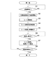
図5はシート給送装置301におけるシート搬送制御手順を示すフローチャートである。この処理プログラムは、ROM701に格納されており、CPU411によって実行される。CPU411は、電源が投入された後、装置エラー、アラーム状況の確認、ファンの風量調整、シート残量などの初期調整制御を行い、これを完了した後、シート給送装置301をスタンバイ状態にする。
FIG. 5 is a flowchart illustrating a sheet conveyance control procedure in the
まず、CPU411は、画像形成装置300内のCPU403から、シート給送装置301内のCPU411にバス405を介して、給紙要求が通知されるまでスタンバイ状態で待機する(ステップS1)。給紙要求が通知されると、画像形成装置300内のCPU403により指定された給紙部から給紙制御を行うべく、CPU411は、ASIC412を介して給紙制御部414に対し、給紙を開始させる(ステップS2)。すなわち、給紙制御部414へファン制御およびモータ搬送制御の制御信号が出力され、収納庫3311、3312のいずれかからシートが1枚ずつ給紙搬送部316a、316bにより分離・搬送される。この後、シートが合流搬送部319の上流部に配置されたシート厚検知装置500に搬送されると、CPU411は、シート厚を検知する(ステップS3)。このシート厚検知処理については後述する。
First, the
CPU411は、シート厚検知装置500によるシート厚の出力値を入力し、シート厚に変換処理した後、バス405を経由して画像形成装置300内のCPU403に通知する(ステップS4)。CPU411は、合流搬送部319の最下流までシート搬送を行い、一旦シートを停止させた時点で、画像形成装置300内のCPU403にシート受渡し準備完了を通知する(ステップS5)。CPU411は、CPU403からの受渡し要求が受渡しタイミング信号440で通知されるまで待機する(ステップS6)。そして、CPU411は、この通知を受け取ると、シートを画像形成装置300に受け渡すとともに、後続のシートを搬送する(ステップS7)。CPU411は、給紙枚数が完了したか否かを判別し(ステップS8)、給紙要求枚数が完了するまで、ステップS2に戻り、同様の処理を繰り返す。給紙枚数が完了すると、CPU411は、シート給送装置301を待機(スタンバイ)状態にして本処理を終了する。
The
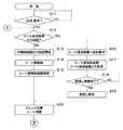
図6および図7は画像形成装置300における画像形成動作手順を示すフローチャートである。この処理プログラムは、画像形成装置300内のROM601に格納されており、CPU403によって実行される。
6 and 7 are flowcharts showing an image forming operation procedure in the
CPU403は、電源が投入された後、装置エラー、アラーム状況の確認、給紙部内のファンの風量制御、シート残量確認、定着プレ温調制御、画像調整制御等の初期調整制御を行い、これを完了した後、画像形成装置300をスタンバイ状態にする。この動作は、シート給送装置301内のCPU411と同様である。
After the power is turned on, the
CPU403は、操作部302、USBあるいはネットワークを介して、ユーザからのJOB要求が発生するまでスタンバイ状態で待機する(ステップS11)。JOB要求が発生すると、ユーザによる手動の設定情報に基づき、コントローラ404からJOB情報が画像形成制御部401に通知される。ここで、JOB情報とは、シート情報、画像情報および排紙処理情報である。なお、本実施形態では、特にシート搬送に関して詳述する。
The
CPU403は、取得したJOB情報に基づき、シート給紙部を決定する。すなわち、CPU403は、画像形成装置300内の本体給紙部313あるいはシート給送装置301内の給紙部311、312を選択し、シート給送装置301から給紙するか否かを判別する(ステップS12)。本体給紙部313が選択された場合、CPU403は、ASIC406を介して、搬送制御部409へのファン制御およびモータ搬送制御の制御信号を出力し、収納庫3313からシートを1枚ずつ給紙搬送部316cにより分離・搬送する(ステップS13)。その後、CPU403は、給紙搬送部316cの下流に配置されたシート厚検知装置501で、搬送されたシートのシート厚を検知する(ステップS14)。このシート厚検知処理については後述する。CPU403は、シート厚検知装置501からシート厚の出力値を入力し、シート厚に変換処理する(ステップS15)。CPU403は、シート厚検知装置501を通過させた後、シートをプレレジセンサ503の位置で一旦停止させ、待機させる(ステップS20)。
The
一方、ステップS12で、JOB情報に基づいて選択されるシート給紙部がシート給送装置301の給紙部311、312である場合、CPU403は、バス405を介してシート給送装置301内のCPU411に給紙要求を通知する(ステップS16)。なお、シート給送装置301内のCPU411による給送制御については、図5において、説明したとおりである。
On the other hand, when the sheet feeding unit selected based on the JOB information is the
CPU403は、CPU411により搬送されるシートのシート厚検知結果を、バス405を介して取得する(ステップS17)。CPU403は、CPU411からの画像形成装置300へのシート受渡し準備完了が通知されるまで待機する(ステップS18)。CPU403は、受渡し準備完了を確認すると同時に、受け渡しタイミング信号440でシート受渡しを要求し、シート給送装置301からシートを受け取る(ステップS19)。そして、ステップS20で、CPU403は、本体給紙部313の場合と同様、プレレジセンサ503の位置(プレレジ位置)でシートを待機させる。
The
シートがプレレジ待機状態にある場合、シート厚検知装置500あるいは501によるシート厚の値が有効であるか否かが判定される。つまり、CPU403は、各給紙部の収納庫に格納されたシート設定情報が有効であるか否かを判断する(ステップS21)。スタンバイ状態で、ユーザによりシート情報が操作部302あるいはホストPCを介して設定されていない場合、CPU403は、シート厚検知装置が無効であると判断し、シート厚検知結果を無視し、ステップS25の処理に進む。
When the sheet is in the pre-registration standby state, it is determined whether the sheet thickness value by the sheet
一方、シート設定情報が有効である場合、CPU403は、シート厚検知装置500あるいは501によるシート厚検知結果と、ユーザにより手動で設定されたシート厚とを比較する(ステップS22)。この場合、シート厚は、ユーザが直接設定できないので、設定可能なシート坪量情報から得られる。すなわち、画像形成装置300内部のROM601、あるいはシート給送装置301内部のROM701内に格納された設定坪量−シート厚変換テーブル(図3参照)を基に、設定されたシート坪量情報は、シート厚み情報に変換される。ステップS22で、シート厚検知装置500、501のシート厚み情報と、ユーザにより設定された坪量情報から得られたシート厚み情報とを比較した結果に応じて、CPU403はつぎのような動作を行う。
On the other hand, when the sheet setting information is valid, the
シート厚検知装置500、501によるシート厚が1枚搬送時のS1L〜S1Hの範囲内に合致した場合、CPU403は、シート厚み情報に相当する温調値を再設定するために、ASIC406を介して定着制御部408に制御値を出力する(ステップS23)。図8は定着温度設定値とシート厚の関係を示すグラフである。定着制御部408に出力される制御値は、図8のグラフから得られるシート厚−定着温調値変換テーブルに基づき、決定される。定着制御部408は、制御値に従ってヒータ制御を行う。
When the sheet thickness detected by the sheet
CPU403は、ヒータの温調(温度調節)が再設定値に対して安定するまで待機する(ステップS24)。なお、スタンバイ状態において、スタンバイ温調温度で制御が行われ、かつJOB要求が発生した時点でシート坪量のユーザ設定が行われている場合、設定坪量の範囲で温調制御は既に行われている。従って、ステップS24でヒータの温調が安定するまでの待機時間は短く、再設定温調値への到達時間は非常に短い時間となる。ただし、メディア(シート媒体)の違いによる定着温調値の再設定の場合、十分に長い安定時間が必要となる。定着温調温度が安定した後、プレレジ位置で待機していたシート搬送を再開するために、CPU403は、ASIC406を介して、搬送制御部409に制御値を出力し、シート搬送再開(プレレジON)を行う(ステップS25)。プレレジON後、CPU403は、画像基準センサ305がONになるのを待つ(ステップS26)。画像基準センサ305のONをトリガとして、CPU403は、作像制御部407に対し、ASIC400、406を介して作像制御を行い、一連の画像形成処理を行う(ステップS27)。一連の画像形成処理は周知技術なので、ここでの説明を省略する。
The
ステップS27の処理後、CPU403は、JOB要求にある所定のシート枚数が終了したか否かを判別する(ステップS28)。所定のシート枚数が終了していない場合、CPU403は、ステップS12の処理に戻る。一方、所定のシート枚数が終了している場合、CPU403は、画像形成装置300をスタンバイ状態(待機状態)とし、本処理を終了する。画像形成装置300から排出された画像形成後のシートは、排紙処理装置304でユーザにより設定されたステイプル、折り、パンチ等の排紙処理が行われた後、排紙トレイ370に排出される。
After the processing in step S27, the
一方、ステップS22で、シート厚検知装置500あるいは501によって検知されたシート厚が1枚搬送時のS1L〜S1Hの範囲内に合致しない場合、CPU403は、つぎのような動作を行う。すなわち、CPU403は、シート厚検知装置からのシート厚み情報と、設定坪量−シート厚変換テーブル(図3参照)内の重送時(2枚搬送時)の値とを比較する(ステップS29)。
On the other hand, if the sheet thickness detected by the sheet
シート厚検知装置500あるいは501によって検知されたシート厚が2枚搬送時の符号S2L〜S2Hに示す範囲内に合致した場合、CPU403は、対象シートが重送していると判断してエスケープ処理を行う(ステップS30)。このエスケープ処理の詳細については後述する。エスケープ処理終了後、CPU403はステップS28の処理に進む。
If the sheet thickness detected by the sheet
一方、ステップS29でシート厚検知装置500あるいは501によって検知されたシート厚が2枚搬送時の符号S2L〜S2Hに示す範囲内に合致しなかった場合、CPU403は、ユーザによる誤設定によるメディア(シート媒体)の違いと判断する。そして、CPU403は、操作部302によってユーザに通知する(ステップS31)。このユーザへの通知画面で、このままJOBを継続するか否かが合わせて通知される。
On the other hand, if the sheet thickness detected by the sheet
CPU403は、JOBの継続が選択されたか否かを判別する(ステップS32)。JOBの継続が選択された場合、CPU403はステップS23の処理に移行する。前述したように、シート厚検知装置500、501によるシート厚の検知結果に基づく制御に変更するために、定着温調値が再設定され、JOBが継続される。また、この場合、ユーザにより設定されたメディア(シート媒体)に基づく厚さと検出した厚さとの差異が大きい(シート厚み差が大きい)場合、温調安定時間は通常時よりも長い時間必要となる。
The
一方、ステップS32でJOBの継続がユーザにより拒否された場合、CPU403は、JOB自体を中止処理とする(ステップS33)。そして、CPU403は、JOBの中止に伴い、画像形成装置300とシート給送装置301の搬送部における残留シートを強制排出するためにエスケープ処理を行う(ステップS34)。このエスケープ処理により、残留シートが全て排出された後、CPU403は、画像形成装置300をスタンバイ(待機)状態とし、本処理を終了する。
On the other hand, when the continuation of the job is rejected by the user in step S32, the
図9はステップS30、S34におけるエスケープ処理手順を示すフローチャートである。CPU403は、エスケープ処理が必要であると判断した時点、つまりステップS30、S34においてこの処理を開始する。まず、CPU403は、エスケープ排紙トレイ101が満載であるか否かをエスケープ満載検知センサ102のステータスで判断する(ステップS51)。
FIG. 9 is a flowchart showing an escape processing procedure in steps S30 and S34. The
エスケープ排紙トレイ101が非満載である場合、CPU403は、エスケープ搬送を許可し、ステップS54の処理に遷移する。一方、エスケープ排紙トレイ101が満載である場合、シート給送装置301内のCPU411は、バス405を介して画像形成装置300内のCPU403にその旨を通知する。
If the escape
CPU403は、操作部302でエスケープ排紙トレイ101のシート排除を行うように、ユーザに通知する(ステップS52)。CPU403は、ユーザによりシートが排除されるまで待機する(ステップS53)。ステップS53でシート排除後にエスケープ搬送が許可された場合、CPU403は、搬送制御部409によりフラッパ310を駆動し、エスケープ排紙トレイ101の搬送方向に回動させる(ステップS54)。なお、ステップS51でエスケープ排紙トレイ101が非満載である場合も同様である。
The
CPU403は、搬送制御部409の制御信号により、エスケープ排紙トレイ101への搬送パス上に設けられた搬送モータ(図示せず)を駆動する(ステップS55)。CPU403は、搬送モータ(図示せず)の駆動により、シートが待機しているプレレジセンサ503の位置からシート搬送再開(プレレジON)を行う(ステップS56)。これにより、フラッパ310を介してエスケープ排紙トレイ101に向けてシートが搬送され、排出される。エスケープ排紙トレイ101直前の排出口には、エスケープ排紙センサ(図示せず)が設けられている。CPU403は、このセンサ出力を、搬送制御部409を介して検知することより、シートの排出を確認し、シートが排出されるまで待つ(ステップS57)。シートが排出されると、CPU403は、元の処理に復帰する。
The
図10はシート厚検知装置の機械的構成を示す図である。シート厚検知装置500、501は、パスの構成を除き、基本的に同一の構成を有する。従って、ここでは、シート厚検知装置500についてだけ説明する。
FIG. 10 is a diagram illustrating a mechanical configuration of the sheet thickness detection apparatus. The sheet
合流搬送パス910は、対向する板金で形成され、図中矢印C方向にシート909が搬送されるように構成されている。搬送ローラ対907は、シート厚検知装置500の上流側に位置し、上流搬送モータ916により駆動される。搬送ローラ対911は、シート厚検知装置500の下流側に位置する下流搬送モータ917により駆動される。搬送ローラ対907、911は、シート909を搬送する。また、搬送センサ914は、反射型の光学センサであり、合流搬送パス910中のシート909の位置検出を行うように配置されている。
The merging / conveying
シート厚検知装置500は、つぎのような構成を有する。固定ローラ918は、合流搬送パス910にそのローラ軸が固定した状態で配置されている。固定ローラ918に対し、検知ローラ906によりニップ圧力が図中A方向にかけられている。固定ローラ918および検知ローラ906は、シートが間に搬送されるように接触する従動ローラである。
The sheet
検知ローラ906は、そのローラ軸が揺動部材919の一端に接続され、シート909の搬送力により図中矢印k方向に回転する。揺動部材919は、その一端部である検知ローラ906がシート909に当接し、その厚み方向に揺動することで、回動軸(支点)903を中心に図中B方向に回動自在である。また、揺動部材919は、シート909の搬送方向Cに対し、シート909を搬送していない初期状態で、45°の角度となるように配置されている。揺動部材919の他端には、磁性体902が配置されている。磁性体902と対向する位置には、揺動部材919と略平行に一定間隔を置いて、磁気センサ901が配置されている。本実施形態では、磁気センサとしてホール素子が使用される。そして、上記一定間隔は1.0mmに設定されている。また、揺動部材919の他端には、弾性部材904が接続されている。弾性部材904は、揺動部材919をシート909の搬送方向Cに引っ張っている。弾性部材904の他端には、同方向の延長線上の圧切替ソレノイド905(圧力変更手段)が接続されている。
The roller shaft of the
図11は弾性部材904の張力と圧切替ソレノイド905の動作量の関係を示す図である。非駆動状態において、圧切替ソレノイド905は、長さX1の位置に延伸されている。このとき、張力F1は、バネ係数をKとして、数式(1)で表される。
FIG. 11 is a diagram showing the relationship between the tension of the
F1=KX1 …… (1)
一方、駆動状態において、圧切替ソレノイド905は、長さX2の位置に延伸されている。このとき、張力F2は、数式(2)で表される。
F1 = KX1 (1)
On the other hand, in the driving state, the
F2=KX2 …… (2)
本実施形態では、張力F2が張力F1の4倍の張力となるように、長さX1、X2は数式(3)に示すように設定されている。
F2 = KX2 (2)
In the present embodiment, the lengths X1 and X2 are set as shown in Equation (3) so that the tension F2 is four times the tension F1.
X1×4=X2 …… (3)
このような構成を有するシート厚検知装置500では、シート909の厚み量に応じて検知ローラ906が揺動し、その揺動量が揺動部材919の他端に伝達され、揺動部材919は回動する。この回動により、磁気センサ901と磁性体902との距離が増加する。これにより、磁気センサ901によって検知される磁性体902の磁束量は、その距離の増加に反比例して減少する。また、この磁束量の変化は、磁気センサ901により電圧として出力される。磁気センサ901の出力変化量を検出することで、シート909の厚み量が検知される。なお、磁気センサ901および磁性体902は変位量検知手段の一例である。
X1 × 4 = X2 (3)
In the sheet
図12はシート厚検知装置の電気的構成を示すブロック図である。シート厚検知装置500、501は略同一の電気的構成を有するので、ここでは、シート給送装置301についてだけ説明する。
FIG. 12 is a block diagram showing an electrical configuration of the sheet thickness detection apparatus. Since the sheet
上流搬送モータ916は、搬送パスに設けられ、搬送制御部415内に設けられた駆動回路922により駆動される。駆動回路922には、ASIC412を介してCPU411から制御信号が入力される。下流搬送モータ917も、同様に駆動回路922により駆動される。圧切替ソレノイド905も、同様に、搬送制御部415内の駆動回路908により駆動される。駆動回路908には、ASIC412を介してCPU411から制御信号が入力される。圧切替ソレノイド905は、駆動時に吸引され、非駆動時に開放される。搬送センサ914の信号はASIC412に入力され、CPU411によりそのステータスが監視(モニタ)される。
The
シート厚検知センサである磁気センサ901は、センサ駆動回路912により定電流で駆動される。磁気センサ901のセンサ出力値は、微小であるので、出力増幅回路920で増幅された後、SN比を改善するためのLPF921を介して、CPU411のAD変換部に入力される。
A
図13はシート厚検知装置500における圧切替制御手順を示すフローチャートである。この制御プログラムは、ROM701に格納されており、CPU411によって実行される。この圧切替制御は、画像形成システムにおける電源ON後の初期調整制御の一部である。また、この制御は、シート給送装置301の初期調整制御における任意のタイミングを開始点として実行される。なお、画像形成装置300内のシート厚検知装置501においても同様に行われる。
FIG. 13 is a flowchart showing a pressure switching control procedure in the sheet
シート厚検知装置500において、CPU411は、シート909の非通紙時、磁気センサ901の出力値をAD変換部でサンプリングを行う(ステップS61)。このときのサンプリング周期は4msである。また、サンプリングは5ポイントで行われる。
In the sheet
CPU411は、取得した5ポイントのサンプリング値のうち、最大値および最小値のデータを廃棄し、残った3ポイントのサンプリング値の平均値を算出する(ステップS62)。CPU411は、この平均化後のセンサ出力値をセンサ初期値として取得し(ステップS65)、RAM702の所定アドレス域に格納する(ステップS64)。これ以降、シート給送装置301の初期調整制御が実行されると、センサ初期値は更新されるが、それまで以前のセンサ初期値が使用される。
The
CPU411は、給紙部311、312に格納されているシート情報(サイズ、坪量、表面性)がユーザにより操作部302あるいは外部ホストPCを介して設定されたか否かを判別する(ステップS65)。ユーザによりシート情報が設定されていない場合、CPU411は、ステップS68の処理に進む。一方、ユーザによりシート情報が設定された場合、CPU411は、シート坪量が52g/m2より大きいか否かを判別する(ステップS66)。シート坪量が52g/m2より大きい場合、CPU411は、検知ローラ906と固定ローラ918とのニップ圧が「強」となるように、圧切替ソレノイド905をONに設定し、給紙部ごとにRAM702の所定アドレス域に記憶する(ステップS67)。この後、CPU411は本処理を終了する。一方、ステップS66で52g/m2以下の場合、CPU411は、ニップ圧が「弱」となるように、圧切替ソレノイド905をOFFに設定し、給紙部ごとにRAM702の所定アドレス域に記憶する(ステップS68)。この後、CPU411は本処理を終了する。一方、ステップS65でシート情報がユーザにより設定されていない場合、CPU411は、ステップS68で各給紙部ごとに強制的にニップ圧が「弱」となるように、圧切替ソレノイド905をOFFに設定する。そして、CPU411は、シート情報の設定なしをRAM702の所定アドレス領域に記憶し、本処理を終了する。なお、ステップS66〜S68の処理は圧力変更手段に対応する。
The
図14はステップS3、S14におけるシート厚検知装置におけるシート厚検知手順を示すフローチャートである。このシート厚検知処理は、前述した図5、図6および図7におけるシート給送装置および画像形成装置における制御処理の一部である。 FIG. 14 is a flowchart showing a sheet thickness detection procedure in the sheet thickness detection apparatus in steps S3 and S14. This sheet thickness detection process is a part of the control process in the sheet feeding apparatus and the image forming apparatus in FIGS. 5, 6, and 7 described above.
CPU411は、RAM702を参照し、前述した図13の圧切替制御処理で決定されたニップ圧となるように、圧切替ソレノイド905のON/OFFを制御する(ステップS71)。このとき、ASIC412から駆動回路908に出力されるON時の制御信号は、PWM信号である。これにより、連続して圧切替ソレノイド905をONにすることによる温度上昇は防止される。
The
CPU411は、シート厚検知装置500の直上流に配置された搬送センサ914の出力を、ASIC412を介して監視し、搬送センサ914がONになるまで待つ(ステップS72)。搬送センサ914がONになって、シート909の通過が検知されると、CPU411は、所定時間待機する(ステップS73)。つまり、シート909の検知ローラ906への突入時のショックによる揺動部材の振動が安定するまで、CPU411は、磁気センサ901のセンサ出力値をセンサ値として採用しないように制御する。
The
図15はシート厚検知装置500の出力波形の時間変化を示すグラフである。本実施形態では、図15に示すように、シート検知開始から検知ローラへの突入時のショックによる非安定時間Tは、最大で120msである。従って、CPU411は、非安定時間T以上の所定時間経過後、シート909の通紙時における磁気センサ901の出力値に対し、AD変換部でサンプリングを行う(ステップS74)。このときのサンプリング周期は4msである。サンプリングは5ポイントで行われる。
FIG. 15 is a graph showing the time change of the output waveform of the sheet
CPU411は、ステップS74で取得したサンプリング値に対し、最大値および最小値のデータを廃棄し、残った3ポイントの平均値を算出する(ステップS75)。CPU411は、この平均化後のセンサ出力平均値をシート厚検知センサの出力値とする。
The
CPU411は、ROM701に格納されたシート厚検知装置のシート厚出力−シート厚変換テーブル(図4参照)を参照し、このテーブルに基づき、シート厚検知センサの出力値をシート厚み情報に変換する(ステップS76)。そして、CPU411は、この変換されたシート厚み情報をシート厚の値に決定し、RAM702の給紙部ごとに設けられた所定アドレス領域に記憶する(ステップS77)。
The
第1の実施形態のシート厚検知装置500は、シート厚に追従して揺動する揺動部材919の変位量を、揺動部材919に配置された磁性体902とこれに対向する面に配置されたホール素子を用いた磁気センサ901により検出する構成を有する。揺動部材919のシート厚に追従した揺動量の検知方法としては、このような構成に限られるものではない。例えば、光学センサを用いて揺動部材919の変位量を検知することでも、同様に制御することが可能である。図16は光学センサ1500を用いた場合のシート厚検知装置の機械的構成を示す図である。揺動部材919の他端部には、揺動方向と平行にスリット板(図示せず)が配置されている。また、光学センサ1500は、スリット板のスリットを検知可能に配置され、このスリットを検知することにより揺動部材919の変位量を検知する。
In the sheet
また、揺動部材919に対して磁性体(マグネット)902と磁気センサ901の配置関係を変更し、揺動部材919の変位量を検知するようにしてもよい。図17は揺動部材919に対して磁性体902と磁気センサ901の配置関係を変更した場合のシート厚検知装置の機械的構成を示す図である。揺動部材919の端面に磁性体902が設けられている。また、磁性体902と対向して磁気センサ901が配置されている。このような配置関係により、揺動部材919の揺動量(変位量)は検知可能である。また、前述した圧切替ソレノイド905を併用することで、略同様の効果が得られる。
In addition, the positional relationship between the magnetic body (magnet) 902 and the
また、揺動部材919の揺動時の回動角度を変位角として検知することでも、シート厚に相当する揺動部材919の変位量を検知することが可能である。図18は揺動部材919の揺動時の回動角度を検知する場合のシート厚検知装置の機械的構成を示す図である。具体的に、揺動部材919の回動軸に円柱状に成型された磁性体1700が配置される。磁性体1700には、N極、S極が各々半円分着磁されている。この磁極の変化点に対向する面には、磁気センサ1701が配置され、軸の変位角(回動角度)を検知する。
Further, the amount of displacement of the
また、光学エンコーダを用いて軸の変位角を検知することでも、揺動部材919の変位量を検知することが可能である。図19は光学エンコーダを用いて軸の変位角を検知する場合のシート厚検知装置の機械的構成を示す図である。回動軸903に、放射状のスリットを有した円盤スリット1801(円形スリット板)を配置し、そのスリットの有無を光学センサ1800によって検知するように構成された光学エンコーダを用いることで、軸の変位角(回転量)を検知することが可能である。
Further, it is also possible to detect the displacement amount of the
また、その変位角量から揺動部材919のシート厚に相当する揺動量を検知することで、シート厚みを検知することが可能である。また、圧切替ソレノイド905を併用することで、略同様の効果が得られる。
Further, the sheet thickness can be detected by detecting a swing amount corresponding to the sheet thickness of the
第1の実施形態のシート厚検知装置によれば、シート情報に基づき、シート厚が大きいほどシートへの圧力を低くするように、従動部材のシートへの圧力を変更する。これにより、シート折れ、皺などによってシートの品位を損なうことが無くなる。また、シート厚を検知するセンサの出力が安定するまでの時間を短縮することができ、シート厚検知を行う時間を確保することが可能となる。従って、多くの種類に亘るシートのシート厚を精度良く検出することができる。 According to the sheet thickness detection apparatus of the first embodiment, based on the sheet information, the pressure on the sheet of the driven member is changed so that the pressure on the sheet decreases as the sheet thickness increases. As a result, there is no loss of sheet quality due to sheet breakage, wrinkles, and the like. Further, the time until the output of the sensor for detecting the sheet thickness is stabilized can be shortened, and the time for detecting the sheet thickness can be secured. Therefore, it is possible to accurately detect the sheet thickness of many types of sheets.
また、シートの坪量(厚み)の他、シートのサイズや表面性をもとに、シートへの圧力を制御することも可能である。また、ユーザ設定から、シート情報を容易に得ることができる。また、揺動部材の揺動量を変位量として検知するので、シート厚を簡単に変位量として捉えることができる。また、揺動部材の一端部が検知ローラであるので、シートへの突入時のショックを低減することができる。また、複数の搬送ローラ対でシートを搬送するので、シートの搬送が容易である。また、検知ローラが固定ローラと接触するので、シートへの突入時のショックを低減することができる。 In addition to the basis weight (thickness) of the sheet, it is also possible to control the pressure on the sheet based on the size and surface properties of the sheet. Also, sheet information can be easily obtained from user settings. Further, since the swing amount of the swing member is detected as the displacement amount, the sheet thickness can be easily grasped as the displacement amount. In addition, since one end of the swing member is a detection roller, it is possible to reduce a shock at the time of entering the sheet. Further, since the sheet is conveyed by a plurality of conveyance roller pairs, the sheet can be easily conveyed. Further, since the detection roller comes into contact with the fixed roller, it is possible to reduce a shock at the time of entering the sheet.
また、圧切替ソレノイドにより、弾性部材の張力を切り替えることで、シートへの圧力を容易に変更することができる。また、磁気的検知、光学的検知、あるいは軸の変位角検知など、種々の方法で揺動部材の変位量を検知することができる。 Further, the pressure on the seat can be easily changed by switching the tension of the elastic member by the pressure switching solenoid. Further, the displacement amount of the swinging member can be detected by various methods such as magnetic detection, optical detection, or shaft displacement angle detection.
また、画像形成装置から出力されるシートの成果物の品位が向上する。また、画像プロセス制御を適切に行うことができる。また、シート給送装置から出力されるシートの成果物の品位が向上する。 Further, the quality of the product of the sheet output from the image forming apparatus is improved. In addition, image process control can be performed appropriately. Further, the quality of the product of the sheet output from the sheet feeding apparatus is improved.
[第2の実施形態]
第2の実施形態では、ユーザが操作部302およびホストPC(図示せず)からシート情報を設定する際、特に、シート厚検知装置500、501で用いられるシート坪量の設定に人為的誤りが発生した場合について説明する。なお、第2の実施形態の画像形成システムの構成は、前記第1の実施形態と同様であるので、その説明を省略する。
[Second Embodiment]
In the second embodiment, when the user sets the sheet information from the
図20は第2の実施形態のシート厚検知装置を有するシート給送装置における給紙部のシートステータス更新手順を示すフローチャートである。この処理プログラムは、シート給送装置301内のROM701に格納されており、スタンバイ動作中の任意の開始時点でCPU411によって実行される。なお、ここでは、シート給送装置301を代表例として示すが、画像形成装置300であっても同様である。
FIG. 20 is a flowchart illustrating a sheet status update procedure of the sheet feeding unit in the sheet feeding apparatus having the sheet thickness detection apparatus according to the second embodiment. This processing program is stored in the
シート給送装置301がスタンバイ(待機)状態において、CPU411は、JOB発生時の初期制御として、本処理を実行する。まず、CPU411は、JOB発生時の対象となる給紙部に対し、前回JOB発生後のスタンバイ中において、対象となる給紙部の収納庫の開閉動作がユーザにより行われた履歴があるか否かを確認する(ステップS81)。
When the
収納庫の開閉動作が行われなかった場合、CPU411は、給紙部の収納庫内に格納されたシートが前回のJOB実行時から変更されていないと判断する。そして、CPU411は、前回JOB時に計測したシート厚の値を優先して採用するように、前回のシート厚の値を有効とし、RAM702内の所定アドレス域に対象となる給紙部を記憶する(ステップS87)。この後、CPU411は本処理を終了する。
In the case where the opening / closing operation of the storage is not performed, the
一方、対象となる給紙部に対し、収納庫の開閉動作が行われた履歴がある場合、CPU411は、シート補給時に収納庫内のシート残りが存在していたか否かを判定する(ステップS82)。シート残りが存在しなかった場合、つまりシート無し状態であった場合、CPU411は、シートの補給を判別するため、ステップS84の処理に進む。
On the other hand, when there is a history of opening / closing operation of the storage for the target paper feed unit, the
一方、ステップS82でシート残りが存在した場合、CPU411は、シート残り分を収納庫からユーザが除去したか否かを確認する(ステップS83)。残りシートを除去した場合、収納庫内はシート無し状態となるので、CPU411は、シートが補給されたか否かを確認する(ステップS84)。シートが補給されないまま収納庫が閉じられた場合、CPU411は、対象となる給紙部の収納庫内はシート無し状態であると判断し、待機状態に移行して本処理を終了する。
On the other hand, if there is a remaining sheet in step S82, the
一方、ステップS84でシートの補給が行われた場合、補給操作後、ユーザは操作部302からシート情報を設定する必要がある。このとき、従来と同じシートである場合、シート情報の設定を行う必要はないが、従来と異なる種類のシートが補給された場合、シート情報の設定を更新する操作を行う必要がある。しかし、この場合、任意のユーザ操作が介入するので、人為的誤操作が発生するおそれがある。
On the other hand, when the sheet is replenished in step S84, the user needs to set sheet information from the
シートの補給が行われた場合、CPU411は、対象となる給紙部に対し、検知ローラ906のシートへのニップ圧が弱くなるように、強制的に圧切替ソレノイドをOFFにするステータス(シート厚値ステータス)をRAM702に記憶する(ステップS86)。これは、誤操作により設定されたシートの種類と実際の種類とが異なる場合においても、ニップ圧が強いことによる紙詰まり等の搬送不良を発生させないためである。この後、CPU411は、待機状態に移行して本処理を終了する。
When the sheet is replenished, the
一方、ステップS83でシート残りを除去しなかった場合、CPU411は、ユーザによるシートの補給が行われたか否かを確認する(ステップS85)。シートの補給が行われた場合、ユーザにより残りシートと同じ種類のシートが追加・補給されたと考えられる。しかし、前述したように、人為的誤操作の可能性がある。そこで、CPU411は、対象となる給紙部に対し、検知ローラ906のシートに対するニップ圧が弱くなるように、ステップS86で、強制的に圧切替ソレノイドをOFFにするステータス(シート厚値ステータス)をRAM702に記憶する。
On the other hand, if the remaining sheet is not removed in step S83, the
一方、シートの補給が行われず、収納庫が閉じられた場合、CPU411は、前回JOB時に計測されたシート厚から変更されていないと判断する。そして、CPU411は、ステップS87で、前回JOB時に計測されたシート厚の値を優先して採用するように、前回シート厚の値を有効としてRAM702の所定アドレス域に対象となる給紙部を記憶する。この後、CPU411は待機状態に移行して本処理を終了する。なお、ステップS84、S85の処理はシート入換操作が行われたか否かを判別する処理に相当する。
On the other hand, when the sheet is not replenished and the storage is closed, the
図21はシート厚検知処理手順を示すフローチャートである。前記第1の実施形態の図14に示すステップ処理と同一のステップ処理についてその説明を省略する。具体的に、ステップS94〜S100の処理は、図14のステップS71〜S77の処理と同じである。 FIG. 21 is a flowchart showing a sheet thickness detection processing procedure. The description of the same step process as that shown in FIG. 14 of the first embodiment is omitted. Specifically, the processing in steps S94 to S100 is the same as the processing in steps S71 to S77 in FIG.
CPU411は、シート厚検知処理を開始すると、図20で説明したシート厚ステータスを確認し、強制的に圧切替ソレノイドをOFFにする設定(ソレノイド強制OFF)となっているか否かを確認する(ステップS91)。ソレノイド強制OFFではなく、前回のシート厚の値が有効となっている場合、CPU411は、ステップS94において、前回シート厚の値と同一の制御により圧切替ソレノイドを駆動する。
When the
一方、ステップS91でソレノイド強制OFFのステータスである場合、CPU411は、シート情報の誤設定の可能性があるので、シート厚検知用の搬送制御に移行する(ステップS92)。ここで、シート厚検知用の搬送制御において、シート給送装置301は、給紙搬送部316a、316bの搬送速度に対し、上部搬送部317、下部搬送部318を介して減速制御を行う。そして、合流搬送部319に設けられたシート厚検知装置500は、画像形成時の規定の搬送速度よりも十分遅い速度でシート厚検知を行う。このように、シート入換操作が行われたと判別された場合、1枚目に搬送されるシートに対し、シートに対するニップ圧が弱くなるように圧力を付与するとともに、搬送速度を遅くする。
On the other hand, if the status is the solenoid forced OFF status in step S91, the
一方、画像形成装置300では、給紙搬送部316cからシート厚検知装置501までの搬送路が短いので、減速制御は困難である。このため、画像形成装置300は、シート厚検知装置501内の搬送センサ914をシートが通過した後、所定時間が経過した時点でシート搬送を停止させ、その後、シートの再搬送を開始させる。この停止期間中、シート厚検知装置501は、シート厚検知を行う。
On the other hand, in the
これにより、通常制御におけるシート搬送速度より十分に搬送速度が低下した状態、もしくは停止した状態で、シート厚検知が行われる。従って、ソレノイド強制OFFにより、検知ローラ906によるシートへのニップ圧が低下した状態においても、検知ローラ906へのシート突入時のショックによるセンサ誤検知を発生させず、高精度にシート厚が検知可能となる。また、ユーザ誤操作により、シート情報と異なったシートが通紙された場合においても、搬送不良が生じず、シート厚検知に影響が及ばない。
Thereby, sheet thickness detection is performed in a state where the conveyance speed is sufficiently lower than the sheet conveyance speed in the normal control or in a stopped state. Therefore, even when the nip pressure on the sheet by the
CPU411は、ステップS92でシート厚検知用の搬送制御を行った後、シート厚ステータスであるソレノイド強制OFFを解除する(ステップS93)。この後、CPU411はステップS95の処理に進む。
In step S92, the
前述したように、ステップS95からステップS100までの処理は、前記第1の実施形態の図14に示したステップ処理と同様である。但し、2枚目以降に搬送されるシートに対しては、ステップS100で決定されたシート厚の値に基づき、圧切替ソレノイドが駆動されるようになる。つまり、再度、この処理を行う際、前回と同一の給紙部を駆動する場合、シート厚ステータスが解除(クリア)されている。このため、ステップS92、S93の処理は行われず、収納庫内のシート厚に適したニップ圧となるように、圧切替ソレノイドが駆動される。 As described above, the processing from step S95 to step S100 is the same as the step processing shown in FIG. 14 of the first embodiment. However, for the second and subsequent sheets, the pressure switching solenoid is driven based on the sheet thickness value determined in step S100. That is, when this process is performed again, the sheet thickness status is canceled (cleared) when the same paper feeding unit as that of the previous time is driven. For this reason, the processing of steps S92 and S93 is not performed, and the pressure switching solenoid is driven so that the nip pressure is suitable for the sheet thickness in the storage.
第2の実施形態のシート厚検知装置によれば、検出したシート厚に基づき、シート厚が大きいほどシートへの圧力を低くするように、従動部材のシートへの圧力を変更する。従って、前記第1の実施形態と同様、多くの種類に亘るシートのシート厚を精度良く検出することができる。 According to the sheet thickness detection apparatus of the second embodiment, based on the detected sheet thickness, the pressure on the sheet of the driven member is changed so that the pressure on the sheet decreases as the sheet thickness increases. Therefore, as in the first embodiment, it is possible to accurately detect the sheet thickness of many types of sheets.
また、各給紙部内のシート情報を設定する際、ユーザの誤操作が発生しても、各給紙部内に設置されたシート厚ステータスを監視し、そのステータスに応じて、誤操作が疑われるシートのみシート厚検知を行う。これにより、ユーザによりシート種類の設定が誤って行われた場合であっても、シート厚を正確に検出することができる。従って、誤操作により設定されたシートと異なる種類のシートが通紙された場合においても、揺動部材のシートへの圧力が強いことによるシート詰まり等の搬送不良を発生させないようにすることができ、成果物であるシートの品位を落とすことが無い。 In addition, when setting the sheet information in each paper feed unit, even if a user's erroneous operation occurs, the sheet thickness status installed in each paper feed unit is monitored, and only the sheets that are suspected of being erroneously operated according to the status. Sheet thickness detection is performed. As a result, even when the user sets the sheet type by mistake, the sheet thickness can be accurately detected. Therefore, even when a sheet of a different type from the sheet set by an erroneous operation is passed, it is possible to prevent a conveyance failure such as a sheet jam due to a strong pressure on the sheet of the swing member, There is no loss of quality of the deliverable sheet.
また、シート情報を設定する際、ユーザの誤操作が発生しても、誤操作が疑われるシートのみシート厚の検出を行うことができる。これにより、シート折れ、皺などのシートの品位を損なうことなく、シート厚情報から、重送シートの混入を防止することができ、また、画像プロセス制御を適切に行うことが可能となる。従って、画像形成装置やシート給送装置から出力されるシートの成果物の品位が向上する。 Further, when setting sheet information, even if a user's erroneous operation occurs, only the sheet suspected of erroneous operation can be detected. Accordingly, it is possible to prevent mixing of the multi-feed sheets from the sheet thickness information without damaging the sheet quality such as sheet folding and wrinkles, and to appropriately perform image process control. Therefore, the quality of the sheet product output from the image forming apparatus or the sheet feeding apparatus is improved.
また、1枚目のシートの搬送速度を遅くもしくは停止にするので、揺動部材のシートへの圧力が低くなった状態において、揺動部材へのシート突入時のショックによる誤検知を発生させず、高精度にシート厚が検出可能となる。また、ユーザの誤操作により、シート情報と異なったシートが通紙された場合においても、搬送不良が生じず、シート厚の検出に影響が及ばない。 In addition, since the conveyance speed of the first sheet is slowed or stopped, erroneous detection due to a shock when the sheet enters the swinging member does not occur when the pressure of the swinging member on the sheet is low. The sheet thickness can be detected with high accuracy. Further, even when a sheet different from the sheet information is passed due to an erroneous operation by the user, no conveyance failure occurs and the detection of the sheet thickness is not affected.
なお、上記実施の形態では、画像形成装置、あるいはシートを画像形成装置に供給するシート給送装置に本発明を適用する例を示したが、本発明はこれに限定されるものではない。例えば、後処理装置に画像形成済みのシートを供給するシート供給装置や、画像形成装置と後処理装置との間に配置され、画像形成装置で画像が形成されて搬送されてくるシートの間に他のシートを供給するインサータ等の装置に本発明を適用してもよい。 In the above-described embodiment, an example in which the present invention is applied to an image forming apparatus or a sheet feeding apparatus that supplies a sheet to the image forming apparatus has been described, but the present invention is not limited to this. For example, a sheet supply device that supplies an image-formed sheet to the post-processing device, or a sheet that is disposed between the image forming device and the post-processing device, and on which the image is formed and conveyed by the image forming device. The present invention may be applied to an apparatus such as an inserter that supplies other sheets.
また、上記実施形態では、従動部材として、シート厚の変位量を回動量(揺動量)として検知可能な揺動部材を用いた場合を示したが、シートの厚み方向に移動して変位量を検知可能な移動部材を用いてもよい。 In the above-described embodiment, the case where the swing member that can detect the displacement amount of the sheet thickness as the rotation amount (swing amount) is used as the driven member. However, the displacement amount is determined by moving in the sheet thickness direction. A detectable moving member may be used.
また、上記実施形態では、シート情報はユーザにより設定されたが、装置自体がシート特性を検知することにより、シート情報を取得するようにしてもよく、シート特性の検知から容易にシート情報を取得することができる。 In the above embodiment, the sheet information is set by the user. However, the apparatus itself may acquire the sheet information by detecting the sheet characteristics. The sheet information can be easily acquired from the detection of the sheet characteristics. can do.
また、上記実施形態では、シート厚に応じてシートへの圧力を2段階に切り替える場合を示したが、シート厚に応じてシートへの圧力を3段階以上に切り替えてもよいし、また、シート厚に応じて連続的にシートへの圧力を変更するようにしてもよい。 In the above embodiment, the case where the pressure on the sheet is switched in two stages according to the sheet thickness is shown. However, the pressure on the sheet may be switched in three stages or more depending on the sheet thickness. You may make it change the pressure to a sheet | seat continuously according to thickness.
また、上記実施形態では、シート入換操作が行われたことの判別として、収納庫の開閉やシートの補給を判別したが、その他、シートの設置、交換、除去、残量などを判別するようにしてもよい。これにより、収納部の開閉やシートの補給など、シート情報が誤って設定されるおそれのある状況を容易に想定することができる。 Further, in the above embodiment, as the determination that the sheet replacement operation has been performed, the opening / closing of the storage and the replenishment of the sheet are determined, but in addition, the installation, replacement, removal, remaining amount, etc. of the sheet are determined. It may be. Accordingly, it is possible to easily assume a situation where the sheet information may be erroneously set, such as opening / closing of the storage unit or sheet supply.
300 画像形成装置
301 シート給送装置
302 操作部
311、312、313 給紙部
500、501 シート厚検知装置
905 圧切替ソレノイド
909 シート
919 揺動部材
DESCRIPTION OF
Claims (8)
前記シートの坪量に関するシート情報を取得する取得手段と、
搬送路に沿って前記シートを搬送する搬送手段と、
搬送される前記シートに当接するように前記搬送路に設けられ、前記シートの厚さに追従して変位する従動部材と、
前記従動部材が前記シートへ与える圧力を変更する圧力変更手段と、
前記従動部材の変位量を検知する変位量検知手段と、
前記変位量検知手段による検知結果に基づき、前記シートの厚さを検出する検出手段と、
前記検出手段によりシートの厚さを検出する場合に、前記取得手段により取得されたシート情報に基づく前記シートの坪量が第1の坪量のときの前記従動部材が前記シートへ与える圧力を、前記シートの坪量が前記第1の坪量よりも大きい第2の坪量のときの前記従動部材が前記シートへ与える圧力よりも低くするように、前記圧力変更手段を制御する制御手段と、
を備えたことを特徴とするシート厚検出装置。 In the sheet thickness detection device that detects the thickness of the conveyed sheet,
Obtaining means for obtaining sheet information on the basis weight of the sheet;
Conveying means for conveying the sheet along a conveying path;
A driven member that is provided in the conveyance path so as to abut on the conveyed sheet and is displaced following the thickness of the sheet;
Pressure changing means for changing the pressure applied to the seat by the driven member;
A displacement amount detecting means for detecting a displacement amount of the driven member;
Detection means for detecting the thickness of the sheet based on a detection result by the displacement amount detection means;
When the thickness of the sheet is detected by the detection unit, the pressure applied to the sheet by the driven member when the basis weight of the sheet based on the sheet information acquired by the acquisition unit is a first basis weight , Control means for controlling the pressure changing means so as to make the driven member lower than the pressure applied to the sheet when the basis weight of the sheet is a second basis weight larger than the first basis weight;
A sheet thickness detection apparatus comprising:
Priority Applications (2)
| Application Number | Priority Date | Filing Date | Title |
|---|---|---|---|
| JP2010042450A JP5546288B2 (en) | 2010-02-26 | 2010-02-26 | Sheet thickness detection apparatus, image forming apparatus, and sheet feeding apparatus |
| US13/034,102 US8328192B2 (en) | 2010-02-26 | 2011-02-24 | Sheet thickness detection device and image forming apparatus |
Applications Claiming Priority (1)
| Application Number | Priority Date | Filing Date | Title |
|---|---|---|---|
| JP2010042450A JP5546288B2 (en) | 2010-02-26 | 2010-02-26 | Sheet thickness detection apparatus, image forming apparatus, and sheet feeding apparatus |
Publications (3)
| Publication Number | Publication Date |
|---|---|
| JP2011178488A JP2011178488A (en) | 2011-09-15 |
| JP2011178488A5 JP2011178488A5 (en) | 2013-09-12 |
| JP5546288B2 true JP5546288B2 (en) | 2014-07-09 |
Family
ID=44504882
Family Applications (1)
| Application Number | Title | Priority Date | Filing Date |
|---|---|---|---|
| JP2010042450A Expired - Fee Related JP5546288B2 (en) | 2010-02-26 | 2010-02-26 | Sheet thickness detection apparatus, image forming apparatus, and sheet feeding apparatus |
Country Status (2)
| Country | Link |
|---|---|
| US (1) | US8328192B2 (en) |
| JP (1) | JP5546288B2 (en) |
Families Citing this family (25)
| Publication number | Priority date | Publication date | Assignee | Title |
|---|---|---|---|---|
| JP5323631B2 (en) * | 2009-09-29 | 2013-10-23 | 大日本スクリーン製造株式会社 | Inkjet image recording apparatus and belt conveyance correction method |
| JP2013159458A (en) * | 2012-02-07 | 2013-08-19 | Ricoh Co Ltd | Paper thickness detecting device, carrying device and image forming device |
| JP5988289B2 (en) * | 2012-04-27 | 2016-09-07 | 株式会社小森コーポレーション | Sheet overlap feed detection device |
| JP6202357B2 (en) * | 2012-07-11 | 2017-09-27 | 株式会社リコー | Sheet material thickness detection apparatus and image forming apparatus using the same |
| JP6020086B2 (en) * | 2012-11-21 | 2016-11-02 | 株式会社リコー | Thickness measuring device |
| JP6070144B2 (en) * | 2012-12-13 | 2017-02-01 | 株式会社リコー | Recording medium thickness detection apparatus, image forming apparatus, recording medium thickness detection method, and program |
| JP6286822B2 (en) * | 2012-12-25 | 2018-03-07 | 株式会社リコー | Multifeed determination device, image forming apparatus, multifeed determination method, and multifeed determination method program |
| JP6079229B2 (en) * | 2012-12-28 | 2017-02-15 | 株式会社リコー | Sheet conveying apparatus and image forming apparatus |
| JP6098220B2 (en) * | 2013-02-21 | 2017-03-22 | 株式会社リコー | Image forming control apparatus, image forming apparatus, and image forming apparatus control method |
| DE102013105545B4 (en) * | 2013-05-29 | 2021-07-29 | Windmöller & Hölscher Kg | Detection device for use in a bag filling system |
| JP2015013719A (en) * | 2013-07-04 | 2015-01-22 | 株式会社リコー | Sheet material thickness detection device and image forming apparatus using same |
| JP2015063398A (en) * | 2013-08-26 | 2015-04-09 | 富士フイルム株式会社 | Carrier and image formation device equipped with carrier |
| CN103674072B (en) * | 2013-12-06 | 2016-05-11 | 深圳市华星光电技术有限公司 | Swing sensor cluster |
| KR101978079B1 (en) * | 2014-10-24 | 2019-05-13 | 봅스트 맥스 에스에이 | Device for laterally positioning a plate element |
| CN104574637B (en) * | 2015-02-05 | 2017-04-26 | 广州广电运通金融电子股份有限公司 | Thickness detection device of sheet medium |
| JP6512854B2 (en) * | 2015-02-16 | 2019-05-15 | キヤノン株式会社 | Sheet conveying apparatus and printing apparatus |
| JP6659097B2 (en) * | 2015-07-28 | 2020-03-04 | キヤノン株式会社 | Sheet conveying device and image forming device |
| JP6680504B2 (en) * | 2015-10-14 | 2020-04-15 | シャープ株式会社 | Sheet conveying apparatus and image forming apparatus having the same |
| US10029871B2 (en) * | 2016-05-20 | 2018-07-24 | Ricoh Company, Ltd. | Image forming apparatus and setting method |
| JP2017010054A (en) * | 2016-10-03 | 2017-01-12 | 富士ゼロックス株式会社 | Image formation apparatus |
| JP7009847B2 (en) * | 2017-09-05 | 2022-01-26 | コニカミノルタ株式会社 | Image forming equipment, paper processing system and program |
| JP7224929B2 (en) * | 2019-01-21 | 2023-02-20 | キヤノン株式会社 | IMAGE READING DEVICE, CONTROL METHOD FOR IMAGE READING DEVICE, AND PROGRAM |
| JP7225934B2 (en) * | 2019-03-07 | 2023-02-21 | 株式会社リコー | image forming device |
| US11565906B2 (en) * | 2020-10-29 | 2023-01-31 | Canon Finetech Nisca Inc. | Sheet conveying apparatus |
| JP2023087253A (en) * | 2021-12-13 | 2023-06-23 | コニカミノルタ株式会社 | Post-processing device, image formation device, control method and program |
Family Cites Families (16)
| Publication number | Priority date | Publication date | Assignee | Title |
|---|---|---|---|---|
| JPH03259858A (en) * | 1990-03-07 | 1991-11-19 | Ricoh Co Ltd | Automatic original feeder for document |
| JPH04182244A (en) | 1990-11-16 | 1992-06-29 | Oki Electric Ind Co Ltd | Overlap run detector |
| US5253862A (en) * | 1991-12-23 | 1993-10-19 | Xerox Corporation | Adjustable normal force edge registering apparatus |
| JP3184318B2 (en) * | 1992-07-30 | 2001-07-09 | キヤノン株式会社 | Image forming device |
| GB9217568D0 (en) | 1992-08-19 | 1992-09-30 | The Technology Partnership Ltd | Device and method for detecting residual content of emptied envelopes |
| US5437445A (en) | 1992-10-08 | 1995-08-01 | Pitney Bowes Inc. | Method and apparatus for detecting double fed sheets |
| JP2872022B2 (en) | 1993-11-30 | 1999-03-17 | 甲府日本電気株式会社 | Sheet thickness detection mechanism |
| JPH09287939A (en) * | 1996-04-22 | 1997-11-04 | Juki Corp | Medium-thickness detector |
| US20030160081A1 (en) * | 2002-02-26 | 2003-08-28 | Lim Kong Hock | Adjustable feed mechanism for various media |
| JP2004256293A (en) | 2003-02-28 | 2004-09-16 | Hitachi Printing Solutions Ltd | Duplicate feed detecting device |
| JP4329484B2 (en) * | 2003-03-07 | 2009-09-09 | セイコーエプソン株式会社 | Image reading apparatus and office equipment using the same |
| KR100815582B1 (en) * | 2004-01-29 | 2008-03-20 | 삼성전자주식회사 | paper feed apparatus |
| JP2007217092A (en) * | 2006-02-15 | 2007-08-30 | Fuji Xerox Co Ltd | Sheet feeder and image forming device |
| JP5247057B2 (en) | 2007-04-03 | 2013-07-24 | キヤノン株式会社 | Sheet thickness identification apparatus, image forming apparatus, and image reading apparatus |
| US20080265499A1 (en) * | 2007-04-27 | 2008-10-30 | Kabushiki Kaisha Toshiba | Image forming apparatus |
| US20110262152A1 (en) * | 2010-04-21 | 2011-10-27 | Toshiba Tec Kabushiki Kaisha | Method and apparatus of sheet conveyance (sheet conveyance control with media sensor) and image forming apparatus |
-
2010
- 2010-02-26 JP JP2010042450A patent/JP5546288B2/en not_active Expired - Fee Related
-
2011
- 2011-02-24 US US13/034,102 patent/US8328192B2/en not_active Expired - Fee Related
Also Published As
| Publication number | Publication date |
|---|---|
| US20110210506A1 (en) | 2011-09-01 |
| JP2011178488A (en) | 2011-09-15 |
| US8328192B2 (en) | 2012-12-11 |
Similar Documents
| Publication | Publication Date | Title |
|---|---|---|
| JP5546288B2 (en) | Sheet thickness detection apparatus, image forming apparatus, and sheet feeding apparatus | |
| US8882107B2 (en) | Sheet conveyance device, document feeder, image forming apparatus, and multi feed detection method | |
| JP3610076B2 (en) | Recording device | |
| JP2009053612A (en) | Image forming apparatus | |
| JP5553647B2 (en) | Sheet thickness detection apparatus and image forming apparatus | |
| JP2014201409A (en) | Image formation device | |
| US11724899B2 (en) | Sheet conveyance apparatus and image forming apparatus | |
| JPH0789625A (en) | Sheet feeding device | |
| JP2019018984A (en) | Feeding device | |
| US20090267294A1 (en) | Image forming apparatus and method for conveying recording material | |
| JP4879841B2 (en) | Recording medium detection apparatus and image forming apparatus | |
| JP2010264628A (en) | Image forming apparatus | |
| JP2010134187A (en) | Image forming apparatus | |
| JP2013160964A (en) | Image forming apparatus | |
| US8632071B2 (en) | Image forming apparatus | |
| JP5268311B2 (en) | Image forming apparatus | |
| JP2018122990A (en) | Sheet determining device, sheet determining method and image forming device | |
| JP6004804B2 (en) | Sheet feeding device, sheet feeding method, and image forming apparatus | |
| US9233809B2 (en) | Image forming apparatus | |
| JP2012237891A (en) | Sheet feeder, control method thereof, and image forming device | |
| JP6841065B2 (en) | Fixing device, image forming device, abnormality occurrence judgment device, and program | |
| JP2000255832A (en) | Cut paper carrying condition discriminating device | |
| JP2014012564A (en) | Multi feed detection device, image forming device, multi feed detection method and program | |
| JP2022119274A (en) | Sheet loading device and image forming device | |
| JP5723831B2 (en) | Image forming apparatus |
Legal Events
| Date | Code | Title | Description |
|---|---|---|---|
| A621 | Written request for application examination |
Free format text: JAPANESE INTERMEDIATE CODE: A621 Effective date: 20130226 |
|
| A521 | Request for written amendment filed |
Free format text: JAPANESE INTERMEDIATE CODE: A523 Effective date: 20130725 |
|
| A977 | Report on retrieval |
Free format text: JAPANESE INTERMEDIATE CODE: A971007 Effective date: 20131118 |
|
| A131 | Notification of reasons for refusal |
Free format text: JAPANESE INTERMEDIATE CODE: A131 Effective date: 20131126 |
|
| A521 | Request for written amendment filed |
Free format text: JAPANESE INTERMEDIATE CODE: A523 Effective date: 20140123 |
|
| TRDD | Decision of grant or rejection written | ||
| A01 | Written decision to grant a patent or to grant a registration (utility model) |
Free format text: JAPANESE INTERMEDIATE CODE: A01 Effective date: 20140415 |
|
| A61 | First payment of annual fees (during grant procedure) |
Free format text: JAPANESE INTERMEDIATE CODE: A61 Effective date: 20140513 |
|
| LAPS | Cancellation because of no payment of annual fees |