JP5545708B2 - Step passage - Google Patents
Step passage Download PDFInfo
- Publication number
- JP5545708B2 JP5545708B2 JP2009186320A JP2009186320A JP5545708B2 JP 5545708 B2 JP5545708 B2 JP 5545708B2 JP 2009186320 A JP2009186320 A JP 2009186320A JP 2009186320 A JP2009186320 A JP 2009186320A JP 5545708 B2 JP5545708 B2 JP 5545708B2
- Authority
- JP
- Japan
- Prior art keywords
- slope
- passage
- sub
- main
- step surface
- Prior art date
- Legal status (The legal status is an assumption and is not a legal conclusion. Google has not performed a legal analysis and makes no representation as to the accuracy of the status listed.)
- Active
Links
- 230000000712 assembly Effects 0.000 claims description 4
- 238000000429 assembly Methods 0.000 claims description 4
- 125000006850 spacer group Chemical group 0.000 description 12
- 239000000463 material Substances 0.000 description 7
- 229910000831 Steel Inorganic materials 0.000 description 5
- 239000010959 steel Substances 0.000 description 5
- 238000010276 construction Methods 0.000 description 4
- 230000004308 accommodation Effects 0.000 description 3
- 239000004744 fabric Substances 0.000 description 2
- 239000004576 sand Substances 0.000 description 2
- 239000002184 metal Substances 0.000 description 1
- 238000000034 method Methods 0.000 description 1
- 238000012986 modification Methods 0.000 description 1
- 230000004048 modification Effects 0.000 description 1
Images
Landscapes
- Steps, Ramps, And Handrails (AREA)
Description
本発明は、段差部にフォークリフト等の車両を案内するスロープを形成するための段差通路に関する。 The present invention relates to a step passage for forming a slope for guiding a vehicle such as a forklift at a step portion.
土木作業や建築作業等の工事現場に種々の資材や土砂等の荷物を運搬する際には、トラックやフォークリフト等の車両が使用されている。このような工事現場に段差のある個所つまり段差部が存在すると、車両が円滑に走行することができないので、段差部には段差通路が敷設されることになる。段差通路としては、特許文献1に記載されるように、上面が幅方向に傾斜した傾斜スペーサや断面四角形の積層スペーサ等の複数の棒状のスペーサを組み立てて段差通路を形成するようにした組スロープがあり、スペーサの本数と組合せパターンを変更することにより、任意の高さの段差通路とすることができる。また、一輪車を用いて作業者が土砂や資材を運搬する際に、段差部を作業者が通過するために、特許文献2に記載されるようにネジ部材により布板の傾斜角度を変更することができるようにした段差通路がある。 Vehicles such as trucks and forklifts are used to transport various materials and earth and sand cargo to construction sites such as civil engineering work and construction work. If there is a stepped portion, that is, a stepped portion in such a construction site, the vehicle cannot smoothly travel, and therefore a stepped passage is laid in the stepped portion. As the step passage, as described in Patent Document 1, a set slope in which a step passage is formed by assembling a plurality of rod-shaped spacers such as an inclined spacer whose upper surface is inclined in the width direction or a laminated spacer having a square cross section. By changing the number of spacers and the combination pattern, it is possible to form a step passage having an arbitrary height. Moreover, when an operator carries earth and sand and materials using a unicycle, in order for an operator to pass a level | step-difference part, changing the inclination angle of a cloth board with a screw member as described in patent document 2 There is a step passage that can be used.
土木工事現場等に設置される段差通路は作業が終了すれば段差通路は撤去されることになるので、段差通路は作業者による敷設作業と撤去作業とが容易に行い得るものであることが望ましい。上述のように、傾斜スペーサや積層スペーサ等の複数種類のスペーサを組み合わせるようにすると、1つのスペーサの重量を作業者が手作業で運搬することができるので、段差通路の敷設作業と撤去作業を容易に行うことができる。 Since the step passage installed at the civil engineering construction site etc. will be removed when the work is completed, it is desirable that the step passage can be easily laid and removed by the operator. . As described above, when a plurality of types of spacers such as inclined spacers and laminated spacers are combined, the weight of one spacer can be manually transported by an operator, so that the steps for laying and removing the step passages can be performed. It can be done easily.
しかしながら、車両が走行するための段差通路にあっては、段差通路の幅を車両の幅に対応した幅寸法に設定することは不要である。なぜならば、車両の左右の車輪間の空間に対応する部分には段差通路を敷設することが不要だからである。一方、特許文献2に記載されるように、ネジ部材により布板の傾斜角度を変更するようにしたタイプの段差通路は作業者の走行には適しているが、重量の嵩む車両を案内させるには強度不足となる。 However, in the step passage for the vehicle to travel, it is not necessary to set the width of the step passage to a width dimension corresponding to the width of the vehicle. This is because it is not necessary to install a step passage in a portion corresponding to the space between the left and right wheels of the vehicle. On the other hand, as described in Patent Document 2, a stepped passage of a type in which the inclination angle of the cloth plate is changed by a screw member is suitable for an operator's travel, but to guide a heavy vehicle. Becomes insufficient in strength.
そのため、車両を走行させるための段差通路にあっては、段差通路を構成する部材の強度を高める必要があることから、比較的重量の大きな部材を用いており、作業者の手作業による敷設作業と撤去作業が困難なことから、クレーンを使用して敷設作業と撤去作業とが行われている。 Therefore, in the step passage for driving the vehicle, it is necessary to increase the strength of the members constituting the step passage. Therefore, a relatively heavy member is used, and the laying work is performed manually by the operator. Since the removal work is difficult, laying work and removal work are performed using a crane.
本発明の目的は、車両を走行させる段差通路を作業者の手作業によって容易に敷設作業と撤去作業とを行い得るようにすることにある。 An object of the present invention is to make it possible to easily perform a laying operation and a removal operation of a step passage for running a vehicle by an operator's manual operation.
本発明の段差通路は、複数台を幅方向に連結した状態として下段面とこれよりも高い上段面との間に敷設され、車両の車輪を案内する段差通路であって、基端部に前記下段面に固定される固定片が設けられ、先端部の下面に前記下段面に支持される支持支柱が固定されたメインスロープと、前記メインスロープの先端に基端部において回動自在に連結され、先端部が前記上段面に当接する当接部が形成されたサブスロープと、相互に幅方向に隣り合って配置される複数の前記メインスロープにおける前記支持支柱を相互に連結し、1組の通路組立体を組み立てる連結棒材と、を有し、前記車両の前記車輪幅よりも大きい幅となるように複数個連結して前記下段面と前記上段面との間に敷設することを特徴とする。 The step passage of the present invention is a step passage that is laid between a lower step surface and an upper step surface higher than the lower step surface in a state where a plurality of vehicles are connected in the width direction, and guides the wheels of the vehicle. A fixed piece fixed to the lower step surface is provided, and a main slope in which a support column supported by the lower step surface is fixed to the lower surface of the distal end portion, and a distal end portion of the main slope is rotatably connected at the proximal end portion. The sub-slope in which the abutting portion with which the tip portion abuts on the upper surface is connected to the support struts in the plurality of main slopes arranged adjacent to each other in the width direction, and a set of A connecting bar for assembling a passage assembly, and a plurality of connecting rods are connected so as to have a width larger than the wheel width of the vehicle, and are laid between the lower step surface and the upper step surface. To do.
本発明の本発明の段差通路は、前記メインスロープと前記サブスロープとの間に連結される少なくとも1つの中間スロープを有し、前記中間スロープの先端部の下面に前記下段面に支持される支持支柱を固定し、前記サブスロープを前記メインスロープに対して前記中間スロープを介して連結することを特徴とする。本発明の段差通路は、前記中間スロープを前記メインスロープと前記サブスロープに対して取り外し自在に連結することを特徴とする。本発明の段差通路は、前記サブスロープの先端と前記上段面との間に配置される渡し板を前記サブスロープの先端に回動自在に装着することを特徴とする。 The step passage of the present invention has at least one intermediate slope connected between the main slope and the sub slope, and is supported by the lower step surface on the lower surface of the front end portion of the intermediate slope. the strut is fixed, it characterized by connecting via the intermediate slope the sub slope with respect to the main slope. The step passage according to the present invention is characterized in that the intermediate slope is detachably connected to the main slope and the sub slope. The step passage according to the present invention is characterized in that a transfer plate disposed between the tip of the sub slope and the upper step surface is rotatably mounted on the tip of the sub slope.
本発明によれば、複数の段差通路を幅方向に連結することによって通路組立体を形成するようにし、段差通路はメインスロープとこれに回動自在に連結されるサブスロープとを有するので、段差部の高さが相違しても、メインスロープを下段面に固定し、サブスロープを上段面に固定することにより、確実に車両走行用の通路を形成することができる。車両走行用の通路を複数の段差通路を連結して形成するようにしたので、1台の段差通路の重量を軽量化することができ、手作業により段差通路を運搬することができる。特に、1台の段差通路を相互に分離自在とすることにより、段差通路を構成するメインスロープとサブスロープとを手作業により容易に運搬することができる。これにより、車両を走行させる段差通路を作業者の手作業によって容易に敷設作業と撤去作業とを行うことができる。 According to the present invention, a passage assembly is formed by connecting a plurality of step passages in the width direction, and the step passage has a main slope and a sub-slope that is rotatably connected to the main slope. Even if the heights of the portions are different, the main slope is fixed to the lower step surface, and the sub slope is fixed to the upper step surface, so that a passage for traveling the vehicle can be surely formed. Since the passage for driving the vehicle is formed by connecting a plurality of stepped passages, the weight of one stepped passage can be reduced, and the stepped passages can be transported manually. In particular, by making one step passage separable from each other, the main slope and the sub slope constituting the step passage can be easily transported manually. As a result, it is possible to easily perform the laying work and the removal work of the step passage for running the vehicle by the manual work of the operator.
メインスロープとサブスロープとを少なくとも1つの中間スロープにより連結するようにすると、段差通路を長くしてその傾斜角度を小さくすることができる。 When the main slope and the sub slope are connected by at least one intermediate slope, the step passage can be lengthened and the inclination angle can be reduced.
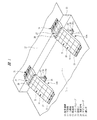
以下、本発明の実施の形態を図面に基づいて詳細に説明する。図1〜図4は、本発明の一実施の形態である段差通路を示す。図1に示されるように、段差通路10は下段面11とこれより高い上段面12とを有する段差部13に敷設され、トラックやフォークリフト等の作業用車両を下段面11と上段面12との間で案内するために使用される。図1に示されるように、段差通路10は複数台が相互に幅方向に連結された状態で段差部13に敷設される。図1においては、連結された段差通路10の幅寸法が車両の左右それぞれの車輪の幅よりも大きい幅となるように、3台の段差通路10を連結して1組の通路組立体10Aが組み立てられており、車両の左右の車輪に対応させて2組の通路組立体10Aが段差部13に敷設された状態が図1に示されている。
Hereinafter, embodiments of the present invention will be described in detail with reference to the drawings. 1 to 4 show a step passage according to an embodiment of the present invention. As shown in FIG. 1, the
このように、複数台の段差通路10により通路組立体10Aを形成するようにすると、各々の段差通路10の重量を作業者が手作業により運搬することができる重量に軽量化することができ、クレーン等の重機を使用することなく、段差通路10の敷設作業と撤去作業とを手作業により行うことができる。図1においては、通路組立体10Aを3台の段差通路10により形成するようにしているが、2台または4台の段差通路10によって通路組立体10Aを形成するようにしても良い。段差通路10の連結台数を増加することによって、相互に車幅が相違する複数種類の車両を通路組立体10Aの上を走行させることができる。
Thus, when the
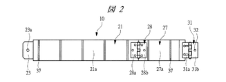
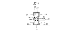
段差通路10は、図1〜図4に示されるように、メインスロープ21を有している。このメインスロープ21は、図4に示されるように、断面コの字形状の型鋼材により形成されており、上面壁21aとこれの左右両側に一体となった側壁21bを有し、例えば、幅寸法は20cm程度、長さ寸法は100cm程度となっている。したがって、3台の段差通路10を幅方向に連結すると、左右に所定の間隔を隔てて60cm幅の通路組立体10Aを段差部13に敷設することができる。ただし、各々の段差通路10の幅寸法を図示する場合よりも狭くすれば、1台の段差通路10をより軽量化することができる。
The
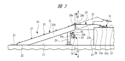
メインスロープ21の基端部の左右側壁には、図3に示されるように、下段面11に当接するように切欠き部22が形成されており、基端部には外方に突出する固定片23が設けられている。この固定片23には取付孔23aが形成されており、この取付孔23aには下段面11に取り付けられるピンやボルト等の締結具が貫通するようになっている。この締結具によりメインスロープ21は下段面11に固定される。メインスロープ21の先端部の下面には四角形の型鋼材からなる支持支柱24が固定されており、支持支柱24の下端部に設けられたフランジ部25には、図1に示されるように、下段面11に取り付けられるピンやボルト等の締結具26が貫通する取付孔25aが形成されている。
As shown in FIG. 3,
メインスロープ21の先端には、ヒンジ28を介してサブスロープ27が回動自在に連結されている。サブスロープ27はメインスロープ21と同一幅寸法の断面コの字形状の型鋼材により形成されており、上面壁27aとこれの左右両側に一体となった側壁27bを有し、長さ寸法は40〜50cm程度となっている。ヒンジ28はメインスロープ21の先端部にねじ固定される回動板28aとこれにピンを介して連結されサブスロープ27の基端部にねじ固定される回動板28bとを有しており、サブスロープ27はその基端部においてヒンジ28を介してメインスロープ21の先端に回動自在に連結されている。サブスロープ27の先端部の側壁27bには、図3に示されるように、上段面12の角部に当接する当接部29が形成されており、メインスロープ21と上段面12との間にはサブスロープ27が掛け渡されることになる。
A
サブスロープ27は、メインスロープ21に対して回動自在となっているので、図3において実線で示すように、ほぼ水平状態となって上段面12に掛け渡される状態と、図3において二点鎖線で示すように上向きに傾斜した状態となって上段面12に掛け渡される状態とのいずれにも設定される。これにより、段差部13の高さが相違しても、段差通路10を下段面11と上段面12との間に敷設することができる。サブスロープ27は、ヒンジ28によりメインスロープ21に取り付けられているので、ヒンジ28からサブスロープ27を取り外すことにより、任意の長さのサブスロープ27をメインスロープ21に連結することができる。
Since the
サブスロープ27の先端部にはヒンジ28と同様の部材からなる渡し片31が取り付けられており、この渡し片31はサブスロープ27の先端部にねじ固定される回動板31aとこれにピンを介して連結され上段面12に固定される回動板31bとを有しており、サブスロープ27の先端と上段面12との間には渡し片31が配置されることになる。回動板31bには、図2に示されるように、上段面12に取り付けられるピンやボルト等の締結具が貫通する取付孔32が形成されており、渡し片31を締結具により上段面12に固定することにより、サブスロープ27は上段面12に固定される。これにより、上段面12とサブスロープ27との間を円滑に車両が走行することができる。
A
支持支柱24には、図3および図4に示されるように、締結部材としてのクランプ部材33が取り付けられており、このクランプ部材33は支持支柱24に固定される固定ピース33aと、これに対してヒンジ34を介して回動自在に装着される回動ピース33bとを有している。固定ピース33aと回動ピース33bには、連結棒材35が入り込む凹面が形成されており、固定ピース33aと回動ピース33bの先端部とをねじ部材36により締結することによって、クランプ部材33により連結棒材35が締結される。これにより、図1に示すように、3台の段差通路10を連結棒材35により相互に連結することによって、1組の通路組立体10Aが組み立てられることになる。メインスロープ21とサブスロープ27の上面壁21a,27aには、棒状の滑り止め金具37が幅方向に伸びてそれぞれ固定されている。
As shown in FIGS. 3 and 4, a
このように、複数台の段差通路10を連結棒材35により連結することにより通路組立体10Aが組み立てられるようになっており、各々の段差通路10は作業者が手作業により運搬することができる重量に設定されている。したがって、3台の段差通路10をそれぞれ手作業により段差部13に配置した状態のもとで、連結棒材35により段差通路10を相互に連結するとともに、固定片23の取付孔23aに締結具を貫通させて下段面11に固定片23を固定し、支持支柱24のフランジ部25の取付孔25aに締結具26を貫通させて下段面11に支持支柱を固定する。これにより、3台の段差通路10からなる通路組立体10Aが段差部13を跨ぐようにして下段面11と上段面12との間に敷設されることになる。渡し片31は取付孔32を貫通する締結具により上段面12に固定することができるが、段差通路10のメインスロープ21が支持支柱24と固定片23の部分で下段面11に固定されているので、取付強度は十分であり、渡し片31は必要に応じて上段面12に締結される。一方、敷設された段差通路10を取り外す際には、それぞれの締結具を取り外すとともに、連結棒材35を取り外すことにより段差通路10を撤去することができる。
In this way, the
複数台の段差通路10を連結棒材35により連結するために、それぞれの支持支柱24には固定ピース33aと回動ピース33bとを有するクランプ部材33が設けられているが、連結棒材35を支持支柱24にねじ結合されるボルトにより締結するようにしても良い。その場合には、支持支柱24には締結部材としてクランプ部材33に代えてナットが設けられることになる。
In order to connect the plurality of stepped
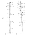
図5〜図7は、本発明の他の実施の形態である段差通路10aを示しており、この段差通路10aにおいては、上述した段差通路10を構成する部材と共通する部材には同一の符号が付されている。
FIGS. 5-7 has shown the level | step difference channel |
この段差通路10aは、メインスロープ21とサブスロープ27とに加えて2つの中間スロープ41,42を有しており、2つの中間スロープ41,42を介してメインスロープ21とサブスロープ27とが連結されている。このように、段差通路10aをメインスロープ21と2つの中間スロープ41,42とサブスロープ27とにより形成することによって、段差部13の高さが図1に示す場合と同一の場合でも、段差通路10aの全長を長くして全体の傾斜角度を小さい角度とすることができる。
The
段差通路10aは全長が長くなるので、中間スロープ41,42は連結部40により相互に取り外し自在に連結され、中間スロープ41とメインスロープ21は連結部40により相互に取り外し自在に連結されており、中間スロープ42とサブスロープ27は連結部40により相互に取り外し自在に連結されている。メインスロープ21等の幅寸法は、それぞれ上述した段差通路10と同様に20cm程度となっているのに対し、長さ寸法はメインスロープ21が約170cm、中間スロープ41,42が約125cm、サブスロープ27が約80cmとなっており、段差通路10よりも長い寸法となっている。しかしながら、段差通路10aを構成する4つのスロープがそれぞれ連結部40を介して相互に取り外し自在つまり分離自在となっているので、4つのスロープのそれぞれを作業者は手作業で運搬することができる。
Since the
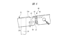
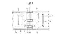
図6および図7は、メインスロープ21と中間スロープ41の連結部40を示す拡大図であり、メインスロープ21の先端部の側壁21bは上面壁21aよりも突出しており、突出した左右の側壁21bの間には連結ピン43が配置されている。この連結ピン43は支持支柱24に固定されたブラケット44を貫通してブラケット44に固定されている。一方、中間スロープ41の基端部には、外側のアングル材45が固定され、このアングル材45には内側のアングル材46が固定されており、対をなす両方のアングル材45,46により連結ピン43が収容される収容溝47が形成されている。それぞれのアングル材45,46は、ブラケット44を介してメインスロープ21の幅方向両側に一対ずつ2対設けられている。
6 and 7 are enlarged views showing the connecting
したがって、メインスロープ21に対して上側から中間スロープ41を下降移動させると、収容溝47内に連結ピン43が入り込み、連結ピン43を介してメインスロープ21と中間スロープ41は相互に連結される。この連結作業は段差通路10aを組み立てる現場において行うことができる。幅方向一方側のアングル材45,46には収容溝47を横断するようにロックピン48が取り外し自在に装着されるようになっており、これを取り付けることにより連結ピン43が収容溝47から外れるのが防止される。
Therefore, when the
図6および図7は、メインスロープ21と中間スロープ41とを取り外し自在に連結するための連結部40の構造を示すが、中間スロープ41の先端部と中間スロープ42の基端部にも同様の構造の連結部40が設けられており、中間スロープ42の先端部とサブスロープ27の基端部にも同様の構造の連結部40が設けられている。したがって、中間スロープ41の先端部には連結ピン43が設けられ、中間スロープ42の先端部にも連結ピン43が設けられている。
6 and 7 show the structure of the connecting
中間スロープ41の先端部にはこれを下段面11に支持するための支持支柱51が取り付けられており、同様に中間スロープ42の先端部にはこれを下段面11に支持するための支持支柱52が取り付けられている。中間スロープ42の先端部と下段面11との間の高さは、中間スロープ41の先端部と下段面11との間の高さよりも高いので、支持支柱52の下側にはスペーサ53が取り付けられている。これにより、同一長さの型鋼材を用いることにより、支持支柱51,52を形成することができる。ただし、中間スロープ42の支持支柱52としては、スペーサ53を含めた長さの型鋼材を使用するようにしても良い。
A
支持支柱51,52には、上述したクランプ部材33と同一構造のクランプ部材33が取り付けられており、このクランプ部材33により連結棒材35を締結することによって、例えば、3台の段差通路10aを連結し、図1に示した場合と同様にして段差部13に敷設される。幅方向に隣り合う他の段差通路10aの支持支柱51,52を相互に連結棒材35により連結する方式としては、上述のように、連結棒材35をボルトにより支持支柱51,52に連結するようにしても良く、その場合には支持支柱51,52にはボルトがねじ結合されるナットが締結部材として設けられることになる。
A
中間スロープ41,42とサブスロープ27には、図5に示されるように、取手54が取り付けられており、これらを運搬するときには作業者は取手54の部分で把持することになる。
As shown in FIG. 5, a
段差通路10aを段差部13に敷設するには、メインスロープ21を下段面11の上に配置し、メインスロープ21の先端部に中間スロープ41の基端部を連結する。次いで、中間スロープ41の先端部に中間スロープ42の基端部を連結し、中間スロープ42の先端部にサブスロープ27の基端部を連結する。これにより、1台の段差通路10aが組み立てられ、同様にして他の2台の段差通路10aを組み立てる。次いで、それぞれの段差通路10aを締結具により下段面11と上段面12に締結するとともに、3台の段差通路10aの中間スロープ41を連結棒材35により相互に連結し、中間スロープ42を他の連結棒材35により相互に連結する。このようにして、3台の段差通路10aからなる通路組立体が組み立てられる。通路組立体は図1に示すように車両の左右両輪に対応させて2組段差部13に敷設される。
In order to lay the
図5および図6に示す段差通路10aは、2つの中間スロープ41,42をメインスロープ21とサブスロープ27との間に配置するようにしているが、段差部13の高さに応じて1つの中間スロープを有する形態、3つあるいはそれ以上の中間スロープを有する形態のいずれにも設定される。3つの中間スロープが用いられる場合には、中間スロープ42の先端に連結される中間スロープの支持支柱には図5(B)に示されるスペーサ53よりも高さの高いスペーサが使用される。
In the
中間スロープ41,42を用いることなく、メインスロープ21に対して直接サブスロープ27を連結すると、図1〜図4に示した形態の段差通路10となる。ただし、メインスロープ21とサブスロープ27とを連結する連結部の構造は段差通路10とは相違することになる。
When the
本発明は前記実施の形態に限定されるものではなく、その要旨を逸脱しない範囲で種々変更可能である。例えば、図1〜図4に示す段差通路10においても、メインスロープ21とサブスロープ27とを図6および図7に示す連結部40により分離自在に連結するようにしても良い。また、段差通路10aのメインスロープ21、中間スロープ41,42およびサブスロープ27に、図2および図3に示した滑り止め金具37を取り付けるようにしても良い。
The present invention is not limited to the above-described embodiment, and various modifications can be made without departing from the scope of the invention. For example, in the
10,10a 段差通路
10A 通路組立体
11 下段面
12 上段面
13 段差部
21 メインスロープ
23 固定片
24 支持支柱
25 フランジ部
26 締結具
27 サブスロープ
28 ヒンジ
29 当接部
31 渡し片
33 クランプ部材
34 ヒンジ
35 連結棒材
36 ねじ部材
40 連結部
41,42 中間スロープ
43 連結ピン
44 ブラケット
45,46 アングル材
47 収納溝
48 ロックピン
51,52 支持支柱
54 取手
10,
Claims (4)
基端部に前記下段面に固定される固定片が設けられ、先端部の下面に前記下段面に支持される支持支柱が固定されたメインスロープと、
前記メインスロープの先端に基端部において回動自在に連結され、先端部が前記上段面に当接する当接部が形成されたサブスロープと、
相互に幅方向に隣り合って配置される複数の前記メインスロープにおける前記支持支柱を相互に連結し、1組の通路組立体を組み立てる連結棒材と、を有し、
前記車両の前記車輪幅よりも大きい幅となるように複数個連結して前記下段面と前記上段面との間に敷設することを特徴とする段差通路。 A step passage laid between a lower step surface and an upper step surface higher than the lower step surface in a state where a plurality of vehicles are connected in the width direction, and guides the wheels of the vehicle,
A main slope in which a fixed piece fixed to the lower step surface is provided at the base end portion, and a support column supported by the lower step surface is fixed to the lower surface of the distal end portion;
A sub-slope that is pivotally connected to a distal end of the main slope at a proximal end portion, and a distal portion is formed with a contact portion that contacts the upper surface;
A connecting bar for connecting the support struts in the plurality of main slopes arranged adjacent to each other in the width direction and assembling a set of passage assemblies;
A step passage, wherein a plurality of the steps are connected so as to have a width larger than the wheel width of the vehicle and are laid between the lower step surface and the upper step surface.
Priority Applications (1)
| Application Number | Priority Date | Filing Date | Title |
|---|---|---|---|
| JP2009186320A JP5545708B2 (en) | 2009-08-11 | 2009-08-11 | Step passage |
Applications Claiming Priority (1)
| Application Number | Priority Date | Filing Date | Title |
|---|---|---|---|
| JP2009186320A JP5545708B2 (en) | 2009-08-11 | 2009-08-11 | Step passage |
Publications (2)
| Publication Number | Publication Date |
|---|---|
| JP2011038307A JP2011038307A (en) | 2011-02-24 |
| JP5545708B2 true JP5545708B2 (en) | 2014-07-09 |
Family
ID=43766336
Family Applications (1)
| Application Number | Title | Priority Date | Filing Date |
|---|---|---|---|
| JP2009186320A Active JP5545708B2 (en) | 2009-08-11 | 2009-08-11 | Step passage |
Country Status (1)
| Country | Link |
|---|---|
| JP (1) | JP5545708B2 (en) |
Cited By (1)
| Publication number | Priority date | Publication date | Assignee | Title |
|---|---|---|---|---|
| KR102061323B1 (en) * | 2019-07-12 | 2019-12-31 | 홍영광 | Slope way for module |
Families Citing this family (7)
| Publication number | Priority date | Publication date | Assignee | Title |
|---|---|---|---|---|
| JP6266572B2 (en) * | 2015-08-28 | 2018-01-24 | 株式会社 シコク | Slope device |
| JP2017198060A (en) * | 2016-02-08 | 2017-11-02 | ジー・オー・ピー株式会社 | Slope device |
| JP6522541B2 (en) * | 2016-03-31 | 2019-05-29 | 株式会社 シコク | Slope device |
| JP6769128B2 (en) * | 2016-06-21 | 2020-10-14 | 株式会社大林組 | Shield tunnel lining and segments used for lining |
| KR101871371B1 (en) * | 2018-01-10 | 2018-06-26 | (주)상지엔지니어링건축사사무소 | Stairs apparatus for building |
| JP6830711B1 (en) * | 2020-09-24 | 2021-02-17 | 株式会社伸光リース | Girder support device |
| JP7687678B2 (en) * | 2021-11-02 | 2025-06-03 | ジャパン スチールス グループ株式会社 | Protective cover |
Family Cites Families (4)
| Publication number | Priority date | Publication date | Assignee | Title |
|---|---|---|---|---|
| JP3375463B2 (en) * | 1995-07-28 | 2003-02-10 | 和則 春田 | Retractable slope |
| JPH11247464A (en) * | 1998-02-27 | 1999-09-14 | Sekisui Chem Co Ltd | Construction stand and building construction method |
| JP4163153B2 (en) * | 2004-07-09 | 2008-10-08 | 大一機材工業株式会社 | Scaffold for construction |
| JP2008045382A (en) * | 2006-08-11 | 2008-02-28 | Hiroaki Sugiyama | Step slope |
-
2009
- 2009-08-11 JP JP2009186320A patent/JP5545708B2/en active Active
Cited By (1)
| Publication number | Priority date | Publication date | Assignee | Title |
|---|---|---|---|---|
| KR102061323B1 (en) * | 2019-07-12 | 2019-12-31 | 홍영광 | Slope way for module |
Also Published As
| Publication number | Publication date |
|---|---|
| JP2011038307A (en) | 2011-02-24 |
Similar Documents
| Publication | Publication Date | Title |
|---|---|---|
| JP5545708B2 (en) | Step passage | |
| US8376439B2 (en) | Paneled deck assembly for transporter vehicle | |
| US11407623B2 (en) | Configurable lift system | |
| JP3177555U (en) | Assembling staircase | |
| JP2011140802A (en) | Construction machine | |
| CN112298224B (en) | Operation vehicle for track beam | |
| EP2915771B1 (en) | Forklift head-guard structure | |
| EP3609740A1 (en) | Device for supporting a two-wheeled vehicle on a structural part | |
| KR100367028B1 (en) | A self propelled working platform for construction and maintenance of bridge | |
| JP5159926B2 (en) | Parking block | |
| CN215904477U (en) | Movable and easy-to-install rail conveyor | |
| JP5260346B2 (en) | Moving shelf and its underframe | |
| CN210113165U (en) | Crawler belt shield and crawler belt excavator | |
| KR20100067788A (en) | The equipment to change the fork length | |
| JP7208532B2 (en) | Prefabricated temporary staircase | |
| JP2003055905A (en) | Footboard for temporary road mat | |
| JP2003252184A (en) | Travel assisting device | |
| US20240116577A1 (en) | High Clearance Floorboards for an All Terrain Vehicle (ATV) | |
| JP7687678B2 (en) | Protective cover | |
| CN214929691U (en) | Material transportation device is used in road and bridge construction | |
| CN223030874U (en) | Vehicle access ladder installed on the side of the spare wheel bracket | |
| JPH09112041A (en) | Moving safety net | |
| US20080050183A1 (en) | Slide rail panel pushing assembly | |
| JP7557353B2 (en) | Wheeled work vehicle | |
| JP4133177B2 (en) | Bicycle parking device cable routing structure |
Legal Events
| Date | Code | Title | Description |
|---|---|---|---|
| A621 | Written request for application examination |
Free format text: JAPANESE INTERMEDIATE CODE: A621 Effective date: 20120802 |
|
| A977 | Report on retrieval |
Free format text: JAPANESE INTERMEDIATE CODE: A971007 Effective date: 20130628 |
|
| A131 | Notification of reasons for refusal |
Free format text: JAPANESE INTERMEDIATE CODE: A131 Effective date: 20130702 |
|
| A521 | Request for written amendment filed |
Free format text: JAPANESE INTERMEDIATE CODE: A523 Effective date: 20130830 |
|
| TRDD | Decision of grant or rejection written | ||
| A01 | Written decision to grant a patent or to grant a registration (utility model) |
Free format text: JAPANESE INTERMEDIATE CODE: A01 Effective date: 20140507 |
|
| A61 | First payment of annual fees (during grant procedure) |
Free format text: JAPANESE INTERMEDIATE CODE: A61 Effective date: 20140508 |
|
| R150 | Certificate of patent or registration of utility model |
Ref document number: 5545708 Country of ref document: JP Free format text: JAPANESE INTERMEDIATE CODE: R150 |
|
| R250 | Receipt of annual fees |
Free format text: JAPANESE INTERMEDIATE CODE: R250 |
|
| R250 | Receipt of annual fees |
Free format text: JAPANESE INTERMEDIATE CODE: R250 |
|
| R250 | Receipt of annual fees |
Free format text: JAPANESE INTERMEDIATE CODE: R250 |
|
| R250 | Receipt of annual fees |
Free format text: JAPANESE INTERMEDIATE CODE: R250 |
|
| R250 | Receipt of annual fees |
Free format text: JAPANESE INTERMEDIATE CODE: R250 |
|
| R250 | Receipt of annual fees |
Free format text: JAPANESE INTERMEDIATE CODE: R250 |
|
| R250 | Receipt of annual fees |
Free format text: JAPANESE INTERMEDIATE CODE: R250 |
|
| R250 | Receipt of annual fees |
Free format text: JAPANESE INTERMEDIATE CODE: R250 |
|
| R250 | Receipt of annual fees |
Free format text: JAPANESE INTERMEDIATE CODE: R250 |