JP5544783B2 - Tape supply device and tape printer provided with the same - Google Patents
Tape supply device and tape printer provided with the same Download PDFInfo
- Publication number
- JP5544783B2 JP5544783B2 JP2009187152A JP2009187152A JP5544783B2 JP 5544783 B2 JP5544783 B2 JP 5544783B2 JP 2009187152 A JP2009187152 A JP 2009187152A JP 2009187152 A JP2009187152 A JP 2009187152A JP 5544783 B2 JP5544783 B2 JP 5544783B2
- Authority
- JP
- Japan
- Prior art keywords
- tape
- core
- rotation
- printing
- cartridge
- Prior art date
- Legal status (The legal status is an assumption and is not a legal conclusion. Google has not performed a legal analysis and makes no representation as to the accuracy of the status listed.)
- Expired - Fee Related
Links
Images


Classifications
-
- B—PERFORMING OPERATIONS; TRANSPORTING
- B41—PRINTING; LINING MACHINES; TYPEWRITERS; STAMPS
- B41J—TYPEWRITERS; SELECTIVE PRINTING MECHANISMS, i.e. MECHANISMS PRINTING OTHERWISE THAN FROM A FORME; CORRECTION OF TYPOGRAPHICAL ERRORS
- B41J3/00—Typewriters or selective printing or marking mechanisms characterised by the purpose for which they are constructed
- B41J3/407—Typewriters or selective printing or marking mechanisms characterised by the purpose for which they are constructed for marking on special material
- B41J3/4075—Tape printers; Label printers
Landscapes
- Printers Characterized By Their Purpose (AREA)
- Controlling Sheets Or Webs (AREA)
- Controlling Rewinding, Feeding, Winding, Or Abnormalities Of Webs (AREA)
- Handling Of Continuous Sheets Of Paper (AREA)
- Accessory Devices And Overall Control Thereof (AREA)
- Impression-Transfer Materials And Handling Thereof (AREA)
Description
本発明は、テープコアにロール状に巻回したテープ状部材を繰り出して送るテープ供給装置およびこれを備えたテープ印刷装置に関する。 The present invention relates to a tape supply device that feeds and feeds a tape-shaped member wound around a tape core in a roll shape, and a tape printing apparatus including the tape supply device.
従来、巻回されたテープ状部材の終了端の近傍に形成された被検出部を、サーマルヘッドの下流側のカッターに隣接して設けられたフォトセンサー(光センサー:回転検出手段)により検出することで、テープ状部材が終了したことを認識可能なテープ供給装置(テープ印字装置)が知られている(特許文献1参照)。
このテープ供給装置では、被検出部が、テープ状部材においてフォトセンサーの光が通過可能な孔(または透明部分)として設けられており、フォトセンサーが被検出部を検出する(テープエンド検出)と、テープ状部材の送り駆動およびテープ状部材に対する印刷が停止される。この場合、被検出部からテープ状部材の終了端までの長さが、フォトセンサーの検出位置からサーマルヘッドの印刷位置までの長さ(距離)と等しく構成され、印刷位置にテープ状部材が存在しない状態で印刷が行われることを防止できるようになっている。
Conventionally, a detected portion formed in the vicinity of the end of the wound tape-like member is detected by a photosensor (photosensor: rotation detection means) provided adjacent to a cutter on the downstream side of the thermal head. Thus, a tape supply device (tape printer) capable of recognizing the end of the tape-like member is known (see Patent Document 1).
In this tape supply device, the detected part is provided as a hole (or transparent part) through which the light of the photosensor can pass in the tape-like member, and the photosensor detects the detected part (tape end detection). The feeding of the tape-like member and the printing on the tape-like member are stopped. In this case, the length from the detected part to the end of the tape-like member is configured to be equal to the length (distance) from the detection position of the photosensor to the printing position of the thermal head, and the tape-like member exists at the printing position. Thus, it is possible to prevent printing from being performed.
しかし、上記のようなテープ供給装置では、テープ状部材そのものに被検出部を形成しなければならず、テープ状部材の製造コストの増大が問題となっていた。また、テープ状部材が透明或いは半透明である場合には、光センサー等の検出手段では被検出部の検出が非常に困難なものとなり、テープ種別によってはテープエンド(被検出部)を正確に検出することができなかった。さらに、上記した検出手段では、テープ状部材の搬送中の状態を検出することができず、適切にテープ状部材の送りが行われているか否かを検出することができなかった。 However, in the tape supply apparatus as described above, the detected portion must be formed on the tape-like member itself, and an increase in the manufacturing cost of the tape-like member has been a problem. In addition, when the tape-like member is transparent or translucent, it becomes very difficult to detect the detected part by a detection means such as an optical sensor. Depending on the type of tape, the tape end (detected part) can be accurately set. It could not be detected. Further, the above-described detection means cannot detect the state of the tape-shaped member being conveyed, and cannot detect whether or not the tape-shaped member is being fed appropriately.
本発明は、テープ状部材に加工を施すことなく、確実にテープエンドを検出することができると共に、テープ状部材のテープ送り状態を把握することのできるテープ供給装置およびこれを備えたテープ印刷装置を提供することを目的とする。 The present invention relates to a tape supply device capable of reliably detecting a tape end without processing the tape-like member and grasping a tape feed state of the tape-like member, and a tape printing apparatus provided with the tape supply device The purpose is to provide.
本発明のテープ供給装置は、テープ状部材をテープコアに巻回してなるテープ体を、カートリッジケースに収容したテープカートリッジと、テープカートリッジが着脱自在に装着される装置本体と、を備え、テープコアは、外周面にテープ状部材が巻回され、内周面でカートリッジケースに軸支された外筒部と、装置本体側の端部に、少なくとも1つの被検出部を有する内筒部と、外筒部と内筒部とを連結する環状連結部と、を有し、装置本体は、テープコアからテープ状部材を繰り出しながら送るテープ送り手段と、被検出部と協働し、テープコアの回転停止を含む回転状態を検出する回転検出手段と、を有していることを特徴とする。 A tape supply device of the present invention comprises a tape body in which a tape-like member is wound around a tape core, a tape cartridge accommodated in a cartridge case, and an apparatus main body to which the tape cartridge is detachably mounted . A tape-shaped member is wound around the outer peripheral surface, and is supported by the cartridge case on the inner peripheral surface, an inner cylindrical portion having at least one detected portion at an end on the apparatus main body side, and an outer cylinder The apparatus main body includes a tape feeding means that feeds the tape-shaped member from the tape core while feeding the tape-like member, and a detected portion, and includes a rotation stop of the tape core. And a rotation detecting means for detecting a rotation state.
この構成によれば、テープコアと協働して、テープコアの回転停止を含む回転状態を検出できるため、テープ状部材が繰り出されながら送られる状態を、テープコアを介して把握することができる。例えば、テープ送り手段に同期してテープコアの回転が検出されれば、テープ状部材が正常に繰り出され且つ送られていることが、把握できる。一方、テープコアの回転停止が検出されれば、テープ状部材を使い切ったこと(テープエンド)やテープ状部材の異常な送り状態であることが把握できる。これにより、テープ状部材自体にテープエンドを示すための加工を施す必要がなく、正確にテープエンドの検出等を行うことができ、テープ状部材(ひいてはテープ体)を安価に製造することができる。 According to this configuration, since the rotation state including the rotation stop of the tape core can be detected in cooperation with the tape core, the state in which the tape-shaped member is fed while being fed can be grasped via the tape core. For example, if rotation of the tape core is detected in synchronization with the tape feeding means, it can be grasped that the tape-like member is normally fed out and fed. On the other hand, if the rotation stop of the tape core is detected, it can be grasped that the tape-like member has been used up (tape end) or that the tape-like member is in an abnormal feeding state. Thereby, it is not necessary to perform processing for indicating the tape end on the tape-shaped member itself, the tape end can be accurately detected, and the tape-shaped member (and thus the tape body) can be manufactured at low cost. .
この場合、装置本体は、テープ送り手段の駆動を制御する制御手段を、更に有し、制御手段は、テープ送り手段の送り駆動時において、回転検出手段がテープコアの回転停止を検出した場合に、テープ送り手段の駆動を停止させることが好ましい。 In this case, the apparatus main body further has a control means for controlling the drive of the tape feeding means, and the control means, when the rotation detecting means detects the rotation stop of the tape core during the feed driving of the tape feeding means, It is preferable to stop the drive of the tape feeding means.
この構成によれば、テープ状部材を使い切った後に、テープ状部材の供給が強制的に停止されるため、ユーザーは、テープエンドやテープ状部材の送りの異常等を認識することができる。これにより、テープエンドだけでなく、テープ状部材のテープコアに対する巻きに弛みや切れ等が生じていること、または搬送中のテープ状部材に弛みや絡み等が生じていることを検出することができる。また、例えば、テープ状部材に印刷等の処理を行うような場合には、テープ状部材の供給停止をトリガーとして、その処理の停止を行うこともできる。 According to this configuration, since the supply of the tape-shaped member is forcibly stopped after the tape-shaped member is used up, the user can recognize an abnormality in feeding of the tape end or the tape-shaped member. Thereby, it is possible to detect that not only the tape end but also the winding of the tape-shaped member with respect to the tape core is loosened or cut, or that the tape-shaped member being conveyed is loosened or entangled. . Further, for example, when processing such as printing is performed on the tape-shaped member, the processing can be stopped using the supply stop of the tape-shaped member as a trigger.
また、装置本体は、テープ送り手段の駆動を制御する制御手段と、装着されたテープ体の種別を検出する種別検出手段と、を更に有し、制御手段は、テープ体の種別毎の各種パラメーターを記憶した制御テーブルを有し、種別検出手段の検出結果に基づき、制御テーブルを参照し、テープ送り手段の送り駆動速度、回転検出手段の検出結果および制御テーブルの参照結果から、テープ状部材の巻き残量を算出することが好ましい。 The apparatus main body further includes control means for controlling the drive of the tape feeding means, and type detection means for detecting the type of the tape body mounted, and the control means includes various parameters for each type of tape body. And a control table is referred to based on the detection result of the type detection means, and from the feed drive speed of the tape feed means, the detection result of the rotation detection means and the reference result of the control table, It is preferable to calculate the remaining winding amount.
この構成によれば、テープ状部材の構成(色や種類等)によらず、簡単にテープ状部材の巻き残量を算出することができる。
なお、回転検出手段の回転状態とテープ状部材の巻き残量との相関関係を示す対応表を制御テーブルとして用いてもよい。この場合、回転検出手段の検出結果から制御テーブルを参照するだけで巻き残量を求めることができる。
According to this configuration, the remaining winding amount of the tape-shaped member can be easily calculated regardless of the configuration (color, type, etc.) of the tape-shaped member.
A correspondence table showing the correlation between the rotation state of the rotation detecting means and the remaining winding amount of the tape-like member may be used as the control table. In this case, the remaining winding amount can be obtained simply by referring to the control table from the detection result of the rotation detecting means.
この場合、回転検出手段は、被検出部に臨む光センサーであることが好ましい。 In this case, rotation detecting means is preferably a light sensor facing the part to be detected.
他にも、回転検出手段は、被検出部に接触し、オンまたはオフするマイクロスイッチであることが好ましい。
Additional rotation detecting means, in contact with the portion to be detected is preferably a micro switch to on or off.
これらの構成によれば、簡単な構造でテープコアの回転を正確に検出することができる。これにより、テープエンドの検出もしくはテープ状部材の送り状態またはテープ状部材の巻き残量の算出を精度良く行うことができる。 According to these configurations, the rotation of the tape core can be accurately detected with a simple structure. Thereby, it is possible to accurately detect the tape end, calculate the feeding state of the tape-shaped member, or calculate the remaining winding amount of the tape-shaped member.
この場合、装置本体は、テープ状部材の回転状態を報知する報知手段を、更に有していることが好ましい。 In this case, it is preferable that the apparatus main body further has an informing means for informing the rotation state of the tape-like member.
報知手段により、ユーザーは、テープ体の交換時期や使用に必要な量のテープ状部材が残っているか否か等を容易に確認することができる。
なお、巻き残量だけでなく、テープエンドである旨およびテープ状部材が弛んでいる旨を報知するようにしてもよい。また、報知手段としては、LED等の警告灯や、スピーカーからの警告音等が考えられるが、装置ディスプレイにインジケーター表示するようにしてもよい。
By the notification means, the user can easily confirm whether or not the tape body replacement time and the amount of tape-like members necessary for use remain.
Not only the remaining amount of winding but also the fact that it is a tape end and that the tape-like member is loose may be notified. Further, as the notification means, warning lights such as LEDs, warning sounds from speakers, and the like can be considered, but an indicator may be displayed on the apparatus display.
本発明のテープ印刷装置は、上記したテープ供給装置と、繰り出され送られるテープ状部材に印刷を行うテープ印刷手段と、を備えたことを特徴とする。 The tape printer of the present invention includes the above-described tape supply device, and a tape printing unit that performs printing on a tape-shaped member that is fed out and sent.
この構成によれば、テープ状部材をいわゆる印刷テープに適用した場合に、印刷テープの繰り出し状態、すなわち印刷テープが正常に送られているか否かを正確に把握することができる。このため、例えば、テープ状部材を使い切ったことやテープ状部材の弛みや絡み等が生じていることを検出し、自動的にテープ状部材の送りを停止することができる。これにより、テープ状部材が供給されていないにもかかわらず、テープ印刷手段により印刷処理が続けられる等の問題を回避することができる。 According to this configuration, when the tape-like member is applied to a so-called printing tape, it is possible to accurately grasp whether or not the printing tape is fed out, that is, whether or not the printing tape is normally fed. For this reason, for example, it can be detected that the tape-like member has been used up or that the tape-like member is loosened or entangled, and the feeding of the tape-like member can be automatically stopped. Thereby, it is possible to avoid problems such as the printing process being continued by the tape printing means even though the tape-like member is not supplied.
以下、添付の図面を参照しながら、本発明のテープ印刷装置について説明する。このテープ印刷装置は、装着したテープカートリッジから印刷テープ(テープ状部材)およびインクリボンを繰り出し、張りを与えた状態で併走させながら印刷を行い、印刷テープの印刷済み部分を切断して、ラベル(テープ片)を作成するものである。 Hereinafter, the tape printer of the present invention will be described with reference to the accompanying drawings. This tape printing apparatus feeds a printing tape (tape-shaped member) and an ink ribbon from a mounted tape cartridge, performs printing while running in a tensioned state, cuts the printed portion of the printing tape, and labels ( Tape piece).
(第1の実施例)
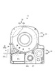
図1を参照して、テープ印刷装置1について説明する。図1は、テープ印刷装置1の開蓋状態の外観斜視図である。テープ印刷装置1は、印刷テープ21aやインクリボン22a等を収容したテープカートリッジ13が着脱自在に装着される装置本体14を備えたテープ供給装置11と、繰り出されて送られる印刷テープ21aに印刷を行うテープ印刷手段12と、を備えている。また、テープ印刷装置1には、印刷処理等を統括的に制御する制御装置15(図5参照)を備えている。
(First embodiment)
The
図2は、上ケース20aを破断したテープカートリッジ13の平面図である。図1および図2に示すように、テープカートリッジ13は、上ケース20aと下ケース20bとからなる樹脂製のカートリッジケース20により、その外殻が形成されている。また、テープカートリッジ13は、印刷テープ21aをテープコア21bに巻回してなるテープ体21と、インクリボン22aをリボンコア22bに巻回してなるリボン体22と、使用後のインクリボン22aを巻き取る巻取りコア23と、印刷テープ21aをテープ体21から繰り出して送るプラテンローラー24と、をカートリッジケース20の内部に収容している。なお、図2において、テープ体21は上側中央に、リボン体22は下側右側に、そして巻取りコア23は下側中央に、それぞれ配置されている。テープカートリッジ13を装置本体14に装着すると、印刷テープ21aには、テープ印刷手段12のサーマルヘッド12aがプラテンローラー24に対峙するようになっている。
FIG. 2 is a plan view of the
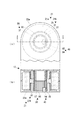
図3は、図1に示すテープカートリッジ13のA−A線における断面斜視図である。また、図4は、テープカートリッジ13の一部を模式的に示した平面図(a)および図4(a)に示すテープカートリッジ13のA−A線における断面図(b)である。図3および図4に示すように、上ケース20aには、テープコア21bが係合する上コア軸31と、上コア軸31の内側において、後述する位置決め突起53が係合するコア軸受部32と、が内部に向かって突設されている。なお、上コア軸31とコア軸受部32とは、同軸上に設けられている。上コア軸31およびコア軸受部32は、いずれも円筒状に形成され、上ケース20aと一体に成形されている。同様に、下ケース20bには、テープコア21bを軸支する円筒状の下コア軸33が内部に向かって突設されている。下コア軸33は、下ケース20bと一体に成形され、上コア軸31と対峙している。下コア軸33の内側には、装置本体14と連通する円形の検出開口34が形成されており、この検出開口34には、後述する回転検出手段46が臨むようになっている。
FIG. 3 is a cross-sectional perspective view taken along line AA of the
テープコア21b、リボンコア22bおよび巻取りコア23は、それぞれ円筒状に形成されており、上ケース20aと下ケース20bとの間に配置されている。また、図示では省略したが、テープコア21b、リボンコア22bおよび巻取りコア23には、回転止め機構が組み込まれており、テープカートリッジ13を装置本体14に装着すると、回転止めが解除されるようになっている。
Each of the
テープコア21bは、外筒部35と内筒部36と、これらを中間位置で連結する環状連結部37とで一体に形成され、全体として二重の円筒形状を為している。外筒部35の外側には、印刷テープ21aが巻かれており、外筒部35の内側には、環状連結部37を上下から挟むように、上記した上コア軸31および下コア軸33が、それぞれ係合するようになっている。
The
内筒部36の下部には、後述する回転検出手段46による検出対象となる被検出部38が一体に形成されている。第1の実施例の被検出部38は、内筒部36の周方向において、矩形の切欠きからなる複数の光透過部38aと、当該切欠き以外の複数の光遮蔽部38bと、を交互に等間隔に連ねて構成されている。そして、テープコア21b(被検出部38)の回転を、後述する回転検出手段46が検出することでパルス信号が生成される。なお、光透過部38aおよび光遮蔽部38bの形成数は、任意であり、それぞれ少なくとも1つ構成されていればよく、等間隔でなくてもよい。すなわち、被検出部38は、回転検出手段46からの光を透過する部分、または光を遮蔽する部分が、少なくとも1つ形成されていればよい。また、被検出部38(光透過部38aおよび光遮蔽部38b)の形成位置は、内筒部36の周方向に限定されるものではなく、テープコア21bの回転に伴い回転し、且つ後述する回転検出手段46と協働し、テープコア21bの回転を検出できる位置に設けられていればよい。さらに、光透過部38aは、矩形に限らず任意の形状の切欠きでよく、また、切欠きに代えて開口を形成してもよい。他にも、テープコア21bが透明であれば、複数の光透過部38aおよび複数の光遮蔽部38bを縞模様のシール(テープ)で構成し、内筒部36に貼着するようにしてもよい。
A
テープコア21bから繰り出された印刷テープ21aは、テープガイドピン26に案内されてプラテンローラー24に至る。一方、リボンコア22bから繰り出されたインクリボン22aは、テンションが付与されながら第1リボンピン27および第2リボンピン28に案内され、プラテンローラー24に至る。そして、サーマルヘッド12aが対峙するプラテンローラー24の部分で、インクリボン22aは、印刷テープ21aに重なって併走しながらサーマルヘッド12aにより印刷処理が行われる。印刷後の印刷テープ21aは、カートリッジケース20の側面に形成したテープ送出口29からテープカートリッジ13の外部に送り出される。一方、インクリボン22aは、カートリッジケース20内を回って巻取りコア23に巻き取られる。
The
続いて、テープ供給装置11の主要部を為す装置本体14について説明する。図1に示すように、装置本体14は、装置ケース41により外殻が形成され、テープカートリッジ13を装着するカートリッジ装着部42が形成されている。また、装置本体14は、ユーザーが直接操作する入力装置であるキーボード43aおよびキーボード43aからの入力結果等を表示するディスプレイ43b(報知手段)を有する操作手段43と、テープカートリッジ13から印刷テープ21aを繰り出しながら送るテープ送り手段44と、印刷済みの印刷テープ21aを切断するカッター手段45と、テープコア21bと協働し、テープコア21bの回転停止を含む回転状態を検出する回転検出手段46(図5参照)と、を備えている。
Next, the apparatus
キーボード43aは、装置ケース41の前半部上面に、ディスプレイ43bは、装置ケース41の後半部右上面に、それぞれ配設されている。また、装置ケース41の後半部左上面には、開閉蓋47が設けられており、開閉蓋47の内側には、カートリッジ装着部42が窪入形成されている。カートリッジ装着部42には、隠蔽するようにして、上記したテープ印刷手段12およびテープ送り手段44が配設されている。また、カートリッジ装着部42の隅部には、後述するテープ識別センサー79(図5参照)が配設されており、カートリッジケース20の種別等を識別できるようになっている。
The
テープ送り手段44は、プラテンローラー24を駆動して印刷テープ21aを送るプラテン駆動軸51と、巻取りコア23を駆動してインクリボン22aを巻き取る巻取り駆動軸52と、テープコア21bを位置決めする位置決め突起53と、プラテン駆動軸51および巻取り駆動軸52を同期回転させる送りモーター54(図5参照)と、送りモーター54の駆動力をプラテン駆動軸51および巻取り駆動軸52に伝達するギヤ列(図示省略)と、を備えている。なお、送りモーター54およびギヤ列は、カートリッジ装着部42の底板の下部空間に内蔵されている。
The tape feeding means 44 positions the
テープカートリッジ13をカートリッジ装着部42に装着すると、位置決め突起53がコア軸受部32に係合し、プラテン駆動軸51がプラテンローラー24に係合し、巻取り駆動軸52が巻取りコア23に係合すると共に、サーマルヘッド12aが、印刷テープ21aおよびインクリボン22aを挟んでプラテンローラー24に当接し、印刷待機状態となる。
When the
装置ケース41の左側部には、カートリッジ装着部42と装置外部とを連通するテープ排出口48が形成されている。このテープ排出口48には、カッター手段45(切刃)が臨んでおり、カッターモーター45aを駆動することで、テープ排出口48から送り出される印刷テープ21aの印刷済み部分がテープ幅方向に切断され、テープ片(ラベル)が作成される。
On the left side of the device case 41, a
図3および図4に示すように、回転検出手段46は、光などの電磁気的エネルギーを検出する光センサーで構成されている。この光センサーの一例として、第1の実施例では、発光素子Eと受光素子Rとが向かい合うように配設された透過型フォトセンサー(光センサー)55を用いている。透過型フォトセンサー55は、光の断続や強さを探知して電気信号に変換する変換回路を搭載したいわゆるフォトインタラプタであり、その発光素子Eと受光素子Rとが、上記したテープコア21bの被検出部38に臨むように上向きに配設されている。テープコア21bが回転すると、被検出部38の複数の光透過部38aおよび複数の光遮蔽部38bにより、透過型フォトセンサー55は、電圧の出力変化を検出する。この出力変化は、制御装置15に送信され、パルス信号(回転検出信号)として認識される(図6(a)および(b)参照)。そして、制御装置15は、パルス信号および制御装置15のパルス信号を基にして、テープコア21bの回転状態(回転時間や円弧長等)を検出する。これにより、制御装置15において、印刷テープ21aが繰り出されながら送られて行く状態を、正確に把握することができるようになっている。
As shown in FIGS. 3 and 4, the rotation detection means 46 is constituted by an optical sensor that detects electromagnetic energy such as light. As an example of this photosensor, in the first embodiment, a transmissive photosensor (photosensor) 55 is used in which the light emitting element E and the light receiving element R are arranged to face each other. The
次に、図5を参照して、制御装置15について説明する。図5は、テープ印刷装置1の制御装置15のブロック図である。制御装置15は、装置本体14の各手段を制御する制御部61(制御手段)と、装置本体14の各手段を駆動する駆動部62と、テープカートリッジ13の種別を検出する種別検出部63(種別検出手段)と、を備えている。
Next, the
制御部61は、CPU70、ROM71、RAM72およびIOC73(Input Output Controller)を備え、互いに内部バス74により接続されている。CPU70は、RAM72に展開されたROM71内の制御プログラムに従って各種演算処理を行う。そして、CPU70は、IOC73を介して装置本体14の各手段との間で印刷制御信号やテープコア21bの回転検出信号等の各種信号の入出力を処理することで各種処理の制御等を行う。また、CPU70は、内部時刻を更新するためのタイマー80を有している。
The
ROM71は、テープ送り手段44による印刷テープ21aおよびインクリボン22aの送り速度Vfおよびテープカートリッジ13(または印刷テープ21a)の種別毎の各種パラメーターPMを記憶した制御テーブル81を有している。制御テーブル81には、パラメーターPMとして、印刷テープ21aのテープ厚みTtと、テープコア21b(の外筒部35)のコア直径Dcと、被検出部38の分割数Se(光透過部38aと光遮蔽部38bとを一組として、これが周方向に何組数形成されているかということ。)と、が記憶されている。
The
詳細は後述するが、種別検出部63によりテープカートリッジ13の種別が検出されると、該当する各種パラメーターPM等が制御テーブル81からRAM72上に展開される。そして、CPU70は、印刷テープ21a等の送り速度Vf、各種パラメーターPMおよび回転検出手段46の検出結果を用いて、テープカートリッジ13内の印刷テープ21aの巻き残量Lxを求める。なお、送り速度Vfは、一定(定数)であり、テープ厚みTt、コア直径Dcおよび分割数Seは、テープカートリッジ13の種別毎に固有の値である。
As will be described in detail later, when the type of the
駆動部62は、サーマルヘッド12a、ディスプレイ43b、送りモーター54およびカッターモーター45aに対し、制御部61からの入出力信号の橋渡しを行うと共に、これらを各々駆動するヘッドドライバー75、ディスプレイドライバー76、送りモータードライバー77およびカッターモータードライバー78を有している。
The
種別検出部63は、上述したようにカートリッジ装着部42の隅部に配設されたテープ識別センサー79(マイクロスイッチ)を有している。テープ識別センサー79は、カートリッジケース20の裏面に形成された複数の被検出孔(図示省略)を検出し、この複数の被検出孔の組み合わせ(ビットパターン)に基づいて、テープカートリッジ13の装着および種別を識別する。
As described above, the
続いて、上記した制御装置15を用いたテープエンド検出(印刷テープ21aを使い切ったこと。)、印刷テープ21aの弛み等検出および印刷テープ21aの巻き残量Lxの算出について説明する。
Next, tape end detection using the
はじめに、テープエンド検出について説明する。上述したように、第1の実施例に係るテープ印刷装置1では、プラテンローラー24および巻取りコア23を回転駆動することで印刷テープ21aがテープコア21bから繰り出され、インクリボン22aがリボンコア22bから繰り出される。したがって、テープ印刷手段12による印刷テープ21a等の送り駆動に同期するようにしてテープコア21bの回転が検出されれば、印刷テープ21a等が正常に繰り出され且つ送られていることが、把握できる。一方、印刷テープ21aを使い切ると、テープコア21bには、繰り出すべき印刷テープ21aが存在しなくなるため、テープコア21bの回転は停止する。
First, tape end detection will be described. As described above, in the
そこで、テープエンド検出は、回転検出手段46が、テープコア21bが回転していないことを検出した場合になされる。そして、テープエンドが検出されると、CPU70は、制御プログラムに従って送りモーター54の駆動およびサーマルヘッド12aの駆動を停止させると共に、テープカートリッジ13の交換が必要な旨をディスプレイ43bに表示させ、これをユーザーに報知する。
Therefore, the tape end detection is performed when the
これにより、印刷テープ21a自体にテープエンドを示すための加工を施すことなく、テープコア21bを介して正確にテープエンドの検出を行うことができ、印刷テープ21a(ひいてはテープ体21)を安価に製造することができる。さらに、印刷テープ21aが無くなる前に送りモーター54の駆動等を停止させることができるため、サーマルヘッド12aとプラテンローラー24との間(印刷位置)に印刷テープ21aが存在しない状態で印刷動作が実施されることを防止することができる。なお、テープエンドのみならず、印刷テープ21aの送りが正常に行われている旨をディスプレイ43bに表示させるようにしてもよい。また、テープエンドの検出から送りモーター54等の停止に至る時間を遅延させ、可能な限り印刷テープ21aを使い切るようにしてもよい。
As a result, it is possible to accurately detect the tape end via the
次に、印刷テープ21aの弛み等の検出について説明する。例えば、何らかの理由でテープコア21bに対する印刷テープ21aの巻きに弛みが生じたり、印刷テープ21aが切れた場合等、またはテープコア21bからサーマルヘッド12aに至る経路において印刷テープ21aの弛みや絡み等が生じた場合には、送りモーター54の駆動開始後、弛んだ印刷テープ21aが送られるため、僅かな時間だけテープコア21bが回転しない、または、まったくテープコア21bが回転しない。つまり、印刷テープ21aの異常な送り状態となる。
Next, detection of slack or the like of the
そこで、第1の実施例に係るテープ印刷装置1では、弛み等検出のための所定時間を設定し(ROM71に記憶させる。)、送りモーター54の駆動開始後、当該所定時間経過前にテープコア21bの回転を検出した場合に、印刷テープ21aの異常な送り状態を検出する。この場合、CPU70は、制御プログラムに従って送りモーター54の駆動を停止させると共に、その旨をディスプレイ43bに表示させ、これをユーザーに報知する。これにより、ユーザーは、テープカートリッジ13内の印刷テープ21aに弛み等が生じているか否かを認識することができる。もっとも、印刷テープ21aの弛み等が印刷等の障害にならない場合には、送りモーター54の駆動停止やディスプレイ43b表示を行う必要は無いが、上記した所定時間の設定により、印刷テープ21aに弛み等による印刷テープ21aの異常な送り状態を、テープエンドであると誤って検出することを防ぐことができる。
Therefore, in the
なお、先に説明したテープエンド検出では、テープコア21bの回転中(印刷テープ21aの送り駆動中)に回転が停止した場合を述べたが、例えば、誤って印刷テープ21aを使い切ったテープカートリッジ13を装着した場合でも、上記した所定時間を経過後、当該回転を検出できない場合を、テープエンドとして検出することができるようになっている。
In the tape end detection described above, the case where the rotation is stopped while the
次に、図6および図7を参照して、印刷テープ21aの巻き残量Lxの算出について説明する。図6は、印刷テープ21aの巻き残量Lxと、回転検出手段46により検出される回転検出信号との関係を示す説明図である。図7は、印刷テープ21aの巻き残量Lxの算出に用いる各種定数および変数を示した説明図である。図6に示すように、第1の実施例のテープ印刷装置1は、印刷テープ21aの送り量(テープ体21の周速(図6(a)参照))が同一であっても、巻き残量Lxが多いとテープコア21bの回転速度は遅くなり(図6(b)参照)、一方、巻き残量Lxが少ないと当該回転速度は速くなる(図6(c)参照)。すなわち、テープコア21bの回転速度は、テープ体21の直径(外径Da)に反比例する。
そこで、第1の実施例のテープ印刷装置1では、このテープコア21bの回転速度と、テープ体21の外径Daとの反比例関係を踏まえて、回転検出手段46により検出したパルス信号(回転検出信号)等から印刷テープ21aの巻き残量Lxを求めている。
Next, the calculation of the winding remaining amount Lx of the
Therefore, in the
先ず、印刷テープ21aに対する印刷処理が開始され、回転検出手段46により、テープコア21bの回転が検出されると、CPU70は、自身が有するタイマー80により、被検出部38の1ピッチ(1つの光透過部38aと1つの光遮蔽部38bとを合わせた距離:1パルス)毎の回転にかかる時間(以下、1ピッチ検出時間Tpと呼ぶ。)を計測する。これら1ピッチ検出時間Tpは、RAM72に一時的に記憶される。そして、CPU70は、この1ピッチ検出時間Tpおよび制御テーブル81からRAM72上に読み出された、送り速度Vf、各種パラメーターPM(テープ厚みTt、コア直径Dc、分割数Se)から印刷テープ21aの巻き残量Lxを算出する。
First, when the printing process for the
以下、図7を参照して、具体的な算出手順を示す。先ず、送り速度Vfと1ピッチ検出時間Tpとから、1ピッチの回転におけるテープ体21の円弧長(以下、1ピッチ円弧長Lpと呼ぶ。)を求める(式(1)参照)。そして、当該1ピッチ円弧長Lpと分割数Seとから、その時点でのテープ体21の外周長Ldを求め(式(2)参照)、当該外周長Ldから、その時点でのテープ体21の外径Daを算出する(式(3)参照)。
Lp=Vf×Tp (1)
Ld=Lp×Se (2)
Da=Ld/π (3)
Hereinafter, a specific calculation procedure will be described with reference to FIG. First, the arc length of the
Lp = Vf × Tp (1)
Ld = Lp × Se (2)
Da = Ld / π (3)
次に、算出したテープ体21の外径Daからテープ体21の総断面積Saを求める(式(4)参照)。同様に、コア直径Dcからテープコア21bの断面積(以下、コア断面積Scと呼ぶ。)を求める(式(5)参照)。そして、総断面積Saとコア断面積Scとの差を求めることでテープコア21bに巻回している印刷テープ21aの断面積(以下、テープ断面積Stと呼ぶ。)を求める(式(6)参照)。最後に、求めたテープ断面積Stとテープ厚みTtとから印刷テープ21aの巻き残量Lxを算出する(式(7)参照)。
Sa=(Da^2)×π/4 (4)
Sc=(Dc^2)×π/4 (5)
St=Sa−Sc (6)
Lx=St/Tt (7)
Next, the total cross-sectional area Sa of the
Sa = (Da ^ 2) × π / 4 (4)
Sc = (Dc ^ 2) × π / 4 (5)
St = Sa-Sc (6)
Lx = St / Tt (7)
そして、印刷テープ21aの巻き残量Lxが算出されると、CPU70は、その旨をディスプレイ43bに表示させ、これをユーザーに報知する。それを確認したユーザーは、必要な印刷テープ21aの長さに応じて、印刷テープ21aを使い切る前にテープカートリッジ13の交換を行うか否かを判断することができる。なお、巻き残量Lxのディスプレイ43bへの表示は、数値による表示の他にインジケーター表示するようにしてもよい。
When the remaining winding amount Lx of the
なお、上述の説明では、制御テーブル81に記憶されたテープカートリッジ13の種別毎のコア直径Dcからコア断面積Scを算出していたが、コア直径Dcに代えて、当該種別毎のコア断面積Scを記憶するようにしてもよい。また、第1の実施例では、印刷テープ21aに関する情報(テープエンド、弛み等、巻き残量Lx)のユーザーへの報知手段としてディスプレイ43bを用いているが、LED等の警告灯やスピーカーからの警告音等により報知してもよい。
In the above description, the core sectional area Sc is calculated from the core diameter Dc for each type of the
(第2の実施例)
第1の実施例に係る印刷テープ21aの巻き残量Lxを計算方法に代えて、テープコア21bの回転速度から印刷テープ21aの巻き残量Lxを求めるようにしてもよい。具体的には、上記した制御テーブル81に、送り速度Vfおよび各種パラメーターPM(テープ厚みTt、コア直径Dc、分割数Se)に代えて、テープカートリッジ13の種別毎の被検出部38の1ピッチの長さ(距離)と、テープカートリッジ13の種別毎のテープコア21bの回転速度と当該回転速度における巻き残量Lxとの相関関係を示す対応表と、を記憶する。そして、CPU70は、1ピッチの長さと1ピッチ検出時間Tpとからテープコア21bの回転速度を算出し、この算出結果を基に制御テーブル81(対応表)を参照して対応する巻き残量Lxを求める。これにより、回転検出手段46の検出結果から制御テーブル81(対応表)を参照するだけで、簡単に巻き残量Lxを求めることができる。なお、その他の構成は、第1の実施例での説明と同様であるため省略する。
(Second embodiment)
Instead of calculating the winding remaining amount Lx of the
以上の第1および第2の実施例によれば、印刷テープ21aが正常に送られているか否かを正確に把握することができ、印刷テープ21aを使い切ったことや印刷テープ21aの弛みや絡み等を検出し、自動的に印刷テープ21aの繰り出しを停止することができる。これにより、印刷テープ21aが供給されていないにもかかわらず、テープ印刷手段12により印刷処理が続けられる等の問題を回避することができる。
According to the first and second embodiments described above, it is possible to accurately grasp whether or not the
(第3の実施例)
図8を参照して、第3の実施例に係るテープ印刷装置1について説明する。図8は、第3の実施例に係るテープカートリッジ13の一部を模式的に示した平面図(a)および図8(a)に示すテープカートリッジ13のA−A線における断面図(b)である。第3の実施例に係るテープ印刷装置1では、回転検出手段46である光センサーとして、発光素子Eと受光素子Rとが同方向に向かって配設された反射型フォトセンサー(光センサー)91を用いている。この反射型フォトセンサー91は、発光素子Eからの放出された光を、被検出部38に当てて反射した光を受光素子Rが受光することで光の断続や強さを探知するものである。第3の実施例では、反射型フォトセンサー91をテープコア21bの内筒部36内側に臨むように配設している。これに伴い第3の実施例の被検出部38は、内筒部36の内側下部において周方向に、発光素子Eからの光を反射する光反射部92と、発光素子Eからの光の反射が阻止される光非反射部93と、を交互に等間隔に複数連ねて構成されている。そして、テープコア21bが回転すると、反射型フォトセンサー91の発光素子Eからの光は、光非反射部93の部分で反射しないため、反射型フォトセンサー91の出力は変化し、テープコア21bの回転状態を検出(パルス信号を得る。)することができるようになっている。なお、第3の実施例の被検出部38(光反射部92および光非反射部93)は、第1の実施例のそれと同様、その形成数、配置間隔等は任意である。すなわち、被検出部38は、回転検出手段46からの光を反射する部分、または光を反射しない部分が、少なくとも1つ形成されていればよい。また、被検出部38(光反射部92および光非反射部93)の形成位置は、内筒部36の周方向に限定されるものではなく、光反射部92および光非反射部93の形状や材質等は任意である。なお、その他の構成は、第1の実施例での説明と同様であるため省略する。
(Third embodiment)
With reference to FIG. 8, a
(第4の実施例)
図9および図10を参照して、第4の実施例に係るテープ印刷装置1について説明する。図9は、第4の実施例に係るテープカートリッジ13の一部を模式的に示した平面図(a)および図9(a)に示すテープカートリッジ13のA−A線における断面図(b)である。図10は、第4の実施例の変形例に係るテープカートリッジやテープ体等の平面図(a)および図10(a)に示すテープカートリッジのA−A線またはB−B線における断面図(b)である。第4の実施例に係るテープ印刷装置1では、回転検出手段46が、テープコア21bの内筒部36内側に臨むマイクロスイッチ94で構成されている。これに伴い第4の実施例の被検出部38は、内筒部36の内側下部において周方向に、マイクロスイッチ94のスイッチ端95を押し込む(オン)凸部96と、当該スイッチ端95の押し込みを解除する(オフ)凹部97と、を交互に等間隔に連ねて構成されている。そして、マイクロスイッチ94は、そのオンまたはオフを切り替えるスイッチ端95を凸部96に接触する位置に臨んでおり、テープコア21bが回転すると、凸部96および凹部97により、マイクロスイッチ94のオンまたはオフが切り替えられ、テープコア21bの回転状態を検出(パルス信号を得る。)することができるようになっている。他にも、図10(A)に示すように、被検出部38は、凸部96および凹部97ではなく、第1の実施例の被検出部38ように矩形の切欠きを形成してもよい。また、図10(B)に示すように、被検出部38は、内筒部36の下端面に波状の凸部96および凹部97を形成してもよい(図10(B)参照)。この場合、マイクロスイッチ94は、当該波状の凸部96および凹部97に接触するように、スイッチ端95を上に向けて配設する。なお、凸部96および凹部97の形成数、配置間隔等は任意であり、それぞれ少なくとも1つで構成されていればよい。すなわち、被検出部38は、スイッチ端95を押し込む部分、またはスイッチ端95の押し込みを解除する部分が、少なくとも1つ形成されていればよい。また、被検出部38(凸部96および凹部97)の形成位置は、テープコア21bの回転に伴い回転し、且つ回転検出手段46と協働し、テープコア21bの回転を検出できる位置であれば、内筒部36の周方向に限定されるものではない。また、凸部96および凹部97の形状や材質等は任意である。なお、その他の構成は、第1の実施例での説明と同様であるため省略する。
(Fourth embodiment)
With reference to FIG. 9 and FIG. 10, the
なお、上記した第1ないし第4の実施例における回転検出手段46(光センサー:透過型フォトセンサー55、反射型フォトセンサー91およびマイクロスイッチ94)の配設位置は、一例であり、テープコア21bの回転を検出可能な位置に配設されていればよい。例えば、第3および第4の実施例における回転検出手段46を内筒部36の外側に配設してもよい。この場合、被検出部38は、回転検出手段46が臨む位置に合わせて構成する。
In addition, the arrangement | positioning position of the rotation detection means 46 (light sensor: the
(第5の実施例)
図11を参照して、第5の実施例に係るテープ印刷装置1について説明する。図11は、第5の実施例に係るテープカートリッジ13の一部を模式的に示した平面図(a)および図11(a)に示すテープカートリッジ13のA−A線における断面図(b)である。第5の実施例に係るテープ印刷装置1では、第4の実施例と同様に、回転検出手段46にマイクロスイッチ94を、被検出部38に凸部96および凹部97を、それぞれ用いるが、マイクロスイッチ94のスイッチ端95と凸部96とは直接接触せず、揺動部材98を介してマイクロスイッチ94のオンまたはオフを切り替える。マイクロスイッチ94は、スイッチ端95を内側に向けて、且つ内筒部36の下端面より下側に配設されている。揺動部材98は、棒状の部材であり、その中心を軸にして揺動するようになっており、上端部を凸部96に接触させ、下端部をスイッチ端95に接触させている。テープコア21bが回転すると、揺動部材98は、凸部96および凹部97により揺動し、スイッチ端95の押し込みとその解除が繰り返される。これにより、マイクロスイッチ94のスイッチ端95を直接凸部96に接触させることなくマイクロスイッチ94のオンまたはオフを切り替えることができるため、スイッチ端95の磨耗による誤動作や故障を防止することができる。なお、第5の実施例に係る回転検出手段46(マイクロスイッチ94)の配設位置は、一例であり、例えば、マイクロスイッチ94のスイッチ端95を外側に向けて配設してもよい。なお、その他の構成は、第1の実施例での説明と同様であるため省略する。
(Fifth embodiment)
A
以上の第3ないし第5の実施例によれば、他の実施例と同様に、テープコア21bの回転を正確に検出することができ、印刷テープ21aの送り状態もしくはテープエンドの検出または印刷テープ21aの巻き残量Lxの算出を精度良く行うことができる。
According to the third to fifth embodiments described above, the rotation of the
なお、第1ないし第5実施例では、テープコア21bの回転を検出することにより、印刷テープ21aのテープエンド検出、弛み等の検出および巻き残量Lxの算出を行っているが、リボンコア22bの回転を検出するようにしてもよい。つまり、請求項に言う「テープ状部材」とは、印刷テープ21aに限られるわけではなく、インクリボン22aや、その他テープ状に形成された部材であれば、どのようなものでもよい。
In the first to fifth embodiments, the rotation of the
1:テープ印刷装置、11:テープ供給装置、12:テープ印刷手段、14:装置本体、15:制御装置、21:テープ体、21a:印刷テープ、21b:テープコア、38:被検出部、43b:ディスプレイ、44:テープ送り手段、46:回転検出手段、55:透過型フォトセンサー(光センサー)、61:制御部、63:種別検出部、81:制御テーブル、91:反射型フォトセンサー(光センサー)、94:マイクロスイッチ DESCRIPTION OF SYMBOLS 1: Tape printer, 11: Tape supply apparatus, 12: Tape printing means, 14: Apparatus main body, 15: Control apparatus, 21: Tape body, 21a: Printing tape, 21b: Tape core, 38: Detected part, 43b: Display: 44: Tape feeding means, 46: Rotation detecting means, 55: Transmission type photo sensor (optical sensor), 61: Control unit, 63: Type detection unit, 81: Control table, 91: Reflection type photo sensor (optical sensor) ), 94: Micro switch
Claims (7)
前記テープコアは、
外周面に前記テープ状部材が巻回され、内周面で前記カートリッジケースに軸支された外筒部と、
前記装置本体側の端部に、少なくとも1つの被検出部を有する内筒部と、
前記外筒部と前記内筒部とを連結する環状連結部と、を有し、
前記装置本体は、
前記テープコアから前記テープ状部材を繰り出しながら送るテープ送り手段と、
前記被検出部と協働し、前記テープコアの回転停止を含む回転状態を検出する回転検出手段と、を有していることを特徴とするテープ供給装置。 A tape body formed by winding a tape-shaped member around a tape core, a tape cartridge accommodated in a cartridge case, and an apparatus main body to which the tape cartridge is detachably mounted,
The tape core is
An outer cylinder portion wound around the outer peripheral surface of the tape-shaped member and pivotally supported by the cartridge case on the inner peripheral surface;
An inner cylinder portion having at least one detected portion at an end portion on the apparatus main body side;
An annular connecting part that connects the outer cylinder part and the inner cylinder part,
The apparatus main body is
Tape feeding means for feeding while feeding the tape-shaped member from the tape core;
A tape supply device comprising: a rotation detecting means for detecting a rotation state including rotation stop of the tape core in cooperation with the detected portion .
前記制御手段は、前記テープ送り手段の送り駆動時において、前記回転検出手段が前記テープコアの回転停止を検出した場合に、前記テープ送り手段の駆動を停止させることを特徴とする請求項1に記載のテープ供給装置。 The apparatus main body further has a control means for controlling the drive of the tape feeding means,
The said control means stops the drive of the said tape feeding means, when the said rotation detection means detects the rotation stop of the said tape core at the time of the feed drive of the said tape feeding means. Tape feeder.
前記制御手段は、
前記テープ体の種別毎の各種パラメーターを記憶した制御テーブルを有し、
前記種別検出手段の検出結果に基づき、前記制御テーブルを参照し、
前記テープ送り手段の送り駆動速度、前記回転検出手段の検出結果および前記制御テーブルの参照結果から、前記テープ状部材の巻き残量を算出することを特徴とする請求項1に記載のテープ供給装置。 The apparatus main body further includes a control unit that controls the drive of the tape feeding unit, and a type detection unit that detects a type of the mounted tape body,
The control means includes
A control table storing various parameters for each type of the tape body;
Based on the detection result of the type detection means, refer to the control table,
2. The tape supply device according to claim 1, wherein a remaining winding amount of the tape-like member is calculated from a feed driving speed of the tape feeding means, a detection result of the rotation detecting means, and a reference result of the control table. .
繰り出され送られる前記テープ状部材に印刷を行うテープ印刷手段と、を備えたことを特徴とするテープ印刷装置。 The tape supply device according to any one of claims 1 to 6,
A tape printing apparatus comprising: a tape printing unit that performs printing on the tape-shaped member that is fed out and sent.
Priority Applications (3)
| Application Number | Priority Date | Filing Date | Title |
|---|---|---|---|
| JP2009187152A JP5544783B2 (en) | 2009-08-12 | 2009-08-12 | Tape supply device and tape printer provided with the same |
| US12/844,210 US20110036502A1 (en) | 2009-08-12 | 2010-07-27 | Tape feeding device and tape printing apparatus including the same |
| CN2010102502593A CN101992611A (en) | 2009-08-12 | 2010-08-09 | Belt feeding device and belt printing device with the same |
Applications Claiming Priority (1)
| Application Number | Priority Date | Filing Date | Title |
|---|---|---|---|
| JP2009187152A JP5544783B2 (en) | 2009-08-12 | 2009-08-12 | Tape supply device and tape printer provided with the same |
Publications (3)
| Publication Number | Publication Date |
|---|---|
| JP2011037154A JP2011037154A (en) | 2011-02-24 |
| JP2011037154A5 JP2011037154A5 (en) | 2012-09-06 |
| JP5544783B2 true JP5544783B2 (en) | 2014-07-09 |
Family
ID=43587891
Family Applications (1)
| Application Number | Title | Priority Date | Filing Date |
|---|---|---|---|
| JP2009187152A Expired - Fee Related JP5544783B2 (en) | 2009-08-12 | 2009-08-12 | Tape supply device and tape printer provided with the same |
Country Status (3)
| Country | Link |
|---|---|
| US (1) | US20110036502A1 (en) |
| JP (1) | JP5544783B2 (en) |
| CN (1) | CN101992611A (en) |
Cited By (1)
| Publication number | Priority date | Publication date | Assignee | Title |
|---|---|---|---|---|
| JP7422050B2 (en) | 2020-10-29 | 2024-01-25 | 株式会社吉野工業所 | Discharge container |
Families Citing this family (2)
| Publication number | Priority date | Publication date | Assignee | Title |
|---|---|---|---|---|
| JP2016175384A (en) * | 2015-03-23 | 2016-10-06 | セイコーエプソン株式会社 | Tape printer |
| JP7293983B2 (en) | 2019-08-26 | 2023-06-20 | カシオ計算機株式会社 | PRINTING DEVICE, CONTROL METHOD, AND PROGRAM |
Family Cites Families (14)
| Publication number | Priority date | Publication date | Assignee | Title |
|---|---|---|---|---|
| US4925121A (en) * | 1986-07-01 | 1990-05-15 | Xerox Corporation | Sensing amount of medium and medium roll malfunction in a printer |
| US5595447A (en) * | 1992-10-13 | 1997-01-21 | Seiko Epson Corporation | Tape cartridge and printing device having print medium cartridge |
| JP3212445B2 (en) * | 1994-05-25 | 2001-09-25 | ブラザー工業株式会社 | Tape cassette |
| JPH08267881A (en) * | 1995-03-31 | 1996-10-15 | Seiko Epson Corp | Tape end detecting mechanism for tape printer |
| JPH0930719A (en) * | 1995-07-13 | 1997-02-04 | Canon Inc | Book binder and image former |
| US5669578A (en) * | 1995-09-22 | 1997-09-23 | Ncr Corporation | Crush-proof extrusion core |
| US5725321A (en) * | 1995-12-07 | 1998-03-10 | Interbold | Journal printer paper feed fault detection system for automated teller machine |
| US5685655A (en) * | 1995-12-12 | 1997-11-11 | Ncr Corporation | Security system for unattended printing mechanism |
| GB2318093A (en) * | 1996-10-14 | 1998-04-15 | Esselte Nv | A tape printing apparatus having two modes of operation |
| DE19755903A1 (en) * | 1997-12-16 | 1999-06-17 | Hoeft & Wessel Gmbh | Unit continuously measuring stock of paper wound on roll supplying printer |
| JP2000052629A (en) * | 1998-08-07 | 2000-02-22 | Alps Electric Co Ltd | Device for detecting condition of ink ribbon in thermal transfer printer |
| JP2000351509A (en) * | 1999-06-08 | 2000-12-19 | Sony Corp | Roll-form photographing paper, image printer using this paper, and method for detecting amount of remaining photographing paper |
| JP2003048348A (en) * | 2001-08-07 | 2003-02-18 | Konica Corp | Ink jet recorder |
| JP2007302464A (en) * | 2006-05-15 | 2007-11-22 | Mimaki Engineering Co Ltd | Printing device, conveying device and printing method |
-
2009
- 2009-08-12 JP JP2009187152A patent/JP5544783B2/en not_active Expired - Fee Related
-
2010
- 2010-07-27 US US12/844,210 patent/US20110036502A1/en not_active Abandoned
- 2010-08-09 CN CN2010102502593A patent/CN101992611A/en active Pending
Cited By (1)
| Publication number | Priority date | Publication date | Assignee | Title |
|---|---|---|---|---|
| JP7422050B2 (en) | 2020-10-29 | 2024-01-25 | 株式会社吉野工業所 | Discharge container |
Also Published As
| Publication number | Publication date |
|---|---|
| JP2011037154A (en) | 2011-02-24 |
| US20110036502A1 (en) | 2011-02-17 |
| CN101992611A (en) | 2011-03-30 |
Similar Documents
| Publication | Publication Date | Title |
|---|---|---|
| JP2011037155A (en) | Tape feeding apparatus and tape printer equipped with the same | |
| US8864300B2 (en) | Label producing apparatus and tape cartridge | |
| JP6011120B2 (en) | Sheet cartridge, label producing apparatus, and label producing apparatus control method | |
| JP5017309B2 (en) | Printer | |
| JP5544783B2 (en) | Tape supply device and tape printer provided with the same | |
| US8672567B2 (en) | Printer apparatus | |
| WO2010047153A1 (en) | Tape printer | |
| US20130064593A1 (en) | Half-cut device, tape printer including the same, and control method for stepping motor | |
| JP5527016B2 (en) | Tape cartridge, label production device, label production device | |
| JP5849742B2 (en) | Printing device | |
| JP2000326604A (en) | Printer | |
| JP2011245757A (en) | Tape cartridge, label forming device, and label forming device unit | |
| JP5533501B2 (en) | Label making device | |
| JP2020146799A (en) | Cutting device and printer | |
| JP2008001065A (en) | Tape printing apparatus | |
| JP7234710B2 (en) | printer | |
| JP6199055B2 (en) | Tape cartridge | |
| JP6149619B2 (en) | Recording device | |
| JP7235910B2 (en) | printer | |
| JP5719135B2 (en) | Label making device | |
| JP6202169B2 (en) | Tape printer and tape cartridge | |
| JP2012006698A (en) | Bezel with led light-emitting function | |
| JP6008119B2 (en) | Tape printer and tape cartridge | |
| JP5533500B2 (en) | Label making device | |
| JP2006176223A (en) | Printing paper sheet winding device |
Legal Events
| Date | Code | Title | Description |
|---|---|---|---|
| A521 | Request for written amendment filed |
Free format text: JAPANESE INTERMEDIATE CODE: A523 Effective date: 20120725 |
|
| A621 | Written request for application examination |
Free format text: JAPANESE INTERMEDIATE CODE: A621 Effective date: 20120725 |
|
| RD02 | Notification of acceptance of power of attorney |
Free format text: JAPANESE INTERMEDIATE CODE: A7422 Effective date: 20130501 |
|
| RD04 | Notification of resignation of power of attorney |
Free format text: JAPANESE INTERMEDIATE CODE: A7424 Effective date: 20130501 |
|
| A977 | Report on retrieval |
Free format text: JAPANESE INTERMEDIATE CODE: A971007 Effective date: 20130530 |
|
| A131 | Notification of reasons for refusal |
Free format text: JAPANESE INTERMEDIATE CODE: A131 Effective date: 20130604 |
|
| A521 | Request for written amendment filed |
Free format text: JAPANESE INTERMEDIATE CODE: A523 Effective date: 20130718 |
|
| TRDD | Decision of grant or rejection written | ||
| A01 | Written decision to grant a patent or to grant a registration (utility model) |
Free format text: JAPANESE INTERMEDIATE CODE: A01 Effective date: 20140415 |
|
| A61 | First payment of annual fees (during grant procedure) |
Free format text: JAPANESE INTERMEDIATE CODE: A61 Effective date: 20140428 |
|
| R150 | Certificate of patent or registration of utility model |
Ref document number: 5544783 Country of ref document: JP Free format text: JAPANESE INTERMEDIATE CODE: R150 |
|
| S531 | Written request for registration of change of domicile |
Free format text: JAPANESE INTERMEDIATE CODE: R313531 |
|
| R350 | Written notification of registration of transfer |
Free format text: JAPANESE INTERMEDIATE CODE: R350 |
|
| LAPS | Cancellation because of no payment of annual fees |