JP5542885B2 - House building community wind type and Hirono structure group wind type wind power center or power station - Google Patents
House building community wind type and Hirono structure group wind type wind power center or power station Download PDFInfo
- Publication number
- JP5542885B2 JP5542885B2 JP2012194922A JP2012194922A JP5542885B2 JP 5542885 B2 JP5542885 B2 JP 5542885B2 JP 2012194922 A JP2012194922 A JP 2012194922A JP 2012194922 A JP2012194922 A JP 2012194922A JP 5542885 B2 JP5542885 B2 JP 5542885B2
- Authority
- JP
- Japan
- Prior art keywords
- wind
- type
- power
- building
- power plant
- Prior art date
- Legal status (The legal status is an assumption and is not a legal conclusion. Google has not performed a legal analysis and makes no representation as to the accuracy of the status listed.)
- Active
Links
- 230000005540 biological transmission Effects 0.000 claims description 33
- 230000001965 increasing effect Effects 0.000 claims description 27
- 239000010410 layer Substances 0.000 claims description 24
- 238000000034 method Methods 0.000 claims description 10
- 238000010248 power generation Methods 0.000 claims description 9
- 239000003638 chemical reducing agent Substances 0.000 claims description 4
- 239000000463 material Substances 0.000 claims description 4
- 238000012545 processing Methods 0.000 claims description 4
- 230000001681 protective effect Effects 0.000 claims description 4
- 239000002356 single layer Substances 0.000 claims description 4
- 238000012994 industrial processing Methods 0.000 claims description 2
- 238000009434 installation Methods 0.000 claims description 2
- XLYOFNOQVPJJNP-UHFFFAOYSA-N water Substances O XLYOFNOQVPJJNP-UHFFFAOYSA-N 0.000 description 7
- 229910000831 Steel Inorganic materials 0.000 description 6
- 239000010959 steel Substances 0.000 description 6
- XEEYBQQBJWHFJM-UHFFFAOYSA-N Iron Chemical compound [Fe] XEEYBQQBJWHFJM-UHFFFAOYSA-N 0.000 description 4
- 238000010276 construction Methods 0.000 description 4
- 230000005611 electricity Effects 0.000 description 3
- 238000005516 engineering process Methods 0.000 description 3
- 241000282414 Homo sapiens Species 0.000 description 2
- 238000005452 bending Methods 0.000 description 2
- 238000004364 calculation method Methods 0.000 description 2
- 239000010779 crude oil Substances 0.000 description 2
- 238000010586 diagram Methods 0.000 description 2
- 230000000694 effects Effects 0.000 description 2
- 239000007789 gas Substances 0.000 description 2
- 229910052742 iron Inorganic materials 0.000 description 2
- VNWKTOKETHGBQD-UHFFFAOYSA-N methane Chemical compound C VNWKTOKETHGBQD-UHFFFAOYSA-N 0.000 description 2
- 239000003921 oil Substances 0.000 description 2
- 230000002265 prevention Effects 0.000 description 2
- 241000282412 Homo Species 0.000 description 1
- 238000004378 air conditioning Methods 0.000 description 1
- 230000003796 beauty Effects 0.000 description 1
- 239000003245 coal Substances 0.000 description 1
- 239000003034 coal gas Substances 0.000 description 1
- 230000009365 direct transmission Effects 0.000 description 1
- 239000000428 dust Substances 0.000 description 1
- 238000003912 environmental pollution Methods 0.000 description 1
- 239000011521 glass Substances 0.000 description 1
- 230000002706 hydrostatic effect Effects 0.000 description 1
- 238000003754 machining Methods 0.000 description 1
- 238000010297 mechanical methods and process Methods 0.000 description 1
- 239000003345 natural gas Substances 0.000 description 1
- 230000001105 regulatory effect Effects 0.000 description 1
- 238000000859 sublimation Methods 0.000 description 1
- 230000008022 sublimation Effects 0.000 description 1
- 230000007704 transition Effects 0.000 description 1
Images


Classifications
-
- F—MECHANICAL ENGINEERING; LIGHTING; HEATING; WEAPONS; BLASTING
- F03—MACHINES OR ENGINES FOR LIQUIDS; WIND, SPRING, OR WEIGHT MOTORS; PRODUCING MECHANICAL POWER OR A REACTIVE PROPULSIVE THRUST, NOT OTHERWISE PROVIDED FOR
- F03D—WIND MOTORS
- F03D3/00—Wind motors with rotation axis substantially perpendicular to the air flow entering the rotor
- F03D3/04—Wind motors with rotation axis substantially perpendicular to the air flow entering the rotor having stationary wind-guiding means, e.g. with shrouds or channels
- F03D3/0436—Wind motors with rotation axis substantially perpendicular to the air flow entering the rotor having stationary wind-guiding means, e.g. with shrouds or channels for shielding one side of the rotor
- F03D3/0445—Wind motors with rotation axis substantially perpendicular to the air flow entering the rotor having stationary wind-guiding means, e.g. with shrouds or channels for shielding one side of the rotor the shield being fixed with respect to the wind motor
- F03D3/0463—Wind motors with rotation axis substantially perpendicular to the air flow entering the rotor having stationary wind-guiding means, e.g. with shrouds or channels for shielding one side of the rotor the shield being fixed with respect to the wind motor with converging inlets, i.e. the shield intercepting an area greater than the effective rotor area
-
- F—MECHANICAL ENGINEERING; LIGHTING; HEATING; WEAPONS; BLASTING
- F03—MACHINES OR ENGINES FOR LIQUIDS; WIND, SPRING, OR WEIGHT MOTORS; PRODUCING MECHANICAL POWER OR A REACTIVE PROPULSIVE THRUST, NOT OTHERWISE PROVIDED FOR
- F03D—WIND MOTORS
- F03D3/00—Wind motors with rotation axis substantially perpendicular to the air flow entering the rotor
- F03D3/005—Wind motors with rotation axis substantially perpendicular to the air flow entering the rotor the axis being vertical
-
- F—MECHANICAL ENGINEERING; LIGHTING; HEATING; WEAPONS; BLASTING
- F03—MACHINES OR ENGINES FOR LIQUIDS; WIND, SPRING, OR WEIGHT MOTORS; PRODUCING MECHANICAL POWER OR A REACTIVE PROPULSIVE THRUST, NOT OTHERWISE PROVIDED FOR
- F03D—WIND MOTORS
- F03D15/00—Transmission of mechanical power
-
- F—MECHANICAL ENGINEERING; LIGHTING; HEATING; WEAPONS; BLASTING
- F03—MACHINES OR ENGINES FOR LIQUIDS; WIND, SPRING, OR WEIGHT MOTORS; PRODUCING MECHANICAL POWER OR A REACTIVE PROPULSIVE THRUST, NOT OTHERWISE PROVIDED FOR
- F03D—WIND MOTORS
- F03D15/00—Transmission of mechanical power
- F03D15/10—Transmission of mechanical power using gearing not limited to rotary motion, e.g. with oscillating or reciprocating members
-
- F—MECHANICAL ENGINEERING; LIGHTING; HEATING; WEAPONS; BLASTING
- F03—MACHINES OR ENGINES FOR LIQUIDS; WIND, SPRING, OR WEIGHT MOTORS; PRODUCING MECHANICAL POWER OR A REACTIVE PROPULSIVE THRUST, NOT OTHERWISE PROVIDED FOR
- F03D—WIND MOTORS
- F03D3/00—Wind motors with rotation axis substantially perpendicular to the air flow entering the rotor
- F03D3/04—Wind motors with rotation axis substantially perpendicular to the air flow entering the rotor having stationary wind-guiding means, e.g. with shrouds or channels
- F03D3/0427—Wind motors with rotation axis substantially perpendicular to the air flow entering the rotor having stationary wind-guiding means, e.g. with shrouds or channels with converging inlets, i.e. the guiding means intercepting an area greater than the effective rotor area
-
- F—MECHANICAL ENGINEERING; LIGHTING; HEATING; WEAPONS; BLASTING
- F03—MACHINES OR ENGINES FOR LIQUIDS; WIND, SPRING, OR WEIGHT MOTORS; PRODUCING MECHANICAL POWER OR A REACTIVE PROPULSIVE THRUST, NOT OTHERWISE PROVIDED FOR
- F03D—WIND MOTORS
- F03D9/00—Adaptations of wind motors for special use; Combinations of wind motors with apparatus driven thereby; Wind motors specially adapted for installation in particular locations
- F03D9/30—Wind motors specially adapted for installation in particular locations
- F03D9/34—Wind motors specially adapted for installation in particular locations on stationary objects or on stationary man-made structures
- F03D9/35—Wind motors specially adapted for installation in particular locations on stationary objects or on stationary man-made structures within towers, e.g. using chimney effects
-
- F—MECHANICAL ENGINEERING; LIGHTING; HEATING; WEAPONS; BLASTING
- F05—INDEXING SCHEMES RELATING TO ENGINES OR PUMPS IN VARIOUS SUBCLASSES OF CLASSES F01-F04
- F05B—INDEXING SCHEME RELATING TO WIND, SPRING, WEIGHT, INERTIA OR LIKE MOTORS, TO MACHINES OR ENGINES FOR LIQUIDS COVERED BY SUBCLASSES F03B, F03D AND F03G
- F05B2240/00—Components
- F05B2240/10—Stators
- F05B2240/13—Stators to collect or cause flow towards or away from turbines
-
- F—MECHANICAL ENGINEERING; LIGHTING; HEATING; WEAPONS; BLASTING
- F05—INDEXING SCHEMES RELATING TO ENGINES OR PUMPS IN VARIOUS SUBCLASSES OF CLASSES F01-F04
- F05B—INDEXING SCHEME RELATING TO WIND, SPRING, WEIGHT, INERTIA OR LIKE MOTORS, TO MACHINES OR ENGINES FOR LIQUIDS COVERED BY SUBCLASSES F03B, F03D AND F03G
- F05B2240/00—Components
- F05B2240/90—Mounting on supporting structures or systems
- F05B2240/91—Mounting on supporting structures or systems on a stationary structure
- F05B2240/912—Mounting on supporting structures or systems on a stationary structure on a tower
-
- Y—GENERAL TAGGING OF NEW TECHNOLOGICAL DEVELOPMENTS; GENERAL TAGGING OF CROSS-SECTIONAL TECHNOLOGIES SPANNING OVER SEVERAL SECTIONS OF THE IPC; TECHNICAL SUBJECTS COVERED BY FORMER USPC CROSS-REFERENCE ART COLLECTIONS [XRACs] AND DIGESTS
- Y02—TECHNOLOGIES OR APPLICATIONS FOR MITIGATION OR ADAPTATION AGAINST CLIMATE CHANGE
- Y02B—CLIMATE CHANGE MITIGATION TECHNOLOGIES RELATED TO BUILDINGS, e.g. HOUSING, HOUSE APPLIANCES OR RELATED END-USER APPLICATIONS
- Y02B10/00—Integration of renewable energy sources in buildings
- Y02B10/30—Wind power
-
- Y—GENERAL TAGGING OF NEW TECHNOLOGICAL DEVELOPMENTS; GENERAL TAGGING OF CROSS-SECTIONAL TECHNOLOGIES SPANNING OVER SEVERAL SECTIONS OF THE IPC; TECHNICAL SUBJECTS COVERED BY FORMER USPC CROSS-REFERENCE ART COLLECTIONS [XRACs] AND DIGESTS
- Y02—TECHNOLOGIES OR APPLICATIONS FOR MITIGATION OR ADAPTATION AGAINST CLIMATE CHANGE
- Y02E—REDUCTION OF GREENHOUSE GAS [GHG] EMISSIONS, RELATED TO ENERGY GENERATION, TRANSMISSION OR DISTRIBUTION
- Y02E10/00—Energy generation through renewable energy sources
- Y02E10/70—Wind energy
- Y02E10/72—Wind turbines with rotation axis in wind direction
-
- Y—GENERAL TAGGING OF NEW TECHNOLOGICAL DEVELOPMENTS; GENERAL TAGGING OF CROSS-SECTIONAL TECHNOLOGIES SPANNING OVER SEVERAL SECTIONS OF THE IPC; TECHNICAL SUBJECTS COVERED BY FORMER USPC CROSS-REFERENCE ART COLLECTIONS [XRACs] AND DIGESTS
- Y02—TECHNOLOGIES OR APPLICATIONS FOR MITIGATION OR ADAPTATION AGAINST CLIMATE CHANGE
- Y02E—REDUCTION OF GREENHOUSE GAS [GHG] EMISSIONS, RELATED TO ENERGY GENERATION, TRANSMISSION OR DISTRIBUTION
- Y02E10/00—Energy generation through renewable energy sources
- Y02E10/70—Wind energy
- Y02E10/728—Onshore wind turbines
-
- Y—GENERAL TAGGING OF NEW TECHNOLOGICAL DEVELOPMENTS; GENERAL TAGGING OF CROSS-SECTIONAL TECHNOLOGIES SPANNING OVER SEVERAL SECTIONS OF THE IPC; TECHNICAL SUBJECTS COVERED BY FORMER USPC CROSS-REFERENCE ART COLLECTIONS [XRACs] AND DIGESTS
- Y02—TECHNOLOGIES OR APPLICATIONS FOR MITIGATION OR ADAPTATION AGAINST CLIMATE CHANGE
- Y02E—REDUCTION OF GREENHOUSE GAS [GHG] EMISSIONS, RELATED TO ENERGY GENERATION, TRANSMISSION OR DISTRIBUTION
- Y02E10/00—Energy generation through renewable energy sources
- Y02E10/70—Wind energy
- Y02E10/74—Wind turbines with rotation axis perpendicular to the wind direction
Landscapes
- Engineering & Computer Science (AREA)
- Life Sciences & Earth Sciences (AREA)
- Sustainable Development (AREA)
- Sustainable Energy (AREA)
- Chemical & Material Sciences (AREA)
- Combustion & Propulsion (AREA)
- Mechanical Engineering (AREA)
- General Engineering & Computer Science (AREA)
- Power Engineering (AREA)
- Wind Motors (AREA)
Description
本発明は家屋建築群建設及び風力発電の2つの分野に係り、特に高層、超高層家屋建築群の建設に係る。 The present invention relates to two fields of house building group construction and wind power generation, and more particularly to the construction of high-rise and super-high-rise house building groups.
エネルギー状態――世界エネルギー危機及び環境汚染がすでに目の前に迫っている程度になっており、中国の著名な遺伝学専門家譚家槇学士院会員が、「遺伝子財産」の本に、「世界的な原油の欠乏が、原油価格の継続上昇に至り、人類が、400年内に、ほぼ、地球の25億年にかかって累積した石化型エネルギー――石油、石炭、天然ガス、を消耗し切れた。統計によると、前記3種類のエネルギーの、採掘可能な年限はそれぞれ40年、50年及び240年しかないため、人類は新しいエネルギーを探さなくてはいけない。」と論述した。「参考情報」は、シンガポール「聯合朝新聞」の11月11日の報道における、楊正寧教授の、「私は運の非常によい人である。いまから見れば、中米関係が二三十年内に大きな問題が発生しないかもしれないが、四五十年後はもう予測できなく、主な原因は、人類は非常に多くの複雑な問題、特に資源問題、エネルギー問題、汚染問題を直面しなければならず、その時、中米二国の世界に対する影響がそんなに大きいため、衝突がこの2つの国の間に存在する傾向が見られる。」言論を2007年11月20日にて転載した。 Energy status-the global energy crisis and environmental pollution are already on the verge, and a member of China's renowned genetics expert, Mr. Yujia Gakuin, The shortage of crude oil has led to a continual rise in crude oil prices, and within 400 years mankind has exhausted petrochemical energy—oil, coal, and natural gas—accumulated over 2.5 billion years of the globe. According to statistics, the three kinds of energy that can be mined are only 40 years, 50 years and 240 years, respectively, so human beings must search for new energy. " “Reference information” is a professor Masanori Tsuji in the November 11 report of Singapore's “Yogo Asahi Shimbun,” “I am a very fortunate person. However, it is no longer predictable after forty years, and the main cause is that mankind must face so many complex problems, especially resource problems, energy problems and pollution problems. At that time, the impact on the world of the two Central American countries is so great that there is a tendency for clashes to exist between the two countries. ”The speech was reprinted on November 20, 2007.
風力発電装置の現状:従来の風力発電装置はともに自然風速によって羽根車を直接推進しており、その最適な風速の確率が約6〜8 m/secであり、中国の王長貴等の、2003年編成出版した「新エネルギー発電技術」と言う本には、「現在主流風力発電機の電力が、すでに600〜700kWに上げており、MWクラスの機器セットがすでに生産されており、現在2MWクラスの機器セットがすでに生産されており、それらの大部分は3枚羽根水平軸である。」ことが記載された。中国の2008年における風電累計導入容量がすでに1200万kWに達し、年増長率は2007年が120%以上も達した。米国Tony Burton等に著作された「風エネルギー技術」の1.2節の「現代風力機」には、1.5MWの風力機が、60mより大きい羽根車(3枚羽根水平軸を指す)が必要であることを論述した。現在、一部の国が、風速が高さに伴って増大される原理を利用して、風力場において非常に高いタワー(60〜80m)を使用しており、前記王長貴により編纂された本によると、「測量によって、地面から20mのところに風速が2m/secであるが、地面から300mのところに風速が7〜8m/secになり、高度と風速との関係式によって計算すれば、80mの高所の風速が20mの高所の風速と比べ、約2倍も増加したことが分かった。 Current state of wind power generation devices: Both conventional wind power generation devices directly propel the impeller by natural wind speed, and the probability of the optimum wind speed is about 6-8 m / sec. The book titled “New Energy Power Generation Technology”, which was organized and published, said, “Currently, the power of mainstream wind power generators has already increased to 600-700 kW, and MW class equipment sets have already been produced. Equipment sets have already been produced and most of them are three-blade horizontal axes. " China's total installed wind power capacity in 2008 has already reached 12 million kW, and the annual growth rate in 2007 has exceeded 120%. In “Modern wind machines” in section 1.2 of “Wind Energy Technology” written by Tony Burton and others in the US, 1.5 MW wind machines have impellers larger than 60 m (pointing to the three blade horizontal axis). I discussed that it was necessary. Currently, some countries use very high towers (60-80m) in wind fields, taking advantage of the principle that wind speed increases with height, according to a book compiled by Wang Chang “By surveying, the wind speed is 2 m / sec at 20 m from the ground, but the wind speed is 7-8 m / sec at 300 m from the ground, and if calculated by the relational expression between altitude and wind speed, 80 m It was found that the wind speed at the altitude in the area increased approximately twice as much as the wind speed at the altitude of 20 m.
前記3枚羽根式1.5MW発電装置及び増速装置に関して、現在国内の設計パラメータは大体以下の通りで、低速軸(ファン羽根)の回転速度が30r.p.m、高速軸の回転速度が1800r.p.m、増速比が約60であり、これによって分かるように、低速軸のトルクが約48750kg−mで、このようなトルクは、通常、2クラスNGW増速型遊星の回転によって実現されるわけで、その1クラスの増速比約8であり、従来普通最大の内歯車リングの加工旋盤の直径が2mである(今はすでに3〜4mに達する)ことに基づいて計算すれば、歯の数が142、アナログデジタルmが約14mmであるときに、歯幅B=300mmで、単独の歯面の円周力Ftが約16250Kgで、歯状基本彎曲応力が4kg/mm2で、該応力がすでに通常材料の許可値に近づいており、一方、前記歯状パラメータは、すでに、少数の重機械工場が具備しているy51200歯車形削り盤しか満足できなくなっており、前記から分かるように、現在の水平軸3枚羽根式ファンは、遊星増速装置の加工能力から言えば、2m内径の歯車形削り盤はパワー以上を超えれば適応できなくなるが、火力発電機の1つの装置の容量がすでに60万kWに達し、グリッドのピック調整用としてのガスタービン燃焼機の1つの装置の容量がすでに12万kWに達しているが、後の両者のエネルギーがすでに枯渇している。前記から分かるように、従来の風力発電装置によって火力発電及びガスタービン燃焼機発電装置を替わることは、人々が非常に多くの伝統的な理念を超越し、発見することによって前進しなければならない。中国の宋時代の文豪蘇東坡が《前赤壁賦》において以下の句を書いた:「川上の清風及び山間の明月しか、取っても使っても尽きるものがなく、造物者の尽きることのない宝蔵であり、我々はこれを依存して生活している」。本発明は蘇氏の言葉から発想し、それを昇華させた後自然に得られたものである。 Regarding the three-blade type 1.5 MW power generator and the speed increasing device, the current domestic design parameters are roughly as follows, and the rotational speed of the low-speed shaft (fan blade) is 30 r. p. m, the rotational speed of the high-speed shaft is 1800 r. p. m, the speed increasing ratio is about 60, and as can be seen, the torque of the low speed shaft is about 48750 kg-m, and such torque is usually realized by the rotation of the 2-class NGW speed increasing planet. If the calculation is based on the fact that the speed increase ratio of one class is about 8 and the diameter of the machining lathe of the conventional maximum internal gear ring is 2 m (currently reaching 3 to 4 m), When the number is 142 and the analog digital m is about 14 mm, the tooth width B = 300 mm, the circumferential force Ft of a single tooth surface is about 16250 kg, and the basic tooth bending stress is 4 kg / mm 2. Is already approaching the permitted value for normal materials, while the tooth parameters already satisfy only y5200 gear shaper, which is provided by a few heavy machinery factories, as can be seen from the above, Present In terms of the processing capability of the planetary gearbox, the existing horizontal shaft three-blade fan cannot be adapted if the gear shaper with a 2 m inner diameter exceeds the power, but the capacity of one device of the thermal power generator Already reached 600,000 kW, the capacity of one device of the gas turbine combustor for grid pick adjustment has already reached 120,000 kW, but the energy of both later has already been depleted. As can be seen, the replacement of thermal and gas turbine combustor generators by conventional wind generators has to be advanced by people transcending and discovering so many traditional philosophies. Chinese literary writer Su Dong-an wrote the following phrase in “Pre-Red Wall Wall”: “Keifu Kawakami and Mt. And we live on this. " The present invention was conceived from Su's words and was naturally obtained after sublimation.
風速及び風圧の規範、地震及び地震予防建設に関して、現在、中国の家屋建築業界はすでに大きく発展しており、我々が住んでいる南京はさらにこのようになっており、高層ビルがあちこち林立しており、それらの姿態が多様であり、それぞれ造形の美しさを持っているが、すべての建物はともに本発明者に記載される集風効果を持って且つそれを発電させる文化内包を持っていない。海内外を見渡してともに同様であるが、以下の共通な特徴を持っている:1.超高層建築として、それらの外壁の多くは密閉のガラス壁であり、集中の中央空調を採用している;2.それらの多くは6層以上、雲に入っているそうなものである。一方、中国の建物設計、特に高層及び超高層建築の設計がすでに非常に成熟しており、風の負荷における規範も明確な規定を有し、例えば「建築構造負荷規範GBJG−8」における全国風圧分布図は、各地区の基本風圧Woの数値が明確に規定されており、そのうち、中国の台南、台北が1.2KN/m2、汕頭、吉林、アモイが0.75KN/m2、佳木斯、シンセン、湛江、海口が0.7 KN/m2、上海が0.55 KN/m2、南京が0.35 KN/m2である等、その基本風速VO≒24〜44m/secで、中国の西北地区の鉄路橋梁の設計の基本風速がVO≒70m/secである。 With regard to wind speed and pressure norms, earthquakes, and earthquake prevention construction, the Chinese home building industry has already developed greatly, and Nanjing, where we live, has become more like this, and high-rise buildings are forested here and there. However, all the buildings have beauty of modeling, but all the buildings have the wind collecting effect described in the present inventor and do not have the cultural inclusion to generate it . It looks the same both inside and outside the sea, but has the following common features: As skyscrapers, many of their outer walls are sealed glass walls and employ centralized air conditioning; Many of them are more than 6 layers in the cloud. On the other hand, Chinese building design, especially high-rise and skyscraper designs are already very mature, norms in wind load have clear provisions, for example, national wind pressure in “Building Structural Load Code GBJG-8” In the distribution map, the numerical values of the basic wind pressure Wo in each area are clearly defined. Of these, Tainan, China, and Taipei are 1.2 KN / m 2 , Shantou, Jilin, and Xiamen are 0.75 KN / m 2 , Jiamusi, Shenzhen, Zhanjiang, Haikou are 0.7 KN / m 2 , Shanghai is 0.55 KN / m 2 , Nanjing is 0.35 KN / m 2 , etc. The basic wind speed VO ≈ 24 to 44 m / sec. The basic wind speed for the design of railway bridges in the north-south area is VO≈70 m / sec.
建築物の地震防止の問題に関して、中国の高層建築は6〜9マグニチュード内に防止を設置することが規定されており、中国は地震の多発国であり、特に雲南から四川、陜西、山西を経由して河北唐山に至る当たりの地区は地震がより多く発生しており、中国の古典建築は良好な耐地震構造を有し、例えば天安門城壁及び城ビル、天壇祭年亭など、それらはともに数百年を亘っても倒れていなかったものであり、最近の十年来、全国大中都市には非常に多くのビルが建築されたが、それらの共通特長は多くが矩形断面であり、且つその短手長さが通常30mのみ、ひいてはさらに小さいであるため、耐彎曲、耐ねじりの慣性半径が比較的小さく、耐地震に対しては非常に不利である。例えば、底面積が24×90=2200である、中が詰まっている1つの構造を例にし、それを、互いに120°である3星型建築物に分解し、いずれの小矩形が12×62であり、そのそれぞれの短手を12m直径の円と外接させ、且つそれを建築において1つの全体に形成させ、それによって、前者の側面の耐彎曲断面のアナログデジタルが約8640m3であるが、後者が68000m3に達しており、7.8倍の増になっており、水平衝突波の抵抗する耐震強度を大幅に増強した。 With regard to the problem of earthquake prevention of buildings, it is stipulated that high-rise buildings in China are installed in 6-9 magnitudes, and China is a country with frequent earthquakes, especially from Yunnan to Sichuan, Shaanxi, Shanxi. As a result, there are more earthquakes in the area around Hebei Tangshan, and the classical architecture in China has a good earthquake-resistant structure, such as Tiananmen Walls and Castle Buildings, and Tiantan Festival. It has not fallen for over a hundred years, and since the last decade, a great number of buildings have been built in large and middle cities across the country. Since the short length is usually only 30 m, and even smaller, the radius of inertia of bending resistance and torsion resistance is relatively small, which is very disadvantageous for earthquake resistance. For example, take one structure with a bottom area of 24 × 90 = 2200, which is packed inside, and break it down into a three-star building that is 120 ° to each other, and each small rectangle has a size of 12 × 62. and a, the respective shorter side is circumscribed with a circle of 12m diameter, and is formed into one whole in the building it, thereby, the analog digital耐彎curved slice of the former side is about 8640M 3, the latter has reached 68000M 3, have become 7.8 times increase of the seismic intensity to resist horizontal collision wave greatly enhanced.
中国の砂埃化南移転の現象が激しく且つ人に心配されており、本発明者は50年代の初期にて嘗て北京で数年働くことがあった、あの時、今の南京のような、偶に見られなかった、自動車のハウジングに残っていた砂跡は、毎年には僅かに数日しかなかったが、前年の4月の時に我々が北京に遇った砂埃はそんなに大きいではないと言われたが、あの時には一回も遇ったことがなかった。 The phenomenon of China's dust-removal south relocation was intense and people were worried about, and the present inventor had worked for several years in Beijing in the early 50s. There were only a few days left in the car housing that were not seen in the car every year, but in April of the previous year, the dust we handled in Beijing was not that big. I was never treated at that time.
中国の都市農村は毎年冠水の災害が多い一方、降雨量が少ないで乾燥にも苦しくしているが、揚子江が秒ごとに約1万立方米の水を海に注入していることに基づいて計算すれば、毎年は3000億トンの水が無駄になっており、それを50mの揚程を上げて北京に搬送すれば約500万kWが必要で、本発明の広野式の30〜50つのパワー・ステーションですれば結構であり、水の自由に調達不可の原因は、エネルギー、水運行経路及び運行メカニズムの欠乏であり、もし前記の一年の江水を、風力によって上げてゴビに搬送すれば、砂漠化南移転の問題がなくなるが、今まで現在の南水を北に調達することはただ自然傾斜度の流れの手段にのみ留まっている。そのため、本発明のパワー・ステーションは超大の水ポンプを取付ければ前記ことの解決がそんなに難しいことではなくなる。人の力によって自然に勝ることができなければ、自然の力よって自然に勝ることができればよいだろう? China's urban and rural villages are flooded every year, but the amount of rainfall is low and they are hard to dry, but based on the fact that the Yangtze River injects about 10,000 cubic meters of water into the sea every second. According to calculations, 300 billion tons of water is wasted every year, and if it is lifted by 50m and transported to Beijing, about 5 million kW is required.・ The station is fine, and the cause of the inability to procure water freely is the lack of energy, water operation route and operation mechanism. If the year-round river water is raised by wind power and transported to Gobi Although the problem of relocation to the desertification will be eliminated, the procurement of the current south water to the north has only been a means of natural gradient flow. Therefore, the power station of the present invention is not so difficult to solve the above-mentioned problem if a very large water pump is installed. If you can't beat nature naturally by human power, what if you can beat nature naturally?
家屋建築群(以下、建築群と略称する)集風式風力中心発電所またはパワー・ステーション及び広野構造群(以下、構造群と略称する)集風式風力中心発電所またはパワー・ステーションであって、風力発電装置のパワーと風速の3乗とが正比例する関係を利用して、また本発明の集風構造及びその伝動方法の原理を利用して、確率が80%以上である約3〜8m/secの自然風速を50〜70m/secまでに増加することができ、それによって、羽根の単位面積当たりのパワーが約100〜340倍に増加され、約6万m2の高層建築群はその集風後の風速が50m/secである時に、導入容量2〜5万kWの風力発電機に提供できる一方、広野構造集風式風力中心発電所の導入総容量は風速が70m/secに設定される時に、5〜15万kW及びその相応するパワー駆動パワー・ステーションに達することができ、本発明の汎用は人類に清潔、持久、廉価のエネルギーを提供し、エネルギーの争奪による戦争の災難から避けることができる。 House building group (hereinafter abbreviated as building group) wind-collecting wind power center or power station and Hirono structure group (hereinafter abbreviated as structure group) wind-collecting wind power station or power station Using the relationship in which the power of the wind power generator is directly proportional to the cube of the wind speed, and using the principle of the wind collecting structure and the transmission method of the present invention, the probability is about 3 to 8 m. / Sec natural wind speed can be increased up to 50-70 m / sec, thereby increasing the power per unit area of the blades by about 100-340 times, and the high-rise building group of about 60,000 m 2 When the wind speed after wind collection is 50m / sec, it can be provided to a wind power generator with an installed capacity of 20,000-50,000kW, while the total installed capacity of the Hirono structure wind-collecting wind power plant is set at 70m / sec. 5 when ˜150,000 kW and its corresponding power-driven power station can be reached, the general purpose of the present invention provides clean, enduring and inexpensive energy for mankind and can be avoided from war calamities due to energy contention.
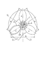
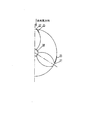
家屋建築群集風式及び広野構造群集風式風力中心発電所またはパワー・ステーションであって、建築群または構造群の中心部には、高層、または超高層の、全体の建物の階層の高さにわたっている中空円柱型の中心タワー・ビル28が設置され、タワー・ビル28のいずれの階層は、共に内径がDである中空の円柱体とそれと垂直する上下階層床7によって構成された羽根車ハウジング8を含み、中心タワー・ビル28の中心O点には、全体のタワー・ビル28の高さにわたっており、且つ地面中心軸線1と垂直し、及び中心軸線1と同軸し、且つ各層のタワー・ビル28を貫通する1つの集中伝動軸組合せ部材2を有し、それによって、各層のタワー・ビル28における羽根車の風力トルクを、集中伝動軸組合せ部材2の下端(または上端)に伝達してさらに増速装置、発電装置または動力伝動装置に伝達し、垂直軸式羽根車を使用する時に、各層のタワー・ビルにおける集中伝動軸組合せ部材2には、高さhがタワー・ビルの階層のネット高さHよりやや小さい、羽根数が2及び2以上である1つの羽根車3を設置し、水平軸式羽根車を使用する時に、タワー・ビル28の各層には、1つ及び1つ以上の水平軸式羽根車部材が設置され、該部材の羽根車軸21の前端に設置される羽根22の層数が1層及び1層以上であり、羽根車軸21の後端は、円錐状ギア19によって集中伝動軸2における円錐状ギア20と噛合し、建築群集風式風力中心発電所、パワー・ステーションとして、中心タワー・ビル28の中心O点を原点とし、径方向に2棟及び2棟以上のサブ建築を設置することによって、2ビラ及び複数ビラ建築群を構成し、その外壁が中心タワー・ビル28の外壁と連結され、且つ床29、天井蓋13、天井蓋支持ビームフレーム14と増速型風洞を形成し、広野構造群集風式風力中心発電所、パワー・ステーションとして、中心タワー・ビル28の中心O点を原点とし、径方向に伸出して2つまたは2つ以上の構造タワーを設置し、構造タワーの2つの側面がともに保護板31によってカバーされて中心タワー・ビル28と連結され、且つ床29、天井蓋13、天井蓋支持ビームフレーム14と増速型風洞を形成し、前記2種類の集風式風力中心発電所、パワー・ステーションの各層の中心タワー・ビル28は、2つのサブ建築物または2つの構造タワーの交差箇所の各層の中心タワー・ビル28の中空円柱体において、1つの吸込ダンパ6が開設され、それぞれ建築群集風式風力中心発電所、またはパワー・ステーション及び広野構造集風式風力中心発電所、パワー・ステーションを構成することを特徴とする。
House building community wind type and Hirono structure group wind type wind power center or power station, in the center of the building group or structure group, over the height of the entire building hierarchy, high-rise or super-high A hollow cylindrical
天井蓋支持ビームフレーム14の構造は、多相(2つのサブ建築間の外壁空間または2つの広野構造群ビームフレームの外壁空間が1相である)固定式と、O軸線1を回って、自然風の風来る方向に向いて回転でき、且つ上部円状レール33及び支持ビームフレーム34に支持される単相回転可能式と、を含み、その駆動方式は、中心軸駆動式及び走行車輪26による単独電動減速装置駆動式を含む。
The structure of the ceiling lid
集中伝動軸2に設置される増速装置、または発電装置の配置方式は、一台及び一台以上の直列接続、並列接続、直列接続兼並列接続を含み、前記増速装置、発電装置、動力駆動装置の設置場所は、集中伝動軸の下端と、上端を含む。
The speed increasing device installed on the
回転型天井蓋13を使用するときに、いずれの集風式中心発電所、パワー・ステーションは、単相のみを取り付けて、且つそれを風来る方向に位置決めさせる。
When using the rotating
サブ建築の平面図の外形は、円弧流線状A、矩形B、階段矩形Cを含む。 The outline of the plan view of the sub-architecture includes an arc streamline A, a rectangle B, and a staircase rectangle C.
各層の中心タワー・ビル28に設けられており、発電装置を定速度させるための調整可能な吸込ダンパ6の開閉方式は、手工式、単層自動開閉式、全体棟連動開閉式を含む。
The opening / closing method of the adjustable suction damper 6 provided in the
水平軸式羽根車の羽根形状は、双羽根式、多羽根式、上風向式、下風向式、セイルウィング式を含み、垂直軸式羽根車の型は、S型、プレートフィン・シェルター式、カップ状、Φ型、Δ型、プレートフィン直羽根式、ウォーム・ギア型、SとΦの組合せ型を含み、水平軸式羽根車ハウジング24は、走行車輪26によって、階層床7に固定される環状軌道に支持される。
The blade shape of the horizontal shaft type impeller includes a double blade type, a multi blade type, an upwind direction type, a downwind direction type, and a sail wing type, and the vertical axis type impeller type is S type, plate fin shelter type, Including cup type, Φ type, Δ type, plate fin direct blade type, worm gear type, combined type of S and Φ, the horizontal axis
増速装置11のフォームは、平行軸、同軸NGW型、同軸少歯相違型を含み、発電装置16のフォームは、縦式、横式を含み、円錐状ギア19、20の歯状は、伸開線、円弧、螺旋型を含み、増速装置11の歯状は、伸開線、円弧、少歯相違型を含み、発電装置のフォームは、同軸型、平行軸型を含む。
The form of the
集中伝動軸2の上下端によって設置される動力駆動負荷は、連動ポンプ、農業深加工機械、工業性加工機械のギア、ベルト車、チェーンホイール伝動システム、熱ポンプシステム装置を含む。
The power drive load installed by the upper and lower ends of the
発電機の出力は、建築物または構造物の自家用とし、系統連系で電力を提供し、また建築物自体に必要な熱供給システムの送配電装置及び発電所、パワー・ステーションを提供する。 The output of the generator is for private use of the building or structure, provides power through grid connection, and provides the power transmission / distribution device, power plant, and power station of the heat supply system necessary for the building itself.
本発明において、タワー・ビルに進入する風速を調整するための、吸込ダンパ6の面積の周方向における調整可能性、及び天井蓋13の径方向及び周方向における被覆面の調整可能性(比較的大きな自然風元式は一部または全部卸下搭載する)を有し、発電装置を定速度に回転させる装置が採用される。 In the present invention, it is possible to adjust the area of the suction damper 6 in the circumferential direction and adjust the covering surface in the radial direction and circumferential direction of the ceiling lid 13 (relatively) to adjust the wind speed entering the tower building. A large natural wind-source type is partly or wholly mounted wholesale), and a device that rotates the power generator at a constant speed is employed.
各棟の構造タワーの平面図の外形は、台形、等辺三角形、等辺内外円弧形であってもよく、天井蓋13、保護板31の材料は剛性体であってもよく、可撓性体であってもよく、材質が透明体、不透明体であってもよい。
The outline of the plan view of the structural tower of each building may be a trapezoid, an equilateral triangle, an equilateral inner and outer arc shape, and the material of the
〔発明の原理〕
周知のように、単位時間内に羽根の断面Fから流れ通過するパワーWは風速Vの3乗と正比例し、即ちρFV3(式中ρが空気密度である)、従来の伝統的な風力発電装置には共に自然風速が使用されるが、本発明は前記公式の原理を使用して、自然風速を、建築群外壁または構造ビームフレームの外縁保護板31、天井蓋13、増速風洞床29から経由させて全体の増速空間に形成させ、自然風は増速型風洞の入口面及びその弦長36を経由して中心タワー・ビルの風進入扉6に向けて流れて行く時に速度が絶えずに増大され、例えば増速型風洞の入口面弦長36の長さが100mで、中心タワー・ビルの風進入扉6の弦長が10mであれば、風速の増速比は100:10であり、即ち10倍も増加し(局所抵抗を見落として計算しない)、もし自然風速が5 m/secであれば、中心タワー・ビルの羽根車の羽根に作用できる風速が50 m/secで、同様な羽根面積の自然風と比べるとそのパワーが103=1000倍も増加した。本発明は、風洞出口面積の周方向における調整可能性、及び天井蓋13の径方向及び周方向における被覆面の調整可能性(比較的大きな自然風元式は一部または全部卸下搭載する)を利用して、タワー・ビルに進入する風速を調整し、発電装置を定速度に回転させる。
[Principle of the Invention]
As is well known, the power W flowing through the blade cross-section F within a unit time is directly proportional to the cube of the wind speed V, that is, ρFV3 (where ρ is the air density), a conventional traditional wind power generator. In the present invention, the natural wind speed is used, but the present invention uses the above-mentioned principle to convert the natural wind speed from the outer
1.従来の伝統的な風エネルギーの資源範囲を拡大した。本発明の増速効果によって、従来に採用された6〜8 m/sec風源を約3m/secに低減し、広大な地区を有用な風源にすることができる。
2.自然風発電装置の回転速度の調整不可性を、調整可能な定速度風力発電機に転換させることができる。
3.定速度ファンを創造するため、系統連系に対して有力な条件を創造し、従来の風力発電の系統連系の困難を克服した。
4.ユーザの距離を短縮し、出力設備のコストを大幅に下げた。
5.本発明の建築物内の居住、事務、工・商業及び周辺建築物に対して電源、熱源、低熱源、動力源を直接提供できる。
6.ターボ回転速度を、従来の伝統的な自然ファンの30r.p.mから200〜300r.p.mに向上しため、伝動モーメントを5〜10倍に低減し、伝動装置のコストを5〜10倍に低減させ、且つ大型風力ステーションの伝動装置の加工の難しさを大幅に低減した。
7.集中伝動を採用するため、用地面積及び管理費用を大幅に節約した。
8.1つの機械セットを、従来の約2千KWから2万KW、ひいては5〜10万KW/座に向上させた。
9.本発明を石油、石炭、天然ガスの使いきれた後の代替品にすることを可能にする。
1. Expanded the traditional traditional wind energy resource range. By the speed increasing effect of the present invention, the 6 to 8 m / sec wind source that has been conventionally employed can be reduced to about 3 m / sec, and a vast area can be made a useful wind source.
2. The inability to adjust the rotational speed of the natural wind power generator can be converted into an adjustable constant speed wind power generator.
3. In order to create a constant speed fan, we created a powerful condition for grid connection and overcame the difficulties of conventional wind power grid connection.
4). The distance of the user was shortened, and the cost of the output equipment was greatly reduced.
5. A power source, a heat source, a low heat source, and a power source can be directly provided to the residence, office work, engineering / commercial and surrounding buildings in the building of the present invention.
6). The turbo rotation speed was adjusted to 30r. p. m to 200-300 r. p. Therefore, the transmission moment was reduced 5 to 10 times, the cost of the transmission device was reduced 5 to 10 times, and the difficulty of processing the transmission device of the large wind station was greatly reduced.
7). Employing centralized transmission has saved significant land area and management costs.
8. One machine set was improved from the conventional about 2,000 KW to 20,000 KW, and eventually 50,000 to 100,000 KW / seat.
9. It makes it possible to make the present invention a substitute for exhausted oil, coal and natural gas.
2007年の北京の電気供給を例にし、人毎に平均0.84kWの電気供給容量として計算し(北京2007年11月30日放送局の報道によると、総電気供給容量が837万kWで、1000万人で計算すれば、1人当たりの平均が0.84kW容量になる)、且つ1人当たりの平均建築が20m2であることに基づいて計算すれば、60000 m2の発電所家屋建築は約3000人に提供できる一方、自己供給容量が3000×0.84=2520kWであれば十分であり、その他残り分は外へ供給でき、20000kW、毎年6000時間正常回転として計算すれば、一年の発電量が1.2億kW・Hで、0.5元/kW・Hで計算すれば一年の総利益が約6000万元である。一方、1台の広野式風力発電所、その自然風速が8m/sec、増速比が9であれば、その出口の速度が約70 m/secで、回転子の直径が16m、1層の高さが4mであるときに、1層当たりのパワーが約5000kWにも達することができ、30層で計算すれば(総有効高度が120mである)、その総導入容量が15万kWにも達することができるため、本発明(これからの10〜20年内)は家屋建築群に対して、その出口風速は50が適で、広野式風力発電所にとって、出口風速は70m/secが適であり、これは列車の速度向上と同じように、技術進歩に伴って、その速度がさらに向上できる。 Taking the electricity supply in Beijing in 2007 as an example, it was calculated as an average electricity supply capacity of 0.84 kW per person (according to a report by the Beijing Broadcasting Station on November 30, 2007, the total electricity supply capacity was 8.37 million kW, be calculated at 10 million, per capita average is 0.84kW volume), if and per average architecture calculated based on a 20 m 2, plant houses Architecture 60000 m 2 is about While it can be provided to 3000 people, if the self-supplied capacity is 3000 × 0.84 = 2520kW, it is enough, and the rest can be supplied to the outside, and if it is calculated as 20000kW, 6000 hours normal rotation every year, If the amount is 120 million kW · H and calculated at 0.5 yuan / kW · H, the annual total profit is about 60 million yuan. On the other hand, if one Hirono-type wind power plant has a natural wind speed of 8 m / sec and a speed increase ratio of 9, the exit speed is about 70 m / sec, the rotor diameter is 16 m, When the height is 4 m, the power per layer can reach about 5000 kW, and if calculated with 30 layers (total effective altitude is 120 m), the total installed capacity is as high as 150,000 kW In the present invention (within the next 10 to 20 years), an exit wind speed of 50 is suitable for a house building group, and an exit wind speed of 70 m / sec is suitable for a Hirono wind power plant. This, like the train speed increase, can be further improved with technological progress.
本発明は従来の建築設計規範をそんなに多くに打破する必要がない前提下で、家屋建築群式風力発電所の風速を、3m/sec軽風から50m/secに増速でき(増速比が16、内陸型)、一方、広野型集風発電所は和風クラス(8 m/sec)の自然風源を選択して70 m/sec風速に増速でき、ファンの発電パワーが風速の3乗と正比例(前記同、P.178)するため、従来の3枚羽根車水平軸羽根車自然風速発電所(理想の自然風速が清風クラス8〜10m/sec、一年の約20%の確率を占める)と比べ、同様な10m/sec自然風を例にして、本発明の羽根当たりの風向き面積の発電パワーがそれぞれ125倍及び343倍増加し、タワー・ビルの高度がほぼ同等(約100m)であるときに、本発明は羽根の直径が18mであるときに、約800m2の風向き面積を得られるが、従来の技術の2000kW装置は、羽根の直径が60mで、約100 m2の風向き面積しか得られないため、本発明の家屋建築群風力発電所装置は1〜5kWが適切で、広野式中心装置は最も多くときに5〜15万kWにも達することができる。 The present invention is capable of increasing the wind speed of a house building group wind power plant from 3 m / sec light wind to 50 m / sec under the assumption that it is not necessary to break the conventional architectural design norm so much (speed ratio is 16). On the other hand, the Hirono-type wind power plant can select a natural wind source of the Japanese class (8 m / sec) and increase the wind speed to 70 m / sec. Because it is in direct proportion (p. 178), the conventional three-blade horizontal axis impeller natural wind speed power plant (ideal natural wind speed is 8 to 10 m / sec in the clear wind class and occupies a probability of about 20% per year. ), The power generation area of the wind direction per blade of the present invention is increased by 125 times and 343 times, respectively, and the altitude of the tower building is almost the same (about 100 m). In some cases, the present invention has a blade diameter When a 8m, is obtained a wind area of about 800 m 2, the 2000kW devices of the prior art, since the diameter of the blade is at 60 m, obtained only wind area of about 100 m 2, house building of the present invention 1-5 kW is appropriate for group wind power plant equipment, and Hirono-type central equipment can reach 5 to 150,000 kW at most.
本発明の家屋建築群風力発電所の天井蓋13及び広野式風力発電所の天井蓋13は、局所径方向または周方向開き式構造を採用し、卸下搭載の目的を達するように、単独伝動システムによって鋼線を介して開閉を行うことができ、且つファンの速度を開閉または調整するように、台形立体空間の出入り扉6を閉鎖または調整してもよい。
The
本発明は必要であるときに、天井蓋13を局所に開けることによって卸下搭載することができ、この卸下搭載する動作は、手工的、単独機械的、集中機械的方式を含み、その伝動方式は、電動減速装置による直接伝動、チェーンホイール、鋼線介しての電動減速装置の伝動方式を含み、自然風の風来る方向が建築物または構造タワーの径方向中心軸線と平行する時に、建築物及び鉄塔の平面図の最も外の各の先端において、位置規制装置の風引き受け羽根25が配置され、前記風引き受け羽根25は、1つの縦軸が床から天井蓋13まで間の縦軸と、相応する折たたみ翼と、によって構成され、通常のとき、折たたみ翼が側壁面に密着され、前記風方向を遇う時に、折たたみ翼が風を引き受けるように1つの角度を伸びだして、且つ位置規制装置(例えばラチェットホイール)によって位置決められ、前記折たたみ翼及び縦軸を駆動する方式は、鋼線伝動、電機減速装置単独伝動、圧縮空気伝動、油圧伝動を含む。
When necessary, the present invention can be mounted in a wholesale manner by locally opening the
以下、図面に合わせて本発明を実施する最適な手段を詳細に説明する。家屋建築群集風式中心発電所のサブ建築及び広野構造式集風中心発電所の星状風引き鉄フレームは、共に、3つの相互に約120°になっている平面配置が好ましい。各地の風方向が梅花である特徴に基づいて、前記建築及び装置の方向位置決めは、最大な風引き効果を得るように、なるべく主導風方向を、ある1つのサブ建築またはある1つの遊星鉄フレームの中心線と平行させるべきであり、各地は本地区の基本風圧に基づいて本発明の建築物及び構築物の風速増速比を確定するべきで、最近の20年内に、家屋建築群式集風式風力発電所の羽根車の入口風速は50m/secが好ましく、導入容量は約2〜5万kWが好ましく、広野式集風発電所の羽根車の入口風速は70m/secが好ましく、導入容量は約5〜15万kW/所ごとが好ましい。技術の進歩及び時間の推移に伴って、前記入口風速はさらに非常に大きな価値増加余裕を有し、家屋建築群式集風式発電所は大中都市において6層及び30〜40層間が好ましく、垂直軸式羽根車はS型が最も簡単で、水平軸式羽根車は2層多羽根が好ましく、5万kW以上広野式風力発電所はブースター・ステーションを設置することが好ましく、その鉄塔は送配電鉄塔として兼用することが好ましい。本発電所は有効な落雷防護装置、安全高空走行保護レバー及び有効な防音装置を設置すべきで、本発明の家屋は、風吸込み風洞の増速効果を増加するように、高速風に近づくエリアに密閉式外壁を採用すべきである。本発明の実施は、構造面において本発明の特徴を有する以外に、建築面において各種の健康且つ美しい芸術造形を包容できるため、中国の文化特色及び現代化内包を有する風力中心発電所または風力中心パワー・ステーション及び家屋建築群を建築した。 The best means for carrying out the present invention will be described below in detail with reference to the drawings. The sub-architecture of the house building group wind-collecting central power plant and the star-shaped wind-drawn iron frame of the Hirono structural wind collecting central power plant are preferably arranged in three planes that are approximately 120 ° from each other. Based on the feature that the wind direction of each place is plum blossoms, the direction positioning of the building and the device should be set as the leading wind direction as much as possible in order to obtain the maximum wind pulling effect, one sub-building or one planetary iron frame The wind speed increase ratio of the buildings and structures according to the present invention should be determined based on the basic wind pressure of the Area. The wind speed at the inlet of the impeller of the wind power plant is preferably 50 m / sec, the introduction capacity is preferably about 2 to 50,000 kW, the inlet wind speed of the impeller at the Hirono wind power plant is preferably 70 m / sec, and the installed capacity Is preferably about 5 to 150,000 kW / place. With the progress of technology and the transition of time, the inlet wind speed has a much larger value increase margin, and the house building group wind collecting power plant preferably has 6 layers and 30-40 layers in large and middle cities, The vertical shaft impeller is the simplest of the S type, the horizontal shaft impeller is preferably a two-layer multi-blade, and a Hirono wind power plant with a capacity of 50,000 kW or more is preferably provided with a booster station, and its tower is It is preferable to double as a distribution tower. This power plant should be equipped with an effective lightning protection device, safe high altitude travel protection lever and effective soundproofing device, and the house of the present invention is an area approaching high speed wind so as to increase the speed increasing effect of the wind suction wind tunnel. A sealed outer wall should be used. The implementation of the present invention, in addition to having the features of the present invention in terms of structure, can encompass various healthy and beautiful art forms in the architectural aspect, so that the wind-center power plant or wind-center power with Chinese cultural features and modernization inclusion・ Building stations and houses.
1、中心軸線
2、集中伝動軸
3、羽根車
4、軸受
5、軸受ホルダー
6、吸込ダンパ
7、階層床
8、羽根車ハウジング
9、軸継ぎ手
10、人用昇降エレベータ
11、他電源式縦式モータ
12、減速、鋼線ローラ装置
13、天井蓋
14、天井ビームフレーム
15、増速装置
16、発電装置
17、高圧線カンチレバー架設装置
18、自然風方向指示信号装置
19、アングル歯車
20、アングル歯車
21、水平式羽根車軸
22、羽根
23、タワー・ビル床7における環状レール
24、水平式羽根車ハウジング
25、風引き受け羽根
26、自由走行車輪、またはモータ及び減速装置付き駆動走行車輪
27、ヒンジピン
28、中心タワー・ビル
29、増速風洞床
30、風引き鉄塔鋼構造ビームフレーム
31、保護板
32、補助支持ビームフレーム
33、上部円形レール
34、上部円形レールの下部に設置される支持ビームフレーム
35、地面円形レール
36、増速型風洞入口面及び弦長
1,
Claims (11)
吸込ダンパ(6)の面積を周方向において調整することにより、または、天井蓋(13)の被覆面を径方向及び周方向において調整することにより、タワー・ビルに進入する風速を調整して、発電装置を定速度に回転させる装置、をさらに有する、
ことを特徴とする家屋建築群集風式及び広野構造群集風式風力中心発電所またはパワー・ステーション。 In a house building group (hereinafter abbreviated as building group) wind-collecting type and Hirono structure group (hereinafter abbreviated as structure group) wind-collecting wind power plant or power station, Is a hollow column-shaped central tower building (28), which is a high-rise or super-high building that spans the height of the entire building hierarchy. And the impeller housing (8) constituted by the upper and lower floors (7) perpendicular to the hollow cylindrical body, and the central tower building (28) has a central O-point at the center O point (28). ), And is perpendicular to the ground center axis (1) and coaxial with the center axis (1) and passes through the tower building (28) of each layer (1). And thereby The wind power torque of the impeller in the tower building (28) of the layer is transmitted to the lower end (or upper end) of the concentrated transmission shaft combination member (2) and further transmitted to the speed increasing device, the power generation device or the power transmission device, and the vertical When using the shaft type impeller, the concentrated transmission shaft combination member (2) in the tower building of each layer has a height h slightly smaller than the net height H of the tower building hierarchy, and the number of blades is 2 and 2. When one impeller (3) is installed and the horizontal axis impeller is used, one and one or more horizontal axis impeller members are installed in each layer of the tower building (28). The number of layers of the blade (22) installed at the front end of the impeller shaft (21) of the member is one layer or more, and the rear end of the impeller shaft (21) is formed by a conical gear (19). Engage with the conical gear (20) on the central transmission shaft (2) By installing two buildings and two or more sub-buildings in the radial direction from the center O point of the central tower building (28) as a wind-collecting wind power plant and power station, two villas and multiple It constitutes a villa building group, its outer wall is connected to the outer wall of the central tower building (28), and forms a speed increasing wind tunnel with the floor (29), ceiling lid (13), ceiling lid support beam frame (14) As a Hirono structure group wind-type wind power plant and power station, the center O point of the central tower building (28) is the origin, and two or more structural towers are installed extending in the radial direction. The two sides of the structural tower are both covered by a protective plate (31) and connected to the central tower building (28), and the floor (29), the ceiling lid (13), the ceiling lid support beam frame (14), Speed-up wind tunnel The central tower building (28) of each layer of the two types of wind-collecting wind power plant, power station is the central tower building of each layer at the intersection of two sub-buildings or two structural towers In the hollow cylindrical body of (28), one suction damper (6) is established, and each constitutes a building group wind-collected wind power plant, or power station and Hirono structure wind-powered wind power plant, power station And
By adjusting the area of the suction damper (6) in the circumferential direction, or by adjusting the covering surface of the ceiling lid (13) in the radial direction and the circumferential direction, the wind speed entering the tower building is adjusted, A device for rotating the power generation device at a constant speed;
House building community wind type and Hirono structure group wind type wind power plant or power station characterized by that.
The external shape of the plan view of the structural tower of each building may be trapezoidal, equilateral triangle, equilateral inner and outer arc shape, and the material of the ceiling lid (13) and the protective plate (31) may be a rigid body, The power plant or power station according to claim 1, wherein the power plant or power station may be a flexible body, and may be a transparent body or an opaque body.
Applications Claiming Priority (2)
| Application Number | Priority Date | Filing Date | Title |
|---|---|---|---|
| CN201110259162.3A CN102979675B (en) | 2011-09-05 | 2011-09-05 | Wind-collecting type housing building group and open-field structure group wind junction generating station and power station |
| CN201110259162.3 | 2011-09-05 |
Publications (2)
| Publication Number | Publication Date |
|---|---|
| JP2013053628A JP2013053628A (en) | 2013-03-21 |
| JP5542885B2 true JP5542885B2 (en) | 2014-07-09 |
Family
ID=47710865
Family Applications (1)
| Application Number | Title | Priority Date | Filing Date |
|---|---|---|---|
| JP2012194922A Active JP5542885B2 (en) | 2011-09-05 | 2012-09-05 | House building community wind type and Hirono structure group wind type wind power center or power station |
Country Status (4)
| Country | Link |
|---|---|
| US (1) | US9657712B2 (en) |
| JP (1) | JP5542885B2 (en) |
| CN (1) | CN102979675B (en) |
| DE (1) | DE102012017521B4 (en) |
Families Citing this family (4)
| Publication number | Priority date | Publication date | Assignee | Title |
|---|---|---|---|---|
| CN104264884A (en) * | 2014-08-20 | 2015-01-07 | 中亿丰建设集团股份有限公司 | Office building atrium roof and mounting method thereof |
| CN105257482A (en) * | 2015-08-10 | 2016-01-20 | 方祖彭 | Power station of wind collecting type wind power hub power generation station |
| US11022094B2 (en) | 2017-05-24 | 2021-06-01 | General Electric Company | Modular blade structure and method of assembly |
| CN107288821B (en) * | 2017-06-30 | 2024-04-26 | 崔国学 | Novel skyscraper integrating wind power generation |
Family Cites Families (35)
| Publication number | Priority date | Publication date | Assignee | Title |
|---|---|---|---|---|
| US1112203A (en) * | 1913-04-01 | 1914-09-29 | Albert J Fandrey | Atmospheric power-generator. |
| JPS5194042A (en) * | 1975-02-10 | 1976-08-18 | ||
| US4134710A (en) * | 1977-03-28 | 1979-01-16 | Atherton Dewitt T | Simultaneous plural-directional flow motor |
| JPS57202756U (en) * | 1981-06-19 | 1982-12-23 | ||
| US4551631A (en) * | 1984-07-06 | 1985-11-05 | Trigilio Gaetano T | Wind and solar electric generating plant |
| JP3270906B2 (en) * | 1993-03-04 | 2002-04-02 | 清人 古屋 | Wind power generator |
| WO1995019501A1 (en) * | 1994-01-12 | 1995-07-20 | Hirano, Akinori | Atmospheric pressure power generation apparatus |
| DE19648632A1 (en) * | 1996-10-17 | 1998-04-23 | Burger Helmut | Wind power system for converting wind energy into electric energy in horizontal and vertical arrangement |
| US6041596A (en) * | 1998-03-23 | 2000-03-28 | Royer; George R. | Building structure for utilization of wind power |
| DE19920560A1 (en) * | 1999-05-05 | 1999-08-26 | Themel | Wind power plant with vertical rotor |
| CA2290196A1 (en) * | 1999-09-29 | 2001-03-29 | Denis Guay | Steerable fluid current powered turbine |
| DE10059504A1 (en) * | 2000-11-30 | 2003-08-28 | Frank Jendrusch | Extreme multistory building as power generation system, uses wind from heated building wall as drive medium for devices for converting into electrical energy, e.g. interior wind wheels |
| JP3716334B2 (en) * | 2001-06-07 | 2005-11-16 | 村井 和三郎 | Wind pumping power generation equipment |
| US6749393B2 (en) * | 2001-08-13 | 2004-06-15 | Yevgeniya Sosonkina | Wind power plant |
| IL152518A0 (en) * | 2002-10-28 | 2003-05-29 | Gabriel Raziel | A method for channeling wind to produce electricity |
| WO2004099605A2 (en) * | 2003-04-30 | 2004-11-18 | Taylor Ronald J | Wind turbine having airfoils for blocking and directing wind and rotors with or without a central gap |
| GB2402976B (en) * | 2003-06-05 | 2006-09-27 | Intec Power Systems Ltd | Generator |
| US7172386B2 (en) * | 2004-08-05 | 2007-02-06 | Minh-Hoang Dinh Truong | Wind and solar power plant with variable high speed rotor trains |
| JP5075335B2 (en) * | 2004-11-19 | 2012-11-21 | 良治 渡部 | Wind power generator |
| DE102005060818A1 (en) * | 2005-03-15 | 2006-09-21 | Kelaiditis, Konstantin, Dr.-Ing. | Method and device for using wind energy |
| DE102006057677A1 (en) * | 2006-04-13 | 2007-10-18 | Konstantin Dr.-Ing. Kelaiditis | Device for the use of flow energy |
| RO122739B1 (en) * | 2006-09-28 | 2009-12-30 | Corneliu Gheorghe Boţan | Collector concentrator for wind power station and wind network using the same |
| KR100810990B1 (en) * | 2006-10-18 | 2008-03-11 | 주식회사 에어로네트 | Power generation system having vertical wind turbine of jet-wheel type for wind power |
| WO2008075422A1 (en) * | 2006-12-20 | 2008-06-26 | Hashimoto, Yoshimasa | Wind-driven generator |
| AU2007351043B2 (en) * | 2007-04-16 | 2012-08-16 | Qingwan Lin | A wind energy power machine, a wind energy power system and a wind energy generating system |
| US8072091B2 (en) * | 2007-04-18 | 2011-12-06 | Samuel B. Wilson, III | Methods, systems, and devices for energy generation |
| US8801359B2 (en) * | 2007-05-05 | 2014-08-12 | Gordon David Sherrer | System and method for extracting power from fluid using a Tesla-type bladeless turbine |
| HUP0700705A2 (en) * | 2007-10-30 | 2009-10-28 | Viktor Dr Gyoergyi | Vertical axis wind turbine and power station |
| CN101469674A (en) * | 2007-12-26 | 2009-07-01 | 程新生 | Wind energy mansion with wind accumulating roof, wind accumulating door, wind draining door and wind power generator |
| WO2009152306A1 (en) * | 2008-06-13 | 2009-12-17 | The Timken Company | Epicyclic gear system with flexpins and helical gearing |
| US7821153B2 (en) * | 2009-02-09 | 2010-10-26 | Grayhawke Applied Technologies | System and method for generating electricity |
| US8651798B2 (en) * | 2009-02-12 | 2014-02-18 | Sheer Wind, Inc. | Kinetic hydropower generation system and intake therefore |
| US8878382B2 (en) * | 2009-04-20 | 2014-11-04 | Carmelito B. Tianchon | Power generation system or turbine with potential energy gain |
| JP3153015U (en) * | 2009-06-10 | 2009-08-20 | 正晴 岡田 | Wind power generation system |
| US8210792B2 (en) * | 2009-06-19 | 2012-07-03 | University Of Miami | Wind energy system |
-
2011
- 2011-09-05 CN CN201110259162.3A patent/CN102979675B/en active Active
-
2012
- 2012-09-04 DE DE102012017521.3A patent/DE102012017521B4/en active Active
- 2012-09-05 US US13/603,446 patent/US9657712B2/en active Active
- 2012-09-05 JP JP2012194922A patent/JP5542885B2/en active Active
Also Published As
| Publication number | Publication date |
|---|---|
| CN102979675A (en) | 2013-03-20 |
| CN102979675B (en) | 2015-03-18 |
| JP2013053628A (en) | 2013-03-21 |
| DE102012017521B4 (en) | 2014-12-18 |
| DE102012017521A1 (en) | 2013-03-07 |
| US20130058759A1 (en) | 2013-03-07 |
| US9657712B2 (en) | 2017-05-23 |
Similar Documents
| Publication | Publication Date | Title |
|---|---|---|
| CN103807107B (en) | Two-wayly carry the multiple blade fluid energy collecting multicomputer wind motor for electric generation of Y-shaped to turning a circle rail bearing | |
| JP5542885B2 (en) | House building community wind type and Hirono structure group wind type wind power center or power station | |
| CN101550904A (en) | Shaftless vertical axis wind turbine | |
| CN108431402B (en) | Vertical axis wind turbine with shielding blade supporting piece | |
| WO2011134372A1 (en) | Wind wheel device for wind gathering and wind power generation device | |
| CN102777062B (en) | Self-starting funneling wind concentration wind power generation system | |
| CN202348583U (en) | Multiple-winding variable-pole-speed impeller vertical wind power generation system | |
| CN101539108A (en) | Double electric motor press-gathered wind power generating device | |
| CN1730934A (en) | Vane speed regulator for electricity generation by wind power and ocean current | |
| CN103925163A (en) | Hydraulic and pneumatic one-way shaft and birotor type power generating device | |
| CN101749179B (en) | Rectification speed increasing tower used for vertical axis wind turbine | |
| US20200318608A1 (en) | Wind Turbine | |
| CN103629050B (en) | Pass through eddy flow aerogenerator | |
| CN101105081A (en) | Wind energy edifice | |
| CN103956964B (en) | A kind of tower around distribution wind-light complementing power generation device | |
| CN102410145B (en) | Multi-winding variable-pole variable-speed vane-type vertical wind power generating system | |
| CN101046190A (en) | Wind driven generator combination | |
| CN101225802A (en) | Flying wind power generator, units | |
| CN102168655A (en) | Resistance difference type synchronous linkage integrated wind wave and light heat electromechanical energy conversion system | |
| CN106351794A (en) | High-altitude wind energy comprehensive utilization engineering concept | |
| CN207761884U (en) | A kind of multi-functional tower system of multi-claw type for wind power generation | |
| CN201835983U (en) | Multi-layered sail for wind power generation | |
| EP3214303B1 (en) | Rotor vertical axis wind turbine | |
| CN101074650A (en) | Amplifying wind-driven high-altitude generator | |
| CN206110000U (en) | Wind energy utilization type subtracts a year sound barrier |
Legal Events
| Date | Code | Title | Description |
|---|---|---|---|
| A977 | Report on retrieval |
Free format text: JAPANESE INTERMEDIATE CODE: A971007 Effective date: 20130913 |
|
| A131 | Notification of reasons for refusal |
Free format text: JAPANESE INTERMEDIATE CODE: A131 Effective date: 20130924 |
|
| A601 | Written request for extension of time |
Free format text: JAPANESE INTERMEDIATE CODE: A601 Effective date: 20131205 |
|
| A602 | Written permission of extension of time |
Free format text: JAPANESE INTERMEDIATE CODE: A602 Effective date: 20131210 |
|
| A521 | Request for written amendment filed |
Free format text: JAPANESE INTERMEDIATE CODE: A523 Effective date: 20140124 |
|
| TRDD | Decision of grant or rejection written | ||
| A01 | Written decision to grant a patent or to grant a registration (utility model) |
Free format text: JAPANESE INTERMEDIATE CODE: A01 Effective date: 20140430 |
|
| A61 | First payment of annual fees (during grant procedure) |
Free format text: JAPANESE INTERMEDIATE CODE: A61 Effective date: 20140507 |
|
| R150 | Certificate of patent or registration of utility model |
Ref document number: 5542885 Country of ref document: JP Free format text: JAPANESE INTERMEDIATE CODE: R150 |
|
| R250 | Receipt of annual fees |
Free format text: JAPANESE INTERMEDIATE CODE: R250 |
|
| R250 | Receipt of annual fees |
Free format text: JAPANESE INTERMEDIATE CODE: R250 |
|
| S111 | Request for change of ownership or part of ownership |
Free format text: JAPANESE INTERMEDIATE CODE: R313113 |
|
| R350 | Written notification of registration of transfer |
Free format text: JAPANESE INTERMEDIATE CODE: R350 |
|
| R250 | Receipt of annual fees |
Free format text: JAPANESE INTERMEDIATE CODE: R250 |
|
| R250 | Receipt of annual fees |
Free format text: JAPANESE INTERMEDIATE CODE: R250 |
|
| R250 | Receipt of annual fees |
Free format text: JAPANESE INTERMEDIATE CODE: R250 |
|
| R250 | Receipt of annual fees |
Free format text: JAPANESE INTERMEDIATE CODE: R250 |
|
| R250 | Receipt of annual fees |
Free format text: JAPANESE INTERMEDIATE CODE: R250 |
|
| R250 | Receipt of annual fees |
Free format text: JAPANESE INTERMEDIATE CODE: R250 |