JP5542614B2 - Flow measuring device - Google Patents
Flow measuring device Download PDFInfo
- Publication number
- JP5542614B2 JP5542614B2 JP2010240252A JP2010240252A JP5542614B2 JP 5542614 B2 JP5542614 B2 JP 5542614B2 JP 2010240252 A JP2010240252 A JP 2010240252A JP 2010240252 A JP2010240252 A JP 2010240252A JP 5542614 B2 JP5542614 B2 JP 5542614B2
- Authority
- JP
- Japan
- Prior art keywords
- flow
- flow rate
- rate measuring
- measuring device
- passage
- Prior art date
- Legal status (The legal status is an assumption and is not a legal conclusion. Google has not performed a legal analysis and makes no representation as to the accuracy of the status listed.)
- Expired - Fee Related
Links
Images


Landscapes
- Measuring Volume Flow (AREA)
Description
本発明は、流量計に係わり、特に自動車エンジンの吸気系を構成して、その吸気量を検出、さらには制御するのに適する流量測定装置に関する。 The present invention relates to a flow meter, and more particularly, to a flow rate measuring apparatus suitable for configuring an intake system of an automobile engine and detecting and controlling the intake air amount thereof.
空気流量を計測する流量測定装置として、発熱抵抗体を加熱制御し発熱抵抗体の放熱量によって流量を計測するものや、発熱抵抗体を加熱制御し発熱抵抗体の近傍に配置した感温抵抗体の温度変化によって流量を計測するものなどが知られている。 As a flow measurement device that measures the air flow rate, the heating resistor is controlled by heating and the flow rate is measured by the amount of heat released from the heating resistor, or the temperature sensitive resistor is placed near the heating resistor by controlling the heating resistor. A device that measures the flow rate according to the temperature change is known.
流量測定装置は、車両の吸気ダクトの一部に装着され、吸入空気流量を測定する役割を持つ。通常、吸気ダクト内にはエアフィルタが設けられており、吸気ダクト内に流入する空気に含まれるダストをエアフィルタで取り除いている。しかし、ダストの大きさによってはエアフィルタを通過してしまうものがあり、またエアフィルタ交換後の装着不具合によりダストが吸気ダクト内へ入り込んでしまったりすることがある。吸気ダクト内に入り込んだダストは、アクセルの踏み込み量が増加すると流体とともに数十m/sにまで加速され、流量測定装置の副通路内にまで到達することがある。副通路内に配置された流量計測素子には、非常に薄い部分があり、ダストが衝突することにより破壊される可能性が考えられる。また、吸気ダクト内に入り込んだダストが流量測定装置の流量計測素子に付着すると、流量計測素子の放熱特性が変化して出力特性変化を引き起こす可能性が考えられる。 The flow rate measuring device is attached to a part of the intake duct of the vehicle and has a role of measuring the intake air flow rate. Usually, an air filter is provided in the intake duct, and dust contained in the air flowing into the intake duct is removed by the air filter. However, depending on the size of the dust, some may pass through the air filter, and dust may enter the intake duct due to a mounting failure after replacing the air filter. The dust that has entered the intake duct is accelerated to several tens of m / s together with the fluid when the amount of depression of the accelerator is increased, and may reach the sub-passage of the flow rate measuring device. The flow rate measuring element arranged in the sub-passage has a very thin portion, and there is a possibility that the dust may be destroyed by colliding with dust. Further, if dust that has entered the intake duct adheres to the flow rate measuring element of the flow rate measuring device, the heat radiation characteristic of the flow rate measuring element may change to cause a change in output characteristic.
吸気ダクト内に進入したダストなどから流量計測素子を保護し、汚損による経時劣化を防止する構造として、流量検出部が下面側になるように、感熱抵抗体を流体の流れ方向に対して、20〜60度の角度を設けて配置した感熱式流量測定装置が知られている(特許文献1参照)。また、反センシング部分が上流を向くように、流路の軸方向に対して角度αだけ傾斜させて流量計測素子を装着した流量測定装置が知られている(特許文献2参照)。 As a structure that protects the flow rate measuring element from dust entering the intake duct and prevents deterioration over time due to contamination, the thermal resistor is placed in the direction of fluid flow so that the flow rate detection unit is on the lower surface side. A heat-sensitive flow rate measuring device arranged at an angle of ˜60 degrees is known (see Patent Document 1). Further, there is known a flow rate measuring device in which a flow rate measuring element is mounted while being inclined by an angle α with respect to the axial direction of the flow path so that the anti-sensing portion faces upstream (see Patent Document 2).
しかしながら、上述した技術は、流体の流れる速度が一定の定常流に対してはダストなどから流量計測素子を保護する効果はあるものの、脈動流のような流体の流れる速度が遅くなったり速くなったりする非定常な流れに対しては、ダストの運動方向が流体から受ける力によって変則的に変わりセンシング部分へダストが到達してしまうといった課題がある。 However, although the above-described technique has an effect of protecting the flow measuring element from dust or the like for a steady flow with a constant fluid flow speed, the flow speed of the fluid such as a pulsating flow becomes slow or fast. For the unsteady flow, there is a problem that the direction of movement of the dust changes irregularly depending on the force received from the fluid and the dust reaches the sensing portion.
そこで、本発明の目的は、脈動流のような非定常な流れ場においても耐ダスト性に優れ、特性誤差が生じにくく信頼性の高い流量測定装置を提供することにある。 SUMMARY OF THE INVENTION An object of the present invention is to provide a highly reliable flow rate measuring device that is excellent in dust resistance even in an unsteady flow field such as a pulsating flow, is less likely to cause a characteristic error.
上記目的を達成するために、本発明の流量測定装置は、流体が流れる主通路内に配置され前記流体の一部を取り込む副通路と、前記副通路内に配置され発熱抵抗体パターンが形成された流量計測素子と、前記流量計測素子が搭載される支持体と、を有し、前記流量計測素子が搭載される面と前記副通路の通路形成面とで構成される第一の流体通路部と、前記流量計測素子が搭載される面とは反対側の面と前記副通路の通路形成面とで構成される第二の流体通路部と、を備えた流量測定装置において、前記流量計測素子に対して前記流体の流れの上流側に対向する前記第一の流体通路部の前記通路形成面は、前記流体の流れを前記流量計測素子へ向けるような傾斜面を有し、前記傾斜面は、異なる向きの二面以上の面から構成されている。 In order to achieve the above object, a flow rate measuring device according to the present invention includes a sub-passage that is disposed in a main passage through which a fluid flows and takes a part of the fluid, and a heating resistor pattern that is disposed in the sub-passage. A first fluid passage section comprising a surface on which the flow rate measuring element is mounted and a passage forming surface of the sub-passage. And a second fluid passage portion comprising a surface opposite to the surface on which the flow rate measuring element is mounted and a passage forming surface of the sub-passage, wherein the flow rate measuring element The passage forming surface of the first fluid passage portion facing the upstream side of the fluid flow has an inclined surface that directs the fluid flow to the flow rate measuring element, and the inclined surface is It is composed of two or more surfaces with different orientations.
本発明によれば、ダストが発熱抵抗体パターン側流体通路部の発熱抵抗体のパターンよりも上流側の対向する面に設けた傾斜面で跳ね返されたのち、流体の流れに乗って発熱抵抗体のパターンに向かって流れるのを抑制することができる。そのため、発熱抵抗体パターンで構成される流体計測素子の破損あるいは汚損を抑制することができ、脈動流のような非定常な流れ場においても耐ダスト性に優れ、特性誤差が生じにくく信頼性の高い流量測定装置を提供できる。 According to the present invention, after the dust is rebounded by the inclined surface provided on the opposite surface upstream of the heating resistor pattern of the heating resistor pattern side fluid passage portion, the heating resistor rides on the fluid flow. The flow toward the pattern can be suppressed. For this reason, it is possible to suppress damage or contamination of the fluid measuring element composed of the heating resistor pattern, and it is excellent in dust resistance even in an unsteady flow field such as pulsating flow, and it is difficult to cause characteristic errors and is reliable. A high flow measuring device can be provided.
本発明に係る以下の実施例は、自動車用の内燃機関に吸入される空気流量を測定するために用いられる流量測定装置に係り、吸入される空気に混じって吸気ダクト内を流れるダストなどの異物によって流量計測素子が破損することを防止し、また安定した流量測定を行えるような構造を提供するものである。以下の説明では、ダストなどの異物を単にダストと呼んで説明する。 The following embodiments of the present invention relate to a flow rate measuring device used for measuring the flow rate of air sucked into an internal combustion engine for automobiles, and foreign matters such as dust flowing in the intake duct mixed with the sucked air. Thus, it is possible to prevent the flow measuring element from being damaged by the above and provide a structure capable of performing stable flow measurement. In the following description, foreign substances such as dust are simply referred to as dust.
以下、本発明の実施例について説明する。 Examples of the present invention will be described below.
図1は本発明の一実施例の流量測定装置を示した図であり、具体的には、図1(a)は流量測定装置の正面図、図1(b)はそのA−A断面拡大図、図1(c)はB−B断面拡大図である。図1に従い本実施例の構成部品について説明する。 FIG. 1 is a view showing a flow rate measuring device according to an embodiment of the present invention. Specifically, FIG. 1 (a) is a front view of the flow rate measuring device, and FIG. FIG. 1C is an enlarged cross-sectional view taken along the line BB. The components of the present embodiment will be described with reference to FIG.
図1(a)に示すように、電子回路5と外部機器とを電気的に接続するためのコネクタターミナル1を有するコネクタ2と、流量測定装置を流体管路構成部材であるボディ15に固定するためのモジュール支持部3と、電子回路5を保持するハウジング枠体部4とがプラスチックモールドにて一体成型されている。コネクタターミナル1は電子回路5の端部に形成したボンディングパッド11とボンディングワイヤ12により電気的に接続されている。電子回路5は、平板状部材である基板上に回路素子を配置し、配線によって接続した回路基板として構成される。
As shown in FIG. 1A, a
また、ハウジング枠体部4には副通路8が形成されたバイパスモールド部7が結合されている。流量計測素子6は、電子回路5に搭載された状態で、副通路8内に配置される。ハウジング枠体部4及びバイパスモールド部7は、流体管路を構成するボディ15に開けた矩形の穴からボディ15内に挿入され、固定ネジ10によりボディ15に締めつけ固定される。これにより、吸気通路9を流れるエンジンへの吸入空気29の一部が副通路8へ分流する。その分流した吸入空気29の流量を流量計測素子6により検出してエンジンに吸入される空気の全流量を検出する。
Further, a
図1(b)に示すように、流量計測素子6は平板状部材である基板とこの基板上に薄膜形成プロセスにより形成された発熱抵抗体などの抵抗体のパターン6aとによって構成されている。流量計測素子6の基板面が電子回路5の基板面とほぼ平行になるように電子回路5に固定されている。電子回路5はハウジング枠体部4に内包され、副通路8内を流れる流体30の流れの方向に対して平行になるように固定される。尚、本実施例において、流体30は副通路8に取り込まれたボディを流れる吸入空気29である。
As shown in FIG. 1B, the flow
このとき、電子回路5における発熱抵抗体のパターンの設けられた面5aは、副通路8内の流体30の流れに沿うように配置され、電子回路5における発熱抵抗体パターン構成面5aと副通路8の通路形成面8dとの間には流体が流れる発熱抵抗体パターン側流体通路部8aが構成され、電子回路5における発熱抵抗体パターン構成面5aとは反対側の面5bと副通路8の通路形成面8cとの間には背面側流体通路部8bが構成される。すなわち、電子回路5の両面5a,5bに流体30が流れるように構成されている。
At this time, the
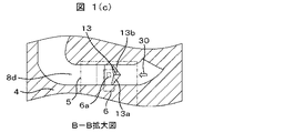
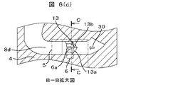
図1(c)に示すように、通路形成面8dには、抵抗体のパターン6aよりも上流側に、流体30を抵抗体のパターン6aの中心から外側へ誘導する誘導部として誘導面13a,13bが構成される。
As shown in FIG. 1C, on the
誘導面13a,13bは、流体30の流れを抵抗体のパターン6aへ向ける、異なる向きの二面の傾斜面であり、流体30の流れを抵抗体のパターン6aの中心にある稜線13から外側へ誘導するように構成されている。
The guide surfaces 13a and 13b are two inclined surfaces in different directions for directing the flow of the fluid 30 to the
すなわち、通路形成面8dは、誘導面13a,13bを構成する傾斜面を有している。傾斜面である誘導面13a,13bは、流体30を抵抗体のパターン6aの中心より外側へ流れるように傾斜している。
That is, the
このような構成により、流体30を抵抗体のパターン6aの中心より外側へ流すことができるため、流体30の流れに乗って吸入空気29に混じって吸気ダクト内を流れるダストなどの異物が発熱抵抗体のパターン6aに向かって流れるのを抑制することができ、発熱抵抗体パターン6aで構成される流体計測素子6の破損あるいは汚損を抑制することができる。
With such a configuration, since the fluid 30 can flow outside the center of the
なお、誘導面13a,13bが構成されている通路形成面8dとは反対側の背面側流体通路部8bの通路形成面8cは、絞り形状を有している。
The
ここで、図1に示した実施例の効果を確認するために、図2,図3を使って流量計測素子6へのダストなどの飛跡の形態を説明する。
Here, in order to confirm the effect of the embodiment shown in FIG. 1, the form of tracks such as dust on the flow
図2は、副通路8に吸入空気29の流れる速度が一定の定常流の場合、CAE解析による一定時間ごとのダスト14の飛跡を示す。時間T1では、副通路8内に進入してきたダスト14は、副通路8が曲がりを持つ構造であるため、慣性力により外周側へと向かう飛跡となる。時間T2では、ダスト14は、電子回路5の裏面を通り抜け、時間T3では、下流側へと流れていく。このように、定常流の場合、ダスト14が通り抜ける飛跡は一定であり、飛跡にかからないように電子回路5を配置することで、流量計測素子6へ向かうことなく、電子回路5の裏面を通り抜けていくことが確認できる。
FIG. 2 shows the tracks of the
ここで、電子回路5の裏面とは、電子回路5における発熱抵抗体パターン構成面5aとは反対側の面5bのことであって、背面(背面側)ということにする。これに対して、電子回路5における発熱抵抗体パターン構成面5aを、電子回路5の表面あるいは流量計測素子構成面(表面側)ということにする。また、電子回路5の上流側側面5cとは、電子回路5を構成する回路基板の厚さ方向に沿う面のうち、流体の流れ方向において、上流側に位置する面のことである。一方、下流側には下流側側面5dが存在する。
Here, the back surface of the
次に、本発明の一実施例の副通路8における場合の結果を図3に示す。図3は、通路形成面8dに設けた抵抗体のパターン6aよりも上流側の誘導面13a,13bを形成した副通路8を流れる吸入空気29の速度が遅くなったり速くなったりする非定常な流れの場合の、CAE解析による一定時間ごとのダスト14の飛跡を示す。
Next, the result in the case of the
図3に示すように、副通路8内に進入してきたダスト14は電子回路5に達するまでは、副通路8が曲がりを持つ構造であるため、慣性力により外周側へと向かう飛跡となる。しかし、電子回路5の流れに垂直である上流側側面5cに衝突したダスト14は、図3(a)時間T1では流れとは逆の方向へ大きく跳ね返され、図3(b)時間T2では逆に流れに押し戻されてダスト14の一部が、電子回路5の表面に向かう。さらに、図3(c)時間T3では、ダスト14の一部が、電子回路5の表面に向かうが、通路形成面8dに誘導部を設けたことで、誘導面13a,13bにダスト14が衝突し、抵抗体のパターン6aの中心から外側へ誘導されることが確認される。また、図3(d)に示すダストの飛跡より抵抗体のパターン6aの中心から外側へ誘導されることが確認される。このように、非定常な流れの場合、ダスト14が通り抜ける飛跡は不規則であるが、誘導面13a,13bを設けるだけで、流量計測素子6中心線上から遠ざかる方向へダストを導くことが可能となり、流量計測素子6への衝突を抑制することができる。
As shown in FIG. 3, the
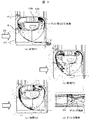
図4に第二の実施例を示す。図1に示した実施例に対し、図4(c)に示す誘導面16a,16b,16c,16dの誘導面の形状を、二面以上の面、あるいは平面で形成したもので、ダスト14が衝突したときに抵抗体のパターン6aの中心に向かって跳ね返るのを抑制する効果が期待できる。少なくても稜線の1本は、抵抗体のパターン6aの中心に形成されると効果的である。
FIG. 4 shows a second embodiment. In contrast to the embodiment shown in FIG. 1, the shape of the guide surfaces 16a, 16b, 16c, and 16d shown in FIG. It can be expected to suppress the rebounding toward the center of the
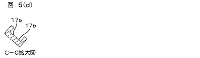
図5に第三の実施例を示す。図1に示した実施例に対し、図5(c)に示す誘導面17a,17bの誘導面の形状を、各々凹曲面で形成したもので、ダスト14が衝突したときに抵抗体のパターン6aの中心に向かって跳ね返るのを抑制する効果が期待できる。稜線は、抵抗体のパターン6aの中心に形成されると効果的である。
FIG. 5 shows a third embodiment. In contrast to the embodiment shown in FIG. 1, the guide surfaces 17a and 17b shown in FIG. 5C are formed with concave curved surfaces, and when the
図6に第四の実施例を示す。図1に示した実施例に対し、図6(d)に示す通路形成面18a,18b,18c,18dの誘導面に接合した抵抗体のパターン6aに平行向きに変える通路形成面の形状を、二面以上の面、あるいは平面で形成したもので、流体30の流れを抵抗体のパターン6aから離すことなく、ダスト14を中心から外側へ誘導する効果が期待できる。少なくても稜線の1本は、抵抗体のパターン6aの中心に形成されると効果的である。
FIG. 6 shows a fourth embodiment. In contrast to the embodiment shown in FIG. 1, the shape of the passage forming surface is changed in parallel to the
図7に第五の実施例を示す。図1に示した実施例に対し、図7(d)に示す通路形成面19a,19bの誘導面に接合した抵抗体のパターン6aに平行向きに変える通路形成面の形状を、各々凹曲面で形成したもので、流体30の流れを抵抗体のパターン6aから離すことなく、ダスト14を中心から外側へ誘導する効果が期待できる。稜線は、抵抗体のパターン6aの中心に形成されると効果的である。したがって、コストアップすることなく、実装時等における流量計測素子6へ信頼性を確保し、小型化に際しての特性変化を抑制可能な流量測定装置を実現することができる。
FIG. 7 shows a fifth embodiment. In contrast to the embodiment shown in FIG. 1, the shape of the passage forming surface that changes in parallel to the
以上の説明では、流量計測素子6が電子回路5に搭載された状態で副通路8内に配置される構成としているが、流量計測素子6を電子回路5に搭載することなく直接配置するような構成もあり得る。この場合、電子回路5の「裏面」は流量計測素子6を構成する基板において抵抗体のパターン6aが形成された側の基板面とは反対側の基板面に対応することになる。あるいは、電子回路5の代わりに他の支持部材に流量計測素子6を搭載して副通路8内に配置する構成も考えられる。この場合は、電子回路5を他の支持部材に置き換えて電子回路5の「裏面」を考えればよい。
In the above description, the
図8は、本発明の流量測定装置101を用いた電子燃料噴射方式の内燃機関の動作制御システムの具体的構成例を示す図である。
FIG. 8 is a diagram showing a specific configuration example of an operation control system for an internal combustion engine of an electronic fuel injection system using the flow
図8において、エアクリーナ100から吸入された吸入空気29は、流量測定装置101が配置されたボディ15,吸気ダクト103,スロットルボディ104及び燃料が供給されるインジェクタ(燃料噴射弁)105を備えたインテークマニホールド106を経て、エンジンシリンダ107に吸入される。そして、エンジンシリンダ107で発生したガス108は排気マニホールド109を経て外部に排出される。
In FIG. 8, the
流量測定装置101から出力される空気流量信号,吸入空気温度信号、スロットル角度センサ111から出力されるスロットルバルブ角度信号、排気マニホールド109に設けられた酸素濃度計112から出力される酸素濃度信号、及びエンジン回転速度計113から出力されるエンジン回転速度信号等は、コントロールユニット114に供給される。コントロールユニット114は、供給された信号を逐次演算して、最適な燃料噴射量とアイドルエアコントロールバルブ開度とを求め、その値を使ってインジェクタ105及びアイドルエアコントロールバルブ115を制御する。本発明による流量測定装置101を電子燃料噴射方式の内燃機関に使用すれば、正確な流量を測定することができ、内燃機関の正確な動作制御を行うことができる。
An air flow rate signal output from the flow
上述した実施例により、以下のような効果が得られる。 The following effects are obtained by the embodiment described above.
流体が流れる主通路内に配置された副通路内に、流体の流れに平行に配置された電子回路を構成する回路基板の対向する面に、副通路内の流量計測素子側へ流体に流れてきたダストを、流量計測素子の上流側に発熱抵抗体のパターンの中心より外側へ誘導する誘導部或いは傾斜面を設けることで、流体計測素子のダストの衝突を抑制することが可能となり、流体計測素子の破損或いは汚損を防止することができる。 In the sub-passage arranged in the main passage through which the fluid flows, the fluid flows to the flow measurement element side in the sub-passage on the opposite surface of the circuit board constituting the electronic circuit arranged in parallel with the fluid flow. By providing a guiding part or an inclined surface that guides the dust outside the center of the heating resistor pattern on the upstream side of the flow measurement element, it is possible to suppress the dust collision of the fluid measurement element. It is possible to prevent damage or contamination of the element.
そして、脈動流といった非定常流に対しても、ダストの影響を受け難い流量測定装置とすることで、信頼性の高い内燃機関の動作制御システムを提供することができる。 And it can provide a highly reliable operation control system of an internal-combustion engine by setting it as a flow measuring device which is hard to receive influence of dust also to unsteady flow like pulsation flow.
1 コネクタターミナル
2 コネクタ
3 モジュール支持部
4 ハウジング枠体部
5 電子回路(回路基板)
6 流量計測素子
6a 抵抗体のパターン
7 バイパスモールド部
8 副通路
9 吸気通路
10 固定ネジ
11 ボンディングパッド
12 ボンディングワイヤ
13 稜線
13a,13b,16a〜16d,17a,17b 誘導面
14 ダスト,塵など
15 ボディ
18a〜18d,19a,19b 通路形成面
29 吸入空気
30 流体
100 エアクリーナ
101 流量測定装置
103 吸気ダクト
104 スロットルボディ
105 インジェクタ
106 マニホールド
107 エンジンシリンダ
108 ガス
109 排気マニホールド
111 スロットル角度センサ
112 酸素濃度計
113 エンジン回転速度計
114 コントロールユニット
115 アイドルエアコントロールバルブ
DESCRIPTION OF
6 Flow measuring
Claims (9)
前記流量計測素子に対して前記流体の流れの上流側に対向する前記第一の流体通路部の前記通路形成面は、前記流体の流れを前記流量計測素子へ向けるような傾斜面を有し、
前記傾斜面は、異なる向きの二面以上の面から構成されていることを特徴とする流量測定装置。 A sub-passage that is disposed in the main passage through which the fluid flows and takes in a part of the fluid; a flow rate measuring element that is disposed in the sub-passage and has a heating resistor pattern formed thereon; and a support on which the flow rate measuring element is mounted And a first fluid passage portion configured by a surface on which the flow rate measuring element is mounted and a passage forming surface of the sub-passage, and on a side opposite to the surface on which the flow rate measuring element is mounted A flow rate measuring device comprising: a second fluid passage portion configured by a surface and a passage forming surface of the sub passage;
The passage forming surface of the first fluid passage portion facing the upstream side of the fluid flow with respect to the flow measuring element has an inclined surface that directs the fluid flow toward the flow measuring element,
The said inclined surface is comprised from the surface of two or more of different directions, The flow measuring device characterized by the above-mentioned.
前記傾斜面を構成する異なる向きの二面以上の面は、平面あるいは凹曲面であることを特徴とする流量測定装置。 The flow measurement device according to claim 1,
Two or more surfaces in different directions constituting the inclined surface are flat surfaces or concave curved surfaces.
前記傾斜面を構成する異なる向きの二面で構成される稜線の少なくとも一本は、前記発熱抵抗体のパターンの中心線上に形成されていることを特徴とする流量測定装置。 The flow rate measuring device according to claim 1 or 2,
At least one of the ridge lines constituted by two faces in different directions constituting the inclined surface is formed on a center line of the pattern of the heating resistor.
前記傾斜面を構成する前記発熱抵抗体のパターンの中心線上に稜線を形成する二面は、前記傾斜面に衝突したダストを前記発熱抵抗体のパターンの中心線上から遠ざかる方向へ誘導する向きであることを特徴とする流量測定装置。 The flow rate measuring device according to claim 3,
Two surfaces forming a ridge line on the center line of the heating resistor pattern constituting the inclined surface are directions for guiding dust colliding with the inclined surface in a direction away from the center line of the heating resistor pattern. A flow rate measuring device characterized by that.
前記発熱抵抗体のパターンが形成される面と対向する前記第一の流体通路部の前記通路形成面は、前記流体の流れを前記発熱抵抗体のパターンに平行に向きを変える対向面を有し、
前記対向面は、異なる向きの二面以上の面で構成されていることを特徴とする流量測定装置。 The flow measurement device according to claim 1,
The passage forming surface of the first fluid passage portion facing the surface on which the pattern of the heating resistor is formed has a facing surface that changes the flow of the fluid in parallel to the pattern of the heating resistor. ,
The flow measuring device according to claim 1, wherein the facing surface is composed of two or more surfaces in different directions.
前記対向面を構成する異なる向きの二面以上の面は、平面あるいは凹曲面であることを特徴とする流量測定装置。 The flow rate measuring device according to claim 5,
The flow rate measuring device according to claim 1, wherein the two or more surfaces in different directions constituting the facing surface are flat surfaces or concave curved surfaces.
前記対向面を構成する異なる向きの二面で構成される稜線の少なくとも一本は、前記発熱抵抗体のパターンの中心線上に形成されていることを特徴とする流量測定装置。 In the flow measuring device according to claim 5 or 6,
At least one of the ridge lines constituted by two faces in different directions constituting the facing surface is formed on a center line of the pattern of the heating resistor.
前記対向面は、前記傾斜面に衝突したダストを前記発熱抵抗体のパターンの中心線上から遠ざかる方向へ誘導する向きであることを特徴とする流量測定装置。 The flow rate measuring device according to claim 7,
The flow rate measuring device according to claim 1, wherein the facing surface is directed to guide the dust colliding with the inclined surface in a direction away from the center line of the pattern of the heating resistor.
Priority Applications (1)
| Application Number | Priority Date | Filing Date | Title |
|---|---|---|---|
| JP2010240252A JP5542614B2 (en) | 2010-10-27 | 2010-10-27 | Flow measuring device |
Applications Claiming Priority (1)
| Application Number | Priority Date | Filing Date | Title |
|---|---|---|---|
| JP2010240252A JP5542614B2 (en) | 2010-10-27 | 2010-10-27 | Flow measuring device |
Publications (3)
| Publication Number | Publication Date |
|---|---|
| JP2012093203A JP2012093203A (en) | 2012-05-17 |
| JP2012093203A5 JP2012093203A5 (en) | 2013-03-14 |
| JP5542614B2 true JP5542614B2 (en) | 2014-07-09 |
Family
ID=46386693
Family Applications (1)
| Application Number | Title | Priority Date | Filing Date |
|---|---|---|---|
| JP2010240252A Expired - Fee Related JP5542614B2 (en) | 2010-10-27 | 2010-10-27 | Flow measuring device |
Country Status (1)
| Country | Link |
|---|---|
| JP (1) | JP5542614B2 (en) |
Families Citing this family (3)
| Publication number | Priority date | Publication date | Assignee | Title |
|---|---|---|---|---|
| JP5801761B2 (en) * | 2012-06-15 | 2015-10-28 | 日立オートモティブシステムズ株式会社 | Thermal flow meter |
| JP6723075B2 (en) | 2016-05-31 | 2020-07-15 | 日立オートモティブシステムズ株式会社 | Thermal flow meter |
| US10718647B2 (en) | 2016-06-07 | 2020-07-21 | Hitachi Automotive Systems, Ltd. | Thermal flowmeter including an inclined passage |
Family Cites Families (7)
| Publication number | Priority date | Publication date | Assignee | Title |
|---|---|---|---|---|
| JP4811695B2 (en) * | 2000-05-30 | 2011-11-09 | 株式会社デンソー | Flow measuring device |
| JP2002333347A (en) * | 2001-05-08 | 2002-11-22 | Ngk Spark Plug Co Ltd | Distributary flow meter |
| JP4501931B2 (en) * | 2001-11-19 | 2010-07-14 | 株式会社デンソー | Flow measuring device |
| JP3709385B2 (en) * | 2002-07-01 | 2005-10-26 | 株式会社日立製作所 | Gas flow measuring device for internal combustion engine |
| JP4569831B2 (en) * | 2006-04-12 | 2010-10-27 | 株式会社デンソー | Air flow measurement device |
| JP5183164B2 (en) * | 2007-11-19 | 2013-04-17 | 日立オートモティブシステムズ株式会社 | Flow measuring device |
| JP5272801B2 (en) * | 2009-02-27 | 2013-08-28 | 株式会社デンソー | Air flow measurement device |
-
2010
- 2010-10-27 JP JP2010240252A patent/JP5542614B2/en not_active Expired - Fee Related
Also Published As
| Publication number | Publication date |
|---|---|
| JP2012093203A (en) | 2012-05-17 |
Similar Documents
| Publication | Publication Date | Title |
|---|---|---|
| JP5183164B2 (en) | Flow measuring device | |
| JP5396410B2 (en) | Sensor structure | |
| JP5049996B2 (en) | Thermal flow meter | |
| JP5178388B2 (en) | Air flow measurement device | |
| EP2056076B1 (en) | Heating resistor type air flow rate measuring device | |
| JP5445535B2 (en) | Air flow measurement device | |
| JP4416012B2 (en) | Intake air flow rate measuring device | |
| JP4412357B2 (en) | Air flow measurement device | |
| CN105324644B (en) | Physical amount measuring device | |
| JP4707412B2 (en) | Gas flow measuring device | |
| US20180372521A1 (en) | Air Mass Flow Meter | |
| JP2004226315A (en) | Thermal flow rate measuring device | |
| JP5542614B2 (en) | Flow measuring device | |
| JP6208251B2 (en) | Physical quantity measuring device | |
| JP5634698B2 (en) | Mass flow sensor device manufacturing method and mass flow sensor device | |
| JP5272801B2 (en) | Air flow measurement device | |
| CN109196311B (en) | Thermal flowmeter | |
| US20010006005A1 (en) | Flow rate measuring apparatus with a flow rate detector protecting structure | |
| JP2009085855A (en) | Flow-measuring device and control system for internal combustion engine | |
| JP5462114B2 (en) | Heating resistor type air flow measuring device | |
| JP2003161652A (en) | Flow rate measuring device | |
| JP2009063391A (en) | Intake-system component mounted with heating resistor type air flow rate measuring device | |
| JP2001059759A (en) | Exothermic resistance type flow rate measuring apparatus | |
| JP4512616B2 (en) | Air flow measurement module | |
| JP2000314646A (en) | Heating resistance-type flow-rate measuring apparatus |
Legal Events
| Date | Code | Title | Description |
|---|---|---|---|
| RD04 | Notification of resignation of power of attorney |
Free format text: JAPANESE INTERMEDIATE CODE: A7424 Effective date: 20120521 |
|
| A521 | Request for written amendment filed |
Free format text: JAPANESE INTERMEDIATE CODE: A523 Effective date: 20130130 |
|
| A621 | Written request for application examination |
Free format text: JAPANESE INTERMEDIATE CODE: A621 Effective date: 20130130 |
|
| A521 | Request for written amendment filed |
Free format text: JAPANESE INTERMEDIATE CODE: A523 Effective date: 20130130 |
|
| A977 | Report on retrieval |
Free format text: JAPANESE INTERMEDIATE CODE: A971007 Effective date: 20131213 |
|
| A131 | Notification of reasons for refusal |
Free format text: JAPANESE INTERMEDIATE CODE: A131 Effective date: 20140114 |
|
| A521 | Request for written amendment filed |
Free format text: JAPANESE INTERMEDIATE CODE: A523 Effective date: 20140131 |
|
| A521 | Request for written amendment filed |
Free format text: JAPANESE INTERMEDIATE CODE: A523 Effective date: 20140131 |
|
| TRDD | Decision of grant or rejection written | ||
| A01 | Written decision to grant a patent or to grant a registration (utility model) |
Free format text: JAPANESE INTERMEDIATE CODE: A01 Effective date: 20140408 |
|
| A61 | First payment of annual fees (during grant procedure) |
Free format text: JAPANESE INTERMEDIATE CODE: A61 Effective date: 20140507 |
|
| R150 | Certificate of patent or registration of utility model |
Ref document number: 5542614 Country of ref document: JP Free format text: JAPANESE INTERMEDIATE CODE: R150 |
|
| S533 | Written request for registration of change of name |
Free format text: JAPANESE INTERMEDIATE CODE: R313533 |
|
| R350 | Written notification of registration of transfer |
Free format text: JAPANESE INTERMEDIATE CODE: R350 |
|
| LAPS | Cancellation because of no payment of annual fees |