JP5538858B2 - Image processing apparatus and image processing method - Google Patents
Image processing apparatus and image processing method Download PDFInfo
- Publication number
- JP5538858B2 JP5538858B2 JP2009284027A JP2009284027A JP5538858B2 JP 5538858 B2 JP5538858 B2 JP 5538858B2 JP 2009284027 A JP2009284027 A JP 2009284027A JP 2009284027 A JP2009284027 A JP 2009284027A JP 5538858 B2 JP5538858 B2 JP 5538858B2
- Authority
- JP
- Japan
- Prior art keywords
- ink
- color ink
- image
- image processing
- processing method
- Prior art date
- Legal status (The legal status is an assumption and is not a legal conclusion. Google has not performed a legal analysis and makes no representation as to the accuracy of the status listed.)
- Active
Links
Images


Classifications
-
- B—PERFORMING OPERATIONS; TRANSPORTING
- B41—PRINTING; LINING MACHINES; TYPEWRITERS; STAMPS
- B41J—TYPEWRITERS; SELECTIVE PRINTING MECHANISMS, i.e. MECHANISMS PRINTING OTHERWISE THAN FROM A FORME; CORRECTION OF TYPOGRAPHICAL ERRORS
- B41J2/00—Typewriters or selective printing mechanisms characterised by the printing or marking process for which they are designed
- B41J2/005—Typewriters or selective printing mechanisms characterised by the printing or marking process for which they are designed characterised by bringing liquid or particles selectively into contact with a printing material
- B41J2/01—Ink jet
- B41J2/21—Ink jet for multi-colour printing
- B41J2/2107—Ink jet for multi-colour printing characterised by the ink properties
-
- B—PERFORMING OPERATIONS; TRANSPORTING
- B41—PRINTING; LINING MACHINES; TYPEWRITERS; STAMPS
- B41J—TYPEWRITERS; SELECTIVE PRINTING MECHANISMS, i.e. MECHANISMS PRINTING OTHERWISE THAN FROM A FORME; CORRECTION OF TYPOGRAPHICAL ERRORS
- B41J2/00—Typewriters or selective printing mechanisms characterised by the printing or marking process for which they are designed
- B41J2/005—Typewriters or selective printing mechanisms characterised by the printing or marking process for which they are designed characterised by bringing liquid or particles selectively into contact with a printing material
- B41J2/01—Ink jet
- B41J2/205—Ink jet for printing a discrete number of tones
-
- H—ELECTRICITY
- H04—ELECTRIC COMMUNICATION TECHNIQUE
- H04N—PICTORIAL COMMUNICATION, e.g. TELEVISION
- H04N1/00—Scanning, transmission or reproduction of documents or the like, e.g. facsimile transmission; Details thereof
- H04N1/46—Colour picture communication systems
- H04N1/54—Conversion of colour picture signals to a plurality of signals some of which represent particular mixed colours, e.g. for textile printing
-
- H—ELECTRICITY
- H04—ELECTRIC COMMUNICATION TECHNIQUE
- H04N—PICTORIAL COMMUNICATION, e.g. TELEVISION
- H04N1/00—Scanning, transmission or reproduction of documents or the like, e.g. facsimile transmission; Details thereof
- H04N1/46—Colour picture communication systems
- H04N1/56—Processing of colour picture signals
- H04N1/60—Colour correction or control
- H04N1/6075—Corrections to the hue
Landscapes
- Engineering & Computer Science (AREA)
- Multimedia (AREA)
- Signal Processing (AREA)
- Textile Engineering (AREA)
- Ink Jet (AREA)
- Particle Formation And Scattering Control In Inkjet Printers (AREA)
Description
本発明は、顔料を含有するブラックインクと複数のカラーインクを用いて、記録媒体にモノクロ画像を記録するための画像処理装置および画像処理方法に関する。 The present invention relates to an image processing apparatus and an image processing method for recording a monochrome image on a recording medium using a black ink containing a pigment and a plurality of color inks.
インクジェット記録装置は、高解像度で高品位な画像を高速に出力可能であり、ランニングコストが安く、出力時の騒音が少ないなど、様々な利点を有している。近年では、銀塩写真に匹敵する高品位な写真出力への需要も高まり、カラー写真はもちろんモノクローム写真を印刷するような場面も増えてきている。このようなインクジェット記録市場においては、出力画像の色安定性や堅牢性の観点から顔料インクを使用することが多くなって来ている。 The ink jet recording apparatus has various advantages such as high-resolution and high-quality images that can be output at high speed, low running costs, and low noise during output. In recent years, there has been an increasing demand for high-quality photo output comparable to silver halide photography, and there have been an increasing number of cases where monochrome photographs as well as color photographs are printed. In such an ink jet recording market, pigment inks are increasingly used from the viewpoint of color stability and fastness of output images.
しかしながら、顔料を使用した記録物では、正反射光が変色してしまういわゆるブロンズ現象が従来から問題視されている。ブロンズ現象とは、記録媒体の記録部分において、記録に用いたインクの色相とは反対の色相である補色の反射光が確認される現象である。つまり、例えばシアンを100%記録した領域では赤色の反射光が視認され、観察者に違和感を与えてしまう。 However, a so-called bronze phenomenon in which specularly reflected light is discolored has been regarded as a problem in the recorded matter using a pigment. The bronze phenomenon is a phenomenon in which reflected light of a complementary color having a hue opposite to the hue of ink used for recording is confirmed in the recording portion of the recording medium. That is, for example, in a region where 100% of cyan is recorded, red reflected light is visually recognized, which gives the viewer a feeling of strangeness.
このようなブロンズ現象に対し、特許文献1では、比較的ブロンズ現象が少ないイエローインクを用いて印刷面の全面をオーバーコートする方法が開示されている。この際、印刷面の中でも、イエローに近い色相角(180°<H°<360°)を有する画像領域への付与量を、イエローから遠い色相角(0°<H°<180°)を有する画像領域への付与量よりも少なく抑え、必要以上に画像に黄色身が増すのを防いでいる。 In contrast to such a bronze phenomenon, Patent Document 1 discloses a method of overcoating the entire printing surface using yellow ink that has a relatively small bronze phenomenon. At this time, the amount applied to the image area having a hue angle close to yellow (180 ° <H ° <360 °) on the printed surface has a hue angle far from yellow (0 ° <H ° <180 °). The amount is less than the amount applied to the image area, and prevents the image from becoming more yellow than necessary.
しかしながら、本発明者らの鋭意検討によれば、顔料インクを用いてモノクローム画像を記録する際に上記特許文献1の方法を採用すると、ブロンズ現象を抑制することはできるが、画像全体の黄色味が観察者に違和感を与える程に際立ってしまうことが確認された。 However, according to the earnest study by the present inventors, when the method of Patent Document 1 is used when a monochrome image is recorded using pigment ink, the bronzing phenomenon can be suppressed, but the yellowness of the entire image can be suppressed. It has been confirmed that it stands out to such an extent that the observer feels uncomfortable.
もともと、顔料インクに限らず、無彩色インクのみを用いて記録したモノクローム画像では、記録媒体の種類等によって僅かに色味を帯びてしまうことが知られている。そして。このような色相の偏りに対応するため、無彩色インクを主として用いながらも、これらに混在させて有彩色インクを記録することにより、色相の偏りを無彩色方向に戻す技術が提案されている(例えば特許文献2参照)。よって、顔料インクを用いてモノクローム画像を印刷する場合であっても、イエローインクで画像全体をオーバーコートしつつ、更に他の有彩色インクを記録することによって、色相の偏りを無彩色方向に戻すことは可能である。 Originally, it is known that a monochrome image recorded using not only pigment ink but only achromatic ink is slightly colored depending on the type of recording medium. And then. In order to deal with such a hue deviation, a technique has been proposed in which achromatic ink is mainly used, but the hue deviation is returned to the achromatic direction by recording the chromatic color ink in a mixed manner ( For example, see Patent Document 2). Therefore, even when a monochrome image is printed using pigment ink, the hue deviation is returned to the achromatic direction by recording another chromatic ink while overcoating the entire image with yellow ink. It is possible.
しかし、このように比較的多量のイエローインクによって黄色味がかった画像全体に、更に有彩色インクを付与することによって色相の偏りを無彩色方向に戻すには、より多くの有彩色インクを付与することが必要となる。このような場合、インクジェット記録ヘッドの僅かな吐出量の変化であっても色相のバランスが大きく崩れ、モノクロームとして許容される色相範囲を超える発色が視認されるようになる。以下、このような画像弊害を「色転び」と称する。 However, more chromatic ink is applied to return the hue bias to the achromatic direction by applying chromatic ink to the entire image that is yellowish with a relatively large amount of yellow ink. It will be necessary. In such a case, even if a slight change in the ejection amount of the ink jet recording head is performed, the hue balance is greatly lost, and a color that exceeds the hue range allowed for monochrome is visually recognized. Hereinafter, such an image defect is referred to as “color shift”.
すなわち、モノクローム画像を記録する構成においては、上記ブロンズ現象と色転びの両方を同時に解決することが困難であった。 That is, in the configuration for recording a monochrome image, it is difficult to solve both the bronzing phenomenon and the color shift at the same time.
本発明は上記問題点に鑑みてなされたものである。よって、その目的とするところは、インクジェット記録装置において、ブロンズ現象と色転びの両方を抑制し、高画質なモノクローム写真を出力することが可能な画像処理装置、及び、画像処理方法を提供することである。 The present invention has been made in view of the above problems. Therefore, an object of the present invention is to provide an image processing apparatus and an image processing method capable of outputting a high-quality monochrome photograph while suppressing both bronze phenomenon and color shift in an inkjet recording apparatus. It is.
そのために本発明は、無彩色インクと、第1の有彩色インクと、前記第1の有彩色インクとは異なる第2の有彩色インクと、を付与することにより記録媒体にモノクローム画像を記録するための画像処理方法であって、前記記録媒体上に前記第1の有彩色インクのみが付与された画像の正反射光の測定結果が示す色相は、前記記録媒体上に前記第2の有彩色インクのみが付与された画像の正反射光の測定結果が示す色相よりも、前記記録媒体上に前記無彩色インクのみが付与された画像の正反射光の測定結果が示す色相に近く、前記モノクローム画像の濃度レベルが第1の濃度レベルを示す場合には、前記第2の有彩色インクを付与せずに前記無彩色インクおよび前記第1の有彩色インクを付与するための濃度データを生成し、前記モノクローム画像の濃度レベルが前記第1の濃度レベルよりも高い濃度を示す第2の濃度レベル以上のレベルを示す場合には、前記レベルが高くなるに従って前記第2の有彩色インクの付与量が増加するように、前記無彩色インクおよび前記第2の有彩色インクを付与するための濃度データを生成することを特徴とする。 Therefore, the present invention records a monochrome image on a recording medium by applying an achromatic color ink, a first chromatic color ink, and a second chromatic color ink different from the first chromatic color ink. The hue indicated by the measurement result of specularly reflected light of an image obtained by applying only the first chromatic ink on the recording medium is the second chromatic color on the recording medium. The monochrome is closer to the hue indicated by the measurement result of the specular reflection light of the image to which only the achromatic color ink is applied on the recording medium than the hue indicated by the measurement result of the specular reflection light of the image to which only the ink is applied. When the density level of the image indicates the first density level, density data for applying the achromatic color ink and the first chromatic color ink is generated without applying the second chromatic color ink. The monochrome If the concentration level of the beam image showing a second concentration level or higher level indicating a higher concentration than the first concentration level, the applied amount of said second chromatic ink is increased in accordance with the level becomes higher As described above, density data for applying the achromatic color ink and the second chromatic color ink is generated.
また、記録媒体上にモノクローム画像を記録するための画像処理方法であって、モノクローム画像が示す濃度レベルを取得する取得工程と、前記取得工程において取得した前記濃度レベルに基づいて、無彩色インクの付与量およびグリーンインクの付与量を決定する決定工程と、を備え、a * b * 平面上において、所定のデューティで前記無彩色インクのみが付与された画像の正反射光を測定した第1測定結果のb * 成分の正負を示す符号は、前記所定のデューティで前記グリーンインクのみが付与された画像の正反射光を測定した第2測定結果のb * 成分の正負を示す符号とは逆であることを特徴とする。 An image processing method for recording a monochrome image on a recording medium, the acquisition step of acquiring a density level indicated by the monochrome image, and the achromatic ink based on the density level acquired in the acquisition step A first step of measuring specular reflection light of an image to which only the achromatic ink is applied at a predetermined duty on an a * b * plane. code indicating the sign of the result of b * component, wherein the predetermined code indicating the sign of b * component of the second measurement result only the green ink was measured regularly reflected light of the applied images in duty in reverse characterized in that there.
本発明によれば、モノクローム画像における色相ずれとブロンズ現象の両方を好適に抑制することが可能となる。 According to the present invention, it is possible to suitably suppress both the hue shift and the bronze phenomenon in a monochrome image.
以下、本発明の実施例を、図面を参照しつつ詳細に説明する。 Hereinafter, embodiments of the present invention will be described in detail with reference to the drawings.
(インクの組成)
まず、本発明のインクジェット記録方法で使用可能な顔料インクの成分および作製方法について説明する。本実施例では、ブラック、シアン、マゼンタ、イエロー、およびグリーンの5色の顔料インクを用いるものとする。尚、文中に「%」とあるのは特に断りのない限り質量基準である。又、アセチレングリコールエチレンオキサイド(EO)付加物はアセチレノールEH(川研ファインケミカル(株)製)である。
(Ink composition)
First, the components of the pigment ink that can be used in the ink jet recording method of the present invention and the preparation method will be described. In this embodiment, it is assumed that five color pigment inks of black, cyan, magenta, yellow, and green are used. In the text, “%” is based on mass unless otherwise specified. The acetylene glycol ethylene oxide (EO) adduct is acetylenol EH (manufactured by Kawaken Fine Chemical Co., Ltd.).
<イエローインク>
(1) 分散液の作製
以下のものを混合する。
・顔料[C.I.ピグメントイエロー74(製品名:Hansa Brilliant Yellow 5GX(クラリアント社製))]: 10部
・アニオン系高分子P−1[スチレン/ブチルアクリレート/アクリル酸共重合体(共重合比(重量比)=30/40/30)、酸価202、重量平均分子量6500、固形分10%の水溶液、中和剤:水酸化カリウム]: 30部
・イオン交換水: 60部
<Yellow ink>
(1) Preparation of dispersion The following are mixed.
-Pigment [C. I. Pigment Yellow 74 (Product name: Hansa Brilliant Yellow 5GX (manufactured by Clariant))]: 10 parts Anionic polymer P-1 [styrene / butyl acrylate / acrylic acid copolymer (copolymerization ratio (weight ratio) = 30) / 40/30), acid value 202, weight average molecular weight 6500, aqueous solution having a solid content of 10%, neutralizer: potassium hydroxide]: 30 parts, ion-exchanged water: 60 parts
次に上記に示す材料をバッチ式縦型サンドミル(アイメックス製)に仕込み、0.3mm径のジルコニアビーズを150部充填し、水冷しつつ、12時間分散処理を行う。更に、この分散液を遠心分離機にかけ粗大粒子を除去する。そして、最終調製物として、固形分が約12.5%、重量平均粒径が120nmのイエロー分散液を得る。得られたイエロー分散液を用いて、下記のようにしてインクを調製する。 Next, the materials shown above are charged into a batch type vertical sand mill (manufactured by IMEX), filled with 150 parts of 0.3 mm diameter zirconia beads, and dispersed for 12 hours while cooling with water. Further, this dispersion is centrifuged to remove coarse particles. As a final preparation, a yellow dispersion having a solid content of about 12.5% and a weight average particle size of 120 nm is obtained. Using the obtained yellow dispersion, an ink is prepared as follows.
(2) インクの作製
以下の成分を混合し、十分に攪拌して溶解・分散後、ポアサイズ1.0μmのミクロフィルター(富士フイルム製)にて加圧濾過して、インクを調製すする。
・上記イエロー分散液: 40部
・グリセリン: 9部
・エチレングリコール: 6部
・アセチレングリコールEO付加物: 1部
・1,2−ヘキサンジオール: 3部
・ポリエチレングリコール(分子量1000): 4部
・イオン交換水: 37部
(2) Preparation of ink The following components are mixed, sufficiently stirred and dissolved / dispersed, followed by pressure filtration with a micro filter (manufactured by Fuji Film) having a pore size of 1.0 μm to prepare an ink.
・ Yellow dispersion: 40 parts ・ Glycerin: 9 parts ・ Ethylene glycol: 6 parts ・ Acetylene glycol EO adduct: 1 part ・ 1,2-hexanediol: 3 parts ・ Polyethylene glycol (molecular weight 1000): 4 parts ・ Ion Exchanged water: 37 parts
<マゼンタインク>
(1) 分散液の作製
まず、ベンジルアクリレートとメタクリル酸を原料として、常法により、酸価300、数平均分子量2500のAB型ブロックポリマーを作り、更に、水酸化カリウム水溶液で中和し、イオン交換水で希釈して均質な50質量%ポリマー水溶液を作成する。
<Magenta ink>
(1) Preparation of dispersion First, using benzyl acrylate and methacrylic acid as raw materials, an AB type block polymer having an acid value of 300 and a number average molecular weight of 2500 is prepared by a conventional method, and further neutralized with an aqueous potassium hydroxide solution, Dilute with exchange water to make a homogeneous 50 wt% aqueous polymer solution.
上記ポリマー溶液を100g、C.I.ピグメントレッド122を100gおよびイオン交換水300gを混合し、機械的に0.5時間撹拌する。 100 g of the polymer solution, C.I. I. 100 g of Pigment Red 122 and 300 g of ion exchange water are mixed and mechanically stirred for 0.5 hour.
次に、マイクロフリュイダイザーを使用し、この混合物を、液体圧力約70MPa下で相互作用チャンバ内に5回通すことによって処理する。更に、上記で得た分散液を遠心分離処理(12,000rpm、20分間)することによって、粗大粒子を含む非分散物を除去してマゼンタ分散液とする。得られたマゼンタ分散液は、その顔料濃度が10質量%、分散剤濃度が5質量%であるとする。 The mixture is then processed using a microfluidizer by passing the mixture five times through the interaction chamber under a liquid pressure of about 70 MPa. Further, the dispersion obtained above is centrifuged (12,000 rpm, 20 minutes) to remove non-dispersed materials containing coarse particles to obtain a magenta dispersion. The obtained magenta dispersion has a pigment concentration of 10% by mass and a dispersant concentration of 5% by mass.
(2) インクの作製
インクの作製は、上記マゼンタ分散液を使用する。これに以下の成分を加えて所定の濃度にし、これらの成分を十分に混合撹拌した後、ポアサイズ2.5μmのミクロフィルター(富士フイルム製)にて加圧濾過し、顔料濃度4質量%、分散剤濃度2質量%の顔料インクを調製する。
・上記マゼンタ分散液: 40部
・グリセリン: 10部
・ジエチレングリコール: 10部
・アセチレングリコールEO付加物: 0.5部
・イオン交換水: 39.5部
(2) Preparation of ink Ink preparation uses the above magenta dispersion. The following components are added to this to obtain a predetermined concentration, and after these components are sufficiently mixed and stirred, pressure filtration is performed with a microfilter (manufactured by Fujifilm) having a pore size of 2.5 μm, and the pigment concentration is 4% by mass and dispersed. A pigment ink having an agent concentration of 2% by mass is prepared.
・ Magenta dispersion liquid: 40 parts ・ Glycerin: 10 parts ・ Diethylene glycol: 10 parts ・ Acetylene glycol EO adduct: 0.5 parts ・ Ion-exchanged water: 39.5 parts
<シアンインク>
(1) 分散液の作製
まず、ベンジルアクリレートとメタクリル酸を原料として、常法により、酸価250、数平均分子量3000のAB型ブロックポリマーを作り、更に、水酸化カリウム水溶液で中和し、イオン交換水で希釈して均質な50質量%ポリマー水溶液を作成する。
<Cyan ink>
(1) Preparation of dispersion First, using benzyl acrylate and methacrylic acid as raw materials, an AB type block polymer having an acid value of 250 and a number average molecular weight of 3000 is prepared by a conventional method, and further neutralized with an aqueous potassium hydroxide solution. Dilute with exchange water to make a homogeneous 50 wt% aqueous polymer solution.
上記のポリマー溶液を180g、C.I.ピグメントブルー15:3を100gおよびイオン交換水を220g混合し、機械的に0.5時間撹拌する。次に、マイクロフリュイダイザーを使用し、この混合物を、液体圧力約70MPa下で相互作用チャンバ内に5回通すことによって処理する。 180 g of the above polymer solution, C.I. I. 100 g of Pigment Blue 15: 3 and 220 g of ion-exchanged water are mixed and mechanically stirred for 0.5 hour. The mixture is then processed using a microfluidizer by passing the mixture five times through the interaction chamber under a liquid pressure of about 70 MPa.
更に、上記で得た分散液を遠心分離処理(12,000rpm、20分間)することによって、粗大粒子を含む非分散物を除去してシアン分散液とする。得られたシアン分散液は、その顔料濃度が10質量%、分散剤濃度が10質量%であるとする。 Further, the dispersion obtained above is centrifuged (12,000 rpm, 20 minutes) to remove non-dispersed substances containing coarse particles to obtain a cyan dispersion. The obtained cyan dispersion liquid has a pigment concentration of 10% by mass and a dispersant concentration of 10% by mass.
(2) インクの作製
インクの作製は、上記シアン分散液を使用した。これに以下の成分を加えて所定の濃度にし、これらの成分を十分に混合撹拌した後、ポアサイズ2.5μmのミクロフィルター(富士フイルム製)にて加圧濾過し、顔料濃度2質量%、分散剤濃度2質量%の顔料インクを調製する。
・上記シアン分散液: 20部
・グリセリン: 10部
・ジエチレングリコール: 10部
・アセチレングリコールEO付加物: 0.5部
・イオン交換水: 53.5部
(2) Preparation of Ink The above cyan dispersion was used for the preparation of the ink. The following components are added to this to obtain a predetermined concentration, and after these components are sufficiently mixed and stirred, pressure filtration is performed with a micro filter (manufactured by Fujifilm) having a pore size of 2.5 μm, and the pigment concentration is 2% by mass and dispersed. A pigment ink having an agent concentration of 2% by mass is prepared.
-Cyan dispersion liquid: 20 parts-Glycerin: 10 parts-Diethylene glycol: 10 parts-Acetylene glycol EO adduct: 0.5 parts-Ion-exchanged water: 53.5 parts
<ブラックインク>
(1)分散液の作製
・カーボンブラック: 10部
・樹脂: 5部
・水: 85部
<Black ink>
(1) Preparation of dispersion • Carbon black: 10 parts • Resin: 5 parts • Water: 85 parts
上記した組成の混合液を、金田理化工業製のサンドミルを用いて、1,500rpm、5時間の条件で分散することにより、カーボンブラック分散液1(カーボンブラック含有量10質量%)を得る。尚、サンドミルの分散条件は、ジルコニアビーズ径:0.6mm、ポット内充填率:70%とする。カーボンブラックは、Black Pearls 1100(米国Cabot製)を用い、又、樹脂には、共重合比70:30、重量平均分子量8,000、酸価170のスチレン−アクリル系樹脂を酸価と当量の水酸化カリウムで中和したものを用いる。
The mixed liquid having the above composition is dispersed using a sand mill manufactured by Kanada Rika Kogyo under conditions of 1,500 rpm for 5 hours to obtain a carbon black dispersion 1 (
(3) インクの作製
インクの作製は、上記ブラック分散液を使用する。これに以下の成分を加えて所定の濃度にし、これらの成分を十分に混合撹拌した後、ポアサイズ2.5μmのミクロフィルター(富士フイルム製)にて加圧濾過し、顔料インクを調製する。
・上記ブラック分散液: 18部
・グリセリン: 7部
・トリエチレングリコール: 5部
・ポリエチレングリコール1000 3部
・アセチレングリコールEO付加物: 1部
・イオン交換水: 66部
(3) Preparation of ink Ink preparation uses the above black dispersion. The following components are added to this to obtain a predetermined concentration, and after these components are sufficiently mixed and stirred, pressure filtration is performed with a micro filter (manufactured by Fuji Film) having a pore size of 2.5 μm to prepare a pigment ink.
-Black dispersion liquid: 18 parts-Glycerin: 7 parts-Triethylene glycol: 5 parts-Polyethylene glycol 1000 3 parts-Acetylene glycol EO adduct: 1 part-Ion-exchanged water: 66 parts
<グリーンインク>
(1) 分散液の作製
撹拌機及びハロゲンガス導入管を有する反応器で、塩化アルミニウム180g及び塩化ナトリウム42gを、160℃で5時間、混合しながら加熱する。その後、さらに2時間撹拌した後、温度を100℃にして、60gの銅フタロシアニンを加える。さらに、この反応器内に、10:1の割合の塩素ガスと臭素ガスを9g/hの流速で導入し、銅フタロシアニンのハロゲン化を行う。得られた物質を水中に排出し、洗浄、乾燥を行い、80gのグリーン顔料を得る。
<Green ink>
(1) Preparation of dispersion In a reactor having a stirrer and a halogen gas introduction tube, 180 g of aluminum chloride and 42 g of sodium chloride are heated at 160 ° C. for 5 hours while mixing. Then, after further stirring for 2 hours, the temperature is brought to 100 ° C. and 60 g of copper phthalocyanine is added. Further, chlorine gas and bromine gas in a ratio of 10: 1 are introduced into the reactor at a flow rate of 9 g / h to perform halogenation of copper phthalocyanine. The obtained substance is discharged into water, washed and dried to obtain 80 g of green pigment.
上記グリーン顔料を15部、分散剤を7.5部、及びイオン交換水を77.5部、を混合して顔料溶液を調製する。なお、前記分散剤には、ベンジルメタクリレートとメタクリル酸を原料として常法により合成した、酸価250、重量平均分子量6,000のAB型ブロックポリマーを水酸化カリウム水溶液で中和して得られた樹脂Aを用いる。この顔料溶液をバッチ式縦型サンドミル(アイメックス製)に仕込み、0.3mmのジルコニアビーズを85部充填し、水冷しながら3時間分散する。その後、遠心分離を行うことで粗大粒子を含む非分散物を除去する。さらに、ポアサイズ3.0μmのミクロフィルター(富士フイルム製)にて加圧ろ過することで、顔料の含有量(固形分)が10質量%、樹脂の含有量が5質量%のグリーン顔料分散体を調製する。 A pigment solution is prepared by mixing 15 parts of the green pigment, 7.5 parts of a dispersant, and 77.5 parts of ion-exchanged water. The dispersant was obtained by neutralizing an AB block polymer having an acid value of 250 and a weight average molecular weight of 6,000, synthesized by a conventional method using benzyl methacrylate and methacrylic acid as raw materials, with an aqueous potassium hydroxide solution. Resin A is used. This pigment solution is charged into a batch type vertical sand mill (manufactured by IMEX), filled with 85 parts of 0.3 mm zirconia beads, and dispersed for 3 hours while cooling with water. Thereafter, the non-dispersed material containing coarse particles is removed by centrifugation. Furthermore, a green pigment dispersion having a pigment content (solid content) of 10% by mass and a resin content of 5% by mass by pressure filtration with a micro filter having a pore size of 3.0 μm (manufactured by Fuji Film). Prepare.
(2) インクの作製
インクの作製は、上記グリーン分散液を使用する。これに以下の成分を加えて所定の濃度にし、これらの成分を十分に混合撹拌した後、ポアサイズ2.5μmのミクロフィルター(富士フイルム製)にて加圧濾過し、顔料インクを調製する。
・上記グリーン分散液: 40部
・グリセリン: 7部
・ジエチレングリコール: 5部
・ポリエチレングリコール1000 5部
・アセチレングリコールEO付加物: 1部
・イオン交換水: 41部
(2) Preparation of ink Ink preparation uses the above-mentioned green dispersion. The following components are added to this to obtain a predetermined concentration, and after these components are sufficiently mixed and stirred, pressure filtration is performed with a micro filter (manufactured by Fuji Film) having a pore size of 2.5 μm to prepare a pigment ink.
-Green dispersion liquid: 40 parts-Glycerin: 7 parts-Diethylene glycol: 5 parts-Polyethylene glycol 1000 5 parts-Acetylene glycol EO adduct: 1 part-Ion-exchanged water: 41 parts
(全体的構成)
図1は、本発明に適用可能なインクジェット記録装置1の記録部の概略図である。キャリッジ11は、タイミングベルト15を介して得られる主走査モータ14の駆動力によって、ガイドシャフト13に案内支持されながら、図の主走査方向に移動可能になっている。キャリッジ11には、キャリッジ11の移動に追従可能なフレキシブルケーブル12が接続され、またこのフレキシブルケーブル12から得られた信号をキャリッジ11に搭載された記録ヘッド(図1では不図示)に伝達するためのコネクタホルダが備えられている。記録装置本体の記録制御部が発信する駆動信号は、フレキシブルケーブル12およびコネクタホルダを介してキャリッジ11上の記録ヘッドに送信される。
(Overall configuration)
FIG. 1 is a schematic diagram of a recording unit of an ink jet recording apparatus 1 applicable to the present invention. The
また、キャリッジ11には、主走査方向に張られたエンコーダスケール16のメモリを検知するためのエンコーダセンサが搭載されており、キャリッジ11の現在位置や速度が管理されるようになっている。
The
キャリッジ11が移動する領域の端部には、記録ヘッドのメンテナンス処理を実行するための回復手段17が備えられている。回復手段17には、吸引および放置時に記録ヘッドの吐出口面を保護するためのキャップ171、記録ヘッドの吐出口面をワイピングするためのワイパーブレード172が備えられている。
At the end of the area in which the
図2は、キャリッジ11に搭載可能な本実施例の記録ヘッド21を、吐出口面側から観察した場合の吐出口の配列状態を示す図である。記録ヘッド21には、ブラック、シアン、マゼンタ、イエローおよびグリーンのインクを吐出するための6列のノズル列21K〜21Gが図のように副走査方向に並列している。各ノズル列には、1280個の吐出口(ノズル)が1200dpi(ドット/インチ)のピッチで主走査方向に配列している。
FIG. 2 is a diagram illustrating an arrangement state of the ejection ports when the
個々の吐出口の内部にはインクを吐出口まで導くインク路が延在し、その途中には駆動信号に応じて熱エネルギを発生するための電気熱変換体が配備されている。記録制御部から受信した駆動信号に基づいて、電気熱変換体に電圧パルスが印加されることにより、電気熱変換体近傍のインク内に膜沸騰を生じ、発生した気泡の圧力によって、個々の吐出口からインクが滴として吐出される仕組みになっている。本実施例において、各吐出口からは約4.5plのインクが吐出されるものとする。 An ink path for guiding ink to the ejection port extends inside each ejection port, and an electrothermal converter for generating thermal energy in accordance with a drive signal is disposed in the middle of the ink path. Based on the drive signal received from the recording controller, a voltage pulse is applied to the electrothermal transducer to cause film boiling in the ink near the electrothermal transducer, and the individual bubbles are discharged by the pressure of the generated bubbles. Ink is ejected as droplets from the outlet. In this embodiment, it is assumed that about 4.5 pl of ink is ejected from each ejection port.
再度図1を参照する。記録を行う際、用紙やプラスチック薄板等の記録媒体は、給紙トレイ18から一枚ずつ分離給紙され、不図示の給紙ローラによって装置内部に給送される。そして、キャリッジ11に搭載された記録ヘッドによる記録が可能な位置に、記録媒体の先端が位置合わせされる。その後、キャリッジ11が主走査方向に移動しながら記録ヘッド21が駆動信号に応じてインクを吐出する記録走査と、記録ヘッドの記録幅に応じた分だけ記録媒体を副走査方向に搬送する搬送動作とを交互に繰り返す。これによって、記録媒体に段階的に1200dpiの記録密度で画像が形成されていく。
Refer to FIG. 1 again. When recording, recording media such as paper and plastic thin plates are separately fed one by one from the
図3は、インクジェット記録装置1における制御系の構成を説明するためのブロック図である。外部に接続されたホスト装置302は、スキャナやデジタルカメラのような画像入出力機器301と接続され、ここから受信した画像データに処理を加えた後、RGBの多値信号の状態で画像データを記録装置1に転送する。ホスト装置302は、情報処理装置としてのコンピュータのほか、イメージリーダなどの形態であってもよい。
FIG. 3 is a block diagram for explaining the configuration of the control system in the inkjet recording apparatus 1. The
ホスト装置302から受信した多値のRGBデータは、一度記録装置内の受信バッファ304に蓄積・記憶される。
Multi-value RGB data received from the
記録制御部305には、CPU306を始め、制御プログラムなどを記憶したROM307や、各種画像処理を実施する際のワークエリアとなるRAM308が配置されている。記録制御部305は、ROM307に格納された制御プログラムに従って、受信バッファ304に格納された画像データの処理の他、記録装置全体の様々な制御を行う。例えば、受信バッファ304に格納された多値のRGB画像データに、本発明の特徴的な画像処理を施して、記録ヘッド21が記録可能なCMYKGの2値データを生成する。そして、このように生成された2値データに従って、記録ヘッド21からインクが吐出されるように、吐出制御部312をコントロールする。また、記録制御部305は、モータ制御部309を通じて、キャリッジ11を主走査方向に移動させるためのキャリッジモータ310や、記録媒体を副走査方向に搬送させるための搬送モータ311の制御も行う。
The
図4は、記録制御部が実行する画像処理の工程を説明するためのブロック図である。記録制御部305は、受信バッファ304に格納されている多値のRGBデータ(輝度データ)に対し、色変換処理401を実行することにより、本実施例の記録装置で使用するインクに対応した多値の濃度データを生成する。カラー画像の場合、色変換処理において、多値のRGBデータは、シアン、マゼンタ、イエローおよびブラックの4色の多値の濃度データに変換される。モノクローム画像の場合には、入力される無彩色の多値データは、本実施例では、シアン、マゼンタ、イエロー、ブラックおよびグリーンの5色の多値の濃度データに変換される。
FIG. 4 is a block diagram for explaining image processing steps executed by the recording control unit. The
本実施例も含め、一般に色変換処理では、輝度/濃度変換処理と色分解処理という2つの意味合いの処理を、LUTを用いることによって一括して行う構成になっている。輝度/濃度変換処理とは、入力されたRGBの輝度データをこれらの補色に当たるCMYの濃度データに変換する処理であり、信号値の大小関係が逆転する。また、色分解処理とは、輝度濃度変換で得られた濃度データを、実際に記録装置が使用するインクを用いて表現するように、各色の濃度データに補正をかける処理である。 In general, including the present embodiment, the color conversion process has a configuration in which two meaning processes, a luminance / density conversion process and a color separation process, are collectively performed using an LUT. The luminance / density conversion processing is processing for converting input RGB luminance data into CMY density data corresponding to these complementary colors, and the magnitude relationship of the signal values is reversed. The color separation process is a process for correcting the density data of each color so that the density data obtained by the luminance density conversion is expressed using ink actually used by the printing apparatus.
インクジェット記録装置の場合、実際に使用するインクは、必ずしもa*b*空間で好適なシアン、マゼンタ、イエローおよびブラックの色相を有するわけではない。よって、色分解処理では、輝度/濃度変換処理で得られた濃度データに対応する色を、実際に使用するインクを用いて表現するために、各色インクの濃度データをバランスよく生成する役割を果たしている。 In the case of an ink jet recording apparatus, the actually used ink does not necessarily have cyan, magenta, yellow and black hues suitable in the a * b * space. Therefore, in the color separation process, in order to express the color corresponding to the density data obtained by the luminance / density conversion process using the ink that is actually used, it plays the role of generating the density data of each color ink in a balanced manner. Yes.
このように、2段階の処理を含む色変換処理401であるが、実際には、予めROM307に格納されているルックアップテーブル(LUT)を参照して、一括した信号値変換を行う。具体的には、画素ごとに、当該画素が有する256階調のRGBの輝度データの組み合わせを、同じく256階調のCMYKGの濃度データの組み合わせに変換する。カラー画像の場合、LUTはR(レッド)、G(グリーン)、ブルー(B)から、C(シアン)、M(マゼンタ)、Y(イエロー)、K(ブラック)の多値濃度データが得られる3次元テーブルとなる。モノクローム画像の場合には、無彩色の多値輝度データから、C(シアン)、M(マゼンタ)、Y(イエロー)、K(ブラック)、G(グリーン)が得られる1次元テーブルとなる。
As described above, the
色変換処理が施されたCMYKGの多値画像データは、次に、出力γ補正処理402が施され、記録媒体で表現される濃度が入力信号に対し線形になるような信号値変換が行われる。具体的には、予めROM307に格納されインク色毎に用意された1次元のルックアップテーブルを参照することにより、画素ごとに、256階調の濃度データCMYKGを同じく256階調の濃度データC´M´Y´K´G´に変換する。
The CMYKG multi-valued image data that has undergone color conversion processing is then subjected to output
出力γ補正処理402から出力されたC´M´Y´K´G´の多値濃度データは、量子化処理403において、各色1(記録)または0(非記録)の2値データに変換される。量子化処理の方法としては、公知の誤差拡散法やディザ法などを適用することが出来る。その後、記録制御部305は、量子化処理403で得られた2値データに従って、記録制御部312を介して記録ヘッド21の各ノズルよりインクを吐出させる。
The multi-value density data of C′M′Y′K′G ′ output from the output
なお、色変換処理401や出力γ補正処理402で参照するLUTは、カラー画像とモノクローム画像で別に用意するのはもちろん、記録媒体の種類などに応じた記録モードごとにも用意されているのが一般である。また、LUTにおいては、全256階調の組み合わせに対して、CMYKGの多値データが1対1で対応付けられるような形態であっても良いが、変換データが離散的に記憶された形態であってもよい。この場合、記憶されている複数の変換データを利用した補間処理を行うことによってCMYKGの多値データを算出することが出来る。
Note that the LUT referred to in the
(特徴構成)
以上説明した記録装置の構成において、本実施例ではモノクローム画像を記録する際の色変換処理401に特徴を持たせることによって、色転びの低減とブロンズ現象の低減を両立させる。
(Feature configuration)
In the configuration of the recording apparatus described above, in this embodiment, the
図5は、本実施例で使用するブラック、シアンおよびグリーンのインクを記録媒体に記録した場合の色相および彩度を、記録デューティに対応させて測定した結果を示す図である。色相の測定は、市販の分光測定器(Gretag Macbeth社製 Spectro Lino)を用いて行い、その結果をa*b*平面上に示している。なお、記録デューティとは、1つのドットを記録する最小単位である画素が複数配置した所定の領域において、画素数に対する記録ドット数の割合を示す。 FIG. 5 is a diagram showing the results of measuring the hue and saturation when black, cyan, and green inks used in this embodiment are recorded on a recording medium in correspondence with the recording duty. The hue is measured using a commercially available spectrophotometer (Spectro Lino, manufactured by Gretag Macbeth), and the result is shown on the a * b * plane. The recording duty indicates the ratio of the number of recording dots to the number of pixels in a predetermined area where a plurality of pixels, which are the minimum unit for recording one dot, are arranged.
図において、シアンインクとグリーンインクについては、5%〜35%の記録デューティについて測定した結果を示し、記録デューティが増加するほど彩度が増しているのがわかる。一方、ブラックインクについては、0%〜100%の記録デューティについて測定した結果を示している。低濃度領域では無彩色に近い状態であるが、50%程度の濃度領域でイエロー方向への彩度が最高になり、更に高濃度領域では彩度は徐々に抑えられているのがわかる。 In the figure, for cyan ink and green ink, the measurement results for a recording duty of 5% to 35% are shown, and it can be seen that the saturation increases as the recording duty increases. On the other hand, for black ink, the results of measurement with respect to the recording duty of 0% to 100% are shown. Although it is close to an achromatic color in the low density region, it can be seen that the saturation in the yellow direction is the highest in the density region of about 50%, and the saturation is gradually suppressed in the high density region.
このようなブラックインクを用いて好適なグレーバランスのモノクローム画像を記録する為には、イエローの彩度を抑える様に、追加して記録する有彩色インクの種類や量を階調に応じて調整することが望まれる。図5の例であれば、イエロー方向への色相ずれと反対の成分を持つシアンインクの付与が好ましいことになる。 In order to record a monochrome image with suitable gray balance using such black ink, the type and amount of additional chromatic ink to be recorded are adjusted according to the gradation so as to suppress the saturation of yellow. It is desirable to do. In the example of FIG. 5, it is preferable to apply cyan ink having a component opposite to the hue shift in the yellow direction.
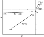
一方、図8は、本実施例で使用するブラック、シアンおよびグリーンのインクを記録媒体に記録した100%記録デューティの画像の反射光の色相を測定した結果を示す図である。反射光の測定は、市販の分光放射輝度計(CS−1000A:コニカミノルタ製)を用いて行い、その結果をa*b*平面上に示している。既に説明したように、ブロンズ現象は顔料本来の色の補色を示す傾向があるため、グリーンはヴァイオレットを、シアンはレッドを示している。また、ブラックインクの正反射光はイエローを示している。以下、ブロンズ現象によって白色光の正反射光が変色した場合の色味をブロンズ色と称する。 On the other hand, FIG. 8 is a diagram showing the result of measuring the hue of reflected light of an image with a 100% recording duty in which black, cyan, and green inks used in this embodiment are recorded on a recording medium. The reflected light is measured using a commercially available spectral radiance meter (CS-1000A: manufactured by Konica Minolta), and the result is shown on the a * b * plane. As already explained, since the bronze phenomenon tends to be complementary to the original color of the pigment, green indicates violet and cyan indicates red. Further, the regular reflected light of the black ink indicates yellow. Hereinafter, the tint when white light specularly reflected light changes due to the bronze phenomenon is referred to as a bronze color.
図8のような特徴を有するブラックインクを用いながら、モノクローム画像でブロンズ現象を抑えるためには、イエローのブロンズ色を抑えるブロンズ色を有する有彩色インクを記録することが望まれる。図8の例であれば、ブラックインクのブロンズ色を抑えるためには、シアンインクのブロンズ色(レッド)よりもグリーンインクのブロンズ色(ヴァイオレット)の方が、b*方向の成分を0に近づける効果が期待できる。 In order to suppress the bronze phenomenon in the monochrome image while using the black ink having the characteristics as shown in FIG. 8, it is desired to record chromatic ink having a bronze color that suppresses the bronze color of yellow. In the example of FIG. 8, in order to suppress the bronze color of the black ink, the bronze color of the green ink (violet) brings the component in the b * direction closer to 0 than the bronze color of the cyan ink (red). The effect can be expected.
この様に、顔料ブラックインクでは、色相ずれを補正するために好ましいインク色と、ブロンズ現象を補正するために好ましいインクとが、異なっていることが多い。 As described above, in the pigment black ink, the preferable ink color for correcting the hue shift and the preferable ink for correcting the bronze phenomenon are often different.
図6は、図5で示したブラックインクを用いてモノクローム画像を記録する際に、色相ずれを抑えることを目的とした色分解処理を行った場合の、信号値変換の様子を示した図である。図において、横軸は輝度濃度変換後の多値濃度データの濃度レベルに相当し、レベル数が大きいほど高濃度であることを意味する。一方、縦軸は各濃度レベルに対応して色分解処理から出力されるブラック、シアン、マゼンタの256値の多値データを示し、出力信号の大きさが記録媒体の単位領域に実際に記録されるドット数すなわち記録デューティに相応している。この色変換処理の例では、モノクローム画像の色相を補正するためにシアンとマゼンタのインクを使用する場合を示している。 FIG. 6 is a diagram showing a state of signal value conversion when color separation processing is performed for the purpose of suppressing hue deviation when recording a monochrome image using the black ink shown in FIG. is there. In the figure, the horizontal axis corresponds to the density level of the multi-value density data after luminance density conversion, and the higher the number of levels, the higher the density. On the other hand, the vertical axis indicates multi-value data of 256 values of black, cyan, and magenta output from the color separation process corresponding to each density level, and the magnitude of the output signal is actually recorded in the unit area of the recording medium. This corresponds to the number of dots to be recorded, that is, the recording duty. This example of color conversion processing shows a case where cyan and magenta inks are used to correct the hue of a monochrome image.
図によれば、粒状感の目立ち易い低濃度領域ではブラックインクを用いず、シアンとマゼンタでグレーを表現している。粒状感が目立ち難くなる程度の濃度レベルから、ブラックインクを記録するようにし、ブラックインクの色相がイエロー方向にずれる中濃度領域で、シアンとマゼンタの信号値は最大値となる。その後濃度レベルが上がるに連れ、ブラックの信号値が上昇しシアンおよびマゼンタの信号値は徐々に低下している。 According to the figure, in a low density region where the graininess is conspicuous, gray is expressed by cyan and magenta without using black ink. Black ink is recorded from a density level that makes the graininess inconspicuous, and the signal values of cyan and magenta are maximum values in a medium density region where the hue of the black ink shifts in the yellow direction. Thereafter, as the density level increases, the black signal value increases and the cyan and magenta signal values gradually decrease.
但し、シアンインクを多目に付与する図7の方法では、図8で示したようなブロンズ色の特徴を有するブラックインクを用いた場合、ブロンズ現象の軽減効果は期待できない。高濃度領域においては、ブラックインクのブロンズ色であるイエローとシアンインクのブロンズ色であるレッドとが加法混色し、赤茶色の強いブロンズ色が視認され、むしろ違和感を与えることが懸念される。すなわち、図6で示す色分解処理では、色相ずれを抑えることは出来ても、顔料インク特有のブロンズ現象を低減することは出来ない。 However, in the method of FIG. 7 in which cyan ink is applied to many, when the black ink having the bronze color characteristics as shown in FIG. 8 is used, the effect of reducing the bronze phenomenon cannot be expected. In the high density region, yellow, which is the bronze color of black ink, and red, which is the bronze color of cyan ink, are additively mixed, and a strong bronze color of reddish brown is visually recognized, which may cause a sense of incongruity. That is, in the color separation process shown in FIG. 6, even though the hue shift can be suppressed, the bronze phenomenon peculiar to the pigment ink cannot be reduced.
図8の場合には、ブロンズ現象を抑制するためには、シアンインクではなくグリーンインクを記録することが有効である。グリーンインクであれば、この補色であるヴァイオレットとイエローの加法混色によって、ブロンズ色の色相は白色(無彩色)に近づくので、ブロンズ現象が目立たなくなるからである。 In the case of FIG. 8, in order to suppress the bronze phenomenon, it is effective to record green ink instead of cyan ink. This is because, in the case of green ink, the bronze phenomenon becomes inconspicuous because the hue of the bronze color approaches white (achromatic color) due to the additive color mixture of violet and yellow, which are complementary colors.
但し、例えば図10に示すように、粒状感の目立ち易い低濃度領域や、色相ずれが目立ちやすい中濃度領域も含めた全濃度領域で、グリーンインクを積極的に使用してしまうと、シアンインクの場合よりも色転びが懸念されるようになる。何故なら、再度図5を参照するに、グリーンインクの色相の−b*方向の成分は、シアンインクよりも小さく、ブラックインクの色相ずれを抑えるには弱いので、シアンインクの場合よりも多くの量を記録しなければならないからである。 However, for example, as shown in FIG. 10, if green ink is actively used in all density areas including low density areas where graininess is noticeable and medium density areas where hue deviation is noticeable, cyan ink is used. There is more concern about color shift than in the case of. This is because, referring to FIG. 5 again, the component in the -b * direction of the hue of the green ink is smaller than that of the cyan ink, and is weak in suppressing the hue shift of the black ink. This is because the quantity must be recorded.
本発明者らは、鋭意検討の結果、上記色相ずれが問題になるのは主に低〜中濃度領域であり、ブロンズ現象が問題になるのは主に高濃度領域であることに着目した。そして、全階調領域で色相ずれもブロンズ現象も目立たない様にする為には、低〜中濃度領域では色相ずれの補正効果が高い有彩色インクを記録し、高濃度領域ではブロンズ現象の抑制効果が高い有彩色インクを記録することが、効果的であるという知見に至った。よって、本実施例では低〜中濃度領域では、色相ずれを補正するためにシアンインクを利用し、高濃度領域ではブロンズ現象を抑制するためにグリーンインクを使用する。 As a result of intensive studies, the present inventors have focused on the fact that the hue shift is a problem mainly in a low to medium density region, and the bronze phenomenon is a problem mainly in a high concentration region. In order to make the hue shift and bronze phenomenon inconspicuous in all gradation areas, record chromatic ink with a high hue shift correction effect in the low to medium density area, and suppress the bronze phenomenon in the high density area. The inventors have found that it is effective to record chromatic color ink having a high effect. Therefore, in this embodiment, cyan ink is used to correct hue deviation in the low to medium density region, and green ink is used to suppress the bronze phenomenon in the high density region.
図7は、色相のずれとブロンズ現象の両方を抑えるように作成した本実施例の色分解処理の信号値変換の様子を示す図である。本実施例の色変換処理では、色相ずれの方がブロンズ現象よりも目立ちやすい低濃度領域から中濃度領域では、モノクローム画像の色相を補正するためにシアンとマゼンタインクをグリーンインクよりも多く使用する。一方、色相ずれよりもブロンズ現象の方が目立ちやすい高濃度領域では、ブロンズ現象を抑制するためにグリーンインクをシアンやマゼンタインクよりも多く使用する。そして、いずれのインク色についても、濃度レベルの値に応じて出力信号値を連続的に且つ滑らかに変化させることによって、グリーンインクとシアン或いはマゼンタインクの出力信号値の大小関係が、濃度レベルに応じて自然な状態で逆転するようにしている。本実施例において、最高の濃度レベル255での、グリーンの出力信号値はその約15%である35程度になっている。
FIG. 7 is a diagram showing the state of signal value conversion in the color separation processing of the present embodiment created so as to suppress both hue shift and bronze phenomenon. In the color conversion processing of the present embodiment, cyan and magenta inks are used more than green ink to correct the hue of a monochrome image in a low density area to a medium density area where the hue shift is more conspicuous than the bronze phenomenon. . On the other hand, in a high density region where the bronze phenomenon is more conspicuous than the hue shift, more green ink is used than cyan or magenta ink in order to suppress the bronze phenomenon. For any ink color, by changing the output signal value continuously and smoothly according to the value of the density level, the magnitude relationship between the output signal values of the green ink and cyan or magenta ink is changed to the density level. In response, it reverses in a natural state. In this embodiment, the output signal value of green at the
なお、グリーンの出力信号値が大きいほどブロンズ現象の抑制効果は高いが、あまり大きすぎるとモノクローム画像の色相に影響が現れる。よって、濃度レベルの最高値におけるグリーンインク(有彩色インク)の出力信号値は、ブロンズ現象と色相ずれの両方が目立たない範囲に調整されることが好ましい。上記成分のインクを用いた場合には、グリーンインクの付与量がクブラックインク付与量の40%程度までに抑えることが望ましい。 Note that the greater the green output signal value, the higher the effect of suppressing the bronze phenomenon, but if it is too large, the hue of the monochrome image will be affected. Therefore, it is preferable that the output signal value of the green ink (chromatic ink) at the highest density level is adjusted in a range where both the bronze phenomenon and the hue shift are not noticeable. When ink of the above components is used, it is desirable that the amount of green ink applied is suppressed to about 40% of the amount of black ink applied.
このように、本実施例では、図7に示すような色分解処理を実行することによって、モノクローム画像における色相ずれとブロンズ現象の両方を好適に抑制することが可能となる。 Thus, in this embodiment, it is possible to suitably suppress both the hue shift and the bronzing phenomenon in the monochrome image by executing the color separation process as shown in FIG.
(評価)
以下、本実施例の検証のための実験およびその結果を説明する。
(Evaluation)
Hereinafter, an experiment for verifying the present embodiment and its result will be described.
本検証では、まず、図1〜図3に示すシリアル型のインクジェット記録装置を用い、1200dpiの解像度を有するブラックのパッチを、複数の濃度レベルに対応するように複数パッチ記録した。16パスの双方向マルチパス記録で記録した。インクの吐出量は4.5plであり、記録媒体はキヤノン製光沢紙(商品名「プレミアム光沢紙(厚口)」)を使用した。 In this verification, first, a plurality of black patches having a resolution of 1200 dpi were recorded so as to correspond to a plurality of density levels using the serial type ink jet recording apparatus shown in FIGS. Recording was performed by 16-pass bidirectional multi-pass recording. The ink ejection amount was 4.5 pl, and Canon glossy paper (trade name “Premium Glossy Paper (Thick))” was used as the recording medium.
ここでは、本実施例を従来の構成と比較するため、図6、図7および図10に示した色分解処理の夫々に基づいて、複数の濃度レベルに対応する複数のパッチを記録した。図6は、モノクローム画像の色相ずれを補正することを目的に、全階調領域でシアンとマゼンタのみを有彩色インクとして使用した場合の色分解処理を示し、これを使用した検討結果を比較例1と示す。図10は、モノクローム画像のブロンズ現象を低減することを目的に、全階調領域でグリーンインクのみを有彩色インクとして使用した場合の色分解処理を示し、これを使用した結果を比較例2と示す。図7は、モノクローム画像の色相ずれとブロンズ現象の両方を低減することを目的に、シアン、マゼンタおよびグリーンインクを有彩色インクとして使用した場合の色分解処理を示し、これを使用した結果を実施例と示す。 Here, in order to compare this example with the conventional configuration, a plurality of patches corresponding to a plurality of density levels were recorded based on each of the color separation processes shown in FIG. 6, FIG. 7, and FIG. FIG. 6 shows a color separation process when only cyan and magenta are used as chromatic inks in all gradation regions for the purpose of correcting a hue shift of a monochrome image. 1 is shown. FIG. 10 shows a color separation process when only the green ink is used as the chromatic color ink in all gradation regions for the purpose of reducing the bronze phenomenon of the monochrome image. Show. FIG. 7 shows the color separation process when cyan, magenta and green inks are used as chromatic inks for the purpose of reducing both the hue shift and bronzing phenomenon of monochrome images, and the results of using these are shown. An example is shown.
そして、上記3例の夫々について、濃度レベルが255に相当するパッチのブロンズ色を、分光放射輝度計(CS−1000A:コニカミノルタ製)を用いての測定し、黒色としての見栄えを目視で判断した。また、複数の階調のパッチの色相を比較することにより、色転び(色相ずれ)の状態も評価した。 Then, for each of the above three examples, the bronze color of the patch corresponding to a density level of 255 is measured using a spectral radiance meter (CS-1000A: manufactured by Konica Minolta), and the appearance as black is visually determined. did. Moreover, the state of color transition (hue shift) was also evaluated by comparing the hues of a plurality of gradation patches.
図9は、上記測定のおよび目視判断の結果を示す図である。 FIG. 9 is a diagram showing the results of the above measurement and visual judgment.
ブロンズ色の測定結果において、グリーンインクを使用している本実施例と比較例2では、シアンインクを使用している比較例1に比べて特にb*成分が小さくなり、ブロンズ色の彩度が抑えられていることがわかる。 In the measurement result of the bronze color, the b * component is particularly small in the present example using the green ink and the comparative example 2 compared to the comparative example 1 using the cyan ink, and the bronze color saturation is high. You can see that it is suppressed.
黒の見栄えについては、シアンの付加によって赤茶色のブロンズ色が視認される比較例1に比べ、本実施例と比較例2のパッチは好適な黒色が得られていることが判る。 With regard to the appearance of black, it can be seen that the patch of this example and Comparative Example 2 has a favorable black color compared to Comparative Example 1 in which a reddish-brown bronze color is visually recognized by the addition of cyan.
色転びの状態については、ブラックインクの記録量に対し有彩色の付与量の割合が大きい比較例2において、色転びの懸念(程度)が強いことがわかる。 Regarding the state of color shift, it can be seen that there is a strong concern (degree) of color shift in Comparative Example 2 in which the ratio of the amount of chromatic color applied to the black ink recording amount is large.
以上の結果より、図7で示した色分解処理を採用した本実施例の方法が、ブロンズ現象、黒色の見栄え、色転び現象の全てにおいて良好であることが検証された。 From the above results, it was verified that the method of this example employing the color separation processing shown in FIG. 7 is good in all of the bronze phenomenon, the black appearance, and the color shift phenomenon.
以上説明した様に本実施例では、モノクローム画像を記録する際に、低〜中濃度領域ではシアンインクをグリーンインクよりも多く付与することによって色相ずれを抑制する。また、高濃度領域ではグリーンインクをシアンインクよりも多く付与することによってブロンズ現象を抑制する。これにより、全ての濃度領域において色相ずれもブロンズ現象も目立たない高品位なモノクローム画像を出力することが可能となる。 As described above, in this embodiment, when a monochrome image is recorded, hue deviation is suppressed by applying more cyan ink than green ink in a low to medium density region. In the high density region, the bronzing phenomenon is suppressed by applying more green ink than cyan ink. As a result, it is possible to output a high-quality monochrome image in which neither hue shift nor bronze phenomenon is noticeable in all density regions.
(その他の実施形態)
本発明で適用可能なインクは、上記実施例に示した組成に限定されるものではなく、特に一般的なブラックインクと複数のカラーインクの組み合わせであればよい。上記実施例では、含有する色材を顔料として説明してきたが、染料インクであってもブロンズ現象が目立つ場合には、本発明は有効に機能する。
(Other embodiments)
The ink applicable in the present invention is not limited to the composition shown in the above embodiment, and may be a combination of a general black ink and a plurality of color inks. In the above embodiment, the color material contained has been described as a pigment, but the present invention functions effectively when the bronze phenomenon is noticeable even with dye ink.
以上では、モノクローム画像の色相の補正を行うために、シアンインクとマゼンタインクを使用し、ブロンズ現象を補正するためにグリーンインクを使用する例で説明したが、本発明はこれに限定されるものではない。記録媒体の種類やインクの成分等によっては、ブラックインクの色相が図5とは異なる方向に位置する場合もあり、ブラックインクのブロンズ色が図8とは異なる方向を持つ場合もある。このような場合には、色相ずれやブロンズ色のそれぞれの色相成分に基づいて、これらを補正する方向の成分を有するインクを1以上選択し、これらインクを適切な割合で使用すればよい。 In the above description, the cyan ink and magenta ink are used to correct the hue of the monochrome image, and the green ink is used to correct the bronze phenomenon. However, the present invention is not limited to this. is not. Depending on the type of recording medium, ink components, etc., the hue of the black ink may be located in a different direction from that in FIG. 5, and the bronze color of the black ink may have a different direction from that in FIG. In such a case, it is only necessary to select one or more inks having a component in a direction for correcting them based on the hue components of hue shift and bronze color, and use these inks at an appropriate ratio.
例えば、ブラックインクのブロンズ色が−b*方向に彩度をもつ場合には、高濃度領域ではグリーンインクではなくレッドインクを記録する方が、ブロンズ現象を抑制するのに効果的である。また、ブラックインクの色相が、低〜中濃度領域の中でも濃度レベルに応じて変動するような場合には、色相ずれを補正するための有彩色インクを濃度レベルに応じて切り替えていくようにしてもよい。いずれにしても、濃度レベルが相対的に低い低〜中濃度領域ではブラックインクの色相とは反対成分を有する1以上の有彩色インク(第1のインク)を用いればよい。そして同時に、濃度レベルが相対的に高い高濃度領域ではブラックインクのブロンズ色とは反対成分のブロンズ色を有する1以上の有彩色インク(第2の有彩色インク)を用いて記録すればよい。このような第1の有彩色インクと第2の有彩色インクを濃度レベルに応じて調整しながら記録することにより、本発明の効果を得ることが出来る。 For example, when the bronze color of black ink has a saturation in the −b * direction, recording red ink instead of green ink in the high density region is more effective in suppressing the bronzing phenomenon. In addition, when the hue of the black ink fluctuates depending on the density level in the low to medium density region, the chromatic ink for correcting the hue shift is switched according to the density level. Also good. In any case, one or more chromatic inks (first inks) having a component opposite to the hue of the black ink may be used in the low to medium density region where the density level is relatively low. At the same time, in a high density region where the density level is relatively high, recording may be performed using one or more chromatic color inks (second chromatic color inks) having a bronze color component opposite to the bronze color of the black ink. By recording while adjusting the first chromatic color ink and the second chromatic color ink according to the density level, the effect of the present invention can be obtained.
また、以上ではモノクローム画像を記録するために、主として1種類のブラックインクを用いる場合について説明したが、例えばグレーインクやライトグレーインクのように異なる濃度の無彩色インクを複数用意し、夫々に対して色相ずれを補正することも出来る。この様な構成を採用すると、グレーインクのドットはブラックインクよりも目立ちにくいため、低〜中濃度領域での有彩色インクの記録を抑え、色転びを軽減することが可能となる。 In the above description, a case where one type of black ink is mainly used to record a monochrome image has been described. However, for example, a plurality of achromatic inks having different densities such as gray ink and light gray ink are prepared. It is also possible to correct the hue shift. When such a configuration is adopted, since the gray ink dots are less noticeable than the black ink, it is possible to suppress the recording of the chromatic color ink in the low to medium density region and reduce the color shift.
また、上記実施例では、個々のノズルの内部に電気熱変換体を備えた例で説明したが、本発明はこの様なインクジェット記録ヘッドに限定されるものではない。インクを吐出させるためのエネルギ発生手段としては、個々のノズルの内部に圧電素子を配備する形態であってもよい。 In the above-described embodiment, an example in which an electrothermal transducer is provided inside each nozzle has been described. However, the present invention is not limited to such an ink jet recording head. As an energy generation means for discharging ink, a form in which a piezoelectric element is provided inside each nozzle may be employed.
更に、以上の実施例では、ブラックインクが有する色相の彩度を0に近づけ、なるべく無彩色のモノクローム画像を記録する場合について説明してきたが、本発明はこの様な形態に限定されるものではない。近年では、同じモノクローム画像であっても、全体的にやや青み帯びた冷黒調のモノクローム画像や、赤みを帯びた温黒調のモノクローム画像を、ユーザの好みに応じて選択的に出力できる記録装置も提供されている。この様な場合であっても、低〜中濃度領域において、目的の色相に合わせるようにブラックインク以外の1以上の有彩色インクが適量に記録されれば、本発明の効果を得ることは出来る。 Furthermore, in the above embodiment, the case where the saturation of the hue of the black ink is brought close to 0 and a monochrome image having an achromatic color is recorded as much as possible has been described. However, the present invention is not limited to such a form. Absent. In recent years, even the same monochrome image can be selectively output according to the user's preference, as a whole, a slightly bluish cold black-and-white monochrome image or a reddish warm-black monochrome image An apparatus is also provided. Even in such a case, the effect of the present invention can be obtained if at least one chromatic color ink other than the black ink is recorded in an appropriate amount so as to match the target hue in the low to medium density region. .
更に、以上の実施例では、予め用意したLUTを用いて、輝度濃度変換処理と色分解処理とを一括して行う構成の色変換処理で説明したが、本発明はこのような構成に限定されるものではない。図7に示す意味合いの変換処理(すなわち、低〜中濃度領域で色相を補正するための有彩色インクが記録され、高濃度領域でブロンズ現象を低減するための有彩色インクが記録されるような処理)が行われていれば、本発明の効果は得られ、その範疇に含まれる。例えば、そのような意味合いがパラメータとして定められた変換式を用いて、ブラックの濃度データを算出変換する形態とすることも出来る。 Furthermore, in the above embodiment, the description has been given of the color conversion process in which the luminance density conversion process and the color separation process are collectively performed using the LUT prepared in advance. However, the present invention is limited to such a structure. It is not something. The meaning conversion process shown in FIG. 7 (that is, chromatic ink for correcting the hue in the low to medium density region is recorded and chromatic ink for reducing the bronze phenomenon is recorded in the high density region. If processing is performed, the effect of the present invention can be obtained and included in the category. For example, black density data may be calculated and converted using a conversion formula in which such meaning is defined as a parameter.
更に、上記実施例では、本発明の特徴的な処理を行う記録制御部305がインクジェット記録装置内部に備えられている形態の画像処理装置について説明したが、記録制御部305はインクジェット記録装置内部に備えられている必要はない。例えば、インクジェット記録装置と接続されるホスト装置302のプリンタドライバに上記記録制御部305の機能を持たせるようにしてもよい。この場合、プリンタドライバが、多値の輝度データに基づいて図4に示した一連の処理を実行し、生成した2値データを記録装置に供給する形態になる。このように、ホスト装置とインクジェット記録装置を含んで構成されるインクジェット記録システムも本発明の範疇である。この場合、ホスト装置は、インクジェット記録装置供給するデータを生成するための画像処理装置として機能する。
Furthermore, in the above-described embodiment, the image processing apparatus in which the
つまり、本発明の特徴は、記録制御部305にて実行されるデータ処理にある。従って、本発明の特徴的なデータ処理を行う記録制御部305を備えた画像処理装置が本発明の範疇である。記録制御部305がインクジェット記録装置に備えられている場合、このインクジェット記録装置が本発明の画像処理装置として機能し、記録制御部305がホスト装置に備えられている場合、このホスト装置が本発明の画像処理装置として機能する。
That is, a feature of the present invention is data processing executed by the
更に、上述した特徴的なデータ処理をコンピュータに実行させるコンピュータ可読プログラムや、そのプログラムをコンピュータにより読み出し可能に格納した記憶媒体も本発明の範疇である。 Furthermore, a computer-readable program that causes a computer to execute the characteristic data processing described above and a storage medium that stores the program so as to be readable by the computer are also within the scope of the present invention.
54 記録ヘッド
102 顔料インクノズル列
103 クリアインクノズル列
104 不吐出領域
54 Recording head 102 Pigment ink nozzle row 103 Clear ink nozzle row 104 Non-ejection area
Claims (17)
前記記録媒体上に前記第1の有彩色インクのみが付与された画像の正反射光の測定結果が示す色相は、前記記録媒体上に前記第2の有彩色インクのみが付与された画像の正反射光の測定結果が示す色相よりも、前記記録媒体上に前記無彩色インクのみが付与された画像の正反射光の測定結果が示す色相に近く、
前記モノクローム画像の濃度レベルが第1の濃度レベルを示す場合には、前記第2の有彩色インクを付与せずに前記無彩色インクおよび前記第1の有彩色インクを付与するための濃度データを生成し、前記モノクローム画像の濃度レベルが前記第1の濃度レベルよりも高い濃度を示す第2の濃度レベル以上のレベルを示す場合には、前記レベルが高くなるに従って前記第2の有彩色インクの付与量が増加するように、前記無彩色インクおよび前記第2の有彩色インクを付与するための濃度データを生成することを特徴とする画像処理方法。 An image processing method for recording a monochrome image on a recording medium by applying an achromatic color ink, a first chromatic color ink, and a second chromatic color ink different from the first chromatic color ink. There,
The hue indicated by the measurement result of the specular reflection light of the image on which only the first chromatic color ink is applied on the recording medium is the hue of the image on which only the second chromatic color ink is applied on the recording medium. Closer to the hue indicated by the measurement result of specular reflection light of the image in which only the achromatic ink is applied on the recording medium than the hue indicated by the measurement result of reflected light,
When the density level of the monochrome image indicates the first density level, density data for applying the achromatic color ink and the first chromatic color ink without applying the second chromatic color ink is provided. When the density level of the monochrome image generated is higher than the second density level, which is higher than the first density level, the second chromatic ink of the second chromatic ink increases as the level increases. An image processing method comprising: generating density data for applying the achromatic color ink and the second chromatic color ink so that the applied amount increases.
前記記録媒体上に前記第1の有彩色インクのみが付与された画像の正反射光の測定結果が示す色相は、前記記録媒体上に前記第2の有彩色インクのみが付与された画像の正反射光の測定結果が示す色相よりも、前記記録媒体上に前記無彩色インクのみが付与された画像の正反射光の測定結果が示す色相に近く、
前記モノクローム画像の濃度レベルが第1の濃度レベルを示す場合には、前記第2の有彩色インクを付与せずに前記無彩色インクおよび前記第1の有彩色インクを付与するための濃度データを生成し、前記モノクローム画像の濃度レベルが前記第1の濃度レベルよりも高い濃度を示す第2の濃度レベル以上のレベルを示す場合には、前記レベルが高くなるに従って前記第2の有彩色インクの付与量が増加するように、前記無彩色インクおよび前記第2の有彩色インクを付与するための濃度データを生成することを特徴とする画像処理装置。 An image processing apparatus for recording a monochrome image on a recording medium by applying an achromatic color ink, a first chromatic color ink, and a second chromatic color ink different from the first chromatic color ink. There,
The hue indicated by the measurement result of the specular reflection light of the image on which only the first chromatic color ink is applied on the recording medium is the hue of the image on which only the second chromatic color ink is applied on the recording medium. Closer to the hue indicated by the measurement result of specular reflection light of the image in which only the achromatic ink is applied on the recording medium than the hue indicated by the measurement result of reflected light,
When the density level of the monochrome image indicates the first density level, density data for applying the achromatic color ink and the first chromatic color ink without applying the second chromatic color ink is provided. When the density level of the monochrome image generated is higher than the second density level, which is higher than the first density level, the second chromatic ink of the second chromatic ink increases as the level increases. An image processing apparatus that generates density data for applying the achromatic color ink and the second chromatic color ink so that the applied amount increases.
モノクローム画像が示す濃度レベルを取得する取得工程と、
前記取得工程において取得した前記濃度レベルに基づいて、無彩色インクの付与量およびグリーンインクの付与量を決定する決定工程と、
を備え、
a * b * 平面上において、所定のデューティで前記無彩色インクのみが付与された画像の正反射光を測定した第1測定結果のb * 成分の正負を示す符号は、前記所定のデューティで前記グリーンインクのみが付与された画像の正反射光を測定した第2測定結果のb * 成分の正負を示す符号とは逆であることを特徴とする画像処理方法。 An image processing method for recording a monochrome image on a recording medium,
An acquisition step of acquiring a density level indicated by the monochrome image;
A determination step of determining an achromatic ink application amount and a green ink application amount based on the density level acquired in the acquisition step;
Equipped with a,
On the a * b * plane, the sign indicating the positive / negative of the b * component of the first measurement result obtained by measuring the specularly reflected light of the image to which only the achromatic color ink is applied at a predetermined duty is the predetermined duty. An image processing method characterized in that the sign is opposite to a sign indicating the sign of the b * component of the second measurement result obtained by measuring specular reflection light of an image to which only green ink is applied.
前記a*b*平面上において、前記第2測定結果のb*成分の絶対値は、前記所定のデューティで前記有彩色インクのみが付与された画像の正反射光を測定した第3測定結果のb*成分の絶対値よりも小さいことを特徴とする請求項11に記載の画像処理方法。 When the density level acquired in the acquisition step is a predetermined value, in the determination step, the application amount of the chromatic color ink having a hue different from the hue of the green ink is determined to be greater than 0,
On the a * b * plane, the absolute value of the b * component of the second measurement result is the value of the third measurement result obtained by measuring the specularly reflected light of the image to which only the chromatic ink is applied at the predetermined duty. The image processing method according to claim 11 , wherein the image processing method is smaller than an absolute value of the b * component.
モノクローム画像が示す濃度レベルを取得する取得手段と、
前記取得工程において取得した前記濃度レベルに基づいて、無彩色インクの付与量およびグリーンインクの付与量を決定する決定手段と、
を備え、
a * b * 平面上において、所定のデューティで前記無彩色インクのみが付与された画像の正反射光を測定した第1測定結果のb * 成分の正負を示す符号は、前記所定のデューティで前記グリーンインクのみが付与された画像の正反射光を測定した第2測定結果のb * 成分の正負を示す符号とは逆であることを特徴とする画像処理装置。 An image processing apparatus for recording a monochrome image on a recording medium,
Acquisition means for acquiring a density level indicated by the monochrome image;
Determining means for determining the amount of achromatic ink applied and the amount of green ink applied based on the density level acquired in the acquiring step;
With
On the a * b * plane, the sign indicating the positive / negative of the b * component of the first measurement result obtained by measuring the specularly reflected light of the image to which only the achromatic color ink is applied at a predetermined duty is the predetermined duty. An image processing apparatus characterized in that the sign is opposite to a sign indicating the sign of the b * component of the second measurement result obtained by measuring specular reflection light of an image to which only green ink is applied.
Priority Applications (2)
| Application Number | Priority Date | Filing Date | Title |
|---|---|---|---|
| JP2009284027A JP5538858B2 (en) | 2009-12-15 | 2009-12-15 | Image processing apparatus and image processing method |
| US12/962,455 US8654393B2 (en) | 2009-12-15 | 2010-12-07 | Image processor and image processing method |
Applications Claiming Priority (1)
| Application Number | Priority Date | Filing Date | Title |
|---|---|---|---|
| JP2009284027A JP5538858B2 (en) | 2009-12-15 | 2009-12-15 | Image processing apparatus and image processing method |
Publications (3)
| Publication Number | Publication Date |
|---|---|
| JP2011126023A JP2011126023A (en) | 2011-06-30 |
| JP2011126023A5 JP2011126023A5 (en) | 2013-02-07 |
| JP5538858B2 true JP5538858B2 (en) | 2014-07-02 |
Family
ID=44142567
Family Applications (1)
| Application Number | Title | Priority Date | Filing Date |
|---|---|---|---|
| JP2009284027A Active JP5538858B2 (en) | 2009-12-15 | 2009-12-15 | Image processing apparatus and image processing method |
Country Status (2)
| Country | Link |
|---|---|
| US (1) | US8654393B2 (en) |
| JP (1) | JP5538858B2 (en) |
Families Citing this family (7)
| Publication number | Priority date | Publication date | Assignee | Title |
|---|---|---|---|---|
| US5715832A (en) | 1995-02-28 | 1998-02-10 | Boston Scientific Corporation | Deflectable biopsy catheter |
| JP5539119B2 (en) * | 2010-08-31 | 2014-07-02 | キヤノン株式会社 | Image processing method, image processing apparatus, and ink jet recording method |
| JP6144975B2 (en) * | 2013-06-26 | 2017-06-07 | 理想科学工業株式会社 | Inkjet printing device |
| JP2016066830A (en) * | 2014-09-22 | 2016-04-28 | キヤノン株式会社 | Image processing apparatus, image processing method and program |
| JP6848288B2 (en) * | 2016-09-16 | 2021-03-24 | セイコーエプソン株式会社 | Printing equipment, printing methods, and computer programs |
| JP6848287B2 (en) * | 2016-09-16 | 2021-03-24 | セイコーエプソン株式会社 | Printing equipment, printing methods, and computer programs |
| JP7131019B2 (en) * | 2018-03-28 | 2022-09-06 | セイコーエプソン株式会社 | Recording device and recording method |
Family Cites Families (17)
| Publication number | Priority date | Publication date | Assignee | Title |
|---|---|---|---|---|
| US7253922B2 (en) | 2001-03-07 | 2007-08-07 | Seiko Epson Corporation | Monochromatic printer and image processing apparatus |
| JP3922052B2 (en) * | 2001-03-07 | 2007-05-30 | セイコーエプソン株式会社 | Monochromatic printer and image processing apparatus |
| JP4003046B2 (en) * | 2002-02-21 | 2007-11-07 | セイコーエプソン株式会社 | PRINT CONTROL DEVICE, PRINT CONTROL METHOD, PRINT SYSTEM, PRINT CONTROL PROGRAM, AND MEDIUM CONTAINING PRINT CONTROL PROGRAM |
| JP4066338B2 (en) | 2002-11-29 | 2008-03-26 | セイコーエプソン株式会社 | Inkjet recording method, recording system, and recorded matter |
| US20040209017A1 (en) * | 2003-04-15 | 2004-10-21 | Zahrobsky Peter C. | Weak base modification of porous ink-jet media coating for enhanced image quality |
| US7775618B2 (en) | 2003-11-13 | 2010-08-17 | Canon Kabushiki Kaisha | Recording apparatus and data processing method |
| JP2005238835A (en) | 2004-01-30 | 2005-09-08 | Canon Inc | Image forming method, program, and image forming system |
| JP2005212360A (en) * | 2004-01-30 | 2005-08-11 | Canon Inc | Image forming method, image processing method and ink jet recorder |
| US7936481B2 (en) | 2004-01-30 | 2011-05-03 | Canon Kabushiki Kaisha | Method, system and program for forming an image |
| WO2006001540A1 (en) * | 2004-06-28 | 2006-01-05 | Canon Kabushiki Kaisha | Cyan ink, ink set, set of ink and reactive liquid, and image forming method |
| US7384461B2 (en) * | 2004-12-21 | 2008-06-10 | Brother Kogyo Kabushiki Kaisha | Water-based ink set for ink-jet recording and ink-jet recording method |
| JP2006299127A (en) * | 2005-04-21 | 2006-11-02 | Brother Ind Ltd | Water-based ink set for ink jet recording and method for ink jet recording |
| JP4875396B2 (en) * | 2006-04-12 | 2012-02-15 | キヤノン株式会社 | Color processing apparatus and method |
| JP2007318671A (en) * | 2006-05-29 | 2007-12-06 | Canon Inc | Image processing apparatus, recording apparatus, and image processing method |
| JP4958483B2 (en) * | 2006-06-19 | 2012-06-20 | キヤノン株式会社 | Recording device |
| JP4935204B2 (en) * | 2006-06-26 | 2012-05-23 | セイコーエプソン株式会社 | Image creating apparatus, image creating method, and image creating program |
| JP4675296B2 (en) * | 2006-07-24 | 2011-04-20 | セイコーエプソン株式会社 | Printing apparatus and printing method |
-
2009
- 2009-12-15 JP JP2009284027A patent/JP5538858B2/en active Active
-
2010
- 2010-12-07 US US12/962,455 patent/US8654393B2/en active Active
Also Published As
| Publication number | Publication date |
|---|---|
| US20110141502A1 (en) | 2011-06-16 |
| US8654393B2 (en) | 2014-02-18 |
| JP2011126023A (en) | 2011-06-30 |
Similar Documents
| Publication | Publication Date | Title |
|---|---|---|
| JP5538858B2 (en) | Image processing apparatus and image processing method | |
| JP5539120B2 (en) | Inkjet recording apparatus and inkjet recording method | |
| US8485629B2 (en) | Printing apparatus, printing method, and data generating apparatus | |
| JP5539122B2 (en) | Image processing method and image processing apparatus | |
| US8882228B2 (en) | Image processing apparatus, inkjet printing apparatus and image processing method | |
| JP5539119B2 (en) | Image processing method, image processing apparatus, and ink jet recording method | |
| JP5618496B2 (en) | Inkjet recording apparatus and inkjet recording method | |
| US8733894B2 (en) | Recording apparatus and color sample table | |
| JP2012011727A (en) | Inkjet recording apparatus | |
| JP5988909B2 (en) | Image processing apparatus and image processing method | |
| JP2012051199A (en) | Inkjet recorder | |
| JP5473257B2 (en) | Inkjet recording apparatus and inkjet recording method | |
| US9007653B2 (en) | Image processing apparatus and image processing method for printing an image using colored ink and clear liquid | |
| US9227423B2 (en) | Image processing apparatus, inkjet printing apparatus, and inkjet printing method | |
| JP2011178108A (en) | Data generating device, inkjet recording device, and data generating method | |
| JP6141030B2 (en) | Image processing apparatus and image processing method | |
| JP2011110755A (en) | Device and method for inkjet recording | |
| JP6141124B2 (en) | Inkjet recording method and inkjet recording system | |
| JP6821469B2 (en) | Recording device and recording method | |
| JP5859059B2 (en) | Inkjet recording apparatus and inkjet recording method | |
| JP2013237197A (en) | Inkjet recording apparatus and inkjet recording method | |
| JP2011121209A (en) | Recording apparatus, and recording method |
Legal Events
| Date | Code | Title | Description |
|---|---|---|---|
| A521 | Request for written amendment filed |
Free format text: JAPANESE INTERMEDIATE CODE: A523 Effective date: 20121217 |
|
| A621 | Written request for application examination |
Free format text: JAPANESE INTERMEDIATE CODE: A621 Effective date: 20121217 |
|
| A977 | Report on retrieval |
Free format text: JAPANESE INTERMEDIATE CODE: A971007 Effective date: 20130830 |
|
| A131 | Notification of reasons for refusal |
Free format text: JAPANESE INTERMEDIATE CODE: A131 Effective date: 20130910 |
|
| A521 | Request for written amendment filed |
Free format text: JAPANESE INTERMEDIATE CODE: A523 Effective date: 20131111 |
|
| A131 | Notification of reasons for refusal |
Free format text: JAPANESE INTERMEDIATE CODE: A131 Effective date: 20131217 |
|
| A521 | Request for written amendment filed |
Free format text: JAPANESE INTERMEDIATE CODE: A523 Effective date: 20140214 |
|
| TRDD | Decision of grant or rejection written | ||
| A01 | Written decision to grant a patent or to grant a registration (utility model) |
Free format text: JAPANESE INTERMEDIATE CODE: A01 Effective date: 20140401 |
|
| R151 | Written notification of patent or utility model registration |
Ref document number: 5538858 Country of ref document: JP Free format text: JAPANESE INTERMEDIATE CODE: R151 |
|
| A61 | First payment of annual fees (during grant procedure) |
Free format text: JAPANESE INTERMEDIATE CODE: A61 Effective date: 20140430 |