JP5536282B2 - Fuel injection valve - Google Patents
Fuel injection valve Download PDFInfo
- Publication number
- JP5536282B2 JP5536282B2 JP2013516496A JP2013516496A JP5536282B2 JP 5536282 B2 JP5536282 B2 JP 5536282B2 JP 2013516496 A JP2013516496 A JP 2013516496A JP 2013516496 A JP2013516496 A JP 2013516496A JP 5536282 B2 JP5536282 B2 JP 5536282B2
- Authority
- JP
- Japan
- Prior art keywords
- fuel
- tube
- injection valve
- valve
- close contact
- Prior art date
- Legal status (The legal status is an assumption and is not a legal conclusion. Google has not performed a legal analysis and makes no representation as to the accuracy of the status listed.)
- Active
Links
Images

Classifications
-
- F—MECHANICAL ENGINEERING; LIGHTING; HEATING; WEAPONS; BLASTING
- F02—COMBUSTION ENGINES; HOT-GAS OR COMBUSTION-PRODUCT ENGINE PLANTS
- F02M—SUPPLYING COMBUSTION ENGINES IN GENERAL WITH COMBUSTIBLE MIXTURES OR CONSTITUENTS THEREOF
- F02M61/00—Fuel-injectors not provided for in groups F02M39/00 - F02M57/00 or F02M67/00
- F02M61/16—Details not provided for in, or of interest apart from, the apparatus of groups F02M61/02 - F02M61/14
- F02M61/18—Injection nozzles, e.g. having valve seats; Details of valve member seated ends, not otherwise provided for
- F02M61/1853—Orifice plates
-
- F—MECHANICAL ENGINEERING; LIGHTING; HEATING; WEAPONS; BLASTING
- F02—COMBUSTION ENGINES; HOT-GAS OR COMBUSTION-PRODUCT ENGINE PLANTS
- F02M—SUPPLYING COMBUSTION ENGINES IN GENERAL WITH COMBUSTIBLE MIXTURES OR CONSTITUENTS THEREOF
- F02M61/00—Fuel-injectors not provided for in groups F02M39/00 - F02M57/00 or F02M67/00
- F02M61/16—Details not provided for in, or of interest apart from, the apparatus of groups F02M61/02 - F02M61/14
- F02M61/18—Injection nozzles, e.g. having valve seats; Details of valve member seated ends, not otherwise provided for
-
- F—MECHANICAL ENGINEERING; LIGHTING; HEATING; WEAPONS; BLASTING
- F02—COMBUSTION ENGINES; HOT-GAS OR COMBUSTION-PRODUCT ENGINE PLANTS
- F02M—SUPPLYING COMBUSTION ENGINES IN GENERAL WITH COMBUSTIBLE MIXTURES OR CONSTITUENTS THEREOF
- F02M2200/00—Details of fuel-injection apparatus, not otherwise provided for
- F02M2200/16—Sealing of fuel injection apparatus not otherwise provided for
Landscapes
- Engineering & Computer Science (AREA)
- Chemical & Material Sciences (AREA)
- Combustion & Propulsion (AREA)
- Mechanical Engineering (AREA)
- General Engineering & Computer Science (AREA)
- Fuel-Injection Apparatus (AREA)
Description
本発明は、燃料噴射弁に係り、さらに詳細には、局所部位に燃料を集中噴射するように備えられた内燃機関の燃料噴射弁に関する。 The present invention relates to a fuel injection valve, and more particularly, to a fuel injection valve for an internal combustion engine that is provided so that fuel is concentratedly injected at a local site.
一般的に、インジェクターと呼ばれる燃料噴射弁は、圧力を持つ液体をノズルから噴射させる装置である。普通ディーゼルエンジンでは、ニードル弁によって燃料の圧力が設定された値に到逹すれば燃料を噴射し、ガソリンエンジンでは、コンピュータから送って来る噴射信号によって燃料を噴射するように、ソレノイドが内蔵されている噴射ノズルである。ニードル弁は、プランジャーと一体になっており、燃料噴射弁に噴射信号が伝達されれば、噴射信号によって磁化されたプランジャーと一体化しているボール弁及び弁シャフトが引き寄せられて噴孔が開かれ、それと同時に燃料が噴射される。燃料の噴射量は、ニードル弁の開放時間、すなわち、ソレノイドコイルの通電時間によって定められる。 Generally, a fuel injection valve called an injector is a device that injects a liquid having pressure from a nozzle. In a normal diesel engine, a fuel is injected when the fuel pressure reaches a value set by a needle valve. In a gasoline engine, a solenoid is built in so that fuel is injected by an injection signal sent from a computer. It is a spray nozzle. The needle valve is integrated with the plunger, and when the injection signal is transmitted to the fuel injection valve, the ball valve and valve shaft integrated with the plunger magnetized by the injection signal are attracted and the injection hole is formed. At the same time, fuel is injected. The fuel injection amount is determined by the opening time of the needle valve, that is, the energization time of the solenoid coil.
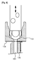
かかる既存の燃料噴射弁は、燃料噴射弁の先端と燃料チューブとの流路が当接形態に組み合わせられていて、組み合わせられた部品の結合公差が形成され、これらの結合公差によって、燃料噴射弁の先端と燃料チューブとの間に隙間ができて燃料が外部に流出される場合がある。すなわち、図8に示したように、燃料噴射弁の下端に位置する弁シート103の底面と燃料チューブ106の上端面との間に介在されるオリフィス板104と燃料チューブ106との間に結合公差が生ずる場合、燃料通路106の流路161から噴射される燃料が、図8に矢印で示されたように燃料通路106の外に流出される。
In such an existing fuel injection valve, the flow path between the tip of the fuel injection valve and the fuel tube is combined in a contact form, and a combined tolerance of the combined parts is formed, and the fuel injection valve is formed by these combined tolerances. There may be a gap between the tip of the fuel and the fuel tube, and the fuel may flow out to the outside. That is, as shown in FIG. 8, the coupling tolerance between the
このように外部に流出された燃料は、気化しつつ燃料噴射弁の燃料噴射弁表面に残留物質を残す。このように燃料噴射弁の表面に堆積されている残留物質は、燃料噴射弁の噴射口の面積を縮めることで燃料噴射弁の性能を劣化させ、流出された燃料の一部は、車の外部まで放出されて大気汚染を引き起こす。 Thus, the fuel that has flowed to the outside leaves a residual substance on the surface of the fuel injection valve while being vaporized. The residual material deposited on the surface of the fuel injection valve in this way deteriorates the performance of the fuel injection valve by reducing the area of the injection port of the fuel injection valve, and a part of the fuel that has flowed out is outside the vehicle. Will be released to cause air pollution.
また、燃料噴射弁の噴射口周辺に堆積物を固着させ、車整備時に堆積物除去のための洗浄コストをさらに発生させる。 In addition, deposits are fixed around the injection port of the fuel injection valve, and a cleaning cost for removing deposits is further generated during vehicle maintenance.
また、テフロン(登録商標)などの相対的に柔らかい素材を使う燃料チューブは、燃料噴射弁と誤整列された状態に組み合わせられやすいので、組み立てはもとより燃料流出をさらに劣化させる。 In addition, since a fuel tube using a relatively soft material such as Teflon (registered trademark) is easily combined with a fuel injection valve in a misaligned state, fuel outflow is further deteriorated as well as assembly.
また、燃料噴射弁から噴射された燃料が流路を離脱して外部に流出されれば、車の出力及び燃費などの性能も悪くなるという問題点があった。 Further, if the fuel injected from the fuel injection valve leaves the flow path and flows out to the outside, there is a problem that the performance such as the output of the vehicle and the fuel efficiency deteriorates.
本発明は、前記従来の問題点を解決するためになされたものであり、その目的は、燃料噴射弁の先端に、燃料噴射弁のオリフィス板と燃料チューブとの間に隙間ができることを防止するためのチューブアダプタを取り付けることで、オリフィス板と燃料チューブとの隙間を通って流出された燃料が気化しつつ燃料噴射弁のノズル表面に残留物質を堆積させる現象を防止するので、残留物質によるノズルの噴射口面積の縮小及び燃料噴射弁の性能劣化を防止し、燃料流出による燃料噴射弁の寿命短縮を抑制し、燃料の流出を防止するための追加装置の除去が可能であり、車の性能改善及び大気汚染予防の可能な燃料噴射弁を提供するところにある。 The present invention has been made to solve the above-described conventional problems, and an object thereof is to prevent a gap from being formed between the orifice plate of the fuel injection valve and the fuel tube at the tip of the fuel injection valve. By attaching a tube adapter for this purpose, the fuel that has flowed out through the gap between the orifice plate and the fuel tube is prevented from vaporizing while the residual material is deposited on the nozzle surface of the fuel injection valve. It is possible to reduce the fuel injection valve area and prevent the fuel injection valve performance from deteriorating, suppress the shortening of the fuel injection valve life due to the fuel outflow, and remove additional devices to prevent the fuel outflow. A fuel injection valve capable of improving and preventing air pollution is provided.
また、本発明の他の目的は、燃料噴射弁の内部に燃料チューブの一部分を組み合わせて燃料噴射弁と燃料チューブとの隙間が発生せず、燃料チューブと弁ハウジングとの接触面に気密維持部材を割り込んで燃料流出を二重に防止した燃料噴射弁を提供するところにある。 Another object of the present invention is to combine a part of the fuel tube inside the fuel injection valve so that a gap between the fuel injection valve and the fuel tube does not occur, and an airtight maintaining member is formed on the contact surface between the fuel tube and the valve housing. Therefore, a fuel injection valve that doubles the fuel outflow and prevents the fuel from flowing out is provided.
また、本発明の他の目的は、前記のように燃料流出を二重に防止することにおいて、燃料流出の防止に使われる部品をコンパクト化することで燃料密封性能や噴射性能を害せず、かえって向上させつつ燃料流出の防止のための部品の製造工程やコストを低減させる燃料噴射弁を提供するところある。 In addition, another object of the present invention is to prevent fuel spillage double as described above, and to make the parts used for preventing fuel spilling compact so as not to impair fuel sealing performance and injection performance. On the other hand, there is a need to provide a fuel injection valve that improves the manufacturing process and cost of parts for preventing fuel outflow while improving.
前述の課題を解決するために本発明は、内燃機関用燃料噴射弁において、弁ハウジングの内部で移動するニードルと、前記ニードルの開閉する開閉孔が内部に形成される弁シートと、前記弁シートの下部に密着し、噴射ホールを通じて燃料が噴射されるオリフィス板と、前記オリフィス板から噴射される燃料が内燃機関に供給される通路である燃料チューブと、前記オリフィス板から前記燃料チューブに供給される燃料の流出を防止するために、前記オリフィス板と前記燃料チューブとの間に設けられるチューブアダプタと、を備えることを特徴とする。 In order to solve the aforementioned problems, the present invention provides a fuel injection valve for an internal combustion engine, a needle that moves inside a valve housing, a valve seat in which an opening and closing hole for opening and closing the needle is formed, and the valve seat An orifice plate that is in close contact with the lower portion of the nozzle, and fuel is injected through an injection hole; a fuel tube that is a passage through which fuel injected from the orifice plate is supplied to the internal combustion engine; and a fuel tube that is supplied from the orifice plate to the fuel tube. In order to prevent the fuel from flowing out, a tube adapter provided between the orifice plate and the fuel tube is provided.
また、本発明の前記チューブアダプタは、前記オリフィス板の底面に密着する密着部と、前記密着部の外側が下方に折り曲げられる外側折り曲げ部と、を備えることを特徴とする。 In addition, the tube adapter according to the present invention is provided with a close contact portion that is in close contact with the bottom surface of the orifice plate, and an outer bent portion in which an outer side of the close contact portion is bent downward.
また、本発明の前記チューブアダプタは、前記密着部の内側が下方に折り曲げられる内側折り曲げ部をさらに備えることを特徴とする。 In addition, the tube adapter of the present invention further includes an inner bent portion in which an inner side of the close contact portion is bent downward.
また、本発明の前記内側折り曲げ部は、外周面が、前記燃料チューブの上面中心部で前記燃料チューブ流路と連結されるように形成された円形溝の内周面に挿入固定されるか、または内周面が前記燃料チューブの上面外周面に形成された段差に圧入固定されることを特徴とする。 Further, the inner bent portion of the present invention is inserted and fixed to the inner peripheral surface of a circular groove formed so that the outer peripheral surface is connected to the fuel tube flow path at the center of the upper surface of the fuel tube, Alternatively, the inner peripheral surface is press-fitted and fixed to a step formed on the outer peripheral surface of the upper surface of the fuel tube.
また、本発明の前記燃料チューブは、前記オリフィス板の底面に密着するようにその上端にフランジ部が突設されたことを特徴とする。 Further, the fuel tube of the present invention is characterized in that a flange portion projects from the upper end of the fuel tube so as to be in close contact with the bottom surface of the orifice plate.
また、本発明では、前記フランジ部の外周面が弁ハウジングの内周面と密着または離隔することを特徴とする。 Moreover, in this invention, the outer peripheral surface of the said flange part is closely_contact | adhered or spaced apart from the inner peripheral surface of a valve housing, It is characterized by the above-mentioned.
また、本発明では、前記フランジ部の外周面と前記弁ハウジングの内周面とが密着した時、密着面に密封部材が割り込むことを特徴とする。 In the present invention, when the outer peripheral surface of the flange portion and the inner peripheral surface of the valve housing are in close contact with each other, a sealing member is inserted into the close contact surface.
また、本発明では、前記フランジ部の外周面と前記弁ハウジングの内周面とが離隔すれば、前記オリフィス板の表面が前記弁シートの底面と隣接する前記弁ハウジングの内壁に密着することを特徴とする。 In the present invention, if the outer peripheral surface of the flange portion and the inner peripheral surface of the valve housing are separated, the surface of the orifice plate is in close contact with the inner wall of the valve housing adjacent to the bottom surface of the valve seat. Features.
また、本発明では、前記チューブアダプタの外側折り曲げ部は、前記弁ハウジングの内壁に溶接結合されることを特徴とする。 In the present invention, the outer bent portion of the tube adapter is welded to the inner wall of the valve housing.
本発明はまた、内燃機関用燃料噴射弁において、弁ハウジングの内部で移動するニードルと、前記ニードルの開閉する開閉孔が内部に形成される弁シートと、前記弁ハウジングから噴射される燃料が内燃機関に供給される通路である燃料チューブと、前記弁シートと前記燃料チューブとの間に介在されて噴射ホールを通って燃料を噴射し、前記噴射ホールから噴射された燃料が前記燃料チューブとの間に流出されることを防止するチューブアダプタと、を備えることを特徴とする。 The present invention also provides a fuel injection valve for an internal combustion engine, wherein a needle that moves inside the valve housing, a valve seat in which an opening and closing hole for opening and closing the needle is formed, and fuel injected from the valve housing is internal combustion A fuel tube, which is a passage supplied to the engine, is interposed between the valve seat and the fuel tube and injects fuel through an injection hole, and the fuel injected from the injection hole is in contact with the fuel tube. And a tube adapter that prevents it from flowing out between them.
また、本発明では、前記チューブアダプタは、前記弁シートの底面に密着する密着部と、前記密着部の外側で下方に折り曲げられる外側折り曲げ部と、前記燃料チューブの流路に挿入されて前記流路面に密着するように、前記密着部の内側で下方に突出する内側折り曲げ部と、を備えることを特徴とする。 Also, in the present invention, the tube adapter is inserted into the flow path of the fuel tube by being inserted into a close contact portion that is in close contact with the bottom surface of the valve seat, an outer bent portion that is bent downward outside the close contact portion, and the flow path of the fuel tube. And an inner bent portion that protrudes downward inside the contact portion so as to be in close contact with a road surface.
また、本発明では、前記内側折り曲げ部は、前記噴射ホールに向かって内径が段々縮まるように円錐状傾斜部を形成していることを特徴とする。 In the present invention, the inner bent portion is characterized in that a conical inclined portion is formed so that the inner diameter gradually decreases toward the injection hole.
また、本発明では、前記内側折り曲げ部は、前記流路の傾斜面下端まで前記傾斜面に沿って延びる傾斜部分と、前記傾斜部分の下端で前記流路の軸線と直交するように延びる平坦部分と、で形成される円錐台状になっていることを特徴とする。 In the present invention, the inner bent portion includes an inclined portion extending along the inclined surface to the lower end of the inclined surface of the flow path, and a flat portion extending at right angles to the axis of the flow path at the lower end of the inclined portion. And a truncated cone shape formed by:
以下、本発明の燃料噴射弁を、添付図面を参照して実施例を説明すれば、次の通りである。 Hereinafter, embodiments of the fuel injection valve of the present invention will be described with reference to the accompanying drawings.
<第1実施例>
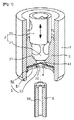
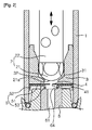
本実施例による燃料噴射弁は、図1及び図2に示したように、弁ハウジング1、ニードル2、弁シート3、オリフィス板4、チューブアダプタ5及び燃料チューブ6を備える。
<First embodiment>
As shown in FIGS. 1 and 2, the fuel injection valve according to this embodiment includes a
前記弁ハウジング1は、ソレノイドコイルの通電時に磁気通路を構成するように縦方向のホール内部にニードル2が設けられる。
The
前記ニードル2は、前記弁ハウジング1の内部に備えられて、電源印加時に電磁気回路によって長手方向に移動し、ボール弁21及び弁シャフト22で構成される。
The
前記ボール弁21は、その底面に閉鎖面21aが形成され、前記弁シャフト22は、ボール弁21の上端に溶接などで相互結合されて弁ハウジング1の長手方向に沿って移動する。
The
前記弁シート3は、前記弁ハウジング1の内部に備えられて内部下端にボール弁21の閉鎖面21aが密着または分離される接触面31が形成され、前記接触面31から底面まで連結される開閉孔32が形成される。
The
この時、前記ボール弁21の閉鎖面21aが開閉孔32と連結される接触面31に完全接触すれば燃料供給が中止され、ボール弁21の閉鎖面21aが接触面31から離隔すれば燃料供給が行われるが、離隔程度によって燃料供給量が調節される。
At this time, the fuel supply is stopped if the
前記オリフィス板4は、前記弁シート3の下端に密着して設けられる円板状であり、燃料の通過時に流量測定及び流量調節などを行うための噴射ホール41が中心部に形成される。
The
ここで、前記噴射ホール41は、前記オリフィス板4の中心に1つが形成されると例示したが、1つでありつつスリット状に形成されてもよく、ホールまたはスリット状の複数が円周方向に沿って等間隔で配されるように形成される。
Here, the
このように、前記噴射ホール41が円周方向に沿って複数形成される場合、チューブアダプタ5の内側折り曲げ部53の内側に位置させることが望ましく、燃料粒子の微粒化をさらに促進させるようにオリフィス板4の厚さを低減させることで噴射ホール41の直径をさらに縮める。
As described above, when a plurality of the injection holes 41 are formed along the circumferential direction, the injection holes 41 are preferably positioned inside the inner
前記チューブアダプタ5は、オリフィス板4と燃料チューブ6との間に割り込んで前記オリフィス板4の噴射ホール41と前記燃料チューブ6の流路61とを隙間なく密着させ、燃料が流路61外部への流出を防止する。
The
この時、前記チューブアダプタ5は、円板状である密着部51と、前記密着部51の外側端が下方に折り曲げ形成される外側折り曲げ部52と、前記密着部51の中心部にホールが形成されると同時に前記ホールの内側端が下方に折り曲げられる内側折り曲げ部53と、を備える。
At this time, the
すなわち、前記チューブアダプタ5の結合構造は、弁ハウジング1の内部に挿入されて噴射ホール41を干渉せずにオリフィス板4の底面に重ねて当てられた密着部51と、密着部51の外側エッジから下方に折り曲げ形成される外側折り曲げ部52と、密着部51の中心部底面に燃料チューブ6と結合されるように下方に折り曲げられ、外周面が燃料チューブ6の流路61の内周面に挿入固定される内側折り曲げ部53と、で構成される。
That is, the coupling structure of the
特に、チューブアダプタ5の内側折り曲げ部53が下方に折り曲げられるので、前記内側折り曲げ部53の形状と対応するように、燃料チューブ6の上面中心部に流路61と連結される円形溝64が形成される。このように、前記チューブアダプタ5の内側折り曲げ部53の外周面が、燃料チューブ6の上面中心部に形成された円形溝の内周面に挿入固定されるので、挿入方式による結合が容易であるという利点がある。
In particular, since the inner
さらに、前記チューブアダプタ5は、外側折り曲げ部52の外周面が、弁ハウジング1の外部から加える熱によって前記弁ハウジング1の内周面に溶接結合される。
Further, the
前記燃料チューブ6は、オリフィス板4の噴射ホール41から噴射される燃料が内燃機関(図示せず)に供給される通路であり、上端は、チューブアダプタ5によってオリフィス板4の底面に密着し、下端は内燃機関に連結される。
The
結局、前記実施例は、燃料チューブ6によって、燃料噴射弁と燃料チューブ6との間に隙間がなくてもメンテナンスのための分離が容易である。
After all, in the embodiment, the
<第2実施例>
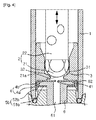
本実施例による燃料噴射弁は、図3に示したように、弁ハウジング1、ニードル2、弁シート3、オリフィス板4、チューブアダプタ5a及び燃料チューブ6を備え、弁ハウジング1、ニードル2、弁シート3及びオリフィス板4は、第1実施例のそれと同じ構造及び機能を持っているので、詳細な説明は略する。
<Second embodiment>
As shown in FIG. 3, the fuel injection valve according to the present embodiment includes a
前記チューブアダプタ5aは、オリフィス板4と燃料チューブ6との間に割り込んで前記オリフィス板4の噴射ホール41と前記燃料チューブ6の流路61とを隙間なく密着させて、燃料の流路外部への流出を防止する。
The tube adapter 5a is inserted between the
この時、前記チューブアダプタ5aは、円板状の密着部51aと、前記密着部51aのエッジから下方に折り曲げ形成される外側折り曲げ部52aと、前記密着部51aの中心部にホールが形成されると同時に前記ホールの内側端が下方に折り曲げられる内側折り曲げ部53aと、を備える。
At this time, the tube adapter 5a has a disc-shaped
特に、前記内側折り曲げ部53aは、第1実施例とは異なって内周面が燃料チューブ6の外周面に圧入固定されるので、燃料チューブ6との結合力を向上させる。
In particular, unlike the first embodiment, the inner
そして、前記チューブアダプタ5aの内側折り曲げ部53aが下方に折り曲げられるので、前記内側折り曲げ部53aの内径形状に対応するように燃料チューブ6の上面外周面に段差65が形成される。
And since the inner
また、前記チューブアダプタ5aも、外側折り曲げ部52aの外周面が、弁ハウジング1の外部から加える熱によって前記弁ハウジング1の内周面に溶接結合される。
The tube adapter 5a is also welded to the inner peripheral surface of the
結局、前記実施例は、燃料チューブ6の上端が燃料噴射弁内に圧入されるので、燃料噴射弁と燃料チューブ6との間に間隔がなくてもメンテナンスのための分離が容易であり、相互結合力が向上する。
After all, in the above embodiment, since the upper end of the
<第3実施例>
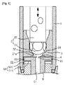
本実施例による燃料噴射弁は、図4に示したように、弁ハウジング1、ニードル2、弁シート3、オリフィス板4、チューブアダプタ5b及び燃料チューブ6を備え、弁ハウジング1、ニードル2及び弁シート3は、第1及び第2実施例のそれと同じ構造及び機能を持っているので、詳細な説明は略する。
<Third embodiment>
As shown in FIG. 4, the fuel injection valve according to the present embodiment includes a
前記オリフィス板4は、その中心部に燃料の通過時に流量測定及び流量調節などを行うための噴射ホール41が形成され、弁シート3の下端に接触する弁シート密着面4aと、弁シート密着面4aのエッジから下方に折り曲げ形成されて、前記弁シート3の下端と隣接する弁ハウジング1の内周面に密着して設けられる弁ハウジング接触折り曲げ部4bと、で構成される。
The
前記チューブアダプタ5bは、燃料チューブ6の上端に形成されたフランジ部62の底面と弁ハウジング1の内周面とに密着するように備えられ、燃料チューブ6のフランジ部62をオリフィス板4側に密着させて、燃料の流路外部への流出を防止する。
The
さらに、前記チューブアダプタ5bは、弁シート3の底面に密着する密着部51bの中心部を貫通した燃料チューブ6のフランジ部62の底面にチューブアダプタ5bの上面が接するように、貫通ホールが形成される。
Further, the
前記燃料チューブ6は、前記のようにオリフィス板4のエッジにハウジング接触折り曲げ部4bが備えられるので、フランジ部62が弁ハウジング1の内周面と離隔した状態に備えられる。
Since the
結局、前記実施例は、燃料チューブ6の上端に形成されたフランジ部62が燃料噴射弁内に組み合わせられるので、燃料噴射弁と燃料チューブ6との間に隙間が発生しないという利点がある。
After all, the embodiment has an advantage that no gap is generated between the fuel injection valve and the
したがって、前記実施例は、1次的に、燃料チューブ6の上端に形成されたフランジ部62が前記チューブアダプタ5bによって前記オリフィス板4側に密着するので、燃料の流路外部への流出が防止され、2次的に、前記チューブアダプタ5bの外側折り曲げ部52bが弁ハウジング1の内周面に溶接結合されるので、燃料の流路外部への流出が防止される。
Therefore, in the first embodiment, the
<第4実施例>
本発明のさらに他の実施例による燃料噴射弁は、図5に示したように、弁ハウジング1、ニードル2、弁シート3、オリフィス板4、チューブアダプタ5c及び燃料チューブ6を備え、弁ハウジング1、ニードル2、弁シート3及びオリフィス板4は、前記の第1及び第2実施例のそれと同じ構造及び機能を持っているので、詳細な説明は略する。
<Fourth embodiment>
As shown in FIG. 5, the fuel injection valve according to still another embodiment of the present invention includes a
前記チューブアダプタ5cは、その上面が燃料チューブ6のフランジ部62の底面に隣接するように位置され、前記フランジ部62の外周面と弁ハウジング1の内周面との間に、オーリング(O−ring)などの密封部材63を割り込めて燃料の漏れを防止する。
The tube adapter 5 c is positioned such that the upper surface thereof is adjacent to the bottom surface of the
この時、前記チューブアダプタ5cは、円板状の密着部51cと、前記密着部51cのエッジから下方に折り曲げ形成される外側折り曲げ部52cと、で構成され、前記密着部51cの中心部には、燃料チューブ6が貫通してフランジ部62の底面にチューブアダプタ5cの上面が接するように、貫通ホールが形成される。
At this time, the tube adapter 5c is composed of a disc-shaped
前記燃料チューブ6は、フランジ部62の外周面が弁ハウジング1の内周面に密着した状態に備えられ、前記弁ハウジング1の内周面との間にオーリングなどの密封部材63がさらに備えられる。
The
結局、前記実施例は、1次的に、燃料チューブ6の上端に形成されたフランジ部62が前記チューブアダプタ5bによって前記オリフィス板4側に密着するので、燃料の流路外部への流出が防止され、2次的に、前記チューブアダプタ5bの外側折り曲げ部52cが弁ハウジング1の内周面に溶接結合されるので、燃料の流路外部への流出が防止されるだけでなく、3次的に、燃料チューブ6のフランジ部62の外周面に備えられた密封部材63によって、燃料の流路外部への流出が防止される。
After all, in the embodiment, the
<第5実施例>
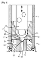
本発明のさらに他の実施例による燃料噴射弁は、図6に示したように、ニードル2、弁シート3、燃料チューブ6、及びチューブアダプタ5を備えて構成されるところ、特に、ニードル2と弁シート3、そして燃料チューブ6の一部を除外すれば、前記の第1ないし第4実施例とほぼ同じところ、これらに関する詳細な説明は本実施例では略する。特に、本実施例による燃料噴射弁は、図6から分かるように、他の実施例のオリフィス板とチューブアダプタとの機能が、1つのチューブアダプタ5に統合されている。
<Fifth embodiment>
As shown in FIG. 6, the fuel injection valve according to still another embodiment of the present invention includes a
前記チューブアダプタ5は、弁シート3と燃料チューブ6との間に割り込んで噴射ホール41を通じて燃料を噴射するようになっているところ、噴射ホール41から噴射された燃料が燃料チューブ6との間から流出されることを防止する。このために、チューブアダプタ5は、図6に示したように、薄板を折り曲げたワッシャー状に製造され、密着部51、外側折り曲げ部52、及び内側折り曲げ部53で形成される。
The
ここで、先ず、前記密着部51は、前記他の実施例のオリフィス板と同様に弁シート3の底面に密着する部分であり、内側折り曲げ部53によって中心部分が円形に凹んでいるディスク形態になっている。また、前記外側折り曲げ部52は、前記の他の実施例のチューブアダプタの外側折り曲げ部と同様に、密着部51外側の外側端部分を下方に折り曲げて形成するところ、その外周面が、弁ハウジング1の外部から加える熱によって弁ハウジング1の内周面に溶接結合される。最後に、前記内側折り曲げ部53は、密着部51の中心部分に形成された円形部分の内側エッジを下方に折り曲げて凹状に形成するところ、図6に示したように、燃料チューブ6の流路61に挿入されて流路61の流路面に密着する。ここで、内側折り曲げ部53は多様な形態に形成できるところ、図6に示したように、チューブ6側に突出したノズル状に形成できるが、この場合には、下端の噴射ホール41に向かって内径が段々縮まるテーパード円錐状傾斜部に形成される。
First, the
したがって、前記実施例によれば、チューブアダプタとオリフィス板とが1つに統合されるので、全体工数が短縮され、したがって、コストダウンを図ることができる。それだけでなく、流路61内に挿入されるチューブアダプタ6の深さが深くなり、中央に集まる円錐状の特性上自動で中心が整列されるので、燃料噴射弁と燃料チューブ6との結合力が高くなり、チューブアダプタ6と燃料チューブ6との密封性能が向上する。
Therefore, according to the said Example, since a tube adapter and an orifice board are integrated into one, the whole man-hour is shortened, Therefore Cost reduction can be aimed at. In addition, the depth of the
<第6実施例>
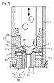
一方、本発明のさらに他の実施例による燃料噴射弁が図7に図示されるが、この実施例による燃料噴射弁は、第5実施例と同じく、オリフィス板とチューブアダプタとの機能が一つのチューブアダプタ5に統合されるところ、密着部51、外側折り曲げ部52、及び内側折り曲げ部53で形成される。
<Sixth embodiment>
On the other hand, a fuel injection valve according to still another embodiment of the present invention is shown in FIG. 7, but the fuel injection valve according to this embodiment has the functions of the orifice plate and the tube adapter as in the fifth embodiment. When integrated with the
ここで、本実施例で適用されるチューブアダプタ5は、図7に示したように、内側折り曲げ部53が傾斜部分53−1と平坦部分53−2との2部分で形成されるところ、傾斜部分53−1は、流路61上端の傾斜面の上端角から傾斜面が終わる下端角まで前記傾斜面に沿って載置されるように円錐台状になっており、平坦部分53−2は、傾斜部分53−1の下端で折り曲げられて流路61の軸線と直交するように平坦に延設される。
Here, as shown in FIG. 7, the
結果的に、前記実施例によれば、前記の第5実施例のように、チューブアダプタとオリフィス板との統合で全体工数の低減及びコストダウンを図ることができ、円錐状の傾斜部分の特性上、燃料噴射弁と燃料チューブ6との結合力を高め、チューブアダプタ6と燃料チューブ6との密封性能を向上させる。また、噴射ホール41が平坦部分53−2に貫通されているので、量産時に噴射ホール41の加工性能を向上させるだけでなく、噴射ホール41を通って流路61に噴射される燃料の噴射安定性を向上させる。
As a result, according to the embodiment, as in the fifth embodiment, the integration of the tube adapter and the orifice plate can reduce the total man-hours and reduce the cost, and the characteristics of the conical inclined portion. In addition, the coupling force between the fuel injection valve and the
以上で説明した本発明の詳細な説明では、本発明の望ましい実施例を参照までに説明したが、本発明の保護範囲は前記実施例に限定されるものではなく、当業者ならば、本発明の思想及び技術領域から逸脱しない範囲内で本発明を多様に修正及び変更できるということを理解できるであろう。 In the detailed description of the present invention described above, the preferred embodiments of the present invention have been described above. However, the protection scope of the present invention is not limited to the above-described embodiments, and those skilled in the art will recognize the present invention. It will be understood that the present invention can be variously modified and changed without departing from the spirit and technical scope of the present invention.
<産業上の利用可能性>
本発明の燃料噴射弁は、燃料噴射弁の先端に、燃料噴射弁のオリフィス板と燃料チューブとの間に隙間ができることを防止するためのチューブアダプタを取り付けることで、オリフィス板と燃料チューブとの隙間を通って流出された燃料が気化しつつ燃料噴射弁のノズル表面に残留物質を堆積させる現象を防止するので、残留物質によるノズルの噴射口面積の縮小及び燃料噴射弁の性能劣化を防止し、燃料流出による燃料噴射弁の寿命短縮を抑制し、燃料の流出を防止するための追加装置の除去が可能であり、車の性能改善及び大気汚染予防の効果がある。
<Industrial applicability>
In the fuel injection valve of the present invention, a tube adapter for preventing a gap from being formed between the orifice plate of the fuel injection valve and the fuel tube is attached to the tip of the fuel injection valve. Prevents the phenomenon that fuel flowing out through the gap evaporates and deposits residual material on the nozzle surface of the fuel injection valve, preventing the reduction of nozzle injection nozzle area and fuel injection valve performance degradation due to residual material. Further, it is possible to suppress the shortening of the life of the fuel injection valve due to the fuel spill, and to remove an additional device for preventing the fuel spill, thereby improving the performance of the vehicle and preventing air pollution.
また、燃料噴射弁の内部に燃料チューブの一部分を組み合わせて燃料噴射弁と燃料チューブとの隙間が発生せず、燃料チューブと弁ハウジングとの接触面に気密維持部材を割り込んで燃料流出を二重に防止する効果がある。 In addition, by combining a part of the fuel tube inside the fuel injection valve, there is no gap between the fuel injection valve and the fuel tube, and an airtightness maintaining member is inserted into the contact surface between the fuel tube and the valve housing to double the fuel outflow. Has the effect of preventing.
さらに、チューブアダプタとオリフィス板とを1つのチューブアダプタに統合して製造工程を低減し、それによってコストダウンでき、燃料噴射弁と燃料チューブとの結合力及び密封性能を向上させると共に、燃料チューブに噴射される燃料の噴射性能の向上も図ることができる。 Furthermore, the tube adapter and the orifice plate are integrated into one tube adapter to reduce the manufacturing process, thereby reducing the cost, improving the coupling force between the fuel injection valve and the fuel tube and the sealing performance, The injection performance of the injected fuel can also be improved.
Claims (9)
弁ハウジングの内部で移動するニードルと、
前記ニードルの開閉する開閉孔が内部に形成される弁シートと、
前記弁シートの下部に密着し、噴射ホールを通じて燃料が噴射されるオリフィス板と、
前記オリフィス板から噴射される燃料が内燃機関に供給される通路である燃料チューブと、
前記オリフィス板から前記燃料チューブに供給される燃料の流出を防止するために、前記オリフィス板と前記燃料チューブとの間に設けられるチューブアダプタと、を備え、
前記チューブアダプタは、
前記オリフィス板の底面に密着する密着部と、
前記密着部の外側が下方に折り曲げられる外側折り曲げ部と、
前記密着部の内側が下方に折り曲げられる内側折り曲げ部と、を備えることを特徴とする燃料噴射弁。 In a fuel injection valve for an internal combustion engine,
A needle moving inside the valve housing;
A valve seat in which an opening and closing hole for opening and closing the needle is formed;
An orifice plate that is in close contact with the lower part of the valve seat and injects fuel through an injection hole;
A fuel tube which is a passage through which fuel injected from the orifice plate is supplied to the internal combustion engine;
A tube adapter provided between the orifice plate and the fuel tube in order to prevent outflow of fuel supplied from the orifice plate to the fuel tube ;
The tube adapter is
A close contact portion in close contact with the bottom surface of the orifice plate;
An outer bent portion where the outer side of the contact portion is bent downward;
A fuel injection valve, characterized in Rukoto provided with an inner bent portion which inwardly bent below the contact portion.
弁ハウジングの内部で移動するニードルと、
前記ニードルの開閉する開閉孔が内部に形成される弁シートと、
前記弁シートの下部に密着し、噴射ホールを通じて燃料が噴射されるオリフィス板と、
前記オリフィス板から噴射される燃料が内燃機関に供給される通路である燃料チューブと、
前記オリフィス板から前記燃料チューブに供給される燃料の流出を防止するために、前記オリフィス板の下方に設けられるチューブアダプタと、を備え、
前記燃料チューブは、前記オリフィス板の底面及び前記チューブアダプタの上面に密着するようにその上端にフランジ部が突設されたことを特徴とする燃料噴射弁。 In a fuel injection valve for an internal combustion engine,
A needle moving inside the valve housing;
A valve seat in which an opening and closing hole for opening and closing the needle is formed;
An orifice plate that is in close contact with the lower part of the valve seat and injects fuel through an injection hole;
A fuel tube which is a passage through which fuel injected from the orifice plate is supplied to the internal combustion engine;
In order to prevent the fuel supplied from the orifice plate to the fuel tube from flowing out, a tube adapter provided below the orifice plate, and
It said fuel tube, fuel injection valve you characterized in that the flange portion is projected at its upper end so as to be in close contact with the bottom surface and an upper surface of the tube adapter of the orifice plate.
弁ハウジングの内部で移動するニードルと、
前記ニードルの開閉する開閉孔が内部に形成される弁シートと、
前記弁ハウジングから噴射される燃料が内燃機関に供給される通路である燃料チューブと、
前記弁シートと前記燃料チューブとの間に介在されて噴射ホールを通って燃料を噴射し、前記噴射ホールから噴射された燃料が前記燃料チューブとの間に流出されることを防止するチューブアダプタと、を備え、
前記チューブアダプタは、
前記弁シートの底面に密着する密着部と、
前記密着部の外側で下方に折り曲げられる外側折り曲げ部と、
前記燃料チューブの流路に挿入されて前記流路面に密着するように、前記密着部の内側で下方に突出する内側折り曲げ部と、を備えることを特徴とする燃料噴射弁。 In a fuel injection valve for an internal combustion engine,
A needle moving inside the valve housing;
A valve seat in which an opening and closing hole for opening and closing the needle is formed;
A fuel tube which is a passage through which fuel injected from the valve housing is supplied to the internal combustion engine;
A tube adapter that is interposed between the valve seat and the fuel tube and injects fuel through an injection hole and prevents the fuel injected from the injection hole from flowing out between the fuel tube; , equipped with a,
The tube adapter is
A close contact portion that is in close contact with the bottom surface of the valve seat;
An outer bent portion that is bent downward on the outer side of the contact portion;
Wherein As is inserted into the flow path of the fuel tube in close contact with the flow path surface, a fuel injection valve, characterized in Rukoto provided with an inner bent portion projecting downward inside said contact portion.
前記流路の傾斜面下端まで前記傾斜面に沿って延びる傾斜部分と、
前記傾斜部分の下端で前記流路の軸線と直交するように延びる平坦部分と、で形成される円錐台状になっていることを特徴とする請求項8に記載の燃料噴射弁。 The inner bent portion is
An inclined portion extending along the inclined surface to the lower end of the inclined surface of the flow path;
9. The fuel injection valve according to claim 8 , wherein the fuel injection valve has a truncated cone shape formed by a lower end of the inclined portion and a flat portion extending perpendicular to the axis of the flow path.
Applications Claiming Priority (3)
| Application Number | Priority Date | Filing Date | Title |
|---|---|---|---|
| KR10-2010-0059417 | 2010-06-23 | ||
| KR1020100059417A KR101160043B1 (en) | 2010-06-23 | 2010-06-23 | Fuel injection valve |
| PCT/KR2011/003734 WO2011162484A2 (en) | 2010-06-23 | 2011-05-20 | Fuel injection valve |
Publications (2)
| Publication Number | Publication Date |
|---|---|
| JP2013530344A JP2013530344A (en) | 2013-07-25 |
| JP5536282B2 true JP5536282B2 (en) | 2014-07-02 |
Family
ID=45371903
Family Applications (1)
| Application Number | Title | Priority Date | Filing Date |
|---|---|---|---|
| JP2013516496A Active JP5536282B2 (en) | 2010-06-23 | 2011-05-20 | Fuel injection valve |
Country Status (5)
| Country | Link |
|---|---|
| EP (1) | EP2587046B1 (en) |
| JP (1) | JP5536282B2 (en) |
| KR (1) | KR101160043B1 (en) |
| CN (1) | CN102985679B (en) |
| WO (1) | WO2011162484A2 (en) |
Families Citing this family (2)
| Publication number | Priority date | Publication date | Assignee | Title |
|---|---|---|---|---|
| DE102016206996B3 (en) * | 2016-04-25 | 2017-08-31 | Continental Automotive Gmbh | Switching valve for a fuel injection system and high-pressure fuel pump |
| DE102017223866A1 (en) * | 2017-12-29 | 2019-07-04 | Robert Bosch Gmbh | Valve for metering a fluid, in particular fuel injection valve |
Family Cites Families (11)
| Publication number | Priority date | Publication date | Assignee | Title |
|---|---|---|---|---|
| DE19736548A1 (en) * | 1997-08-22 | 1999-02-25 | Bosch Gmbh Robert | Fuel injector for internal combustion engine |
| JPH11210603A (en) * | 1998-01-29 | 1999-08-03 | Aisan Ind Co Ltd | Fuel injection device |
| JP2000145590A (en) * | 1998-11-10 | 2000-05-26 | Aisan Ind Co Ltd | Fuel injection valve |
| JP2000314360A (en) * | 1999-04-30 | 2000-11-14 | Aisan Ind Co Ltd | Fuel injection valve |
| JP2002174160A (en) * | 2000-12-05 | 2002-06-21 | Toyota Motor Corp | Injector |
| US6783087B2 (en) * | 2001-04-09 | 2004-08-31 | Nippon Soken, Inc. | Fuel injector |
| JP2003003932A (en) * | 2001-06-19 | 2003-01-08 | Hitachi Unisia Automotive Ltd | Fuel injection valve |
| JP4289291B2 (en) * | 2004-12-16 | 2009-07-01 | 株式会社デンソー | Fuel injection valve |
| KR20060091776A (en) * | 2005-02-15 | 2006-08-22 | 현대자동차주식회사 | Injector |
| KR100719463B1 (en) * | 2006-06-16 | 2007-05-18 | 주식회사 케피코 | Fuel injection valve |
| KR100719462B1 (en) * | 2006-06-16 | 2007-05-18 | 주식회사 케피코 | Car injectors |
-
2010
- 2010-06-23 KR KR1020100059417A patent/KR101160043B1/en active Active
-
2011
- 2011-05-20 CN CN201180031271.8A patent/CN102985679B/en active Active
- 2011-05-20 EP EP11798319.7A patent/EP2587046B1/en active Active
- 2011-05-20 WO PCT/KR2011/003734 patent/WO2011162484A2/en not_active Ceased
- 2011-05-20 JP JP2013516496A patent/JP5536282B2/en active Active
Also Published As
| Publication number | Publication date |
|---|---|
| KR20110139374A (en) | 2011-12-29 |
| EP2587046A2 (en) | 2013-05-01 |
| JP2013530344A (en) | 2013-07-25 |
| WO2011162484A3 (en) | 2012-02-16 |
| EP2587046B1 (en) | 2019-07-03 |
| EP2587046A4 (en) | 2017-10-11 |
| CN102985679A (en) | 2013-03-20 |
| CN102985679B (en) | 2015-09-16 |
| KR101160043B1 (en) | 2012-06-25 |
| WO2011162484A2 (en) | 2011-12-29 |
Similar Documents
| Publication | Publication Date | Title |
|---|---|---|
| US9528480B2 (en) | Valve assembly for an injection valve and injection valve | |
| US8430343B2 (en) | Fuel injection valve | |
| US9599083B2 (en) | Fuel injection valve | |
| US6814312B2 (en) | Fuel injection valve | |
| KR20010102344A (en) | Fuel injector with turbulence generator for fuel orifice | |
| JPH0942114A (en) | Fuel injection valve | |
| KR100420748B1 (en) | Fuel injection valve | |
| US20030155440A1 (en) | Fuel injection valve | |
| CN102828873A (en) | Valve assembly for injection valve and injection valve | |
| JP5536282B2 (en) | Fuel injection valve | |
| CN105378264B (en) | Fuel injection valves for combustion engines | |
| WO2017126259A1 (en) | Fuel injection valve | |
| JP2004512458A (en) | Fuel injection valve | |
| JP2005517122A (en) | Fuel injection valve | |
| JP2006258035A (en) | Fuel injection valve | |
| JP6121870B2 (en) | Atomization technology for fuel injectors | |
| JP6780087B2 (en) | Fuel injection device | |
| KR100719463B1 (en) | Fuel injection valve | |
| KR102113991B1 (en) | Fluid injector for a combustion engine | |
| US7334746B2 (en) | Seat-lower guide combination | |
| JP3707143B2 (en) | Fluid injection nozzle | |
| JP3915347B2 (en) | Fuel injection valve | |
| CN102725507A (en) | Injection device having reduced pressure oscillations | |
| JP2008095531A (en) | Electromagnetic fuel injection valve | |
| EP1856404B1 (en) | Seat-lower guide combination |
Legal Events
| Date | Code | Title | Description |
|---|---|---|---|
| A977 | Report on retrieval |
Free format text: JAPANESE INTERMEDIATE CODE: A971007 Effective date: 20131205 |
|
| A131 | Notification of reasons for refusal |
Free format text: JAPANESE INTERMEDIATE CODE: A131 Effective date: 20131211 |
|
| A521 | Request for written amendment filed |
Free format text: JAPANESE INTERMEDIATE CODE: A523 Effective date: 20140227 |
|
| TRDD | Decision of grant or rejection written | ||
| A01 | Written decision to grant a patent or to grant a registration (utility model) |
Free format text: JAPANESE INTERMEDIATE CODE: A01 Effective date: 20140325 |
|
| A61 | First payment of annual fees (during grant procedure) |
Free format text: JAPANESE INTERMEDIATE CODE: A61 Effective date: 20140423 |
|
| R150 | Certificate of patent or registration of utility model |
Ref document number: 5536282 Country of ref document: JP Free format text: JAPANESE INTERMEDIATE CODE: R150 |
|
| R250 | Receipt of annual fees |
Free format text: JAPANESE INTERMEDIATE CODE: R250 |
|
| R250 | Receipt of annual fees |
Free format text: JAPANESE INTERMEDIATE CODE: R250 |
|
| R250 | Receipt of annual fees |
Free format text: JAPANESE INTERMEDIATE CODE: R250 |
|
| R250 | Receipt of annual fees |
Free format text: JAPANESE INTERMEDIATE CODE: R250 |
|
| R250 | Receipt of annual fees |
Free format text: JAPANESE INTERMEDIATE CODE: R250 |
|
| R250 | Receipt of annual fees |
Free format text: JAPANESE INTERMEDIATE CODE: R250 |
|
| R250 | Receipt of annual fees |
Free format text: JAPANESE INTERMEDIATE CODE: R250 |
|
| R250 | Receipt of annual fees |
Free format text: JAPANESE INTERMEDIATE CODE: R250 |
|
| R250 | Receipt of annual fees |
Free format text: JAPANESE INTERMEDIATE CODE: R250 |
|
| R250 | Receipt of annual fees |
Free format text: JAPANESE INTERMEDIATE CODE: R250 |