JP5531205B2 - Object detection method, object detection system, and wireless transmission / reception aggregation device - Google Patents
Object detection method, object detection system, and wireless transmission / reception aggregation device Download PDFInfo
- Publication number
- JP5531205B2 JP5531205B2 JP2010097816A JP2010097816A JP5531205B2 JP 5531205 B2 JP5531205 B2 JP 5531205B2 JP 2010097816 A JP2010097816 A JP 2010097816A JP 2010097816 A JP2010097816 A JP 2010097816A JP 5531205 B2 JP5531205 B2 JP 5531205B2
- Authority
- JP
- Japan
- Prior art keywords
- wireless transmission
- wireless
- reception
- detection device
- reception means
- Prior art date
- Legal status (The legal status is an assumption and is not a legal conclusion. Google has not performed a legal analysis and makes no representation as to the accuracy of the status listed.)
- Active
Links
- 238000001514 detection method Methods 0.000 title claims description 363
- 230000005540 biological transmission Effects 0.000 title claims description 272
- 230000002776 aggregation Effects 0.000 title claims description 143
- 238000004220 aggregation Methods 0.000 title claims description 143
- 230000003287 optical effect Effects 0.000 claims description 46
- 238000012545 processing Methods 0.000 claims description 35
- 238000000034 method Methods 0.000 claims description 28
- 230000008569 process Effects 0.000 claims description 3
- 230000008054 signal transmission Effects 0.000 claims description 2
- 238000003860 storage Methods 0.000 claims description 2
- 239000008186 active pharmaceutical agent Substances 0.000 description 44
- 239000000463 material Substances 0.000 description 14
- 230000007246 mechanism Effects 0.000 description 14
- 230000006870 function Effects 0.000 description 13
- 238000010521 absorption reaction Methods 0.000 description 10
- 101000597553 Homo sapiens Protein odr-4 homolog Proteins 0.000 description 8
- 101000687474 Homo sapiens Rhombotin-1 Proteins 0.000 description 8
- 102100024869 Rhombotin-1 Human genes 0.000 description 8
- 230000002093 peripheral effect Effects 0.000 description 7
- 238000004891 communication Methods 0.000 description 6
- 229910052751 metal Inorganic materials 0.000 description 6
- 239000002184 metal Substances 0.000 description 6
- 241000196324 Embryophyta Species 0.000 description 4
- 241001465754 Metazoa Species 0.000 description 3
- 238000005259 measurement Methods 0.000 description 3
- 230000035699 permeability Effects 0.000 description 3
- 239000004033 plastic Substances 0.000 description 3
- 239000000047 product Substances 0.000 description 3
- 230000035945 sensitivity Effects 0.000 description 3
- 239000000126 substance Substances 0.000 description 3
- 229920003002 synthetic resin Polymers 0.000 description 3
- 239000000057 synthetic resin Substances 0.000 description 3
- XEEYBQQBJWHFJM-UHFFFAOYSA-N Iron Chemical compound [Fe] XEEYBQQBJWHFJM-UHFFFAOYSA-N 0.000 description 2
- 230000015572 biosynthetic process Effects 0.000 description 2
- 238000004364 calculation method Methods 0.000 description 2
- 238000009826 distribution Methods 0.000 description 2
- 239000003814 drug Substances 0.000 description 2
- 230000000694 effects Effects 0.000 description 2
- 230000005672 electromagnetic field Effects 0.000 description 2
- 239000000835 fiber Substances 0.000 description 2
- 239000011159 matrix material Substances 0.000 description 2
- 239000000203 mixture Substances 0.000 description 2
- 230000000474 nursing effect Effects 0.000 description 2
- 239000012466 permeate Substances 0.000 description 2
- 229910000859 α-Fe Inorganic materials 0.000 description 2
- 229910000838 Al alloy Inorganic materials 0.000 description 1
- 229920000742 Cotton Polymers 0.000 description 1
- 229910000881 Cu alloy Inorganic materials 0.000 description 1
- 229910000990 Ni alloy Inorganic materials 0.000 description 1
- 235000014443 Pyrus communis Nutrition 0.000 description 1
- 241000207961 Sesamum Species 0.000 description 1
- 235000003434 Sesamum indicum Nutrition 0.000 description 1
- 238000012790 confirmation Methods 0.000 description 1
- 238000005520 cutting process Methods 0.000 description 1
- 230000003247 decreasing effect Effects 0.000 description 1
- 230000007547 defect Effects 0.000 description 1
- 238000012217 deletion Methods 0.000 description 1
- 230000037430 deletion Effects 0.000 description 1
- 238000013461 design Methods 0.000 description 1
- 229940079593 drug Drugs 0.000 description 1
- 239000000428 dust Substances 0.000 description 1
- 238000005401 electroluminescence Methods 0.000 description 1
- 238000005516 engineering process Methods 0.000 description 1
- 235000013305 food Nutrition 0.000 description 1
- 239000011521 glass Substances 0.000 description 1
- 229910052500 inorganic mineral Inorganic materials 0.000 description 1
- 229910052742 iron Inorganic materials 0.000 description 1
- 238000003475 lamination Methods 0.000 description 1
- 239000004973 liquid crystal related substance Substances 0.000 description 1
- 239000000696 magnetic material Substances 0.000 description 1
- 238000012423 maintenance Methods 0.000 description 1
- 239000011707 mineral Substances 0.000 description 1
- 238000012986 modification Methods 0.000 description 1
- 230000004048 modification Effects 0.000 description 1
- 238000012806 monitoring device Methods 0.000 description 1
- 229920006327 polystyrene foam Polymers 0.000 description 1
- 238000003672 processing method Methods 0.000 description 1
- 230000004044 response Effects 0.000 description 1
- 239000004065 semiconductor Substances 0.000 description 1
- 239000007787 solid Substances 0.000 description 1
- 239000010935 stainless steel Substances 0.000 description 1
- 229910001220 stainless steel Inorganic materials 0.000 description 1
- 239000000758 substrate Substances 0.000 description 1
- XLYOFNOQVPJJNP-UHFFFAOYSA-N water Substances O XLYOFNOQVPJJNP-UHFFFAOYSA-N 0.000 description 1
- 239000013585 weight reducing agent Substances 0.000 description 1
- 210000002268 wool Anatomy 0.000 description 1
Images


Description
本発明は、物体の存在領域の検知方法および物体検知システム、並びにそれに用いる無線送受信集合装置に関する。 The present invention relates to an object presence area detection method, an object detection system, and a wireless transmission / reception aggregation device used therefor.
従来より、種々の物品や人の位置や動きをリアルタイムで検知するために、また物品の内容や状態を認識するために、RFID(Radio Frequency IDentification)が用いられている。 Conventionally, RFID (Radio Frequency IDentification) has been used to detect the position and movement of various articles and people in real time, and to recognize the contents and state of articles.
RFIDは、電磁界や電波などを用いた無線通信により比較的近距離間で情報のやりとりを行って固体識別を行う技術である。例えば、物品に取り付けた小さなワンチップのICタグとリーダとの間で無線通信を行って情報のやりとりをする。ICタグには物品などについてのID情報が埋め込まれる。RFIDのためのICタグは、RFIDタグ、RFタグ、またはゴマ粒チップなどと呼称される。ICタグとして非接触ICカードが用いられることもある。 RFID is a technology for performing individual identification by exchanging information over a relatively short distance by wireless communication using an electromagnetic field or radio waves. For example, information is exchanged by wireless communication between a small one-chip IC tag attached to an article and a reader. ID information about an article or the like is embedded in the IC tag. An IC tag for RFID is called an RFID tag, an RF tag, or a sesame grain chip. A non-contact IC card may be used as an IC tag.
近年において、RFIDは、流通、履歴管理、物品管理、プレゼンス管理、ウエアラブルコンピューティング、またはセンサネットワークなどの種々の分野で利用されまたは利用が進められている。 In recent years, RFID has been used or promoted in various fields such as distribution, history management, article management, presence management, wearable computing, or sensor network.
さて、従来において、空間を移動する物体に取り付けられたRFIDタグのID情報を読み取るリーダを用いた物体検知システムが提案されている(特許文献1)。 Conventionally, an object detection system using a reader that reads ID information of an RFID tag attached to an object moving in a space has been proposed (Patent Document 1).
特許文献1によると、RFIDタグからID情報を読み取るリーダ、およびRFIDタグのID情報と照合させる複数のIDデータを格納するデータベースに接続された物体検知装置をユーザが携帯する。データベースには、第1物体に付された第1タグのIDデータおよび第2物体に付された第2タグのIDデータが記憶される。第1物体がリーダの電波が届く範囲よりも遠くなると、第1物体が遠ざかったことをユーザに通知する。
According to
また、特許文献1によると、リーダが近くにあるRFIDタグから読み取ったID情報とデータベースに格納されたIDデータとを比較することにより、RFIDタグが付された物体が適正な物体であるか否かを判断する。
According to
また、データセンタ内で機器の位置を測位するシステムが提案されている(特許文献2)。 In addition, a system for measuring the position of a device in a data center has been proposed (Patent Document 2).
特許文献2によると、データセンタに、送受信機として動作する3つ以上のトランスポンダが配置される。追跡され監視されるIT機器には、1つまたは複数のRFIDタグが添付される。トランスポンダによるRFIDタグの三角測量によって、IT機器の3次元座標での位置を特定する。
According to
しかし、上に述べた特許文献1の物体検知システムでは、物体が電波が届く範囲に存在するか否かは検知できるが、その物体の存在領域を検知することはできない。
However, the object detection system of
また、特許文献2のシステムでは、RFIDタグの位置を三角測量によって特定するため、少なくとも3つのトランスポンダが必要である。そして、3つ以上のトランスポンダがRFIDタグと同時に通信できなくてはならないので、IT機器が広い空間内に存在する場合には、多数のトランスポンダを配置しておく必要がある。そのため、システムが複雑になり、信号処理量が増大する。
Moreover, in the system of
本発明は、上述の問題に鑑みてなされたもので、簡単な構成で物体の存在領域を検知することを目的とする。 The present invention has been made in view of the above-described problems, and an object thereof is to detect an object existing area with a simple configuration.
本発明に係る方法は、物体の存在する領域を検知する方法であって、電磁波の送受信が可能であり自らの識別情報を送信することが可能な無線送受信手段を、当該無線送受信手段よりも大きく電磁波を透過させない遮蔽部材の表面または周囲に配置しまたは埋め込むことによって当該無線送受信手段による送受信の指向性を限定しておき、前記遮蔽部材によって指向性が限定された前記無線送受信手段を、互いの指向性が異なるように複数配置し、前記無線送受信手段との間で前記無線送受信手段に対して空間的拡がりを持って送受信が可能な無線検知装置を前記物体とともに前記複数の無線送受信手段に対して相対的に移動させ、前記無線検知装置によって受信された無線送受信手段の前記識別情報に基づいて、前記複数の無線送受信手段の指向性によって識別される複数の領域のうちのいずれの領域に前記物体が存在するかを検知するものであり、前記遮蔽部材を用いて支持部材が形成されており、前記複数の無線送受信手段は、前記支持部材の表面または周囲に配置されまたは埋め込まれ、前記支持部材と前記複数の無線送受信手段とによって無線送受信集合装置が形成され、前記複数の無線送受信手段は、前記支持部材の表面に設けられた多数の凹部のそれぞれにおいて、電磁波を透過させる非遮蔽部材を介して支持されるように配置されまたは埋め込まれている。
The method according to the present invention is a method for detecting a region where an object is present, and a wireless transmission / reception unit capable of transmitting / receiving electromagnetic waves and transmitting its own identification information is larger than the wireless transmission / reception unit. The directivity of transmission / reception by the wireless transmission / reception means is limited by arranging or embedding on or around the surface of the shielding member that does not transmit electromagnetic waves, and the wireless transmission / reception means whose directivity is limited by the shielding member A plurality of wireless sensing devices arranged so as to have different directivities and capable of transmitting and receiving with the wireless transmission / reception means with a spatial expansion with respect to the wireless transmission / reception means are provided to the plurality of wireless transmission / reception means together with the object. The plurality of wireless transmission / reception means based on the identification information of the wireless transmission / reception means received by the wireless detection device. Is intended to detect whether the object in any region of the plurality of regions identified by the directivity exists, the support member using the shielding member is formed, said plurality of radio transceiver means The wireless transmission / reception collective device is formed by the support member and the plurality of wireless transmission / reception means, and the plurality of wireless transmission / reception means are provided on the surface of the support member. In each of the many recessed parts formed, it is arrange | positioned or embedded so that it may be supported through the non-shielding member which permeate | transmits electromagnetic waves.
好ましくは、前記無線検知装置に、前記複数の無線送受信手段の前記識別情報を予め記憶させておき、前記無線検知装置によって受信されたまたは受信されなかった無線送受信手段の前記識別情報に基づいて、前記複数の領域のうちのいずれの領域に前記物体が存在するかを検知する。 Preferably, the identification information of the plurality of wireless transmission / reception means is stored in advance in the wireless detection device, and based on the identification information of the wireless transmission / reception means received or not received by the wireless detection device, It is detected in which of the plurality of regions the object exists.
本発明において、電磁波には、電磁界、電波、および光が含まれる。 In the present invention, electromagnetic waves include electromagnetic fields, radio waves, and light.
本発明によると、簡単な構成で物体の存在領域を検知することができる。 According to the present invention, it is possible to detect an existence area of an object with a simple configuration.
以下、本発明における実施形態について説明する。以下の説明において、異なる実施形態における同じ機能を有する要素については、同一の符号を付しまたはその符号に「B」、「C」などを付加した符号を用いて説明を省略しまたは簡略化することがある。
〔第1の実施形態〕
図1において、物体検知システム1は、システムが対象とする全領域(以下、「システム領域」ということがある)の中で、物体BTの存在する領域(物体存在領域)EEを検知するシステムである。物体BTとして、人、動物、物品、製品、商品、または機械装置など、種々のものに適用できる。検知対象となる物体BTは、後述する無線検知装置7と一体で移動する。
Hereinafter, embodiments of the present invention will be described. In the following description, elements having the same function in different embodiments are denoted by the same reference numerals, or a description obtained by adding “B”, “C”, etc. to the reference numerals and omitting or simplifying the description. Sometimes.
[First Embodiment]
In FIG. 1, an
物体検知システム1は、無線送受信集合装置3、無線検知装置7、およびサーバ8を備える。無線送受信集合装置3は、支持部材11およびRFタグ12a,12bを備える。
The
支持部材11は、電磁波を透過させない遮蔽部材、ここでは電波不透過部材を用いて形成される。例えば、鉄、ステンレス綱、フェライト、ニッケル合金、アルミニウム合金、または銅合金などの導電性を有する金属を材料として、支持部材11が形成される。その場合に、延べ板などのような金属塊を用いてもよく、またはウール綿のような金属繊維を用いてもよい。金属繊維を用いた場合には、電波の反射が抑制され、また軽量化を図り易い。
The
また、フェライトなどの高透磁率の材料、特に軟磁性材料を用いて支持部材11を形成してもよい。そのような高透磁率の材料を用いてシート状体にしたものを、基材の表面に適用することによって支持部材11を形成してもよい。その場合に、高透磁率の材料からなる電波吸収層、導電材料からなる電波反射層、およびその他の層などを積層した積層シートとすることができる。
Further, the
そのようなシート状体として、例えば、ニッタ社製の電波吸収シート「PFNシリーズ」「PBSシリーズ」「RFNシリーズ」などを用いることができる。 As such a sheet-like body, for example, a radio wave absorption sheet “PFN series”, “PBS series”, “RFN series” manufactured by Nitta Corporation can be used.
また、支持部材11は、金属以外の材料であっても、水分を大量に含ませたりまたは防磁的処理を施すことによって電波を吸収するようになった材料を用いることができる。
Further, the
支持部材11は、図1に示す例では直方体の形状に形成されている。すなわち、支持部材11は、平面視において長方形状を呈しており、その周囲に4つの平面である面HM1〜4を持つ。
The
RFタグ12(12a,12b)は、RFIDに用いる集積回路チップであり、無線送受信手段の例である。RFタグ12は、無線検知装置7との間で電磁波の送受信が可能であり、かつ自らの識別情報DSを無線検知装置7に送信することが可能である。RFタグ12と無線検知装置7との間の送受信の方式として、例えば、Bluetooth(登録商標)、WiFiなどのIEEE802シリーズの規格を用いることが可能であるが、これ以外の種々の方式または手順を用いることが可能である。
The RF tag 12 (12a, 12b) is an integrated circuit chip used for RFID, and is an example of wireless transmission / reception means. The
図1において、2つのRFタグ12a,12bは、支持部材11の表面の異なる位置に配置されまたは埋め込まれることによって、それぞれ送受信の指向性が特定の領域のみとなるように限定されている。
In FIG. 1, two
つまり、1つのRFタグ12aは、面HM1のほぼ中央部に、他の1つのRFタグ12bは面HM1の裏側にある面HM3のほぼ中央部に、それぞれ配置される。面HM1への接面(接線)を境界として、つまりこの例では面HM1およびその延長面である境界面(境界線)KK1を境界として、その左側が、RFタグ12aの検知可能領域EK1である。面HM3およびその延長面である境界面KK3を境界として、その右側が、RFタグ12bの検知可能領域EK2である。
That is, one
なお、支持部材11の大きさは、無線検知装置7から見てRFタグ12bの存在を隠せる程度に十分な大きさとする。
Note that the size of the
また、RFタグ12a,12bを支持部材11の表面に配置するとは、支持部材11の表面に接触する場合および接触しない場合を含み、また、支持部材11の表面に設けられた凹部の中、支持部材11の表面の近くの内部に設けられた空洞の中、支持部材11の表面から浮き上がった周辺部分などをも含む。例えば、支持部材11が背面側のRFタグ12a,12bの存在を隠せる程度に十分な大きさであれば、RFタグ12a,12bを支持部材11の周囲に配置してもよい。
Further, the arrangement of the RF tags 12a and 12b on the surface of the
このように、RFタグ12a,12bの指向性は、それぞれ、検知可能領域EK1またはEK2のみに向けられるように限定される。そのため、無線検知装置7は、2つのRFタグ12a,12bに対して同時にアクセスすることができない。
Thus, the directivity of the RF tags 12a and 12b is limited to be directed only to the detectable region EK1 or EK2. Therefore, the
なお、以下において、RFタグ12a,12bについての識別情報DSが、「TG1」、「TG2」などであるとして説明する。 In the following description, it is assumed that the identification information DS for the RF tags 12a and 12b is “TG1”, “TG2”, and the like.
このように、無線送受信集合装置3によって、複数のRFタグ12の指向性に基づき、その周囲の領域が複数の領域に区画され、これによって複数の識別可能領域ESが画定される。 As described above, the wireless transmission / reception aggregation device 3 divides the surrounding area into a plurality of areas based on the directivity of the plurality of RF tags 12, thereby defining a plurality of identifiable areas ES.
システム領域を包含する座標系(以下、「システム座標系」ということがある)における、無線送受信集合装置3が配置された位置および姿勢または方向を示すデータが、無線検知装置7およびサーバ8に登録されている。
Data indicating the position, orientation, or direction where the wireless transmission / reception aggregation device 3 is arranged in a coordinate system including the system area (hereinafter sometimes referred to as “system coordinate system”) is registered in the
また、システム座標系における、各RFタグ12の配置位置および姿勢または方向、各検知可能領域EK、および、後で述べる各識別可能領域ESなどについてのデータも、例えば後で述べるタグ登録データTTG1などとして、無線検知装置7およびサーバ8に登録されている。
In addition, data about the arrangement position and orientation or direction of each
なお、RFタグ12として、パッシブ型、アクティブ型、セミパッシブ型、セミアクティブ型など、種々の型式のものを用いることが可能である。
As the
なお、例えばパッシブ型のRFタグ12では、電池などの電源を内蔵せず、無線検知装置7からの誘導起電力などによる場合を除いて自ら独立して信号電波を発しない。またアクティブ型のRFタグ12では、電源を内蔵し、いつでも自ら独立して信号電波を発することが可能である。セミアクティブ型のRFタグ12では、電源を内蔵し、アクティブ型のRFタグ12と同じ電波受発信メカニズムを有するが、無線検知装置7などによるトリガーエリアに存在しているときにのみ、自ら独立に信号電波を発する。セミパッシブ型では、電源を内蔵しているが、パッシブ型のRFタグ12と同じ電波受発信メカニズムを有し、無線検知装置7からの誘導起電力などによる場合を除いて自ら独立して信号電波を発しない。
Note that, for example, the
無線検知装置7は、RFタグ12との間でデータの送受信が可能であり、無線送受信集合装置3およびRFタグ12に対して相対的に移動可能である。なお、無線検知装置7がRFタグ12との間で送受信が可能であることを、無線検知装置7がRFタグ12を検知する、と記載することがある。
The
図2において、無線検知装置7は、ユーザが手で握って容易に持つことができるよう、またユーザが容易に操作しまたは表示内容を確認できるよう、合成樹脂などからなるハウジング70を有する。ハウジング70に、送受信部71、制御処理部72、メモリ73、表示部74などが設けられる。
In FIG. 2, the
なお、本実施形態の無線検知装置7では、ユーザがそれを手で持って使用するものとして説明するが、他の形態、例えばユーザがそれを腕時計のようにはめて使用するものでもよい。
Note that the
送受信部71は、制御処理部72の指令にしたがって、RFタグ12との間で電波による送受信を行う。送受信部71は、RFタグ12に対して空間的拡がりを持って、電波の送受信を行う。つまり、送受信部71は、無線検知装置7の前方の空間における所定の検知角αの範囲(検知用電波範囲)DKにおいて電波を発射し、その範囲DKにおいてRFタグ12との間の送受信が可能である。
The transmission /
送受信部71で使用する電波の周波数(波長)および電力は、無線送受信集合装置3の大きさや使用目的などに応じて、種々のものとすることができる。つまり、電波の周波数、強度、通信距離などを、使用するRFタグ12に対応した規格のものとし、電波遮蔽物である支持部材11に対して背後への回り込みが少ないものを選定する。
The frequency (wavelength) and power of the radio wave used in the transmission /
例えば、周波数として、433MHz帯、900MHz帯、2.45GHz帯などの極超短波(UHF)を用いることができる。また、それ以上周波数の高いマイクロ波を用いてもよい。また、13.56MHzなどの周波数の低い短波、超短波を用いることも可能である。また、後で第15の実施形態において説明するように、電磁波の一種である光線(可視光線、赤外線など)を用いることも可能である。 For example, as a frequency, ultra high frequency waves (UHF) such as a 433 MHz band, a 900 MHz band, and a 2.45 GHz band can be used. Further, a microwave having a higher frequency may be used. It is also possible to use a short wave or an ultra short wave having a low frequency such as 13.56 MHz. Further, as will be described later in the fifteenth embodiment, it is also possible to use light rays (visible light rays, infrared rays, etc.) which are a kind of electromagnetic waves.
送受信部71が送受信可能なRFタグ12との距離は、電波の強度および送受信のためのアンテナの大きさを調整することによって種々設定することができる。例えば、0〜1m程度、0〜3m程度、0〜10m程度、0〜数十m程度などとすることができる。また、空中線電力の大きなRFタグ12または適当な無線機器を用いることにより、数百メートル程度まで、または数キロメートル程度まで、さらにそれ以上の距離とすることが可能である。
The distance from the
検知角αは、ハウジング70の適所に電波吸収板や電波反射板などからなるフードを用いることにより、使用するRFタグ12の検知目的に適した大きさの角度に調整される。また、検知角αは、適当な位置から無線送受信集合装置3の全体をカバーできるものであることが望ましい。検知角αは、例えば、立体角で40〜90度程度である。
The detection angle α is adjusted to an angle having a size suitable for the detection purpose of the
送受信部71がRFタグ12から受信した識別情報DSなどは、制御処理部72に送られる。
The identification information DS received by the transmission /
制御処理部72は、送受信部71に送受信の指令を与えるなど、無線検知装置7の全体を制御する。制御処理部72は、また、送受信部71から受け取った識別情報DSなどに基づいて、種々のデータ処理を行うことが可能である。
The
例えば、送受信部71から受け取った識別情報DSなどに基づいて、複数のRFタグ12の指向性によって識別される複数の領域(識別可能領域)ESのうちのいずれの領域ESに物体BTが存在するかを検知する。その処理に際して、メモリ73に記憶された位置情報、特性情報、またはテーブルなどを参照する。
For example, the object BT exists in any region ES among the plurality of regions (identifiable regions) ES identified by the directivity of the plurality of RF tags 12 based on the identification information DS received from the transmission /
ここで、識別可能領域ESについて説明する。 Here, the identifiable area ES will be described.
上に述べたように、各RFタグ12の送受信の指向性に応じて、それぞれの検知可能領域EKが決定される。検知可能領域EKに基づいて、識別可能領域ESが決定される。
As described above, each detectable region EK is determined according to the directivity of transmission / reception of each
図1の例では、2つの検知可能領域EK1,2は、互いに重複しないので、それぞれがそのまま識別可能領域ES1,2となる。 In the example of FIG. 1, the two detectable areas EK1 and EK2 do not overlap each other, and thus become the identifiable areas ES1 and 2, respectively.
つまり、無線検知装置7がRFタグ12aとの間で通信(送受信)できたときは、無線検知装置7が識別可能領域ES1に存在するということであり、このことが制御処理部72において検知される。
That is, when the
そして、無線検知装置7と物体BTとは一体で移動するので、その場合に、概ね、物体BTは識別可能領域ES1に存在することになり、このことが制御処理部72において検知される。
Since the
また、無線検知装置7がRFタグ12bとの間で通信できたときは、無線検知装置7が識別可能領域ES2に存在するということであり、このことが制御処理部72において検知される。これにより、物体BTが識別可能領域ES2に存在することが制御処理部72において検知される。
When the
このように、制御処理部72は、検知処理手段として動作することが可能である。なお、制御処理部72において検知された識別可能領域ESは、その識別可能領域ESに物体BTが存在することから、それを「物体存在領域EE」と記載することがある。
As described above, the
つまり、物体検知システム1は、システム領域内に配置された無線送受信集合装置3によって画定された多数の識別可能領域ESの中から、無線検知装置7がRFタグ12と送受信を行うことによって、その時点で物体BTが存在する特定の識別可能領域ESつまり物体存在領域EEを検知するものといえる。
That is, the
メモリ73は、半導体メモリ素子または磁気ディスクなどであり、種々の情報、データベース、およびテーブルなどを記憶する。本実施形態においては、図3に示すタグ登録データTTG1、図4に示す領域判別テーブルTB1、その他の情報を記憶する。
The
図3において、タグ登録データTTG1には、無線送受信集合装置3に取り付けられたRFタグ12について、種々の情報が記録されている。
In FIG. 3, in the tag registration data TTG1, various information is recorded for the
つまり、タグ登録データTTG1には、各RFタグ12の識別情報DS、RFタグ12が取り付けられている無線送受信集合装置3についての情報である集合装置情報JS、RFタグ12の位置情報JT、RFタグ12についての境界面情報JK、その他の情報が記録される。
That is, in the tag registration data TTG1, the identification information DS of each
なお、集合装置情報JSには、無線送受信集合装置3の座標位置、姿勢などの情報が含まれる。また、集合装置情報JSに、無線送受信集合装置3に関連付けられた探索物品についての情報である探索物品情報を含めることができる。探索物品情報は、例えば、無線送受信集合装置3と位置的に関連した他の物体などについて、その位置または内容などを示すデータ、およびその物体の画像などである。 The collective device information JS includes information such as the coordinate position and orientation of the wireless transmission / reception collective device 3. Further, the collective device information JS can include search article information that is information about the search article associated with the wireless transmission / reception collective device 3. The search article information is, for example, data indicating the position or content of another object that is positionally related to the wireless transmission / reception aggregation device 3, an image of the object, and the like.
また、境界面情報JKには、RFタグ12の境界面KKの座標および方向、識別可能領域ESの座標およびそれが向く方角などが含まれる。
Further, the boundary surface information JK includes the coordinates and direction of the boundary surface KK of the
また、無線送受信集合装置3が複数あるときは、それら複数の無線送受信集合装置3の全部のRFタグ12について、その識別情報DS、位置情報JT、境界面情報JK、集合装置情報JSなどがタグ登録データTTG1として記録される。 Further, when there are a plurality of radio transmission / reception aggregation devices 3, the identification information DS, position information JT, boundary surface information JK, aggregation device information JS, etc. are tags for all the RF tags 12 of the plurality of radio transmission / reception aggregation devices 3. Recorded as registration data TTG1.
図4において、領域判別テーブルTB1は、識別可能領域ESと検知されたRFタグ12との対応関係を示すテーブルである。領域判別テーブルTB1によると、RFタグ12aの識別情報DSである「TG1」が検知(認識)されたときには、それに対応する識別可能領域は「ES1」であり、RFタグ12bの識別情報DSである「TG2」が検知されたときにそれに対応する識別可能領域は「ES2」である。
In FIG. 4, an area discrimination table TB1 is a table showing the correspondence between the identifiable area ES and the detected
また、メモリ73には、無線検知装置7に対してユーザの入力操作によって入力された情報、サーバ8から転送された情報、および、過去においてRFタグ12から収集した情報などを記憶することができる。
Further, the
それらの情報には、例えば、文字情報および数値情報のみでなく、地図情報、機器情報、および設備情報などの画像情報、並びに確認時の音声情報などを含ませることができる。またこれらの情報は、必要に応じてサーバ8などに転送することができる。
Such information can include, for example, not only character information and numerical information, but also image information such as map information, device information, and facility information, and audio information at the time of confirmation. These pieces of information can be transferred to the
無線検知装置7には、それらの情報の送受信を行うための、図示しないインタフェースが必要に応じて設けられる。また、入力操作のためのボタンまたはスイッチなどが必要に応じて設けられる。
The
表示部74には、LCDパネル(液晶表示パネル)またはELディスプレイパネル(エレクトロルミネッセンス表示パネル)などが用いられ、制御処理部72において検知された物体存在領域EEの他、種々の情報が表示される。
As the
表示部74をタッチパネルとすることにより、表示部74を用いてユーザが入力操作を行うことが可能である。また、表示部74に代えて、または表示部74とともに、音声出力部、バイブレータ、または表示灯などを設け、音、振動、または光の点滅などによってユーザに情報を知らせるようにしてもよい。
By using the
サーバ8は、コンピュータシステムであり、無線検知装置7と無線または有線の適当なインタフェースを介して接続され、無線検知装置7との間でデータの送受信を行うことが可能である。サーバ8は、例えば、1つまたは複数の無線検知装置7からデータを収集し、収集したデータに基づいて処理を行う。サーバ8に、上に述べたような検知処理手段としての機能を持たせることも可能である。なお、物体検知システム1においてサーバ8を省略することも可能である。
The
また、サーバ8は、無線検知装置7に対して、必要なデータの書き込みを行う。また、無線検知装置7などにデータを書き込むことにより、無線検知装置7を介して間接的にRFタグ12にデータを予め書き込むこともできる。
The
例えば、各RFタグ12は、それぞれ独自の識別情報DSを持っているが、それぞれのRFタグ12に対し、サーバ8は、無線検知装置7などを介してその識別情報DSを各RFタグ12に予め書き込んでおくことが可能である。
For example, each
なお、無線検知装置7は、複数のRFタグ12と実質的に同時に送受信を行い、各RFタグ12に記憶された識別情報DSなどを取得することが可能である。また、取得される全ての識別情報DSについて、それを認識して適切な処理を行うことが可能であり、それに対応した識別可能領域ES、つまり物体存在領域EEを検知することが可能である。
Note that the
また、無線検知装置7は、それを持ったユーザが通常の歩行速度で移動した場合に、時々刻々に、しかも概ね瞬時に、物体検知システム1において配置された検知可能な全てのRFタグ12と送受信を行うことが可能である。
In addition, when the user who has the
無線検知装置7は、図2に示すような独立した携帯型装置であってもよいが、その形態はこれに限定されない。例えば、衣服や手袋、帽子、ヘルメット、靴、時計、メガネ、補聴器、またはペンダントなど、人などに装着される物体に取り付けられまたは組み込まれたウエアラブルな装置であってもよい。また、カバン、バッグ、ペン、カメラ、懐中電灯、携帯電話、またはモバイルPCなど、人が持ち運びする道具や機器などの物体に取り付けられまたは組み込まれた装置であってもよい。また、車椅子、台車、リヤカー、自転車、または掃除機など、人による操作をともなう移動装置である物体に取り付けられまたは組み込まれた装置であってもよい。さらに、ロボット、コンベヤー、またはエレベータなどの自走型機械である物体に取り付けられまたは組み込まれた装置であってもよい。
The
また、その場合に、上に述べた送受信部71、制御処理部72、メモリ73、表示部74などを、互いに分離して異なる位置に別々に配置することも可能である。
In this case, the transmission /
また、物体検知システム1において複数の無線検知装置7を用いることが可能である。それぞれの無線検知装置7を持ったユーザが、上に述べたと同様に物体存在領域EEを検知することができる。各無線検知装置7には、それぞれを識別可能な識別子をメモリ73に記憶しておけばよい。これにより、サーバ8は、いずれの無線検知装置7が、つまりどのユーザが、検知された物体存在領域EEにいるのかを知ることができる。
In the
また、無線検知装置7は、上に述べたように基本的には移動可能である。しかし、使用するRFタグ12または無線送受信集合装置3が移動したり回転する場合には、無線検知装置7は、監視装置として動作させるために、一定時間の間一定場所に固定するようにしてもよい。
The
上のように構成された物体検知システム1において、ユーザが無線検知装置7を持ってシステム領域内を移動し、適当な位置で無線検知装置7を作動させる。無線検知装置7は、前方に向けて電波を発射し、検知角αの範囲内にありかつ無線検知装置7に対する指向性が有効な範囲DKにあるRFタグ12との間で通信を行う。
In the
無線検知装置7は、RFタグ12との通信によって得られた識別情報DSに基づいて、無線検知装置7つまり物体BTであるユーザが、いずれの識別可能領域ES1〜2に存在するのかを判断する。
Based on the identification information DS obtained by communication with the
図1の例では、物体BTが識別可能領域ES1に存在する、と判断し、それを物体存在領域EEとしてその領域を示すデータを表示部74に表示する。
In the example of FIG. 1, it is determined that the object BT exists in the identifiable area ES1, and data indicating the area is displayed on the
表示部74には、例えば、システム領域を示す地図が表示され、その中で物体存在領域EEの範囲が強調表示される。また、物体存在領域EEを示す座標値が表示される。また、無線送受信集合装置3と位置的に関連した他の物体について、その位置または内容などを示すデータ、または物体の画像などが表示される。
For example, a map showing the system area is displayed on the
ユーザは、表示部74の表示内容を見ることにより、自分の現在位置を知ることができる。また、自分の周囲または近くに存在する物体の位置やその物体についての情報などを知ることができる。
The user can know his current position by looking at the display content of the
また、検知された識別可能領域ES1それ自体がユーザの到着すべき位置目標であった場合には、ユーザは、その識別可能領域ES1に到着したことを知ることができる。 When the detected identifiable area ES1 itself is a position target for the user to arrive, the user can know that the identifiable area ES1 has arrived.
このように、物体検知システム1によると、所定の位置に無線送受信集合装置3を配置するという、簡単な構成によって、物体BTの存在領域を検知することができる。
As described above, according to the
なお、上に説明した例では、無線検知装置7がRFタグ12から受信した識別情報DSに基づいて物体存在領域EEを判断した。しかし、RFタグ12から受信した識別情報DSに代えて、またはこれとともに、RFタグ12から受信されなかった識別情報DSに基づいて物体存在領域EEを判断してもよい。
In the example described above, the
その場合に、例えば、対象となる支持部材11に設けられている全てのRFタグ12a,12bについて、その識別情報DSを無線検知装置7などにタグ登録データTTG1として登録しておく。
In that case, for example, the identification information DS of all the RF tags 12a and 12b provided on the
そして、タグ登録データTTG1として登録されている2つの識別情報DSのうち、1つのみが受信され他の1つが受信されなかったときに、受信されなかった方の識別情報DSに対応する識別可能領域ESには存在しないと判断してもよい。また、その場合に、受信された識別情報DSに基づいて物体存在領域EEを判断するとともに、それが正しいことを確認するために、受信されなかった方の識別情報DSを利用してもよい。 Then, when only one of the two pieces of identification information DS registered as the tag registration data TTG1 is received and the other one is not received, the identification corresponding to the identification information DS that has not been received can be identified. It may be determined that it does not exist in the area ES. In this case, the object existence area EE may be determined based on the received identification information DS, and the identification information DS that has not been received may be used to confirm that the object existence area EE is correct.
また、同時には受信できない複数の識別情報DSが受信されたときは、例えばそれをエラーであるとして処理を行い、ユーザに姿勢を変更したり無線検知装置7を回転させたりして再読み取り操作を行うように指示を行ってもよい。
Further, when a plurality of identification information DS that cannot be received at the same time are received, for example, it is processed as an error, and a re-reading operation is performed by changing the posture of the user or rotating the
なお、図1の例では、2つの識別可能領域ESの間に空白領域が存在するが、通常、このような空白領域はない方が好ましい。そのためには、RFタグ12の個数を増やし、または支持部材11の形状を変更すればよい。そのような例について後で説明する。
In the example of FIG. 1, there is a blank area between two identifiable areas ES, but it is usually preferable that there is no such blank area. For this purpose, the number of the RF tags 12 may be increased or the shape of the
なお、上の実施形態において、無線送受信集合装置3の構造として、支持部材11とそれに取り付けられるRFタグ12とが一体型に成型されていてもよい。無線送受信集合装置3においては、各RFタグ12における支持部材11に対する接面(接線)の方向が判断できればよい。
In the above embodiment, as a structure of the wireless transmission / reception assembly device 3, the
また、上の実施形態では、無線送受信手段としてRFタグ12それ自体を用いた。しかし、RFタグ12に代えて、RFタグ12のアンテナの部分のみを無線送受信手段として用いてもよい。その場合には、RFタグ12に代えてアンテナのみを元の位置に配置し、RFタグ12の動作回路本体部分を支持部材11の他の箇所に設けるようにすればよい。この場合に、動作回路本体部分は、各アンテナによって送受信される電磁波を生成しまたは処理する信号処理装置として機能することになる。これについては、その例を第14の実施形態において説明する。
In the above embodiment, the
また、各RFタグ12に対し、専用の延長アンテナをそれぞれ接続するようにし、その延長アンテナを無線送受信手段として用いてもよい。その場合に、その延長アンテナをRFタグ12に代えて配置すればよい。
Further, a dedicated extension antenna may be connected to each
上の実施形態では、支持部材11を直方体の形状としたが、これ以外の種々の形状とすることができる。例えば、立方体、正四角柱、正五角柱、正六角柱、正八角柱、または正12角柱などの多角柱、円柱、また、正四面体、正三角錐、正四角錐、正八角錐などの多角錐、その変形としての多角錐台、正八面体、正12面体、正20面体などの多面体、球、半球、楕円体、回転楕円体、高次曲線面などの球面体などであってもよい。
In the above embodiment, the
また、支持部材11の重量を軽くしたり、コストを低減するために、支持部材11の中をくりぬいて空洞にしたり、その空洞に水分を充填したりすることも可能である。また、容器のような椀形状とし、または覆いのようなドーム形状とすることも可能であり、構造の一部に欠損部があってもよい。また、無線送受信集合装置3を、特に壁面、床面、天井面、コーナー部などに設置する場合は、上に述べた種々の形状の一部を切除した形状としてもよい。
Further, in order to reduce the weight of the
このような支持部材11の形状およびRFタグ12の配置の変形例について、その一部を次の図5(a)〜(d)において示し、また他の一部を第2の実施形態以降に示す。
Some of the modifications of the shape of the
すなわち、図5(a)〜(d)に示される無線送受信集合装置3Aa〜3Adにおいて、支持部材11Aa〜11Adはいずれも柱状であり、その水平断面が図に示されている。 That is, in the radio transmission / reception aggregation devices 3Aa to 3Ad shown in FIGS. 5A to 5D, the support members 11Aa to 11Ad are all columnar, and their horizontal cross sections are shown in the drawing.
図5(a)に示す無線送受信集合装置3Aaでは、支持部材11Aaは、その水平断面形状が正三角形状であり、かつ正三角形の各頂点から外方へ突出するヒレ状の壁部111a〜cが設けられた形状である。支持部材11Aaの各面HM1〜3に、RFタグ12Aa〜cが取り付けられる。つまり、各RFタグ12Aa〜cは、各面HM1〜3とその両側の壁部111a〜cとによって形成される凹部に埋め込まれた状態である。
In the radio transmission / reception aggregation device 3Aa shown in FIG. 5A, the support member 11Aa has a horizontal cross-sectional shape of an equilateral triangle, and fin-shaped
無線送受信集合装置3Aaでは、壁部111a〜cによって、RFタグ12Aa〜cへの電波の回り込みが低減される。これにより、各RFタグ12Aa〜cの指向性の範囲が明確に設定可能である。つまり、各RFタグ12Aa〜cの指向性の範囲は、壁部111a〜cの各先端部を結ぶ線(面)を境界として、その境界の背面側には存在しない。したがって、識別可能領域ESの画定が容易である。
In the radio transmission / reception aggregation device 3Aa, the wraparound of the radio waves to the RF tags 12Aa to c is reduced by the
図5(b)に示す無線送受信集合装置3Abでは、支持部材11Abは、その水平断面形状がコの字形状である。支持部材11Abの各面HM1〜6に、RFタグ12Ba〜fが取り付けられる。つまり、RFタグ12Ba〜fが、支持部材11Abの外側の面HM1〜3のみでなく、内側の面HM4〜6にも取り付けられる。 In the wireless transmission / reception aggregation device 3Ab shown in FIG. 5B, the support member 11Ab has a U-shaped horizontal cross section. RF tags 12Ba to 12f are attached to the surfaces HM1 to HM6 of the support member 11Ab. That is, the RF tags 12Ba to 12f are attached not only to the outer surfaces HM1 to HM3 of the support member 11Ab but also to the inner surfaces HM4 to HM6.
無線送受信集合装置3Abによると、図の上から下に向かう方向(矢印M1方向)における検知精度の向上が図られる。つまり、図の上方における識別可能領域ESを細かく画定することが可能となり、図の上方における物体存在領域EEを精度よく特定することが可能となる。 According to the wireless transmission / reception aggregation device 3Ab, the detection accuracy in the direction from the top to the bottom (the direction of the arrow M1) can be improved. That is, the identifiable area ES in the upper part of the figure can be finely defined, and the object existence area EE in the upper part of the figure can be specified with high accuracy.
図5(c)に示す無線送受信集合装置3Acでは、支持部材11Acは、円柱状の軸部112aと、軸部112aの外周に設けられた外形が正六角形の外周部112bとからなる。したがって、支持部材11Acは、その形状が全体として正六角柱であり、水平断面が正六角形である。軸部112aには、例えば導電性を有する金属が用いられる。また、軸部112aに、例えば合成樹脂のように電磁波を透過させる非遮蔽部材(電波透過部材)を用いてもよい。軸部112aを中空としてもよい。
In the radio transmission / reception aggregation device 3Ac shown in FIG. 5C, the support member 11Ac includes a
無線送受信集合装置3Acでは、その周囲の領域に対して、特定の方向に偏ることなく多数の識別可能領域ESに画定することができる。 In the radio transmission / reception aggregation device 3Ac, it is possible to define a large number of identifiable areas ES without biasing in a specific direction with respect to the surrounding area.
図5(d)に示す無線送受信集合装置3Adでは、支持部材11Adは、その水平断面形状が星形である。RFタグ12Dは、星形を形成する各面HMに取り付けられる。したがって、RFタグ12Dは、星形の各頂点の間に形成される凹部に、それぞれ2個ずつが埋め込まれた状態となる。
In the wireless transmission / reception aggregation device 3Ad shown in FIG. 5D, the support member 11Ad has a star shape in horizontal cross section. The
無線送受信集合装置3Adでは、その周囲の領域に対して、特定の方向に偏ることなくさらに多数の識別可能領域ESに画定することができる。 In the radio transmission / reception aggregation device 3Ad, it is possible to define a larger number of identifiable areas ES without biasing in a specific direction with respect to the surrounding area.
図5に示す例では、支持部材11Aa〜11Adの周囲の全ての面HMにRFタグ12を取り付けた。しかし、使用目的に対応した識別可能領域ESを画定することが可能であれば、一部のRFタグ12を省略して特定の一部の面HMにのみRFタグ12を取り付けてもよい。
In the example illustrated in FIG. 5, the
なお、無線検知装置7の検知角αは、適当な位置からこれら無線送受信集合装置3Aa〜dの全体をカバーできるものであることが望ましい。なお、無線検知装置7と物体BTとが一体で移動する例を説明したが、無線検知装置7を物体BTそれ自体としてもよく、または物体BTに無線検知装置7を組み込んでもよい。
It is desirable that the detection angle α of the
上の実施形態において、無線送受信集合装置3,3Aa〜dを床面上や構造物のフレームなどに取り付けるために、適当な支持台を用いてもよい。そのような支持台の材料として、支持部材11と同様な遮蔽部材(電波不透過部材)を用いてもよい。
In the above embodiment, a suitable support base may be used to attach the radio transmission / reception aggregation devices 3 and 3Aa to d to the floor surface or the frame of the structure. As a material for such a support base, a shielding member (radio wave opaque member) similar to the
上の実施形態において、無線送受信集合装置3,3Aa〜dを周囲から保護しまたは埃などが被らないようにするために、その全体を覆うカバーを用いてもよい。その場合には、カバーの材料に非遮蔽部材(電波透過部材)を用いて内部のRFタグ12の電波感受性に影響を及ぼさないようにすればよい。
In the above embodiment, in order to protect the radio transmission / reception aggregation devices 3 and 3Aa to d from the surroundings or prevent dust and the like from being covered, a cover covering the whole may be used. In that case, a non-shielding member (radio wave transmitting member) may be used as a cover material so as not to affect the radio wave sensitivity of the
また、これら無線送受信集合装置3,3Aa〜dに代えて、複数のアンテナを備え、各アンテナから送信される情報について個別の識別情報によって管理可能な集積型RFタグを用いることも可能である。これについては後で説明する。 Further, instead of these radio transmission / reception aggregation devices 3, 3Aa to d, it is also possible to use an integrated RF tag that includes a plurality of antennas and can manage information transmitted from each antenna by individual identification information. This will be described later.
なお、支持部材11、Aa〜11Adは、RFタグ12に対して所定の指向性を与えられるようにさせすれば、RFタグ12を取り付ける部分など、必要な部分にのみ遮蔽部材を用いるようにしてもよい。
In addition, if the
また、そのような遮蔽部材を組み込んで指向性を持ったRFタグ(指向性RFタグ)を構成した場合には、その指向性RFタグが、無線送受信手段と遮蔽部材または支持部材との両方の機能を有するものということになる。その場合に、上に述べた支持部材11、Aa〜11Adは、そのような指向性RFタグを取り付ける支持部材としての機能を有するものとなる。
〔第2の実施形態〕
次に、第2の実施形態の物体検知システム1Bについて説明する。
Further, when an RF tag having directivity (directive RF tag) is configured by incorporating such a shielding member, the directional RF tag is used as both the wireless transmission / reception means and the shielding member or the support member. It means having a function. In that case, the
[Second Embodiment]
Next, an
図6において、物体検知システム1Bは、無線送受信集合装置3B、無線検知装置7、およびサーバ8を備える。無線送受信集合装置3Bは、支持部材11BおよびRFタグ12a〜dを備える。
In FIG. 6, the
支持部材11Bは、遮蔽部材を用いて、平面視が正方形の直方体状に形成されている。周囲の4つの面HM1〜4のそれぞれのほぼ中央部に、RFタグ12a〜dが1つずつ配置される。
The
なお、支持部材11Bの大きさは、無線検知装置7から見てRFタグ12c,dの存在を隠せる程度に十分な大きさとする。
Note that the size of the
支持部材11Bは、各面HM1〜4が、それぞれ、西、南、東、北を向くように配置される。すなわち、図6は上方を北とした場合である。
The
各面HM1〜4への接面が境界面KK1〜4である。各境界面KK1〜4の前方が、各RFタグ12a〜dについて指向性を持った検知可能領域EK1〜4である。 The contact surfaces to the surfaces HM1 to HM4 are boundary surfaces KK1 to KK4. The front sides of the boundary surfaces KK1 to KK4 are detectable areas EK1 to EK4 having directivity with respect to the RF tags 12a to 12d.
つまり、例えば、無線検知装置7が図6に示す位置にあるときに、その位置は検知可能領域EK1でもありかつ検知可能領域EK2でもある。したがって、無線検知装置7は、2つのRFタグ12a、12bと同時に送受信を行うことが可能である。
That is, for example, when the
この場合に、2つのRFタグ12a、12bと実際に送受信を行ったとすると、無線検知装置7は、2つの検知可能領域EK1、2の重なる領域、つまり識別可能領域ES1に存在したこととなり、これが無線検知装置7の物体存在領域EEとなる。したがって、この場合の物体存在領域EEは、第1の実施形態の場合と比べてより狭い領域に特定されることとなる。
In this case, if the transmission / reception is actually performed with the two
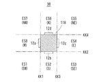
このように、物体検知システム1Bでは、無線送受信集合装置3Bに設けられた4つのRFタグ12a〜dの指向性によって、図7に示すように、その周囲の領域(システム領域)が8つの識別可能領域ES1〜8に画定される。
In this manner, in the
8つの識別可能領域ES1〜8とRFタグ12a〜dの識別情報DSであるTG1〜4の検知の有無との対応関係が、図8の領域判別テーブルTB2に示されている。領域判別テーブルTB2はメモリ73に記憶されている。
The correspondence relationship between the eight identifiable areas ES1 to 8 and the presence / absence of detection of TG1 to TG4 as identification information DS of the RF tags 12a to 12d is shown in the area determination table TB2 of FIG. The area determination table TB2 is stored in the
すなわち、図8の領域判別テーブルTB2によると、例えば、識別情報DSとして「TG1」「TG2」が検知されたときは、それに対応する識別可能領域は「ES1」であり、識別情報DSとして「TG2」のみが検知されたときは、それに対応する識別可能領域は「ES2」である。 That is, according to the area determination table TB2 of FIG. 8, for example, when “TG1” and “TG2” are detected as the identification information DS, the corresponding identifiable area is “ES1” and the identification information DS is “TG2”. ”Is detected, the identifiable area corresponding to it is“ ES2 ”.
また、図には示されていないが、各識別可能領域ES1〜8は、無線送受信集合装置3Bから見ると、それぞれ、南西、南、南東、東、北東、北、北西、西の方角に相当する。また、無線検知装置7が各識別可能領域ES1〜8の中に移動した場合に、そのときの無線検知装置7から見た無線送受信集合装置3Bの方角は、北東、北、北西、西、南西、南、南東、東となる。
Although not shown in the figure, the identifiable areas ES1 to ES8 correspond to the directions of southwest, south, southeast, east, northeast, north, northwest, and west, respectively, when viewed from the wireless transmission /
したがって、図6に示す例では、ユーザは、無線送受信集合装置3Bが北東の方角に存在することが分かる。
Therefore, in the example illustrated in FIG. 6, the user can understand that the radio transmission /
したがって、物体検知システム1Bによると、ユーザと一体に移動する無線検知装置7は、RFタグ12との通信によって得られた識別情報DSに基づいて、無線検知装置7つまり物体BTであるユーザが、いずれの識別可能領域ES1〜8に存在するのかを知ることができる。
Therefore, according to the
また、ユーザは、無線送受信集合装置3BとRFタグ12a〜dの取り付け方位が特定できる場合には、無線送受信集合装置3Bがどの方角にあるのか、または無線送受信集合装置3Bから見て自分はどの方角にいるのか、などを知ることができる。
Further, when the user can specify the mounting orientation of the wireless transmission /
このように、第2の実施形態の物体検知システム1Bによると、ユーザは、より特定された領域を自分の現在位置として知ることができる。また、自分の周囲または近くに存在する物体の位置やその物体についての情報などをより詳細に知ることができる。
Thus, according to the
つまり、物体検知システム1Bによると、簡単な構成によって物体BTの存在領域を検知することができる。
That is, according to the
また、RFタグ12との通信によって得られなかった識別情報DSをも用いて、いずれの識別可能領域ES1〜8に存在するのかまたは存在しないのかを判断することも可能である。
〔第3の実施形態〕
次に、第3の実施形態の物体検知システム1Cについて説明する。なお、物体検知システム1Cの図においては、物体BTおよびサーバなどの図示を省略する。以下同様である。
It is also possible to determine which of the identifiable areas ES1 to 8 exists or does not exist by using the identification information DS that is not obtained by communication with the
[Third Embodiment]
Next, an
図9および図10において、物体検知システム1Cは、無線送受信集合装置3Cおよび無線検知装置7などを備える。無線送受信集合装置3Cは、支持部材11Cおよび多数のRFタグ12を備える。
9 and 10, the
支持部材11Cは、遮蔽部材を用いて平面視が正八角形の柱状に形成されている。周囲の8つの面HMのそれぞれのほぼ中央部に、RFタグ12a〜hが1つずつ配置される。
11 C of support members are formed in the columnar shape of a regular octagon in planar view using the shielding member. One
なお、支持部材11Cの大きさは、無線検知装置7から見てRFタグ12(図9ではRFタグ12e〜g、図10ではRFタグ12d〜g)の存在を隠せる程度に十分な大きさとする。
Note that the size of the
支持部材11Cは、各面HMが、それぞれ所定の方角を向くように配置され、その姿勢または方向に基づいた種々の情報が、無線検知装置7などに記憶される。
The
図9および図10では、上方を北とした場合を示している。 9 and 10 show a case where the upper side is north.
各面HMへの接面などに基づいて境界面KKが設定される。各境界面KKの前方が、各RFタグ12a〜hについて指向性を持った検知可能領域EKである。この例では、8つの検知可能領域EKが設定される。これら検知可能領域EKに基づいて、多数の識別可能領域ES1,2,3…が画定される。 A boundary surface KK is set based on a contact surface to each surface HM. The front of each boundary surface KK is a detectable region EK having directivity with respect to each of the RF tags 12a to 12h. In this example, eight detectable areas EK are set. A large number of discriminable areas ES1, 2, 3,... Are defined based on these detectable areas EK.
なお、識別可能領域ESの画定に際しては、基本的には境界面KKまたは検知可能領域EKなどに基づいて幾何学的な区画を行うことでよいが、実際の電波の状態やRFタグ12の送受信の状態などに応じて修正すればよい。
In defining the identifiable area ES, it is basically possible to perform geometric division based on the boundary surface KK or the detectable area EK. However, the actual radio wave state and transmission / reception of the
図9に示す例では、無線検知装置7は、3つのRFタグ12a,b,cとの間でのみ送受信が可能である。無線検知装置7は、他のRFタグ12d〜hとは送受信できない。
In the example illustrated in FIG. 9, the
したがって、RFタグ12dの境界面KK4の後方でかつRFタグ12hの境界面KK8の後方であって、しかもRFタグ12aの境界面KK1およびRFタグ12cの境界面KK3よりも前方にある識別可能領域ES1が、物体存在領域EEとして検知される。
Therefore, the discriminable region is located behind the boundary surface KK4 of the
この例では、物体存在領域EEは、無線送受信集合装置3Cから見て南西の方角であり、例えば南から西へ45度の方向にあることが検知される。
In this example, it is detected that the object existence area EE is in the southwest direction when viewed from the wireless transmission /
また、図10に示す例では、無線検知装置7は、4つのRFタグ12a,b,c,hとの間でのみ送受信が可能である。無線検知装置7は、他のRFタグ12d〜gとは送受信できない。
In the example shown in FIG. 10, the
したがって、RFタグ12cの境界面KK3とRFタグ12hの境界面KK8との間にある識別可能領域ES5が、物体存在領域EEとして検知される。
Therefore, the identifiable area ES5 between the boundary surface KK3 of the
この例では、物体存在領域EEは、無線送受信集合装置3Cから見て西南西の方角であり、例えば真西から南へ45度の範囲の方向にあることが検知される。
In this example, it is detected that the object existence area EE is in the direction of west-southwest as viewed from the wireless transmission /
このようにして、ユーザは、無線検知装置7によって、現在いずれの識別可能領域ESに存在するのか、また無線送受信集合装置3Cがどの方角にあるのか、といったことを、高い精度で知ることができる。
In this way, the user can know, with high accuracy, which identifiable region ES is present and in which direction the wireless transmission /
なお、図9および図10において、各RFタグ12a〜hの位置にアンテナの部分のみを配置し、動作回路本体部分を支持部材11Cの内部に配置してもよい。その場合に、支持部材11Cの内部に配置する動作回路本体部分に、無線送受信集合装置3Cの全体または物体検知システム1の全体を管理するマネジャーの機能を持たせてもよい。
〔第4の実施形態〕
次に、第4の実施形態の物体検知システム1Dについて説明する。
9 and 10, only the antenna portion may be disposed at the position of each of the RF tags 12a to 12h, and the operation circuit main body portion may be disposed inside the
[Fourth Embodiment]
Next, an object detection system 1D according to a fourth embodiment will be described.
図11および図12において、物体検知システム1Dは、無線送受信集合装置3Dおよび無線検知装置7などを備える。無線送受信集合装置3Dは、支持部材11Dおよび多数のRFタグ12を備える。
11 and 12, the object detection system 1D includes a wireless transmission /
支持部材11Dは、遮蔽部材を用いて平面視が円形の柱状に形成されている。その周面に、多数のRFタグ12が配列されている。なお、支持部材11Dの大きさは、無線検知装置7から見て背面側のRFタグ12の存在を隠せる程度に十分な大きさとする。
The support member 11D is formed in a columnar shape with a circular plan view using a shielding member. A large number of RF tags 12 are arranged on the peripheral surface. Note that the size of the
これら多数のRFタグ12は、周方向の位置が互いに異なるので、支持部材11Dの表面への接面方向が互いに異なる。つまり、各RFタグ12ごとに、境界面KKの位置および方向が異なる。
Since many of these RF tags 12 have different positions in the circumferential direction, the directions of contact with the surface of the support member 11D are different from each other. That is, the position and direction of the boundary surface KK are different for each
図11および図12では、上方を北とした場合を描いている。 11 and 12 illustrate the case where the upper side is north.
各境界面KKの前方が、各RFタグ12について指向性を持った検知可能領域EKである。この例では、24個の検知可能領域EKが設定される。これら検知可能領域EKに基づいて、多数の識別可能領域ESが画定される。
The front of each boundary surface KK is a detectable region EK having directivity with respect to each
図11に示す例では、無線検知装置7は、RFタグ12uおよびRFタグ12vを含んでそれらの間にある11個のRFタグ12との間で送受信が可能である。無線検知装置7は、RFタグ12xからRFタグ12yまでの13個のRFタグ12とは送受信できない。
In the example illustrated in FIG. 11, the
したがって、RFタグ12uの境界面KK1とRFタグ12vの境界面KK2との間にある識別可能領域ES1が、物体存在領域EEとして検知される。
Therefore, an identifiable region ES1 between the boundary surface KK1 of the
図11に示す例では、物体存在領域EEは、無線送受信集合装置3Dから見て南西の方角であり、例えば南から西へ45度の方向にあることが高い精度で検知される。
In the example illustrated in FIG. 11, the object presence area EE is a southwest direction as viewed from the wireless transmission and
図12に示す例では、無線検知装置7が無線送受信集合装置3Dに近づいたため、送受信可能なRFタグ12は10個に減少している。
In the example shown in FIG. 12, since the
すなわち、無線検知装置7は、RFタグ12uおよびRFタグ12vを含んでそれらの間にある10個のRFタグ12との間で送受信が可能である。無線検知装置7は、RFタグ12xからRFタグ12yまでの14個のRFタグ12とは送受信できない。
That is, the
したがって、RFタグ12xの境界面KK3の後方でかつRFタグ12yの境界面KK4の後方であって、しかも、RFタグ12uの境界面KK1とRFタグ12vの境界面KK2との間にある識別可能領域ES1が、物体存在領域EEとして検知される。
Therefore, it is possible to distinguish between the boundary surface KK3 of the
図12に示す例では、物体存在領域EEは、無線送受信集合装置3Dに対する無線検知装置7の方向は図11の場合と同じであるが、無線検知装置7と無線送受信集合装置3Dとの間の距離が小さくなったことが検知される。
In the example shown in FIG. 12, the object presence area EE is the same as that in FIG. 11 in the direction of the
この例のように、支持部材11Dが円柱状である場合は、多角柱の場合のように面の数に規制されることなく、支持部材11Dの周面およびRFタグ12の大きさなどに応じて、多数のRFタグ12を配置することができる。RFタグ12をn個配置した場合に、(360/n)度の角度ごとに検知可能領域EKが設定され、これら検知可能領域EKの組み合わせによって多数の細かい識別可能領域ESを設定することができる。
As in this example, when the support member 11D is cylindrical, it is not limited by the number of surfaces as in the case of a polygonal column, and depends on the peripheral surface of the support member 11D, the size of the
そして、無線送受信集合装置3DにおけるいずれかのRFタグ12を、基準方向(例えば北の方向)に向けることにより、物体BTの物体存在領域EEを、その基準方向からの角度および方角で示すことができる。
Then, by pointing one of the RF tags 12 in the wireless transmission /
さらに、検知された識別可能領域ESに応じて、無線検知装置7と無線送受信集合装置3Dとの間のおまかな距離も検知される。これにより、無線検知装置7が無線送受信集合装置3Dに近づいたのか、または遠ざかったのか、ということも検知可能である。
Furthermore, a rough distance between the
また、検知されたRFタグ12についての接面方向などに基づいて、その距離の範囲を演算などによって求めることも可能である。
Further, based on the detected surface direction of the
また、無線検知装置7の検知方向、つまり電波の発射方向を基準方向(例えば北の方向)に向けた状態で、無線送受信集合装置3Dを支持部材11Dの中心軸を回転軸として回転させると、その回転速度に応じて、検知されるRFタグ12が順に切り替わる。
Further, when the detection direction of the
したがって、その場合に、無線検知装置7において、順に検知される識別情報DSについてデータ処理を行うことにより、無線送受信集合装置3Dの回転方向および回転速度を検知することができる。
Therefore, in this case, the
また、無線送受信集合装置3Dを支持する支持台が一体で回転している場合には、その支持台の回転の状態も同時に検知されることとなる。
〔第5の実施形態〕
次に、第5の実施形態の物体検知システム1Eについて説明する。
Moreover, when the support stand which supports radio | wireless transmission /
[Fifth Embodiment]
Next, an
図13において、物体検知システム1Eは、無線送受信集合装置3Eおよび無線検知装置7などを備える。無線送受信集合装置3Eは、支持部材11Eおよび多数のRFタグ12a〜hを備える。
In FIG. 13, an
支持部材11Eは、遮蔽部材を用いて平面視が8つの頂部を持つ星形に形成されている。つまり、支持部材11Eは、その表面が面HMを凹凸に組み合わせた形状である。RFタグ12は、星形を形成する凸部と凸部との間の各凹部に1つずつ取り付けられる。
The
図13に示す支持部材11Eでは、星形を形成する各面HMによって境界面KKが設定され、検知可能領域EKが設定される。検知可能領域EKに基づいて、多数の識別可能領域ESが画定される。
In the
なお、支持部材11Eの星形の長径の大きさは、無線検知装置7から見て背面側のRFタグ12の存在を隠せる程度に十分な大きさとする。
In addition, the size of the major axis of the star shape of the
図13に示す例では、無線検知装置7は、RFタグ12aのみと送受信が可能である。したがって、RFタグ12aの両側の面HMによる境界面KK1,2の間にあって、かつ、境界面KK3の後方にありかつ境界面KK4の後方にある識別可能領域ES1が、物体存在領域EEとして検知される。
In the example illustrated in FIG. 13, the
図13に示す物体検知システム1Eでは、各RFタグ12の指向性および独立性が高められている。これにより、RFタグ12の間の混信が低減され、識別可能領域ESや方向の検知が容易となる。
〔第6の実施形態〕
次に、第6の実施形態の物体検知システム1Fについて説明する。
In the
[Sixth Embodiment]
Next, an
図14において、物体検知システム1Fは、無線送受信集合装置3Fおよび無線検知装置7などを備える。無線送受信集合装置3Fは、支持部材11Fおよび多数のRFタグ12a〜hを備える。
In FIG. 14, the
支持部材11Fは、遮蔽部材を用いて平面視が8つの頂部を持つ星形に形成されている。つまり、支持部材11Fは、凸部および凹部に曲面が形成され、凸面と凹面とが組み合わされた形状である。RFタグ12は、各凹部に1つずつ取り付けられる。
The
なお、支持部材11Fの星形の長径の大きさは、無線検知装置7から見て背面側のRFタグ12の存在を隠せる程度に十分な大きさとする。
In addition, the size of the major axis of the star shape of the
図14に示す支持部材11Fでは、星形を形成する各面HMによって境界面KKが設定され、検知可能領域EKが設定される。検知可能領域EKに基づいて、多数の識別可能領域ESが画定される。
In the
図14に示す例では、無線検知装置7は、RFタグ12aのみとの間で送受信が可能である。したがって、RFタグ12aの両側の面HMによる境界面KK1,2の間にあって、かつ、境界面KK3の後方にありかつ境界面KK4の後方にある識別可能領域ES1が、物体存在領域EEとして検知される。
In the example illustrated in FIG. 14, the
図14に示す物体検知システム1Eにおいても、各RFタグ12の指向性および独立性が高められている。これにより、RFタグ12の間の混信が低減され、識別可能領域ESや方向の検知が容易となる。
〔第7の実施形態〕
次に、第7の実施形態の物体検知システム1Gについて説明する。
Also in the
[Seventh Embodiment]
Next, an
上に述べた第1〜第6の実施形態では、各物体検知システム1、1B〜Fによって2次元的な面内における物体BTの位置を検知した。これに対し、第7の実施形態では、支持部材11Gを球状とした。これにより、支持部材11Gに対する無線検知装置7の位置に依存することなく、全方位からRFタグ12を検知でき、3次元的な空間内における物体BTの位置を検知することができる。
In the first to sixth embodiments described above, the position of the object BT in the two-dimensional plane is detected by the
すなわち、図15において、物体検知システム1Gは、無線送受信集合装置3Gおよび無線検知装置7などを備える。無線送受信集合装置3Gは、支持部材11Gおよび多数のRFタグ12を備える。
That is, in FIG. 15, the
支持部材11Gは、遮蔽部材を用いて球の形状に形成されている。球の表面に、多数のRFタグ12が配列されている。
The
なお、支持部材11Gの大きさは、無線検知装置7から見て背面側のRFタグ12の存在を隠せる程度に十分な大きさとする。
Note that the size of the
これら多数のRFタグ12は、表面上の位置が互いに異なるので、支持部材11Gの表面への接面方向が互いに異なる。つまり、各RFタグ12ごとに、境界面KKの位置および方向が異なる。
Since these many RF tags 12 have different positions on the surface, the directions of contact with the surface of the
各境界面KKの前方が、各RFタグ12について指向性を持った検知可能領域EKである。これら検知可能領域EKに基づいて、多数の識別可能領域ESが画定される。
The front of each boundary surface KK is a detectable region EK having directivity with respect to each
図16をも参照して、無線検知装置7は、RFタグ12uおよびRFタグ12vを含んだ仮想円周上にあるRFタグ12およびそれよりも無線検知装置7に近い側のRFタグ12との間で送受信が可能である。
Referring also to FIG. 16, the
したがって、RFタグ12uおよびRFタグ12vを含んだ仮想円周上にあるRFタグ12の各境界面KK1〜2よりも前方にあり、かつそれらのRFタグ12よりも1つずつ奥側にあるRFタグ12の各境界面KK3〜4の後方にある識別可能領域ES1が、物体存在領域EEとして検知される。
Therefore, RF which is ahead of each boundary surface KK1-2 of the
つまり、各境界面KK1〜2よりも前方により形成される円錐部分と、各境界面KK3〜4の後方によって形成される円錐部分との積集合が、識別可能領域ES1であり、これが物体存在領域EEとして検知される。 That is, a product set of a conical portion formed forward of each boundary surface KK1-2 and a conical portion formed behind each boundary surface KK3-4 is an identifiable region ES1, which is an object existence region. Detected as EE.
図15に示す物体検知システム1Gによると、無線送受信集合装置3Gによって3次元の空間内に多数の識別可能領域ESが画定される。無線検知装置7は、RFタグ12からの識別情報DSに基づいて、3次元的に識別される領域のうちのいずれの領域に物体BTが存在するかを検知することができる。
According to the
なお、支持部材11Gには、支持台21が取り付けられており、支持台21によって適当なフレームなどに取り付けられる。
〔球形の支持部材の構造の説明〕
次に、無線送受信集合装置3Gの構造について、その一例を説明する。
A
[Description of the structure of the spherical support member]
Next, an example of the structure of the radio transmission /
ここで説明する無線送受信集合装置3Gの構造によると、複数のRFタグ12は、支持部材11Gの表面に設けられた多数の凹部のそれぞれにおいて、電磁波を透過させる非遮蔽部材を介して支持されるように配置されまたは埋め込まれている。
According to the structure of the wireless transmission /
すなわち、図17に示すように、無線送受信集合装置3Gに用いられる支持部材11Gは、球形であり、その表面に外形が円形で凹曲面状の多数のディンプル(窪み)DPが形成されている。各ディンプルDPの底部中央に、RFタグ12が1つずつ配置されている。
That is, as shown in FIG. 17, the
なお、ディンプルDPの外形は、円形以外に、正五角柱、正六角柱、正八角柱などの正多角形、または台形など、種々の形状とすることが可能である。 In addition to the circular shape, the dimple DP may have various shapes such as a regular polygon such as a regular pentagonal column, a regular hexagonal column, and a regular octagonal column, or a trapezoidal shape.
図18に示すように、支持部材11Gは、中心部24、電波吸収層25、およびソケット部材22などからなる。
As shown in FIG. 18, the
中心部24は、遮蔽部材または非遮蔽部材を用いて、小球状に形成されていている。
The
電波吸収層25は、遮蔽部材つまり電波不透過部材を用いて、中心部24を覆うように球面状に形成されている。電波吸収層25は、RFタグ12から発射される電波のうち、電波吸収層25の表面に向かう成分を吸収しまたは反射し、RFタグ12が発射する電波に指向性を与える。
The radio
ソケット部材22は、遮蔽部材つまり電波不透過部材を用いて、電波吸収層25を取り囲むように球面状に形成されている。ソケット部材22には、円錐台状の多数の孔22aが設けられている。
The
各孔22aには、非遮蔽部材つまり電波透過部材を用いて形成された円錐台状の保持部材23が装着されている。
A
保持部材23の径が大きい方の端面は、凹曲面状に窪んでおり、これが上に述べたディンプルDPとなっている。ディンプルDPに配置されたRFタグ12は、ソケット部材22の表面から突出することなく、支持部材11Gに埋め込まれた状態となっている。
The end surface having the larger diameter of the holding
ソケット部材22によって、周囲の環境からRFタグ12にノイズ電波が入ることが防止され、またRFタグ12に必要な指向性が与えられる。
The
保持部材23によって、RFタグ12とソケット部材22および電波吸収層25とが密着することなく、それらの間に適当な距離が保たれる。これにより、RFタグ12の感度が低下しないように維持される。
The holding
このように、支持部材11Gは、概ね、ゴルフボールを大きくしたような形状である。電波吸収層25およびソケット部材22の内径、外径、厚さなどは、RFタグ12に対して必要な指向性を与えることができる程度とされている。
Thus, the
なお、ソケット部材22に設けられる孔22aの個数、つまり支持部材11Gに配置されるRFタグ12の個数は、多いほど精度の高い検知が可能である。したがって、孔22aの内径つまり保持部材23の外径は、必要な精度を得るための個数が確保される程度の小さな値に設定される。
It should be noted that the higher the number of holes 22a provided in the
なお、保持部材23や中心部24などに用いる非遮蔽部材として、例えば、プラスチック、発泡スチロール、木質、紙質などの非導電性物質を用いることが可能である。また、無線送受信集合装置3を設置する場合に応じて、対候性、耐熱性、対薬品性、または耐水性などを考慮した耐久性のある素材を用いることが好ましい。
In addition, as a non-shielding member used for the holding
また、保持部材23の中に気泡などを入れたり、またはRFタグ12を単に支持するだけの中空構造としてもよい。これにより、支持部材11Gの軽量化を図ることができ、またRFタグ12の感度が低下しないように維持される効果も期待できる。
〔第8の実施形態〕
次に、第8の実施形態の物体検知システム1Hについて説明する。
Moreover, it is good also as a hollow structure which puts a bubble etc. in the holding
[Eighth Embodiment]
Next, an
上に述べた第1〜第7の各実施形態では、無線送受信集合装置3、3B〜Gが1個のみである場合について説明した。しかし、1つの物体検知システムにおいて、無線送受信集合装置3、3B〜Gを複数個配置することができる。
In the first to seventh embodiments described above, the case where there is only one radio transmission /
その例として、第8の実施形態では、図11および図12に示す無線送受信集合装置3Dを複数個用いた物体検知システム1Hを説明する。
As an example, in the eighth embodiment, an
図19において、物体検知システム1Hでは、4つの無線送受信集合装置3Da〜dが、四辺形の4つの頂点の位置に配置されている。
In FIG. 19, in the
これらの無線送受信集合装置3Da〜dは、いずれも図11および図12において説明した無線送受信集合装置3Dと同じ構成のものである。
These radio transmission / reception aggregation devices 3Da to 3d all have the same configuration as the radio transmission /
物体検知システム1Hにおいて、各無線送受信集合装置3Da〜dのシステム座標系における位置、姿勢、方角などが認識されており、それらの情報が無線検知装置7およびサーバ8などに登録されている。
In the
したがって、システム領域において、これらの無線送受信集合装置3Da〜dによって多数の識別可能領域ESが画定されている。1つの無線送受信集合装置3Dを用いた場合と比べて、より多くの細かい識別可能領域ESが画定されるので、物体存在領域EEの検知精度を高めることができる。
Accordingly, in the system area, a large number of identifiable areas ES are defined by these wireless transmission / reception aggregation devices 3Da to 3d. Compared with the case where one radio transmission /
物体検知システム1Hにおいては、無線検知装置7をいずれの方向に向けた場合でも、無線送受信集合装置3Da〜dのいずれかがその電波を受信し、物体存在領域EEを検知することができる。
In the
つまり、無線検知装置7を2次元的な面内において回転させ、各無線送受信集合装置3Da〜dに配置された複数のRFタグ12から受信した識別情報DSに基づいて、2次元的な面内における物体BTの位置を検知することができる。
That is, the
例えば、図19に示す状態で、無線検知装置7から電波を発射させながら、電波の発射方向が変わるように無線検知装置7をその場で回転させる。その間において、4つの無線送受信集合装置3Da〜dとの送受信が順次行われ、それぞれの識別可能領域ESが検知される。それらの検知結果を総合することにより、無線検知装置7についての物体存在領域EEがより一層高い精度で検知される。
For example, in the state shown in FIG. 19, the
なお、無線検知装置7を回転させた場合において、4つ全ての無線送受信集合装置3Da〜dとの間で送受信が行われなくてもよい。送受信が行われた無線送受信集合装置3Dのみの検知結果を用いて最終的な識別可能領域ESを特定すればよい。
When the
また、配置する無線送受信集合装置3Da〜dの位置は、四辺形の4つの頂点の位置でなく、任意の位置にまたは任意の分布で配置することが可能である。 Further, the positions of the radio transmission / reception aggregation devices 3Da to 3d to be arranged can be arranged at arbitrary positions or in an arbitrary distribution, not at the positions of the four apexes of the quadrilateral.
なお、4つの無線送受信集合装置3Da〜dによる検知結果の総合処理は、無線検知装置7で行ってもよく、またサーバ8で行ってもよい。
The comprehensive processing of detection results by the four wireless transmission / reception aggregation devices 3Da to 3d may be performed by the
図19に示す物体検知システム1Hでは、物体BTを例えばフォークリフトまたは自動走行ロボットなどとし、それらに無線検知装置7を装着した場合を想定することができる。この場合に、フォークリフトまたは自動走行ロボットは、無線検知装置7によって現在地および移動方向を確認することができ、作業に必要な動作を行うことが可能となる。
〔第9の実施形態〕
次に、第9の実施形態の物体検知システム1Jについて説明する。
In the
[Ninth Embodiment]
Next, an
第9の実施形態の物体検知システム1Jでは、さらに多数の無線送受信集合装置3Dが配置され、複数の無線検知装置7が同時に検知動作を行えるようになっている。
In the
すなわち、図20に示す物体検知システム1Jにおいて、システム領域に12個の無線送受信集合装置3Dがマトリクス状に配置されている。システム領域内で、3つの無線検知装置7a〜cが使用され、それらが独立して検知動作を行っている。
That is, in the
各無線検知装置7a〜cは、それぞれの近辺に配置された1つまたは複数の無線送受信集合装置3Dとの間で送受信を行い、それぞれ正確な物体存在領域EEを検知する。1つの無線送受信集合装置3Dが複数の無線検知装置7と同時に送受信を行うことも可能である。各無線検知装置7a〜cによる検知結果は、サーバ8に送信され、サーバ8において総合的な判断および処理が行われる。
Each of the
例えば、サーバ8において、各無線検知装置7a〜cを携帯した作業者(ユーザ)に対し、さらに移動すべき方向または目標などを指示する。また、それら作業者に対し、それぞれの位置において行うべき作業を指示する。
For example, the
このように、第9の実施形態の物体検知システム1Jによると、例えばサーバ8を操作する管理者は、複数の作業者の現在位置をリアルタイムで把握し、必要な指示を与えることができる。
Thus, according to the
なお、作業者に代えて、フォークリフトまたは自動走行ロボットなどであってもよい。無線送受信集合装置3Dおよび無線検知装置7の個数、配置形態などは、任意のものとすることができる。
Note that a forklift or an automatic traveling robot may be used instead of the worker. The number of radio transmission /
このような物体検知システム1Jは、例えば、工場、倉庫、プラント、競技場、博覧会場、イベント会場、農園、公園、山岳地帯、都市空間などにおいて利用することができる。
〔第10の実施形態〕
次に、第10の実施形態の物体検知システム1Kについて説明する。
Such an
[Tenth embodiment]
Next, an
第9の実施形態の物体検知システム1Jでは、複数の無線送受信集合装置3Dが平面的に配置されていたが、第10の実施形態の物体検知システム1Kでは、多数の図15に示す無線送受信集合装置3Gが、システム領域の空間内に立体的に配置されている。
In the
すなわち、図21に示す物体検知システム1Kにおいて、マトリクス状に配置された9個の無線送受信集合装置3Gがさらに3層に立体的に配置されている。例えば、下層の無線送受信集合装置3Gは1階の高さ位置に、中層の無線送受信集合装置3Gは2階の高さ位置に、上層の無線送受信集合装置3Gは3階の高さ位置に、それぞれ配置される。
That is, in the
システム領域内において、2つの無線検知装置7a〜bが使用され、それらが独立して検知動作を行っている。
In the system area, two
各無線検知装置7a〜bは、それぞれの近辺に配置された1つまたは複数の無線送受信集合装置3Gとの間で送受信を行い、それぞれ正確な物体存在領域EEを検知する。図に示す例では、各無線検知装置7a〜bは、それぞれ8つの無線送受信集合装置3Gとの間で送受信を行い、それぞれの物体存在領域EEを検知している。
Each of the
各無線検知装置7a〜bによる検知結果は、サーバ8に送信され、サーバ8において総合的な判断および処理が行われる。
The detection result by each of the
つまり、例えば無線検知装置7aを3次元的な空間内において回転させ、各無線送受信集合装置3Gに配置された複数のRFタグ12の識別情報DSに基づいて、3次元的な面内における物体BTの位置を検知することができる。
That is, for example, the
例えば、サーバ8において、各無線検知装置7a〜bを携帯した作業者(ユーザ)に対し、さらに移動すべき方向または目標などを指示する。例えば、立体倉庫などにおいて在庫品を取りにいった作業者に対して、「そこからさらに1m上へ上がれ」などと指示をする。
For example, the
また、作業者に対しそれぞれの位置において行うべき作業を指示する。例えば、化学プラントのメンテナンスを行う作業者に対して、「50cm前方にあるバルブを締めてその右横30cmにあるバルブを開けよ」などと指示する。 Also, the operator is instructed on the work to be performed at each position. For example, an operator who performs maintenance of the chemical plant is instructed to “tighten the valve in front of 50 cm and open the valve 30 cm to the right”.
このように、第10の実施形態の物体検知システム1Kによると、例えばサーバ8を操作する管理者は、複数の作業者の現在位置をリアルタイムで把握し、必要な指示を与えることができる。
Thus, according to the
なお、各無線検知装置7a〜bは、1つの無線送受信集合装置3Gとの間で送受信を行うことによってもその物体存在領域EEを検知することが可能である。しかし、複数の無線送受信集合装置3G、例えば3つ以上の無線送受信集合装置3Gとの間で送受信を行うことにより、より一層高い精度で物体存在領域EEを検知することができる。
〔第11の実施形態〕
次に、第11の実施形態の物体検知システム1Lについて説明する。
Each of the
[Eleventh embodiment]
Next, an
第11の実施形態では、支持部材11Lが回転楕円体である。ここでは支持部材11Lが特に長球である場合について説明する。偏球の回転楕円体については次の第12の実施形態で説明する。
In the eleventh embodiment, the
すなわち、図22に示すように、物体検知システム1Lは、無線送受信集合装置3Lおよび無線検知装置7などを備える。無線送受信集合装置3Lは、支持部材11Lおよび多数のRFタグ12を備える。
That is, as shown in FIG. 22, the
支持部材11Lは、遮蔽部材を用いて長球の形状に形成されている。長球は、2つの同一長さの短半径aと1つの長半径bを持つ。図22に示す支持部材11Lは、3次元座標内において長半径がx軸上に一致するように配置されている。なお、ここでは水平方向をy軸、鉛直方向をz軸とする。
The
支持部材11Lの表面に、多数のRFタグ12が配列されている。これら多数のRFタグ12について、それぞれ境界面KKが規定され、検知可能領域EKが設定される。それらの検知可能領域EKに基づいて、多数の識別可能領域ESが画定される。
A number of RF tags 12 are arranged on the surface of the
図23をも参照して、無線検知装置7は、RFタグ12uおよびRFタグ12vを含んだ仮想円周上にあるRFタグ12およびそれよりも無線検知装置7に近い側のRFタグ12との間で送受信が可能である。
Referring also to FIG. 23, the
したがって、RFタグ12uおよびRFタグ12vを含んだ仮想円周上にあるRFタグ12の各境界面KK1〜2よりも前方にあり、かつそれらのRFタグ12よりも1つずつ奥側にあるRFタグ12の各境界面KK3〜4の後方にある識別可能領域ES1が、物体存在領域EEとして検知される。
Therefore, RF which is ahead of each boundary surface KK1-2 of the
また、検知されたRFタグ12についての接面方向などに基づいて、無線検知装置7と無線送受信集合装置3Lとの距離L1が求められる。距離L1を求める方法について、その例を図23によって説明する。
Further, the distance L1 between the
図23には、図22の支持部材11Lを、水平面つまりx軸およびy軸を含む平面(水平面)で切断した断面(水平断面)DMAが示されている。図23に示す水平断面DMAの形状は楕円であり、長軸がx軸、短軸がy軸とそれぞれ重なっている。
FIG. 23 shows a cross section (horizontal cross section) DMA obtained by cutting the
なお、無線検知装置7は、無線送受信集合装置3Lの左側にあるものとする。つまり、無線検知装置7は、xy座標面と同じ面内にあり、かつxy座標面における第2象限および第3象限の範囲内にあるものとする。
The
さて、図23に示される水平断面DMAの楕円の式を、次の(1)式で表すものとする。 Now, the equation of the ellipse of the horizontal section DMA shown in FIG. 23 is represented by the following equation (1).
ax2 +by2 =1 ……(1)
支持部材11Lの周面に取り付けるRFタグ12の位置(x,y)において、上の(1)式で示される楕円に対する接線の式を、傾きをm、x切片をnとして、次の(2)式で表す。
ax 2 + by 2 = 1 (1)
At the position (x, y) of the
x=my+n ……(2)
これらの接線は、各RFタグ12の検知可能領域EKについての境界線(検知境界線)であり、上に述べた各RFタグ12についての境界面KKに対応する。
x = my + n (2)
These tangents are boundary lines (detection boundary lines) for the detectable regions EK of the respective RF tags 12 and correspond to the boundary surfaces KK for the respective RF tags 12 described above.
上の(2)式におけるx切片nは、x軸上に置かれた無線検知装置7の位置を示す。つまり、回転楕円体である支持部材11Lの中心点を原点とするxy座標上で、無線検知装置7は、x=nの位置に存在することになる。
The x-intercept n in the above equation (2) indicates the position of the
x切片nができるだけ均等な間隔で求まるように、支持部材11Lの水平断面DMAである楕円の形状パラメータa,b、およびRFタグ12の取り付け位置(x,y)を決定する。これにより、RFタグ12のうちで、無線検知装置7によって検知されたRFタグ12と検知されなかったRFタグ12とが決まると、無線検知装置7と無線送受信集合装置3Lとの間の距離L1またはその範囲が、容易に精密に求められる。
The ellipse shape parameters a and b, which are the horizontal section DMA of the
図24に、a=1、b=100とした場合の、x切片n、傾きm、およびRFタグ12の取り付け位置(x,y)の関係の具体例が示されている。
FIG. 24 shows a specific example of the relationship between the x intercept n, the inclination m, and the attachment position (x, y) of the
図23において、無線検知装置7は、n=−1からn=−5の範囲の整数で表される位置にある場合が示されている。それぞれの位置nに対応するRFタグ12の取り付け位置のx座標は、x=1/nである。
In FIG. 23, the case where the radio |
図23において、水平断面DMA内に記載された縦線(縦線群)は、x=1/n(n=−2、−3、−4、−5)で示される直線であり、これら縦線が楕円と交わる点にRFタグ12が取り付けられる。また、これら縦線が楕円と交わる点における接線、つまり、x=my+n(n=−2、−3、−4、−5)で示される直線が、境界線(KK)として示されている。
In FIG. 23, vertical lines (vertical line group) described in the horizontal section DMA are straight lines represented by x = 1 / n (n = −2, −3, −4, −5), and these vertical lines are The
なお、図23において、図を分かりやすくするために、y軸方向の縮尺がx軸方向に比べて5倍引き伸ばして描かれている。 In FIG. 23, the scale in the y-axis direction is drawn five times larger than that in the x-axis direction for easy understanding.
例えば、無線検知装置7によって、x=−1/4で示される縦線上にあるRFタグ12が検知され、x=−1/5で示される縦線上にあるRFタグ12が検知されなかった場合には、無線検知装置7は、x=−4からx=−5までの間に存在することとなる。
For example, when the
このように、無線検知装置7により検知されたRFタグ12に応じて、無線検知装置7と無線検知装置7と無線送受信集合装置3Lとの間の距離L1の範囲が精密に求められる。
Thus, according to the
図22に示す物体検知システム1Lによると、形状が回転楕円体である支持部材11Lを用いることにより、無線検知装置7までの距離L1(またはその範囲)、つまり無線検知装置7の位置を、精密に検知することができる。
According to the
また、支持部材11Lの水平断面DMAの楕円の形状パラメータa、bおよびRFタグ12の取り付け位置(x,y)を適当なものに調整することによって、無線検知装置7と無線送受信集合装置3Lとの間の距離L1の必要計測精度に応じた適切な物体検知システム1Lを設計することができる。
Further, by adjusting the shape parameters a and b of the ellipse of the horizontal section DMA of the
なお、無線検知装置7の距離の計測に際し、支持部材11Lのx軸を無線検知装置7の方に向ける必要があるが、無線検知装置7の方向を検知するために、先に説明したような種々の無線送受信集合装置3を用いることができる。
In measuring the distance of the
例えば、図11に示した無線送受信集合装置3Dを用いて無線検知装置7の方向を検知する。無線送受信集合装置3Lを、その向きを変更できるように回転可能に取り付けておき、無線送受信集合装置3Dを用いて検知された方向に無線送受信集合装置3Lのx軸を向ける。無線送受信集合装置3Lによって、無線検知装置7までの距離L1、つまり無線検知装置7の位置を精密に計測することができる。
For example, the direction of the
また、複数の無線送受信集合装置3Lを、同じ場所に、互いのx軸の方向が異なるように設けておく。そして、無線検知装置7が、それら複数の無線送受信集合装置3Lに対して同時に検知を行う。このようにすると、各無線送受信集合装置3Lに対して計測された無線検知装置7までの距離を組み合わせることにより、無線検知装置7の方向と位置を、精密に検知しまたは計測することができる。
Also, a plurality of radio transmission /
なお、ここでは、支持部材11Lが回転楕円体である場合について説明したが、支持部材11Lが楕円柱である場合においても、2次元的な面内における物体BTの方向および距離を精密に検知することができる。
Although the case where the
すなわち、支持部材11Lが、その水平断面DMAが図23に示すような楕円である楕円柱であった場合に、2次元的な面内において物体BTの方向および距離を精密に検知し、その位置を精密に特定することが可能である。
That is, when the
ところで、図23では、無線検知装置7が支持部材11Lのx軸線上にあるものとして説明したが、x軸線上からずれている場合であっても、無線検知装置7と無線送受信集合装置3Lとの間の距離L1を精密に計測することができる。
By the way, in FIG. 23, the
すなわち、上に述べたように、無線検知装置7が支持部材11Lのx軸線上にある場合には、検知されるRFタグ12の集合(検知RFタグ群)と検知されないRFタグ12の集合(非検知RFタグ群)との境界部分はほぼ円形になる。
That is, as described above, when the
しかし、無線検知装置7が支持部材11Lのx軸線上からずれた場合には、その境界部分は円形とはならず、図25に示すように楕円形に近い形状となる。
However, when the
すなわち、図25において、境界部分において無線検知装置7により検知されたRFタグ12の集合である検知RFタグ群GKが示されている。支持部材11Lは、境界部分において断面され、境界部分断面DMBとして示されている。
That is, FIG. 25 shows a detection RF tag group GK that is a set of RF tags 12 detected by the
境界部分断面DMBの形状は、ほぼ楕円であり、長軸JKNと短軸JKTを有する。回転楕円体である支持部材11Lの中心点と無線検知装置7とを結ぶ直線とx軸とを含む平面の方向が、長軸JKNの方向であり、その平面に垂直な平面の方向が短軸JKTの方向である。
The shape of the boundary partial cross section DMB is substantially elliptical, and has a major axis JKN and a minor axis JKT. The direction of the plane including the straight line connecting the center point of the
図25では、横方向が長軸JKNであり縦方向が短軸JKTである例が示されているが、無線検知装置7の位置によっては、縦方向が長軸JKNとなり横方向が短軸JKTとなることがあり、また、長軸JKNと短軸JKTとが互いに斜めに傾斜角を持って交わることもある。
FIG. 25 shows an example in which the horizontal direction is the long axis JKN and the vertical direction is the short axis JKT. However, depending on the position of the
また、上に述べたように無線検知装置7がx軸上にある場合は、長軸JKNと短軸JKTとは同じ長さとなるが、無線検知装置7がx軸上から離れるにしたがって、長軸JKNと短軸JKTとの長さの差が増大し、かつ短軸JKTが中心から偏心するという傾向がある。
Further, as described above, when the
図25において、長軸JKNおよび短軸JKTの各端部に位置する4つのRFタグ12a〜dを含む平面(境界部分断面DMB)に対して垂直な法線HS上に、無線検知装置7が存在する。したがって、法線HSは、無線検知装置7についての存在可能線ということができる。
In FIG. 25, the
また、距離L1については、短軸JKTの各端部に位置する2つのRFタグ12a〜bを用いて、図23の場合と同様の手続きによって求めることができる。すなわち、その2つのRFタグ12a〜bについての境界線(KK)を導出し、導出した境界線(KK)と法線HSとの交点に無線検知装置7が存在するとして、その間の距離L1を求めることができる。
〔第12の実施形態〕
次に、第12の実施形態の物体検知システム1Mについて説明する。
Further, the distance L1 can be obtained by a procedure similar to the case of FIG. 23 using the two
[Twelfth embodiment]
Next, an
第12の実施形態では、支持部材11Mが偏球の回転楕円体である。
In the twelfth embodiment, the
すなわち、図26に示すように、物体検知システム1Kは、無線送受信集合装置3Kおよび無線検知装置7などを備える。無線送受信集合装置3Kは、支持部材11Kおよび多数のRFタグ12を備える。
That is, as shown in FIG. 26, the
支持部材1KLは、遮蔽部材を用いて偏球の形状に形成されている。偏球は、1つの短半径aと2つの同一長さの長半径bとを持つ。 The support member 1KL is formed in an oblate shape using a shielding member. The oblate sphere has one short radius a and two long radii b of the same length.
支持部材11Kの表面に、多数のRFタグ12が配列されている。これら多数のRFタグ12について、それぞれ境界面KKが規定され、検知可能領域EKが設定される。それらの検知可能領域EKに基づいて、多数の識別可能領域ESが画定される。 A number of RF tags 12 are arranged on the surface of the support member 11K. A boundary surface KK is defined for each of the large number of RF tags 12, and a detectable region EK is set. A large number of discriminable areas ES are defined based on these detectable areas EK.
図27に、図25と同様に境界部分において無線検知装置7により検知されたRFタグ12の集合である検知RFタグ群GKが示されている。支持部材11Kは、境界部分において断面され、境界部分断面DMBとして示されている。
FIG. 27 shows a detection RF tag group GK that is a set of RF tags 12 detected by the
境界部分断面DMBの形状は、ほぼ楕円であり、長軸JKNと短軸JKTを有する。x軸とy軸とを含む平面の方向が長軸JKNの方向であり、その平面に垂直で回転楕円体である支持部材11Lの中心点と無線検知装置7とを結ぶ直線を含む平面の方向が短軸JKTの方向である。
The shape of the boundary partial cross section DMB is substantially elliptical, and has a major axis JKN and a minor axis JKT. The direction of the plane including the x-axis and the y-axis is the direction of the major axis JKN, and the direction of the plane including a straight line that connects the center point of the
また、無線検知装置7がx軸およびy軸を含む平面上にある場合は、短軸JKTの中心は長軸JKN上にあるが、無線検知装置7がx軸およびy軸を含む平面から離れるにしたがって、短軸JKTの中心は長軸JKNから離れていくという傾向がある。その場合に、大まかには西洋梨の形状に近くなるといえる。
When the
図27において、長軸JKNおよび短軸JKTの各端部に位置する4つのRFタグ12a〜dを含む平面(境界部分断面DMB)に対して垂直な法線HS上に、無線検知装置7が存在する。
In FIG. 27, the
また、距離L1については、第11の実施形態と同様に、短軸JKTの各端部に位置する2つのRFタグ12a〜bを用いて、図23の場合と同様の手続きによって求めることができる。すなわち、その2つのRFタグ12a〜bについての境界線(KK)を導出し、導出した境界線(KK)と法線HSとの交点に無線検知装置7が存在するとして、その間の距離L1を求めることができる。
Further, the distance L1 can be obtained by the same procedure as in the case of FIG. 23 using the two
なお、無線検知装置7が、x軸およびy軸を含む平面上になくその平面の上方または下方に変位している場合は、2つのRFタグ12a〜bについての境界線(KK)は対称にはならない。しかし、その場合に、短軸JKTの各端部における支持部材11Kへの接面と法線HSとの交点から、距離L1を求めることができる。
〔第13の実施形態〕
次に、第13の実施形態の物体検知システム1Nについて説明する。
Note that when the
[Thirteenth embodiment]
Next, an
第13の実施形態では、無線送受信集合装置3Nの支持部材11Nが、その内部または表面に空隙を有した構造となっている。つまり、支持部材11Nは、遮蔽部材である電波不透過部材を用いて形成されるが、その遮蔽部材が均一組成で形成されていない。 In the thirteenth embodiment, the support member 11N of the wireless transmission and reception aggregation device 3N has a structure having a gap inside or on the surface thereof. That is, the support member 11N is formed using a radio wave opaque member that is a shielding member, but the shielding member is not formed with a uniform composition.
図28(a)に示す支持部材11Naは、遮蔽部材を用いて形成された複数のブロックBKが組み合わされて構成される。各ブロックBKの周面は平面ではなく、互いに入り組んだ曲面状であるため、電波が内部に侵入しても裏側にまでは到達しない。 The support member 11Na shown in FIG. 28A is configured by combining a plurality of blocks BK formed using a shielding member. Since the peripheral surface of each block BK is not a flat surface but a curved surface that is intricate with each other, even if radio waves enter the inside, they do not reach the back side.
図28(b)に示す支持部材11Nbは、遮蔽部材が網目構造に形成されている。網目の大きさは、使用する電波の波長に対応して内部に電波が侵入できない大きさであり、電波が内部に侵入しても裏側にまでは到達しない。 In the support member 11Nb shown in FIG. 28B, the shielding member is formed in a mesh structure. The size of the mesh is such that the radio wave cannot enter the inside corresponding to the wavelength of the radio wave used, and even if the radio wave enters the inside, it does not reach the back side.
これら支持部材11Na,bによると、その全体を遮蔽部材で均一な組成で形成した場合と比べて、重量を軽くすることができるにも係わらず、それと同等の電波遮蔽効果を得ることができる。 According to these support members 11Na and b, the radio wave shielding effect equivalent to that can be obtained although the weight can be reduced compared with the case where the whole is formed with a uniform composition by the shielding member.
このように、無線送受信集合装置3Nの支持部材11Nとして、内部に隙間のあるもの、メシュによって形成されたものなど、均一で密なもの以外の種々の構造とすることが可能である。
〔第14の実施形態〕
次に、第14の実施形態の物体検知システム1Pについて説明する。
As described above, the support member 11N of the wireless transmission / reception aggregation device 3N can have various structures other than a uniform and dense structure such as a gap inside and a support formed by a mesh.
[Fourteenth embodiment]
Next, an
上の各実施形態では、無線送受信手段としてRFタグ12それ自体を用いた。しかしここに説明する第14の実施形態では、無線送受信集合装置3PにRFタグ12の機能が分割されて配置される。
In the above embodiments, the
つまり、第14の実施形態の無線送受信集合装置3Pでは、RFタグ12の機能をアンテナと動作回路本体部分とに分離し、かつ、複数の動作回路本体部分の機能を1つのRFID集中機構に集約し、RFID集中機構に複数のアンテナを接続する。
That is, in the wireless transmission and
図29において、正六角柱の形状を有した支持部材11Pに、集積型RFタグ12Pが設けられた例が示されている。図29(a)は外観を示す斜視図、図29(b)は水平断面図である。
FIG. 29 shows an example in which an integrated RF tag 12P is provided on a
図29(a)に示すように、支持部材11Pの周面および上面の合計7箇所に、電波を送信しまたは受信するためのアンテナATがそれぞれ取り付けられている。支持部材11Pの内部に、RFID集中機構12PSが設けられている。RFID集中機構12PSには、7つのアンテナATから延びた導線が接続されている。
As shown in FIG. 29A, antennas AT for transmitting or receiving radio waves are respectively attached to a total of seven locations on the peripheral surface and the upper surface of the
RFID集中機構12PSにおいて、7つのアンテナATに対し、それぞれに対応する固有の識別番号を用いて情報を記録する記録エリアが設けられ、それらの情報が管理されている。いずれか1つのアンテナATで受信された情報は、当該アンテナATに対応した識別番号の記録エリアの情報として更新処理が行われる。 In the RFID concentration mechanism 12PS, a recording area for recording information using a unique identification number corresponding to each of the seven antennas AT is provided, and the information is managed. Information received by any one of the antennas AT is updated as information on the recording area of the identification number corresponding to the antenna AT.
また、無線検知装置7に対しては、識別番号で記録されている記録エリアの情報は、対応する当該アンテナATからのみ送信または返信するようになっている。したがって、7つのアンテナATと1つのRFID集中機構12PSの組み合わせにより、7つのRFタグ12と同等の機能が実現されることとなる。
In addition, to the
RFID集中機構12PSによって、無線送受信集合装置3Pに設けられた全部のアンテナATからの情報が一元的に把握できるので、無線送受信集合装置3P全体として機能を大幅に高めることができる。
Since the information from all the antennas AT provided in the wireless transmission /
例えば、無線送受信集合装置3Pに対し、2つの無線検知装置7が同時に異なる方向からアクセスし、複数の探索情報や更新情報についての指令が出されることがある。その場合に、第1〜第13の実施形態の無線送受信集合装置3A〜Mでは、個々のRFタグ12が独立して応答を返すので、2つの無線検知装置7の方向は、それぞれ一方の無線検知装置7において他方の無線検知装置7による情報をノイズとして取り除く処理を行う必要がある。
For example, two
これに対し、第14の実施形態の無線送受信集合装置3Pでは、RFID集中機構12PSにおいて、2つの無線検知装置7から指令が出されていることが認識できる。したがって、それぞれの無線検知装置7の方向をRFID集中機構12PSの内部で判定し、それぞれの無線検知装置7に対し、最適のアンテナATを用いて最適の方向から必要な情報を整理して返信することができる。
On the other hand, in the wireless transmission and
また、RFID集中機構12PSに、無線検知装置7またはサーバ8と独自に通信を行って情報の送受信を行うことのできるインタフェースを設けてもよい。
Further, the RFID concentration mechanism 12PS may be provided with an interface that can independently communicate with the
なお、RFID集中機構12PSは、1つの集積回路チップとし、またはCPUチップなどを含めた複数の集積回路チップを搭載した1つのプリント回路基板とし、または複数のプリント回路基板をハウジング内に実装したデバイスとするなど、種々の形態で実現することが可能である。
〔第15の実施形態〕
次に、第15の実施形態の物体検知システム1Qについて説明する。
The RFID concentration mechanism 12PS is a single integrated circuit chip, or a single printed circuit board on which a plurality of integrated circuit chips including a CPU chip are mounted, or a device in which a plurality of printed circuit boards are mounted in a housing. It can be realized in various forms.
[Fifteenth embodiment]
Next, an
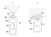
上の各実施形態では、電磁波として電波を用いることを前提として説明を行った。これに対し、第15の実施形態の物体検知システム1Qでは、電磁波として、可視光線、赤外線、または紫外線などの光線を用いる。
The above embodiments have been described on the assumption that radio waves are used as electromagnetic waves. On the other hand, in the
すなわち、図30に、上に述べた第2の実施形態の物体検知システム1Bと同じシステム構成の物体検知システム1Qが示されている。
That is, FIG. 30 shows an
図30において、物体検知システム1Qは、無線送受信集合装置3Q、無線検知装置7Q、およびサーバ8を備える。無線送受信集合装置3Qは、支持部材11Qおよび光信号送受信器13a〜dを備える。つまり、ここでは、無線送受信手段として、光信号送受信器13a〜dが用いられる。
In FIG. 30, the
支持部材11Qは、4つの光信号送受信器13a〜dを支持する機能を有する。つまり、支持部材11Qは、平面視が正方形の直方体状または正四角注状に形成されている。周囲の4つの面HM1〜4のそれぞれほぼ中央部に、光信号送受信器13a〜dが1つずつ配置される。
The
なお、支持部材11Qの材料として、ここでは光を透過させない不透明部材である遮蔽部材が用いられる。しかし、光信号送受信器13a〜dが必要な指向性を有する限りにおいて、支持部材11Qそれ自体に遮蔽部材を用いなくてもよい。光信号送受信器13a〜dには、指向性の方向以外に光を発射しないように遮蔽部材が用いられるが、光信号送受信器13a〜dが支持部材11Qに取り付けられたときに、光信号送受信器13a〜dのその遮蔽部材が支持部材11Qの一部であるとして扱えばよい。
Here, a shielding member that is an opaque member that does not transmit light is used as the material of the
光信号送受信器13a〜dは、フォトダイオードなどの受光素子、発光ダイオードまたはレーザダイオードなどの発光素子、レンズまたは偏向部材などの光学部材、および、それらを駆動し必要な信号処理を行う動作回路本体部分などが、遮蔽部材を用いて形成された適当なハウジングに納められ、1つのデバイスまたは部品として構成されたものである。
The
光信号送受信器13の構成の一例が図31(b)に示されている。
An example of the configuration of the
図31(b)において、光信号送受信器13は、遮蔽部材などを用いて形成されたハウジング130に、送受信部131、制御処理部132、メモリ133、および光信号接面展開部材135などが設けられる。
In FIG. 31B, the optical signal transmitter /
送受信部131は、フォトダイオードなどの受光素子、発光ダイオードまたはレーザダイオードなどの発光素子、レンズまたは偏向部材などの光学部材などからなり、光信号の送信および受信を行う。
The transmission /
制御処理部132は、必要な信号処理を行い、光信号送受信器13の全体を制御する。制御処理部132に、電波によってサーバ8などと通信を行って情報の送受信を行うことのできるインタフェースを設けてもよい。
The
メモリ133は、当該光信号送受信器13の識別情報DS、その他の種々の情報などを記憶する。
The
光信号接面展開部材135は、遮蔽部材、レンズ、反射部材、偏向部材などの光学部材が適当に組み合わされたものである。光信号接面展開部材135によって、送受信部131による送受信の指向性の範囲が、前方180度の範囲となるように拡大される。
The optical signal contact
このように、光信号送受信器13a〜dは、遮蔽部材、レンズ、反射部材などが適当に組み合わされ、その前方180度の範囲において無線検知装置7Qとの間の送受信が可能となるように構成されている。
As described above, the optical signal transmitters /
無線送受信集合装置3Qにおいては、光信号送受信器13に指向性を与えるのは、光信号送受信器13に用いられたハウジング130および光信号接面展開部材135などである。この場合に、ハウジング130は遮蔽部材として機能する。しかし、光信号送受信器13それ自体によって指向性を得るのではなく、それらと支持部材11に組み込まれた遮蔽部材とを組み合わせることによって指向性を得るようにしてもよい。
In the wireless transmission /
無線検知装置7Qは、光信号送受信器13との間でデータの送受信が可能であり、無線送受信集合装置3Qおよび光信号送受信器13に対して相対的に移動可能である。
The
図31(a)において、無線検知装置7Qは、合成樹脂などからなるケーシング70Qに、送受信部71Q、制御処理部72Q、メモリ73Q、表示部74Qなどが設けられて構成される。
In FIG. 31A, the
送受信部71Qは、フォトダイオードなどの受光素子、発光ダイオードまたはレーザダイオードなどの発光素子、レンズまたは偏向部材などの光学部材などを備え、光信号送受信器13との間で光信号による送受信を行う。送受信部71Qは、その前方の空間における所定の検知角αの範囲(検知用光範囲)DKにおいて光信号を発射し、その範囲DKにおいて光信号送受信器13との間の送受信が可能である。
The transmission /
無線送受信集合装置3Qは、支持部材11Q各面HM1〜4が、つまり光信号送受信器13a〜dの各指向性の正面が、それぞれ、西、南、東、北を向くように配置される。
The radio transmission /
各面HM1〜4への接面または指向性の限界面が、境界面KK1〜4である。各境界面KK1〜4の前方が、各光信号送受信器13a〜dについて指向性を持った検知可能領域EK1〜4である。
The contact surfaces or directivity limit surfaces to the surfaces HM1 to HM4 are boundary surfaces KK1 to KK4. The front sides of the boundary surfaces KK1 to KK4 are detectable areas EK1 to EK4 having directivity with respect to the
したがって、例えば、無線検知装置7Qが図30に示す位置にあるときに、その位置は検知可能領域EK1でもありかつ検知可能領域EK2でもある。この場合に、無線検知装置7Qは、2つの光信号送受信器13a、13bと同時に送受信を行うことが可能である。
Therefore, for example, when the
この場合に、2つの光信号送受信器13a、13bと実際に送受信を行ったとすると、無線検知装置7Qは、2つの検知可能領域EK1、2の重なる領域、つまり識別可能領域ES1に存在したこととなり、これが無線検知装置7Qの物体存在領域EEとして検知される。
In this case, if transmission / reception is actually performed with the two optical signal transmitters /
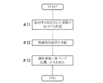
次に、上に述べた物体検知システム1,1B〜Qにおける検知の概略の手順をフローチャートに基づいて説明する。
Next, an outline procedure of detection in the
図32において、複数のRFタグ12などを適当な支持部材11などに配置し、それらの指向性を限定する(#11)。その場合に、支持部材11それ自体、または支持部材11の表面などに適用された遮蔽部材によって、RFタグ12などの指向性を限定する。または、支持部材11とは別の遮蔽部材を用い、RFタグ12などをその遮蔽部材の表面に配置しまたは埋め込むことによって、指向性を限定するようにしてもよい。このようにして、例えば無線送受信集合装置3などを形成する。必要な情報を、RFタグ12、無線検知装置7、サーバ8などに記録しまたは登録する。
In FIG. 32, a plurality of RF tags 12 and the like are arranged on an
無線検知装置7などを物体BTとともに移動させる(#12)。このとき、無線検知装置7などを必要に応じて回転し、適当な方向に向くようにする。
The
無線検知装置7がRFタグ12などを検知し、識別情報DSを得ると、得られた識別情報DSに基づいて、または得られなかった識別情報DSに基づいて、無線検知装置7の位置、方向などを判断する(#13)。無線検知装置7の位置、方向などを判断するに際して、RFタグ12などの指向性によって識別される複数の識別可能領域ESのうちのいずれの領域に存在するかを検知する。
When the
なお、必要に応じて、無線検知装置7などに複数のRFタグ12などの識別情報DSを予め記憶させておけばよい。
Note that identification information DS such as a plurality of RF tags 12 may be stored in advance in the
以上、種々の実施形態において述べたように、無線送受信集合装置3A〜Qおよび無線検知装置7,7Qを使用目的に合わせて製作し、必要な箇所に必要な個数の無線送受信集合装置3を設置し、互いに独立した必要な個数の無線検知装置7,7Qを用いることにより、各無線検知装置7,7Qと一体に移動する物体BTの方向、距離、位置などをリアルタイムで検知することができる。この場合に、無線送受信集合装置3A〜Qを設置する箇所は固定されている必要はなく、動いていてもよい。
As described above in the various embodiments, the wireless transmission / reception aggregation devices 3A to 3Q and the
上に述べた各実施形態において、タグ登録データTTG1として、探索物品情報を集合装置情報JSに含ませて記録しておいてもよいことを述べた。これによって、RFタグ12または光信号送受信器13を検知することにより、探索物品情報に基づいて、物品などの探索を行うことができる。
In each of the embodiments described above, it has been described that the search article information may be included in the aggregation device information JS and recorded as the tag registration data TTG1. Accordingly, by detecting the
すなわち、無線検知装置7,7Qが検知したRFタグ12または光信号送受信器13から送られた識別情報DSに基づいて、それに対応した探索物品情報を得ることにより、無線検知装置7,7Qを操作するユーザは探索しようとする物品の位置、方向などを知ることができる。
That is, based on the identification information DS sent from the
探索物品情報として、例えば、無線送受信集合装置3と関連付けられている機器、装置、設備、備品、道具、物品、商品、書籍、書類、美術品、貴重品、医薬品、食品、材料品、梱包物、ビン、缶、ペットボトル、トレイ、構築物、建物、柱、壁面、天井面、床面、建具、什器、工場、プラント、配管、配線、港湾、農場、ビニールハウス、温室、駅構内、空港内、乗降場、駐車場、駐輪場、乗り物、街路、歩道、出入り口、通過ゲート、窓、通路、図書館、美術館、博物館、映画館、劇場、百貨店、地下街、スーパーマーケット、コンビニ、ドラッグストア、家電量販店、パソコンショップ、カー用品店、ショッピングモール、ホームセンター、レンタルショップ、介護ベッド、介護用品、衣料、装身具、収納棚、パレット、掲示物、案内物、観光地、神社仏閣、レジャー施設、遊園地、遊技場、ゲーム機、人物、動物、ペット、植物、鉱物、またはそれらの個別構成部品などについての情報とすることができる。これによって、それらの探索や追跡が可能となる。 As search article information, for example, equipment, devices, equipment, fixtures, tools, articles, merchandise, books, documents, artworks, valuables, pharmaceuticals, foods, materials, and packages associated with the wireless transmission / reception aggregation device 3 , Bottles, cans, plastic bottles, trays, structures, buildings, pillars, walls, ceilings, floors, joinery, fixtures, factories, plants, piping, wiring, harbors, farms, plastic houses, greenhouses, stations, airports , Platform, parking lot, bicycle parking lot, vehicle, street, sidewalk, doorway, passing gate, window, passage, library, museum, museum, movie theater, theater, department store, underground mall, supermarket, convenience store, drug store, home appliance mass retailer, Computer shop, car supply store, shopping mall, home center, rental shop, nursing bed, nursing supplies, clothing, accessories, storage shelf, pallet, bulletin, guidance , It is possible to tourist sites, shrines and temples, leisure facilities, amusement parks, amusement park, a game machine, a person, animal, pets, plants, and information about, such as mineral or their individual components, to. This makes it possible to search and track them.
また、無線送受信集合装置3A〜Qが固定されていて、その固定箇所の位置が別の手段で特定されている場合には、無線送受信集合装置3からの位置関係、例えば方向と距離によって、無線検知装置7,7Qの現在位置の把握が容易に実現できる。これにより、当該無線検知装置7,7Qに関連付けられている機器、装置、備品、道具、物品、商品、乗り物、車椅子、介護用品、装身具、ゲーム機、人物、動物、ペット、装備などについて、その所在位置を容易に確認することが可能である。
In addition, when the wireless transmission / reception aggregation devices 3A to Q are fixed and the position of the fixed part is specified by another means, the wireless transmission / reception aggregation device 3 wirelessly depends on the positional relationship from the wireless transmission / reception aggregation device 3, for example, the direction and the distance. The current position of the
上に述べた各実施形態において、RFタグ12および光信号送受信器13は、自らの識別情報DSを無線検知装置7,7Qに送信し、無線検知装置7,7Qにおいて、受信した識別情報DSに基づいて種々の処理を行い、領域、位置、方向、距離などを検知した。
In each of the embodiments described above, the
しかし、そのような識別情報DSとして、RFタグ12または光信号送受信器13それ自体における位置情報、指向性に関する情報、境界面(境界線)KKに関する情報、検知可能領域EKに関する情報などを記憶しておいて送信し、それらの情報を無線検知装置7,7Qが受信するようにしてもよい。このようにした場合には、無線検知装置7,7Qまたはサーバ8において、RFタグ12または光信号送受信器13と識別情報DSとの対応関係を予め記録しておく必要がなくなる。
However, as such identification information DS, position information in the
なお、その場合に、無線検知装置7,7Qにおいて、またはサーバ8において、それらの情報に基づいて物体存在領域EE、方向、距離などを検知すればよい。
In this case, the
上に述べた各実施形態において、無線送受信手段として、RFタグ12、アンテナATとRFID集中機構12PS、または光信号送受信器13を用いた。しかし、これら以外に、使用目的などに応じて、種々の構成の無線送受信手段を用いることができる。例えば、使用する周波数または波長、空中線電力または出力電力、指向性、送受信する情報の内容、送受信の手順などを、使用目的または規模などに応じて選定すればよい。また、無線送受信手段の形態を、1つの集積回路チップ、複数の集積回路チップを搭載したプリント回路基板、または複数のプリント回路基板をハウジング内に実装したデバイスなど、種々の形態の無線機器とすることが可能である。
In each of the embodiments described above, the
上に述べた各実施形態において、無線送受信集合装置3A〜Qは、使用目的などに応じて種々のサイズとすることができる。例えば、直径または一辺の長さが数センチメートル〜十センチメートル程度の小型のもの、十センチメートル程度〜数十センチメートル程度の中型のもの、数十センチメートル程度〜1メートル程度の大型のもの、1メートル程度以上の超大型のものなど、使用目的や規模などに応じてサイズを選定すればよい。その場合に、取り付ける無線送受信手段の仕様および個数なども、適当なものを選定すればよい。 In each of the embodiments described above, the radio transmission / reception aggregation devices 3A to 3Q can have various sizes according to the purpose of use. For example, a small one having a diameter or a side length of several centimeters to tens of centimeters, a medium sized one having about tens of centimeters to several tens of centimeters, or a large one having about tens of centimeters to about one meter What is necessary is just to select size according to a use purpose, a scale, etc., such as a super large thing about 1 meter or more. In that case, it is only necessary to select an appropriate specification and number of wireless transmission / reception means to be attached.
また、無線送受信手段それ自体に指向性を持たせた場合に、指向性を生じさせるために無線送受信手段に用いられている遮蔽部材は、支持部材11,11A〜Qの一部であるとして扱えばよい。
Further, when the directivity is given to the wireless transmission / reception means itself, the shielding member used in the wireless transmission / reception means for generating directivity can be handled as being a part of the
上に述べた各実施形態において述べた事項は、矛盾がない限り当該実施形態以外の実施形態についても適用することができる。また、各実施形態において述べた事項を必要に応じて互いに組み合わせることも可能である。 The matters described in each embodiment described above can be applied to other embodiments as long as there is no contradiction. In addition, the matters described in the embodiments can be combined with each other as necessary.
上に述べた各実施形態において、支持部材11A〜Q、RFタグ12、光信号送受信器13、無線送受信集合装置3A〜Q、無線検知装置7,7Q、物体検知システム1,1B〜Qの各部または全体の構成、構造、形状、寸法、個数、配置、材料、形成方法、形成順序、判断方法、処理方法、演算方法などは、本発明の主旨に沿って適宜変更することができる。
In each of the above-described embodiments, the support members 11A to Q, the
1,1B〜Q 物体検知システム
3,3A〜Q 無線送受信集合装置
7,7Q 無線検知装置
11,11A〜Q 支持部材
12 RFタグ(無線送受信手段)
13 光信号送受信器(無線送受信手段)
AT アンテナ(無線送受信手段)
KK 境界面(境界線)
EK 検知可能領域
DS 識別情報
ES 識別可能領域
EE 物体存在領域
1, 1B-Q Object detection system 3, 3A-Q Wireless transmission /
13 Optical signal transceiver (wireless transceiver)
AT antenna (radio transmission / reception means)
KK boundary surface (boundary line)
EK Detectable area DS Identification information ES Identifiable area EE Object existence area
Claims (15)
電磁波の送受信が可能であり自らの識別情報を送信することが可能な無線送受信手段を、当該無線送受信手段よりも大きく電磁波を透過させない遮蔽部材の表面または周囲に配置しまたは埋め込むことによって当該無線送受信手段による送受信の指向性を限定しておき、
前記遮蔽部材によって指向性が限定された前記無線送受信手段を、互いの指向性が異なるように複数配置し、
前記無線送受信手段との間で前記無線送受信手段に対して空間的拡がりを持って送受信が可能な無線検知装置を前記物体とともに前記複数の無線送受信手段に対して相対的に移動させ、
前記無線検知装置によって受信された無線送受信手段の前記識別情報に基づいて、前記複数の無線送受信手段の指向性によって識別される複数の領域のうちのいずれの領域に前記物体が存在するかを検知するものであり、
前記遮蔽部材を用いて支持部材が形成されており、
前記複数の無線送受信手段は、前記支持部材の表面または周囲に配置されまたは埋め込まれ、
前記支持部材と前記複数の無線送受信手段とによって無線送受信集合装置が形成され、 前記複数の無線送受信手段は、前記支持部材の表面に設けられた多数の凹部のそれぞれにおいて、電磁波を透過させる非遮蔽部材を介して支持されるように配置されまたは埋め込まれている、
ことを特徴とする物体の存在領域の検知方法。 A method for detecting a region where an object exists,
Radio transmission / reception means capable of transmitting / receiving electromagnetic waves and capable of transmitting identification information of itself is arranged or embedded on the surface of or around a shielding member that is larger than the radio transmission / reception means and does not transmit electromagnetic waves. Limit the directivity of transmission and reception by means,
A plurality of the wireless transmission / reception means whose directivities are limited by the shielding member are arranged so that the directivity is different from each other,
A wireless detection device capable of transmitting and receiving with the wireless transmission / reception means with a spatial expansion relative to the wireless transmission / reception means is moved relative to the plurality of wireless transmission / reception means together with the object,
Based on the identification information of the wireless transmission / reception means received by the wireless detection device, it is detected in which of the plurality of areas identified by the directivity of the plurality of wireless transmission / reception means. Is what
A support member is formed using the shielding member,
The plurality of wireless transmission / reception means are arranged or embedded on the surface or the periphery of the support member,
The support member and the plurality of wireless transmission / reception means form a wireless transmission / reception aggregation device, and the plurality of wireless transmission / reception means are non-shielding that transmits electromagnetic waves in each of a plurality of recesses provided on the surface of the support member. Arranged or embedded to be supported via a member,
A method for detecting a region where an object exists.
前記無線検知装置によって受信されたまたは受信されなかった無線送受信手段の前記識別情報に基づいて、前記複数の領域のうちのいずれの領域に前記物体が存在するかを検知する、
請求項1記載の物体の存在領域の検知方法。 In the wireless detection device, the identification information of the plurality of wireless transmission / reception means is stored in advance,
Based on the identification information of the wireless transmission / reception means received or not received by the wireless detection device, it is detected in which of the plurality of regions the object is present,
The detection method of the presence area | region of the object of Claim 1.
前記複数の無線送受信手段は、前記多角柱の各側面にまたは前記円柱の側面であって仮想円周に沿って配置されまたは埋め込まれており、
前記無線送受信手段の前記識別情報に基づいて、2次元的に識別される領域のうちのいずれの領域に前記物体が存在するかを検知する、
請求項1または2記載の物体の存在領域の検知方法。 The support member has a polygonal or cylindrical shape,
The plurality of wireless transmission / reception means are arranged or embedded on each side surface of the polygonal column or a side surface of the cylinder and along a virtual circumference,
Based on the identification information of the wireless transmission / reception means, detecting in which of the two-dimensionally identified areas the object is present;
The method for detecting an existence area of an object according to claim 1 or 2 .
前記複数の無線送受信手段は、前記正多面体または球の表面に配置されまたは埋め込まれており、
前記無線送受信手段の前記識別情報に基づいて、3次元的に識別される領域のうちのいずれの領域に前記物体が存在するかを検知する、
請求項1または2記載の物体の存在領域の検知方法。 The support member has a regular polyhedron or sphere shape,
The plurality of wireless transmission / reception means are arranged or embedded on the surface of the regular polyhedron or sphere,
Based on the identification information of the wireless transmission / reception means, detecting in which area of the three-dimensionally identified area the object is present;
The method for detecting an existence area of an object according to claim 1 or 2 .
前記複数の無線送受信手段は、前記回転楕円体の表面に配置されまたは埋め込まれており、
前記無線送受信手段の前記識別情報に基づいて、3次元的に識別される領域のうちのいずれの領域に前記物体が存在するかを検知する、
請求項1または2記載の物体の存在領域の検知方法。 The support member has a spheroid shape,
The plurality of wireless transmission / reception means are arranged or embedded in the surface of the spheroid,
Based on the identification information of the wireless transmission / reception means, detecting in which area of the three-dimensionally identified area the object is present;
The method for detecting an existence area of an object according to claim 1 or 2 .
前記複数の無線送受信手段は、前記回転楕円体の表面であって前記回転楕円体の回転軸上の異なる点を中心とした半径の異なる複数の仮想円周上にそれぞれ配置されまたは埋め込まれており、
前記無線検知装置によって受信された無線送受信手段についての指向性の境界線に基づいて、前記無線検知装置と前記無線送受信集合装置との間の距離情報を取得する、
請求項1または2記載の物体の存在領域の検知方法。 The support member has a spheroid shape,
The plurality of wireless transmission / reception means are respectively arranged or embedded on a plurality of virtual circumferences having different radii around a different point on a rotation axis of the spheroid on the surface of the spheroid. ,
Obtaining distance information between the wireless detection device and the wireless transmission and reception aggregation device based on a directivity boundary line for the wireless transmission and reception means received by the wireless detection device;
The method for detecting an existence area of an object according to claim 1 or 2 .
請求項1ないし6のいずれかに記載の物体の存在領域の検知方法。 The wireless transmission / reception means is RFID,
The method for detecting an existence area of an object according to any one of claims 1 to 6 .
前記支持部材には、前記各アンテナによって送受信される電磁波を生成しまたは処理する信号処理装置が設けられている、
請求項1ないし6のいずれかに記載の物体の存在領域の検知方法。 The wireless transmission / reception means is an antenna,
The support member is provided with a signal processing device that generates or processes electromagnetic waves transmitted and received by the antennas.
The method for detecting an existence area of an object according to any one of claims 1 to 6 .
前記無線送受信手段には、発光手段および受光手段が備えられ、
前記無線検知装置には、光信号送受信手段が備えられている、
請求項1ないし6のいずれかに記載の物体の存在領域の検知方法。 Light is used as the electromagnetic wave,
The wireless transmission / reception means includes a light emitting means and a light receiving means,
The wireless detection device is provided with optical signal transmission / reception means,
The method for detecting an existence area of an object according to any one of claims 1 to 6 .
前記無線検知装置を2次元的な面内において回転させ、前記各無線送受信集合装置に配置された前記複数の無線送受信手段の前記識別情報に基づいて、2次元的な面内における前記物体の位置を検知する、
請求項1ないし6のいずれかに記載の物体の存在領域の検知方法。 A plurality of the wireless transmission and reception aggregation devices are two-dimensionally arranged;
The position of the object in a two-dimensional plane based on the identification information of the plurality of radio transmission / reception means arranged in the respective radio transmission / reception aggregation devices by rotating the radio detection device in a two-dimensional plane Detect,
The method for detecting an existence area of an object according to any one of claims 1 to 6 .
前記無線検知装置を3次元的な空間内において回転させ、前記各無線送受信集合装置に配置された前記複数の無線送受信手段の前記識別情報に基づいて、3次元的な面内における前記物体の位置を検知する、
請求項1ないし6のいずれかに記載の物体の存在領域の検知方法。 A plurality of the wireless transmission and reception aggregation devices are arranged three-dimensionally;
The position of the object in a three-dimensional plane based on the identification information of the plurality of wireless transmission / reception means arranged in each wireless transmission / reception aggregation device by rotating the wireless detection device in a three-dimensional space Detect,
The method for detecting an existence area of an object according to any one of claims 1 to 6 .
電磁波を透過させない遮蔽部材を用いて形成された支持部材と、
当該支持部材よりも小さく電磁波の送受信が可能でありかつ自らの識別情報を送信することが可能であって、前記支持部材の表面または周囲に配置されまたは埋め込まれることによって、それぞれ送受信の指向性が限定された、複数の無線送受信手段と、
前記無線送受信手段との間で送受信が可能であり、前記物体とともに前記複数の無線送受信手段に対して相対的に移動可能な無線検知装置と、
前記無線検知装置によって受信された無線送受信手段の前記識別情報に基づいて、前記複数の無線送受信手段の指向性によって識別される複数の領域のうちのいずれの領域に前記物体が存在するかを検知する検知処理手段と、を有し、
前記複数の無線送受信手段は、前記支持部材の表面に設けられた多数の凹部のそれぞれにおいて、電磁波を透過させる非遮蔽部材を介して支持されるように配置されまたは埋め込まれている、
ことを特徴とする物体検知システム。 An object detection system for detecting a region where an object exists,
A support member formed using a shielding member that does not transmit electromagnetic waves;
It is possible to transmit and receive electromagnetic waves smaller than the supporting member and transmit its own identification information, and is arranged or embedded on the surface or the periphery of the supporting member, so that directivity of transmitting and receiving is respectively provided. A plurality of limited wireless transmission and reception means;
A wireless detection device capable of transmitting / receiving to / from the wireless transmission / reception means and movable relative to the plurality of wireless transmission / reception means together with the object;
Based on the identification information of the wireless transmission / reception means received by the wireless detection device, it is detected in which of the plurality of areas identified by the directivity of the plurality of wireless transmission / reception means. and detection processing means for, the possess,
The plurality of wireless transmission / reception means are arranged or embedded so as to be supported via a non-shielding member that transmits electromagnetic waves in each of a plurality of recesses provided on the surface of the support member.
An object detection system characterized by that.
前記検知処理手段は、前記無線検知装置によって受信されたまたは受信されなかった無線送受信手段の前記識別情報に基づいて、前記複数の領域のうちのいずれの領域に前記物体が存在するかを検知する、
請求項12記載の物体検知システム。 The wireless detection device is provided with an identification information storage unit that stores in advance the identification information of the plurality of wireless transmission / reception means,
The detection processing means detects in which area of the plurality of areas the object is present based on the identification information of the wireless transmission / reception means received or not received by the wireless detection device. ,
The object detection system according to claim 12 .
複数の前記無線送受信集合装置が3次元的に配置されており、
前記無線検知装置を3次元的な空間内において回転させ、前記各無線送受信集合装置に配置された前記複数の無線送受信手段の前記識別情報に基づいて、3次元的な面内における前記物体の位置を検知する、
請求項12または13記載の物体検知システム。 A wireless transmission / reception set device is formed by the support member and the plurality of wireless transmission / reception means,
A plurality of the wireless transmission and reception aggregation devices are arranged three-dimensionally;
The position of the object in a three-dimensional plane based on the identification information of the plurality of wireless transmission / reception means arranged in each wireless transmission / reception aggregation device by rotating the wireless detection device in a three-dimensional space Detect,
The object detection system according to claim 12 or 13 .
電磁波を透過させない遮蔽部材を用いて形成された支持部材と、
当該支持部材よりも小さく無線検知装置との間で電磁波の送受信が可能でありかつ自らの識別情報を前記無線検知装置に送信することが可能であって、前記支持部材の表面または周囲に配置されまたは埋め込まれることによって、それぞれ送受信の指向性が限定された、複数の無線送受信手段と、を有し、
前記複数の無線送受信手段は、前記支持部材の表面に設けられた多数の凹部のそれぞれにおいて、電磁波を透過させる非遮蔽部材を介して支持されるように配置されまたは埋め込まれている、
ことを特徴とする無線送受信集合装置。 A wireless transmission and reception aggregation device used to detect an area where an object exists,
A support member formed using a shielding member that does not transmit electromagnetic waves;
It is smaller than the support member, can transmit and receive electromagnetic waves to and from the wireless detection device, and can transmit its own identification information to the wireless detection device, and is disposed on or around the support member. or by being embedded, possess directivity of transmission and reception is limited, respectively, and a plurality of radio transceiver means, a
The plurality of wireless transmission / reception means are arranged or embedded so as to be supported via a non-shielding member that transmits electromagnetic waves in each of a plurality of recesses provided on the surface of the support member.
A wireless transmission / reception aggregation device.
Priority Applications (1)
| Application Number | Priority Date | Filing Date | Title |
|---|---|---|---|
| JP2010097816A JP5531205B2 (en) | 2010-04-21 | 2010-04-21 | Object detection method, object detection system, and wireless transmission / reception aggregation device |
Applications Claiming Priority (1)
| Application Number | Priority Date | Filing Date | Title |
|---|---|---|---|
| JP2010097816A JP5531205B2 (en) | 2010-04-21 | 2010-04-21 | Object detection method, object detection system, and wireless transmission / reception aggregation device |
Publications (2)
| Publication Number | Publication Date |
|---|---|
| JP2011227755A JP2011227755A (en) | 2011-11-10 |
| JP5531205B2 true JP5531205B2 (en) | 2014-06-25 |
Family
ID=45043014
Family Applications (1)
| Application Number | Title | Priority Date | Filing Date |
|---|---|---|---|
| JP2010097816A Active JP5531205B2 (en) | 2010-04-21 | 2010-04-21 | Object detection method, object detection system, and wireless transmission / reception aggregation device |
Country Status (1)
| Country | Link |
|---|---|
| JP (1) | JP5531205B2 (en) |
Families Citing this family (4)
| Publication number | Priority date | Publication date | Assignee | Title |
|---|---|---|---|---|
| WO2015101676A1 (en) | 2014-01-06 | 2015-07-09 | Uresh Ag | Aseptic pipeline pig with identification means |
| JP2017191592A (en) * | 2016-04-06 | 2017-10-19 | 東芝テック株式会社 | Wireless tag device, wireless tag communication device, and wireless tag communication system |
| CN107273964A (en) * | 2016-04-06 | 2017-10-20 | 东芝泰格有限公司 | Wireless tag device, wireless tag communication device, and wireless tag communication system |
| JP2021195161A (en) * | 2020-06-16 | 2021-12-27 | パナソニックIpマネジメント株式会社 | Beverage supply device |
Family Cites Families (4)
| Publication number | Priority date | Publication date | Assignee | Title |
|---|---|---|---|---|
| JP2006153828A (en) * | 2004-11-30 | 2006-06-15 | Zeo System:Kk | Infrared id tag position retrieving apparatus |
| JPWO2006129370A1 (en) * | 2005-06-03 | 2008-12-25 | 株式会社日立超エル・エス・アイ・システムズ | RFID tag structure and RFID evaluation apparatus |
| JP2007108144A (en) * | 2005-10-17 | 2007-04-26 | Toshiba Tec Corp | Mobile object management system and mobile device |
| JP2009117507A (en) * | 2007-11-05 | 2009-05-28 | Seiko Epson Corp | Semiconductor device |
-
2010
- 2010-04-21 JP JP2010097816A patent/JP5531205B2/en active Active
Also Published As
| Publication number | Publication date |
|---|---|
| JP2011227755A (en) | 2011-11-10 |
Similar Documents
| Publication | Publication Date | Title |
|---|---|---|
| US20200364381A1 (en) | Cold storage environmental control and product tracking | |
| CN102576063B (en) | Rfid location system | |
| US11046562B2 (en) | Shopping facility assistance systems, devices and methods | |
| US20210248283A1 (en) | Methods and apparatus for persistent location based digital content | |
| US20180346299A1 (en) | Apparatus and method of obtaining location information of a motorized transport unit | |
| US12086508B2 (en) | Method and apparatus for location determination of wearable smart devices | |
| ES2388854T3 (en) | Identification and tracking of articles using electronic shadows created by RFID tags | |
| JP5531205B2 (en) | Object detection method, object detection system, and wireless transmission / reception aggregation device | |
| CN107851241A (en) | System and method for the positioning object in facility | |
| GB2572084A (en) | Shopping facility assistance systems, devices and methods | |
| JP2009023740A (en) | Information collection system and information collection robot | |
| US9741225B1 (en) | Safety detection system and method | |
| CN103068043A (en) | Indoor accurately positioning method based on wireless fidelity (WIFI) and acceleration sensor | |
| US20210142632A1 (en) | Systems and methods for spatial sensing and tracking of objects in a space | |
| US10347026B2 (en) | Information processing apparatus with location based display | |
| US10378898B2 (en) | Methods and systems for use in indicating directions for direction finding systems | |
| CN206322203U (en) | A kind of alignment system based on RFID double frequency technologies | |
| CN102226910B (en) | Regional logistics moving monitoring positioning method | |
| EP2664942B1 (en) | Methods and systems for use in selecting targets for direction finding systems | |
| CN106716053A (en) | Apparatus for recognizing three-dimensional pose and location of moving object | |
| US20170094460A1 (en) | Mobile Communications Devices | |
| CN114040322A (en) | Space positioning method and device, computer equipment and storage medium | |
| US11900021B2 (en) | Provision of digital content via a wearable eye covering | |
| JP2022030366A (en) | Information processor, program, and information processing method | |
| Catarinucci et al. | Enhancing Worker Safety in Unmanned Agricultural Environments through the Integration of RFID, RTK, UWB, and LIDAR: Insights from Research Projects |
Legal Events
| Date | Code | Title | Description |
|---|---|---|---|
| A521 | Request for written amendment filed |
Free format text: JAPANESE INTERMEDIATE CODE: A821 Effective date: 20130402 |
|
| A711 | Notification of change in applicant |
Free format text: JAPANESE INTERMEDIATE CODE: A711 Effective date: 20130402 |
|
| A621 | Written request for application examination |
Free format text: JAPANESE INTERMEDIATE CODE: A621 Effective date: 20130418 |
|
| A521 | Request for written amendment filed |
Free format text: JAPANESE INTERMEDIATE CODE: A821 Effective date: 20130404 |
|
| A521 | Request for written amendment filed |
Free format text: JAPANESE INTERMEDIATE CODE: A821 Effective date: 20130422 |
|
| A977 | Report on retrieval |
Free format text: JAPANESE INTERMEDIATE CODE: A971007 Effective date: 20131029 |
|
| A131 | Notification of reasons for refusal |
Free format text: JAPANESE INTERMEDIATE CODE: A131 Effective date: 20131112 |
|
| A521 | Request for written amendment filed |
Free format text: JAPANESE INTERMEDIATE CODE: A523 Effective date: 20131224 |
|
| TRDD | Decision of grant or rejection written | ||
| A01 | Written decision to grant a patent or to grant a registration (utility model) |
Free format text: JAPANESE INTERMEDIATE CODE: A01 Effective date: 20140304 |
|
| A61 | First payment of annual fees (during grant procedure) |
Free format text: JAPANESE INTERMEDIATE CODE: A61 Effective date: 20140310 |
|
| R150 | Certificate of patent or registration of utility model |
Ref document number: 5531205 Country of ref document: JP Free format text: JAPANESE INTERMEDIATE CODE: R150 |
|
| R250 | Receipt of annual fees |
Free format text: JAPANESE INTERMEDIATE CODE: R250 |
|
| R250 | Receipt of annual fees |
Free format text: JAPANESE INTERMEDIATE CODE: R250 |
|
| R250 | Receipt of annual fees |
Free format text: JAPANESE INTERMEDIATE CODE: R250 |
|
| R250 | Receipt of annual fees |
Free format text: JAPANESE INTERMEDIATE CODE: R250 |
|
| R250 | Receipt of annual fees |
Free format text: JAPANESE INTERMEDIATE CODE: R250 |
|
| R250 | Receipt of annual fees |
Free format text: JAPANESE INTERMEDIATE CODE: R250 |
|
| R250 | Receipt of annual fees |
Free format text: JAPANESE INTERMEDIATE CODE: R250 |
|
| R250 | Receipt of annual fees |
Free format text: JAPANESE INTERMEDIATE CODE: R250 |