JP5530775B2 - Manufacturing method of interior bag and jig used therefor - Google Patents
Manufacturing method of interior bag and jig used therefor Download PDFInfo
- Publication number
- JP5530775B2 JP5530775B2 JP2010066963A JP2010066963A JP5530775B2 JP 5530775 B2 JP5530775 B2 JP 5530775B2 JP 2010066963 A JP2010066963 A JP 2010066963A JP 2010066963 A JP2010066963 A JP 2010066963A JP 5530775 B2 JP5530775 B2 JP 5530775B2
- Authority
- JP
- Japan
- Prior art keywords
- jig
- bag
- cylindrical body
- ring
- shape
- Prior art date
- Legal status (The legal status is an assumption and is not a legal conclusion. Google has not performed a legal analysis and makes no representation as to the accuracy of the status listed.)
- Expired - Fee Related
Links
Images


Description
この発明は、外装容器内に収納される可撓性を有する内装袋の製造方法、さらに詳しくは、筒状胴部の上端と下端を筒口付きの天板と底板で閉鎖したクローズ状の内装袋を容易に得ることができる製造方法と、その製造方法に使用する治具に関するものである。 The present invention relates to a method of manufacturing a flexible interior bag accommodated in an exterior container, and more specifically, a closed interior bag in which the upper and lower ends of a cylindrical body portion are closed with a top plate and a bottom plate with a cylinder opening. The present invention relates to a manufacturing method capable of easily obtaining the above and a jig used in the manufacturing method.
例えば、保形部材となるドラム缶等の比較的剛性のある外装容器の内側に装着し、その内部に各種液体や粉体を収納し、これらの保存や輸送を行う可撓性の内装容器として合成樹脂製の内装袋が使用されている。 For example, it is mounted inside a relatively rigid outer container such as a drum can as a shape-retaining member, and various liquids and powders are stored inside it and synthesized as a flexible inner container for storing and transporting them. Resin-made interior bags are used.
従来、上記のような内装袋の一般的な製造方法は、熱可塑性合成樹脂シートを用いた筒状胴部の下端側に同じく熱可塑性合成樹脂製シートからなる底板等を溶着することで上端開放の袋体に成形するようにしていた。 Conventionally, the general manufacturing method of the interior bag as described above is to open the upper end by welding a bottom plate or the like made of a thermoplastic synthetic resin sheet to the lower end side of the cylindrical body portion using the thermoplastic synthetic resin sheet. To be molded into a bag body.
上記袋体の製造において、筒状胴部に底板等の端部材を取り付ける際の作業を容易にするため、長手方向に移動可能な短管形の外リング片の外周に熱収縮性合成樹脂からなる筒状胴部(内装袋周壁材)を外嵌し、筒状胴部に底板を取り付けるための溶着片を形成する長さ分だけこの外リング片から突出させて加熱により筒状胴部の半径方向に収縮させると共に、外リング片の移動により外リング片の内周側に配設固定された円盤状の受盤で溶着片を水平状態に維持し、ここに底板となる端部材と溶着する方法が提案されている(例えば、特許文献1参照)。 In the manufacture of the bag body, a heat-shrinkable synthetic resin is used on the outer periphery of a short tubular outer ring piece that is movable in the longitudinal direction in order to facilitate work when attaching an end member such as a bottom plate to the cylindrical body. The cylindrical body part (inner bag surrounding wall material) is externally fitted, and is projected from the outer ring piece by a length that forms a welding piece for attaching the bottom plate to the cylindrical body part. The welding piece is kept in a horizontal state by a disk-shaped receiving plate which is contracted in the radial direction and arranged and fixed on the inner peripheral side of the outer ring piece by the movement of the outer ring piece, and welded to the end member which becomes the bottom plate here A method has been proposed (see, for example, Patent Document 1).
ところで、最近は、筒状胴部の下端に底板を溶着するのみならず、筒状胴部の上端に筒口付きの天板も溶着し、クローズ状の内装袋も使用されてきているが、上記特許文献1の方法では、筒状胴部の一方端に端材を取り付けるのみで、クローズ状の袋体を得ることはできなかった。
By the way, recently, not only the bottom plate is welded to the lower end of the cylindrical body part, but also the top plate with a tube opening is welded to the upper end of the cylindrical body part, and a closed interior bag has been used. In the method of
そこで、出願人は、先に、熱可塑性合成樹脂を用いた筒状体の下半部を内側に折り返して二重筒に形成し、この二重筒における内側筒及び外側筒の上端部をそれぞれ径方向の内側に向かう折り曲げ部とし、内側筒の折り曲げ部上に熱可塑性合成樹脂を用いた底板の周囲を重ね、外側筒の折り曲げ部上に熱可塑性合成樹脂を用いた天板の周囲を重ね、上記底板と外側筒の折り曲げ部の間に非溶着材を介在させた状態で、上記外側筒の折り曲げ部と天板及び内側筒の折り曲げ部と底板のそれぞれの重なり部分を周方向の全長にわたって同時に加熱溶着し、この溶着後に、天板に設けた筒口から上記非溶着材を抜き取る構成を採用することで、筒状胴部の上端側と下端側を閉鎖する溶着処理を同時に行うことで、クローズ状の袋体を得ることができる製造方法を提供した(特許文献2参照)。 Therefore, the applicant first formed a double cylinder by folding the lower half of the cylindrical body using the thermoplastic synthetic resin inward, and the upper end of the inner cylinder and the outer cylinder in the double cylinder, respectively. The bent part toward the inner side in the radial direction is used, and the periphery of the bottom plate using the thermoplastic synthetic resin is superimposed on the bent part of the inner cylinder, and the periphery of the top plate using the thermoplastic synthetic resin is superimposed on the bent part of the outer cylinder. In a state where a non-welding material is interposed between the bottom plate and the bent portion of the outer cylinder, the overlapping portions of the bent portion of the outer cylinder and the top plate and the bent portion of the inner cylinder and the bottom plate are extended over the entire length in the circumferential direction. By simultaneously heat-welding and adopting a configuration in which the non-welding material is removed from the tube opening provided in the top plate after this welding, by simultaneously performing a welding process for closing the upper end side and the lower end side of the cylindrical body part, A closed bag can be obtained Provided the manufacturing method (see Patent Document 2).
上記特許文献1の発明により、筒状胴部に底板を取り付ける作業は容易となったが、筒状胴部の一方の端部に底板等の端部材を溶着して一方端を閉鎖した後に、他方の端部に端部材を溶着しようとして、外リング片の外周に一方閉鎖済み筒状胴部を被せるのはそのままでは不可能であった。
According to the invention of the above-mentioned
また、特許文献2の発明では、筒状胴部の上端側と下端側を閉鎖する溶着処理を行うことで、両端部を端部材で閉鎖したクローズ状の内装袋が得られるが、溶着作業終了後に、天板に設けた筒口から非溶着材を抜き取る作業が必要であった。
Moreover, in invention of
この非溶着部材は、天板や底板とほぼ同じ大きさの可撓性のあるシート状であるが、溶着後のクローズ状態の内袋の天板に設けた筒口から取り出すのに手間がかかり、特に筒口が天板の大きさに比べて小さい場合、その取り出し作業が困難となり、場合によっては非溶着材を破ったり破損した上で取り出さなければならない場合もあった。 This non-welding member is a flexible sheet of the same size as the top plate and bottom plate, but it takes time to take out from the tube opening provided on the top plate of the inner bag in the closed state after welding, In particular, when the tube opening is smaller than the size of the top plate, it is difficult to take out the tube, and in some cases, the non-welded material must be taken out after being broken or damaged.
上記のように、特許文献2の製造方法によりクローズ状の内袋の製造が容易になったが、非溶着材の取り出し作業が手間がかかることと、非溶着材の破損した場合は非溶着材の材料コストがかかるという問題があった。
As described above, the manufacturing method of
また、最近の内装袋は、袋体の上端の周縁部全周に亘って側面に沿った下向きの折り返し状の係合片を設けて、この係合片をドラム缶等の外装容器の上部開口の周縁部外側に引っ掛けて、内装袋の外装容器内での落ち込みを防止することも行われているが、特許文献2の製造方法では、係合片を設けた内装袋を製造するのは困難であった。
Further, recent interior bags are provided with downwardly folded engagement pieces along the side surfaces over the entire periphery of the upper edge of the bag body, and this engagement piece is provided in the upper opening of an outer container such as a drum can. Although it is also possible to prevent the inner bag from falling in the outer container by hooking it to the outer periphery, it is difficult to manufacture the inner bag provided with the engagement piece in the manufacturing method of
この発明は、上記のような課題を解決し、クローズ状の合成樹脂製の内装袋を、低コスト、かつ確実に得ることのできる製造方法と、その方法に用いる専用の治具を提供することを課題とする。 This invention solves the above problems, and provides a manufacturing method capable of reliably and inexpensively obtaining a closed synthetic resin interior bag, and a dedicated jig used in the method. Is an issue.
上記のような課題を解決するため、請求項1の発明は、外装容器内に収納されて使用され、筒状胴部の上下端に筒口付き天板と底板とからなる端材を接合して閉鎖され全体が可撓性を有する内装袋の製造方法において、熱収縮性樹脂からなる筒状胴部の下端に適宜手段により端材を接合した上部開口の袋体に対し、筒状胴部の直径より若干大きめの直径のリング状とこのリングの対向2カ所で折り曲げて重ねた弓状とに変換自在となる治具を、袋体の上部開口部から所定寸法の位置で袋体の内側からリング状にして嵌め込み固定し、リング状の治具を下から保持可能な枠体に袋体を装着して、上部開口部を円形に保持した状態で筒状胴部の治具より上側の部分を加熱により開口部内側に収縮させて略水平状にして溶着片とし、更にこの上にもう片方の端材を重ねて溶着片と端材の周囲を加熱により溶着し、その後、治具をリング状から弓状に変換して、天板の筒口から弓状の治具を外側に取り出す構成を採用したものである。
In order to solve the above-described problems, the invention of
また、請求項2の発明は、上記請求項1に記載の内装袋の製造方法に使用される治具であって、筒状胴部の直径より若干大きめの直径のリング状とこのリングの対向2カ所で折り曲げて重ねた弓状とに変換自在となる構成を採用したものである。
The invention of
ここで、筒状胴部と底板及び天板からなる端材は、ポリエチレンのような加熱によって溶着可能な熱可塑性合成樹脂を用いて形成され、特に、筒状胴部はその上端及び下端に、天板や底板と溶着される溶着片を形成するために、加熱により収縮するものが好ましい。 Here, the end material consisting of the cylindrical body, the bottom plate, and the top plate is formed using a thermoplastic synthetic resin that can be welded by heating such as polyethylene, and in particular, the cylindrical body is at the upper and lower ends thereof. In order to form a welded piece to be welded to the top plate or the bottom plate, a material that shrinks by heating is preferable.
治具を構成する部材は、熱により合成樹脂等と溶着することのない非溶着性を有する比較的剛性のある材料とするが、金属製や合成樹脂製等特にその材料は限定されない。 The member constituting the jig is a relatively rigid material having non-weldability that is not welded to the synthetic resin or the like by heat, but the material is not particularly limited, such as a metal or synthetic resin.
治具は、リング状とした時に筒状胴部の直径より若干大きめの直径となっているので、筒状胴部の内側から筒状胴部を外側に押し広げた状態となり、筒状胴部の収縮力により挟まれることでこの治具は任意の位置で固定されることになり、袋体は治具より上に上端部を突出させた状態で開口状態を維持することになり、この部分にもう一方の端材を溶着可能となる。 The jig has a diameter slightly larger than the diameter of the cylindrical body when it is ring-shaped, so that the cylindrical body is pushed outward from the inside of the cylindrical body, and the cylindrical body This jig is fixed at an arbitrary position by being sandwiched by the shrinkage force of the bag, and the bag body maintains the open state with the upper end protruding above the jig, and this part The other end material can be welded to the other.
リング状の治具を下から保持可能な枠体としては、例えば、上部開口の袋体が入り込む程度の内径を有する筒状で、上端がリング状の治具を支えられるように水平面となったものが考えられるが、枠体としては特に筒状に限定されず、要するに、リング状の治具により上部開口状態を保持された袋体をリング状治具の部分を下から支えることで保持できるようなものであれば良く、その材料も、スチール等の金属製や他の材料等特に限定されない。 As a frame that can hold the ring-shaped jig from the bottom, for example, it has a cylindrical shape with an inner diameter that allows the bag of the upper opening to enter, and the upper end becomes a horizontal plane so that the ring-shaped jig can be supported Although the frame body is not particularly limited to a cylindrical shape, in short, the bag body in which the upper opening state is held by the ring-shaped jig can be held by supporting the ring-shaped jig portion from below. The material is not particularly limited, and the material is not particularly limited, such as a metal such as steel or other materials.
この発明は上記のような構成であり、筒状胴部の一方端に天板や底板等の端材を溶着した袋体(先に筒状胴部に溶着して袋体を形成しておく端材は、底板でも天板でもどちらでもかまわない。)に対して治具を所定の位置に固定することで、治具より上に溶着片形成部を形成し、上部開口状態を保持したまま枠体上に設置し、他方の端材の溶着工程を行った後、治具を弓状に変換して天板の筒口から取り出せば、筒状胴部の上下端を天板と底板で閉鎖したクローズ状の内装袋が完成することになる。 The present invention is configured as described above, and a bag body in which end materials such as a top plate and a bottom plate are welded to one end of the cylindrical body portion (a bag body is formed by first welding to the cylindrical body portion). The end material may be either a bottom plate or a top plate.) By fixing the jig to a predetermined position, a weld piece forming portion is formed above the jig and the upper opening state is maintained. After installing on the frame and welding the other end material, if the jig is converted into a bow and taken out from the top port of the top plate, the upper and lower ends of the cylindrical body are closed with the top and bottom plates The closed interior bag will be completed.
以上のように、この発明によると、筒状胴部の上下端を天板及び底板で閉鎖したクローズ状の内装袋を、所定の簡単な治具や枠体を使用することで極めて容易に低コストで製造することができる。 As described above, according to the present invention, the closed interior bag in which the upper and lower ends of the cylindrical body portion are closed with the top plate and the bottom plate can be extremely easily reduced by using a predetermined simple jig or frame. Can be manufactured at cost.
また、従来は難しかった、天板の周縁部全周に亘って側面に沿った下向きの折り返し状で外装容器の上部開口の周縁部外側に引っ掛けるための係合片を有する内装袋も製造が可能となった。 In addition, it is possible to manufacture an interior bag having an engagement piece for hooking on the outside of the peripheral edge of the upper opening of the outer container in a downward folded shape along the side surface over the entire peripheral edge of the top plate, which was difficult in the past. It became.
更に、閉鎖状に形成して完成した後の内装袋の内部から取り出す治具は、リング形状を対称位置にある対向2カ所で2つに折り曲げて重ねた弓状とすることができるので、破損なく天板に設けられた細い筒口から容易に取り出すことができ、何度でも再利用が可能となる。 Furthermore, the jig to be taken out from the interior of the interior bag after being formed in a closed shape can be formed into an arcuate shape by folding the ring shape in two at two opposite positions at symmetrical positions, and therefore it is damaged. It can be easily taken out from a thin tube port provided on the top plate and can be reused any number of times.
以下、この発明の実施の形態を図示例と共に説明する。
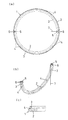
図1は、この発明の合成樹脂製の内装袋の製造方法に使用される治具1を示すもので、(a)は円形に広げた状態の平面図、(b)は弓形に折り畳んだ状態を示す斜視図、(c)は拡大断面正面図である。
Hereinafter, embodiments of the present invention will be described with reference to the drawings.
1A and 1B show a
図1(a)の円形に広げた状態の治具1は、リング状の形状で、平板をこのリング形状に切り抜いたように所定の厚みを有して剛性を確保したベース板2の上に、同じく平面をリング形状に切り抜いた前記ベース板2よりも細幅で所定の厚みを有する鏝台3が接続部材となる下駄4を複数箇所に介して接続されている。
1A is a ring-shaped
ベース板2とそれに接続される鏝台3は、共にそのリング形状の円の中心を通る直線によって分割されて対称2等分されており、ベース板2の下側の分割された部分には蝶番5が設けられており、この蝶番5の部分で分割されたベース板2を鏝台3と共に折り曲げベース板2同士を合わせるように折り畳んで図1(b)に示すような弓状とすることができる。
The
この治具1の各部寸法としては、まずリング状のベース板2及び鏝台3共にその外径は製造される内装袋の内径より若干大きめとなっており、一例として、ドラム缶用の内装袋の製造に使用するものとしては、外径がドラム缶の直径とほぼ同じ約70cm、その直径方向での幅はベース板2で約40〜45mm、鏝台3で約20〜25mm程度、厚みは両者とも4〜10mm程度としているが、製造される内装袋の種類や寸法に応じて適宜変更されるものである。
As for the dimensions of each part of the
治具1の材料は、実施形態では、一例としてベース板2はアルミ合金製で、鏝台3はステンレス製の上面にフッ素樹脂コートなどの非粘着性材料がコートされているが、これらについても、剛性を有する材料であれば実施形態のものに限定されず、金属製、樹脂製など種々の材質のものを使用できる。但し、内装袋の材料と熱により溶着することがないように、特に鏝台3の上面に関しては、四フッ化エチレン樹脂等の非溶着性を有する材料で構成するか、又は非溶着性材料を表面にコーティングしておくのが好ましい。
In the embodiment, for example, the
なお、鏝台3の分割部端部は、図1(b)の弓状の折り曲げ状態から図1(a)のドーナツ形状に戻す時に端部同士の衝突による衝撃を緩和するため、フッ素ゴムや天然ゴム等の非粘着性の緩衝材6で覆われている。また、ベース板2の蝶番付近には、紐7の一方端が接続固定されている。
It should be noted that the end of the split part of the
治具1の断面形状は、図1(c)の一部拡大断面図に示すように、ベース板2及び鏝台3共に厚み方向の上下は平面状となっており、鏝台3の上面は後述の袋体と天板の溶着時に袋体の溶着片と天板とを下から支え、ベース板2の下面は後述の枠体の上面に袋体を介して支えられることになる。またベース板2の外周部は上面と下面をなめらかな曲面で繋ぐような半円形となっており、鏝台3の断面角部は、製造する内装袋の材料である合成樹脂を攻撃しないように角がなめらかになっている。
As shown in the partially enlarged cross-sectional view of FIG. 1 (c), the
なお、ベース板2の幅が鏝台3の幅より内方に大きくなっており、これは内装袋の側面を構成する筒状胴部の上端部が加熱により内方に倒れ込んだ際、ベース板2が倒れ込んだ筒状胴部(後の天板と溶着するための溶着片)を支えて完全に下方に落ち込ませず、水平な溶着片を形成させることになる。
Note that the width of the
次に、図1で示した治具1を用いて内装袋を製造する方法を説明する。
まず、筒状に形成された合成樹脂を所定の長さに切断した筒状胴部8の下端部に、既知の方法(例えば、特許文献1の方法)にて円盤状の底板9を溶着した上端部開放の袋体10(図2参照)を用意する。
Next, a method for manufacturing an interior bag using the
First, a disk-shaped
この袋体10を構成する筒状胴部8や底板9や後述の天板等の端材としては熱可塑性合成樹脂としてポリエチレンその他の合成樹脂であって、主に透明、半透明の材質からなるが、加熱によって溶着可能な樹脂であれば材料の種類や、透明・半透明や非透明(着色等)は特に限定されない。
End members of the
なお、筒状胴部8としては、両端部に端材を溶接するための溶着片を形成するために、熱収縮性を有する樹脂を用いるのが好ましく、製法としてはインフレーション法などで上述の合成樹脂材料を筒状に形成したものを用い、更に、強度向上させる必要がある場合、二重構造やそれ以上の複合構造にする場合もある。
As the
この袋体10に対して、まず治具1を図1(b)で示した弓状に折り畳み状態にして袋体10の上端開口部11から入れて内部で蝶番5部分を広げて円形に広げ、図2に示すように、治具1を鏝台3を上側にベース板2を下側にして円形状に戻し、袋体10の上端部から所定寸法下の位置、一例として上端から7cm下の位置にて底板9や開口部11と平行状態となるように治具1を固定する。
First, the
この際、治具1の円形状とした状態での円形の外直径が、袋体10の筒状胴部8の直径より若干大きめとしてあるので、筒状胴部8を周囲外方へ押し広げ、筒状胴部8の伸縮力により治具1を内方に挟み込み、治具1は袋体10内の任意の位置で固定されることになる。
At this time, since the circular outer diameter of the
また、治具1の外周面は、図1(c)で示すように、ベース板2の外周部が上面と下面を曲面で繋ぐような半円形であり、鏝台3の外周部も角部を削った状態となっているので、治具1が筒状胴部8を押し広げて所定位置に配置する際の抵抗を少なくすることができる。
Further, as shown in FIG. 1C, the outer peripheral surface of the
次に、この上端部開放の袋体10を、図3に示すように、袋体10の底板9の直径とほぼ同じか若干大きめの寸法の内径を有する筒形状のスチール製の枠体12の内部に、底板9を下にして収納してゆく。
Next, as shown in FIG. 3, the
図4に示すように、枠体12の内径は袋体10の底板9の直径(即ち、筒状胴部8の直径)と同じか若干大きく、かつ、治具1の外径よりは小さくしてある。そのため、袋体10の底板9の部分を収縮させずにそのままの形状で収納することができ、更に、枠体12の内径が治具1の外径より小さいため、治具1の部分にて筒状胴部8を挟んで枠体12の上端部に当接してそれ以上の袋体10の枠体12内への落ち込みが阻止され、袋体10は枠体12及び治具1より上側に所定寸法(約7cm)だけ筒状胴部8の上端部を突出させた状態で固定されることになる。
As shown in FIG. 4, the inner diameter of the
次に、図4の状態で、上部から遠赤外線ヒーター等(図示せず)を近づけて輻射熱により加熱することで、熱収縮性樹脂からなる筒状胴部8の枠体12及び治具1より上に突出している部分を収縮させることで、図5に示すように、この部分が開口部11の内側に実線位置から一点鎖線位置へと倒れ込んでゆく。
Next, in the state of FIG. 4, a far-infrared heater or the like (not shown) is approached from the top and heated by radiant heat, so that the
筒状胴部8の上端が開口部11の内側方向に均等に収縮することで内側に倒れ込み、鏝台3やベース板2に支えられて水平状態になると、その後に天板と溶着により接合される溶着片13となる。
When the upper end of the
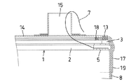
筒状胴部8の上端を加熱により水平状体の溶着片13とした後、図6に示すように、枠体12内に収納されたままの袋体10に対して円盤状の天板14を被せる。
After the upper end of the
更に、天板14に設けられている上側に突出する筒状で、内側が上下貫通する筒口15の下側から治具1の紐7を上に向けて通しておくが、こうすることによって、後にクローズ状に完成した内装袋から治具1を取り出しやすくなる。
Furthermore, the
この状態で、溶着機(図示せず)を下降させ、上記した溶着片13と天板14の周辺部との重なり部分を枠体12上に載置された治具1と溶着機で上下から挟み込み、例えば、溶着機は10〜数十mm程度の溶着幅で周方向の全長にわたる環状に加熱する。
In this state, the welding machine (not shown) is lowered, and the overlapping portion between the
この際、治具1は全体又は鏝台3の上面が非溶着材料で構成されているので、袋体10を構成する合成樹脂が溶着機の熱によって溶けていても治具1と溶着することがない。
At this time, since the
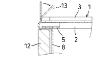
図7は枠体12内にて完成した内装袋16の正面断面図を示し、図8はその要部拡大図であり、筒状胴部8の枠体12及び治具1より上側に突出した上端部を内側へ折り曲げた溶着片13を設け、この溶着片13に筒口15を有する天板14の周囲を重ねて溶着することで、上下端を天板14及び底板9の端板で閉鎖したクローズ袋に形成されている。
FIG. 7 is a front sectional view of the
内装袋16を枠体12から上方向へ取り出した後、内装袋16の内部で筒状胴部8と天板14の溶着部付近に固定されている治具1を、その蝶番5部分で折り曲げて重ね合わせ、図1(b)で示した弓状とした後、筒口15から外部に出ている紐7を引っ張ってたぐり寄せることで、図9に示すように、天板14の筒口15から弓状となった治具1を取り出し、内装袋16が完成する。
After the
上記の方法で製造された内装袋16は、各種流体や粉体の収納用として用いることができ、例えばドラム缶の内側に装着し、ドラム缶の蓋にある上部注入口と内装袋の筒口15の位置を合わせてドラム缶に蓋をして各種液体や粉体の収納に使用し、天板14に設けた筒口15を通じて流体や粉体の出し入れが可能になる。
The
図10は、天板の周縁部全周に亘って側面に沿った下向きの折り返し状で、外装容器の上部開口周縁部外側に引っ掛ける係合片を有する内装袋を製造する実施形態を示すものであり、この実施形態の袋体10を構成する筒状胴部8は、インフレーション製法により得られた筒状体を三重に重ねて三層構造の円筒状となっているが、三層構造に限定されず、一層やそれ以外の多層構造であってもよい。
FIG. 10 shows an embodiment for producing an interior bag having an engagement piece hooked on the outer periphery of the upper opening periphery of the exterior container in a downward folded shape along the side surface over the entire periphery of the periphery of the top plate. Yes, the
この筒状胴部8の上端部付近、即ち後に溶着片13を形成する部分に、筒状胴部8と同じ材質で筒状胴部8と同じ直径を有し、上下方向が筒状胴部8より短寸法な筒状体からなる短筒体17を筒状胴部8の外側から嵌める。
In the vicinity of the upper end of the
次に、図11に示すように、筒状胴部8と短筒体17の上端同士を熱溶着等により仮溶着部18を形成することで接着しておいてから、先の実施形態と同様に、治具1を筒状胴部8の所定位置に内側から嵌め込み固定するが、この際、短筒体17の上下寸法方向の途中に治具1が嵌り込んでいるようにする。
Next, as shown in FIG. 11, the upper ends of the
筒状胴部8内部に治具1を嵌め込んだ後、先の実施形態と同様に枠体12に設置し、筒状胴部8上端部付近を加熱することで、先の実施形態と同様、三重構造の筒状胴部8の治具1より突出する上端付近を収縮させて溶着片13を形成するが、短筒体17の上側も三層の筒状胴部8と同様に内側に倒れて、図12に示すように溶着片13を形成する。
After fitting the
この際、短筒体17はその上端部が筒状胴部8と前もって溶着されており、更に、三層構造の筒状胴部8のそれぞれの層も上端部が前もって仮溶着部18で一体化しているために、溶着片13を形成するために内側に倒れ込んだ際も、溶着片13は筒状胴部8の三層および短筒体17の倒れ込み先端部が揃ってずれが生じておらず、主に透明・半透明の素材からなる内装袋であっても見栄えが良くなる。
At this time, the upper end portion of the short
この後、先の実施形態と同様に、筒口15付きの天板14を溶着することで、図13に示す内装容器が得られるが、短筒体17の溶着片13とならずに残った垂直部分が、係合片19として筒状胴部8の上端の周縁部全周に亘って側面に沿った下向きの折り返し状に形成され、この係合片19の部分は内装袋をドラム缶等の外装容器内に収納する際、外装容器の上部開口の縁部外側に引っ掛けることで、内装袋の外装容器内への落ち込みを防止することができる。
Thereafter, as in the previous embodiment, by welding the
以上、この発明の内装袋の製造方法の実施の形態を説明したが、内装袋の種類や寸法、材料、治具の寸法や材料等、及び、製造方法の詳細については、これらの実施形態にとらわれることなく、この発明の目的の範囲内で適宜変更して実施することができる。 As mentioned above, although embodiment of the manufacturing method of the interior bag of this invention was described, the details of the kind and size of the interior bag, the material, the size and material of the jig, and the manufacturing method are described in these embodiments. Without departing from the scope, the present invention can be implemented with appropriate modifications within the scope of the object of the present invention.
例えば、実施の形態では筒状胴部8に先に取り付ける端材としては底板9を取り付けて袋体10としていたが、先に天板14を取り付けて袋体10を構成し、その後に治具1を用いて底板9を袋体10に溶着するようにしてもよいし、また、枠体12の形状も図示の円筒形のスチール枠に限定されることなく、治具1を組み込んだ袋体10を、治具1を上端で支えて固定して、溶着片と端材との熱溶着を可能とするようなものであれば形状も限定されない。
For example, in the embodiment, the
1 治具
2 ベース板
3 鏝台
4 下駄
5 蝶番
6 緩衝材
7 紐
8 筒状胴部
9 底板
10 袋体
11 開口部
12 枠体
13 溶着片
14 天板
15 筒口
16 内装袋
17 短筒体
18 仮溶着部
19 係合片
DESCRIPTION OF
Claims (2)
熱収縮性樹脂からなる筒状胴部の下端に適宜手段により端材を接合した上部開口の袋体に対し、筒状胴部の直径より若干大きめの直径のリング状とこのリングの対向2カ所で折り曲げて重ねた弓状とに変換自在となる治具を、袋体の上部開口部から所定寸法の位置で袋体の内側からリング状にして嵌め込み固定し、リング状の治具を下から保持可能な枠体に袋体を装着して、上部開口部を円形に保持した状態で筒状胴部の治具より上側の部分を加熱により開口部内側に収縮させて略水平状にして溶着片とし、更にこの上にもう片方の端材を重ねて溶着片と端材の周囲を加熱により溶着し、その後、治具をリング状から弓状に変換して、天板の筒口から弓状の治具を外側に取り出すことを特徴とする内装袋の製造方法。 In the manufacturing method of the interior bag which is housed and used in the exterior container, and is closed by joining the end material composed of the top plate and the bottom plate with the tube mouth to the upper and lower ends of the cylindrical body, and the whole is flexible.
In contrast to the bag with an upper opening in which the end material is joined to the lower end of the cylindrical body made of heat-shrinkable resin by appropriate means, a ring shape having a slightly larger diameter than the diameter of the cylindrical body and two opposite positions of this ring A jig that can be converted into an arcuate shape that is bent and stacked at the top of the bag body is fitted in a ring shape from the inside of the bag body at a predetermined dimension from the top opening of the bag body and fixed, and the ring jig is fixed from below Attach the bag body to the holdable frame, and with the upper opening held in a circle, heat the upper part of the cylindrical body part from the jig to the inside of the opening and heat it to make it approximately horizontal Then, the other end material is stacked on top of this, and the periphery of the welded piece and the end material is welded by heating, and then the jig is changed from a ring shape to an arch shape, and then an arch shape is formed from the top opening of the top plate. A method for manufacturing an interior bag, wherein the jig is taken out to the outside.
Priority Applications (1)
| Application Number | Priority Date | Filing Date | Title |
|---|---|---|---|
| JP2010066963A JP5530775B2 (en) | 2010-03-23 | 2010-03-23 | Manufacturing method of interior bag and jig used therefor |
Applications Claiming Priority (1)
| Application Number | Priority Date | Filing Date | Title |
|---|---|---|---|
| JP2010066963A JP5530775B2 (en) | 2010-03-23 | 2010-03-23 | Manufacturing method of interior bag and jig used therefor |
Publications (2)
| Publication Number | Publication Date |
|---|---|
| JP2011194840A JP2011194840A (en) | 2011-10-06 |
| JP5530775B2 true JP5530775B2 (en) | 2014-06-25 |
Family
ID=44873615
Family Applications (1)
| Application Number | Title | Priority Date | Filing Date |
|---|---|---|---|
| JP2010066963A Expired - Fee Related JP5530775B2 (en) | 2010-03-23 | 2010-03-23 | Manufacturing method of interior bag and jig used therefor |
Country Status (1)
| Country | Link |
|---|---|
| JP (1) | JP5530775B2 (en) |
Families Citing this family (2)
| Publication number | Priority date | Publication date | Assignee | Title |
|---|---|---|---|---|
| CN104112316B (en) * | 2014-07-25 | 2016-06-08 | 上海博瑁机电科技有限公司 | A kind of commercialization and the industrial bubble bags automatic vending all-in-one combined |
| JP5846531B1 (en) * | 2014-08-01 | 2016-01-20 | トチセン化成工業株式会社 | Cylindrical container inner bag and method for manufacturing cylindrical container inner bag |
Family Cites Families (5)
| Publication number | Priority date | Publication date | Assignee | Title |
|---|---|---|---|---|
| JPS6226670Y2 (en) * | 1985-07-31 | 1987-07-08 | ||
| JP3817714B2 (en) * | 2001-09-10 | 2006-09-06 | 敏彦 松田 | Manufacturing method of inner bag for container can |
| JP2004066512A (en) * | 2002-08-02 | 2004-03-04 | Nisshin Sansho Kk | Method for shaping bag of bag-like shape into cylindrical vessel |
| JP3723540B2 (en) * | 2002-11-13 | 2005-12-07 | 日新産商株式会社 | Manufacturing method of synthetic resin bag |
| JP4252055B2 (en) * | 2005-09-12 | 2009-04-08 | 旭東フィルム工業株式会社 | Method for producing inner bag for circular container |
-
2010
- 2010-03-23 JP JP2010066963A patent/JP5530775B2/en not_active Expired - Fee Related
Also Published As
| Publication number | Publication date |
|---|---|
| JP2011194840A (en) | 2011-10-06 |
Similar Documents
| Publication | Publication Date | Title |
|---|---|---|
| WO2012017938A1 (en) | Container and production method thereof | |
| JP5049537B2 (en) | Self-supporting bag | |
| JP5530775B2 (en) | Manufacturing method of interior bag and jig used therefor | |
| JP2011001125A (en) | Pouch container, manufacturing method therefor, and shape-forming method | |
| WO2015012011A1 (en) | Pouch container and manufacturing method for same | |
| JP2003276741A (en) | Self-supportable bag and its manufacturing method | |
| WO2014054760A1 (en) | Pouch container | |
| JP7368222B2 (en) | Method and apparatus for manufacturing spouted pouch containers | |
| JP5943247B2 (en) | Cup-shaped container | |
| CA2446792C (en) | Method for making bags comprising slider-actuated closure profiles, manufacturing machine and resulting bags | |
| JP5488756B1 (en) | Pouch container | |
| JP2013006611A (en) | Interior bag, and method for manufacturing the same | |
| JP2013244974A (en) | Pouch container | |
| JP3723540B2 (en) | Manufacturing method of synthetic resin bag | |
| JP3119795U (en) | Plastic bag | |
| JP2009018814A (en) | Article storing bag | |
| JP6386280B2 (en) | Manufacturing method of interior bag and interior bag obtained by the method | |
| CN110753663A (en) | Spout-equipped packaging bag, method for producing same, and spout-equipped packaging bag containing contents | |
| JP2019189288A (en) | Inner bag and manufacturing method thereof | |
| JP5551204B2 (en) | Self-supporting bag | |
| TW201400381A (en) | Manufacturing method for generally cylindrical three-dimensional conformal liners | |
| JP6111784B2 (en) | Manufacturing method of pouch container | |
| JP4448578B2 (en) | Bag-like container with bottom | |
| JP4523400B2 (en) | Manufacturing method of tube opening for plastic bag | |
| JP2014198412A (en) | Method for manufacturing pouch container and end folding back device used for the same |
Legal Events
| Date | Code | Title | Description |
|---|---|---|---|
| A621 | Written request for application examination |
Free format text: JAPANESE INTERMEDIATE CODE: A621 Effective date: 20130321 |
|
| A977 | Report on retrieval |
Free format text: JAPANESE INTERMEDIATE CODE: A971007 Effective date: 20140131 |
|
| TRDD | Decision of grant or rejection written | ||
| A01 | Written decision to grant a patent or to grant a registration (utility model) |
Free format text: JAPANESE INTERMEDIATE CODE: A01 Effective date: 20140218 |
|
| A601 | Written request for extension of time |
Free format text: JAPANESE INTERMEDIATE CODE: A601 Effective date: 20140324 |
|
| A602 | Written permission of extension of time |
Free format text: JAPANESE INTERMEDIATE CODE: A602 Effective date: 20140417 |
|
| A61 | First payment of annual fees (during grant procedure) |
Free format text: JAPANESE INTERMEDIATE CODE: A61 Effective date: 20140421 |
|
| R150 | Certificate of patent or registration of utility model |
Ref document number: 5530775 Country of ref document: JP Free format text: JAPANESE INTERMEDIATE CODE: R150 |
|
| R250 | Receipt of annual fees |
Free format text: JAPANESE INTERMEDIATE CODE: R250 |
|
| LAPS | Cancellation because of no payment of annual fees |